

Page 1

HS 66-SERIES
TECHNICAL MANUAL
SAMPLE MANUAL
Page 2

Page 3

TABLE OF CONTENTS
PREFACE . . . . . . . . . . . . . . . . . . . . . . . . . . . . . . . . . . . . . . . . . . . . . . . . . . . . .1
SAFETY . . . . . . . . . . . . . . . . . . . . . . . . . . . . . . . . . . . . . . . . . . . . . . . . . . . . . .3
Attention symbols . . . . . . . . . . . . . . . . . . . . . . . . . . . . . . . . . . . . . . . . . . . . . . . . . . . . 3
Reporting an accident or incident . . . . . . . . . . . . . . . . . . . . . . . . . . . . . . . . . . . . . . . . 5
MAINTENANCE . . . . . . . . . . . . . . . . . . . . . . . . . . . . . . . . . . . . . . . . . . . . . . .7
Overview of safety devices . . . . . . . . . . . . . . . . . . . . . . . . . . . . . . . . . . . . . . . . . . . . . 7
Independent process monitoring . . . . . . . . . . . . . . . . . . . . . . . . . . . . . . . . . . . . . . . . . 8
General requiremens . . . . . . . . . . . . . . . . . . . . . . . . . . . . . . . . . . . . . . . . . . . . . . . . . . 8
Maintenance plan. . . . . . . . . . . . . . . . . . . . . . . . . . . . . . . . . . . . . . . . . . . . . . . . . . . . 10
ADVICE AND INSTRUCTIONS. . . . . . . . . . . . . . . . . . . . . . . . . . . . . . . . . .15
Manual intervention in the process . . . . . . . . . . . . . . . . . . . . . . . . . . . . . . . . . . . . . . 15
Manual stepping with the key switch . . . . . . . . . . . . . . . . . . . . . . . . . . . . . . . . . . . . 15
Manual intervention in the process . . . . . . . . . . . . . . . . . . . . . . . . . . . . . . . . . . . . . . 16
Manual stepping with the key switch . . . . . . . . . . . . . . . . . . . . . . . . . . . . . . . . . . . . 16
Faulty analog sensor . . . . . . . . . . . . . . . . . . . . . . . . . . . . . . . . . . . . . . . . . . . . . . . . . 17
Pressure sensor fault . . . . . . . . . . . . . . . . . . . . . . . . . . . . . . . . . . . . . . . . . . . . . . . . . 18
Temperature sensor fault. . . . . . . . . . . . . . . . . . . . . . . . . . . . . . . . . . . . . . . . . . . . . . 20
Manual control by manually actuating the control valves. . . . . . . . . . . . . . . . . . . . . 22
External safety interlock fault . . . . . . . . . . . . . . . . . . . . . . . . . . . . . . . . . . . . . . . . . . 23
Backup battery fault . . . . . . . . . . . . . . . . . . . . . . . . . . . . . . . . . . . . . . . . . . . . . . . . . 24
Restoring software from E_PROM (cold start). . . . . . . . . . . . . . . . . . . . . . . . . . . . . 25
Manual door opening. . . . . . . . . . . . . . . . . . . . . . . . . . . . . . . . . . . . . . . . . . . . . . . . . 26
Power failure alarm with door open . . . . . . . . . . . . . . . . . . . . . . . . . . . . . . . . . . . . . 26
Functions that can be programmed by the user. . . . . . . . . . . . . . . . . . . . . . . . . . . . . 26
THE DOOR . . . . . . . . . . . . . . . . . . . . . . . . . . . . . . . . . . . . . . . . . . . . . . . . . . .33
General . . . . . . . . . . . . . . . . . . . . . . . . . . . . . . . . . . . . . . . . . . . . . . . . . . . . . . . . . . . 33
Seal between door and chamber . . . . . . . . . . . . . . . . . . . . . . . . . . . . . . . . . . . . . . . . 33
Media to the chamber . . . . . . . . . . . . . . . . . . . . . . . . . . . . . . . . . . . . . . . . . . . . . . . . 34
Checking the door action. . . . . . . . . . . . . . . . . . . . . . . . . . . . . . . . . . . . . . . . . . . . . . 34
Checking and adjusting the door position. . . . . . . . . . . . . . . . . . . . . . . . . . . . . . . . . 34
Door seal . . . . . . . . . . . . . . . . . . . . . . . . . . . . . . . . . . . . . . . . . . . . . . . . . . . . . . . . . . 37
Changing the door cylinder. . . . . . . . . . . . . . . . . . . . . . . . . . . . . . . . . . . . . . . . . . . . 40
Replacing the piston seal. . . . . . . . . . . . . . . . . . . . . . . . . . . . . . . . . . . . . . . . . . . . . . 41
Door safety devices . . . . . . . . . . . . . . . . . . . . . . . . . . . . . . . . . . . . . . . . . . . . . . . . . . 42
Interlocking of the start function. . . . . . . . . . . . . . . . . . . . . . . . . . . . . . . . . . . . . . . . 43
Blocking the media supply to the chamber . . . . . . . . . . . . . . . . . . . . . . . . . . . . . . . . 44
Safety interlocking of the door opening . . . . . . . . . . . . . . . . . . . . . . . . . . . . . . . . . . 47
CONTROL UNIT PACS 3500 . . . . . . . . . . . . . . . . . . . . . . . . . . . . . . . . . . . .49
Control panel type Avanti . . . . . . . . . . . . . . . . . . . . . . . . . . . . . . . . . . . . . . . . . . . . . 51
Operator menu Avanti. . . . . . . . . . . . . . . . . . . . . . . . . . . . . . . . . . . . . . . . . . . . . . . . 59
System menu Avanti . . . . . . . . . . . . . . . . . . . . . . . . . . . . . . . . . . . . . . . . . . . . . . . . . 65
Control panel type Classic. . . . . . . . . . . . . . . . . . . . . . . . . . . . . . . . . . . . . . . . . . . . . 84
System menu Classic. . . . . . . . . . . . . . . . . . . . . . . . . . . . . . . . . . . . . . . . . . . . . . . . . 90
Page 4

I2C-link faults on PACS 3500 modules.. . . . . . . . . . . . . . . . . . . . . . . . . . . . . . . . . 103
Utility data, PACS 3500 . . . . . . . . . . . . . . . . . . . . . . . . . . . . . . . . . . . . . . . . . . . . . 106
SUPERVISOR . . . . . . . . . . . . . . . . . . . . . . . . . . . . . . . . . . . . . . . . . . . . . . . . . . . . 107
COMPONENTS. . . . . . . . . . . . . . . . . . . . . . . . . . . . . . . . . . . . . . . . . . . . . . 111
Illustration on drawings. . . . . . . . . . . . . . . . . . . . . . . . . . . . . . . . . . . . . . . . . . . . . . 111
Panel printer Custom FH190. . . . . . . . . . . . . . . . . . . . . . . . . . . . . . . . . . . . . . . . . . 112
PRV - Pressure Reducing Valve 469 30 85 . . . . . . . . . . . . . . . . . . . . . . . . . . . . . . 115
Vacuum pump LEM 50. . . . . . . . . . . . . . . . . . . . . . . . . . . . . . . . . . . . . . . . . . . . . . 116
Pressure rising pump 570 31 59 . . . . . . . . . . . . . . . . . . . . . . . . . . . . . . . . . . . . . . . 122
Pressure transducer . . . . . . . . . . . . . . . . . . . . . . . . . . . . . . . . . . . . . . . . . . . . . . . . . 122
Two circuit pressure switch 469 51 73 . . . . . . . . . . . . . . . . . . . . . . . . . . . . . . . . . . 123
Solenoid valves . . . . . . . . . . . . . . . . . . . . . . . . . . . . . . . . . . . . . . . . . . . . . . . . . . . . 124
Piston valves . . . . . . . . . . . . . . . . . . . . . . . . . . . . . . . . . . . . . . . . . . . . . . . . . . . . . . 125
Soldered plate-type heat exchangers. . . . . . . . . . . . . . . . . . . . . . . . . . . . . . . . . . . . 126
SCRAPPING INSTRUCTION . . . . . . . . . . . . . . . . . . . . . . . . . . . . . . . . . . 133
Page 5

PREFACE
This TECHNICAL MANUAL, contains all the information you need in
order to safely maintain your GETINGE STERILIZATION AB
equipment.
Please read and follow the entire manual carefully, and please pay
special attention to the framed warnings and caution remarks. See
“Attention symbols” under SAFETY
In the event of an accident or incident you are obliged to report this. See
“Reporting an accident or incident” under SAFETY
GETINGE STERILIZATION AB shall not be liable for any damages,
directly or indirectly, due to actions, which are not in accordance with
this manual.
By following this manual you are ensured quality equipment for many
years ahead. Should any unforeseen problems occ ur, you are of cour se
welcome to contact our local representative.
Manufacture r address:
Getinge Sterilization AB
Ekebergsvägen 26
305 75 Getinge
Sweden
Fax +46(0) 35 54952
1
Page 6

2
Page 7
SAFETY
Attention symbols
Some of the warnings, instructions and advice in this manual are so
important that we use the following special symbols to draw attention
to them. The designs and symbols used are:
Warnings
This symbol indicates a warning in the text of the manual.
It warns of a hazard that may lead to more or less severe
injury and in certain cases mortal danger.
The symbol is also used to highlight safety components,
etc. See “Safety devices - an ove rview” i n the Introduction
chapter in the USER MANUAL or in the Maintenance
chapter in the TECHNICAL MANUAL.
Instructions
Advice
This symbol highlights instructions that are important for
avoiding damage to the unit and/or load, among other
things.
This symbol indicates important advice and hints that
make it easier to work with the unit.
SAFETY -
3
Page 8
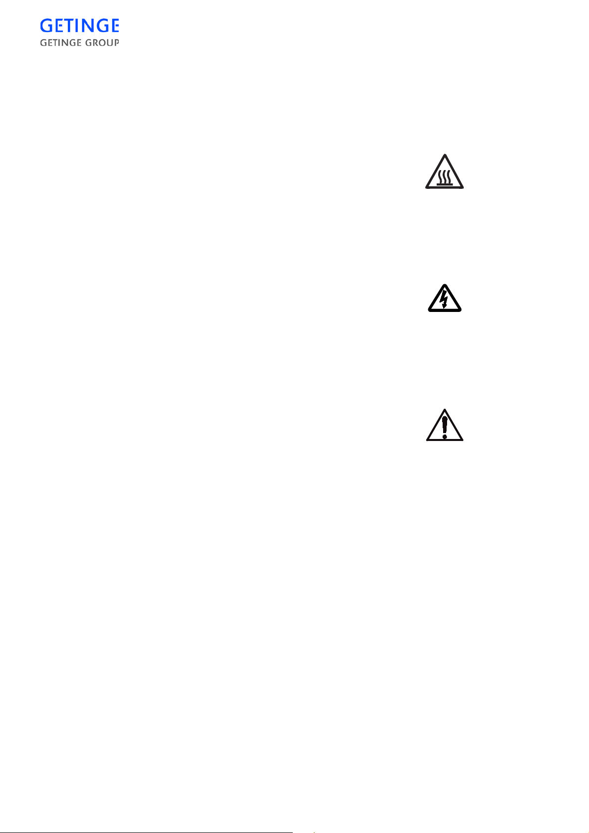
Symbols on the unit
Hot surface
This symbol warns of a hot surface.
Electrical danger
This symbol warns of an electrical danger.
Other dangers
This symbol warns of other dangers.
4 -
SAFETY
Page 9

Reporting an accide nt or incident
Use this information when reporting incidents and accidents involving the unit.
If an accident or an inci dent associated with the ster ilizers occurs, t his
must be reported immediately in writing to the address below. The
report must be used to identify the cause of the accident or incident and
to what extent the occurrence was due to the unit
The unit is a product in the GETINGE range.
The unit may also be a sterilizer that is a medical engineering product
and which conforms to the EU medical devices dire ctive, or which is
constructed in a similar way to a medical device. Under the medical
devices directive, the manufacturer must investigate t he cause of accidents/incidents that occur and report them to the authorities concerned.
The investigation may lead to changes in new or already delivered
devices or in instructions and guidance.
The following circumstances must be reported:
1. Circumstances that caused the death of a patient, user or someone
else, or that caused serious deterioration in the health of a patient,
user or someone else.
2. Circumstances that might have caused, the death of a patient, user
or someone else, or that might have caused serious deterioration in
the health of a patient, user or someone else.
The following infor mation is required :
The manufacturing number of the unit (on a label in the electrical cabinet), Date/time of event, Description of event, Consequences of event.
Contact: Name, Phone number, Address:, E-mail:
The information must be sent by letter or fax to:
GETINGE STERILIZATION AB
For the attention of: Quality Manager
Box 69
305 05 GETINGE
Sweden
Fax: +46 (0)35 549 52
SAFETY -
5
Page 10

6 -
SAFETY
Page 11
MAINTENANCE
To be done by trained technicians only
ESD (Electrostatic discharge)
ESD damage in installation and servicing may destroy the
electronic equipment. Read the instructions in the “ESD”
section in the Installation chapter, in the INSTALLATION
MANUAL, BEFORE starting work.
Overview of safety devices
Cladding and front panels must prevent access to the parts
of the installation that are normally accessible only to
trained personnel.
General access to an installation supplied without cladding must be prevented. Cladding should normally only be
maintained by trained personnel. A convenient way of preventing access is to install the equipment in a lockable
area.
The cladding panels of the unit, or if none are fitted, the room in which
the unit is installed, must ensure that only authorized and specially
trained personnel can have access to the internal parts of the installation.
Safety components
Each unit is fitted with a number of components with the specific purpose of ensuring personal safety. These items are marked with the
warning triangle below in the follow in g documen ts:
•
electrical diagrams
•
pipework diagrams
•
spare parts lists
These components have undergone special tests before being accepted
as safety components. For this reason, they must not be replaced with
components of any make or design that has not been appr oved by
MAINTENANCE -
7
Page 12
GETINGE. It is of the highest importa nce that the operational reliability
of these components is cont inuously upheld during the entire service
life of the installation. The signs are used not only to indicate im portant
components, but also to draw attention to other safety factors that call
for special attention, such as dimensions, tolerances, materials, etc.
Independent process monitoring
As well as being equipped with the PACS 3500 control system, the sterilizer is equipped with the PACS Supervisor monitoring system.
The monitoring system uses a pressure transmitter independent of the
control system to monitor the pressure in the chamber. If the chamber
pressure is too high, the monitoring system prevents the door bein g
opened.
The system is described in general terms under Control unit, and pressure monitoring is described under “Safety blocking of door opening”
under Door.
General requirem ens
When working behind panels, be aware of the risks of
injury by crushing, cutting and burning, and of the risk s of
live electrical equipment.
The need for maintenance depen ds chiefly on the extent to which the
sterilizer is used. The frequency of preventive measures will therefore
vary from case to case. If the sterilizer is used to its full capacity, and/
or the quality of the media is poor, more maintenance may be required.
Note that the end user is responsible for ensuring that pressure vessels
are inspected and safety valves are checked in accordance with the
requirements of the supervisory authority in each country; see also
“Responsibility for pressure vessels and safety valves” at the end of the
Installation chapter in the INSTALLATION MANUAL.
Methods for checking safety valves (where applicable) are described
under “Checking safety valves” under Advice and instructions.
8 -
MAINTENANCE
Instructions for fitting bursting disks (where applicable) are given under
“Installing bursting disks” in the chapter headed Components.
Getinge AB will only accept responsibility for product safe ty and,
where applicable, for CE marking, if the following minimum requirements are met by the user.
Page 13

•
The sterilizer has been installed in accordance with Getinge AB’s
instructions and drawings.
•
Operators and maintenance personnel have been trained for their
tasks. Getinge AB can offer such training.
•
Consumables, spare parts and accessories used must have been
approved by Getinge AB.
•
Equipment must be maintained in accordanc e with the mainte nance
chart in the TECHNICAL MANUAL or more often.
•
Any modifications must be approved and documented by Getinge
AB and be done by authorized personnel.
After commissioning
When the sterilizer has been in service for one month, deposits and particles from new pipes will have collected in filters and sensitive components. If these deposits are not dealt with they will cause malfunctions,
leakage and reduced performance.
•
Clean all dirt filters and restrictors.
•
Clean all steam traps. Remove deposits on their seats and floats.
•
Check that the pipework of the installation and unit is leaktight.
•
Check that all the electrical connection screws on power, earth and
neutral cables are tight.
Clean the plastic strainer in the float valve inlet.
•
Clean the plastic strainer in the cooling water valve inlet.
•
Check the flow rate, and rectify them if they are not correct. See
under "Heat exchangers" in the Components chapter.
•
Perform a leaktightness test by running the Leakage test process. See
“Leakage test” under The process in the USER MANUAL .
After a long idle period
After the sterilizer has been idle for a long time, it is advisable to carry
out the actions below. A long idle period may be a shutdown or a holiday.
During the idle period
•
If possible, the unit should be started and operated once a week.
On starting after the idle period:
•
Run an approved leakage test.
MAINTENANCE -
9
Page 14
Maintenance plan
Replacing the air-in filter
Depending on the size of the sterilizer, the air-in filter must be changed,
after a certain number of processes as stat ed below, or when pressure
equalisation takes too long.
In any event, the filter must be changed at least once a year.
The filter units should be replaced more often if the environment is damp or dusty.
HS 6606: 300 cycles
HS 6610: 275 cycles
HS 6613: 250 cycles
Once a week
Monthly
Quarterly
HS 6617: 200 cycles
HS 6620: 175 cycles
Check that the door closing motion can be stopped by gently push-
•
ing, the squeeze protection plate in the door anti-motion direction.
•
Check the operation of printer pens, ink cartridges and/or ribbons,
for example by checking the graphical printout. Replace if necessary.
•
Carry out the maintenance under “Monthly”.
10 -
MAINTENANCE
•
Check the operation of the pressure reducing valve by reading the
pressure gage marked “Steam supply” during a process. The pressure
must be within the working range of the sterilizer.
•
Check the door seal. Replace the seal if necessary. See the chapter
DOOR. Note that special operating conditions and/or media quality
may require shorter or longer intervals.
Page 15

Each half year
•
Perform a leaktightness test by running the Leakage test process. See
“Leakage test” in the USER MANUAL.
Perform the maintenance operations described under “Monthly” up to
and including “Quarterly”.
•
Clean all dirt filters and restrictors.
•
Clean all steam traps. Remove deposits on their seats and floats.
•
Check that the pipework and hoses of the installation and unit is leaktight. Seal all leaks. Replace any leaking gaskets.
•
Check that all the electrical connection screws on power, earth and
neutral cables are tight.
•
Clean the plastic strainer in the float valve inlet.
•
Clean the plastic strainer in the cooling water valve inlet.
•
Perform the following maintenance operations, which are described
in more detail under Door.
·
Check the door action.
•
Check that the door motor is firmly secured.
•
Check that the V-belt is free from defects. Replace it if necessary.
•
Perform the following maintenance operations, which are described
in more detail under Door.
·
Checking and adjusting the door position vertically, horizontally
and depthwise.
·
Checking the operation of door seal and seal groove valves.
·
Replacement, where necessary, of the door seal.
·
Perform safety checks as described in “Door safety devices”.
·
Perform safety checks as described in “Interlocking the start
function”.
·
Safety checks as described in “Blocking of chamber media
supply.”
·
Safety checks as described in “Safety blocking of door opening.”
•
The feedwater tank for integral or external steam generators for process steam must be regularly cleaned to prevent the growth of algae
and bacteria. Observe local restrictions and the recommendations of
hygienists. Note that bacteria and algae that find their way into the
steam generator may form pyrogens that end up on and in the sterile
goods.
•
The header tank must be regularly cleaned to prevent the growth of
algae and bacteria. Observe local restrictions and the recommendations of hygienists. Note that bacteria and algae that find their way
MAINTENANCE -
11
Page 16

into the steam generator may form pyrogens that end up on and in the
sterile goods.
•
Check that the Pt100 temperature sensor(s) is/are undamaged. The
sensor in the outlet must be adjusted so that the tip is 90 mm below
the bottom surface of the chamber.
If the basic setting was changed at a validation, that setting takes
precedence over the figure stated above.
•
Check the flow rate, and rectify them if they are not correct. See
under "Heat exchangers" in the Components chapter.
•
Clean the holes and nipples described under “Vacuum pump”, “Cavitation protection” in the Components chapter. With the sterilizer in
service, check that air is drawn into the pump.
•
Print out the list of the twenty most recent faults (se e the Control unit
chapter) and assess whether these indicate faults in components or
incorrect settings.
•
Check the operation of the operator panel display, any LEDs and
printer, if any. See the Control unit chapter.
Yearly
•
Perform the maintenance operations described under “Monthly” up
to and including “Six monthly”.
•
Temperature sensors and pressure sensors connected to the control
system must be checked against an independent system with documented accuracy, traceable to a national standard. Note that the
measurement error of the reference instrument must not exceed onethird of the measurement inaccuracy to be achieved. National standards and local regulations must be complied with.
Temperature check: We recommend doing the check in ice water
at 0 °C (32 °F) and in an oil bath at process temperature, eg 121 °C
(250 °F). It is very important to allow the sensors to stabilise in the
baths before doing the check. An ice bath must be filled with crushed
ice and be properly stirred.
The temperature measuring error must not exceed 0.5 °C (0.9 °F).
Calibration of temperature sensors, see Control unit .
Pressure check: A reference instrument for pressure checking is
usually combined with equipment for raising and lowering the pressure. If this is not the case, the check can often be done by connecting
the reference instrument directly to the unit and using the built-in
features to alter the pressure. Note that the pressure measuring system of the unit can detect pressure changes within ± 1 mbar / ±0.1
kPa / ±0.0145 psi and that the permitted measurement error below
refers to absolute levels for the entire range.
12 -
MAINTENANCE
Page 17

The pressure measurement error must not e xceed ±8 m bar / ±0.8 kPa
/ ±0.115 psi within a range 0-1 bar(a) / 0-100 kPa(a) / 0-14.5 psia.
At pressures above 1 bar(a) / 100 kPa(a) / 14.5 psia, the difference
must not be greater than 0.01 x P(a). Calibration of pressure sensors,
see Control unit.
If the pressure sensor of the unit is removed, the gasket
must be replaced with a genuine GETINGE spare part.
•
Check the accuracy of the recorder. A check must always be done
after a malfunction of the recorder.
•
Check and adjust the water level in the feedwater tank so that it is
about 12 mm below the overflow.
•
Check that the feedwater inlet pipe discharges at least 20 mm above
the overflow outlet.
•
Check that the inlet and return water do not cause bubbles in the
feedwater. Bubble formation oxygenates the feedwater, increasing
the amount of non-condensable gases in the steam produced.
•
Check and adjust the amount of sealwater to the vacuum pump and
where applicable its cavitation protection, according to the
instructions under “Vacuum pump” in the Components chapter.
•
Check the pressure on the outlet of the pressure rising pump. It shall
not be below 3,0 bar. If the pressure is to low it can affect the overall
performance of the process.
•
Run all processes while checking pressure, temperature, times and
the operation of the indicator lamps. File the relevant process documentation such as recorders charts, process printouts or log files
from the test runs.
Additional maintenance operations, every second year
•
Perform the following operations, as described in the “Heat exchangers” section of the Components chapter.
·
If the water is harder than 4 dH (70 ppm), clean all plate-type heat
exchangers.
·
Pressure-test all the heat exchangers.
•
Replace the contactors for the pressure rising pump every fourth
year.
MAINTENANCE -
13
Page 18

Warranty
Service
Spare parts
Warranty conditions and warranty period are described in the commercial documentation. See the order confirmation that governs the terms
of delivery for this unit.
Contact your local GETINGE representative.
Contact your local GETINGE representative.
14 -
MAINTENANCE
Page 19
ADVICE AND INSTRUCTIONS
Manual intervention in the process
When faults occur during a process because of interruptions in the supply of media or component faults, the process may, after an alarm has
been triggered, get stuck in a phase from which the control equipment
cannot proceed.
In that case, various options are open to the user. The options that do not
involve a hazard to the operator are described in the “Alarms” section
in chapter Operation in the USER MANUAL. If the operator’s options
for action are not possible or do not solve the problem, a trained technician must be called to advance the program manually.
With the stepping option a technician can, under certain
circumstances, manually bypass built-in sa fety conditions.
Manual stepping with the ke y switch
For manual stepping in a program, activate: Stepping/
Authorized user and press
Then select
program.
During Stepping/Authorized user all parameters are regulated by the
automatic control equipment through which normally no hazardous situations can occur. Manual control involves stepping from one process
phase to another without meeting the temperature, time, or pressure
conditions.
For safety reasons, the ability to step past critical process conditions is
blocked. This applies to certain pressure, temperature and level conditions, except when there is a fault in an analog sensor. Stepping of the
program should take place while the unit is still in the alarm phase.
Step
and press
More
Enter
repeatedly to step in the
ADVICE AND INSTRUCTIONS -
15
Page 20
In this event, no blocks exist to prevent hazardous situations from arising. It is completely up to the technician to
decide which operations are permitted.
The method described above may only be used by technicians who are thoroughly familiar with the process, the
properties of the goods and the functioning of the individual components.
Manual intervention in the process
When faults occur during a process because of interruptions in the supply of media or component faults, the process may, after an alarm has
been triggered, get stuck in a phase from which the control equipment
cannot proceed.
Various options are then open to the user. Options that do not invo lve a
hazard to the operator are described in the “Alarms” section i n chapter
Operation in the USER MANUAL. If the operator’s options for action
are not possible or do not solve the problem, a trained technician must
be called to advance the program manually.
With the stepping option, a technician can under certain
circumstances manually bypass built-in sa fety c onditions.
Manual stepping with the key switch
For manual stepping in a program, activate: Stepping/
Authorized user and press
Then press
During Stepping/Authorized user all par amaters are re gulated by the
automatic control equipment through which normally no hazardous situations can occur. With manual control, the program is stepped from
one process phase to another wit hout meeting temperature, time, or
pressure conditions.
Step
repeatedly to step in the program.
More
16 -
ADVICE AND INSTRUCTIONS
Page 21
For safety reasons, the ability to step past critical process conditions is
blocked. This applies, among other things, to certain pressure, temperature, and level conditions, except when there is a fault in an analog
sensor.. Stepping of the program should take place while the unit is still
in the alarm phase.
In this event, the blocks that prevent hazardous situations
from arising do not exist. In this case, it is completely up to
the technician to decide which operations are permitted.
The method described above may only be used by technicians who are thoroughly familiar with the process, the
properties of the goods and the functioning of the individual components.
Faulty analog sensor
If an analog pressure sensor or temperature sensor becomes faulty during a process, the process stops. The type of fault does not allow restarting of the process, since the sensor fault persists after
acknowledgement, even if it is not indicated again. Another consequence of a faulty analog sensor is that no pressure or temperature controller becomes operative. This in turn means that neither temperature,
pressure nor ramped temperature changes can be controlled.
With a pressure sensor fault, the operator must also step past the pressure conditions on post-vacuum, evacuation, emptying, self-cooling
and pressure equalisation. With a temperature sensor fault, the operator
must step past the corresponding temperature conditions.
Sensor fault, independent system
In case the process is stopped in a cooling- or door opening phase, due
to failure of the independent sensors, the safety system can be by-passed
by manual operation of the safety relays.
See the electric wiring diagram.
ADVICE AND INSTRUCTIONS -
17
Page 22

Pressure sensor fault
Processes with drying vacuum, shutting down a program:
In principle there are two ways of getting out of the process in the event
of a pressure sensor fault, A) automatic shutdown or B) manual
shutdown. Both methods require calling a technician who can activate
Stepping/Au thoriz ed user to be able to reach standby mode. To avoid
unintended stepping or holding of the process, reset th e system b etween
each stepping operation.
A) Automatic shutdown:
•
The process jumps automatically to posttreatment if the sterilizer is configured for
automatic shutdown on alarm. See
chapter Control unit. If this is not the
case, the process jumps on to posttreatment by selecting
Enter
.
Start
and pressing
Note! The process will be controlled with
rapid evacuation. The ramp regulator
does not start.
•
When the vacuum pump has run for 30
minutes, the program moves on to
pressure equalization. At the same time,
the “wait for atmospheric pressure”
message appears on the display.
•
Wait until atmospheric pressure is
established in the chamber.
•
Activate Stepping/Authorized user and
press
More
.
•
Then step out of the pressure equalization
phase by selecting
Enter
.
B) Manual shutdown:
Note! The option of manual shutdown is only offered when the steriliz er is not
configured for automatic shutdown on alarm, see chapter Control unit .
Step
and pressing
18 -
ADVICE AND INSTRUCTIONS
Page 23
•
Equalize the pressure in the chamber to
atmospheric pressure by manually
opening the valve for the drain or the
pressure equalizing filter or support
pressure. See chapter Control unit.
Check the pressure using the chamber’s
pressure gauge.
•
Activate Stepping/Authorized user and
press
More
.
•
Then step out of the process by selecting
Step
and pressing
Note! A start attempt when Stepping/Authorized user is activated, the process
restarts where it stopped. This causes a new alarm and secondary faults
when the pressure sensor is faulty.
Enter
repeatedly.
Processes with drying vacuum, shutting down a program:
In principle there are two ways of getting out of the process in the event
of a pressure sensor fault, A) automatic or B) manual shutdown. Both
methods require calling a technician who can activate Stepping/
Authorized us er to be able to reach standby mode. To avoid unintended
stepping or holding of the process, reset the system between each
stepping operation.
A) Automatic shutdown:
•
The process jumps automatically to post-treatment if
the sterilizer is configured for automatic shutdown on
alarm. See chapter Control unit. If this is not the case,
the process jumps on to post-treatment by selecting
Start
.
Note! The process will be controlled with rapid
evacuation. The ramp regulator does not start.
•
When the vacuum pump has run for 30 minutes, the
program moves on to pressure equalization. At the
same time, the “wait for atmospheric pressure”
message appears on the display.
•
Wait until atmospheric pressure is established in the
chamber.
ADVICE AND INSTRUCTIONS -
19
Page 24

•
Activate Stepping/Authorized user and then step out
of the pressure equalization phase by pressing the
More
button and then
B) Manual shutdown:
Note! The option of manual shutdown is only offered when the steriliz er is not
configured for automatic shutdown on alarm, see chapter Control unit.
•
Equalize the pressure in the chamber to atmospheric
pressure by manually opening the valve for the drain
or the pressure equalizing filter or support pressure.
See chapter Control unit. Check the pressure on the
chamber pressure gauge.
•
Aktivate Stepping/Authorized user and press
•
Then step out of the process by pressing
repeatedly.
Step
.
More
.
Enter
Note! A start attempt when Stepping/Au thorized user is activated, the process
restarts where it stopped. This causes a new alarm and secondary faults
when the pressure sensor is faulty.
Temperature sensor fault
Process with drying vacuum, shutting down a program:
In principle there are two different ways of getting out of the process in
the event of a temperatur e sensor fault, A) automatic shutdown or B)
manual shutdown. Method B) re quires calling a technician who ca n
activate Stepping/Authorized user to be able to reach standby mode.
A) Automatic shutdown:
•
The process automatically goes to posttreatment when the sterilizer is
configured for automatic shutdown on
alarm. See chapter Control unit.
Otherwise the process goes on to post-
Start
treatment by selecting
Enter
.
and pressing
20 -
ADVICE AND INSTRUCTIONS
Page 25

•
Post-vacuum and pressure equalization
are normally carried out. Then the
process is shut down.
B) Manual shutdown:
Note! The possibility of manual shutdown is only given when the sterilizer is
not configured for automatic shutdown with alarm.
•
Activate the key switch to the Stepping/
Authorized user setting and press
•
Then step the process to the posttreatment phase by selecting
press
Enter
repeatedly.
•
Start post-treatment by selecting
press
Enter
. Post-vacuum and pressure
Step
More
and
Start
.
and
equalisation are normally carried out.
Then the process is shut down.
Note! A new start attempt when Stepping/Authorized user is activated the
process restarts where it stopped. This sets off a new alarm and secondary faults when the pressure sensor is faulty.
Process with dry vacuum, shutdown of the program.
There are two principally different ways of going outside of the process
in case of a temperature sensor fault, A) automatic shutdown or B)
manual shutdown. Method B) requires calling a technician who
activates St epping/Authorized user to be able to reach the sta ndby
phase.
A) Automatic shutdown:
•
The process automatically goes to post-treatment
when the sterilizer is configured for automatic
shutdown on alarm. See chapter Control unit.
Otherwise, the process goes on to post-treatment by
pressing
•
Post-vacuum and pressure equalization are normally
carried out. Then the process is shut down.
Start
.
B) Manual shutdown:
Note! The possibility of manual shutdown is only given when the sterilizer is
not configured for automatic shutdown with alarm.
ADVICE AND INSTRUCTIONS -
21
Page 26

•
Activate the key switch to the Stepping/Authorized
user setting and press
•
Then step the process to the post-treatment phase by
pressing
•
Start post-treatment by pressing
and pressure equalization are normally carried out.
Then the process is shutdown.
Note! A new start attempt when Stepping/Autho rized user is activa ted the
process restarts where it stopped. This sets off a new alarm and secondary faults when the pressure sensor is faulty.
Step
repeatedly.
More
.
Start
. Post-vacuum
Manual control by manually actuating the control
valves
The above method can be used to check the operation of individual
components, for troubleshoot ing and with system faults that keep the
process in the same phase.
When operating from menus on the operator panel or via a program
tool, there are no software interlocks to prevent hazardous situations
arising. See chapter Control unit for precise information about which
menus are used at each interface.
When control valves are operated directly there are no interlocks at all.
We advise against this form of control.
Note that when operating via the operator panel or programming tool, it
is extremely important that all outputs are reset to auto mode when the
work is complete. If this is not done, the safety and operation of the unit
will be at risk during the remainder of the process.
Normally the operator is informed at the start of the next process if an
output is set to manual mode. Despite this, the status must always be
reset to auto mode immediately on completion of work.
When using this method, the blocks that prevent hazardous situations from arising are removed. The technician
himself has to decide which operations are permitted.
22 -
ADVICE AND INSTRUCTIONS
Page 27

External safety interlock fault
The sterilizer is equipped with an automatic monitoring system for
those external components that serve as safety interlocks independently
of the control system.
If the external components changed their position, or got stuck and are
constantly indicating “safe position”, this would not normally have
been noticed in service. It would only have been discovered when it was
too late and the control system ha also failed, ie when the external components were needed for safety purposes.
The purpose of the monitoring system is to ensure the operation of both
the safety systems that allow media, among other things, to be admitted
to the chamber or the door to be opened.
Monitoring is done by a system of relays which is in contact with the
external components and the control system. At certain predetermined
places before and during the process, the control system checks by
means of the relay monitoring that the respective external component
has opened or closed its contacts as expected.
If the relay information does not agree with the control system’s own
information, the control system stores the discrepanc y until the proce ss
has ended.
After the process, an alarm i s activated and a message indicate d what
type of interlocking is present (see also “Fault codes” in chapter Oper-
ation in the USER MANUAL).
The alarm cannot be reset in the normal way, and as long as the alarm
is activated, a new process cannot be started.
INTERLOCK FAULTS
•
Silence the alarm signal by pressing
Enter
.
•
Rectify the faulty component if
possible.
•
Activate Stepping/Authorized user.
•
Finish the current cycle.
•
Reset the alarm by pressing
then select
•
Set the component and do a safety
check. The procedure is described in
the Door chapter.
Ack.
and press
More
Enter
and
.
•
Silence the alarm signal by pressing the
alarm signal
button.
Silence
ADVICE AND INSTRUCTIONS -
23
Page 28
•
Rectify the faulty component if possible.
•
Activate Stepping/Authorized User.
•
Finish the current cycle.
•
Reset the alarm by pressing
•
Set the component and do a safety check. The
procedure is described in the Door chapter.
Backup battery fault
If there is a fault in the control system backup battery, an alarm is triggered when the current process has ended and the control system ha s
returned to the standby phase. In this mode, no parameters or program
sequences have been lost. Data is only lost if the power to the control
system is turned off with the main switch or if there is a power failure.
More
and then
Ack.
Before shutting down:
1. Save the program in the flash memory or in a file; see also chapterControl unit.
2. Make sure that the program has been saved, so that it can be
reloaded.
3. Only turn off the operating current when you quite certain that the
program has been saved.
Replace battery
The battery cannot be replaced. Instead, order an replacement CPU
board if a new battery is needed.
WARNING!
Lithium battery. Explosion hazard.
We advise against any attempt to replace the battery!
If a new battery is needed, order a replacement card.
Never replace the battery with a type other than that supplied.
24 -
ADVICE AND INSTRUCTIONS
When operating voltage is lost:
If the backup battery voltage is low at the same time as a power failure
occurs during a process, all software is lost.
Page 29
The control system can no longer check the process, and the unit must
be brought to a safe mode by manual control. See the description of the
menus for testing digital outputs in chapter Control unit.
When using this method, the blocks that prevent hazardous situations from arising are removed. The technician
himself has to decide which operations are permitted.
The above method may only be used by technicians who
are thoroughly familiar with the process, the properties of
the load and the functioning of the individual components.
Note: If the control unit PROM is to be used to restore the
software by a “cold start”, when the unit has been brought
to a safe mode, all changes made and calibrations done
since delivery are deleted.
Restoring software from E_PROM (cold start)
Cold start may only be done with the unit in a safe mode
and by a technician who is thoroughly familiar with the
process.
Read the warning below and then the cold-starting instructions in chapter Control unit.
Warning
When programs are loaded from a PC or on cold starting from a PROM,
the system goes to standby phase; this means that risky situations may
occur.
Before loading/cold start, the unit must first be brought to the standby
phase or brought manually to a non-hazardous phase where the vessel
contains no water and/or condensate, is depressurised and any liquid
loads have coole d. See also the separate instructions fo r manual handling in this chapter.
A cold start from the PROM means that old values will appear for settings that have been changed in the RAM.
In a similar way saved, old values are loaded from PC. This makes it
ADVICE AND INSTRUCTIONS -
25
Page 30
necessary to update any changes and calibration values. Calibration values from the latest calibration for analog sensors must also be entered.
Manual door opening
The following important steps must be taken into consideration before a door is opened after manual intervention.
•
Identify the valve that is to be operat ed, to be sure that it really is the
proper valve.
•
Manually open a drain valve, to drain the chamber of liquids.
•
Depressurise the chamber by opening the drain valve.
•
If the load consists of liquid, the door must not be opened until the
temperature of the liquid is well below its boiling point.
Power failure alarm with door open
If a sterilizer door is partly or wholly open, an alarm will be generated
for safety reasons after a power failure. The doors must therefore always
be closed when the control power supply is turned off.
Functions that can be programmed by the us er
Barring codes
In the control system there are different code levels, permitting different
types of action. The purpose of these codes is to prevent people who do
not have the necessary knowledge or authority intentionally or
accidentally accessing operations whose consequences they cannot
foresee.
The following important steps must be taken before the
door may be opened manually.
26 -
ADVICE AND INSTRUCTIONS
Note that ethylene oxide is an odorless, colorless and very
toxic gas. Make sure that evacuation of the chamber will
take place via the catalyzer or in a safe place outside the
building.
Page 31

It is important that the codes only be shared with the people who will
need them
for their work and who have the required qualifications/authority.
1. Operator code
This code bars the starting of programs that are designed as test
programs, emergency programs or for the sterilization of liquids.
Common for these programs
is that they need not be validated for routine sterilization.
On some sterilizers, the authorization code (password) al so prevents the
door being opened after a failed cycle.
2. Supervisor code
This code prevents unintentional changes being made in the control
system calendar.
The supervisor is also authorized to create new codes (passwo rds) on
operator and parameter level and to print out the program
documentation.
3. Service code
This code prevents access to menus for settings and tests that may only
be done by an authorized technician.
4. Programming code
This code blocks access to the menus where the sequence program can
be edited.
This code is only used by users in exceptional cases, since this
authorization requires very detailed knowledge of the program-ming of
the control system, as well as the design and operation of the sterilizer.
Changing the program description parameters
The parameters that are most likely to need changing during programming at the user’s premises are listed in the programming combination.
The ability to change parameters in a program combination varies from
one apparatus to another. Some equipment has a very large number of
selectable parameters; other equipment has few or none. The degree of
possible adapta tion depends on the user ’s requirements and of ficial
demands within the application, and on the level of training of the operators.
As well as parameters for sterilizing temperature and time it is sometimes possible to adapt the post-treatment of the processes to achieve
maximum dryness of goods that are difficult to dry, to set the desired
liquid temperature, or to protec t the gods from over-rapid change s of
pressure and temperature.
See also the section on setting the parameter values in chapter Control
unit. Suitable settings for steam sterilizers with different types of goods
ADVICE AND INSTRUCTIONS -
27
Page 32
Validation
are described i n the separate GETINGE guide STERILIZATION
WITH STEAM.
The manufacturer has type-tested the sterilizer with the reference loads
prescribed in European standards. In some cases, supplementary type or
performance tests to other standards are performed, where national
standards require this.
The reference loads used are regarded as requiring the sterilizer performance needed to ensure sterilization of various types of load in daily
use in health care.
However, in order to ensure the correct performance, a user-related
European standard requires the sterilizer to be validated with type-loads
that are equivalent to those that will subsequently be sterilized in the
sterilizer.
Normally the sterilizer passes this validatio n without the need for
adjustments. If it does not pass, this may be because the user’s typeloads require a different performance from that specified in the product
standards or because the performance of the sterilizer has deteriorated.
Modification of program parameters at validation
The sterilizer is capable of being reconfigured to handle such a situation
and can be modified on site, within certain limits. Generally, reconfiguration requires a change to the pre-treatment stage of the sterilisation
process. To carry out such a reconfiguration calls for considerable
insight into and knowledge of the importance of pre-treatment for the
sterilization result, as well as training in programming.
NOTE: To ensure effective sterilization, always contact
Getinge AB when adjusting the pre-treatment.
Modification of door function
On completion of a sterilization process, the discharge door of sterilizers with two doors is opened automatically. After processes intended
solely for testing or maintenance, the loading door is normally only
opened when the door knob is pressed in.
By modifying a parameter value it is possible to modify the door function individually for each program. It is necessary to have access to the
programming code to be able to make this modification.
28 -
ADVICE AND INSTRUCTIONS
Parameter values
0 = The discharge door opens automatically following an approved
process.
Page 33

1 = The discharge door only opens when the door knob is pressed in.
2 = The discharge door does not open. The loading door opens when the
door pushbutton is pressed.
NOTE: Only personnel who have been trained to program
PACS may perform the following change. In the menus
concerned, incorrect programming may result in changes
to the basic program that mean immediate danger.
Programming from CS1000:
1. Go to the “System” menu.
2. Choose the “Phases & Programs” menu.
3. Enter the password and exit the menu with “OK”.
4. Open the “Programs” file tree and choose the program to be
changed by clicking “+”.
Date and time
Calibration
5. Select the “PROCESS COMPLETE” phase and right-click.
6. Choose “Edit parameter list” in the menu.
7. Double-click the “Door function” parameter under set value.
8. Change the parameter value to the required value.
9. Click “OK” to confirm and exit the menu.
10. Select the required program in the file tree and right-click.
11. Choose “Save in PACS” in the list.
12. The change is complete. Quit “Phases & Programs” by pressing
“X” on the button, on the second line top right.
The service code gives access to menus where the date and time can be
changed. See chapter Control unit.
Analog sensors/transducers must be calibrated, for example when
replaced. The calibration menu can be accessed by using the service
code. See the section on menus for calibration in chapter Control unit.
When using an oil bath, note the following points:
A Accuracy must meet current standards, eg EN285.
ADVICE AND INSTRUCTIONS -
29
Page 34
B Contaminants in the oil may cause coatings and therefore have a
drastic effect on the accuracy of measurement. Change the oil at
regular intervals!
C Use an oil bath with a large capacity, preferably more than five
litres.
D Allow measuring instruments and the oil bath to stabilize for an
hour or two after the bath reaches the set temperature.
E Allow the oil bath to stabilize for at least 30 minutes after the sen-
sors are placed in the bath and the bath has returned to the set temperature.
F Clean the sensors thoroughly to remove the oil after calibration.
NOTE: If the PROM of the control unit will be used to
restore the software by means of a “cold s tart”, calibration
done after delivery will be deleted and replaced with the
original calibration.
Setting the sterilizer number
The PACS address is an identification of a given apparatus that is used
during communication between the operator panels or Getinge AB’s
computer programs. The number, which must be chosen from the range
1 - 99, also serves as an identification on printed detailed graphs of cycle
data, thus making the graphs traceable.
The programming proceeds as follows:
•
Go to the menu Settings - Communication.
•
Enter the sterilizer number in accordance with the instructions for
this menu as given in chapter Control Unit.
•
Exit the menu.
Log interval for cycle data
The logging interval can be changed so that more or less measurement
data is printed out. Logging during the sterile phase is controlled by the
value “Short interval”, whilst printout of data during the other parts of
the cycle is controlled by the value “Long interval”. The factory setting
of both these values is 59 min 59 sec. which usually only gives printout
of data when a subprocess is changed.
See also the “Printer” section in chapter Operation in the USER
MANUAL, or if the equipment includes Supervisor, the section entitled
“Documentation of the cycle” in chapter The Process in the USER
MANUAL.
30 -
ADVICE AND INSTRUCTIONS
The programming proceeds as follows:
Page 35
•
Go to the menu Settings - Printer Setup.
•
Set the desired short and fast logging interval in accordance with the
instructions for the menu in chapter Control unit.
•
Exit the menu.
Adaptation of the sterilizer to high water temperature and lo w water
pressure.
If necessary, the sterilizer can be provided with “tropical setting” by
changing the settings of the dip-switches in the system menu. Doing this
adapts the system to handle water temperatures up to 35 oC and water
pressures down to 1 bar(g) [14.5 psig].
This adaptation is achieved by reinforcing the cooling and at the same
time restricting the first part of the post-treatment. This limits the temperature of the waste water to about 90°C during the first four minutes,
after which it falls.
NOTE: The sterilizer must be re-validated a fter this change.
ADVICE AND INSTRUCTIONS -
31
Page 36

32 -
ADVICE AND INSTRUCTIONS
Page 37
THE DOOR
General
The opening and closing motion of the door is executed by a pneumatic
cylinder. The door motion speed is controlled by adjustable chokes in
the cylinder admittance pipe. As a safety measure there is a squeeze protection integrated in the top of the door.
When the door is completely closed, it is locked mechanically. This
lock activates a limi t switch which makes it possible to pressurize the
door seal.
During a process and in the event of media failure (electric power,
steam or compressed air) the doors are kept locked by the automatic
control equipment and the door lock described above. The doors cannot
be opened until the condition ''chamber pressure = zero (±100 mbar)'' is
met, not even if an electrical fault results in an opening command.
The door closing system is made up of a number of components. Their interaction has been carefully tes ted to give
the necessary safety in terms of damage to equipment and
injury to people. These parts must not be subjected to violence or incorrect operat ion that may alter their original
function.
Adjustments to doors and associated equipment may only
be made by authorized personnel.
Seal between door an d ch am be r
The seal between the door and ch amber is formed by a rubber ga sket
which can move in a groove around the opening of the chamber.
The moving door seal is pressed against the door by steam, compressed
air or an inert gas. The media used depends on the type of unit. The door
seal is released when the pressure medium is evacuated.
Some special types of sterilizer are fitted with double door seals. Where
two door seals are used on a negative pressure sterilizer, only the outer
seal can move.
THE DOOR -
33
Page 38
Media to the chamber
Before media can be admitted to the chamber, all the requirements
below must be met:
A Emergency stop not activated
B Door(s) closed.
C Door seal pressurized.
D Control system giving a control signal to open the media valves.
Checking the door action
The speed of motion of the door can be changed with the variable
restrictor in the air line to the door cylinder. Changing the closing speed
has an equal effect on the opening speed.
1. Check that the door closes in 10-15 seconds. Adjust the restrictor if
necessary (see pipework diagram).
2. Check that the motion is even and smooth.
3. Check that the door does not scrape against anything during its
motion. Adjustment advice is given under “Adjusting the door position”.
Checking and adjusting the door position
Always disconnect the compressed air supply before
removing to door or adjusting its position. This ensures
that the door does not move accidentally.
A. VERTICALLY
This adjustment may be necessary of the 3 mm dimension between the
top edge of the door and the bottom of the chamber is not maintained,
or if the door does not fully cover the seal groove.
34 -
1. Measure the door adjustment required.
2. Open the front.
3. Raise the door by activating its pilot valve by hand.
THE DOOR
Page 39
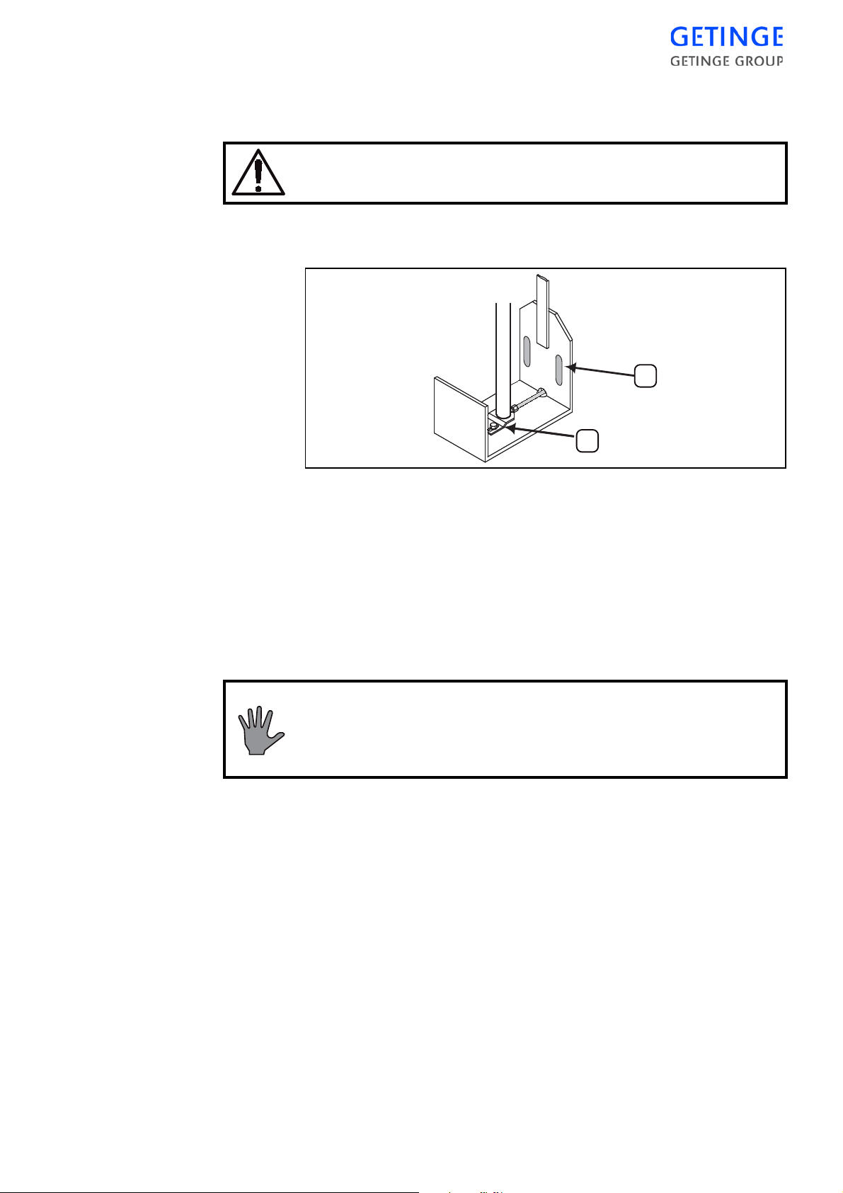
4. Insert a prop under the door and lower the door until it rests on the
A
B
prop.
Make sure the door is resting securely on the prop.
5. Loosen the support bracket (A) and adjust the door to the measurement, then tighten the screws.
6. Pressurize the door cylinder, remove the prop and lower the door.
Check its vertical position and re-adjust if necessary.
B. SIDEWAYS
7. Check that the closed door completely covers the seal groove (the
tolerances on the cylinder stroke are close).
8. Check that the top edge of the door is horizontal. If necessary,
slacken the piston rod guide plate (B) for adjustment and move the
piston rod sideways. Tighten the fixing plate screws.
9. Refit removed parts.
The setting of the door locking mechanism must be
checked after adjustment. See under “Interlocking of the
start function”.
This adjustment may be needed if the lateral clearance of 2-3 mm
between the door and the guides is not maintained.
1. Open the front.
2. Slightly slacken the side guide attachment nuts F.
3. Adjust the lateral position of the door with the screws E to give a
lateral clearance of 2 - 3 mm relative to the guides.
4. The door must cover the chamber symmetrically, with the minor
deviations that may be required for the clearance to the cladding
plates.
THE DOOR -
35
Page 40
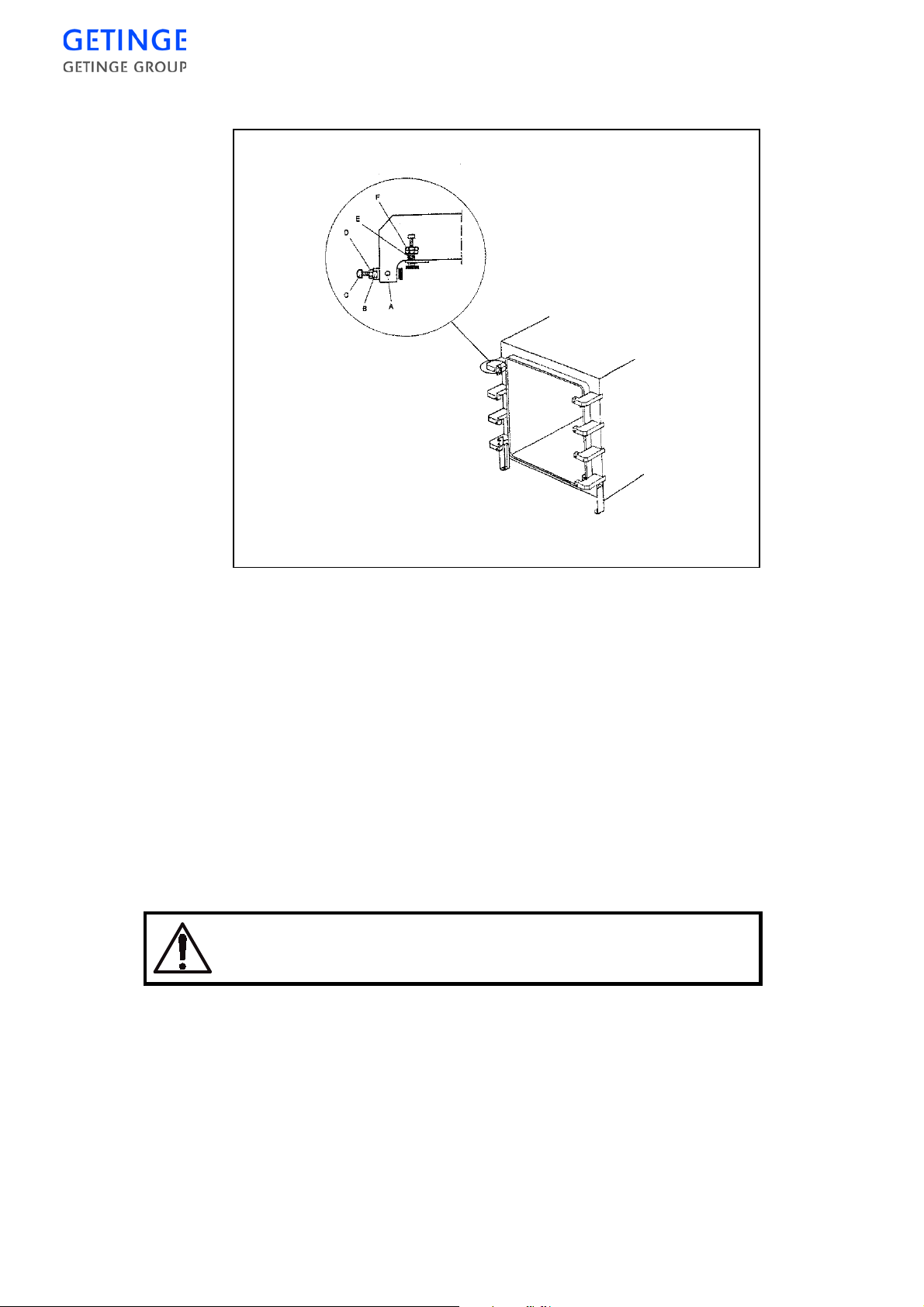
5. When adjustment is complete, secure the side guides with the nuts
F.
C. IN DEPTH
This adjustment may be necessary if the distance between the door and
the chamber is not correct.
1. The clearance between the door surface and the door seal groove
should be about 2.5 mm.
2. Open the front.
3. Slightly slacken locking screws A and locking nut D.
4. Close the door and insert at each corner a strip of sheet steel 2.5 mm
thick between the door and the seal groove (slacken B if necessary).
5. Adjust B until the metal strips are gripped very lightly.
Important: tighten screws and nuts firmly. These screws
and nuts are an integral part of the pressure vessel.
6. Tighten D and A.
36 -
THE DOOR
Page 41
Door seal
7. Remove the metal strips.
The setting of the door locking mechanism must be
checked after adjustment. See under “Interlocking of the
start function”.
The door seal is the part of the pressure vessel that is most exposed to
wear and tear. Material composition, design, installatio n and care are
extremely important for safe operation and long life of the seal.
GETINGE's door seal is made of a s pecially-formulated silicone
material and its shape is designed to enhance its particular properties.
Use only a GETINGE door seal. Remember that the seal is
an integral part of the pressure vessel.
Care
There are several negative factors that are of critical significance to the
useful life of the door seal. By avoiding these as much as possible, the
useful life of the seal can be prolonged considerably.
•
Avoid leaving the sterilizer in standby mode over night. Despite the
door seal tolerating over 200°C continuously, its contact surface with
the seal groove is slowly broken down. The life of a sterilizer that is
always on standby is shortened by approx. 60%.
•
Empty any steam generators at the prescribed intervals. In all
feedwater, except deionized water, a large concentration of minerals
and other substances builds up. At high concentrations, many of
these substances follow the steam and are deposited on the seal as
weak acids.
•
If the sterilizer is connected to the central steam, the steam quality is
of critical significance. Often, chemicals are added to the feedwater
to protect pipes, for instance. Undesireable chemical properties of
steam include a high content of Hydrazine or Carbon Dioxide.
•
Keep the seal groove clean.
THE DOOR -
37
Page 42
Checking the performance of the door seal and packing groove
valves
Perform a leak test, as described in the Process chapter in the USER
MANUAL. If the test runs witho ut disturbances, above valves are
working properly.
•
In case the steam valve, for the groove, doesn't open the leak test will
stop.
•
If the steam valve for the sealing groove does not close, or if the drain
valve does not open, the door cannot be opened after the test as a
result of friction against the door seal. The same thing will occur if
the seal has hardened or if the absence of its lubricant layer has
caused it to fasten in the sealing groove.
WARNING - Risk of crushing
Be very careful if the door remains fastened to the seal.
When it comes away from the seal, it will drop down out of
control.
Preparations
•
If the leak test results in a pressure rise, this can be due to a number
of effects, one of which is a leaking steam valve to the chamber or a
worn seal. A leak of this type will also make it difficult to maintain
a constant temperature in the chamber.
•
If a similar pressure rise occurs particularly during the sterilization
phase of programs with high sterilization temperatures, it indicates
that the door seal is worn out.
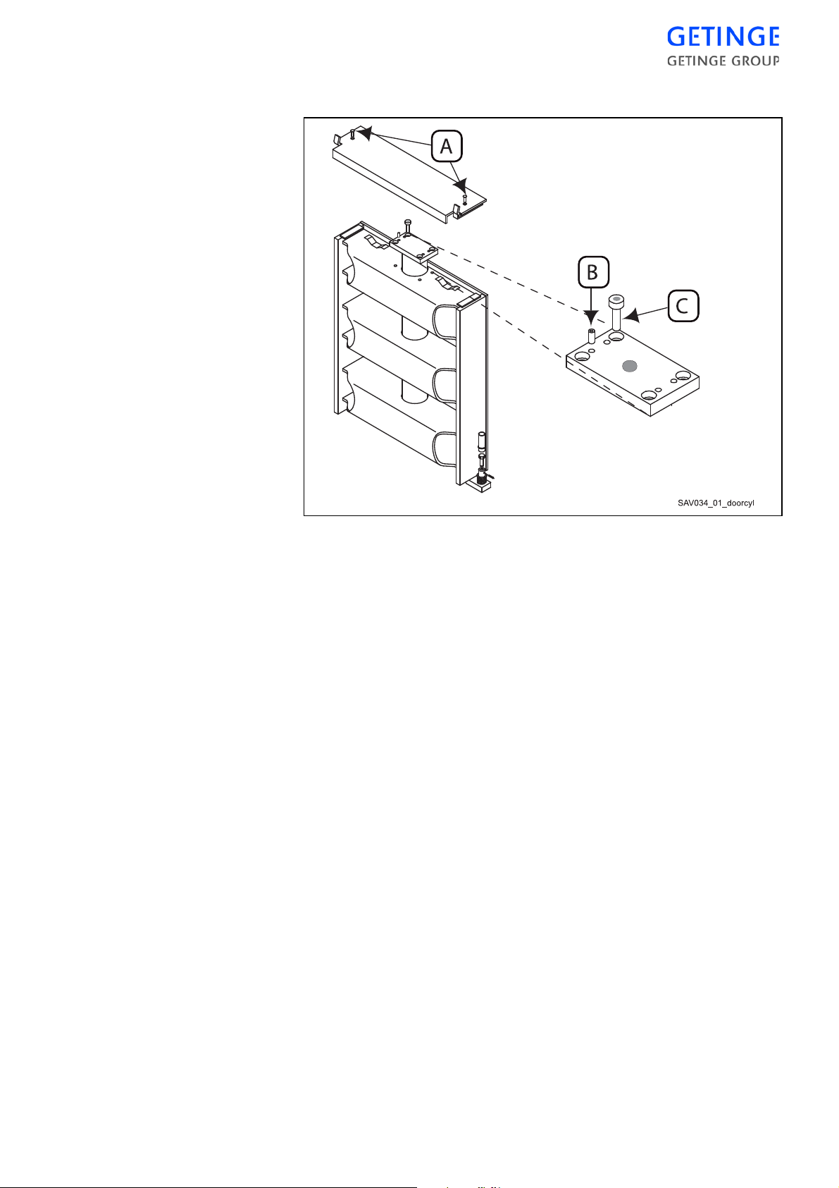
1. Remove one of the safety plate screws (“A” in the illustration on
page 41) and slide the plate towards the empty screw hole until the
opposite end comes off. Lift it off carefully.
The door is pushed forward by the spring when the safety
plate is removed. Take care to avoid being trapped.
38 -
Make sure that it is impossible to close the door while work
is in progress by turning off the control power and
disconnecting the compressed air supply.
If, when the door is in its forward position, it is allowed to move
upwards, the gap between the sealing groove and the door will
THE DOOR
Page 43

immediately decrease from about 16 mm to 2.5 mm. There is nothing to
reduce the force be hind this movement, and it could severely c rush a
hand etc.
Removal and cleaning
1. Remove the seal from the groove. Be careful with the seal and the
groove.
2. Carefully clean the seal groove.
·
First remove any coatings of hardened lubricant with a very fine
emery cloth (no coarser than 320 grit)
·
Then wash the groove with a soap solution and wipe dry with
clean paper.
·
Wash again until the paper is clean after wiping.
On fitting
1. Check that the spring is in place at the bottom of the groove.
New seal
2. When fitting a new seal, it is extremely important that the excess
length is distributed correctly. It helps to have the assistance of a
second person.
3. Press the seal join into the middle of the upper horizontal part of the
groove.
4. Secure the seal in the middle of the straight parts of the groove so
that its excess length is equally distributed between the fixing
points.
5. Press in the seal between the previous fixing points, dividing the
sections into smaller and smaller parts so that the entire excess
length is equally distributed over the entire length.
6. Work some of the surplus towards the corners so that the seal can
properly fill the full radius width of the groove.
7. Finally press the entire seal into pla ce so that it is inside the edge of
the groove.
8. Fit the safety plate by moving towards the side in which there is no
screw, pressing it down and engaging it on the side in which the
screw has been left. Tighten the securing screw and check its performance.
THE DOOR -
39
Page 44
Changing the door cylinder
1. Close the door by operating its air solenoid valve by hand.
2. Place a block or similar to stop the door about 150 mm from the bottom position when it is lowered by manual activation of the cylinder
solenoid valve in the next operation.
The door must be securely supported.
3. Remove the hose connection at the foot of the piston, lift the door
slightly, remove the block and lower the door completely.
4. Remove one of the safety plate attachment screws “A” and push the
plate towards the empty screw hole until it comes free at the opposite end. The door is now pushed forward by the spring.
Beware of the risk of crushing when the block and/or safety
plate is removed.
5. Using a 6 mm Allen key, remove the four cylinder attachment
screws “C”.
6. Prevent the piston rod from moving out of the cylinder by keeping
the safety valve at the bottom of the cylinder in the raised (closed)
position. Lift out the door cylinder.
7. Attach nipple and hose to the piston rod of the replacement cylinder.
8. Position the cylinder in the door. Prevent the piston rod from moving out of the cylinder, as described above, or tie it back with wire.
9. Attach the cylinder with the four All en screws. With the four adjusting screws “B”, centre the cylinder on the notches of the stiffening
bars.
40 -
THE DOOR
Page 45
10. Attach the guide washer in the position that makes the piston and
piston rod move correctly.
Replacing the piston seal
A faulty piston seal can not be replaced. The ent ire piston must be
replaced with a new complete unit.
Remove the door cylinder as described in steps 1 - 7 of the previous section.
1. Fix the door cylinder in a vise, using moderate force.
2. Remove the attachment plate from the end plate.
3. Twist the cylinder end plate until the end of the locking wire
appears in the locking wire hole in the cylinder pipe.
4. Twist the cylinder end plate in the direction that feeds the locking
wire through the hole. Use a suitable tool to help the wire enter the
hole.
5. Pull out the bent end of the locking wire from the driver hole.
6. Remove the cylinder end plate. Replace its O-ring even if it appears
to be free from damage.
7. Push out the piston and fix it in a vise.
8. Protect the piston rod tube from tool marks with a strip of soft sheet
metal around its lower end, where it is stiffened internally by a brass
insert. At that point (and nowhere else on the piston rod) apply a
polygrip wrench or similar tool.
THE DOOR -
41
Page 46
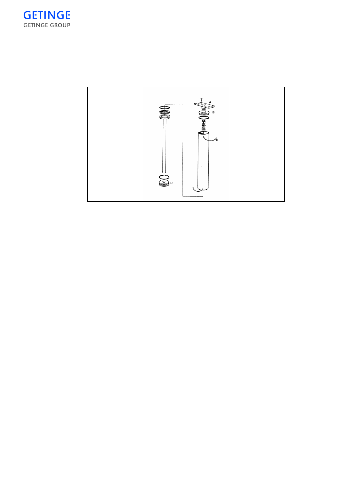
9. Unscrew the piston rod from the piston. If necessary, apply a small
amount of heat to soften the thread sealing compound. Clean the
piston rod thread with a steel wire brush.
10. Apply “Loctite 542 hydraulic sealing compound” to the thread and
screw the new piston on to the piston rod.
11. Refit the door cylinder.
Door safety devices
Crush protection
The door is actuated by a pneumatic cylinder. The entire surface of the
top edge of the door is covered by a sheet steel plate of stable form,
which is attached so that it deflects when pressure is applied from
above, wherever the pressure is applie d. The motion of th e plate acts
directly, without intervening components, on a genero usly-dimensioned valve at the end plate of the c ylinder. This rapidly releases the
working air, stopping the motion of the door. For this to work as
intended, the amount of air released must at all times be greater than the
amount or air supplied. This is guaranteed by a built-in fixed restrictor
in the air supply line, which cannot be adjusted from outside.
Safety check
1. Check that the air supply pressure is the maximum permissible, 8
bar.
2. Fully open the door speed control valve.
42 -
THE DOOR
Page 47
Emergency stop
3. Manually close the solenoid valve for the door operating air to
make the door close.
The safety check must be performed as soon as the door
starts to move, in order to minimise any risk of crushing.
4. Press the centre of the door's safety strip and check that it is free to
move so that the cylinder exhaust valve opens without substantial
downward pressure. Check at other positions along the safety strip,
that the required downward pressure is not excessive anywhere.
5. If the strip is held down, the exhaust blowoff must be so powerful
that the door reverses direction and is lowered.
When the emergency stop button is pressed, the motion of the door is
blocked the and control system goes to alarm mode.
Safety check
1. Open the door. Press the emergency stop button while door is moving. The door must stop and the control system must give an alarm.
Reset the alarm and the emergency stop button, and give another
door opening command.
2. Close the door and repeat the function check during the closing
motion.
If the above functions do not work, immediately cal l a qualified sterilizer engineer to carry out checks and adjustments.
Interlocking of the start function
The closing motion of the vertically sliding automatic sterilizer door
provided by a single-acting pneumatic cylinder. To ensure that the door
does not open under its own weight is air pressure is lost for a long time,
the door is held up by a support, which is moved to its latching position
under the door cylinder. This hap pens 20 seconds after the issue of a
door closing command. A limit switch senses the position of the support
and prevents the process being started and media being admitted to the
chamber before the door is completely closed.
THE DOOR -
43
Page 48
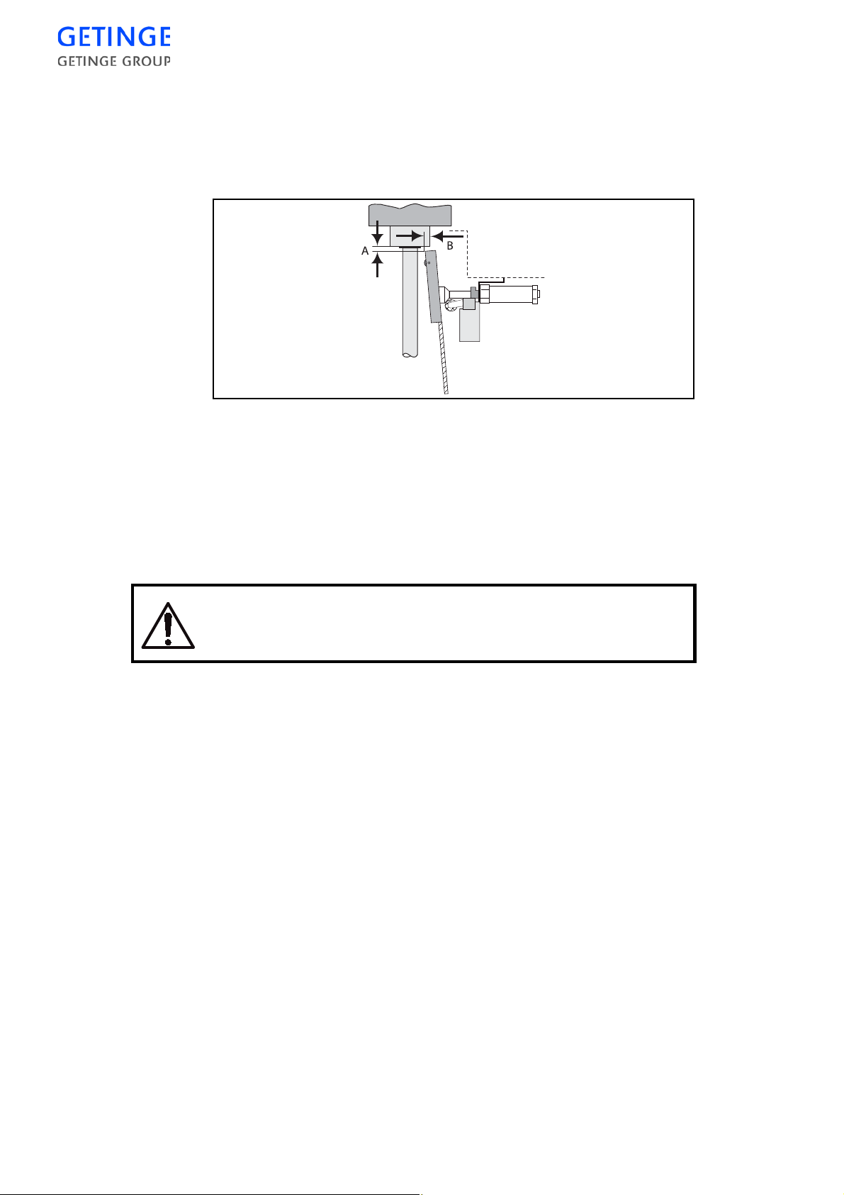
Safety check
1. Make sure that the minimum permitted air pressure, 6 bar, is
present.
2. Open the solenoid valve for the door cylinder operating air so that
the door closes.
3. Check that the measurement “A” is 3-4 mm. Adjust the height of
the support if necessary.
4. Check that the end of the support is well within the cylinder circumference. (“B” ≥ 11 mm)
5. While moving the support to and fro by hand, listen to check that
the limit switch contacts do not change over until the roller is safely
under the door cylinder.
When working with the door latch, be aware of the risk of
crush injury.
6. Check that the retaining pin which prevents the piston rod cam from
moving on the thread is in place.
7. Check by repeated operation of the latch cylinder solenoid valve
that the motion of the piston is distinct, with no tendency to bind.
8. Cylinder retraction is restricted in order to reduce the noise level.
The spring return, however, is not restricted. Adjust the retraction
rate if necessary.
9. Check the screws securing the support and their condition.
Blocking the media supply to the chamber
Media supply to the chamber requires several safety systems to be
intact. The systems are all independent of the control system and cut off
the electric power supply to the media valves.
44 -
THE DOOR
Page 49

Limit switches
Emergency stop
A limit switch senses that the door is fully closed before the signal is
passed to the media valve.
Adjustment
For safety reasons, the limit switch cannot be adjusted.
Safety check
1. Switch on the operating current with the doors closed and check
that there is voltage at the GASKET terminal.
2. Open the door on one side and check that the voltage disappears
from the GASKET terminal.
3. On double-ended sterilizers, do the same check on the door switch
on the other side as well, possibly after a process with opening
restrictions on the door.
An emergency stop button breaks the circuit when pressed.
Safety check
1. Start a process and check that there is voltage at the MEDIA termi-
nal. Note: This check must not be done until after the seal has
sealed.
2. Press the emergency stop button on the one side and check that
there is no voltage at the MEDIA terminal. Reset the emergency
stop button and check that there is voltage again at the MEDIAter-
minal.
3. Finish the process.
4. On a double-ended sterilizer, do the same check with the emergency stop button on the other side as well.
Pressure switch, door seal pressure
A pressure switch with two electrical contacts as the activating devices
senses the pressure in the door seal groove and closes the valves which
admit steam, compressed air, gas etc. to the chamber in case the seal
groove pressure should fall below prescribed value. With double ended
sterilizers there is normally one pressure switch for both doors because
these have a common pressure supply.
This is not the case with double-ended sterilizers with an SPF function,
for which each door has its own pressure switch.
The pressure switch(es) interrupt(s) the electrical supply to the valves
by means of auxili ary relay 1. The second co ntact (auxiliary relay 2)
interrupts a signal to an input of the control system, generating an alarm.
See the electrical circuit diagram in order to identify the components
concerned.
THE DOOR -
45
Page 50

Adjustment
1. Switch off the control unit power switch when the sterilizer is in
standby mode.
2. Close the incoming steam and air supplies.
3. Remove the capillary tube and connect a reference instrument to the
seal pressure switch. Initially the pressure switch must be kept at
atmospheric pressure.
4. Remove the cover of the pressure switch.
5. Turn the pressure setting nuts clockwise until contact changeover is
heard.
6. Set the reference instrument to 1.6 bar(e).
7. Switch on the power at the main switch.
8. Slowly turn the adjusting nut for pressure switch contact group 2
anticlockwise until the LED on the control unit input goes out.
9. Set the reference instrument to 1.9 bar(e).
10. Slowly turn the adjusting nut of the pressure switch contact with
connector interface 1 anticlockwise until contact changeover is
heard. If necessary use a circuit tester, lamp or similar to detect
when the contact opens.
11. Continue the safety check as below from step 5).
Safety check
1. Switch off the control unit power switch when the sterilizer is in
standby mode.
2. Close the incoming steam and air supplies.
3. Remove the capillary tube and connect a reference instrument to the
seal pressure switch.
4. Switch on the power at the main switch.
5. Increase the pressure until the reference instrument reads 2 bar(e).
6. Slowly reduce the pressure with the reference instrument until contact interface 2 changes over and the LED on the control unit input
goes out. The pressure must be between 1.60 and 1.70 bar(e) when
the contact operates.
7. Close sterilizer doors(s), check that emergency stops have been
reset and connect a test lamp or similar to terminal MEDIA.
8. Increase the pressure until the reference instrument reads 2.2 bar(e).
Check that the test lamp is lit.
46 -
9. Slowly reduce the pressure with the reference instrument until contact interface 1 changes over and the test lamp goes out. The pressure must be between 1.80 and 1.90 bar(e) when the contact
operates.
10. Remove the test lamp and the reference instrument.
THE DOOR
Page 51

11. Reconnect the capillary tube to the pressure switch and refit the
pressure switch cover.
12. Open the incoming steam and air supplies.
Safety interlocking of the door opening
The safety interlocks to prevent the door opening are duplicated, split
between the control system and an independent supervisory system.
The safety criteria of both systems must be fulfilled before the door can
be opened.
Supervisor, chamber pressure
Adjustment
The interlocking of the Supervisor cannot be adjusted since the pressure
limits for door opening release at programmed into the software. The
pressure is measured with a dedi cate d pressure transmitte r. However, a
defective or incorrectly calibrat ed pressure transmitte r may threaten th e
safety of the interlocking.
Safety check
1. Start a process.
2. Check that terminal OPEN goes dead when the chamber pressure is
(Note: There may be a few secon ds’ delay between the readings on
PACS Supervisor and the PACS 3500 control system.
Calibrate the supervisory system sensors when necessary.
The control system
Adjustment
The safety interlocking provided by the control system is not adjustable,
since the pressure limits for allowing the door to open are programmed
in the software. Pressure is measured with a dedicated pressure sensor
and temperature with dedicated temperature sensors. A faulty or incorrectly calibrated temperature sensor can threaten the safety interlocking.
above 1.2 bar (a) . Read all the values on the control system display
panel, not on the supervisory system control panel. If the values are
taken from PACS Supervisor, you will not be able to determine
whether the system needs to be calibrated.
Safety check
Check the pressure and temperature se nsors with a reference instrument. If an incorrect indication is found, replace faulty sensors and calibrate.
THE DOOR -
47
Page 52

48 -
THE DOOR
Page 53

CONTROL UNIT PACS 3500
The letters PACS stand for Programmable Autoclave Control System.
The purpose of the control system is to issue orders and send them to
the executive components of the unit so that a number of process steps
are performed in accordance wi th a pre det ermined t empl ate. The order
signals are worked out by the computer program of the control unit in
conjunction with measurements of actual parameter values for the cur rent program. These are usually times, temperatures and pressures.
Several different pieces of equipment can be connecte d to the control
unit for programming, monitoring and documenting the processes.
The operator communicates with the control unit via a control panel or
an ordinary PC. There are several versions of the operator-machine
interface, from the simplest, which consists of two pushbuttons and
eight LEDs to show that certain statuses have been reached, to the most
advanced, which allows complete programming of the control system,
among other things.
All operator panels are manufactured to monitor the processes by
displaying all the set parameter values as well as actual values on
request. All relevant data associated with a given process, such as cycle
number, operator number, date, etc., can be entered by the operator.
Programs, system definitions and process data can be documented by
connecting a printer to the unit. A host computer can also be connected
directly to the CPU of the control system.
If necessary, a measurement and monitoring system which is completely independent of the control system, can be set up by providing the
equipment with a SUPERVISOR. This contains a separate CPU and its
own measurement and control boards. The SUPERVISOR performs its
measurements by means of separate temperature and pressure sensors
alongside those of the control unit. The system has links to the control
unit CPU and can therefore use the shared operator panel, as well as
adding the co ntrol unit readin gs to the process documentation. The
SUPERVISOR can also be involved in independent interlocking of
door opening, for example.
The computer contains programs for automatic calibration of the temperature and pressure sensors. Where alternative correction constants
are known, they can be entered manually. The testing functions include
means of activating analog and digital outputs and for monitoring analog and digital inputs.
The control unit hardware is divided, so that the operator panels can
form small separate units that are easy to position at the most suitable
location. CPU, measurement and control boards and the power supply
are installed in separate electrical enclosures which are connected to the
operator panels by shielded cables.
CONTROL UNIT -
49
Page 54

A number of special terms
STERILIZATION refers to the entire series of treatments that make up
a process aimed at achieving the total killing of all living organisms.
This applies to sterilizers and usually includes air removal, heat treatment and a drying phase.
STERILIZING refers to the actual killing part of the process, the heat
treatment.
On the same basis as the two terms above, STERILIZA TION TIME
refers to the duration of the entire process from the start until the obje cts
can be taken out of the sterilizer. The PROCESS TIME is the same as
the sterilization time.
The STERILIZING TIME is only that part of the process for which the
programmed STERILIZING TEMPERATURE exists in the chamber.
In this context, PARAMETERS means FACTORS THAT INFLUENCE THE sterili zatio n pro cess . Exam ples of p aram eters in the s ter ilization process are temperature, pressure, time, humidity, gas
concentration, etc.
PARAMETER VALUES may be permanen tly set in the program, be
adjusted by the operator, be included in selectable recipes or downloaded from a higher-level system.
50 -
CONTROL UNIT
Page 55
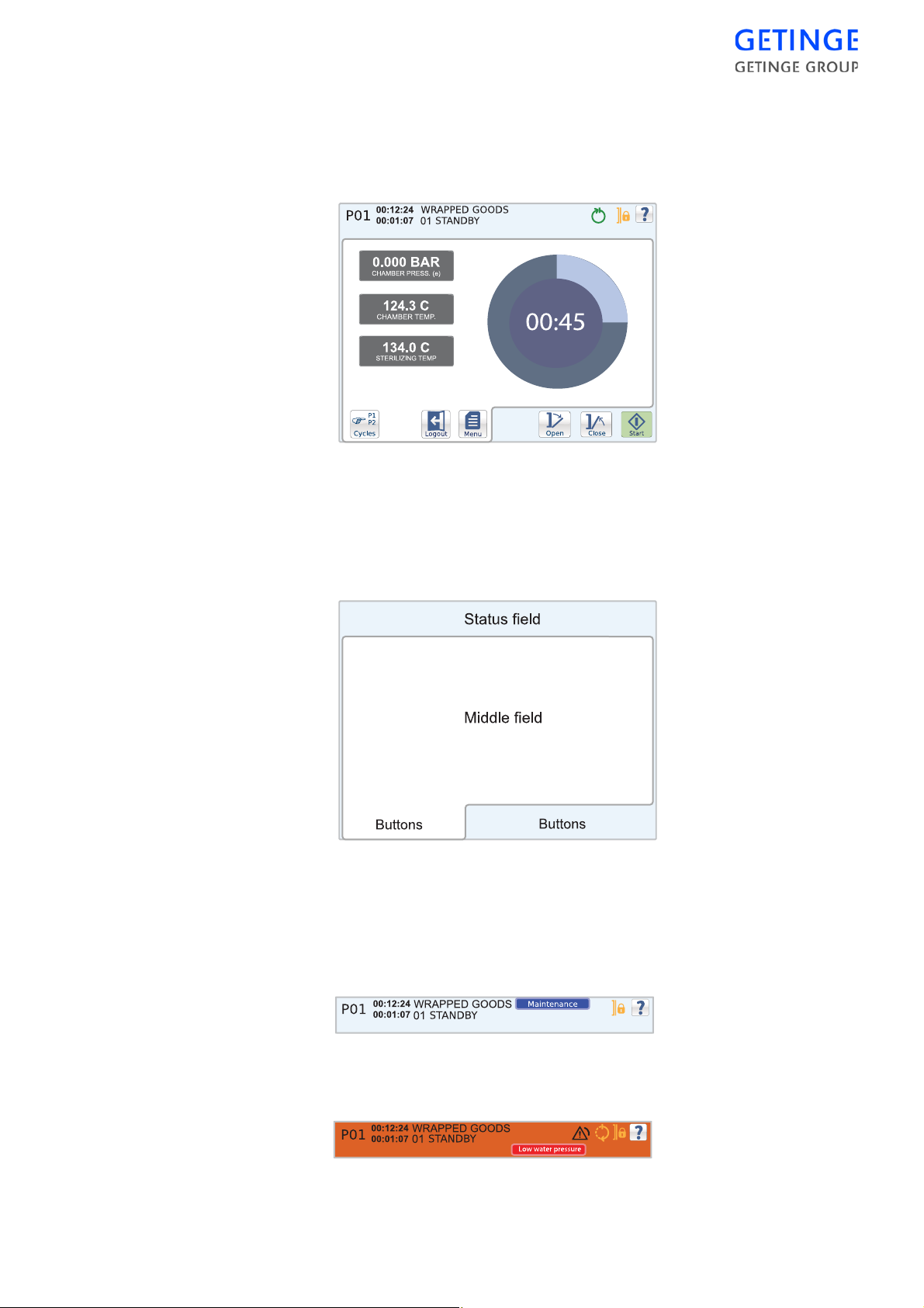
Control panel type Avanti
General description
Screen
The screen can be divided into three areas: status field, middle field and
button field.
Status field
The status field is displayed in all cycle images. The field contains
information about the machine's current status, such as the current cycle
and phase and the time these have lasted. The message is displayed in a
blue box to the left of the indicators.
In the event of an alarm, the status field color changes to red and an error
message displays in a red message box to the left of the indicators.
CONTROL UNIT -
51
Page 56

Middle field
The middle field is specific for the screen and displays unique functions
and information for the respective menus; see the section Screens in the
Main Menu chapter.
Button field
The button field shows the application buttons that are used to give
commands.
52 -
CONTROL UNIT
Page 57
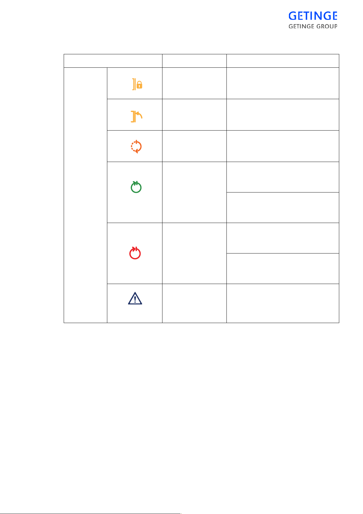
Buttons and symbols
Symbol Operation Description
Indicators Doors locked The machine’s doors are closed
and locked.
Doors closed The doors of the machine are
closed.
Cycle in progress The machine is processing the
selected cycle.
Completed cycle Steady light: Normal cycle
concluded without warnings or
errors.
Flashing light: Test cycle
concluded without warnings or
errors.
Completed cycle Steady light: Cycle concluded, but
a warning and/or error has arisen
during processing.
Flashing light: Test cycle
concluded, but a warning and/or
error has arisen during processing.
Alarm Solid light until the process reaches
"Stand by". Only then can the
alarm be acknowledged by
pressing a button.
CONTROL UNIT -
53
Page 58
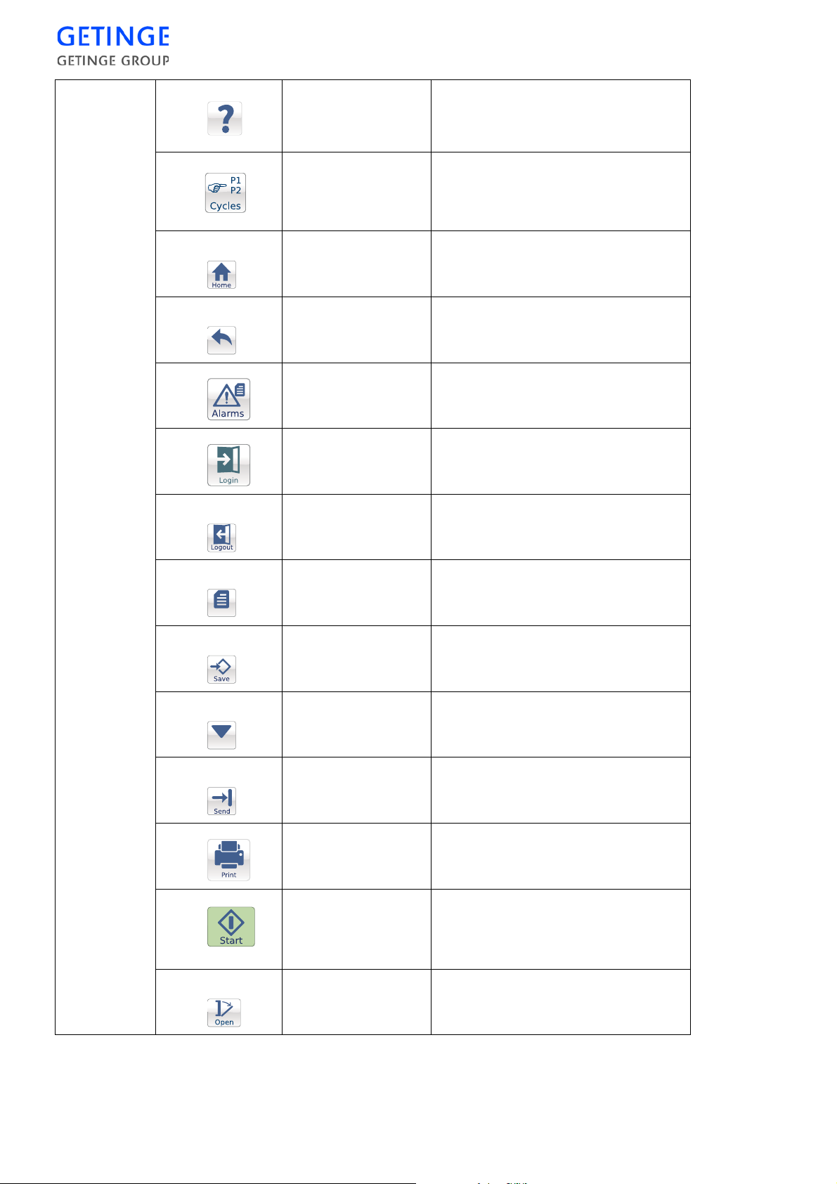
Buttons
Help
No function. For information, see
"User Manual" or "Service
manual."
Back
Cycles
Home
Back
Alarm
Login
Logout
Open menu to select cycle.
Note: Not displayed on the
unloading side.
Display latest start screen.
Return to the previous window or
menu, or undo the input.
Display menu for alarm history.
Display login screen.
Log out current user.
Menu
Calibrate
Menu
Save
Calibrate
Submit
Print
Start
Return to the main menu.
Save edited data.
Execute calibration.
Submit values to the PACS.
Send selected data to the printer.
Start the selected cycle.
Note: Not displayed on the
unloading side.
54 -
CONTROL UNIT
Open
Open machine door.
Page 59
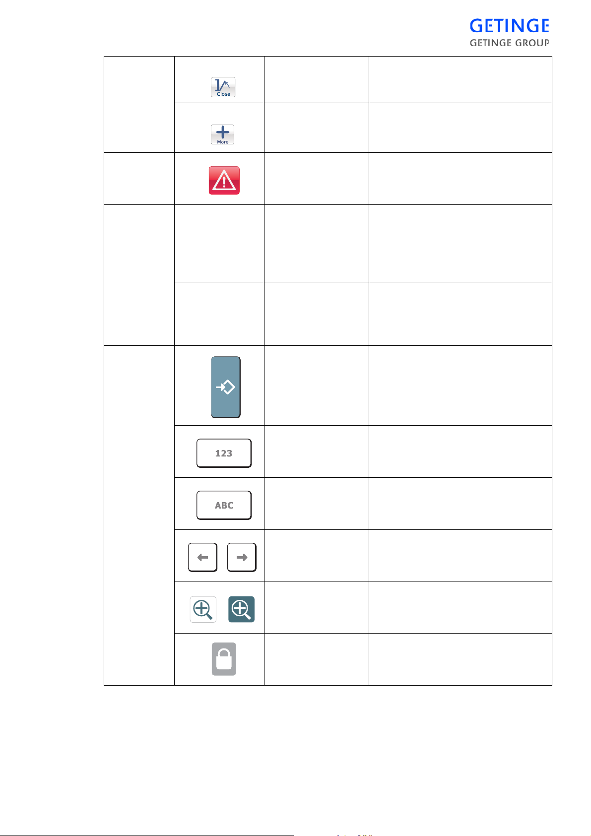
Close
Close machine door.
Alarmhandling
Information
Other
points
More
Optional when alarms or
preprogrammed functions are
active.
Silence alarm
signal
Cycle
information
Switch alarm signal off.
Provides information about
current process and phase, as well
as the time these have been going
on for. The information is
displayed on the top left.
Messages Displayed if an incident occurs.
The message is displayed in a blue
text box on the left of the
indicators.
Save
Save changes and inputted values.
Numeric keyboard
Alphabetic
keyboard
Right
and
left
arrow
Zoom in/out
Insufficient user
access
Shift from alphabetic to numeric
keyboard.
Shift from alphabetic to numeric
keyboard.
Move the cursor in the input
window.
Enlarge/reduce plot graph.
No authorization for accessing the
menu.
CONTROL UNIT -
55
Page 60
Scroll list If there are more rows than space
The various states of the buttons
Active The button can be pressed
Pressed The button is pressed.
Not available If the symbol remains, the button is currently not
available.
available on the scree n, a scroll list
is displayed on the right. To reach
the row above or below, just drag
the button.
Boot screen
Ready to start The cycle can be started.
When the panel starts, the screen below displays. The blue bar moves
from left to right. When the panel is ready and the control system is
ready, the panel automatically switches to the pie chart screen.
56 -
CONTROL UNIT
In case of communication errors between the panel and the operating
system, the blue bar travels back and forth. There is no communication
with the operating system as long as this screen displays and no
command can be sent to the operating system.
Call a service technician.
Page 61
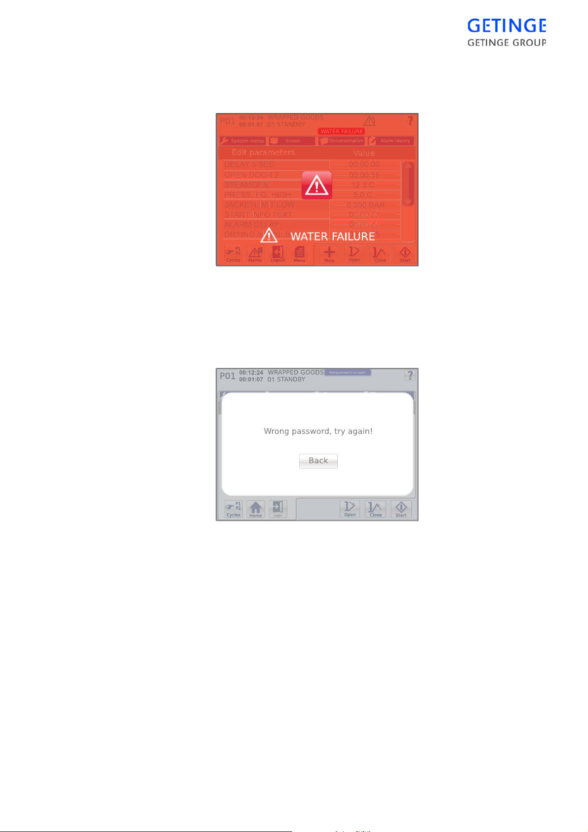
Pop-up windows and dialogue windows
Alarm pop-ups
Shown below is an example of an alarm pop-up.
In the event of an alarm, the current alarm displays as a pop-up window
on the screen and an alarm sounds. For alarm management, see the
"Alarm" section in the chapter Operation of the USER MANUAL.
Information pop-ups
Displayed below is an example of an information pop-up.
The information is displayed on th e screen. P ress the button to return to
the previous procedure screen.
Dialogue window
Shown below is an example of a dialogue pop-up.
CONTROL UNIT -
57
Page 62
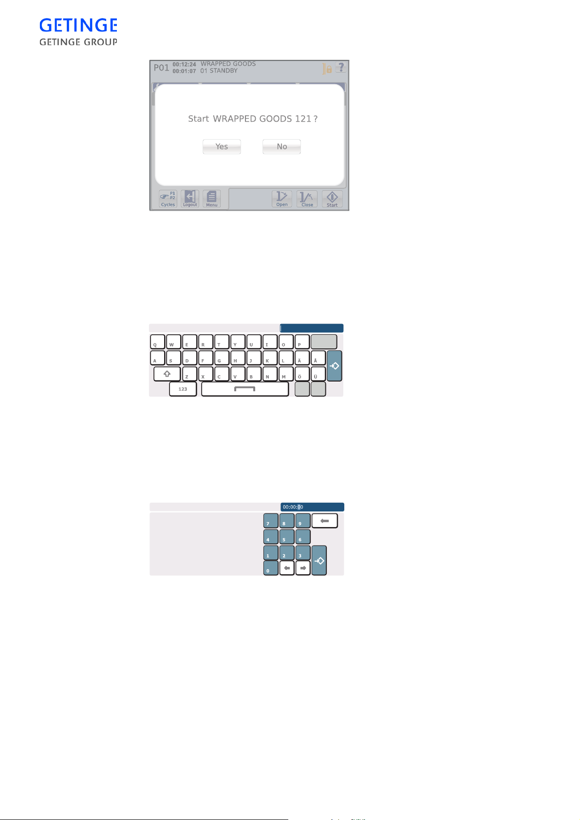
Inputting window
.
The window remains on the screen until a selection is made by pressing
the desired button.
Here are two examples of inputting windows.
To enter a name, press the desired letters.
To toggle between small and capital letters, click the arrow up button
down to the left.
To switch to a numeric keyboard, press the button with numbers at the
bottom left.
Press
Save
furthest to the right to save the entry.
58 -
CONTROL UNIT
To edit the time, mark the number you wish to edit using the arrow keys
at the bottom. Press the desired number. To save the entry, press
Save
at the bottom right.
Different inputting windows exist depending on the input data required.
Page 63
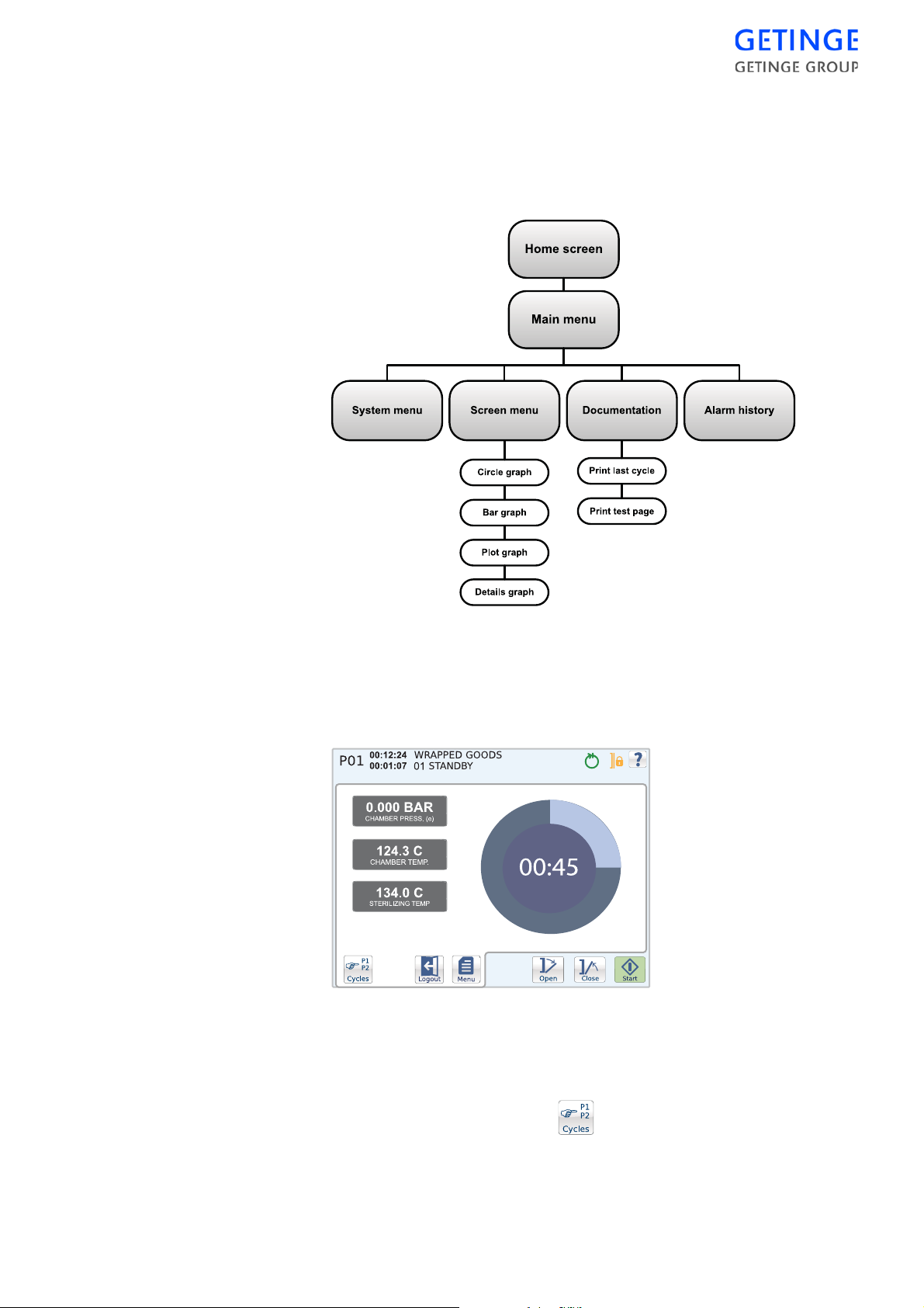
Operator menu Avanti
Description of menus and functions
Start screen
The start screen allows access to the main functions for starting a cycle.
Open/Close door.
The door is opened and closed wi th the
Open
and
Close
buttons,
respectively.
Cycle selection
Cycles are selected with the button in the bottom left corner of
the button field.
A list of optional cycles is shown.
CONTROL UNIT -
59
Page 64
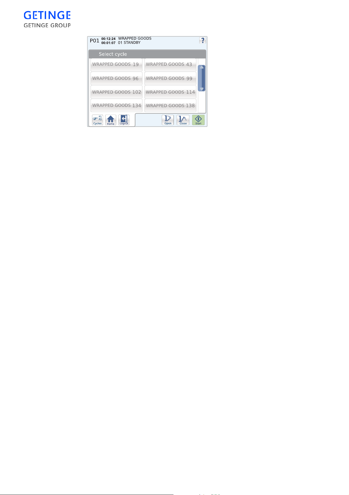
To select a cycle, press the desired cycle. The previous screen is
displayed again.
The selected cycle is displayed in the top left corner of the status field.
Note! The function is not available from the unloading side.
Start cycle
Selected cycles are started with the
Start
button. If the sterilizer is not
ready to start, a message is shown.
Note! The function is not available from the unloading side.
Various information about the current cycle is displayed depending on
the current start screen. For further information, see the Screens section
in Main menu.
The length of time that the cycle or current phase has been running is
displayed in the status field. Also displayed here is the current cycle
indicator.
Login/logout
•
To log in, mark
Login
. An inputting window is displayed for
inputting the password.
Main menu
60 -
CONTROL UNIT
•
Because a user is already logged in, the
Logout
button is displayed
instead. This logs out the current user.
•
Typing in an incorrect password brings up an information window.
Press the
•
If an incorrect password is entered on login when starting the cycle,
Back
button to return to the data entry window.
the panel returns to the previous menu after one minute.
The
Menu
button returns you to the main menu.
System menu
About
A list of machine specific data is displayed.
Page 65
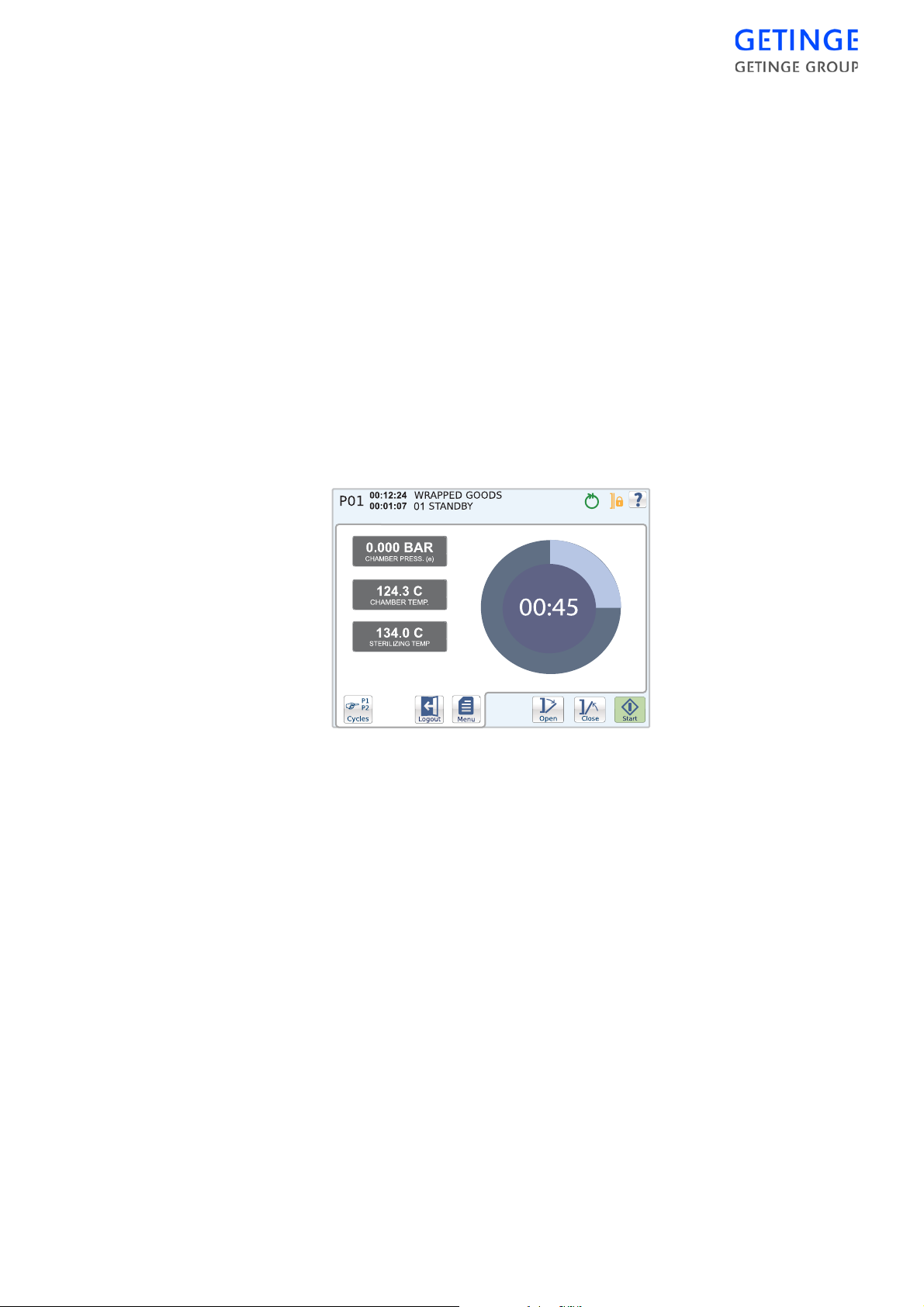
The following information is displayed:
•
Machine name
•
Application version
•
Panel version
•
PACS version
•
PROM date
•
Serial number
•
Total amount of cycles
Other menus require a password and are described in the Service
Manual.
Screens
Circle graph
The start screen shows a pie chart and three cycle parameters.
The pie chart graphically displays the time remaining for the cycle. The
circle diagram also displays the time remaining in digit form.
The following cycle parameters are displayed:
•
Current chamber pressure
•
Current chamber temperature
•
Sterilization temperature for the selected cycle
Bar graph
The start screen displays two cycle param eters, as well as a bar graph
for the respective parameters and cycle time remaining.
CONTROL UNIT -
61
Page 66
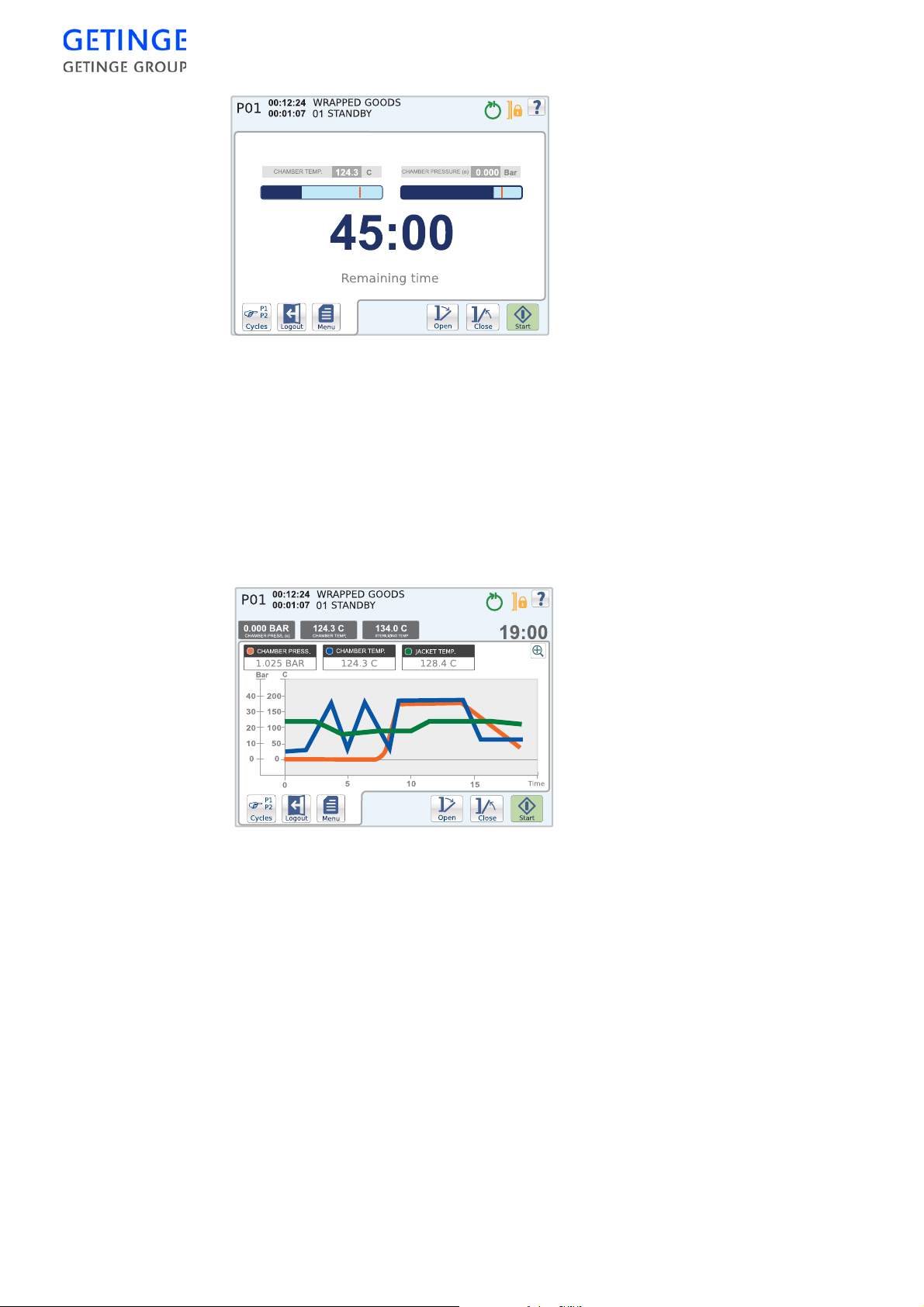
The following cycle parameters are displayed:
•
Current chamber temperature
•
Current chamber pressure
Plot graph
The start screen displays a plot graph with various cycle parameters.
The status field also shows other cycle parameters. The remaining cycle
time is displayed to the right in the status field.
62 -
CONTROL UNIT
The following cycle parameters are displayed in the status field:
•
Current chamber pressure
•
Current chamber temperature
•
Sterilization temperature for the selected cycle
The following cycle parameters are displayed as graphs:
•
Current chamber pressure
•
Current chamber temperature
•
Current jacket temperature
Page 67
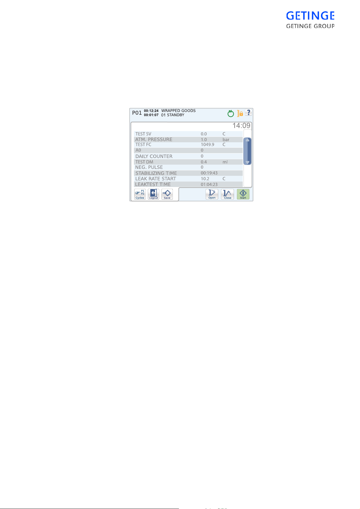
In order to enlarge the graph, press
Zoom in
. When the graph is enlarged
it is possible to navigate by pressing somewhere on the screen and then
dragging with a finger.
Details Graph
The start screen displays a list of parameters that shows information
about the system and the current cycle. The remaining cycle time is
displayed on the top right-hand side, above the list.
Documentation
An pull-down menu w ith optional printout mo des is displayed. The
possibility of choosing printouts varies depending on the user.
The following printout modes exist:
•
Print last cycle, latest cycle run.
•
Print alarm list, list of the most recent alarms. Password required.
•
Print cycle
A list of optional print cycles is displayed. To print, select the print
cycle of your choice and press
•
Print test page
•
Print all cycles. Password required.
•
Print machine setup. Password required.
Printout
. Password required.
Note! It is not possible to print during the current cycle.
Alarm history
A list of the last 20 alarms is displayed.
For more detailed information about an alarm, press the alarm you wish
to select.
CONTROL UNIT -
63
Page 68
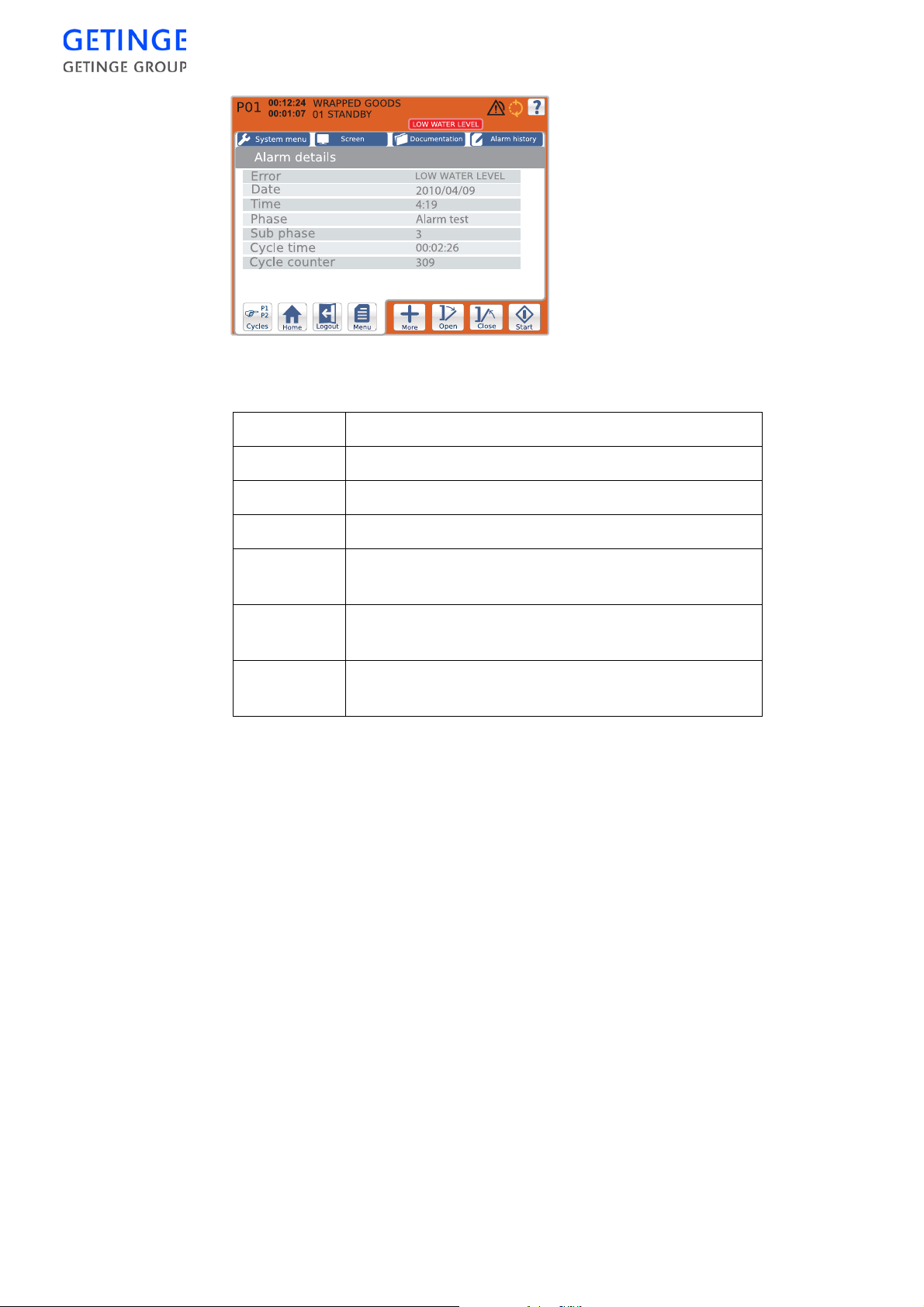
The following alarm information is displayed:
Error Description of the alarm.
Date The date when the alarm triggered.
Time The time when the alarm triggered.
Phase The phase that was current when the alarm triggered.
Sub-phase The sub-phase that was current when the alarm
triggered.
Cycle time Specifies how long the cycle had been going on when
the alarm triggered.
Reset counter The number of cycles executed when the alarm
triggered.
64 -
CONTROL UNIT
Page 69
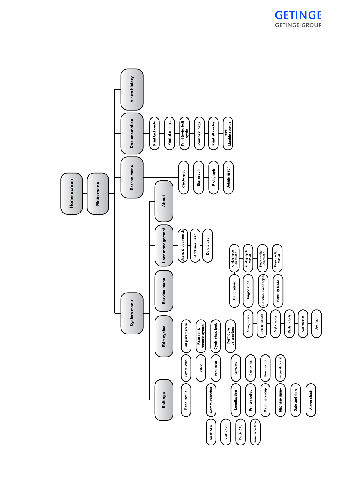
System menu Avanti
A password is required for access to the menu. Those menus that do not
require a password are described in the Operator Menu Avanti section.
CONTROL UNIT -
65
Page 70
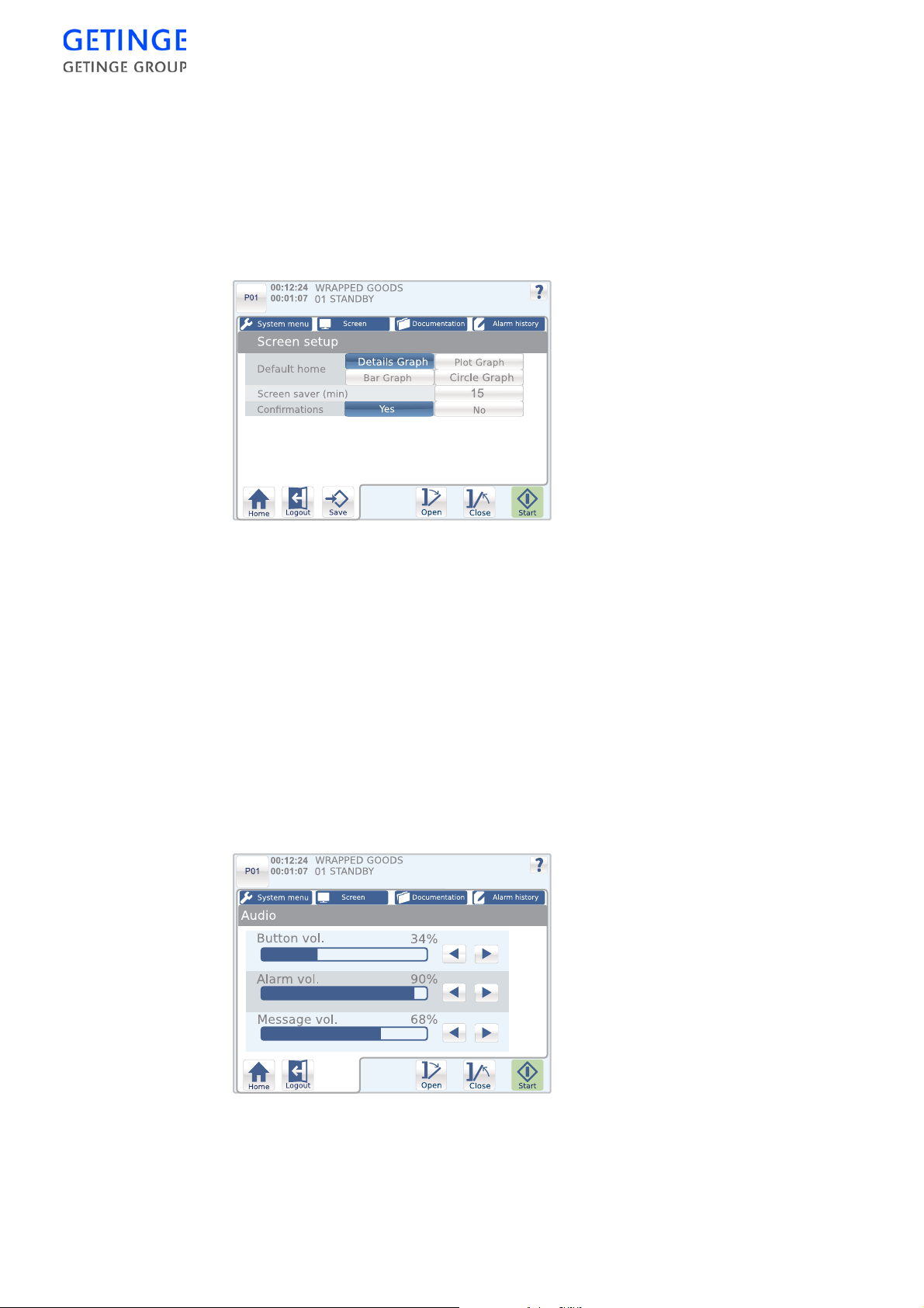
Settings
Panel setup
Screen setup
Here it is possible to select the standard start screen, the time for the
screen saver, as well as pop-up windows for confirming that a saved
value is to be activated. If Confirmations is activated, you will always
receive a yes/no question asking for confirmation of a selection.
•
To set up the start screen, press the button for the start screen of your
choice.
•
To set up the screen saver, press the button with the screen saver. An
inputting window is displayed for inputting the time. Press
Save
to
store the changes.
•
To set up the “Save confirmations”, press the button with the desired
status.
Press
Save
to save the settings.
Sound
Here the possibility is available of editing the volume of buttons, alarms
and mes-sages.
66 -
CONTROL UNIT
Change the volume level of the respective parameters by using the
arrow buttons.
Page 71
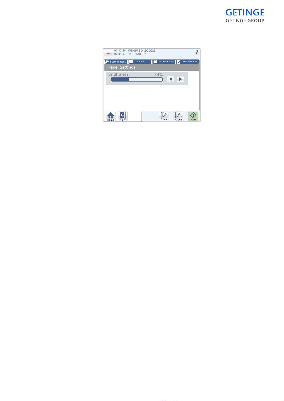
Panel setup
Here it is possible to adjust the brightness of the panel.
Change the brightness by using the arrow buttons.
Communication
Select CPU address
Alist of CPU addresses to communicate with is displayed.
To edit the CPU address, press the button of the desired CPU address.
Press
Save
to save the settings.
Add a CPU address
Here the possibility is available of adding a CPU address.
To add a new CPU address, press on the address button. An inputting
window is displayed for inputting the new address. Press
Save
to add
the new address. Communicating with the new address is automatically
initiated when the address is added.
Press
Save
to save the new address.
Delete CPU address
A list of CPU addresses that may be edited is displayed.
To delete a CPU address, press
Reset panel type
Delete
for the CPU address in question.
Reset panel type involve s changing the panel setting from "Nor mal
mode - PACS 3500/350" (sterilizer) or "Forward mode - PACS 350"
A pop-up window is displayed enquiring whether the panel type should
be reset.
•
Selecting “No” displays the main menu.
•
If you select "Yes", you confirm the selection and after startup,
a list of available panel types is displayed. Select panel type and
confirm your choice.
CONTROL UNIT -
67
Page 72

Localization
A list of the following set-up options is displayed.
•
Language
•
Date format
•
Pressure unit
•
Temperature unit
A list is displayed for each of options above. Press
Printer setup
Printouts are available in the form of a report with all simultaneously
measured values printed on one line , known as logging, and/or in the
form of a graph. Exactly how printouts are composed is determined by
various printing modes.
Different pr in tout modes
Mode 1 An introduction containing batch information is
followed by logging during the cycle.
Mode 2 The printout corresponds to alternative 1, but is
supplemented afterwards by showing the process in the
form of one or more consecutive graphs. It is possible to
define the units used from the operator panel.
Mode 3 In this printout mode, an introduction in the form of
batch information is followed by cycle details in the
form of a graph. The graph is produced in real time,
while the cycle is running, and is concluded at the same
time as the cycle.
Save
to save.
After the graph, activated alarms are also printed out,
together with all measured values at the time of the
alarm.
Storage on disk is not possible for mode 3.
Mode 4 The cycle is drawn in the form of one or more graphs in
parallel with logged measured values. With this mode,
the logging interval should be set to at least 30 seconds
to allow time for the graph to be drawn.
Storage on disk is not possible for mode 4.
68 -
CONTROL UNIT
Page 73
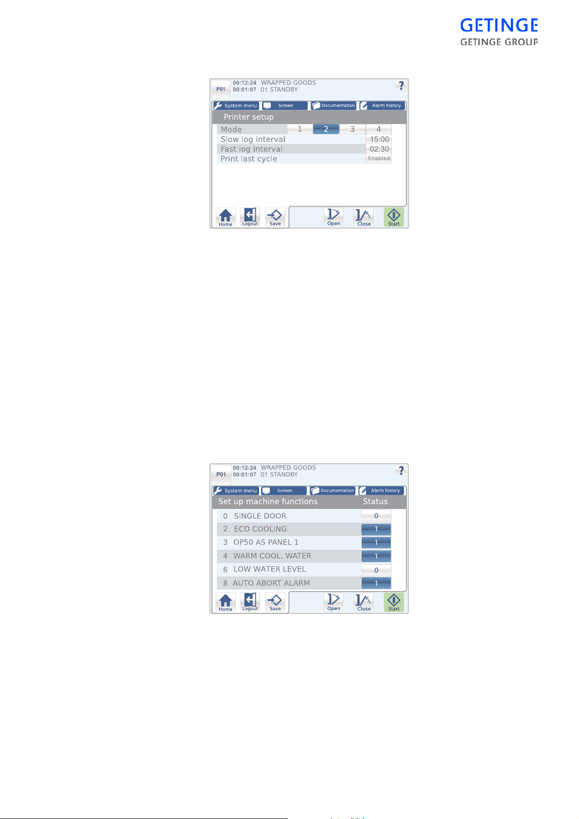
Setting
•
To edit the print mode, mark the desired mode, 1-4.
•
To edit short log intervals, press the time button. An inputting
window is displayed for inputting the desired time. Press
store the time.
•
To edit long log intervals, press the time button. An inputting
window is displayed for inputting the desired time. Press
store the time.
Save
Save
to
to
•
Press the status button to change the status of “Print last cycle".
“Print last cycle” becomes active in the print menu if the function is
activated.
Press
Save
to save the settings.
Machine setup
A list of the available machine functions in the system is displayed.
The machine functions can be turned on or off by pressing the status
button for the machine function of your choice to edit the status.
Press
Save
to save the settings.
CONTROL UNIT -
69
Page 74
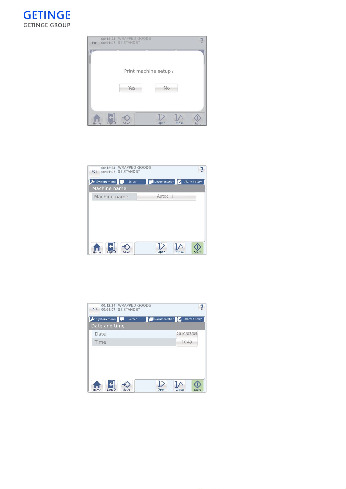
When the settings are saved a pop-up window is displayed. This offers
the possibility of printing the print machine setup.
Machine name
A button with the current machine name is displayed. Press the button
to edit the machine name. An inputting window is displayed for
inputting the desired machine name. Press
Save
to save the name.
Date and time
70 -
CONTROL UNIT
•
To edit the date press the Date button. An inputting win-dow is
displayed for inputting the desired date. Press
Save
to store the date.
Page 75
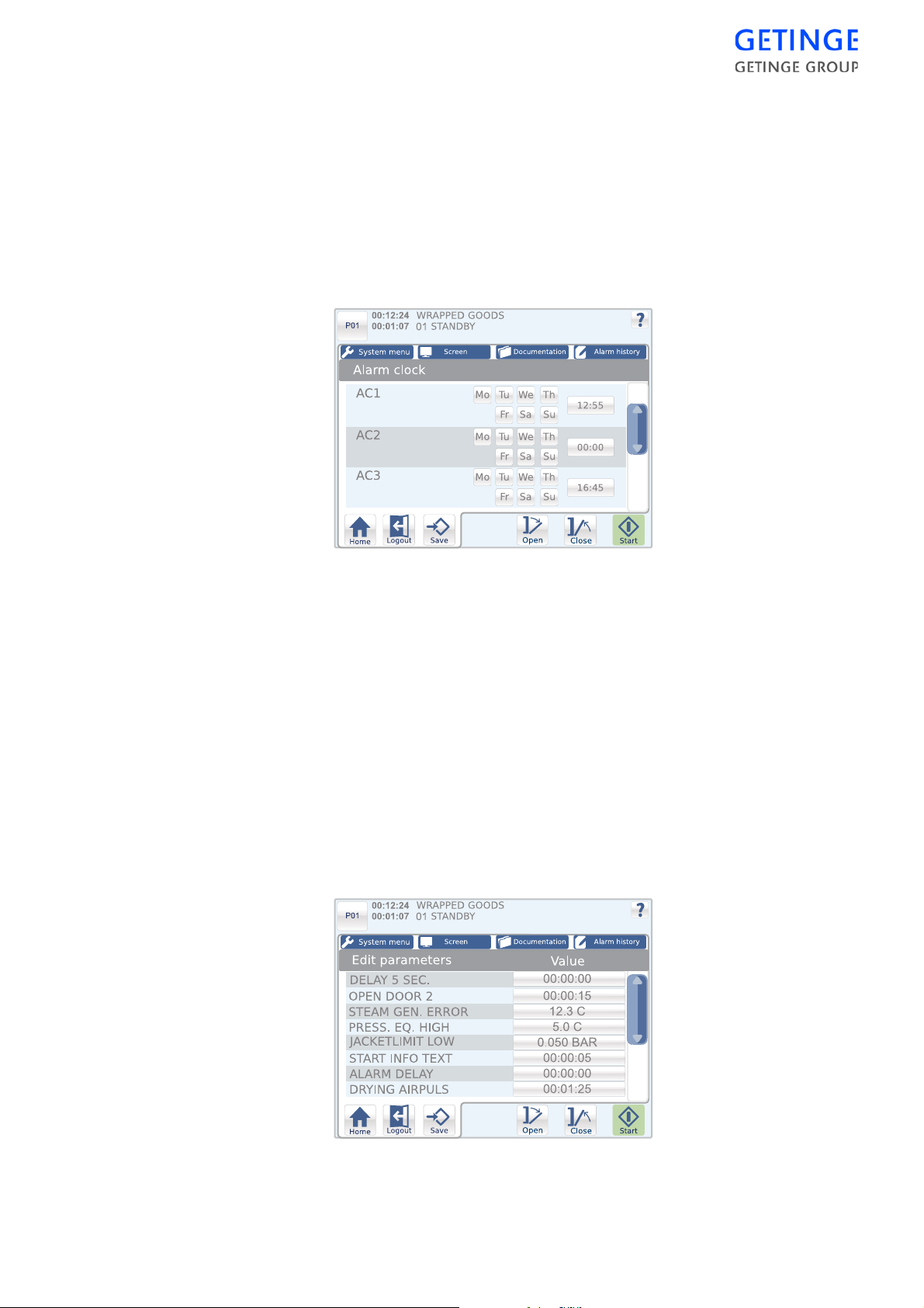
•
To edit the time settings, press the Time button. An inputting
window is displayed for inputting the desired time. Press
store the time.
Press
Save
to save the settings.
Alarm clock
A list of optional alarm clocks that can be set to automatically start at
set times and days of the week is displayed.
Note! No alarm clocks are set in the factory.
Save
to
•
To edit the alarm time settings, press the time button of the desired
alarm clock. An inputting window is displayed for inputting the
desired time. Press
•
For setting up active days of the week, mark the desired day.
Press
Save
to save all settings.
Save
to store the time.
Edit cycles
Note! The function is not available from the unloading side.
Edit parameters
A list of parameters with constant values for a selected cycle is
displayed.
CONTROL UNIT -
71
Page 76
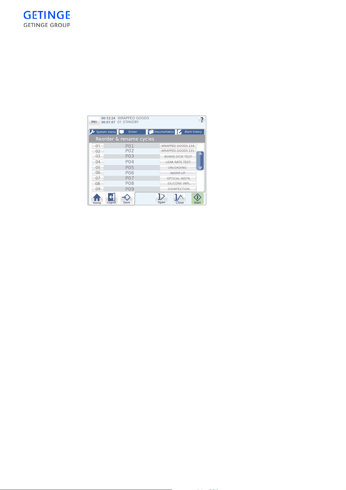
Access is required for reading and editing certain parameters,
depending on which type of parameter the parameter belongs to; see the
section User management.
To edit a parameter, press the button with the parameter value for the
desired parameter. An inputting window is displayed for inputting the
parameter value. Press
Save
to save the edits.
Reorder & rename cycles
A list of available cycles is displayed.
•
To edit the order of the cycles, press the button with the serial
number of the cycle you wish to move. An inputting window is
displayed for inputting new serial numbers. Press
Save
to store the
number. The previous window is again displayed.
Note! Different cycles cannot have the same serial number when the settings
are to be saved.
•
To edit the name of a cycle, press the button with the name of the
cycle. An inputting window is displayed for inputting the new name.
Press
Save
to store the name. The previous window is again
displayed.
Press
Save
to save the settings.
Cycle char. lock
With this function, the first three letters of the cyc le name can be locked
for editing.
A window is shown with the question of whether the lock is to be
activated. Here the alternatives "Yes" or "No" can be chosen. If the
function is already activated, then the question as to whether the button
lock should be activated is displayed instead.
72 -
CONTROL UNIT
Configuring parameters
Setting up whether parameters should be A or P types is done in this
menu, see sectionUser management.
A list of all A and P parameters for the selected cycle is displayed.
Page 77
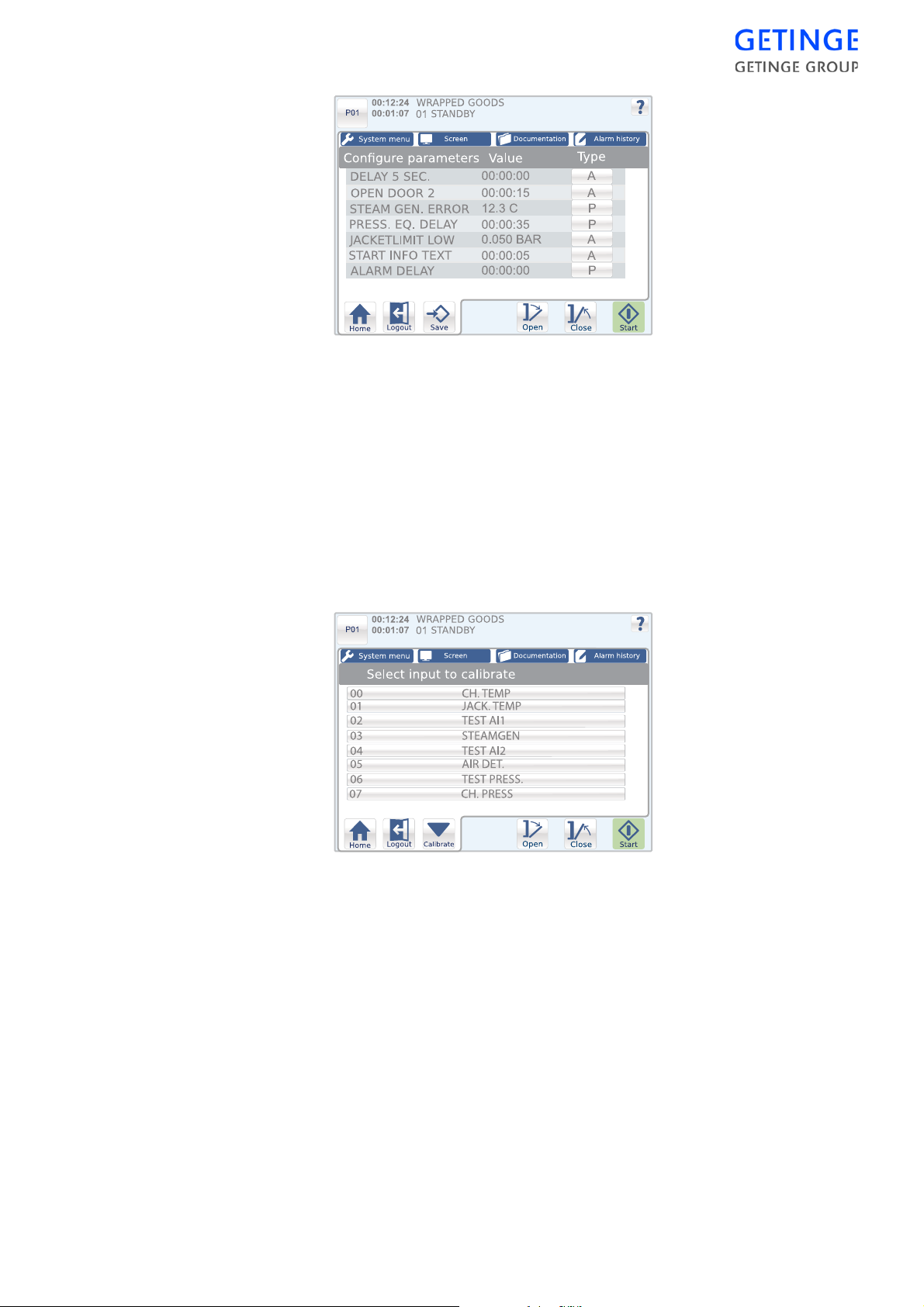
Service
To edit a parameter type, press the button with the parameter type for
the desired parameter.
Press
Save
to save the settings.
Calibration
Analog input – automatic
A list of analog inputs that can be calibrated is displayed.
To calibrate:
1. Mark the inputs to be calibrated and press
Calibrate
.
Note! Only one type of input can be calibrated at a time, i.e., if a temperature
sensor is selected, then no pressure sensor can be selected, and visa
versa.
CONTROL UNIT -
73
Page 78
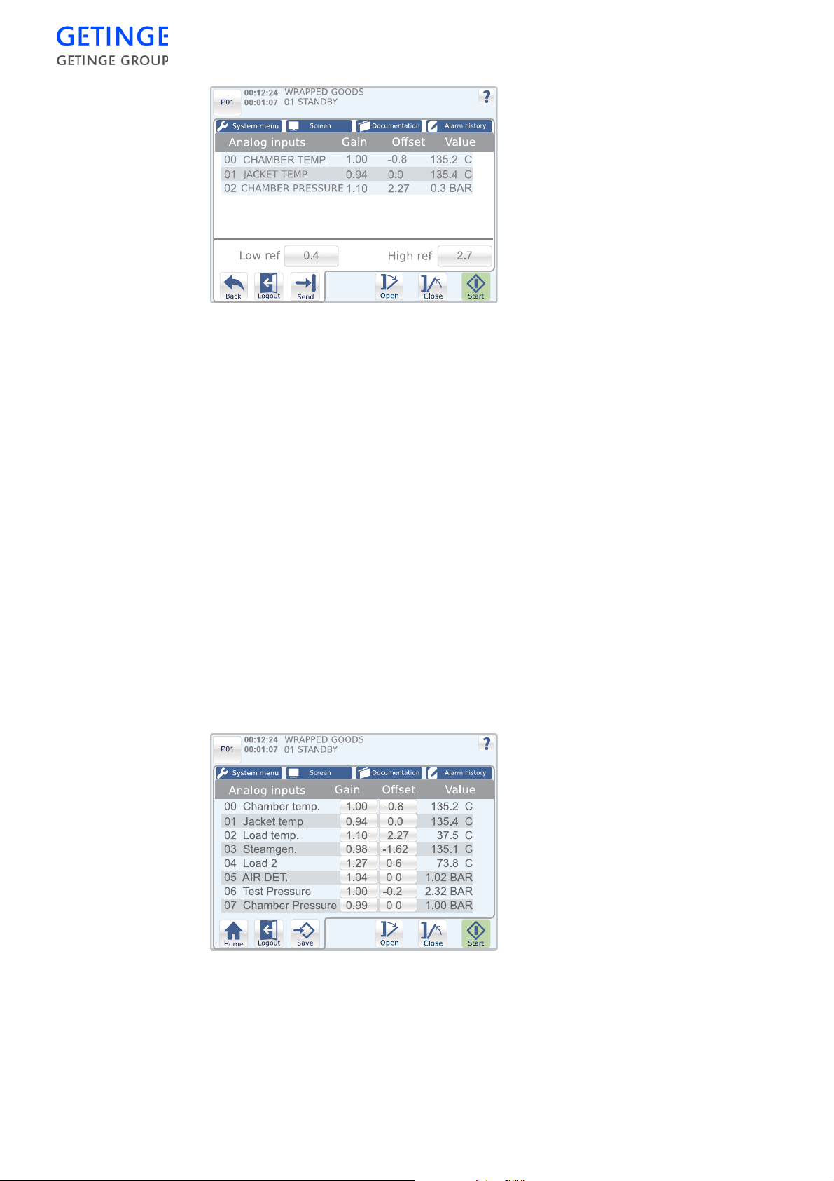
2. It is possible to edit the low and high reference value in a window
that is displayed, along with a scroll list of previously selected
analog inputs and their calibration values.
3. Press the button with the low reference value in order to edit it. An
inputting window is displayed for inputting the reference value.
Press
Save
to save the value. The previous window is again
displayed.
4. Press
Submit
to submit the value to the PACS.
5. Press the button with the high reference value in order to edit it. An
inputting window is displayed for inputting the reference value.
Press
Save
to save the value. The previous window is again
displayed.
6. Press
Save
to calibrate.
7. A pop-up window is displayed where it is possible to print out a
calibration protocol.
Analog input – manual
A list of analog inputs that can be calibrated is displayed.
74 -
CONTROL UNIT
To set the gain or offset for an input, press the button of the value to be
set. An inputting window is displayed for inputting values. Press
Save
to store the value. The previous window is again displayed.
Press
Save
to save the settings.
Page 79
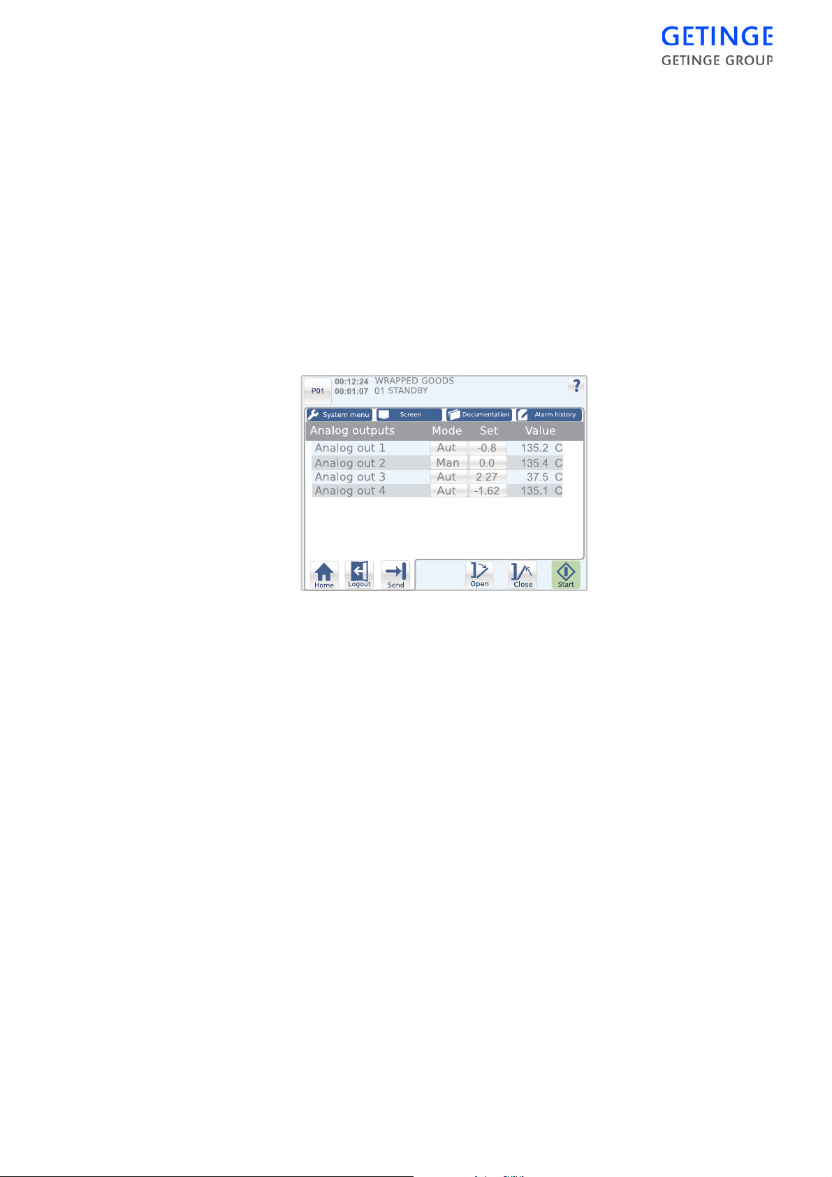
Dose monitor – automatic
The function is not available
Dose monitor – manual
The function is not available
Diagnostics
Analog inputs
A list of current values for the system’s analog inputs is displayed. The
values are continuously updated.
Analog outputs
A list of current values for the system’s analog outputs is displayed. The
values are continuously updated.
The user can choose to set the outputs to the automatic or manual
position.
In automatic mode, the outputs are controlled by the PLC program.
In manual mode, the user c an manually influence the status of the
outputs in both standby mode or during the current process.
•
To change between manual and automatic mode, press the button
with the mode status for the desired output. It is now possible to set
up a value for the output.
•
To set a value, press the button with the value. An inputting window
is displayed for inputting values. Press
•
Press
Submit
Digital inputs
to submit the values to the PACS.
Save
to store the val-ue.
A list of current values for the system’s digital inputs is displayed. The
values are continuously updated.
Digital outputs
A list of the system’s digital outputs is displayed. The values are
continuously updated.
CONTROL UNIT -
75
Page 80
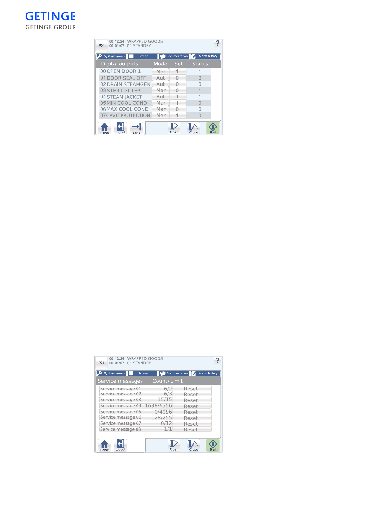
The user can choose to set the outputs to the automatic or manual
position.
In automatic mode, the outputs are controlled by the PLC program.
In manual mode, the user can manually influence the status of the
outputs in both standby mode or during the current process.
•
To change between manual and automatic mode, press the button
with the mode status for the desired output. It is now possible to set
up a value for the output.
•
To set a value, press the button with the value. An in-putting window
is displayed for inputting values. Press
•
Press
Submit
System flags
to submit the values to the PACS.
Save
to store the value.
A list of system flags and their status is displayed.
User flags
A list of user flags in the system is displayed.
Service messages
A list of options for managing service messages is displayed.
Note! No service messages are factory set.
76 -
CONTROL UNIT
Page 81
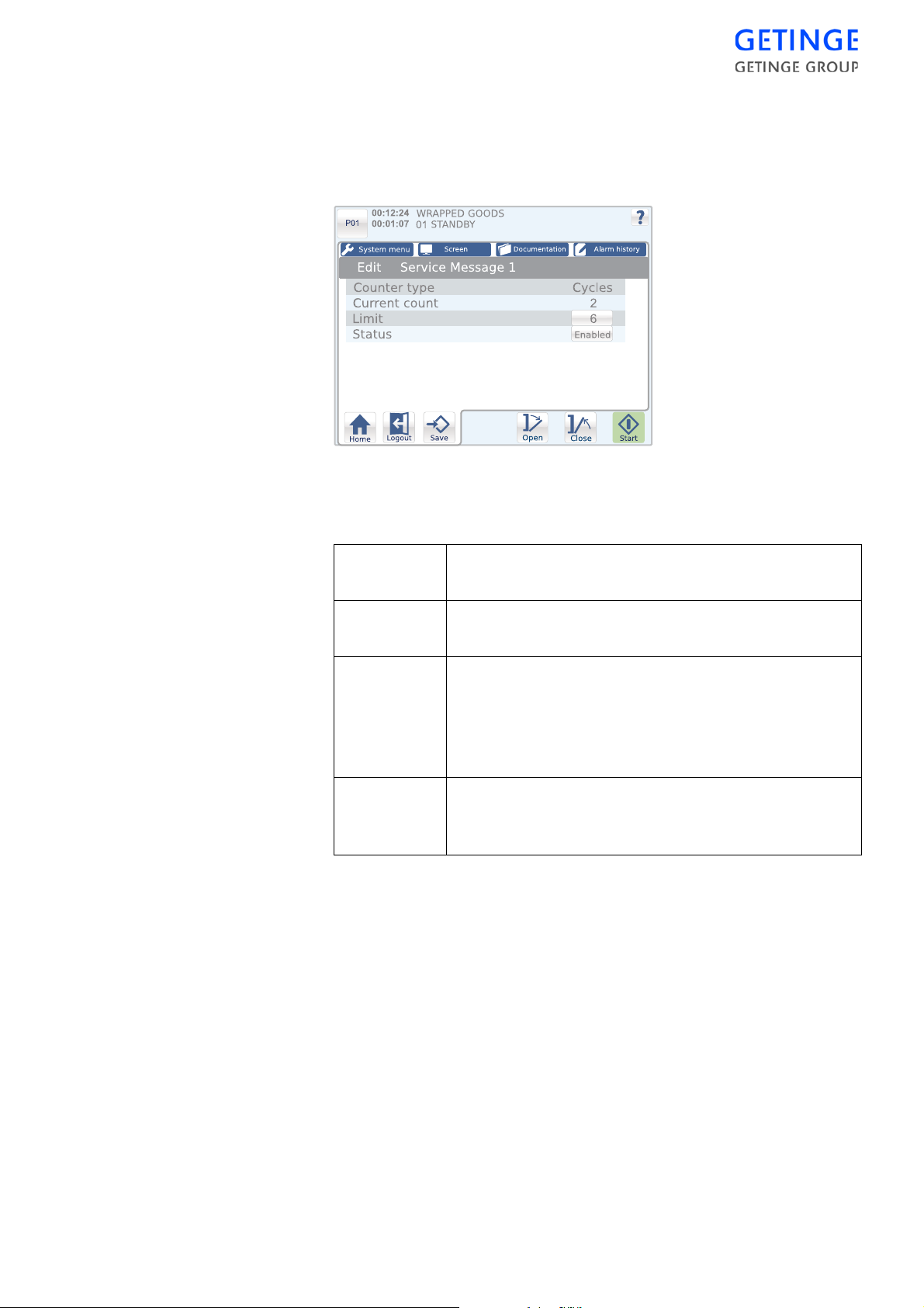
•
To reset the counter for a service message, press
Reset
for the
message in question.
•
To edit one type of service message, press the button for that service
message.
A window is displayed with the following details concerning the service
message:
Type of
counter
Current
number
Displays what type of counter the selected service
message is.
Displays the actual counter value for processes/hours
for the selected service message.
Limit value Specifies, in "stand by" mode, how many processes can
be run before the service message is displayed.
To set the counter limit, press the button for the limit
value. An input window is displayed for inputting a
value. Press
Save
to store the value.
Status Specifies if the service message is activated for display
or not.
To edit the status, press the status button.
Press
Save
to save the settings.
Backup RAM
The menu allows the possibility of saving the content in RAM to a flash
memory.
User management
Users & passwords
A list of users that may be edited is displayed. Only users with the same
or lower access level than those of the current user that is logged in are
displayed.
CONTROL UNIT -
77
Page 82
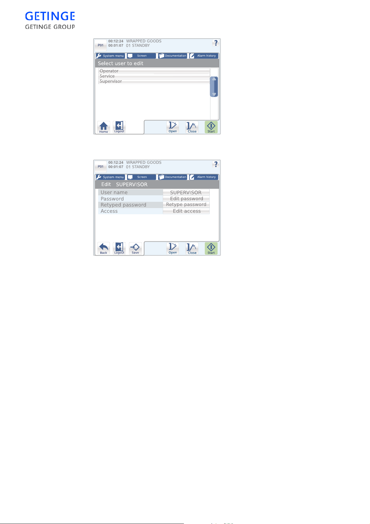
To edit a user, press the button for the user in question.
A window is displayed with parameter s that can be edited for a user.
When the edits have been executed press
•
User name
Save
to save the settings.
To edit the user name, press the button for the user name. An
inputting window is displayed for inputting user names. Press
Save
to store the name.
78 -
CONTROL UNIT
•
Passwords
To edit password, press the
window is displayed for inputting a new password. Press
Edit password
button. An inputting
Save
store the password.
•
Retyped password
To confirm the new password, press the
Retyped password
button.
An inputting window is displayed for inputting the new password.
Press
Save
to confirm.
•
Edit access
To edit the user access rights, press the button for user access rights.
to
Page 83
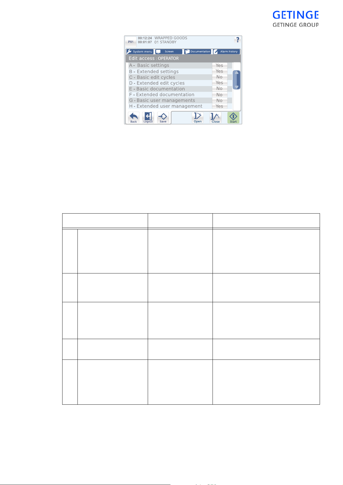
A list of various user access rights is displayed.
To edit the status of a user right, press the status button for the user right
in question.
Press
Save
to save the settings. The user access rights change the next
time the user logs in.
The following table describes what the activated access rights give
access to:
Access User Access available
A Basic settings Department
manager
Service technicians
Programmers
B Extended settings Service technicians
Programmers
C Edit cycles - basic Department
manager
Service technicians
Programmers
D Edit cycles - extended Service technicians
Programmers
E Basic documentation Operator
Department
manager
Service technicians
Programmers
Panel setup
Localization
Machine name
Date & Time
Alarm clock
Print machine setup
Printer setup
Communication
Change parameters
(A parameters *)
Change parameters (P parameters *)
Configure parameters
Print last cycle
Print test page
CONTROL UNIT -
79
Page 84

Access User Access available
F Extended
documentation
G Reorder & rename
cycles
H User access rights Department
I Basic Service Department
J Extended service Service technicians
Department
manager
Service technicians
Programmers
Programmers Reorder & rename cycles
manager
Service technicians
Programmers
manager
Service technicians
Programmers
Programmers
Print alarm list
Print all cycles
Print cycle
Users & passwords
Add new user
Delete user
Analog inputs
Digital inputs
System flags
User flags
Service messages
Calibration
Analog outputs
Digital outputs
Backup RAM
K Password 1 Operator
Department
manager
Programmers
L Password 2 Department
manager
Service technicians
Programmers
M Programming Programmers Cycle char. lock
* The following types of parameters exist:
•
A, adjustable parameters:
Users with access for configuration of cycles are permitted to
edit these parameters.
•
P, programmable parameters.
These parameters are displayed for users with rights to extended
process settings.
•
I, information parameters.
These parameters are displayed for all users, but they are not
allowed to edit them.
Control by Boolean application,
e.g., confirmation or start
Control by Boolean application,
e.g., confirmation or start
80 -
CONTROL UNIT
Page 85
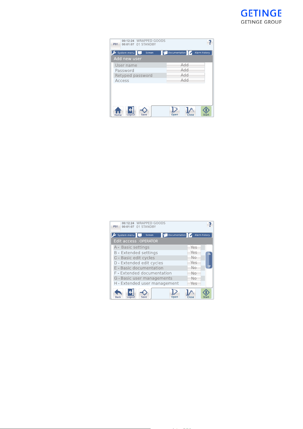
Add new user
To add a new user:
1. To add a user name, press
for inputting user names. Input the name and press
Add
. An inputting window is displayed
Save
. The
previous window is again displayed.
2. To add a user password, press
Add
. An inputting window is
displayed for inputting the password. Input the password and press
Save
. The previous window is again displayed.
3. To confirm a password, press
Add
. A precision inputting window is
displayed for confirming the password. Input the password and
press
Save
. The previous window is again displayed.
4. To add user access rights, press
Add
.
A window with a list of different user access rights is displayed. To edit
the status of a user right, press the status button for the user right in
question. Press
Save
to save the settings. The previous window is again
displayed.
5. Press
Save
to save all settings.
Delete user
A list of users who may be erased is displayed. Only users wit h the same
or lower access level than those of the current user that is logged in are
displayed.
To erase a user, press
Erase
for the user in question.
CONTROL UNIT -
81
Page 86
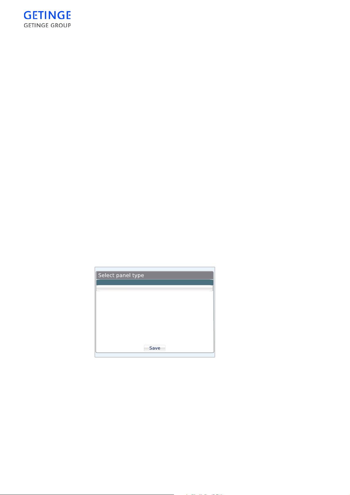
Logged in users cannot be deleted.
About
A list of machine specific data is displayed.
The following information is displayed:
•
Machine name
•
Application version
•
Panel version
•
PACS version
•
PROM date
•
Serial number
•
Total amount of cycles
Startup of new panel
When a new operator panel is mounted on the sterilizer, the menu
"Select panel type" displays at the start. Select the alternative "Normal
mode - PACS 3500/350", and press
If the panel was started earlier, e.g. on production control or receipt
inspection, the menu is not shown.
Save
.
The menu displays also after startup when selecting restart of panel type
(see Reset panel type, in the Communication section).
Normal mode - PACS 3500/350
Forward mode - Only for PACS 350
The "Select CPU addess" menu then displays. Select HS66T or the
program downloaded to the PACS. Press
Save
.
82 -
CONTROL UNIT
Page 87

CONTROL UNIT -
83
Page 88
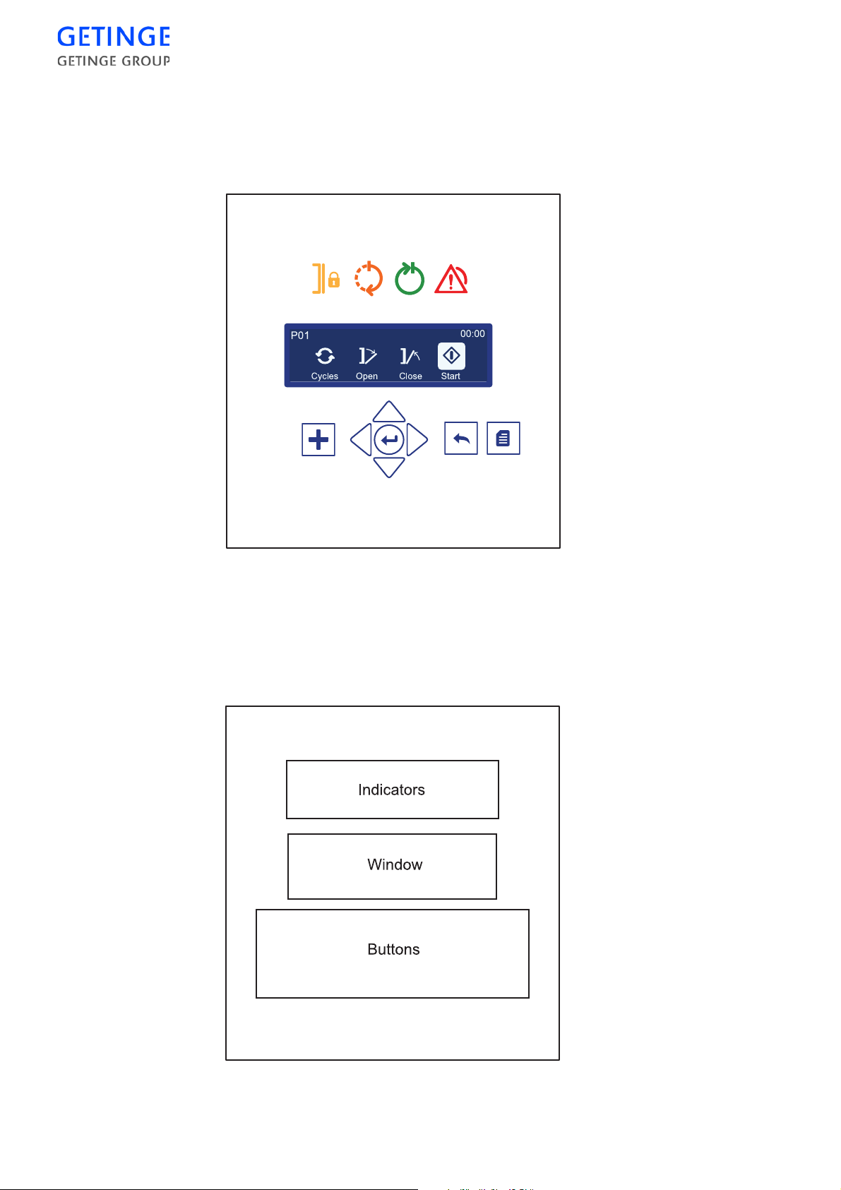
Control panel type Classic
General description
WRAPPED GOODS
Panel
The panel can be divided into three areas: indicators, windows and
buttons.
84 -
CONTROL UNIT
Page 89
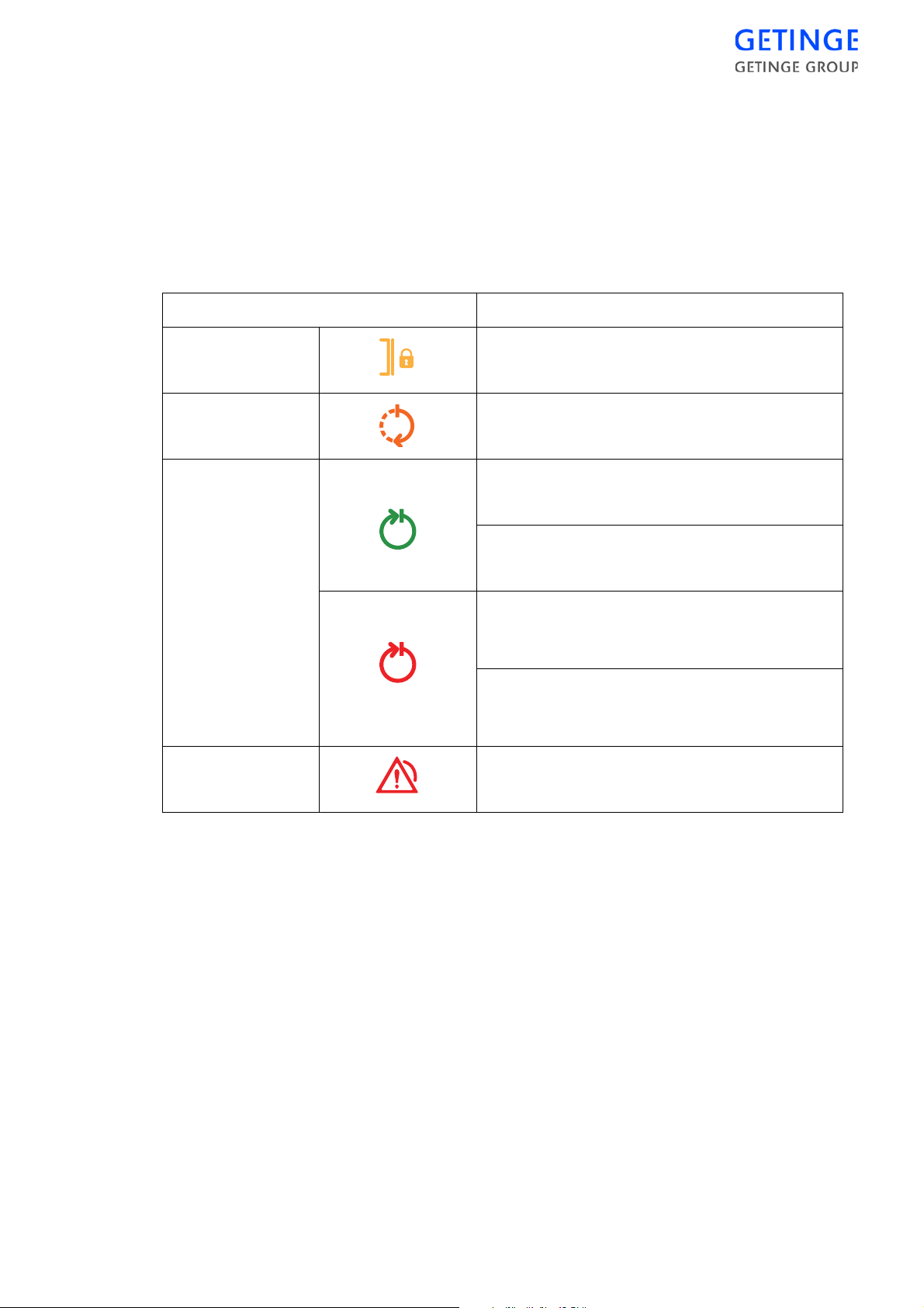
The indicators show the current machine status.
The window shows information about the current cycle and different
menus and functions.
The buttons are used to navigate in the window and select functions.
Indicators
Symbol Description
Doors locked The machine’s doors are closed and locked.
Cycle in progress The machine is processing the selected cycle.
Completed cycle Steady green light: Normal cycle concluded
without warnings or errors.
Flashing green light: Test cycle concluded
without warnings or errors.
Steady red light: Normal cycle concluded, but
a warning and/or error has arisen during
processing.
Flashing red light: Maintenance cycle
concluded, but a warning and/or error has
arisen during processing.
Alarm An alarm has been triggered.
CONTROL UNIT -
85
Page 90
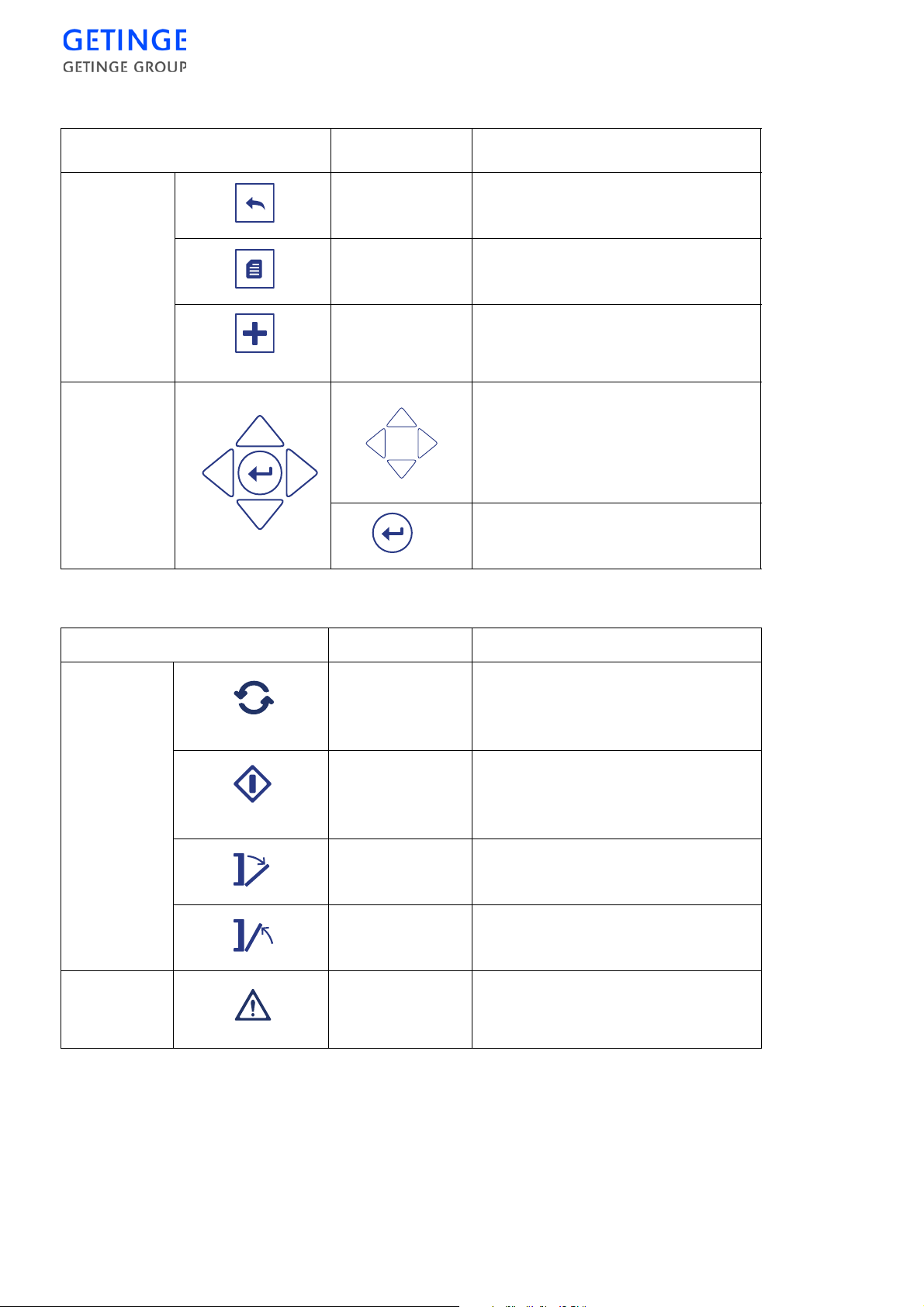
Buttons
Button Operation Description
Navigation
Back
Menu
More
Return to the previous window or
menu, or undo the input.
Return to the main menu.
Optional when alarms or
pre-programmed functions are
active.
Up, Down, Right
arrows
are used for moving the
as well as
Left
cursor and other values on the
screen, also referred to as cursor
keys.
Enter
used for selecting, inputting
or confirming selected modes.
Symbols in window Operation Description
Cyclehandling
Cycles
Open menu to select cycle.
Note: Not displayed on the
unloading side.
Start
Start the selected cycle.
Note: Not displayed on the
unloading side.
Alarmhandling
Open
Close
Alarm An alarm symbol displays if an
Open machine door.
Close machine door.
alarm goes off and is not yet
acknowledged.
86 -
CONTROL UNIT
Page 91
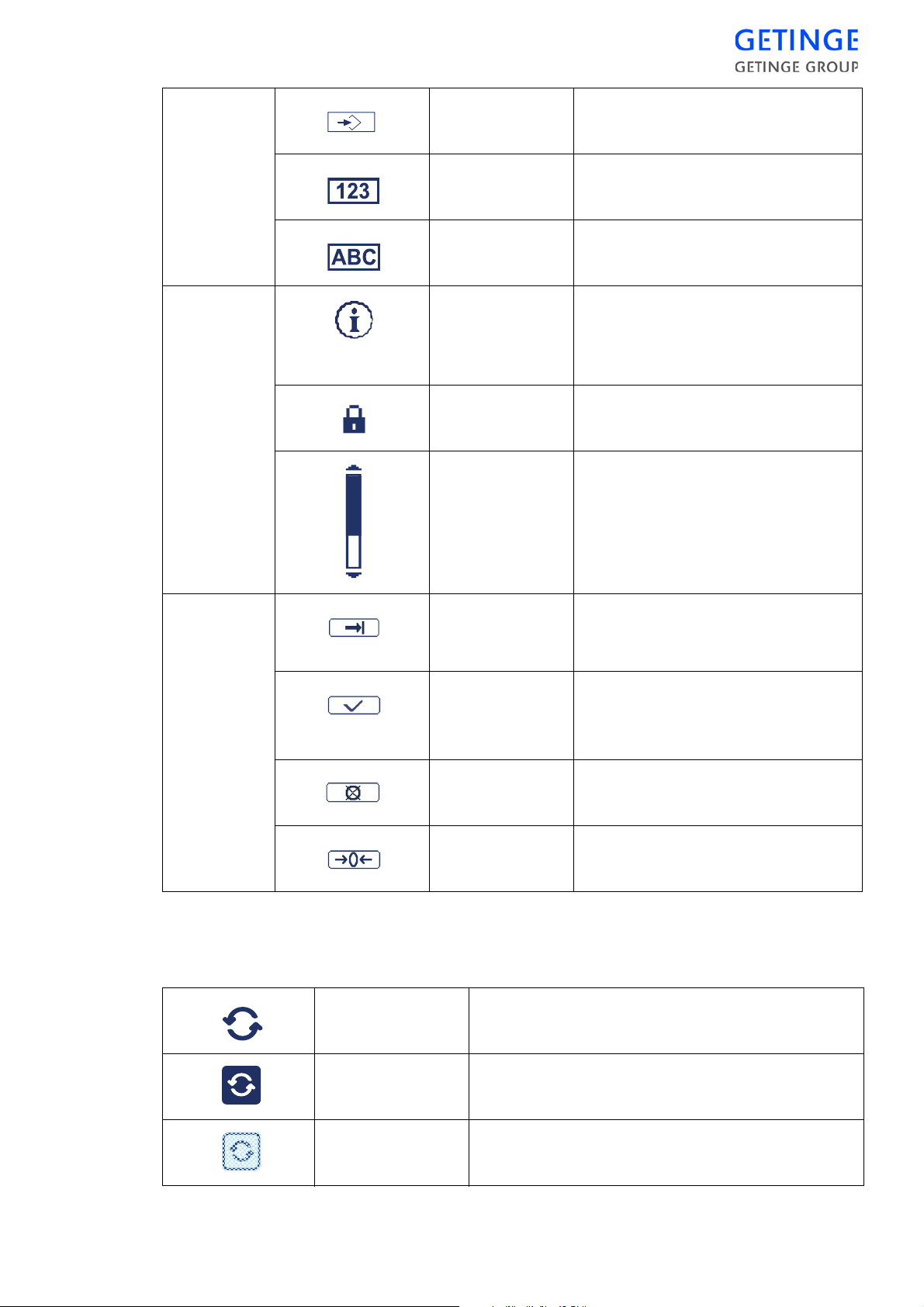
Other
points
Save
Save changes and inputted values.
System
menu
Numeric
keyboard
Alphabetic
keyboard
Shift from alphabetic to numeric
keyboard.
Shift from numerical to
alphabetical keyboard.
Information An incident has occurred. During
the cycle in progress, the whole
infor-mation message is displayed in
the cycle status window.
Inadequate
access
No authorization for access to the
menu.
Scroll list If there are more rows than space
available on the screen, a scroll list
is displayed on the right. To reach
the row above or below, just
continue pressing on the cursor key.
Store/
Continue on
Save inputted value and continue
on to the next value in succession to
be changed.
Edit executed
Abort
Reset edit
The various states of the buttons
Active The button may be pressed but is not marked.
Selected The button is marked.
A value for the field is inputted.
The inputted value may still be
edited.
Reset counter.
Not available The button is currently not available.
CONTROL UNIT -
87
Page 92
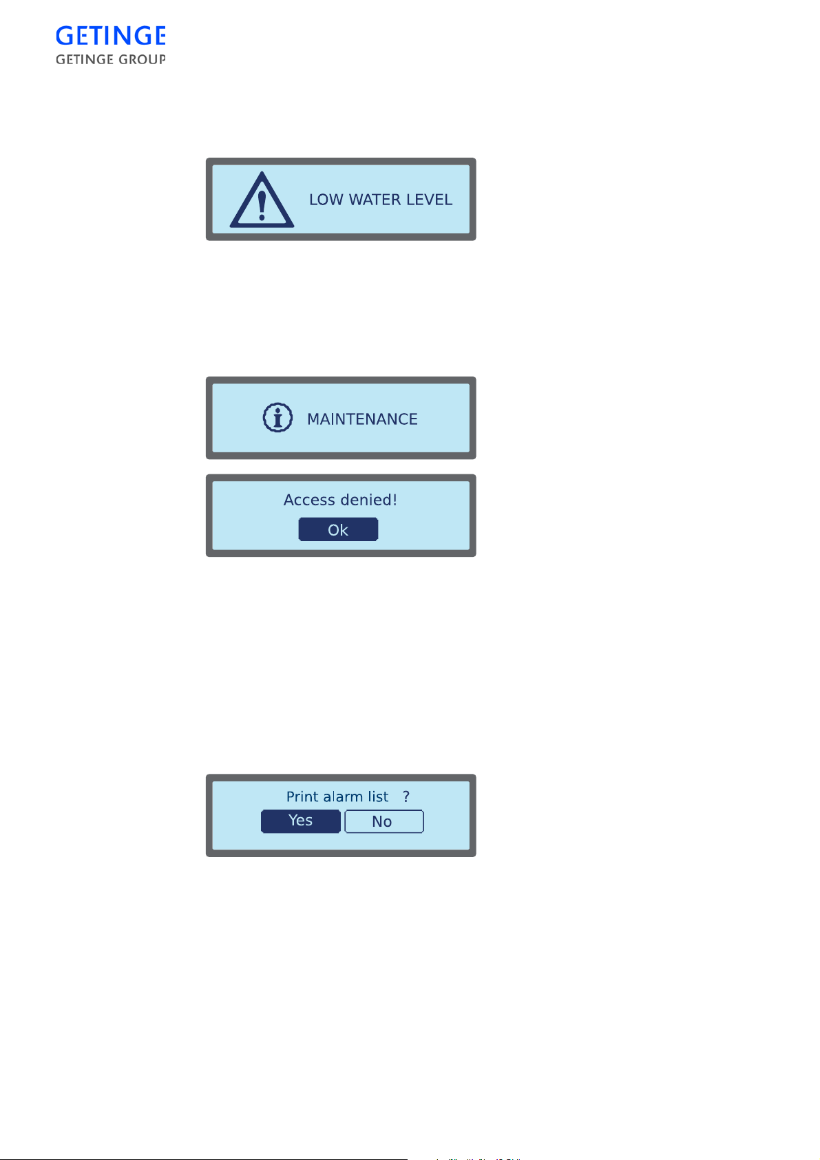
Pop-up windows and dialogue windows
Alarm pop-ups
Shown below is an example of an alarm pop-up.
In the event of an alarm, the current alarm displays as a pop-up window
on the screen and an alarm sounds. For alarm management, see
the“Alarm” section in the chapter Operation in theUSER MANUAL.
Information pop-ups
Shown below is an example of an information pop-up.
Inputting window
Information is automatically displayed on the screen for 3 seconds in
the form of a pop-up window. Then the symbol information is displayed
in the previous screen image.
During a cycle the information report is also displayed in the cycle
status window.
Dialogue window
Shown below is an example of a dialogue pop-up.
The window remains on the screen until a selection is made by pressing
the desired button.
Shown below is an example of an inputting window for various editable
values.
88 -
CONTROL UNIT
Page 93
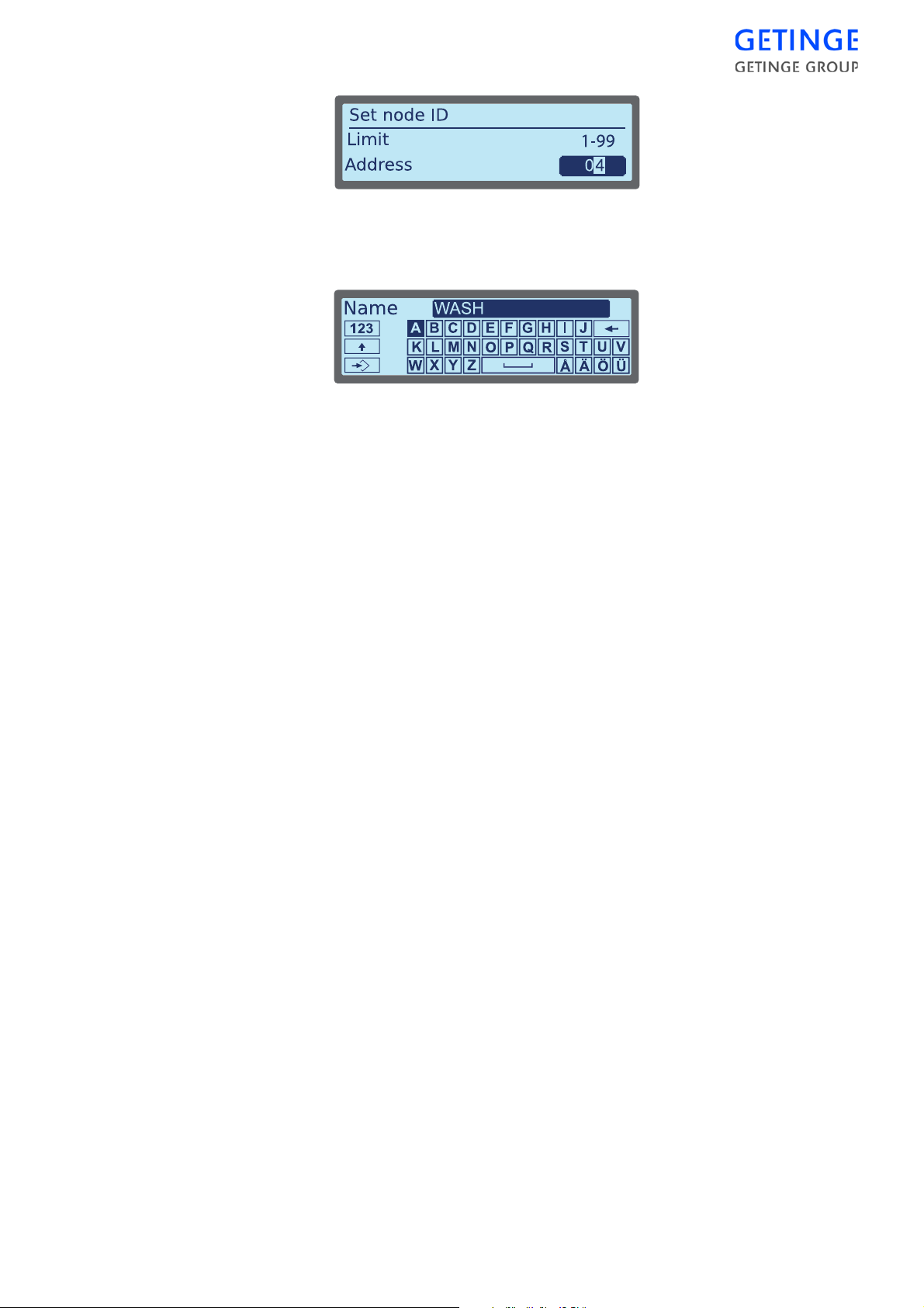
To edit the value, mark the number you wish to edit using the
Left
arrows. Use the Up and
pressing
Enter
.
Down
arrows to edit the number. Save by
Right
and
To enter a name, select the desired letter using the cursor buttons and
press
Enter
to confirm your selection. Select the back arrow farthest to
the right, and press
Enter
to undo the entry.
To toggle between small and capital letters, select the arrow up button
farthest to the left and press
Enter
.
To switch to a numeric keyboard, select the window with numbers
farthest to the left and press
Save the entry by selecting
Enter
.
Save
farthest to the left and press
Enter
.
Different inputting windows exist depending on the input data required.
CONTROL UNIT -
89
Page 94
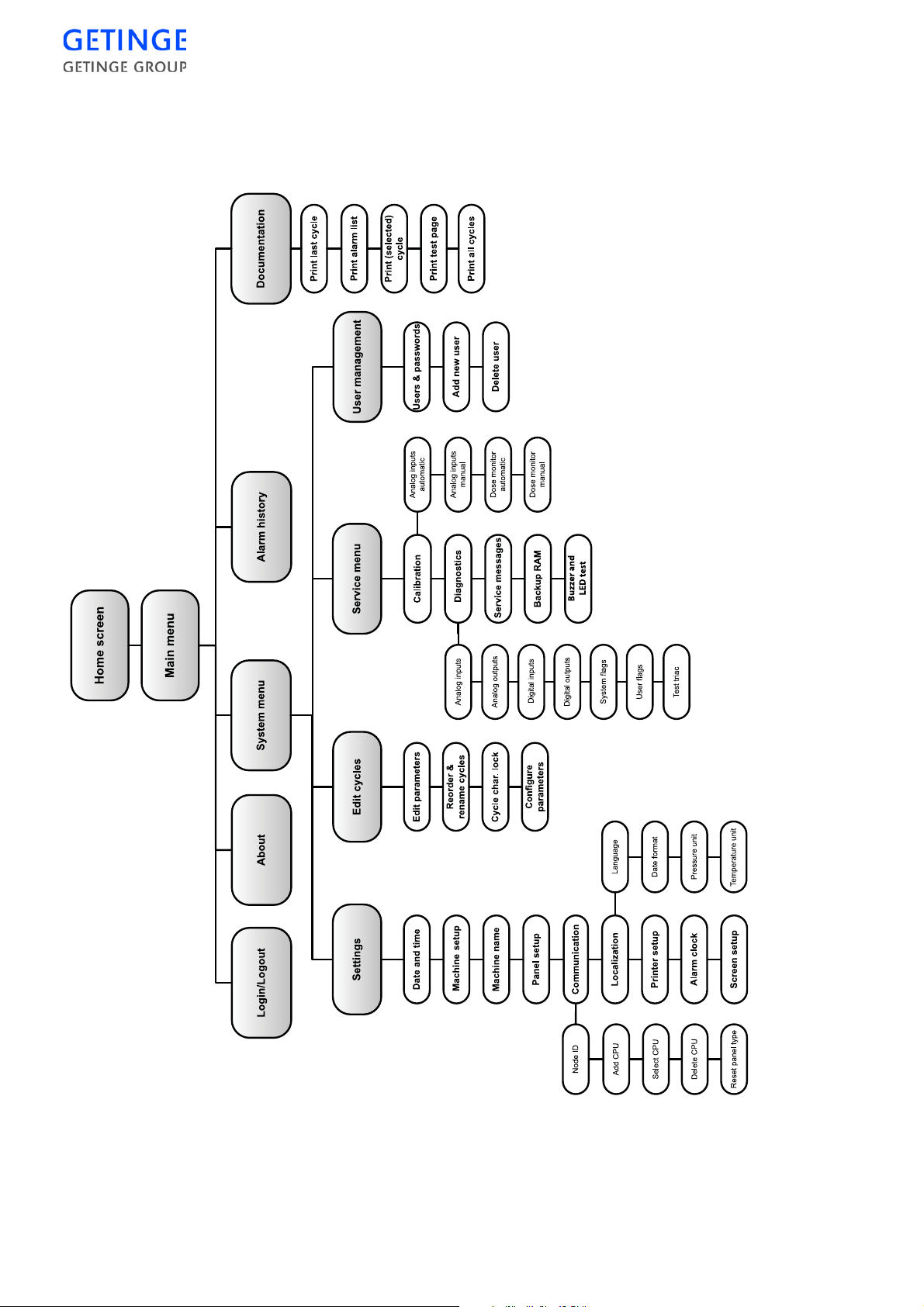
System menu Classic
A password is required for access to the menu. Those menus that do not
require a password are described in the section Operator Menu Classic.
90 -
CONTROL UNIT
Page 95
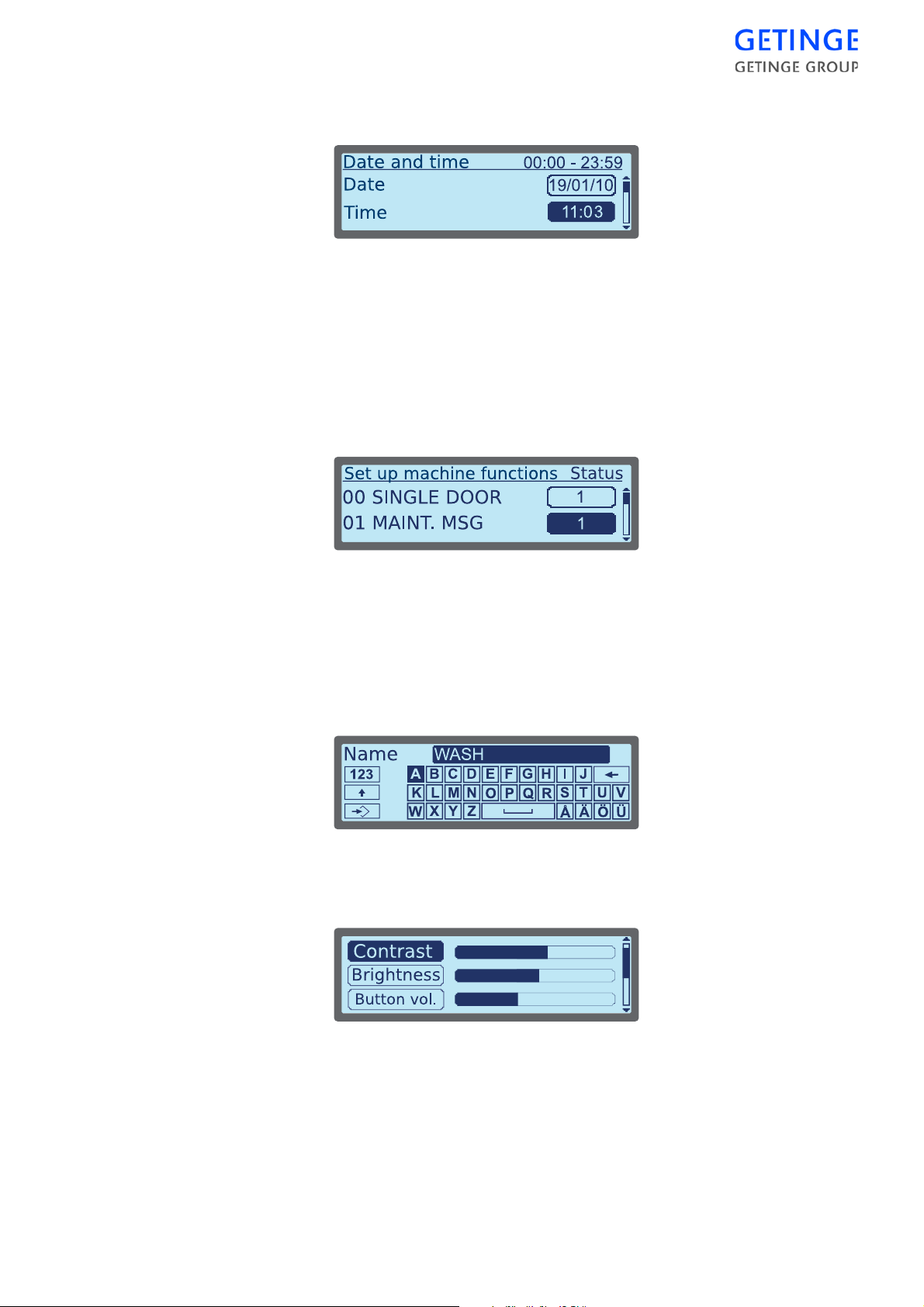
Settings
Date and time
Mark the field to be edited and press
Enter
.
A window is displayed where the selected field can be edited. Edit by
Enter
using the cursor keys. Press
to store the change. The previous
window is again displayed.
Select
Save
at the bottom of the list, and press
Enter
to save the settings.
Machine setup
A list of the available machine functions in the system is displayed.
The machine functions can be turned on or off by marking the desired
machine function and pressing
Select
Save
at the bottom of the list, and press
Enter
to edit the value.
Enter
to save the settings.
When the settings are saved a pop-up window is displayed. This offers
the possibility of printing the machine setup.
Machine name
An inputting window is displayed for inputting the desir ed machine
name. Mark
Save
and press
Enter
to save the name.
Panel setup
A list of the following setting alternatives is displayed.
•
Contrast
•
Brightness
•
Button volume
•
Alarm volume
CONTROL UNIT -
91
Page 96

•
Message volume
Mark the desired parameter and change the level with the
buttons.
Communication
Alist of the following setting alternatives for communication is
displayed.
•
Specify node ID
•
Add a CPU address
For the above selected alternative, a window with an editable field is
displayed. Edit by using the cursor keys. Press
•
Select CPU address
•
Delete CPU address
For the above selected alternative, a list of CPU addresses is displayed.
Mark the CPU address of your choice, and press
•
Reset panel type
A pop-up window is displayed enquiring whether the panel type should
be reset.
•
By selecting “No,” the communication menu is again displayed.
Enter
Enter
Right
and
Left
to store the change.
to select/erase.
•
If you select "Yes", you confirm the selection and after startup,
a list of available panel types is displayed. Select a panel type
and confirm your choice.
Localization
A list of the following setup options is displayed.
•
Language
•
Date format
•
Pressure unit
•
Temperature unit
A list is displayed for each of options above. Mark the desire d option,
and press
Printer setup
Printouts are available in the form of a report with all simultaneously
measured values printed on one line , known as logging, and/or in the
form of a graph. Exactly how printouts are composed is determined by
various printing modes.
Different pr in tout modes
Enter
to save.
92 -
CONTROL UNIT
Mode 1 An introduction containing batch information is
followed by logging during the cycle.
Page 97
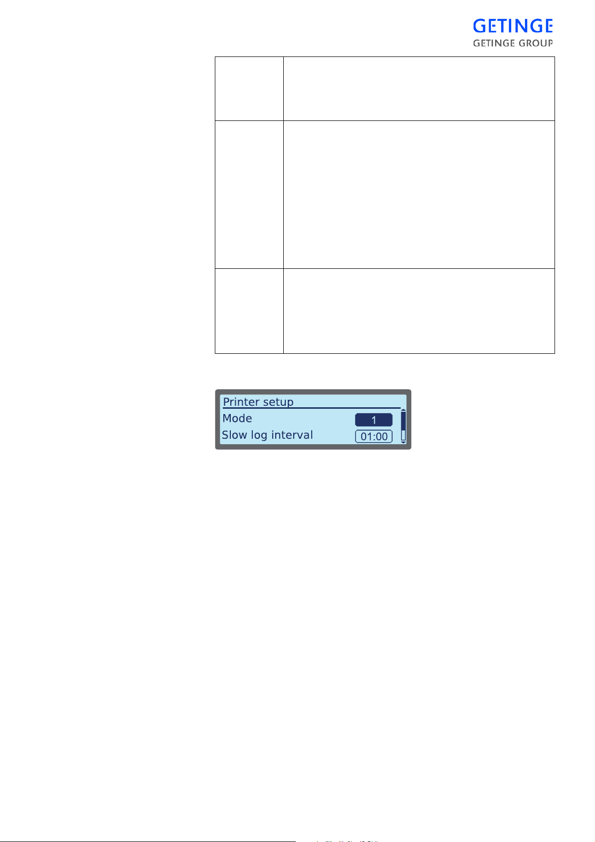
Mode 2 The printout corresponds to alternative 1, but is
supplemented afterwards by showing the process in the
form of one or more consecutive graphs. It is possible to
define the units used from the operator panel.
Mode 3 In this printout mode, an introduction in the form of
batch information is followed by cycle details in the
form of a graph. The graph is produced in real time,
while the cycle is running, and is concluded at the same
time as the cycle.
After the graph, activated alarms are also printed out,
together with all measured values at the time of the
alarm.
Storage on disk is not possible for mode 3.
Mode 4 The cycle is drawn in the form of one or more graphs in
parallel with logged measured values. With this mode,
the logging interval should be set to at least 30 seconds
to allow time for the graph to be drawn.
Storage on disk is not possible for mode 4.
Setting
•
To select a print mode, select the field in front of Mode and press
Enter.
A window is displayed with an editable field for modes. Edit by
Enter
using the cursor keys. Press
to store the change. The previous
window is again displayed.
•
For setting long and short log intervals, mark the value field to be
edited and press
Enter
.
A window is displayed with an editable field for the time interval.
Edit by using the cursor keys. Press
Enter
to store the change. The
previous window is again displayed.
Select
Save
at the bottom of the list, and press
Enter
to save the set-tings.
Alarm clock
A list of optional alarm clocks that can be set to automatically start at
set times and days of the week is displayed.
Note! No alarm clocks are set in the factory.
CONTROL UNIT -
93
Page 98
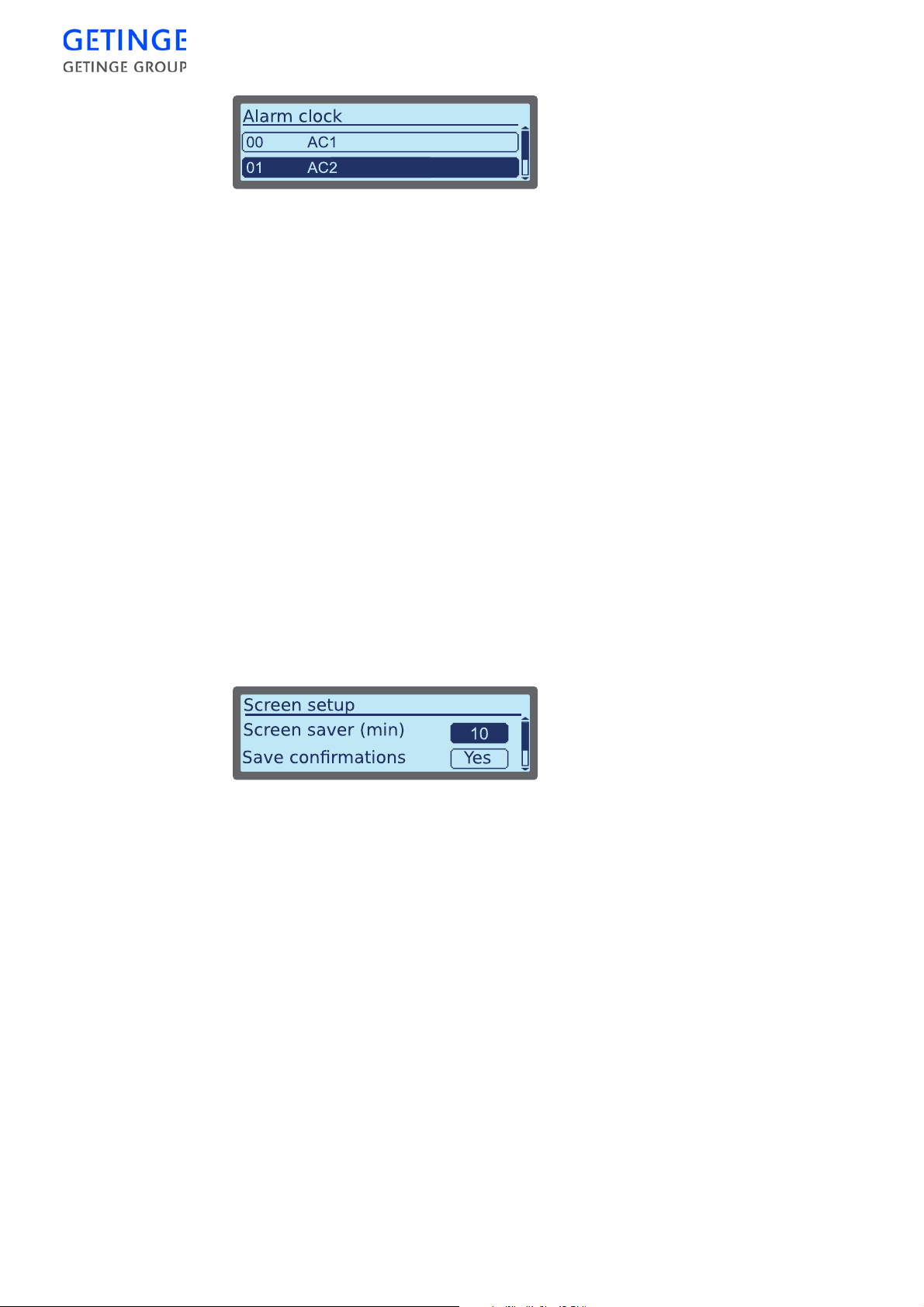
Mark the desired alarm clock, and press
Enter
to edit.
A window is displayed with the possibility of setting an alarm time and
selecting the day of the week for activation of the alarm.
•
To set an alarm time, mark the alarm time and press
Enter
.
A window is displayed with an editable field for the alarm time. Edit
by using the cursor keys . Press
Enter
to store the change. The
previous window is again displayed.
•
For setting up the active day of the week, mark
press
Enter
.
Store/Continue
and
A window is displayed with a list of the days of the week. Mark the
status field with the day of your choice, and change the status by
pressing
Enter
. Select
Save
at the bottom of the list, and press
Enter
to save the changes. The previous window is again displayed.
Select
Save
at the bottom of the list, and press
Enter
to save the settings.
Screen setup
Here it is possible to set up the time for t he screen saver as well as popup windows for confirming that a saved value is to be activated. If
Confirmations is activated, you will always receive a yes/no question
asking for confirmation of a selection.
•
To set up the screensaver mark the time field and press
Enter
.
A window is displayed with an editable field for setti ng the time. Edit
by using the cursor keys. Press
Enter
to store the change. The
previous window is again displayed.
•
For setting up “Save confirmations”, mark the status field and press
Enter
to change the status.
Select
Save
at the bottom of the list, and press
Enter
to save the settings.
Edit cycle
Note! The function is not available from the unloading side.
Edit parameters
A list of param eters with constant values for the selected cycle is
displayed.
94 -
CONTROL UNIT
Page 99
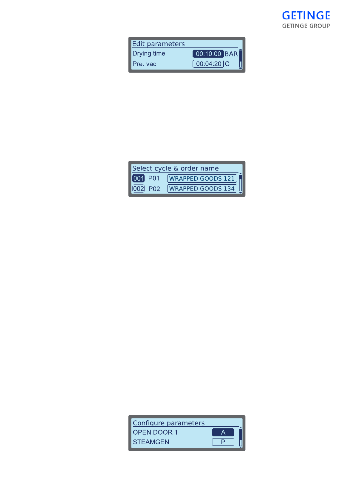
Access is required for reading and editing certain parameters,
depending on which type of parameter the parameter belongs to; see the
section User management.
Enter
To edit a parameter, mark the value field and press
window for inputting the parameter field is displayed. Mark
press
Enter
to save the changes.
. An inputting
Save
and
Reorder & rename cycles
A list of available cycles is displayed.
•
To edit the order of the cycles, mark the button with the serial
number in front of the cycle you wish to move and press
Enter
.
A window is displayed with an editable field for the serial number.
Edit by using the cursor keys. Press
Enter
to store the number. The
previous window is again displayed.
Note! Differen t cycles cannot have the same serial number when the se ttings
are to be saved.
•
To edit the name of a cycle, mark the desired cycle and press
Enter
An inputting window is displayed for inputting the new name. Press
Enter
to store the name. The previous window is again displayed.
Save
Select
at the bottom of the list, and press
Enter
to save the settings.
Cycle char. lock
With this function, the first three letters of the cycle name can be locked
for editing.
A window is shown with the question of whether the lock is to be
activated. Here the alternatives "Yes" or "No" can be chosen. If the
function is already activated, then the question as to whether the button
lock should be activated is displayed instead.
Configuring parameters
Setting up whether parameters should be A or P types is done in this
menu, see sectionUser management.
.
CONTROL UNIT -
95
Page 100
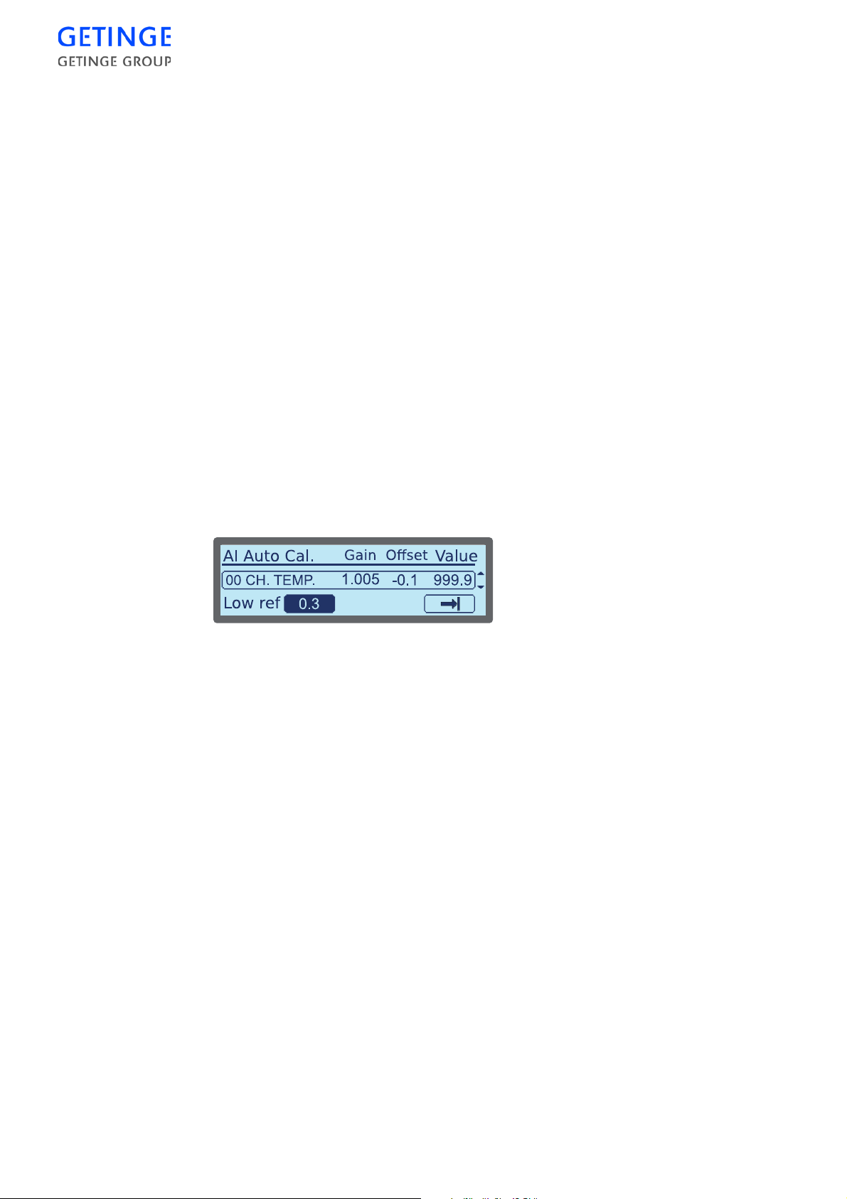
A list of all A and P parameters for the selected cycle is displayed.
Mark the button with the parameter type of your choice, and press
Enter
to edit the parameter type.
Select
Save
at the bottom of the list, and press
Enter
to save the settings.
Service
Calibration
Analog input – automatic
A list of analog inputs that can be calibrated is displayed.
To calibrate:
1. Mark the status field with the input that you wish to calibrate, and
press
Enter
to change the status.
Note! Only one type of input can have “Yes” status, i.e. if a temperature
sensor is selected, then no p ressure sensor can be selected, and visa
versa.
2. Mark
Store/Continue
continue.
at the bottom of the list, and press
Enter
to
3. It is possible to edit the low reference value in a window that is
displayed, along with a scroll list of previously selected analog
inputs and their calibration values.
To browse through the list, mark it and press
possible to browse through the list with the
To edit the low reference value, mark the value and press
Enter
Up
. It is now
and
Down
buttons.
Enter
.
4. A window is displayed with an editable field for the low reference
value. Edit by using the cursor keys. Press
Enter
to store the value.
The previous window is again displayed.
5. Mark
Store/Continue
and press
Enter
to continue.
6. It is possible to edit the low reference value in a window that is
displayed, along with a scroll list of prevously selected analog
inputs and their calibration values.
To browse through the list, mark it and press
possible to browse through the list with the Up and
To edit the high reference value, mark the value and press
Enter
. It is now
Down
buttons.
Enter
.
7. A window is displayed with an editable field for the high reference
value. Edit by using the cursor keys. Press
Enter
to store the value.
The previous window is again displayed.
96 -
CONTROL UNIT
 Loading...