

Page 1
SETUP & OPERATION MANUAL
FEATURES
Large surface, ground cast-iron tables for
stability and added support when feeding
longer stock.
Independent infeed and outfeed table height
adjustment hand wheels.
Precision four point parallelogram table adjustment system allows for easy parallel alignment
of tables to the cutter head and to each other.
Smooth, hand wheel controlled heavyduty rack
and pinion fence positioning.
Heavy-duty closed base steel stand for
maximum stability with built-in wheels.
Magnetic safety switch mounted above the
infeed table for quick, easy access.
6”dust collection outlet included.
Two hand-paddle style push blocks included.
Heavy-duty, three-knife cutter head for clean,
fast, superior finish cuts. (Model 80-325 M1 only)
“Magnum” helical cutter head included.
(Model 80-325HC only)
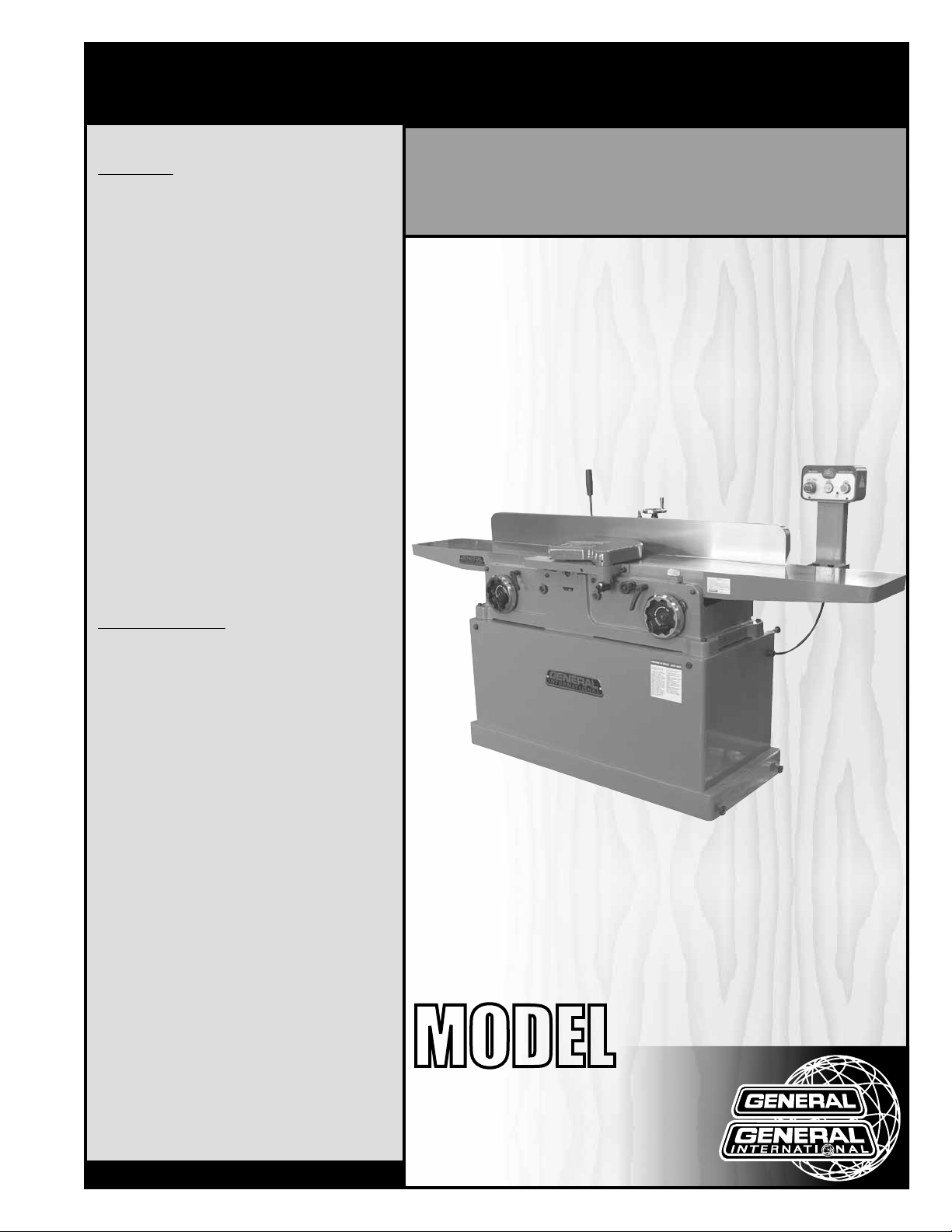
12” PARALLELOGRAM JOINTER
SPECIFICATIONS
• Table size
12” x 87 3/4” (305 x 2229 mm)
• Working height
34 1/2” (876 mm)
• infeed table size
45 7/8” (1165 mm)
• outfeed table size
40” (1016 mm)
• Maximum cutting width
12” (305 mm)
• Maximum cutting depth
3/4” (19 mm)
• Fence size
5 3/8” x 60” (137 x 1524 mm)
• Cutter head speed
5500 rpm
• Dust port diameter
6” (152 mm)
• Base dimensions (l x w)
50 1/2” x 21 1/2” (1283 x 546 mm)
• Overall dimensions (l x w x h)
87 3/4” x 41” x 47 5/8” (2230 x 1042 x 1210 mm)
• Motor M1
5 HP, 220 V, 1 Ph, 23.2 A
• Motor M2
7 1/2 HP, 220 V, 3 Ph, 20 A
• Motor M3
7 1/2 HP, 600 V, 3 Ph, 10 A
• Weight (shipping/net)
1067 lbs (485 kg) / 979 lbs (445 kg)
Version #2 / Revision #1 - April, 2015
© Copyright General International
MODEL
#
80-325
#
80-325HC
Page 2

GENERAL® INTERNATIONAL
8360 Champ-d’Eau, Montreal (Quebec) Canada H1P 1Y3
Telephone (514) 326-1161 • Fax (514) 326-5555 • www.general.ca
THANK YOU
for choosing this General® International model 80-325 M1 /
80-325HC M1 12” jointer. This jointer has been carefully tested and inspected before shipment
and if properly used and maintained, will provide you with years of reliable service. For your
safety, as well as to ensure optimum performance and trouble-free operation, and to get
the most from your investment, please take the time to read this manual before assembling,
installing and operating the unit.
The manual’s purpose is to familiarize you with the safe operation, basic function, and
features of this jointer as well as the set-up, maintenance and identification of its parts and
components. This manual is not intended as a substitute for formal woodworking instruction,
nor to offer the user instruction in the craft of woodworking. If you are not sure about the safety
of performing a certain operation or procedure, do not proceed until you can confirm, from
knowledgeable and qualified sources, that it is safe to do so.
Once you’ve read through these instructions, keep this manual handy for future reference.
DISCLAIMER: The information and specifications
in this manual pertain to the unit as it was supplied
from the factory at the time of printing. Because we
are committed to making constant improvements,
General® International reserves the right to make
changes to components, parts or features of this
unit as deemed necessary, without prior notice and
without obligation to install any such changes on
previously delivered units. Reasonable care is taken
at the factory to ensure that the specifications and
information in this manual corresponds with that of the
unit with which it was supplied. However, special orders
and “after factory”modifications may render some
or all information in this manual inapplicable to your
machine. Further, as several generations of this model
of jointer and several versions of this manual may be in
circulation, if you own an earlier or later version of this
unit, this manual may not depict your unit exactly. If you
have any doubts or questions contact your retailer or
our support line with the model and serial number of
your unit for clarification.
Page 3

GENERAL® INTERNATIONAL WARRANTY
All component parts of General® International and Excalibur by General International® products
are carefully inspected during all stages of production and each unit is thoroughly inspected upon
completion of assembly.
Limited Lifetime Warranty
Because of our commitment to quality and customer satisfaction General® International agrees to
repair or replace any part or component which upon examination, proves to be defective in either
workmanship or material to the original purchaser for the life of the tool. However, the Limited Lifetime
Warranty does not cover any product used for professional or commercial production purposes nor
for industrial or educational applications. Such cases are covered by our Standard 2-year Limited
Warranty only. The Limited Lifetime Warranty is also subject to the “Conditions and Exceptions” as listed
below.
Standard 2-Year Limited Warranty
All products not covered by our lifetime warranty including products used in commercial, industrial
and educational applications are warranted for a period of 2 years (24 months) from the date of
purchase. General® International agree to repair or replace any part or component which upon
examination, proves to be defective in either workmanship or material to the original purchaser during
this 2-year warranty period, subject to the “conditions and exceptions” as listed below.
To file a Claim
To file a claim under our Standard 2-year Limited Warranty or under our Limited Lifetime Warranty,
all defective parts, components or machinery must be returned freight or postage prepaid to
General® International, or to a nearby distributor, repair center or other location designated by
General® International. For further details call our service department at 1-888-949-1161 or your local
distributor for assistance when filing your claim.
Along with the return of the product being claimed for warranty, a copy of the original proof of
purchase and a “letter of claim” must be included (a warranty claim form can also be used and can
be obtained, upon request, from General® International or an authorized distributor) clearly stating the
model and serial number of the unit (if applicable) and including an explanation of the complaint or
presumed defect in material or workmanship.
CONDITIONS AND EXCEPTIONS:
This coverage is extended to the original purchaser only. Prior warranty registration is not required but
documented proof of purchase i.e. a copy of original sales invoice or receipt showing the date and
location of the purchase as well as the purchase price paid, must be provided at the time of claim.
Warranty does not include failures, breakage or defects deemed after inspection by
General® International to have been directly or indirectly caused by or resulting from; improper use,
or lack of or improper maintenance, misuse or abuse, negligence, accidents, damage in handling or
transport, or normal wear and tear of any generally considered consumable parts or components.
Repairs made without the written consent of General® International will void all warranty.
Page 4

TABLE OF CONTENTS
Rules for safe operation ............................ 5
Additional Safety Instructions
for jointers ................................................. 6
Electrical requirements ............................. 7
Electrical connections ............................................. 7
Grounding instructions ............................................ 7
Circuit capacity ....................................................... 7
Extension cords ........................................................ 7
Identification of main parts
and components ....................................... 8
Basic functions .......................................... 9
Unpacking ................................................ 9
List of contents .......................................................... 9
Additional requirements for set up ........................ 9
Adjusting the fence and setting
the fence stops ................................... 13-14
Operating instructions ....................... 14-16
Connecting to a dust collector ............................ 14
Basic principles of jointing .................................... 14
Selecting boards suitable for jointing ................. 15
Determine the concave face
and edge of your board ...................................... 15
Adjust fence front to back position ..................... 15
Checklist before starting ....................................... 15
Connecting to a power source ............................ 16
Magnetic safety switch ......................................... 16
Basic jointing operations ........................ 16
Face jointing ........................................................... 16
Edge jointing .......................................................... 17
Rabbeting ............................................................... 17
Clean up ................................................ 10
Placement within the shop /
safety zone .............................................. 10
Placement within the shop ................................... 10
Establishing a safety zone ..................................... 10
Assembly instructions ............................. 11
Reposition the switch post .................................... 11
Install the cutter head guard ................................ 11
Adjusting and setting the outfeed
table height ............................................. 12
Adjusting and setting the infeed table
height / depth of cut ......................... 12-13
Table alignment ..................................................... 13
Checking / adjusting the zero point stop
bolt ........................................................................... 13
Maintenance ........................................... 17
Inspecting / replacing cutter head knives .... 17-18
Knife setting / replacement - 80-325 only .... 18-19
Helical cutter head insert reversal /
replacement - 80-325HC only .......................... 19-20
Parallel (co-planar) alignment
of the infeed and outfeed tables .................... 20-22
Periodic maintenance .......................................... 22
Adjusting the infeed table
zero point and down stops .............................. 22-24
Recommended optional accessories .... 25
Parts list & diagrams .......................... 26-31
Contact information ............................... 32
Page 5

RULES FOR SAFE OPERATION
To help ensure safe operation, please take a moment to learn the machine’s applications and limitations,
as well as potential hazards. General
harmless for any injury that may result from the improper use of it’s equipment.
1. Do not operate this jointer when tired, distracted,
or under the effects of drugs, alcohol or any me dication that impairs reflexes or alertness.
2. The work area should be well lit, clean and free
of debris.
3. Keep children and visitors at a safe distance when
the jointer is in operation; do not permit them to
operate the jointer.
4. Childproof and tamper proof your shop and all
machinery with locks, master electrical switches
and switch keys, to prevent unauthorized or unsu pervised use.
5. STAY ALERT! Give your work your undivided attention.
Even a momentary distraction can lead to serious
injury.
6. Fine particulate dust is a carcinogen that can be
hazardous to health. Work in a well-ventilated area
and whenever possible use a dust collector. Wear
face, eye, ear, respiratory and body protection
devices.
®
International disclaims any real or implied warranty and holds itself
12. If using a power feeder, stop the feeder before
stopping the jointer.
13. Do not push or force stock into the cutter head. The
jointer will perform better and more safely when
working at the rate for which it was designed.
14. Be sure that the cutter head has gained full opera ting speed before starting to joint.
15. Avoid working from awkward or off balance posi tions. Do not overreach and keep both feet on floor.
16. Keep guards in place and in working order. If a
guard must be removed for maintenance or clean ing be sure it is properly re-attached before using
the tool again.
17. Use of parts and accessories NOT recommended
by General
malfunction or risk of injury.
18. Never stand on machinery. Serious injury could
result if the tool is tipped over or if the cutting tool is
unintentionally contacted.
®
International may result in equipment
7. Do not wear loose clothing, gloves, bracelets, neck- laces or other jewelry while the jointer is in opera tion. Wear protective hair covering to contain long
hair and wear non-slip footwear.
8. Be sure that adjusting wrenches, tools, drinks and
other clutter are removed from the machine and/or
the table surface before operating.
9. Keep hands well away from knives and all moving
parts. Use a push stick to feed stock, and a brush,
not hands, to clear away chips and dust.
10. Be sure that the knives are securely installed in the
cutter head.
11. Always use clean, properly sharpened knives.
Dirty or dull knives are unsafe and can lead to
accidents.
19. Always disconnect the tool from the power source
before servicing or changing accessories such as
knives, or before performing any maintenance or
cleaning, or if the machine will be left unattended.
20. Make sure that the switch is in the “OFF” position be- fore plugging in the power cord.
21. Make sure the tool is properly grounded. If equip ped with a 3-prong plug it should be used with
a three-pole receptacle. Never remove the third
prong.
22. Do not use this jointer for any purpose other than
its intended use. If used for other purposes, General
International disclaims any real or implied warranty
and holds itself harmless for any injury, which may
result from that use.
®
5
Page 6

ADDITIONAL SAFETY INSTRUCTIONS FOR JOINTERS
Because each shop situation is unique, no list of safety guidelines can ever be complete. The
most important safety feature of any shop is the knowledge and good judgement of the user. Use
common sense and always keep safety considerations, as they apply to your individual shop
conditions, first and foremost in mind. If you have any doubts about the safety of an operation you
are about to perform: STOP! Do not perform the operation until you have validated from qualified
individuals if the operation is safe to perform and what is the safest method to perform it.
WORK PIECE KICKBACK
Kickback is when the work piece is ejected at
high speeds from the jointer table by the force of
the cutter head. To minimize the risk of injury from
kickback, always use push blocks and wear safety glasses. Do not operate this machine if you do
not understand kickback, its causes and how to
avoid it.
CUTTER HEAD ALIGNMENT
To reduce the risk of injury and to avoid kickback,
keep the top edge of the outfeed table aligned
with the top dead center edge of the knife.
PUSH BLOCKS
Always use push blocks when jointing. Never pass
your bare hands directly over the cutter head
without a push block to hold and guide the workpiece.
WORKPIECE SUPPORT
To make safe cuts and reduce the risk of injury,
support the workpiece adequately at all times.
Never attempt to make a cut with an unstable
workpiece.
KICKBACK ZONE
The kickback zone on a jointer is the area directly
in the path through and off of the end of the infeed table. Never stand or allow others to stand in
this area during operation.
MAXIMUM DEPTH OF CUT
The maximum depth of cut for one pass is 1/8”.
Never attempt to remove more material than 1/8”
in any single pass.
JOINTING WITH THE GRAIN
Jointing against the grain or jointing end grain is
dangerous and could produce chatter or excessive chip out. Always joint with the grain.
KEEPING GUARDS IN PLACE
Except when rabbeting, all operations must be
performed with the guard in place. After rabbeting, be sure to replace the guard.
PROPER CUTTING
Always move the work piece over the cutter head
from the infeed table towards the outfeed table
until the work piece has passed completely over
the cutter head. Never back the work piece towards the infeed table.
USING GOOD WORK PIECE STOCK
Jointing safety begins with the stock used with the
machine. Inspect the work piece carefully before
jointing it. Never joint a board that has loose knots,
staples, nails or other embedded foreign objects.
If you have the slightest doubt about the structural
integrity or stability of a board: Do Not Joint It.
6
Page 7
ELECTRICAL REQUIREMENTS
BEFORE CONNECTING THE MACHINE TO THE POWER SOURCE, VERIFY THAT THE VOLTAGE OF YOUR POWER
SUPPLY CORRESPONDS WITH THE VOLTAGE SPECIFIED ON THE MOTOR I.D. NAMEPLATE. A POWER SOURCE
WITH GREATER VOLTAGE THAN NEEDED CAN RESULT IN SERIOUS INJURY TO THE USER AS WELL AS DAMAGE
TO THE MACHINE. IF IN DOUBT, CONTACT A QUALIFIED ELECTRICIAN BEFORE CONNECTING TO THE POWER
SOURCE.
THIS TOOL IS FOR INDOOR USE ONLY. DO NOT EXPOSE TO RAIN OR USE IN WET OR DAMP LOCATIONS.
Note: voltage requirements and amperage draw for M2 & M3 3-phase motors may not
be fully described in this manual. For complete electrical requirements refer to the motor I.D. name plate on the machine. If in doubt consult a licensed qualified electrician
before proceeding.
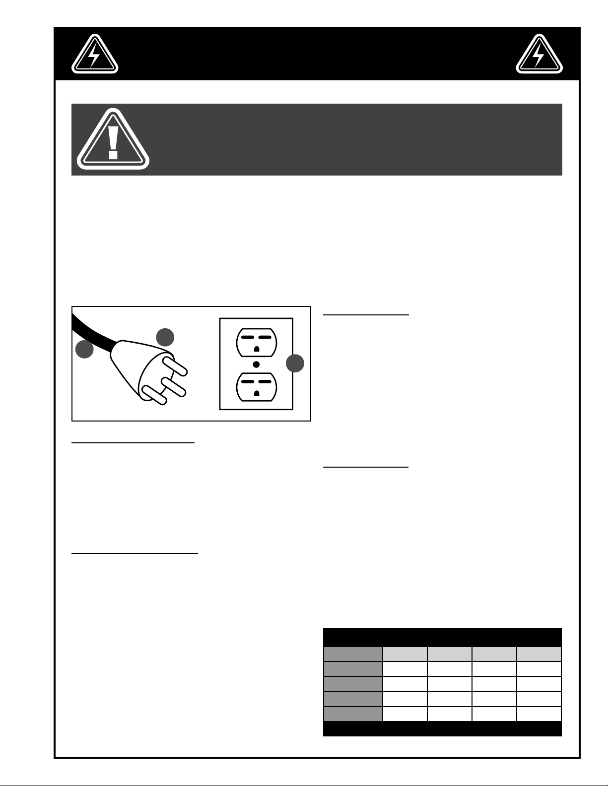
CIRCUIT CAPACITY
Make sure that the wires in your circuit are capable of
B
A
C
ELECTRICAL CONNECTIONS
Both a manual circuit breaker (or similar device) as well
as an electrical plug (similar to the one shown) are recommended and SHOULD BE INSTALLED BY A QUALIFIED
ELECTRICIAN.
Use locally approved wire A that includes a separate
grounding wire and a 3 prong grounding type plug B
with a matching receptacle C.
GROUNDING INSTRUCTIONS
In the event of an electrical malfunction or short circuit,
grounding reduces the risk of electric shock to the operator. The motor of the “M1” model of this machine is
wired for 220V single phase operation.
As with many stationary industrial type machines, because each installation situation is unique, this bandsaw is supplied without a power cord or plug.
The installation of an appropriate power cord and plug
must be performed by a qualified electrician. The machine must be connected to an electrical source using
a power cord that has a grounding wire, which must
also be properly connected to the grounding prong
on the plug. The outlet must be properly installed and
grounded and all electrical connections must be made
in accordance with all local codes and regulations.
handling the amperage draw from your machine, as
well as any other machines that could be operating on
the same circuit. If you are unsure, consult a qualified
electrician.
If the circuit breaker trips or the fuse blows regularly,
your machine may be operating on a circuit that is
close to its amperage draw capacity. However, if an
unusual amperage draw does not exist and a power
failure still occurs, contact a qualified technician or our
service department.
EXTENSION CORDS
The use of an extension cord is not generally recommended for 220V equipment. If you find it necessary,
use only 3-wire extension cords that have 3-prong
grounding plug and a matching 3-pole receptacle that
accepts the tool’s plug. Repair or replace a damaged
extension cord or plug immediately.
Make sure the cord rating is suitable for the amperage listed on the motor I.D. plate. An undersized
cord will cause a drop in line voltage resulting in
loss of power and overheating. The accompanying chart shows the correct size extension cord to be
used based on cord length and motor I.D. plate amp
rating. If in doubt, use the next heavier gauge. .
EXTENSION CORD LENGTH
AMPERES 50 feet 100 feet 200 feet 300 feet
< 5
6 to 10
10 to 12
12 to 16
*NR = Not Recommended
18 16 16 14
18 16 14 12
16 16 14 12
14 12 *NR *NR
7
Page 8
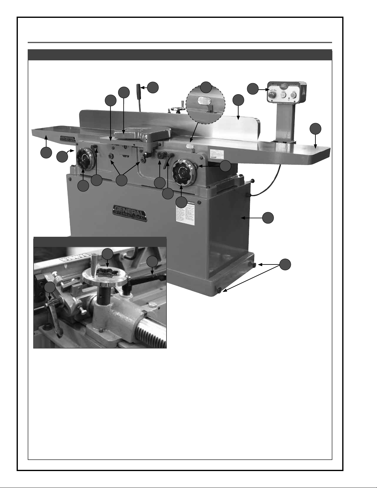
IDENTIFICATION OF MAIN PARTS AND COMPONENTS
FRONT VIEW
D
E
C
F
H
G
I
A
P
P
N
B
O
N
M
L
J
REAR VIEW
Q
R
K
P
A. OUTFEED TABLE
B. OUTFEED TABLE ADJUSTMENT HANDWHEEL
C. RABBETING ARM
D. CUTTER HEAD GUARD
E. FENCE TILT LEVER
F. DEPTH OF CUT INDICATOR
G. FENCE
H. MAGNETIC SWITCH
I. INFEED TABLE
J. BASE WITH MOTOR
K. WHEEL LOCK KNOBS
L. INFEED TABLE ADJUSTMENT HANDWHEEL
M. TABLE LOCKING LEVER
N. TABLE DEPTH ADJUSTMENT LOCK PIN
O. ECCENTRIC ADJUSTERS
P. FENCE LOCKING LEVER
Q. FENCE ADJUSTMENT HANDWEEL
R. FENCE TILT LOCKING LEVER
8
Page 9
BASIC FUNCTIONS
This 12” jointer is designed for face and edge jointing in solid wood only. The unit is not designed nor should it be
used to surface or prepare plywood, wood panelling, particleboard, MDF, nor any other wood based by-products
nor any non-wood based materials.
The 80-325 features a precision four point parallelogram table adjustment system that allows for easy parallel
alignment of infeed and outfeed table to the cutter head and to each other. This jointer is offered with two different
cutter head options:
• Model 80-325 – 12” jointer with standard 3-knife cutter head.
• Model 80-325HC – 12” jointer with Magnum helical cutter head with 32 2- sided reversible inserts.
UNPACKING
Carefully unpack and remove the unit and its components from its shipping container and check for missing or
damaged items as per the list of contents below.
NOTE: Please report any damaged or missing items to your General® International distributor immediately.
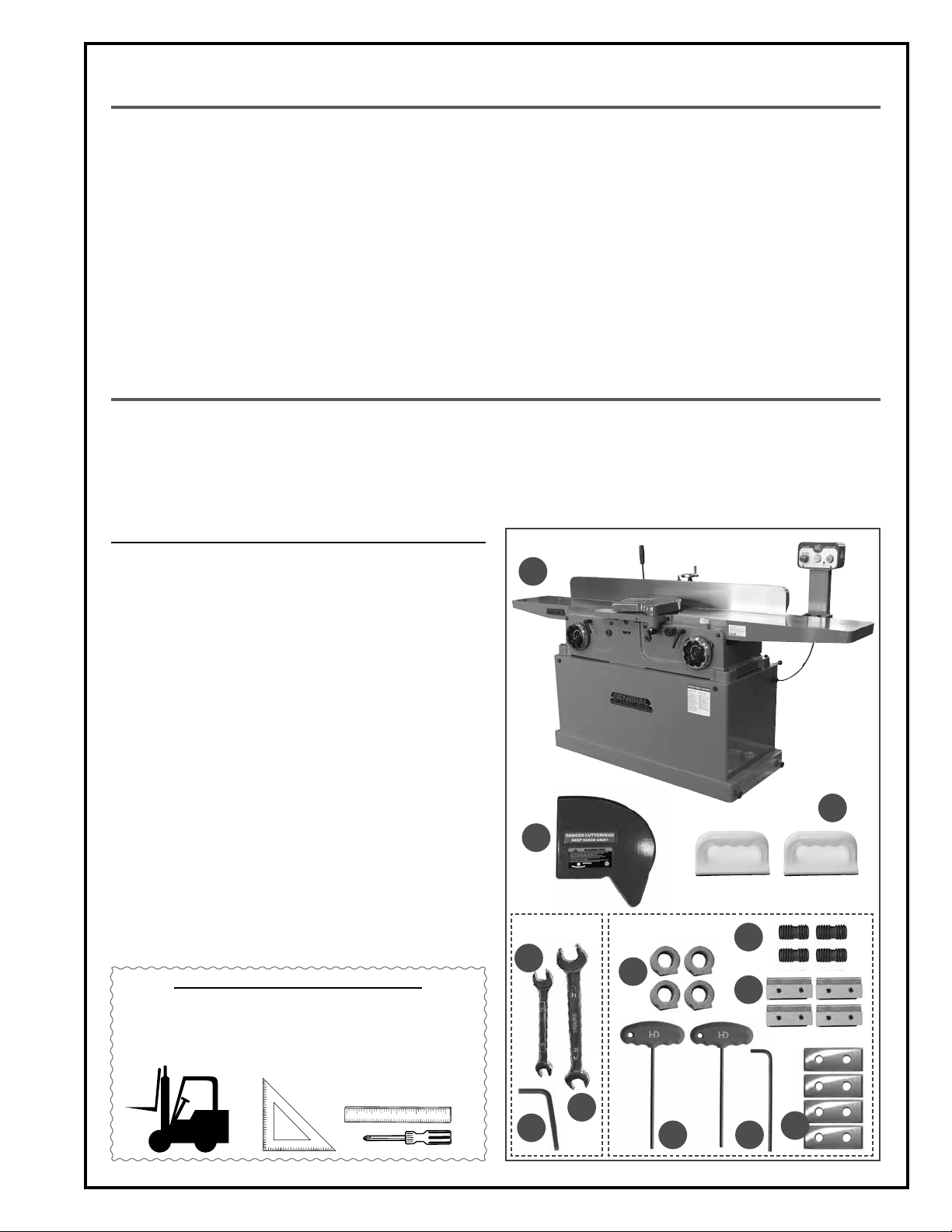
LIST OF CONTENTS QTY
A.
JOINTER* ................................................................................. 1
B. CUTTER HEAD GUARD ............................................................. 1
C. PUSH BLOCK ............................................................................ 2
D. 11-13 MM OPEN END WRENCH .............................................. 1
E. 17-19 MM OPEN END WRENCH .............................................. 1
F. 4 MM ALLEN KEY ..................................................................... 1
* Important! To avoid disaligning the tables, never lift or
move the jointer by it’s tables when lifting. Always use
the lifting bars to lift or move the jointer.
A
HELICAL CUTTER HEAD TOOLS/REPLACEMENT PARTS
(FOR MODEL 80-325HC M1 ONLY):
G. 5 MM T ALLEN KEY ................................................................... 2
H. 5 MM ALLEN KEY ..................................................................... 1
I. NUT ........................................................................................... 4
J. SCREW...................................................................................... 4
K. KNIFE-HOLDER / CHIP-BREAKER ............................................. 4
L. CARBIDE INSERT (STARDARD) ................................................. 4
ADDITIONAL REQUIREMENTS FOR SET UP
• Forklift or hoist for lifting
• Straight edge
• 45º & 90º combination
square
• Phillips Screwdriver
B
80-325 M1
ONLY
D
F
C
80-325HC M1
ONLY
J
I
K
E
G
H
L
9
Page 10
CLEAN UP
The protective coating on the jointer tables prevents rust from forming during shipping and storage. Remove it by
rubbing with a rag dipped in kerosene, mineral spirits or paint thinner. (Dispose of potentially flammable solventsoaked rags according to manufacturer’s safety recommendations.)
A putty knife, held flat to avoid scratching the surface, may also be used to scrape off the coating followed by
clean-up with solvent. Avoid rubbing the saw’s painted surfaces, as many solvent-based products will remove
paint.
To prevent rust, apply a light coating of paste wax or use regular applications of any after-market surface protectant or rust inhibitor.a
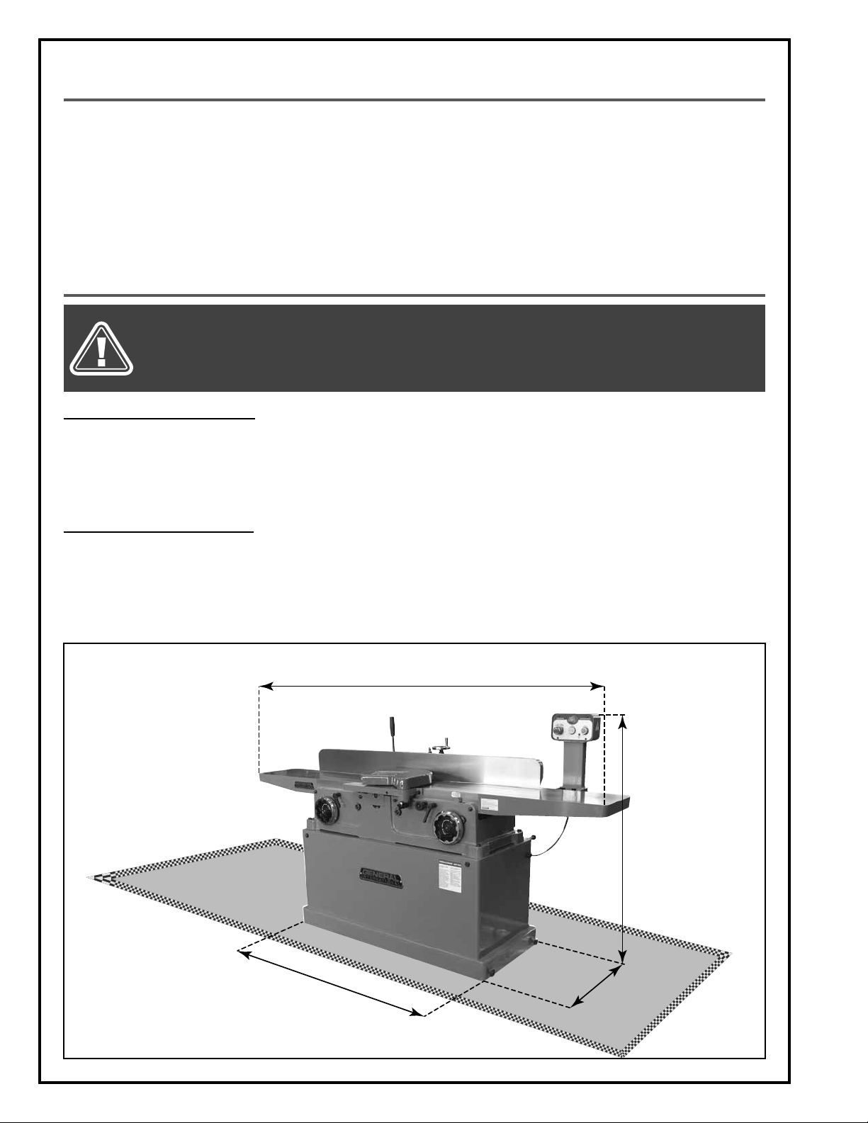
PLACEMENT WITHIN THE SHOP / SAFETY ZONE
THIS MODEL 80-325 12” JOINTER IS HEAVY. DO NOT OVER-EXERT. A HOIST OR FORKLIFT WITH STRAPS SHOULD BE USED
TO LIFT THIS MACHINE.
TO LIMIT THE RISK OF SERIOUS INJURY OR DAMAGE TO THE MACHINE, ANY EQUIPMENT USED TO LIFT THIS MACHINE
SHOULD HAVE A RATED CAPACITY IN EXCESS OF 979 LBS (445 KG).
PLACEMENT WITHIN THE SHOP
This machine should be installed and operated only on a solid, flat and stable floor that is able to support the
weight of the jointer and the operator.
Plan for placement within your shop that will allow the operator to work unencumbered and unobstructed by foot
traffic (either passing shop visitors or other shop workers) or other tools or machinery.
ESTABLISHING A SAFETY ZONE
For shops with frequent visitors or multiple operators, it is advisable to establish a safety zone around shop machinery. A clearly defined “no-go” zone on the floor around each machine can help avoid accidents that could cause
injury to either the operator or the shop visitor.
It is advisable to take a few moments to either paint (using non-slip paint) or using tape, define on the floor the limits or perimeter of each machines safety zone. Take steps to ensure that all operators and shop visitors are aware
that these areas are off limits whenever a machine is running for everyone but the individual operating the unit.
87 3/4"
47 5/8"
1
"
2
/
1
50
Base dimensions:
21 1/2” x 50 1/2” (546 x 1283 mm)
Overall dimensions (L x W x H):
87 3/4” x 41” x 47 5/8” (2230 x 1042 x 1210 mm)
10
1
/
2"
2
Page 11

ASSEMBLY INSTRUCTIONS
For your convenience this jointer is shipped from the factory partially assembled and requires only minimal assembly and set up before being put into service.
SERIOUS PERSONAL INJURY COULD OCCUR IF YOU CONNECT THE MACHINE TO THE POWER SOURCE BEFORE YOU
HAVE COMPLETED THE INSTALLATION AND ASSEMBLY STEPS. DO NOT CONNECT THE MACHINE TO THE POWER SOURCE
UNTIL INSTRUCTED TO DO SO.
REPOSITION THE SWITCH POST
To limit the potential for damage in transport, this jointer is shipped from the factory with the switch post in the horizontal position A. The switch post must be repositioned in the vertical position B.
A
B
C
C
1. Remove the 3 cap screws and flat washers C that
secure the post to the jointer bed.
2. Reposition the switch post to the vertical position
and secure in place with the 3 cap screws and flat
washers.
INSTALL THE CUTTER HEAD GUARD
The cutter head guard is designed to automatically snap back against the fence and cover the knives once the
workpiece has cleared the guard. To install the guard, proceed as follows:
A
B
1. To give yourself unimpeded access to the cutter
head, loosen the fence locking handle B, then use
handwheel A to move the fence backwards, out of
the way.
D
C
C
2. Loosen locking handle C on the rabbeting arm at
the front of the jointer and fit the shaft of the cutter
head guard as far as it will go down into the mounting hole D.
3. Adjust the positioning of the guard so that it com pletely covers the cutter head.
4. Tighten locking handle C to secure the cutter head
guard in position.
11
Page 12

ADJUSTING AND SETTING THE OUTFEED TABLE HEIGHT
The outfeed table should be set level with the highest point of the knives A. The height of the outfeed table should
be verified and adjusted prior to first use. It should also be verified and re-adjusted periodically to compensate for
knife wear and also upon knife replacement.
ALWAYS DISCONNECT THE MACHINE FROM THE POWER SOURCE BEFORE MAKING ANY ADJUSTMENTS. FAILURE TO
HEED THIS WARNING CAN LEAD TO SERIOUS PERSONAL INJURY.
OUTFEED TABLE
(LEFT)
INFEED TABLE
(RIGHT)
A
1. Make sure that the the machine is disconnected
from the power source.
2. To give yourself unimpeded access to the cutter
head and upper pulley, remove the cutter head
guard and move the fence backwards, out of the
wa y.
3. Set a straight edge onto the outfeed table so that it
sits over the cutter head but does not completely
cross the gap between the tables and touch the in feed table A.
4. Turn the cutter head by hand until any one of the
knives is at it’s highest point.
D
B
5. Loosen outfeed (left) table adjustment handwheel
lock knob B.
6. Flip handle C down then use left handwheel D to
adjust the outfeed table height so that the knife
barely touches the straight edge.
7. Flip handle C up to allow you to keep the hand-
wheel from interfering while jointing.
8. Re-tighten lock knob B to secure the outfeed table
in position.
C
ADJUSTING THE DEPTH OF CUT
THE MAXIMUM DEPTH OF CUT FOR ONE PASS IS 1/8”. NEVER ATTEMPT TO REMOVE MORE MATERIAL THAN 1/8” IN
ANY SINGLE PASS.
ALWAYS DISCONNECT THE MACHINE FROM THE POWER SOURCE BEFORE MAKING ANY ADJUSTMENTS. FAILURE TO
HEED THIS WARNING CAN LEAD TO SERIOUS PERSONAL INJURY.
The depth of cut A is set by raising or lowering the infeed table. Refer to the recommended depth of cut settings in section “Basic Jointing Operations Instructions”,
on page 17.
12
WORKPIECE
DEPTH
OF CUT
Page 13

1. Loosen the infeed (right) table locking lever C.
2. Flip the handle down then use the handwheel B to
adjust the infeed table height to the desired depth
of cut.
Note: Refer to the graduated depth scale D.
3. Flip handle B up to allow you to keep the hand wheel from interfering while jointing.
4. Re-tighten locking lever C to secure the infeed ta-
ble in position.
TABLE ALIGNMENT
The outfeed table and infeed table have been factory set parallel to the cutter head and to each other. However with use and vibration over time, it may eventually become necessary to re-align the tables. Refer to the
instructions in section “Maintenance”, on pages 18 to 22 of this manual.
CHECKING / ADJUSTING THE ZERO POINT STOP BOLT
The zero point stop bolt has been factory set to prevent the infeed table from being raised higher than the
cutter head.
However with use and vibration over time, it may eventually become necessary to re-adjust the zero point stop
bolt and depth of cut indicator. Refer to the instructions in section “Maintenance”, on page 22 of this manual.
C
D
B
ADJUSTING THE FENCE AND SETTING THE FENCE STOPS
The fence stops allow you to position the fence at specific pre-set angles in relation to the tables without having
to measure each time you return to that angle. Due to wear and vibration, fence stops can over time become
misaligned and should be checked periodically and re-set if necessary.
EF
A
B
C
To move the fence front to back:
1. Loosen locking lever A, then position the fence over
the cutter head as needed using handwheel B.
2. Re-tighten locking lever A.
To tilt the fence:
1. Loosen locking lever C, and set the fence 45° inward or 45° outward.
2. Re-tighten locking lever C.
90°
D
To set the 90° fence stop:
Using a 90° machinists square, set the fence to 90° D.
1.
2. Flip the 90° stop into position E.
3. Loosen the jam nut F on the 90° fence stop bolt.
4. Adjust the 90° fence stop bolt G until it makes con tact with the 90° stop E.
5. Re-tighten the jam nut F.
G
13
Page 14

ADJUSTING THE FENCE AND SETTING THE FENCE STOPS (CONTINUED)
H K
J
I
To set the 45° outward fence stop:
1. Using a combination or machinists square, set the
fence to 45° outward H.
2. Loosen the jam nut I on the 45° outward fence stop
bolt.
3. Adjust the 45° outward fence stop bolt J until it
makes contact with the back of the fence.
4. Re-tighten the jam nut I.
L
M
N
To set the 45° inward fence stop:
1. Using a 45° combination or machinists square, set
the fence to 45° inward K.
2. Flip the 90° stop into position L.
3. Loosen the jam nut M.
4. Adjust the 45° inward fence stop bolt N until it makes
contact with the back of the stop L.
5. Re-tighten the jam nut M.
OPERATING INSTRUCTIONS
CONNECTING TO A DUST COLLECTOR
A dust port with a 6” opening A is provided to accommodate connection to a dust collector B (not included).
Be sure to use appropriate sized hose and fittings (not
included) and check that all connections are sealed
tightly to help minimize airborne dust.
If you do not already own a dust collection system
consider contacting your General® International distributor for information on our complete line of dust collection systems and accessories or visit our Web Site at
www.general.ca.
BASIC PRINCIPLES OF JOINTING
This jointer is designed to remove material from one face
of a board in order to make it (or a series of boards) perfectly flat A.
This perfectly flat face is then placed against the fence,
set at 90º to the tables, to obtain a perfectly perpendicular 90º flat edge B.
A B
A
B
14
Page 15

SELECTING BOARDS SUITABLE FOR JOINTING
This jointer is not intended (and should not be used) to joint any material other than solid wood.
ALWAYS JOINT IN THE GENERAL DIRECTION OF THE GRAIN. JOINTING AGAINST THE GRAIN OR JOINTING END GRAIN
IS DANGEROUS AND MAY CAUSE THE WORKPIECE TO SHATTER.
1. Jointing safety begins with the stock used with the
machine. Inspect the work piece carefully before
jointing it. Never joint a board that has loose knots,
staples, nails or other embedded foreign objects. If
you have the slightest doubt about the structural
integrity or stability of a board:
Do Not Joint It
.
2. Only boards with the grain running more or less
length-wise are suitable for jointing A.
DETERMINE THE CONCAVE FACE AND EDGE OF YOUR BOARD
Place your board on a flat surface to identify its concave face B and edge C. The boards must be jointed
with the concave face and edge against the jointer ta
ble.
A
GRAIN DIRECTION
GRAIN DIRECTION
-
B
C
ADJUST FENCE FRONT TO BACK POSITION
To limit your exposure to the knives in the cutter head,
never take more knive length than is required to complete the cut. Set the position of the fence so that the
length of blade remaining exposed is roughly 1/4” longer than the width of the board to be jointed.
1/4”
1/4”
FACE JOINTING EDGE JOINTING
CHECKLIST BEFORE STARTING
VERIFY ALL CHECK POINTS BEFORE STARTING. FAILURE TO COMPLY CAN RESULT IN SERIOUS INJURIES.
• Make sure you and any assistants are wearing safe appropriate workshop attire. Roll up long sleeves, secure
long hair and remove any jewelry: watches, rings, bracelets or anything that could become caught in the
moving parts, potentially causing serious injury.
• Make sure the board has been inspected and is suitable for jointing as explained in the previous section
“Selecting boards suitable for jointing”.
Verify that the cutter head guard is functioning properly (snaps back against the fence and covers the knives).
•
• Make sure that the fence is properly set and locked in place.
• Make sure to have on safety glasses as well as hearing and respiratory protection at all times when using the
jointer.
15
Page 16

CONNECTING TO A POWER SOURCE
TO REDUCE THE RISK OF SHOCK OR FIRE DO NOT OPERATE THE UNIT WITH A DAMAGED POWER CORD OR PLUG. REPLACE
DAMAGED CORD OR PLUG IMMEDIATELY.
TO AVOID UNINTENTIONAL START-UP, MAKE SURE THAT THE POWER SWITCH IS IN THE OFF POSITION BEFORE CONNECTING TO
A POWER SOURCE.
Once the assembly and adjustment steps have been
completed, uncoil the power cord and plug it into an
appropriate outlet. The Power-on indicator light A will illuminate.
SWITCH OFF
When jointing operations have been completed unplug
the jointer from the power source.
Refer back to the section
entitled “ELECTRICAL REQUIREMENTS” and make sure all
A
requirements and grounding
instructions are followed.
MAGNETIC SAFETY SWITCH
This model 80-325 jointer is equiped with a magnetic
safety switch mounted inside the cabinet that is connected to a control box above the infeed table for
quick, easy access. It is designed to protect the unit
and the user from power surges, power outages and
unintentional start-up.
To start the jointer: Push on the green “START” button B.
Wait for the cutter head to reach full speed before jointing.
To stop the jointer: Push on the RED “STOP” button C and
wait for the cutter head to come to a complete stop.
Once the RED “STOP” button has been pressed, the machine
can only be started by turning the inner part of the button D to the right to release the stop button.
C B
D
BASIC JOINTING OPERATIONS
FAILURE TO USE PUSH BLOCKS WHEN FACE JOINTING MAY RESULT IN SERIOUS PERSONAL INJURY. ALWAYS USE PUSH BLOCKS
TO HELP KEEP YOUR HANDS AT A SAFE DISTANCE FROM THE KNIVES WHEN FACE JOINTING.
FACE JOINTING
1. Inspect the stock before starting & remove any for-
eign objects or debris.
2. Set the depth of cut as required (1/32” is recom mended for face planing - Less for hard wood or
wider stock.)
3. Set & lock the fence at 90°.
4. If your workpiece is cupped, place the cupped
side face down on the infeed (right) table.
5. Set the position of the fence so that the length of
blade remaining exposed is roughly 1/4” longer
than the width of the board to be jointed.
6. Turn on the machine & using push blocks press the
stock against the table and tight to the fence, feed ing the stock over the cutter head.
7. Inspect the board & repeat the steps if needed until the surface is flat.
16
Page 17

EDGE JOINTING
1. Inspect the stock before starting & remove any
foreign objects or debris.
2. Set the depth of cut as required (1/16” - 1/8” is re-
commended for edge jointing - Less for hard wood
or wider stock.)
3. Set & lock the fence at 90°.
4. If your workpiece is cupped, place the cupped
side face down on the infeed (right) table.
5. Set the position of the fence so that the length of
blade remaining exposed is roughly 1/4” longer
than the width of the board to be jointed.
6. Turn on the machine, press the stock against the
table and tight to the fence, feeding the stock over
the cutter head.
7. Inspect the board & repeat the steps if needed until the surface is flat.
RABBETING
REMOVE THE BLADE GUARD FOR RABBETING ONLY. IMMEDIATELY REPLACE THE BLADE GUARD WHEN FINISHED. DO NOT PERFORM ANY OTHER JOINTING OPERATION WITH THE BLADE GUARD REMOVED. FAILURE TO HEED THIS WARNING CAN LEAD TO
SERIOUS PERSONAL INJURY.
1. Remove the blade guard & move the fence forward leaving only the width of the desired rabbet on the tables
uncovered by the fence & lock the fence in position.
2. Inspect the stock before starting & remove any foreign objects or debris.
3. Set the depth of cut as required (1/16” - 1/8” is recommended for rabbeting - Less for hard wood or wider
stock.)
4. Turn on the machine & using push blocks press the stock against the tables rabbeting arm and tight to the
fence, feeding the stock over the cutter head.
5. Repeat the steps until the rabbet is cut to the desired depth.
MAINTENANCE
MAKE SURE THE JOINTER HAS BEEN TURNED OFF AND UNPLUGGED FROM THE POWER SOURCE BEFORE PERFORMING
ANY MAINTENANCE. FAILURE TO HEED THIS WARNING CAN LEAD TO SERIOUS PERSONAL INJURY.
INSPECTING/REPLACING CUTTER HEAD KNIVES
Model 80-325 only:
There are 3 knives installed in the cutter head at the
factory. With usage and normal wear over time, it will
eventually become necessary to replace the knives. To
maintain even knife wear always replace all 3 knives at
the same time.
When needed, replacement knives (sold in sets of 3)
A can be ordered through your local General International distributor under part #80-012 (High Speed Steel)
or #80-013 (Carbide).
Model 80-325HC only:
There are 32 reversible carbide inserts (knives) installed
in the helical cutter head at the factory. With usage and
normal wear over time, it will eventually become necessary to reverse and/or replace the inserts. To maintain even insert wear always reverse or replace all 32
inserts each time knife replacement is required.
When needed, replacement inserts B can be ordered
through your local General International distributor under part #30-443.
A
MODEL 80-325 ONLY
B
MODEL 80-325HC ONLY
17
Page 18

INSPECTING/REPLACING CUTTER HEAD KNIVES (CONTINUED)
Observing jointed workpieces as they come off of the
machine and looking for signs of knife damage or
C D
wear is the best method to help you to determine when
knives are due to be changed.
1. A raised ridgeline in the workpiece that runs a
straight line from beginning to end of the board C.
This is generally an indication that one or more
knives has been nicked or damaged D by a for eign object such as a nail, staple or other hard ob ject hidden or embedded in the workpiece.
2. A slight washboard or chatter effect E which can
be an indication of uneven knife wear causing
one knife to cut slightly deeper than the others.
E
3. Rough, irregular, torn or fuzzy grain on a freshly
jointed surface may be a sign of worn or dull
blades causing the wood to tear out. Sharp blades cut crisply and leave a relatively smooth finish.
Note: Fuzzy grain can also be a sign of high moisture content in the workpiece. If knives have recently been changed or
if you suspect that moisture content and not dull knives is the cause, set the workpiece aside and test by jointing other
boards with known or acceptable moisture content. If the jointed results using a different workpiece are smooth, then
moisture content in your wood is the problem - no adjustments can be made to the machine for this. Set the “wet” stock
aside and simply work with drier wood.
KNIFE SETTING / REPLACEMENT - 80-325 ONLY
Properly setting all three knives is essential to achieving accurate work results. Properly set knives will last longer
and also keep their edge (sharpness) longer by equally sharing the cutting workload. You may use the supplied
knife setting gauge to help you set the knives to the correct height whenever re-setting or changing knives.
Note: If you prefer you may also find other “aftermarket” gauges, jigs or knife setting tools that are to your liking – ask your
local tool distributor for information on any such tools that may be available in your market.
KNIFE EDGES ARE VERY SHARP. USE CARE WHEN HANDLING INSERTS.
MAKE SURE THE JOINTER HAS BEEN TURNED OFF AND UNPLUGGED FROM THE POWER SOURCE BEFORE PERFORMING
ANY MAINTENANCE. FAILURE TO HEED THIS WARNING CAN LEAD TO SERIOUS PERSONAL INJURY.
The cutter head on this unit is supplied with both adjustment springs and jack screws A providing you with two
options for setting the knives. We suggest you try each
method at least once or twice and decide for yourself
which method works best and fastest for you.
1. Turn off and disconnect the machine from the po wer source.
2. To give yourself unimpeded access to the cutter
head and knives, remove the blade guard and
lower the tables as far as they go.
3. Remove the fence to have access to the upper pul ley and turn it by hand to rotate the cutter head to
access one of the knives.
4. Loosen (but don’t remove) all the gib bolts B – start
in the center and alternate sides (If replacing an
old or damaged knife, loosen the bolts until the
knife can be removed and install a new sharpened
knife). Then position the gauge over the selected
knife D.
To use the adjustment springs to set the knife
height:
Push the knife down with the gauge so that
the edge of the knife is touching the center refe rence pads on the gauge E. Hold the gauge down
and tighten the bolts B to secure the knife in place.
Repeat for the 2 other knives.
JACK SCREW
A
KNIFE
GIB
GIB BOLT
SPRING
C
B
18
Page 19

KNIFE SETTING / REPLACEMENT - 80-325 ONLY (CONTINUED)
To use the Jack Screws to set the knife height:
Use an Allen wrench to turn the screws C to raise or
D
lower the knife as needed until the ideal position
- both sets of feet of the gauge sitting flush on the
cutter head and the knife barely touching the center reference pads on the gauge E – has been
achieved. Repeat for the 2 other knives.
5. Re-check the height setting on all the knives and
reset if necessary.
6. Reset the tables and replace the fence and blade
guard.
IMPORTANT! After changing or resetting the knives, the outf
eed (left) table height must be re-adjusted to match the new
height of the knives. Follow the instructions in section “Adjusting and Setting the outfeed Table Height” .
E
HELICAL CUTTER HEAD INSERT REVERSAL / REPLACEMENT - 80-325HC ONLY
INSERT EDGES ARE VERY SHARP. USE CARE WHEN HANDLING INSERTS.
MAKE SURE THE JOINTER HAS BEEN TURNED OFF AND UNPLUGGED FROM THE POWER SOURCE BEFORE PERFORMING
ANY MAINTENANCE. FAILURE TO HEED THIS WARNING CAN LEAD TO SERIOUS PERSONAL INJURY.
B
C
A
1. Using the one of the supplied long Allen keys, loo-
sen but do not remove the nut and screw A and re move the knife-holder/chip breaker B and insert C.
F
E
Important! To prevent knife height
discrepencies, the knife holders /
chip breakers and inserts must be
clean and free of debris.
G
D
2. Thoroughly clean the housing D before re-installing
a knife-holder/chip breaker and insert.
H
3. Thoroughly clean the knife-holders/chip breakers E
and inserts F using a lacquer thinner and small
brush.
4. Reverse or replace the insert and re-install it along
with the knife-holder/chip breaker into the slot, then
partially Re-tighten the nut and screw G.
5. Center the knife-holder/chip breaker with the flat
edge of the nut H and fully tighten the nut and
screw.
6. Repeat with all other inserts.
19
Page 20

HELICAL CUTTER HEAD INSERT REVERSAL / REPLACEMENT - 80-325HC ONLY (CONTINUED)
Important! The nut and screw that secures the knife-holder/chip breakers and inserts in the cutter head does not have
to be removed for blade reversal/replacement, only loosened. If the nuts and screws have to be replaced or if they
have been removed instead of loosened, follow the instructions below to make sure that the knife-holder/chip breakers are all secured at the same height into the cutter head.
1. Place the screw in the threaded hole but don’t start tightening
it yet.
3. Holding the nut with your fingers, tighten the screw. This will tight en both the screw and nut simultaneously.
2. Place the nut on top of the screw but don’t start tightening
the screw yet.
Do not thread the nut onto the
screw before tightening the screw
into the threaded hole in the
cutter head.
PARALLEL (CO-PLANAR) ALIGNMENT OF THE INFEED AND OUTFEED TABLES
In order to obtain precision jointing results it is essential that the infeed and outfeed tables are aligned parallel
(co-planar) to each other at all times. If the end of one or both tables is tilted higher or sags lower A, or if either
table tilts inward or outward out of parallel with the other B, this will result in jointed workpieces that are not flat or
that cannot be face and then edge jointed to achieve a perfect 90° angle.
To facilitate precision table alignment this 80-325 jointer features a parallelogram style 4-point adjustment system
on each table. In order to achieve perfect alignment, the tables should be verified at the front (closest to the operator), back (closest to the fence) and across both diagonals (corner to corner) using a precision straight edge,
preferably one that is as long as the two tables.
A B
C
1. Disconnect the machine from the power source.
2. Remove the 4 plastic plugs C from around each
table.
20
C
D
3
. Using the supplied 4 mm Allen key, loosen the 4 lock-
ing screws D located under the plugs C, 1 1/2 or
2 turns each.
D
Page 21

PARALLEL (CO-PLANAR) ALIGNMENT OF THE INFEED AND OUTFEED TABLES (CONTINUED)
G H
OUTFEED TABLE
(LEFT)
INFEED TABLE
(RIGHT)
F
Note: Remove the cutter head guard and move the fence
backwards, out of the way.
4. Raise the outfeed table higher than the cutter head
then set the infeed table to the same height as the
outfeed table F.
J
K
J
I
5. Set a precision straight edge G onto the outfeed
and infeed tables (near the rear edge H of the
tables) and check for a gap between the straight edge and the tables I
L
N
M
N
6.
Use the supplied 17-19 mm open wrench to adjust the
two eccentric adjusters J and K located on the rear
edge of either/both tables to eliminate the gap bet ween the table(s) and the straight edge.
J
K
O
M
N
9. Set the straight edge onto the tables diagonally
(corner to corner) as shown, O, and check for a
gap between the straight edge and the tables.
10. If needed, adjust the two eccentric adjusters J and
K located on the rear edge of the outfeed table
and/or M and N located on the front edge of the
infeed table to eliminate the gap between the
table(s) and the straight edge.
7. Set the straight edge near the front edge L of the tables.
8. Adjust the two eccentric adjusters M and N located on
the front edge of either/both tables to eliminate the
gap between the table(s) and the straight edge.
P
N
K
J
M
11. Set the straight edge onto the tables in the opposite
diagonal position (as shown), P, and check for a gap
between the straight edge and the tables.
12. If needed, adjust the two eccentric adjusters N and M
located on the front edge of the outfeed table and/
or K and J located on the rear edge of infeed table
to eliminate the gap between the table(s) and the
straight edge.
13. Repeat the previous steps as needed until align ment has been achieved.
21
Page 22

PARALLEL (CO-PLANAR) ALIGNMENT OF THE INFEED AND OUTFEED TABLES (CONTINUED)
14. With the outfeed and infeed tables coplanar, tighten
the 4 locking screws D on both tables.
15. Re-install the 4 plastic plugs C on both tables.
C
D
PERIODIC MAINTENANCE
To prolong the service life of your jointer and to maintain optimum performance the following basic maintenance
procedures should be practiced and become part of your shop routine.
• Inspect/test the ON/OFF switch before each use. Do not operate the jointer with a damaged switch; re-
place a damaged switch immediately.
• Keep the machine as well as the infeed outfeed tables clean and free of saw dust, woodchips, pitch or
glue. Vacuum or brush off any loose debris and wipe down the machine and the tables occasionally with a
damp rag.
• An occasional light coating of paste wax can help protect the tables’ surface and reduce workpiece fric-
tion. Ask your local distributor for suggestions on aftermarket surface cleaners, protectant and dry lubricants
based on what is readily available in your area.
• Avoid using silicon based products that may affect or react with wood finishing products such as oil, solvent
or water-based stains, varnishes and lacquers.
• Periodically inspect the power cord and plug for damage. To minimize the risk of electric shock or fire, never
operate the jointer with a damaged power cord or plug. Replace a damaged power cord or plug at the first
visible signs of damage.
• All bearings are sealed and permanently lubricated and no further lubrication is required. The fence as-
sembly and table ways also should not be lubricated. If you should encounter a “sticking” problem, simply
disassemble and clear away any obstructions from the ways.
• Regularly inspect jointed workpieces for signs of knife damage or wear and replace damaged or worn
knives immediately.
• Inspect the belt regularly – To avoid potentially costly downtime, consider keeping a spare replacement belt
on hand for use if needed. Belts that show visible signs of wear such as cracks or fraying at the edges should
be replaced immediately.
ADJUSTING THE INFEED TABLE ZERO POINT AND DOWN STOPS
With use and vibration over time, it may eventually become necessary to re-adjust the zero point and down stops.
Proceed as follows if needed:
Note: For more clarity, the cutter head guard has been removed.
A
1. Place a straight edge on infeed table and the cut-
ter head. Set the table at the zero point using the
handwheel and the depth of cut scale A.
22
2. Hand turn the cutter head until one of the knives is
at its highest point, then refine table position with
the handwheel so that the knife almost touches the
straight edge.
Page 23

ADJUSTING THE INFEED TABLE ZERO POINT AND DOWN STOPS (CONTINUED)
3. Once the infeed is set to zero, lock the table in posi-
tion by turning its lock lever clockwise.
5. Using a 5 mm Allen key, remove the 3 cap screws
at the bottom of the control box, and then put the
control box aside.
4. Using a 17 mm wrench, remove the 4 bolts in each
corner of the machine.
6. Loosen the rear panel using a 3 mm Allen key.
B
7. Loosen the nuts B to loosen the belt. 8. Remove the belt from motor pulley.
23
Page 24

ADJUSTING THE INFEED TABLE ZERO POINT AND DOWN STOPS (CONTINUED)
9. Remove the guard upper pulley lock knob, the re-
move the guard.
11. Install appropriate lifting straps around the lifting
bars, then lift the machine until you can access underneath the machine.
10. Remove the belt from the upper pulley.
C
12. Under the infeed table, loosen the zero stop C lo-
cated to the left on the lead screw using a 5 mm
Allen key.
D
13. Hand slide the zero stop against the block D, then
Re-tighten zero stop.
24
E
14. Set the machine on its support, lower the table at
3/4” using the depth of cut scale. Then perform
the steps 9 to 11 with the left down stop of the lead
screw E.
15. Re-tighten the machine on its support, re-install the
belt, the pulley guard, the rear panel, the cutter
head guard and the control box.
Page 25

RECOMMENDED OPTIONAL ACCESSORIES
Here is a sampling of optional accessories available from your local General International dealer to help you
increase convenience, productivity, accuracy and safety when using your machine.
For more information about our products, please visit our website at www.general.ca
For use with #80-012 and
#80-013 knives only.
Item #80-012
12” HI-SPEED STEEL
BLADE (SET OF 3)
Item #30-433
REPLACEMENT INSERTS
For MAGNUM helical cutter head - 80325H- 4 rows,
total: 32 inserts
Item #30-025
MAGNETIC, MICROADJUSTABLE PLANER
AND JOINTER KNIFE
ALIGNMENT GAUGE
Keeps knives in perfect
alignment, accurat to +/-
0.001” (+/- 0.025 mm).
Suitable for all planer and
jointer knives from 6” – 26” in
length.
The easiest way to set planer
and jointer knives.
For use with #80-012 and
#80-013 knives only.
Item #80-013
12” CARBIDE BLADE
(SET OF 3)
DUST COLLECTORS
Dust collectors contribute to a cleaner more
healthful workshop environment.
We offer a wide selection of top quality dust
collectors to suit all your
shop needs.
Item #30-050
DIAL-GAUGE MICROMETER
FOR PLANER AND JOINTER
KNIFE ALIGNMENT
Precision built, easy to adjust, mounted on enamel
finished alloy steel.
Designed to rest squarely
on the cutter head for fast
accurate knife alignment.
Dial is easy to read and
just.
ad-
For use with #80-012 and
#80-013 knives only.
Item #30-075
JOINTER KNIFE
ALIGNMENT JIG
8 7/8” Alloy steel bars with
3 magnetic points for precise alignment of jointer
knives.
Assures perfect finished
cuts to an accuracy of
± 0.001” (±0.025 mm).
Can be used on most
jointer models.
Maximum load
capacity of 400 lbs.
Item #50-167S
FLEXIBLE EXTENDABLE
ROLLER STAND
Adjustable height from
24 1/4” to 37”.
9 nickel-plated 2-way rollers
2 1/4” x 20”.
51 1/2” maximum expanded length.
21 1/4” compacted length.
4” wheels with locking foot
levers.
25
Page 26

HEAD
71
14
72
28
73
31
75
74
28
72
73
14
71
31
76
61
58
66
63
42
167
40
.3
.2
.1
47
51
52
51
14
46
52
53
55
54
14
46
62
62
62
69
57
58
57
56
60
63
48
100
61
107
65
107
65
107
79
78
77
.4
.3
.6
.5
.1
.2
B
C
93
629691
15
92
93
62
91
92
96
96
112
111
15
92
92
15
98
100
101
102
104
98
103
100
62
96
103
98
99
104
98
99
102
101
98
95
94
98
95
94
98
95
119
120
121
122
59
120
123
.2
.1
124
125
115
114
113
15
115
114
113
115
116
96
119
120
121
59
115
116
120
123
125
28
124
133
132
130
129
98
49
128
127
96
117
115
114
113
108
109
110
D
28
100
100
99
164
164
166
165
125
84
121
121
118
41
118
41
118
41
118
41
43
44
50
88
44
43
43
44
50
88
44
43
166
165
125
84
122
105
105
97
180
99
97
180
77
.2 .5
.4
.6
.3
.8
.7
.9
.1
158
83
84
80
87
86
62
60
63
57
56
57
61
58
63
60
58
61
66
63
63
62
79
78
77
45
42
40
100
65
107
65
107
107
26
Page 27

BASE
77
113
158
14
150
.03
14
113
126
.06
.04
.07
.08
.03
.01
.05
.02
.02
.2
.3
.4
139
62
140
126
13
155
156
157
.1
D
158
E
77
149
154
159
137
126
160
161
106
162
163
160
160
163
161
162
126
141
131
139
90
2
2
90
2
126
13
90
138
2
90
138
142
153
152
143
142
62
160
159
137
111
126
98
135
111
136
98
111
126
137
126
137
98
160
163
162
159
160
27
Page 28

FENCE
8
10
9
70
14
46
67
68
7
8
5
4
3
6
11
6
2
1
5
12
13
14
15
2221
2019
13
14
16
23
15
24
26
25
64
67
68
18
17
27
29
31
28
28
27
28
28
2
24
14
134
46
24
30
8
283124
34
145
32
33
146
144
147
81
28
35
.2.1.3
32
33
373638
39
Page 29

PARTS LIST
80-325 / 80-325HC
IMPORTANT: When ordering replacement parts, always give the model number, serial number of the
machine and part number. Also a brief description of each item and quantity desired.
PART # DESCRIPTION SPECIFICATION QTY
80325-01 LOCKING LEVER 1
80325-02 FLAT WASHER 13.5 X 32 X 3.0T 6
80325-03 CAP SCREW M10 X 1.5P X 65 1
80325-04 NUT M10 X 1.5P (17B X 8H) 1
80325-05 CAP SCREW M4 X 0.7P X 12 2
80325-06 KEY 2
80325-07 HANDWHEEL 1
80325-08 SET SCREW M6 X 1.0P X 10 4
80325-09 SPACER 1
80325-10 COLUMN MOUNT 1
80325-11 GEAR SHAFT 1
80325-12 END CAP 1
80325-13 HEX. HEAD BOLT M10 X 1.5P X 30 6
80325-14 LOCK WASHER 10.2 X 18.5 10
80325-15 FLAT WASHER 10 X 25 X 3.0T 6
80325-16 COLUMN 1
80325-17 BUTTON HEAD SOCKET SCREW M6 X 1.0P X 10 2
80325-18 STEEL PLATE 1
80325-19 LOCK WASHER 8.2 X 15.4 1
80325-20 FLAT WASHER 8.5 X 23 X 2.0T 1
80325-21 STOPPER 1
80325-22 BUSHING 1
80325-23 HEX. HEAD BOLT M8 X 1.25P X 25 1
80325-24 PIVOT PIN 6
80325-25 LEFT LINKAGE 1
80325-26 HEX. HEAD BOLT 1
80325-27 HEX. HEAD BOLT M8 X 1.25P X 45 2
80325-28 HEX. NUT M8 X 1.25P (13B X 6.5H) 9
80325-29 HEX. HEAD BOLT M8 X 1.25P X 50 1
80325-30 RIGHT LINKAGE 1
80325-31 HEX. HEAD BOLT M8 X 1.25P X 20 4
80325-32 CAP SCREW M10 X 1.5P X 20 4
80325-33 CENTER SEAT 2
80325-34 LINKAGE 1
80325-35 HANDLE ASSEMBLY 1
80325-35.1 HANDLE 1
80325-35.2 ARM 1
80325-35.3 HEX. NUT M12 X 1.75P (19B X 10H) 1
80325-36 FENCE BODY 1
80325-37 PLASTIC SPACER 1
80325-38 FLAT WASHER 4.3 X 10 X 1.0T 2
80325-39 PHILLIPS HEAD SCREW M4 X 0.7P X 12 2
80325-40 CAP SCREW M6 X 1.0P X 15 2
80325-41 CAP SCREW M6 X 1.0P X 16 4
80325-42 GEAR 2
80325-43 CAP SCREW M6 X 1.0P X 12 4
80325-44 FLAT WASHER 6.7 X 16 X 2.0T 4
80325-45 OUTFEED TABLE 1
80325-46 CAP SCREW M10 X 1.5P X 30 4
80325-47 RABBETING ARM 1
80325-48 CUTTER HEAD GUARD ASSEMBLY 1
80325-48.1 GUARD 1
80325-48.2 SET SCREW M8 X 1.25P X 20 1
80325-48.3 SHAFT 1
80325-49 FLAT WASHER 6.7 X 19 X 1.0 1
PART # DESCRIPTION SPECIFICATION QTY
80325-50 SHAFT 2
80325-51 HEX. NUT 1/4”-20NC (11B X 5.5H) 2
80325-52 SET SCREW 2
80325-53 SPRING 1
80325-54 KNOB 1
80325-55 SHAFT FIXTURE 1
80325-56 PIVOT SHAFT 2
80325-57 KEY 5 X 5 X 15 4
80325-58 PIVOT SHAFT 4
80325-59 KEY 5 X 5 X 10 2
80325-60 LOCKING SCREW M8 X 1.25P X 20 4
80325-61 LINKAGE 8
80325-62 SET SCREW M8 X 1.25P X 8 22
80325-63 CAP SCREW M10 X 1.5P X 20 8
80325-64 MOUNTING BLOCK 1
80325-65 STEEL PLATE 4
80325-66 SHAFT 2
80325-67 CAP SCREW M12 X 1.75P X 30 2
80325-68 LOCK WASHER 12.2 X 21.6 2
80325-69 CUTTER HEAD PULLEY 1
80325-70 FENCE BRACKET 1
80325-71 CAP SCREW M10 X 1.5P X 90 4
80325-72 BEARING SEAT 2
80325-73 BEARING 6205 2
80325-74 STANDARD CUTTER HEAD
80325-74.1 BOLT 18
80325-74.2 KNIFE GIB 3
80325-74.3 KNIFE (ITEM #80-012) 3
80325-74.4 SET SCREW 6
80325-74.5 SPRING 6
80325-74.6 CUTTER BODY 1
80325-75 KEY 6 X 6 X 30 1
80325-76 INFEED TABLE 1
80325-77 PHILLIPS HEAD SCREW M5 X 0.8P X 8 18
80325-78 FLAT WASHER 5.2 X 10 X 1.0T 8
80325-79 CHIP DEFLECTOR 2
80325-80 SWITCH ASSEMBLY
80325-80.1 SWITCH BRACKET 1
80325-80.2 CONTROL PANEL 1
80325-80.3 SWITCH BOX 1
80325-80.4 POWER INDICATOR 1
80325-80.5 STOP BUTTON 1
80325-80.6 START BUTTON 1
80325-80.7 WIRE SJT18AWG X 1C X 85 MM 1
80325-80.8 POWER CORD SJT14AWG X 1C X 140 MM 1
80325-80.9 STRAIN RELIEF NB-2430 1
80325-81 KNIFE SETTING GAUGE 1
80325-83 FLAT WASHER 8.5 X 16 X 2.0T 3
80325-84 CAP SCREW M8 X 1.25P X 18 5
80325-86 PHILLIPS HEAD SCREW M4 X 0.7P X 6 1
80325-87 SPROCKET WASHER 4.3 X 8.5 (BW-4) 1
80325-88 MOUNTING BLOCK 2
80325-90 HEX. NUT M12 X 1.75P (19B X 10H) 4
80325-91 PLUG D9.5 12
80325-92 HEX. HEAD BOLT M10 X 1.5P X 70 4
(HELICAL HEAD SEE 80325H)
29
Page 30

PARTS LIST
80-325 / 80-325HC
IMPORTANT: When ordering replacement parts, always give the model number, serial number of the
machine and part number. Also a brief description of each item and quantity desired.
PART # DESCRIPTION SPECIFICATION QTY
80325-93 BRASS STUD 8
80325-94 GEAR COVER 2
80325-95 CAP SCREW M6 X 1.0P X 55 4
80325-96 ECCENTRIC ADJUSTER 8
80325-97 SPACER 8
80325-98 FLAT WASHER 6.6 X 13 X 1.0T 17
80325-99 BUTTON HEAD SOCKET SCREW M6 X 1.0P X 20 8
80325-100 LOCK WASHER 6.1 X 12.3 14
80325-101 SET SCREW M6 X 1.0P X 6 2
80325-102 WORM GEAR 2
80325-103 GEAR SHAFT 2
80325-104 SHAFT SEAT 2
80325-105 PIN 2
80325-106 GROMMET NB-1722 1
80325-107 FLANGE BOLT
80325-108 BOLT 1
80325-109 PULLEY COVER 1
80325-110 KNOB 1
80325-111 PHILLIPS HEAD SCREW M6 X 1.0P X 12 5
80325-112 POINTER 1
80325-113 HEX. NUT M10 X 1.5P(17B X 8H) 8
80325-114 SET SCREW M10 X 1.5P X 30 4
80325-115 BRASS STUD 6
80325-116 LOCKING LEVER 2
80325-117 BASE 1
80325-118 STOP 4
80325-119 WORM GEAR 2
80325-120 BEARING 6002 4
80325-121 SPRING PIN 5 X 25 4
80325-122 LEAD SCREW 2
80325-123 SPACER 2
80325-124 HANDWHEEL ASSEMBLY #008 2
80325-124.1 HANDWHEEL #008 1
80325-124.2 FOLDING HANDLE 1
80325-125 FLAT WASHER 8 X 30 X 3T 4
80325-126 FLAT WASHER 10.3 X 23 X 2.0T 12
80325-127 LOCK NUT 1/4”-20NC (11B X 8H) 1
80325-128 KNOB 1
80325-129 SPRING 1
80325-130 SHAFT 1
80325-131 DRIVE BELT 490J-9 1
80325-132 SPRING PIN 4 X 25 1
80325-133 CAM 1
80325-134 LOCKING HANDLE 1
80325-135 DUST CHUTE 1
80325-136 CABINET 1
80325-137 BOLT 3/8-16NC X 4-1/2” 4
80325-138 ADJUSTING SCREW 2
M8 X 1.25P X 20/8.2 X 15.4/8.5 X 19 X 2T
16
PART # DESCRIPTION SPECIFICATION QTY
80325-139 ROUND BAR 2
80325-140 MOTOR BASE PLATE 1
80325-141M1 MOTOR ASSEMBLY M1 1
80325-141M2 MOTOR ASSEMBLY M2 1
80325-141M3 MOTOR ASSEMBLY M3 1
80325-141.1M1
80325-141.1M2
80325-141.1M3
80325-141.2 MOTOR PULLEY 1
80325-141.3 SET SCREW M8 X 1.25P X 8 2
80325-141.4 KEY 6 X 6 X 40 1
80325-142 BUTTON HEAD SOCKET SCREW M5 X 0.8P X 10 4
80325-143 ACCESS DOOR 1
80325-144 PUSH BLOCK 2
80325-145 ALLEN KEY 4 MM 1
80325-146 COMBINATION WRENCH 11 X 13 1
80325-147 COMBINATION WRENCH 17 X 19 1
80325-149 SPROCKET WASHER 5.3 X 10 (BW-5) 2
80325-150M1 MAGNETIC SWITCH COMPLETE M1 1
80325-150M2 MAGNETIC SWITCH COMPLETE M2 1
80325-150M3 MAGNETIC SWITCH COMPLETE M3 1
80325-150.1M1
80325-150.1M2
80325-150.1M3
80325-150.2 PHILLIPS HEAD SCREW M5 X 0.8P X 12 2
80325-150.3 STRAIN RELIEF MG25A-18B 2
80325-150.4 STRAIN RELIEF MG25A-16B 1
80325-150.5 CORD SJT 10AWG X 3C X 1000 MM 1
80325-150.6 CORD SJT 10AWG X 3C X 550 MM 1
80325-150.7 POWER CORD SJT16AWG X 5C 1
80325-150.8 SWITCH PLATE 1
80325-152 CONNECTOR 2000H-06 1
80325-153 CORD SJT16AWG X 5C X 1400 MM 1
80325-154 TIE WRAP ALC-110S 1
80325-155 PHILLIPS HEAD SCREW 3/16”-24NC X 1/4” 1
80325-156 JUNCTION BOX COVER 1
80325-157 JUNCTION BOX 1
80325-158 STRAIN RELIEF MG20A-14B 4
80325-159 LOCK NUT 3/8”-16NC (14.2B X 11.5H) 4
80325-160 FLAT WASHER 10.5 X 19 X 1.0T 8
80325-161 LOCK KNOB 5/16”-18NC X 3/4” 2
80325-162 WHEEL 4
80325-163 HEX. HEAD BOLT 3/8”-16NC X 2-1/2” 4
80325-164 DIRECTION DECAL 2
80325-165 ROUND BAR 2
80325-166 S RING STW-20 2
80325-167 DEPTH OF CUT DECAL 1
MOTOR 5 HP, 220 V, 60 HZ, 1 PH, 23.2 A 1
MOTOR 7 1/2 HP, 220 V, 60 HZ, 3 PH, 20 A 1
MOTOR 7 1/2 HP, 600 V, 60 HZ, 3 PH, 10 A 1
MAGNETIC SWITCH 5 HP, 220 V, 1 PH, 23.2 A 1
MAGNETIC SWITCH 7 1/2 HP, 220 V, 3 PH, 20 A 1
MAGNETIC SWITCH 7 1/2 HP, 600 V, 3 PH, 10 A 1
30
Page 31

HELICAL CUTTER HEAD - #80325H
WITH 80-325HC ONLY
5
4
6
4
3
2
3
1
8
7
IMPORTANT: When ordering replacement parts, always give the model number, serial number of the
machine and part number. Also a brief description of each item and quantity desired.
PART # DESCRIPTION SPECIFICATION QTY
80325H-01 CUTTER HEAD 1
80325H-02 INSERT SCREW (ITEM #30-444) 34
80325H-03 NUT 34
80325H-04 KNIFE-HOLDER / CHIP-BREAKER 34
PART # DESCRIPTION SPECIFICATION QTY
80325H-05 CARBIDE INSERT (ITEM 30-443)
80325H-06 CARBIDE INSERT (RABBETING)
80325H-07 “T” HANDLE ALLEN WRENCH 5 MM 2
80325H-08 ALLEN KEY 5 MM 1
30 X 12 X 1.5 MM (T)
30 X 12 X 1.5 MM (T)
32
2
NOTES
31
Page 32

8360 Champ-d’Eau, Montreal (Quebec) Canada H1P 1Y3
Tel.: (514) 326-1161
Fax: (514) 326-5565 - Parts & Service / (514) 326-5555 - Order Desk
orderdesk@general.ca
www.general.ca
Follow us:
 Loading...