

Page 1

Handwheel adjustable infeed and outfeed tables mounted on dovetailed way.
Large surface, ground cast iron tables
with built-in rabbeting ledge.
Accurate, depth of cut scale metric &
inches.
Two way tilting fence with positive stops at
45° and 90°.
6” Dust collection outlet.
Heavy duty, four-knife cutterhead for fast
cutting and a superior finish.
Magnetic safety switch.
Both spring and jack screw systems for
easy knife adjustments.
TABLE SIZE
84 1⁄4’’ x 11’’ (2140 x 280 mm)
MAXIMUM CUTTING
WIDTH
10’’ (254 mm)
MAXIMUM CUTTING DEPTH
1⁄2’’(12.7 mm)
W
ORKING HEIGHT
32 1⁄4’’ (820 mm)
FENCE SIZE
45’’ x 4 3⁄4’’ (1143 x 120 mm)
FENCE
TILT
+45°, 0°, -45°
CUTTERHEAD SPEED
5500 RPM
NUMBER OF KNIVES
4
DUST POR
T DIAMETER
6” (152 mm)
MO
T
OR
3 HP, 220 V, 1 Ph, 15 A
WEIGHT
903 LBS (410 kg)
REVISION 2 NOVEMBER 21/06
Page 2

THANK YOU
for choosing this General®International model 80-250 Jointer. This
jointer has been carefully tested and inspected before shipment and if properly used and
maintained, will provide you with years of reliable service. To ensure optimum performance
and trouble-free operation, and to get the most from your investment, please take the time to
read this manual before assembling, installing and operating the unit.
The manual’s purpose is to familiarize you with the safe operation, basic function, and features
of this jointer as well as the set-up, maintenance and identification of its parts and components. This manual is not intended as a substitute for formal woodworking instruction, nor to
offer the user instruction in the craft of woodworking. If you are not sure about the safety of
performing a certain operation or procedure, do not proceed until you can confirm, from
knowledgeable and qualified sources, that it is safe to do so.
Once you’ve read through these instructions, keep this manual handy for future reference.
All component parts of General® International machinery are carefully tested and inspected during all stages of
production, and each machine is thoroughly inspected upon completion of assembly. Because of our commitment to quality and customer satisfaction, General® International agrees to repair or replace, within a period of 24
months from date of purchase, any genuine part or parts which, upon examination, prove to be defective in workmanship or material. In order to obtain this warranty, all defective parts must be returned freight pre-paid to
General® International Mfg. Co., Ltd. Repairs attempted without our written authorization will void this warranty.
GENERAL ® INTERNATIONAL WARRANTY
Disclaimer:
The information and specifications in this manual pertain to
the unit as it was supplied from the factory at the time of printing.
Because we are committed to making constant improvements, General
International reserves the right to make changes to components, parts
or features of this unit as deemed necessary, without prior notice and
without obligation to install any such changes on previously delivered
units. Reasonable care is taken at the factory to ensure that the specifications and information in this manual corresponds with that of the unit
with which it was supplied. However, special orders and “after factory”
modifications may render some or all information in this manual
inapplicable to your machine. Further, as several generations of this
model of jointer and several versions of this manual may be in circulation, if you own an earlier or later version of this unit, this manual may not
depict your machine exactly. If you have any doubts or questions
contact your retailer or our support line with the model and serial
number of your unit for clarification.
GENERAL® INTERNATIONAL
8360 Champ-d’Eau, Montreal (Quebec) Canada H1P 1Y3
Telephone (514) 326-1161 • Fax (514) 326-5555
www.general.ca
Page 3

1. Do not operate this jointer when tired, distracted, or
under the effects of drugs, alcohol or any medication that impairs reflexes or alertness.
2. Keep the work area well lit, clean and free of debris.
3. Keep children and visitors at a safe distance when the
jointer is in operation - do not permit them to operate
the jointer.
4. Childproof and tamper proof your shop and all
machinery with locks, master electrical switches and
switch keys, to prevent unauthorized or unsupervised
use.
5. Do not wear loose clothing, gloves, bracelets, necklace
or ornaments. Wear face, eye, ear, respiratory and body
protection devices, as indicated for the operation or
environment. Wear protective hair covering to contain
long hair and wear non-slip footwear.
6. Stay alert! Give your work your undivided attention.
Even a momentary distraction can lead to serious
injury.
7. Be sure the blades have gained full operating speed
before beginning to cut.
8. Keep hands well away from blades and all moving
parts. Do not clear chips by hand - use a brush.
9. Do not force the jointer. It will perform better and safer at
the rate for which it was designed.
10.
Whenever possible use a dust collector to minimize health
hazards.
11. Never leave the machine unattended while running
or with the power on.
12. If using a power feeder, stop the feeder before stopping the Jointer.
13. Use recommended speed blades, accessories and
workpiece material.
14. Never stand on machinery. Serious injury could result
if the jointer is tipped over or if the blades are unintentionally contacted.
15. Be sure blades are securely installed in the machine.
16. Keep guards in place and in working order. If a guard
must be removed for maintenance or cleaning be sure it
is properly re-attached before using the tool again.
17. Be sure that adjusting wrenches, tools and other
clutter are removed from the machine and / or the
table surfaces before starting the machine.
18. Use of parts and accessories not recommanded by
General International may result in equipment malfunction or risk of injury.
19. Make sure tool is properly grounded. If tool is equip-
ped with three-prong plug, it should be plugged into a
three-pole receptacle. Never remove the third prong.
20. Always disconnect jointer from power source before
servicing or changing accessories such as blades, or
before performing any maintenance or cleaning.
21. Make sure that switch is in "OFF" position before plug-
ging in power cord.
22. Hold stock firmly against the table. Always feed stock
using push blocks or paddles.
Rules for Safe Operation
To help ensure safe operation, please take a moment to learn the machine’s applications and limitations, as well as potential hazards. General® International disclaims any real or implied warranty and
holds itself harmless for any injury that may result from improper use of its equipment.
Page 4
ELECTRICAL CONNECTION:
Both a manual circuit breaker or similar device as well as an electrical plug are recommended and should be installed by a qualified electrician. Use locally approved wire that includes
a separate grounding wire, and a 3-prong grounding type plug with matching receptacle.
ELECTRICAL DISCONNECTION:
Be sure to disconnect this machine from the power source whenever maintenance, adjustments, or servicing is required.
220V SINGLE-PHASE
NOTE: VOLTAGE REQUIREMENTS AND AMPERAGE DRAW FOR M2 & M3 3-PHASE MOTORS MAY NOT BE FULLY
DESCRIBED IN THIS MANUAL. FOR COMPLETE ELECTRICAL REQUIREMENTS REFER TO THE MOTOR I.D. NAME PLATE ON
THE MACHINE. IF IN DOUBT CONSULT A LICENSED QUALIFIED ELECTRICIAN BEFORE PROCEEDING.
AMPERAGE DRAW
The 3 HP, 220V single phase motor on the 80-250 M1 will draw 15 Amps.
GROUNDING
In the event of an electrical malfunction or short circuit, grounding reduces the risk of electric
shock. This tool is equipped with a power cord that has a grounding wire, which must be properly connected to the grounding prong on the plug; likewise, the outlet must be properly
installed and grounded.All electrical connections must be made in accordance with local codes
and ordinances.
EXTENSION CORDS
The use of an extension cord is not recommended on 220V equipment. It is preferable to arrange the
placement of your equipment and the installed wiring to eliminate the need for extension cords in the
shop. If you find the use of an extension cord to be necessary:
• Consult a qualified electrician before proceeding, making sure the cord contains the grounding
wire and matching plug.
ELECTRICAL REQUIREMENTS
ELECTROCUTION, FIRE OR DAMAGE TO THE MACHINE COULD RESULT IF THIS MACHINE IS NOT GROUNDED CORRECTLY OR IF YOUR ELECTRICAL CONFIGURATION DOES NOT COMPLY WITH LOCAL MUNICIPAL AND STATE OR PROVINCIAL CODES AND REGULATIONS. ENSURE COMPLIANCE BY CONSULTING WITH A LICENSED AND QUALIFIED
ELECTRICIAN!
NEVER ATTEMPT TO CONNECT THE MACHINE TO A POWER SOURCE WITH GREATER VOLTAGE THAN NEEDED. FAILURE
TO COMPLY COULD RESULT IN SERIOUS INJURY TO THE USER AND/OR DAMAGE TO THE MACHINE.
4
Page 5
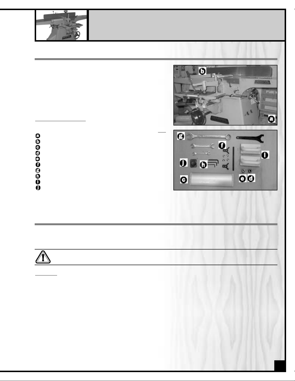
LIST OF CONTENTS
Qty
10” JOINTER . . . . . . . . . . . . . . . . . . . . . . . . . . . . . . . . . . . . . . . .1
FENCE ASSEMBLY . . . . . . . . . . . . . . . . . . . . . . . . . . . . . . . . . . .1
BLADE GUARD . . . . . . . . . . . . . . . . . . . . . . . . . . . . . . . . . . . . . .1
1/2” CHUCK . . . . . . . . . . . . . . . . . . . . . . . . . . . . . . . . . . . . . . .1
1/4” CHUCK . . . . . . . . . . . . . . . . . . . . . . . . . . . . . . . . . . . . . . .1
KNIFE SETTING GAUGE . . . . . . . . . . . . . . . . . . . . . . . . . . . . . . .1
WRENCHES . . . . . . . . . . . . . . . . . . . . . . . . . . . . . . . . . . . . . . . . .4
ALLEN KEYS . . . . . . . . . . . . . . . . . . . . . . . . . . . . . . . . . . . . . . . .3
PUSH BLOCKS . . . . . . . . . . . . . . . . . . . . . . . . . . . . . . . . . . . . . .2
CHUCK COVER . . . . . . . . . . . . . . . . . . . . . . . . . . . . . . . . . . . . .1
Carefully unpack and remove the unit and its components
from its shipping crate and check for missing or damaged
items as per the list of contents below.
Note: Please report any damaged or missing items to your
General International distributor immediately.
10” DELUXE JOINTER WITH MORTISER
80-250
UNPACKING
THE EQUIPMENT USED TO LIFT THIS MACHINE MUST HAVE A RATED CAPACITY AT, OR ABOVE THE WEIGHT OF THE
JOINTER. FAILURE TO COMPLY MAY CAUSE SERIOUS INJURY!
MACHINE PREPARATION AND ASSEMBLY
CLEAN UP
All unpainted surfaces are covered with a protective coating that prevents rust from forming during shipping and
storage. Remove this protective coating by rubbing with a rag dipped in kerosene, mineral spirits or paint thinner.
(Dispose of potentially flammable solvent-soaked rags according to manufacturer’s safety recommendations.)
A putty knife, held flat to avoid scratching the surface, may also be used to scrape off the coating followed by
clean-up with solvent. Avoid rubbing the machine’s painted surfaces, as many solvent-based products will remove
paint.
Also clean all moving parts or sliding contact surfaces that are coated. Loosen the fence lock handle, and remove
the fence from the head of the jointer.
Clean the sliding surfaces and re-install the fence on the head of the jointer.
5
For your convenience this unit is shipped from the factory partially assembled and requires minimal assembly
and set up before being put into service.
Page 6
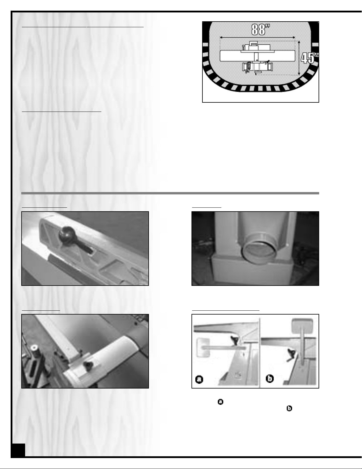
SHOP PLACEMENT / SPACE CONSIDERATIONS
The unit should be installed on a flat, sturdy and stable surface that
is able to support the weight of the unit (903 LBS) as well as the weight
of the operator. Most concrete slab type floors will be suitable but
some residential floors may require reinforcement.
Consider the space needed for the unit and its intended use when
deciding where to install your jointer/mortiser in your shop.
Extra space will be required for stock handling off the ends of both
the infeed and outfeed tables.
EST
ABLISHING A SAFETY ZONE
For shops with frequent visitors or multiple operators, it is advisable to establish a Safety Zone around shop machinery. A clearly de-fined “no-go”zone on the floor around each machine can help avoid accidents that could cause
injury to either the operator or the shop visitor. It is advisable to take a few moments to either paint (using non-slip
paint) or using tape, define on the floor the limits or perimeter of each machines safety zone. Take steps to ensure
that all operators and shop visitors are aware that these areas are off limits whenever a machine is running for
everyone but the individual operating the unit.
FENCE TILT LEVER
Install the fence tilt lever as shown.
DUST POR
T
Install the dust port as shown.
BLADE GU
ARD
TO INSTALL THE BLADE GUARD:
1. Loosen the knob on the arm of the blade
guard.
2. Insert the blade guard into the slot on the
bracket.
RE-POSITION
THE SWITCH
For shipping purposes the switch is mounted
as shown . Remove the four mounting bolts
and reposition the switch as shown using the
same bolts.
6
JOINTER ASSEMBLY
Page 7
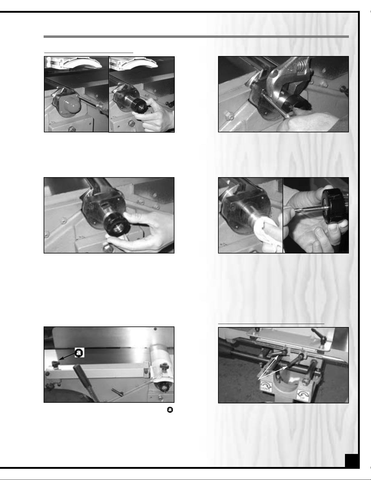
ASSEMBLING THE MORTISER
1. Raise the blade guard, remove the chuck
cover & screw the shaft with chuck into the
cutterhead.
TO INSTALL THE MORTISING CHUCK
2. Align the hole on bearing housing and cutterhead, using a screwdriver & insert and fix
in position. Hold the shaft,using an open end
wrench & tighten the shaft by turning clock
wise.
3. Turn the chuck counter clockwise and remove, as shown. Place the collet into the chuck
until it is secured.
4. Clean the inside of shaft with a rag. Screw
the chuck into the collet by turning 4 - 5
rotations and insert a bit. Hold the flat side
of the chuck, using an open end wrench.
Hold the chuck, using the ER25 wrench &
secure the bit by turning clockwise.
5. Press down the blade guard, turn the knob
clockwise until the guard sits close to the
table.
T
O MOUNT THE MORTISER TO THE JOINTER
1. With the help of an assistant, lift the mortiser
to the jointer. Before mounting the mortiser,
be sure the 2 lock levers on the mortiser are
fixed firmly. If not, turn them clockwise until
well tightened.
lock levers
7
Page 8
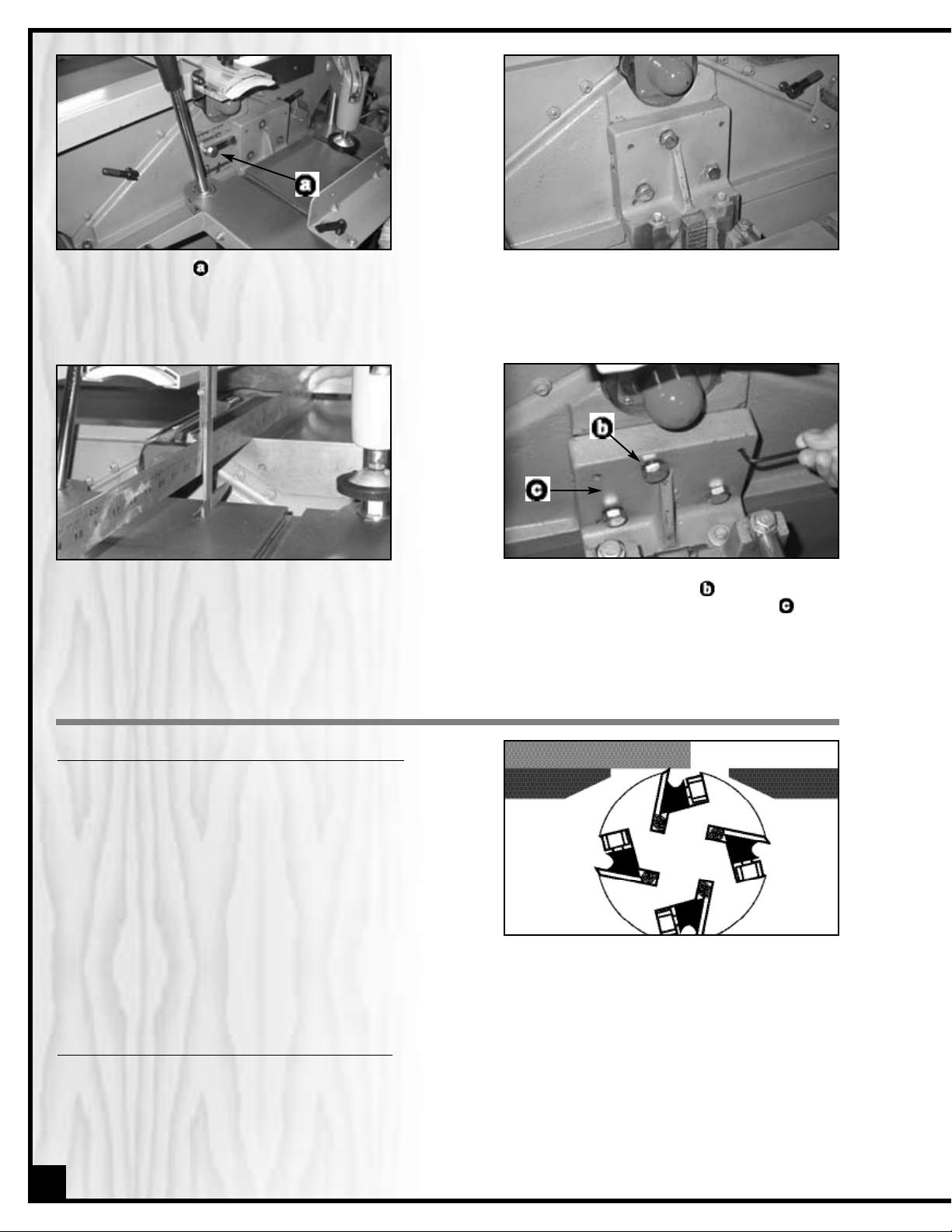
2. Align the T-slot,
,
on the mortiser to the slot
on the jointer until it is to the right position.
3. Align the 3 bolt holes on the jointer and using
a wrench, secure the mortiser to the jointer
with the bolts 3/8”.
4. Raise the mortiser table to the highest
position; place a straightedge and caliper
onto the jointer table and mortiser table to
check if tables are parallel.
5. If the tables are not parallel, using a wrench,
loosen three bolts 3/8”, , and using Allen
key, adjust the 5/16” set screws, , until
the tables are parallel to each other. Then
tighten the three 3/8” bolts.
ADJUSTMENTS & SETTINGS
ADJUSTING AND SETTING THE OUT-FEED TABLE HEIGHT
The outfeed table should be set level with the highest point of
the knives.
1. Set a straightedge onto the table so that it sits over the cutterhead but does not completely cross the gap between
the tables and touch the in-feed table.
2. Turn the cutterhead by hand, until any one of the knives is
at it’s highest point.
3. Release the table locking lever and turn the handwheel
(under the table) to raise or lower the table.
4. Adjust the table height so that the knife barely touches the straightedge.
5. Tighten the table locking lever to secure the table in position.
ADJUSTING
AND SETTING THE IN-FEED TABLE HEIGHT
The in-feed table should be set to the desired depth of cut for the operation being performed. Refer to the recommended dept of cut settings as mentioned in the section of specific jointer operating instructions.
1. Always loosen the table locking lever before turning the table adjustment hand wheel.
2. Once the table has been set to the desired height, don’t forget to retighten the locking lever to secure the table
in position.
STRAIGHTEDGE
OUTFEED
(left) Table
INFEED
(right) Table
8
Page 9

SETTING THE DEPTH OF CUT INDICATOR
As needed the depth of cut indicator can be readjusted.
1. Set a straightedge onto the out-feed table so that it sits over
the cutterhead and crosses the gap between the tables to
touch or sit above the in-feed table.
2. Release the table locking lever and turn the handwheel
(under the in-feed table) to raise or lower the table until the
in-feed table is level with the outfeed table.
3. Loosen the 2 screws and adjust the scale left or right until the
pointer is set to the zero ø point on the scale, then retighten the screws.
STRAIGHTEDGE
Outfeed (left) Table
SETTING THE FENCE STOPS
The fence stops allow you to position the fence at specific pre-set angles in relation to the tables without having to
measure each time you return to that angle. Due to wear and vibration, fence stops can over time become misaligned and should be checked periodically and re-set if necessary.
To set the 45° inward fence stop:
1. Using a 45° combination or machinists square, set the fence
to 45° inward.
2. Loosen the jam nut.
3. Adjust the 45° inward fence stop nut until it makes contact
with the back of the fence bracket.
4. Retighten the jam nut.
To set the 90° fence stop:
1. Using a 90° combination or machinists square, set the fence
to 90°.
2. Flip the 90° stop into the position.
3. Loosen the jam nut on the 90° fence stop bolt.
4. Adjust the 90° fence stop bolt until it makes contact with the
90° stop.
5. Retighten the jam.
Infeed (right) Table
To set the 45° outward fence stop:
1. Using a combination or machinists square, set the fence to
45° outward.
2. Loosen the jam nut on the 45° outward fence stop bolt.
3. Adjust the 45° outward fence stop bolt until it makes contact
with the back of the fence.
4. Retighten the jam nut.
ADJUSTING THE GIBS
The table gibs allow for you to eliminate excessive movement
or play in the tables and when properly adjusted, allow for easy
up and down movement.
1. On either of the tables, loosen the two gib nuts on the front
face of the jointer head.
2. Tighten both gib set screws an equal amount, and then
check the table by turning the handwheel to move it both
up and down. Continue to adjust the set screws as needed
until you find the right balance between easy movement
and minimal play.
3. Repeat these steps for the other table and then verify and adjust (if necessary) the outfeed table height as per
the steps listed in the section entitled “Adjusting and setting the Out-Feed Table Height”.
9
Page 10

KNIFE SETTING OR REPLACEMENT
Properly setting all four knives is essential to achieving accurate
work results. Properly set knives will last longer and also keep
their edge (sharpness) longer by equally sharing the cutting
workload.You may use the supplied knife setting gauge to help
you set the knives to the correct height whenever re-setting or
changing knives.
Note: If you prefer you may also find other “aftermarket” gauges,
jigs or knife setting tools that are to your liking – ask your local
tool distributor for information on any such tools that may be
available in your market.
The cutterhead on this unit is supplied with both adjustment
springs and jack screws providing you with two options for setting the knives. We suggest you try each method at least once or twice and decide for yourself which method works
best and fastest for you.
1. Turn off and disconnect the machine from the power source.
2. To give yourself unimpeded access to the cutterhead and knives, raise or remove the
blade guard and lower the tables as far as they go.
3. Rotate the cutterhead to access one of the knives.
4. Loosen (but don’t remove) all the gib bolts – start in the center and alternate sides
(If replacing an old or damaged knife, loosen the bolts until the knife can be removed
and install a new sharpened knife). Then position the gauge over the selected knife.
5. a) To use the Jack Screws to set the knife height use an allen wrench to turn the screws
to raise or lower the knife as needed until the ideal position - both sets of feet of the
gauge sitting flush on the cutterhead and the knife barely touching the center reference
pads on the gauge – has been achieved. Repeat for the other 3 knives.
b) To use the adjustment springs to set the knife height, push the knife down with the gauge so that the edge
of the knife is touching the center reference pads on the gauge. Hold the gauge down and tighten the bolts
to secure the knife in place. Repeat for the other 3 knives.
6. Re-check the height setting on all the knives and re-set as if necessary.
7. Reset the tables and replace the blade guard.
Note: After changing or resetting the knives the outfeed (left) table height must be re-adjusted to the match new
height of the knives. Follow the steps listed in the section entitled “Adjusting and setting the Out-Feed Table Height”.
This is also a good opportunity to verify and if needed re-set the depth of cut indicator. Follow the steps listed in the
section entitled “Setting the Depth of Cut Indicator”.
10
CHECKING KNIVES
ALWAYS DISCONNECT THE MACHINE FROM THE POWER SOURCE BEFORE SERVICING OR MAKING ADJUSTMENTS.
FAILURE TO HEED THIS WARNING CAN LEAD TO SERIOUS PERSONAL INJURY.
Accurate work results can only be achieved when all four
knives are properly installed and set to the exact same height
in the cutterhead. To verify if the knives are set properly, use the
supplied knife setting gauge following the steps below for each
of the four knives:
1. Turn off and disconnect the machine from the power source.
2. To give yourself unimpeded access to the cutterhead and
knives, raise or remove the blade guard.
3. Using the table height adjustment wheels lower the tables
enough to allow the knife setting gauge to fit fully on the
cutterhead.
4. Set the gauge onto the cutterhead with the center reference pads of the gauge sitting directly above a knife.
5. Observe how the gauge sits on the cutterhead and how/if the knife touches the center reference pads. The
ideal position has both sets of feet of the gauge sitting flush on the cutterhead and the knife barely touching
the center reference pads on the gauge.
6. Should any (or all) of the knives not be set properly proceed to the next section: “Knife Setting or Replacement”
Page 11

BASIC JOINTING OPERATIONS
SURFACE PLANING
1. Set & lock the fence at 90°.
2. Inspect the stock before starting & remove any foreign
objects or debris.
3. Set the depth of cut as required (1/32" is recommended
for face planing - Less for hard wood or wider stock.)
4. If your workpiece cupped, place the cupped side face
down on the infeed (right) table.
5. Turn on the machine & using push blocks press the stock
against the table and tight to the fence, feeding the stock
over the cutterhead.
6. Inspect the board & repeat the steps if needed until the surface is flat.
FAILURE TO USE PUSH BLOCKS MAY RESULT
IN SERIOUS PERSONAL INJURY. ALWAYS USE
PUSH BLOCKS TO HELP KEEP YOUR HANDS
AT A SAFE DISTANCE FROM THE KNIVES.
EDGE JOINTING
1. Set & lock the fence at 90°
2. Inspect the stock before starting & remove any foreign
objects or debris.
3. Set the depth of cut as required (1/16" - 1/8” is recommended for edge jointing - Less for hard wood or wider
stock.)
4. If your workpiece cupped, place the cupped side face
down on the infeed (right) table.
5. Turn on the machine & using push blocks press the stock
against the table and tight to the fence, feeding the stock over the cutterhead.
6. Inspect the board & repeat the steps if needed until the surface is flat.
BEVEL CUTTING
1. Set & lock the fence at the desired angle.
2. Inspect the stock before starting & remove any foreign
objects or debris.
3. Set the depth of cut as required (1/16" - 1/8” is recommended for bevel cutting - Less for hard wood or wider
stock.)
4. If your workpiece is cupped (curved), place it so the concave side is face down on the surface of the infeed
table.
5. Turn on the machine & using push blocks press the stock against the table and tight to the fence, feeding the
stock over the cutterhead.
6. Inspect the board & repeat the steps if needed.
RABBETING
1. Remove the blade guard & move the fence forward leaving only the width of the desired rabbet on the tables
uncovered by the fence & lock the fence in position.
2. Inspect the stock before starting & remove any foreign objects or debris.
3. Set the depth of cut as required (1/16" - 1/8” is recommended for rabbeting - Less for hard wood or wider
stock.)
4. Turn on the machine & using push blocks press the stock against the tables rabbeting arm and tight to the
fence, feeding the stock over the cutterhead.
5. Repeat the steps until the rabbet is cut to desired depth.
REMOVE THE BLADE GUARD FOR RABBETING ONLY. IMMEDIATELY REPLACE THE BLADE GUARD WHEN FINISHED. DO NOT
PERFORM ANY OTHER JOINTING OPERATION WITH THE BLADE GUARD REMOVED. FAILURE TO HEED THIS WARNING CAN
LEAD TO SERIOUS PERSONAL INJURY.
11
Page 12

1. Loosen handle,
, move the table outward then tighten.
2. Place the workpiece on the mortiser table, adjust the fence,
,
against the workpiece as required. Adjust the hold down,
,
keeping the workpiece in position.
3. Adjust the table to the required height to required position
with the handwheel, . Turn clockwise for down and counter clockwise for up.
4. Adjust the right and left lock levers,
,
to set the mortise
width.
5. Turn the key on the control panel to the ON position, press the
Start button. Make sure the mortiser function is lit, . If not,
press the Emergency Stop Button & make sure the machine is completely OFF.
6. Check the “Forward-Reverse Control”which is located at the
rear of machine. Turn it to the opposite direction, .
7. Restart the machine.
8. Loosen handle,,and slide the table until the workpiece
just touches the bit. Note the number on the depth scale,
then continue forward to the required depth by deducting
the required depth of the mortise from the noted number
from initial contact with the bit.
9. Slide the handle,,right to left to complet the mortise.
10. Turn off the machine when finished.
REPEA
T MORTISING:
1. Place a finished workpiece on the mortising table.
2. Loosen the handles,
,
counter clockwise & adjust both
handles until they are close to workpiece edge.
3. Tighten the two handles,,clockwise.
4. Repeat procedure step 7 to step 10 to make the mortising
operation.
MORTISING
12
Page 13

To prolong the service life of your jointer/mortiser and to maintain optimum performance the following basic maintenance procedures should be practiced and become part of your shop routine.
Keep the unit clean - After each use wipe or vacuum off all dust or woodchips on or around the machine.
Periodically apply (as directed) General International “Top Saver” #GC-010 or similar after market surface protectants to prevent rust and to protect all unpainted cast iron surfaces.
Inspect the belts regularly – To avoid potentially costly downtime, consider keeping a spare set of replacement
belts on hand for use if needed. Belts that show visible signs of wear such as cracks, fraying at the edges should be
replaced immediately.
Lubrication – All bearings are sealed and permanently lubricated and no further lubrication is required. The fence
assembly and table ways also should not be lubricated. If you should encounter a “sticking” problem, simply disassemble and clear away any obstructions from the ways.
PERIODIC MAINTENANCE
ALWAYS DISCONNECT THE MACHINE FROM THE POWER SOURCE BEFORE PERFORMING ANY MAINTENANCE. FAILURE
TO HEED THIS WARNING CAN LEAD TO SERIOUS PERSONAL INJURY.
RECOMMENDED OPTIONAL ACCESSORIES FOR YOUR JOINTER
We offer a large variety of products to
help you increase productivity, accuracy
and safety when using your jointer. Here’s
is but a small sampling of the accessories
that are available form your local
General International dealer.
Electronic Ear
muffs
99-200
Highly efficient noise
reduction to help protect
your hearing when
operating power tools.
Dust Collectors and
accessories
We offer a wide selection
of dust collectors and
accessories to suit virtually
all your shop needs. Dust
collectors contribute to a
cleaner healthier
workshop environment.
Jointer Push Block
80-120
Set of 2 hand paddle style
push blocks help to keep
hands clear of the cutter
heads while handling
and feeding stock through
the jointer.
13
Page 14

CIRCUIT DIAGRAM
14
Page 15
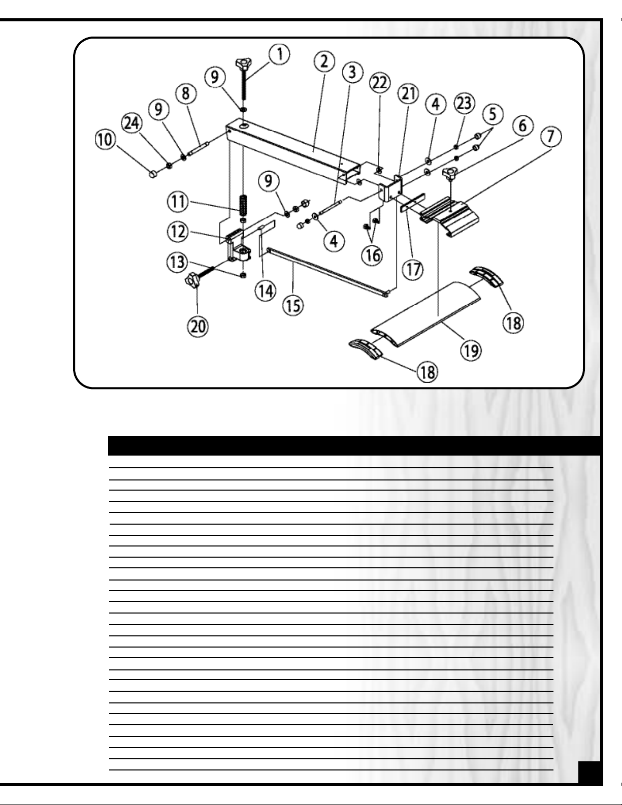
PARTS LIST
80-250
(Blade guard)
PART N0. DESCRIPTION SPECIFICATION QTY
80250-G01 LOCK KNOB 1
80250-G02 SUPPORT TUBE 1
80250-G03 THIN ROD 1
80250-G04 FLAT WASHER 6.4x1.5x1.6T 3
80250-G05 RUBBER CAP 3
80250-G06 KNOB 1
80250-G07 SLIDER BASE 1
80250-G08 THICK ROD 1
80250-G09 FLAT WASHER 8.5x16x1.8T 3
80250-G10 RUBBER CAP 2
80250-G11 SPRING 1
80250-G12 FIXED BLOCK 1
80250-G13 NUT M8x1.25P(13Bx6.5H) 2
80250-G14 PIN 6.0x18 1
80250-G15 LINK BAR 1
80250-G16 HEX. BOLT M5x0.8Px25 2
80250-G17 MOUNTING PLATE 1
80250-G18 END COVER 2
80250-G19 BLADE GUARD 1
80250-G20 KNOB 1
80250-G21 SUPPORT BRACKET 1
80250-G22 FLAT WASHER 6.7x16x1.0t 2
80250-G23 LOCK NUT M6x1.0P (10Bx7H) 3
80250-G24 LOCK NUT M8x1.25P (13Bx9H) 2
BLADE GUARD
15
Page 16

HEAD
16
Page 17

PARTS LIST
80-250
(Head)
PART N0. DESCRIPTION SPECIFICATION QTY
80250-01 FENCE SEAT 1
80250-02 FLAT WASHER 13X28X3T 6
80250-03 LOCK BOLT 1
80250-04 STOP 1
80250-05 PIN 1
80250-06 LOCK BOLT 1
80250-07 HEX. BOLT 1/4"-20UNCX1-1/4" 2
80250-08 HEX. NUT 1-4"-20NC 2
80250-09 BOLT 1
80250-10 SAFETY GUARD 1
80250-11 LINKING BAR 1
80250-12 LINKING BLOCK 1
80250-13 HEX. BOLT 5/16"-18NCX1-1/2" 1
80250-14 HEX. NUT 5/16"-18NC 1
80250-15 KNOB 1
80250-16 HANDLE 1
80250-17 BOLT 2
80250-18 HEX. NUT 3/8"-16NC 4
80250-19 COUNTERSUNK BOLT 5/16"-18NCX1-1/2" 1
80250-20 HEX. NUT 1-2"-20NC 2
80250-21 BOLT 2
80250-22 LINKER 1
80250-23 FENCE 1
80250-24 BOLT 2
80250-25 HEX. NUT 1
80250-26 FENCE BRACKET 1
80250-27 “T” NUT 1/2" 1
80250-28 KEY 9.5X9.5X300 2
80250-29 SPRING PIN 4X14 2
80250-30 COVER 1
80250-31 “ER” NUT 1
80250-32 “ER” COLLET 1
80250-33 SPINDLE 1
80250-34 BEARING HOUSING 1
80250-35 BEARING 6005-2NSE 1
80250-36 CUTTERHEAD 1
80250-37 SPRING 8
80250-38 COUNTERSUNK BOLT M5X0.8PX10 8
80250-39 KNIFE 4
80250-40 LOCK BAR 4
80250-41 SCREW 24
80250-42 CAP SCREW M8X1.25PX20 1
80250-43 LOCK WASHER 8.2X15.4X2T 1
80250-44 FLAT WASHER 1
80250-45 CUTTER PULLEY 1
80250-46 BEARING HOUSING 1
80250-47 BEARING 6204-2NSE 1
80250-48 KEY 5X5X30 1
80250-49 BOLT 2
80250-50 FLAT WASHER 4.3X10X1.0T 2
80250-51 LOCK WASHER 4.1X7.7 2
80250-52 SCREW 5/32"-32NC-5/8" 2
80250-53 OUTFEED TABLE 1
80250-54 CAP SCREW 1/2"-12NCX1-1/2" 2
80250-55 BASE 1
80250-56 INFEED TABLE 1
80250-57 HEX. NUT 5/16"-18NC 6
80250-58 SET SCREW 5/16"-18NCX1-1/4" 6
80250-59 BAR 2
17
Page 18

PARTS LIST
80-250
(Head)
PART N0. DESCRIPTION SPECIFICATION QTY
80250-60 SCREW 5/32"-32NC-3/8" 3
80250-61 POINTER 1
80250-62 LOCK LEVER 2
80250-63 SPRING PIN 6X20 2
80250-64 CAP SCREW 3/8"-16NC-2" 4
80250-65 FLAT WASHER 10.3X22X2T 4
80250-66 COUNTERSUNK BOLT 1/4"-20NC-3/4" 2
80250-67 WASHER 2
80250-68 FIXED PLATE 1
80250-69 SCALE SEAT 1
80250-70 BOLT 1
80250-71 PULLEY COVER 1
80250-72 KNOB 1
80250-73 SAFETY INDICATOR 1
80250-74 CAP SCREW 5/16"-18NC-3/4" 3
80250-75 LOCK PIN 1
80250-76 SPRING PIN 1
80250-77 BUSHING 1
80250-78 BALL HANDLE 1
80250-79 FIXED SEAT 2
80250-80 SPRING WASHER 10.2X18.5X2.5T 4
80250-81 CAP SCREW 3/8"-16NCX1-1/4" 4
80250-82 LEADER SCREW 2
80250-83 KEY 5X5X22 2
80250-84 BEARING 51103 2
80250-85 FIXED SEAT 2
80250-86 LOCK WASHER 13X22.7 4
80250-87 CAP SCREW 1/2"-12NCX1-1/2" 4
80250-88 BUSHING 2
80250-89 SET SCREW 1/4"-20NCX3/8" 4
80250-90 HAND WHEEL 2
80250-91 FLAT WASHER 8.5X16X2T 2
80250-92 HEX. SCREW M8X1.25PX12 2
80250-93 HANDLE 2
80250-94 “E” RING ETW-9 4
80250-95 BLADE GUIDE 2
80250-96 SHAFT 1
80250-97 WRENCH 8X10 1
80250-98 WRENCH 11X13 1
80250-99 WRENCH 17X19 1
80250-100 ALLEN WRENCH 5MM 1
80250-101 ALLEN WRENCH 4MM 1
80250-102 ALLEN WRENCH 3MM 1
80250-103 PHILLIPS SCREW DRIVER 6X100MM 1
80250-104 FLAT WASHER 6.6X13X1T 2
80250-105 SCREW 1/4"-20NCX3/8" 2
18
Page 19

19
MORTISER
Page 20

20
PARTS LIST
80-250
(Mortiser)
PART N0. DESCRIPTION SPECIFICATION QTY
80250-M01 COLUMN 1
80250-M02 BASE 1
80250-M03 TABLE 1
80250-M04 CROSS BASE 1
80250-M05 HEX. BOLT 3/8"-16NC-1=3/8" 3
80250-M06 LOCK WASHER 10.2X18.5 4
80250-M07 CAP SCREW 5/16"-18NC-3/4" 3
80250-M08 SCREW 1/4"-20NC-5/8" 3
80250-M09 LOCK WASHER 6.5X12.8 6
80250-M10 FLAT WASHER 6.7X19X2.0 7
80250-M11 LOCK SCREW 5/16"-18NC-7/8" 4
80250-M12 GEAR 1
80250-M13 RACK 1
80250-M14 SCALE BASE 1
80250-M15 LOCK SCREW 5/32"-32NC-3/8" 6
80250-M16 ROLLER 1
80250-M17 ROLLER SHAFT 1
80250-M18 BUSHING 2
80250-M19 SCREW 3/16"-24NC-1/2" 2
80250-M20 SCREW 1/4"-20NC-1/2" 2
80250-M21 BRACKET 1
80250-M22 SWIVEL BEARING 1
80250-M23 SETTING BLOCK 2
80250-M24 CONTROL BAR 1
80250-M25 HANDLE 1
80250-M26 RUBBER COLLAR 1
80250-M27 PLATE 1
80250-M28 COLUMN 1
80250-M29 COLUMN BASE 1
80250-M30 CAP SCREW 3/8"-16NC-1" 1
80250-M31 CAP SCREW 1/4"-20NC-3/4" 3
80250-M32 ARM 1
80250-M33 SPRING 1
80250-M34 SHAFT 1
80250-M35 UNIVERSAL HANDLE 7
80250-M36 ECCENTRIC HANDLE 1
80250-M37 PIN Ø8X30 1
80250-M38 COPPER PIN 1
80250-M39 SET SCREW 1/4"-20NC-3/8" 3
80250-M40 HEX. NUT 1/2"-12NC 1
80250-M41 SHORT ROLL 1
80250-M42 LONG ROLL 1
80250-M43 LINKING BLOCK 1
80250-M44 FENCE 1
80250-M45 SLIDER 2
80250-M46 SCREW M6X1.0PX12 4
80250-M47 FLAT WASHER 6.4X11.5X1.6 4
80250-M48 LOCK PLATE 2
80250-M49 SET SCREW 1/4"-20NC-1/2" 2
80250-M50 ROLLER 1
80250-M51 POINTER 2
80250-M52 RIVET 2
80250-M53 HEX. SCREW 5/16"-18NC-1" 8
80250-M54 CAP SCREW M6X1.0PX20 1
80250-M55 RAIL ROLLER 2
80250-M56 RAIL ROLLER 2
Page 21

21
PARTS LIST
80-250
(Mortiser)
PART N0. DESCRIPTION SPECIFICATION QTY
80250-M59 WING SCREW 1
80250-M60 HANDLE 1
80250-M61 CAP SCREW 1/4"-20NC-1/2" 1
80250-M62 FLAT WASHER 6.7X19X2 1
80250-M63 HANDWHEEL 1
80250-M64 COLLAR 1
80250-M65 SET SCREW M6X1.0PX8 1
80250-M66 SCALE BASE 1
80250-M67 POINTER 1
80250-M68 GEAR SHAFT 1
80250-M69 POINTER 1
80250-M70 RACK 1
80250-M71 COLLAR 2
80250-M72 LOCK WASHER 6.5X12.8 2
80250-M73 HEX. SCREW 1/4"-20NC-1=1/8" 2
80250-M74 GUIDE PLATE 1
80250-M75 LOCK NUT 3/8"-16NC 1
80250-M76 FLAT WASHER 10.3X23X2T 2
80250-M77 LINK PLATE 1
80250-M78 PIN 1
80250-M79 KEY 5X5X20 1
80250-M80 PIN 1
80250-M81 WORM GEAR 1
80250-M82 CAP SCREW 5/16"-18NC-1" 2
80250-M83 EXTENSION BAR 1
80250-M84 CONTROL HEAD 1
80250-M85 BUSHING 2
80250-M86 TUBE 1
80250-M87 POSITION SHAFT 1
80250-M88 SPRING 1
80250-M89 S RING STW-10 1
80250-M90 HANDLE 1
80250-M91 COVER 1
80250-M92 E RING ETW-9 1
80250-M93 SHAFT 1
80250-M94 SPACER 1
80250-M95 SCALE (R/L) 1
80250-M96 SCALE (F/B) 1
80250-M97 SCALE (U/D) 1
80250-M98 SCALE 1
80250-M99 SCALE 1
Page 22

22
PARTS LIST
80-250
(Base)
PART N0. DESCRIPTION SPECIFICATION QTY
80250-B01 CABINET 1
80250-B02 SCREW 5/32X32NCX1/4 4
80250-B03 DOOR 1
80250-B04 HEX. NUT 3/8"-16NC 1
80250-B05 DOOR LOCK 1
80250-B06 KNOB 1
80250-B07 SPONGE 2
80250-B08 SCREW 3/16"-24NC-1/2" 9
80250-B09 PLATE 1
80250-B10 DUST HOOD 1
BASE
Page 23

23
PARTS LIST
80-250
(Base)
PART N0. DESCRIPTION SPECIFICATION QTY
80250-B11 HEX. NUT 1/4"-20NC 2
80250-B12 ER WRENCH 1
80250-B13 LOCK PIN 1
80250-B14 CAP SCREW 1/4"-20NC-1=1/2" 2
80250-B15 WRENCH 1
80250-B16 CAP SCREW 3/8"-16NC-1=1/2" 4
80250-B17 SCREW 3/8"-16NC 4
80250-B18 SPRING PLATE 4
80250-B19 LOCK WASHER 4.1X7.7 8
80250-B20 SELF-TAPPING SCREW 5/32"-32NCX5/16" 8
80250-B21 PUSH BLOCK 2
80250-B22 SPONGE 4
80250-B23 YELLOW LIGHT AC240V __ 1
80250-B24 WHITE LIGHT AC240V __ 1
80250-B25 CONTROL PANEL 1
80250-B26 SCREW M4X0.7PX8 4
80250-B27 FLAT WASHER 4.3X12X0.8T 4
80250-B28 CONTROL BOX 1
80250-B29 CONTROL WIRE SJT 18AWGX4CX1.6M 2
80250-B30 LOCK 1
80250-B31 STOP BUTTON 1
80250-B32 START BUTTON 1
80250-B33 MAGNETIC SWITCH 3HP 220V~240V 1PH 1
80250-B34 SCREW 3/16"-24NC-3/4 6
80250-B35 REVERSING SWITCH 1
80250-B36 STRAIN RELIEF M-20 4
80250-B37 MOTOR WIRE SJT12AWGX3CX960MM 1
80250-B38 WIRE 12AWGX5CX500MM 1
80250-B39 SPONGE 4
80250-B40 SPONGE 4
80250-B41 SCREW M5X0.8PX10 6
80250-B42 STRAIN RELIEF ACC-2.5 2
80250-B43 SUPPORT 1
80250-B44 HEX. SCREW 3/16"-24NC-1/2" 4
80250-B45 LOCK WASHER 5.1X9.3X1.3 4
80250-B46 PROTECTIVE RING 20X25X2.5 3
80250-B47 POWER CORD SJT12AWGX3CX3300MM 1
80250-B48 HEX. NUT M8X1.25P(13BX6.5H) 8
80250-B49 FLAT WASHER 8.5X23X2T 8
80250-B50 SET SCREW 1/4"-20NCX3/4 4
80250-B51 ADJUSTMENT BOLT 2
80250-B52 FLAT WASHER 13.5X32X3T 4
80250-B53 HEX. NUT M12X1.75P 4
80250-B54 SHAFT 2
80250-B55 COLLAR 4
80250-B56 MOTOR BASE 1
80250-B57 VIBRATION RELEASE 4
80250-B58 V BELT M50 3
80250-B59 MOTOR 3HP 220~240V 1PH 60HZ 1
80250-B60 KEY 5X5X30 1
80250-B61 SET SCREW M6X1.0PX10 2
80250-B62 MOTOR PULLEY 1
Page 24

IMPORTANT: When ordering replacement parts, always give the model number, serial number of
the machine and part number. Also a brief description of each item and quantity
desired.
80-250
8360, Champ-d’Eau, Montreal (Quebec)
Canada H1P 1Y3
Tel.: (514) 326-1161
Fax : (514) 326-5565
Parts & Service
Fax : (514) 326-5555 Order Desk
orderdesk@general.ca
www.general.ca
 Loading...