

R
RESIDENTIAL AIR TREATMENT PRODUCTS
GENERALAire
INST ALLER: PLEASE FILL OUT AND MAIL GUARANTEE CARD AFTER INSTALLATION
IS COMPLETE. LEAVE INSTALLATION
PRECAUTION: The installer should be an experienced service technician. Disconnect electrical power before
beginning installation. Do not install where temperatures fall below 32 degrees F or where plenum temperatures
exceed 200 degrees F.
INSTALLATION: The humidifier may only be mounted on
the warm air plenum or furnace bonet. Humidifier extends
into duct 7 1/2 inches.
See Typical Installations.
INSTRUCTIONS WITH HOME OWNE R
WARM AIR
HIGH BOY
RETURN AIR
GENERALAire
HIGH EFFICIENCY AIR CLEANER
R
AC SERIES
MODEL 800
AUTOMATIC HUMIDIFIER
FOR INSTALLATION ON A
VERTICAL SURFACE OF ANY
WARM AIR PLENUM
RETURN AIR
WARM AIR
LOW BOY
1
Top Of Template
TEMPLATE FOR INSTALLING
GENERAL "800" HUMIDIFIER
FOLLOW INSTRUCTIONS PACKED WITH HUMIDIFIER
1. REMOVE PROTECTIVE PAPER FROM BACK OF TEMPLATE AND STICK IN LEVEL POSITION.
2. CENTER PUNCH AND DRILL THE FOUR SIDE MOUNTING HOLES WITH A 1/8 " DIA. DRILL.
3. HANG HUMIDIFIER FROM FOUR SIDE SCREWS AND INSTALL DRAIN PAN, EVAPORATOR
PAD AND DISTRIBUTOR TROUGH.
4. TIGHTEN SCREWS AND ADJUST HUMIDIFIER UNTIL LEVEL.
5. REMARK FOUR REMAINING HOLES IF NECESSARY.
6. REMOVE HUMIDIFIER, DRILL REMAINING HOLES AND CUT OUT CENTER SECTION OF
TEMPLATE.
CUT ON THIS LINE
TEMPLATE NO. 1042-25
2
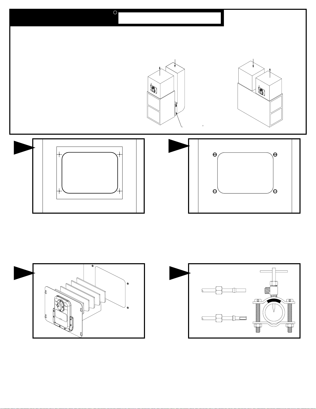
Select location on vertical surface of warm air plenum for
mounting humidifier. Stick mounting template in place
making sure the template is level. Do not install humidifier
where the blanked off ends of a cooling coil will restrict air
flow to the humidifier.
3 4
Center punch the four side mounting holes on the template
and drill with an 1/8" drill bit. Cut out center section of
template. Remove the template and insert the four sheet
metal screws until the heads project about 1/8".
COPPER
TUBING
Install evaporator plates in pan. Insert the humidifier in the
plenum such that the four screws project through the keyhole
slots. Slide the humidifier down level and tighten four screws.
PLASTIC
TUBING
Mount the self tapping saddle valve on either a cold or a hot
water pipe. A side or top mount is best to avoid clogging
from pipe sediment. Connect 1/4” O.D. tubing to the saddle
valve. Copper tubing requires a brass compression nut and
brass sleeve. Plastic tubing requires a brass insert inside the
tubing, a plastic sleeve on the outside with a brass
compression nut.
NOTE: DO NOT USE PLASTIC TUBING ON HOT WATER
OR IN CONTACT WITH ANY HOT PLENUM SURFACE OR
DUCT. INSTALLATION OF THIS SADDLE VALVE MUST
MEET OR EXCEED LOCAL CODES AND ORDINANCES.
SADDLE VALVE INSTALLATION INSTRUCTIONS
Copper Pipe
1. Retract piercing pin into valve body by turning handle
counterclockwise.
2. Screw valve body into upper bracket and tighten.
3. Place rubber gasket over piercing pin.
4. Assemble saddle valve over copper pipe using enclosed screws,
nuts and lower bracket.
5. Tighten screws evenly and firmly. Brackets should be parallel.
6. Complete compression connection to saddle valve outlet.
7. Turn handle clockwise to pierce tubing and close saddle valve.
8. Turn handle counterclockwise to
several seconds to flush dirt from pipe and tubing.
Steel, Brass or Hard Plastic Pipe
1. Shut off water supply and drain pipe.
2. Turn handle clockwise to expose piercing pin and close saddle valve.
3. Place rubber gasket over piercing pin.
4. Drill 1/8" hole in pipe using a hand crank drill to avoid shock hazard.
5. Assemble saddle valve over steel, brass or hard plastic pipe using
enclosed screws, nuts and lower bracket.
6. Tighten screws evenly and firmly. Brackets should be parallel.
7. Complete compression connection to saddle valve outlet.
8. Turn handle counterclockwise to
several seconds to flush dirt from pipe and tubing.
Threaded Pipe Fittings
1. Turn handle clockwise to expose piercing pin and close saddle valve.
2. Seal valve body threads using pipe tape or sealant.
3. Install valve into 1/8" NPT fitting.
4. Complete compression connection to saddle valve outlet.
5. Turn handle counterclockwise to
several seconds to flush dirt from pipe and tubing.
open saddle valve, leave open for
open saddle valve, leave open for
open saddle valve, leave open for
5
Connect 1/4" water supply tube to humidifier. Copper tubing
requires a brass compression nut and brass sleeve. Plastic
tubing requires a brass insert inside the tubing, a plastic
sleeve on the outside with a brass compression nut.
DO NOT USE PLASTIC TUBING IN CONTACT WITH
ANY HOT PLENUM SURFACE OR DUCT. IF USING
PLASTIC TUBING, USE TUBE SUPPORT
PROVIDED.
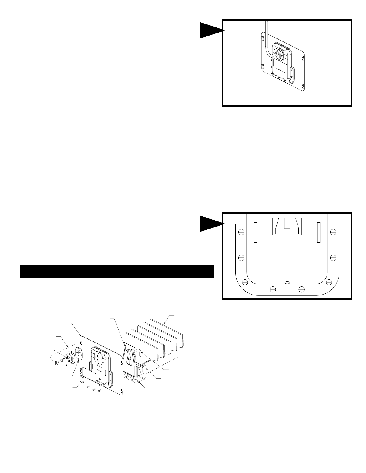
PARTS LIST FOR HUMIDIFIER
FACE PLATE
800-M
VALVE BODY REPAIR KIT
896
SCREEN DISC
800-N
VALVE DIAPHRAGM
800-DM
INSPECTION PLATE
800-E
ADJUSTING SCREW
800-L
6
880
EVAPORATOR
PLATES
(Set of 5)
DRIP TUBE
800-K
EVAPORATOR PAN
800-IJ
ACTUATOR PLATE & PAN
DIAPHRAGM ASSEMBLY
800-GMF
Turn on water supply and check operation of humidifier. Check
flow of water by removing inspection plate and observe drip
tube. Humidifier will gradually fill 3/4 inch to 1 inch deep and
shut off. To accelerate filling, move valve actuator plate
toward pan through inspection opening.
NOTE: THIS HUMIDIFIER HAS BEEN FACTORY ADJUSTED
TO OPERATE ON WATER PRESSURES FROM 20 TO 150
P.S.I. NO ADJUSTMENT SHOULD BE NECESSARY.
NOTE: 800-IJ phenolic evaporator pan with
cast in plate rack and pan baffle is
interchangeable with 800-I pan.
FORM NO. 800-II Rev. C (FILE 10238) Litho in U.S.A.

CARE AND MAINTENANCE
Your Humidifier is engineered to give helpful and trouble-free humidification. For maximum efficiency the following cleaning procedures should be carried
out at the end of each heating season:
REPLACING EVAPORATOR PLATES AND CLEANING HUMIDIFIER
1. Turn off water supply to humidifier.
2. Disconnect the 1/4” water supply line from the humidifier.
3. Loosen the four screws holding the humidifier in place.
4. Lift humidifier up and slide out.
5. Remove old evaporator plates.
6. Clean pan with scouring pad and rinse thoroughly.
7. Replace evaporator plates with Generalaire 880 evaporator plates.
8. Carefully slide humidifier into opening to prevent breaking evaporator
plates.
9. Tighten the four screws and reconnect the 1/4” water line to the
humidifier. Turn on the water supply and check all points for leakage.
The humidifier is now ready for operation.
10. During the summer, turn off water supply to humidifier.
DO NOT DISTURB VALVE ASSEMBLY UNLESS IT SHOULD FAIL TO
FUNCTION PROPERLY.
SERVICING THE VALVE
If the valve should malfunction look for dirt in the orifice and neoprene
valve seat.
A. Turn off water supply to humidifier. Disconnect the 1/4” water supply
line from the humidifier. Loosen the four screws holding the humidifier in
place. Lift humidifier up and slide out.
B. Remove the four screws from the valve body and pull from neoprene
valve diaphragm.
C. Remove screen disc from orifice fitting with wire paper clip. Clean
orifice and screen.
D. Clean all dirt and scale frame neoprene valve seat and examine seat
for wear.
E. Replace valve body with orifice fitting on top. Do not over tighten
screws.
F. Reconnect the 1/4” water line to the humidifier. Turn on water supply
and adjust valve to shut off when water level is approximately 1/4 inch
above holes in pan baffle. When the water reaches this level turn valve
adjusting screw in slowly until water stops dripping from drip tube. To test
this setting dip water from the pan. Water should start dripping from the
drip tube. The humidifier is now properly adjusted to automatically
maintain this water level in the pan.
HOW THE HUMIDIFIER WORKS
The water supply to the humidifier is automatically controlled by the water
pressure against the neoprene pan diaphragm.
When the water level is approximately 1 inch deep in the pan, the pressure
on the pan diaphragm causes the actuator plate to pivot pushing the screw
and valve seat against the orifice, shutting off the flow of water.
As the water is drawn from the pan and evaporated through the evaporator
plates, the pressure on the pan diaphragm is reduced, allowing the actuator
plate to pivot away from the valve, opening the water inlet orifice. This
allows water to flow from the orifice through the valve chamber and drip
tube to refill the pan.
FILL OUT AND MAIL THIS
WARRANTY CARD AND
LITERATURE REQUEST FORM
AIRC
H
D
AIRF
F
A
LEANERS AND AIRPURIFIERS
UMIDIFIERS
IGITALHUMIDITYGAGE
ILTERGAGE
UELOILFILTERS AND
CCESSORIES

LIMITED WARRANTY
This humidifier, if properly registered by the return of the warranty registration card to the manufacturer, is warranted to the consumer against defects in
materials and workmanship for a period of one year from the date of installation. Evaporator pads, sleeves or plates are not covered by this limited
warranty or any other warranties. Any other defective parts will be repaired without charge except for removal, reinstallation and transportation costs. To
obtain repair service under this limited warranty, the consumer must send the defective part or the complete humidifier to the manufacturer.
THERE ARE NO EXPRESS WARRANTIES COVERING THIS HUMIDIFIER OTHER THAN AS SET FORTH ABOVE, THE IMPLIED WARRANTIES OF
MERCHANTABILITY AND FITNESS FOR A PARTICULAR PURPOSE ARE LIMITED IN DURATION TO ONE YEAR. THE MANUFACTURER
ASSUMES NO LIABILITY IN CONNECTION WITH THE INSTALLATION OR USE OF THIS PRODUCT, EXCEPT AS STATED IN THIS LIMITED
WARRANTY. THE MANUFACTURER WILL IN NO EVENT BE LIABLE FOR INCIDENTAL OR CONSEQUENTIAL DAMAGES.
This limited warranty gives you specific legal rights, and you may also have other rights which vary from state to state. Some states do not allow either
limitations on implied warranties, or exclusions from incidental or consequential damages, so the above exclusion and limitation may not apply to you.
Any questions pertaining to this limited warranty should be addressed to the manufacturer. (U.S.A.: The manufacturer has elected not to make available
the informal dispute settlement mechanism which is specified in the Magnuson-Moss Warranty Act.).
GENERAL FILTERS, INC. 43800 GRAND RIVER AVE. NOVI, MICHIGAN 48375-1115 WWW.GENERALAIRE.COM
CANADIAN GENERAL FILTERS, LTD. 39 CROCKFORD BLVD. SCARBOROUGH, ONTARIO M1R3B7 WWW.CGFPRODUCTS.COM
D
D
Ville:
ATE OF
ATE DE
I
I
NSTALLATION
NSTALLATION
Province:
S
Numéro de Série
ERIAL
N
UMBER
Code postal:
Adresse:
C
ITY
S
TATE
P
OSTAL
C
ODE
S
TREET
A
DDRESS
D
Nom du marchand:
Ville:
EALER'S
N
AME
Province:
Code postal:
Adresse:
C
ITY
S
TATE
P
OSTAL
C
ODE
LE PROPRIÉTAIRE DOIT REMPLIR LA CARTE
D'ENREGISTREMENT
ET LA POSTER AU :
OWNER FILL IN
REGISTRATION
AND MAIL TO:
O
Nom du propriétaire:
S
TREET
A
DDRESS
MODEL 800 AUTOMATIC HUMIDIFIER
AUTOMATIQUE HUMIDIFICATEUR MODÈLE 800
WNER'S NAME
WARRANTY REGISTRATION
Enregistrement de la garantie
GENERAL FILTERS, INC.
43800 GRAND RIVER AVE.
NOVI, MI 48375-1115
 Loading...