

Page 1
© Copyright General International 08/2007
REVISION 2 - NOVEMBER 15/07
Page 2
THANK YOU
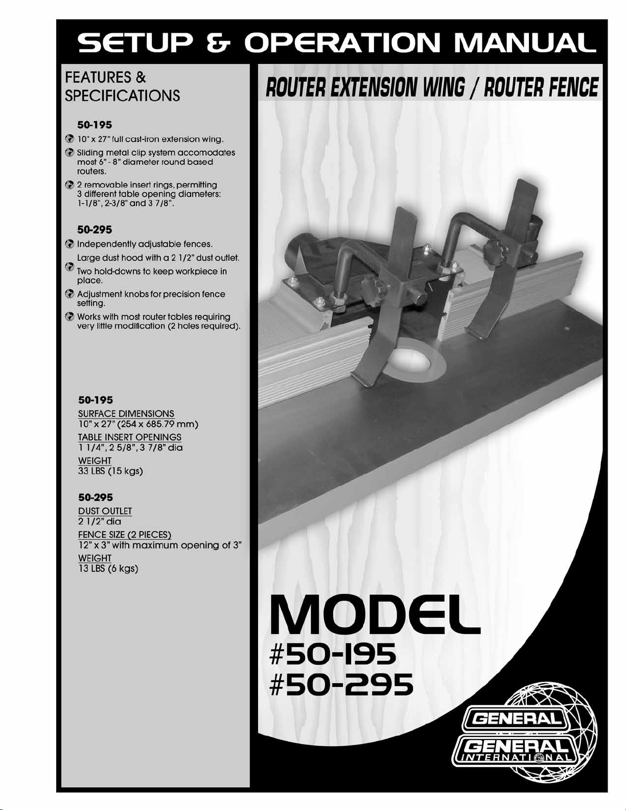
for choosing this General® International model 50-195/50-295
Router Extension Wing/Router Fence.This router extension wing/router fence has been carefully
tested and inspected before shipment and if properly used and maintained, will provide you
with years of reliable service. To ensure optimum performance and trouble-free operation, and
to get the most from your investment, please take the time to read this manual before assembling, installing and operating the unit.
The manual’s purpose is to familiarize you with the safe operation, basic function, and features
of this router extension wing/router fence as well as the setup, maintenance and identification
of its parts and components. This manual is not intended as a substitute for formal woodworking instruction, nor to offer the user instruction in the craft of woodworking. If you are not sure
about the safety of performing a certain operation or procedure, do not proceed until you
can confirm, from knowledgeable and qualified sources, that it is safe to do so.
Once you’ve read through these instructions, keep this manual handy for future reference.
All component parts of General® International machinery are carefully tested and inspected during all stages of
production, and each machine is thoroughly inspected upon completion of assembly. Because of our commitment to quality and customer satisfaction, General® International agrees to repair or replace, within a period of 24
months from date of purchase, any genuine part or parts which, upon examination, prove to be defective in workmanship or material. In order to obtain this warranty, all defective parts must be returned freight pre-paid to
General® International Mfg. Co., Ltd. Repairs attempted without our written authorization will void this warranty.
GENERAL ® INTERNATIONAL WARRANTY
Disclaimer:
The information and specifications in this manual pertain to
the unit as it was supplied from the factory at the time of printing.
Because we are committed to making constant improvements, General
International reserves the right to make changes to components, parts
or features of this/these unit(s) as deemed necessary, without prior
notice and without obligation to install any such changes on previously
delivered units. Reasonable care is taken at the factory to ensure that
the specifications and information in this manual corresponds with that
of the unit with which it was supplied. However, special orders and “after
factory” modifications may render some or all information in this manual inapplicable to your extension wing/fence. Further, as several generations of this model of router extension wing/router fence and several
versions of this manual may be in circulation, if you own an earlier or
later version of this/these unit(s), this manual may not depict your unit(s)
exactly.If you have any doubts or questions contact your retailer or our
support line with the model and serial number of your unit for clarification.
GENERAL® INTERNATIONAL
8360 Champ-d’Eau, Montreal (Quebec) Canada H1P 1Y3
Telephone (514) 326-1161 • Fax (514) 326-5555 • www.general.ca
Page 3
Rules for Safe Operation
To help ensure safe operation, please take a moment to learn the machine’s applications and limitations, as well as potential hazards. General® International disclaims any real or implied warranty and
holds itself harmless for any injury that may result from improper use of its equipment.
1. Make sure that the operator has been properly trained
and has read and understands the Owner’s Manual
before operating any machinery.
2. Be sure to read, understand,and follow all instructions,
warnings, and safety guidelines supplied with your
table saw and router.
3. Keep the work area well lit, clean, and free of debris.
4. STAY ALERT! Give your work you undivided attention.
Even a momentary distraction can lead to serious
injury.
5. Do not wear loose clothing, gloves, bracelets, neck-
laces, or other jewelry. Wear protective hair covering
to contain long hair and wear non-slip footwear.
6. Keep hands and other body parts well away from bits
or cutting tools. When working close to the cutting tool,
always use a feather board or push-stick to hold or
guide the workpiece. Do not clear chips and sawdust
away with hands; use a brush.
7. Fine particulate dust is a carcinogen that can be haz-
ardous to health. Always work in a well ventilated area
and whenever possible use a dust collector.
8. Be sure the router bit and/or saw blade has gained full
operating speed before feeding the workpiece.
9. Keep children and visitors at a safe distance when the
table saw is in operation – do not permit them to operate the table saw.
10. Childproof and taper proof your shop and all machin-
ery with locks, mater electrical switches and switch
keys, to prevent unauthorized or unsupervised use.
11. Never stand or lean on your table saw. Serious injury
can occur if the table saw is tipped or if unintentional
contact is made with the spinning saw blade or router
bit.
12. Keep all guards and safety devices in place and in
good working order. If a guard must be removed for
maintenance or cleaning make sure it is properly reinstalled before using the machine again.
13. Hold the workpiece firmly against the table and use
suitable support if the workpiece does not have a flat
surface.
14. Feed the stock into the bit against the rotation direc-
tion of the bit. Never run the stock between the fence
and the bit.
15. Do not operate the router with a damaged bit and/or
the table saw with a damaged blade.
16. Always disconnect the router and/or the table saw
from the power source before changing accessories
or before performing any maintenance and adjustments or if the machine will be left unattended.
17. Be sure that all adjustment tools, wrenches, or other
clutter are removed from the table surface and safely
stored before sawing or routing.
18. Make sure the router and/or table saw switch(es) is
(are) in the “OFF” position before plugging in to a power source.
19. Avoid working from awkward or off-balance positions.
Do not overreach and always keep both feet firmly on
the floor.
20. Never leave the table saw and/or router unattended
while running or with the power “ON”.
21. Do not use this router extension wing/router fence for
any purposes other than its intended use. If used for
other purposes, General® International disclaims any
real or implied warranty and holds itself harmless for
any injury which may result from such use.
Page 4
4
ROUTER EXTENSION WING / ROUTER FENCE
50-195 / 50-295 / 50-295CT
UNPACKING & SETUP
ROUTING MAY PRESENT SERIOUS INJURY HAZARDS TO UNTRAINED USERS. BE SURE TO READ, UNDERSTAND AND FOLLOW ALL INSTRUCTIONS AND SAFETY RULES SUPPLIED WITH YOUR ROUTER.
The router extension wing (Model #50-195) and router fence (Model #50-295) may be purchased either separately
or together as a kit (Model #50-295CT). Contact your General® International distributor for more information.
This manual contains instructions for both the router extension wing (Model #50-195) and the router fence (Model
#50-295). Depending on your purchase, some of the information in this manual may not apply.
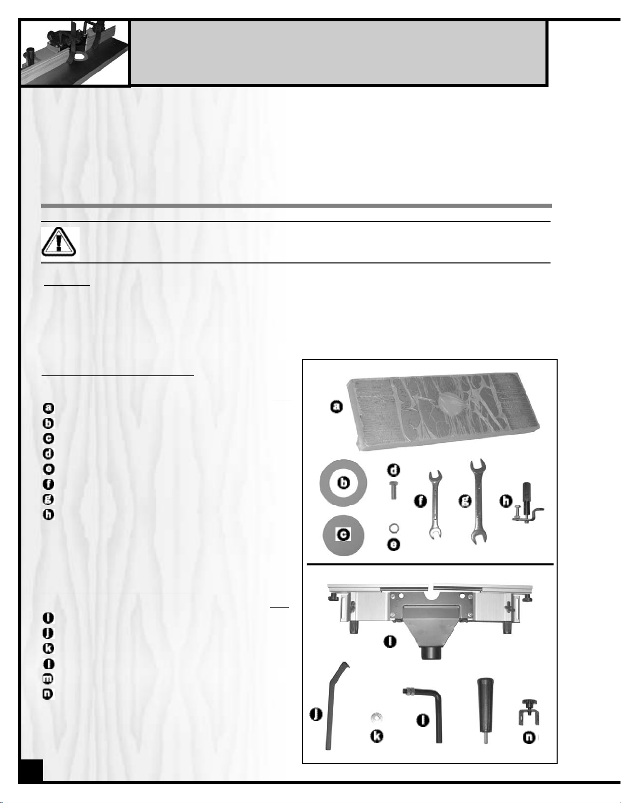
UNPACKING
Carefully unpack and remove the unit and its components from the box and check for missing or damaged items
as per the list of contents below.
Note: Report any missing or damaged items to your General® International distributor immediately.
LIST
OF CONTENTS
50-195
QTY
ROUTER EXTENSION WING
. . . . . . . . . . . . . . . . . .1
TABLE INSERT (60 MM)
. . . . . . . . . . . . . . . . . . . . .1
TABLE INSERT (29 MM)
. . . . . . . . . . . . . . . . . . . . .1
MOUNTING BOLTS
. . . . . . . . . . . . . . . . . . . . . . . . .3
LOCK WASHER
. . . . . . . . . . . . . . . . . . . . . . . . . . . .3
COMBINATION WRENCH (10 / 12 MM)
. . . . . . .1
COMBINATION WRENCH (14 / 17 MM)
. . . . . . .1
MOUNTING CLIP ASSEMBLY
. . . . . . . . . . . . . . . . .4
LIST OF CONTENTS 50-295
QTY
FENCE ASSEMBLY
. . . . . . . . . . . . . . . . . . . . . . . . .1
HOLD-DOWN PLATE
. . . . . . . . . . . . . . . . . . . . . . . .2
WASHER
. . . . . . . . . . . . . . . . . . . . . . . . . . . . . . . . .2
HOLD-DOWN SUPPORT ARM
. . . . . . . . . . . . . . . .2
HANDLE
. . . . . . . . . . . . . . . . . . . . . . . . . . . . . . . . .2
HOLD-DOWN BRACKET
. . . . . . . . . . . . . . . . . . . . .2
INCLUDED IN 50-195 PACKAGE
INCLUDED IN 50-295 PACKAGE
Page 5

TABLE TOP CLEAN UP
All unpainted surfaces are covered with a protective coating
that helps prevent rust from forming during shipping and storage. Remove the protective coating by rubbing with a rag
dipped in kerosene, mineral spirits, or paint thinner (Dispose of
potentially flammable solvent soaked rags according to manufacturer’s safety recommendations). A putty knife, held flat to
avoid scratching the surface, may also be used to scrape off
the coating followed by clean up with solvent.
Note: Avoid rubbing the painted surfaces, as many solventbased products will remove paint.
Fig. 1
INSTALLING THE ROUTER EXTENSION WING (50-195)
The router extension is designed to replace either of the existing
27” long wings (left or right) on your table saw. It is designed to
fit on General® International models 50-175/185 and 50-250/260
table saws without further modification. Deciding whether to
install the wing to the left or right end of the saw is entirely a matter of personal preference, and should be determined by your
own work habits and/or shop space considerations. Whichever
side you choose, make sure to leave adequate room to work.
(Fig. 2)
Note: Some cabinet style saws have motor cover doors that
extend underneath beyond the main table, thus preventing the
router from being hung from that side of the saw. In such cases
the model 50-195 router table must be installed on the side
opposite to the motor cover door.
Fig. 2
The unit can fit other models or brands of table saws with 27”
tables. It can also be added to the end of either existing wing
(see note below for further details), but additional mounting
hardware (not included) may be required. Should the predrilled
holes in the extension wing not line up with the existing holes in
the main table of your saw, clamp the extension wing in place
on the saw.Level the wing with the main table and line it up flush
with the front edge of the saw and with the clamps holding it
securely in place, drill matching holes into the main table
through the mounting holes in the wing (Fig. 3).
Note: When adding the 50-195 router extension wing to the end
of an existing table extension (rather than in place of the existing wing) keep in mind that the added weight of the wing will
affect the center of gravity of the saw making the saw heavier
on the side that the wing is installed on. This could increase the
possibility of a tip-over should a heavier piece of stock or sheet
goods be placed on the saw. (Fig. 4)
To reduce the possibility of a tip over, install support legs under
the router extension. A simple 2” x 4” cut to length from the floor
the underside of the table will provide the support need to help
prevent a tip over. (Fig. 4.1)
Attach the extension wing using the 3 hex head bolts and lock
washers finger tight at first (Fig. 5). Use a straightedge to ensure
that wing is level with table from front to back. Gently tap the
wing up or down, then tighten the bolts with the supplied
wrench, leaving the center bolt to be tightened last. Be sure that
the extension wing is flush with the front edge of the table.
Fig. 3
Fig. 4
Fig. 5
Fig. 4.1
5
Page 6

6
MOUNTING A ROUTER
Fig. 6 Fig. 7
Fig. 8
Fig. 9
4. Fit the router between the clips and the underside
of the table. Holding the router in place, tighten
one shoulder bolt and its diagonal opposite to
raise the clip to grip and tighten the router plate
to the table.
Fig. 10
Fig. 11
3. Continue adjusting until the space between the
clips and the underside of the table is slightly
wider then the thickness of your router base.
Note: In some cases, if the router base is too thin for
the clips to secure it, flat wooden shims or spacers
can be used between clips and the router base to
facilitate installation.
1. Slide the T-head bolts into the T-slots allowing them
to loosely hang from the underside of the table.
Line the mounting clips up straight with the slots so
that the rear bolt can fit in the slot when tightened.
Note: Use the inner slots for smaller diameter router
bases or the outer slots for larger bases.
5. Loosen, adjust, and retighten as needed until the
router is centered in the table opening.
6. With the router centered in the table opening,
tighten down all 4-shoulder bolts, , and make
sure all 4 mounting clips, , are securely holding the router to the underside of the table. Tighten the 4 stop nuts, , on the rear bolts to lock
down the clip system.
2. Adjust the rear bolts, , on the mounting clips
until they bottom out in the slots and tilt the front
edge of the clips forward.
Inner slots
Outer slots
Wooden shim or
spacer (may be
required)
Page 7

TABLE INSERT RINGS
The router extension wing (Model #50-195) comes with 2 removable insert rings allowing the opening on the extension wing to
be changed to suit the most common sizes of router bits.
The supplied rings come in two sizes: 1 1/8” (29 mm), 2 3/8”
(60 mm), allowing for three different table opening sizes.
The smallest opening is 1 1/8” (29 mm), the largest opening is
2 3/8”(60 mm) and with no insert ring installed the opening in the
wing measures 3 7/8”(98.5 mm).
Fig. 12
ASSEMBLING AND INSTALLING THE ROUTER FENCE (50-295)
Fig. 13
Fig. 14
Fig. 15
Fig. 16
1. Secure the router fence to the table at each end
by threading a washer and a handle into the
holes located closest to the edge of the table.
2. Remove one hex nut from each of the hold-down
support arms .
Note: You may have to loosen the horizontal fence
adjustment knobs and slide the fences apart to give
you enough clearance to easily complete the following steps (See section Fence Adjustments on
page 8 for instructions on moving the fence).
3. Fit the threaded ends of the hold-down support
arms through the holes on the dust hood secure
the support arms in place using the hex nut, ,
removed in step 2.
4. Slide a hold-down bracket into each of the holddown support arms. Slide a hold-down into the
hold-down bracket (make sure the legs of the
hold-downs are pointing against the rotation of
the router bit, see section “Using the workpiece
hold-downs”on page 8) and tighten using the
lock knob on the hold-down bracket.
Precise placement and postioning, of the holddown brackets or the hold-downs can be adjusted later and will vary depending on the height
and width of the workpiece.
7
1 1/8”(29 mm)
2 3/8”(60 mm)
Page 8

FENCE ADJUSTMENTS
The fences can be moved and adjusted both left and right and
are completely independent of one another.
Left/Right
Adjustment
Loosen the knob, , to manually move the fence left or right.
Once you have the fence at the desired position, retighten the
knob.
Front to Bac
k
Adjustment
Loosen the thumb screw, , on the top of the fence frame and
adjust the fence front to back using the adjustment knob, ,
Once you have the fence at the desired position remember to
lock the fence by tightening the thumb screw before use.
Note: For safety considerations, the two fences should be adjusted as close to the router bit as possible (without
touching the bit).
Fig. 17
CONNECTING A DUST COLLECTOR
There is a 2 1/2” dust outlet on the rear of the fence assembly allowing for the connection of a dust collector (not
included).
Be sure to use an appropriate size hose and fittings (not included) and check that all connections are sealed tightly to minimize airborne dust.
If you do not already own a dust collection system, consider contacting your General® International distributor for
information on our complete line of dust collection systems or visit our website at: www.general.ca
BEFORE ROUTING CONNECT THE UNIT TO A DUST COLLECTION SYSTEM.
ALWAYS TURN ON THE DUST COLLECTOR BEFORE STARTING THE ROUTER AND ALWAYS STOP THE ROUTER BEFORE
TURNING OFF THE DUST COLLECTOR.
OPERATING INSTRUCTIONS
MAKE SURE TO READ, UNDERSTAND, AND FOLLOW ALL OPERATING INSTRUCTIONS AND SAFETY GUIDELINES THAT
CAME WITH YOUR ROUTER – FAILURE TO DO SO MAY LEAD TO SERIOUS INJURY AND/OR DAMAGE TO THE ROUTER,
ROUTER TABLE, OR WORKPIECE.
BEFORE ST
ARTING:
• Install the required bit in your router according to the instructions supplied with your router.
• Make sure that the router is firmly attached to the router extension table and that the appropiate table insert ring
is properly fitted and level in the table opening.
• When jointing, and/or profile cutting always perform a test cut on a scrap piece of wood before routing your final
piece.
USING THE WORKPIECE HOLD-DOWNS
The 50-295 router fence comes with a pair of hold-downs to help
reduce the likelihood of kickback.
Install the hold-downs with its legs pointing against the rotation of
the router bit.
It’s important to remember the stock must
always be fed against the rotation of the router bit.
Make the hold-downs as tight as possible to the stock being fed
while still allowing it to move smoothly.
8
Fig. 18
Feed direction
Bit rotation
Loosen knobs
to adjust height
Page 9

JOINTING AN EDGE
Jointing the edge of a board involves using a straight cutting
router bit to remove wood from the edge face of a board. The
result is a perfectly flat and square edge.
1. Install a straight cutting router bit into your router according to
the manufacturer’s instructions.
2. Snap the smallest table insert into the recessed hole that still
allows the router bit to rotate freely.
3. Loosen the locking lever and using the fence adjustment
knob adjust the out-feed fence lever so that it is flush with
the edge of the router bit, for precision use a straightedge
(Fig. 19).
4. Loosen the knobs and adjust the opening between the fences to allow the bit to clear the edge of both fences.
5. Raise or lower the bit slightly so that the bit is higher than the board’s thickness.
6. Adjust the in-feed fence to the router bit center, so that the distance is equal to the desired depth of the cut.
Fig. 19
PROFILE CUTTING
Profile cutting is usually performed using a bit with a guide bearing. The guide bearing controls the depth of cut into the edge
face of a board. A good example would be a chamfer bit
(Fig. 21).
The bearing rides along the uncut edge of the board while the
cutter removes the wood.
1. Mount a router bit into your router according to the manufac-
turer’s instructions.
2. Snap the smallest table insert into the recessed hole that still
allows the router bit to freely rotate.
3. Raise or lower the router bit to the desired height.
4. Loosen the knobs and adjust the opening between the
fences to allow the bit to clear the edge of both fences.
5. Adjust the fence back and away from the bit only enough to
allow the guide bearing to control the depth of cut.
6. Adjust the fence as close as possible to the bearing. The
fence will serve as a backup support, reducing the chance of
an accident.
Fig. 20
Fig. 22
Fig. 21
NOTES
9
Page 10

10
PARTS LIST
50-195
REF. DIAG. PART N0. DESCRIPTION SPECIFICATION QTY
1 50195-01 ROUTER EXTENSION WING 1
2 50195-02 TABLE INSERT 1 1/4” (29 MM) 1
3 50195-03 LOCK WASHER 3
4 50195-04 MOUNTING BOLT 7/16” X 1 3/4” 3
5 50195-05 MOUNTING CLIP 4
6 50195-06 HEX. HEAD BOLT 1/4” X 1 3/4” 4
7 50195-07 HEX NUT 4
8 50195-08 T-HEAD BOLT 4
9 50195-09 SHOULDER BOLT 4
10 50195-10 COMBINATION WRENCH 10-12 MM 1
11 50195-11 COMBINATION WRENCH 14-17 MM 1
12 50195-12 TABLE INSERT 2 5/8” (60 MM) 1
ROUTER EXTENSION WING
Page 11

11
PARTS LIST
50-295
REF. DIAG. PART N0. DESCRIPTION SPECIFICATION QTY
1 50295-01 FENCE FACE 2
2 50295-02 FENCE MOUNTING PLATE 2
3 50295-03 WASHER 2
4 50295-04 MOUNTING HANDLE 2
5 50295-05 MICRO ADJUSTMENT SLEEVE 2
6 50295-06 FENCE BODY 2
7 50295-07 THUMB SCREW 3/8” X 3/4” 2
8 50295-08 FENCE BODY BACKER PLATE 2
9 50295-09 MICRO ADJUSTMENT KNOB 2
10 50295-10 HEX. HEAD BOLT 3/8” X 1 1/2” 2
11 50295-11 HOLD-DOWN 2
12 50295-12 HOLD-DOWN BRACKET 2
13 50295-13 HOLD-DOWN SUPPORT ARM 2
14 50295-14 LOCK KNOB 5/16” X 5/8” 2
15 50295-15 HEX. NUT 1/2” 4
16 50295-16 DUST COVER 1
16A 50295-16A DUST COVER BODY 1
17 50295-17 HEX. NUT 1/4” 4
18 50295-18 FLAT WASHER 4
19 50295-19 LOCK KNOB 1/4” 2
20 50295-20 T-BOLT 1/4” X 1” 4
21 50295-21 HEX.HEAD BOLT 3/8” X 5/8” 2
22 50295-22 LOCK NUT 1/4” 2
23 50295-23 HEX. HEAD BOLT 1/4” X 1/2” 4
24 50295-24 PHILLIPS HEAD METAL SCREW 3/16” X 3/8” 6
ROUTER FENCE
Page 12

IMPORTANT: When ordering replacement parts, always give the model number, serial number of
the machine and part number. Also a brief description of each item and quantity
desired.
8360, Champ-d’Eau, Montreal (Quebec)
Canada H1P 1Y3
Tel.: (514) 326-1161
Fax : (514) 326-5565
Parts & Service
Fax : (514) 326-5555 Order Desk
orderdesk@general.ca
www.general.ca
50-195/295
 Loading...