

Page 1
SETUP & OPERATION MANUAL
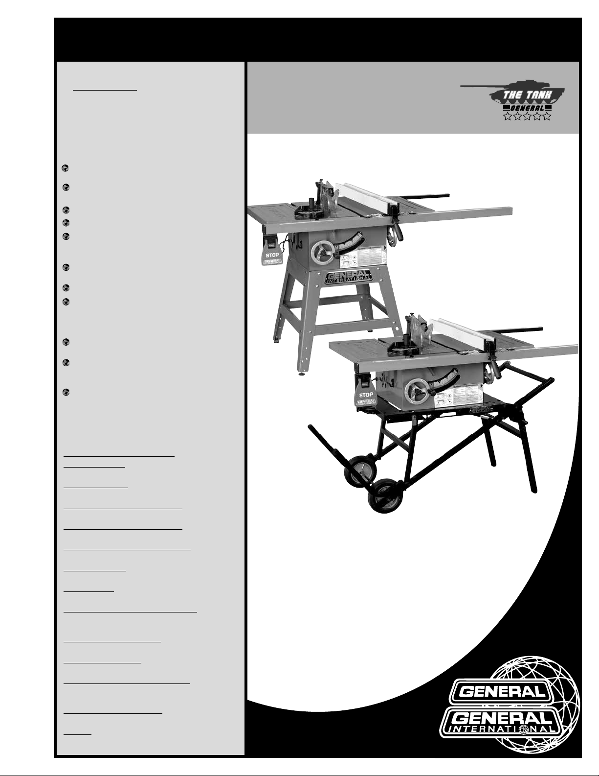
FEATURES
50-090RK: JOB SITE SAW, INCLUDES
50-090R SAW AND FOLDING STAND
#50-095.
50-090RC: CONTRACTOR SAW, INCLUDES
50-090R SAW AND FIXED LEG STEEL STAND
#50-096.
Heavy-duty, precision cast-iron, ribbed table
with miter gauge t-slots.
2 1/2” dust port allows easy connection
to a dust collection system.
Deluxe, quick adjusting miter gauge.
Ruggedly built saw carriage.
Arbor driven by a two step belt, ensuring
straightness and accuracy when the blade
is tilted.
Heavy-duty folding stand with wheels for
easy mobility and storage (50-090RK M1).
Sturdy open base steel stand
Combination riving style splitter and see
through blade guard with anti-kickback
pawls, and a second European style riving
knife also included.
Includes new Excalibur aluminum T-fence
style precision rip fence system.
Smooth running belt driven 2 HP induction
motor for quiet start-up and operation, and
longer running life.
Large paddle-style stop switch.
(50-090RC M1)
10” JOB SITE SAW /
CONTRACTOR SAW
- Left tilt with riving knife
.
50-090RC
SPECIFICATIONS
BLADE DIAMETER
10’’ (254 mm)
ARBOR DIAMETER
5
⁄
” (16 mm)
8
MAXIMUM DEPTH OF CUT AT 90°
1
⁄
3
” (83 mm)
4
MAXIMUM DEPTH OF CUT AT 45°
5
⁄
2
’’ (59 mm)
16
MAXIMUM RIP TO RIGHT OF BLADE
36’’ (914 mm)
DADO CAPACITY
3
⁄
” (19 mm)
4
ARBOR SPEED
3450 RPM
TABLE SIZE (W/O EXTENSION WINGS)
20’’ x 25
EXTENSION WINGS SIZE (2)
10” x 25
DUST PORT DIAMETER
2
OVERALL DIMENSIONS (L X W X H)
69” x 38” x 42
66
MOTOR (PRE-WIRED 110 V)
2 HP, 110 / 220 V, 11.5/5.7A
WEIGHT
233 LBS (106 kg)
217 LBS (98.5 kg)
1
⁄
” (64 mm)
2
1
⁄
” x 38” x 43
2
1
⁄
” (508 x 641 mm)
4
1
⁄
” (254 x 641 mm)
4
1
⁄
” (1745 x 965 x 1080 mm) - 50-090RK
2
1
⁄
” (1690 x 965 x 1150 mm) - 50-090RC
2
- 50-090RK
- 50-090RC
50-090RK
MODEL
#50-090RK M1
#50-090RC M1
VERSION 1_REVISION 3- March 2016 (54014714)
© Copyright General® International
Page 2

GENERAL® INTERNATIONAL
8360 Champ-d’Eau, Montreal (Quebec) Canada H1P 1Y3
Telephone (514) 326-1161 • Fax (514) 326-5555 • www.general.ca
THANK YOU for choosing this General International model 50-090R table saw.
This saw has been carefully tested and inspected before shipment and if properly used and
maintained, will provide you with years of reliable service. To ensure optimum performance
and trouble-free operation, and to get the most from your investment, please take the time to
read this manual before assembling, installing and operating the unit.
The manual’s purpose is to familiarize you with the safe operation, basic function, and features
of this saw as well as the set-up, maintenance and identification of its parts and components.
This manual is not intended as a substitute for formal woodworking instruction, nor to offer the
user instruction in the craft of woodworking. If you are not sure about the safety of performing
a certain operation or procedure, do not proceed until you can confirm, from knowledgeable
and qualified sources, that it is safe to do so.
Once you’ve read through these instructions, keep this manual handy for future reference.
GENERAL ® INTERNATIONAL WARRANTY
All component parts of General® International machinery are carefully tested and inspected during all stages of
production, and each machine is thoroughly inspected upon completion of assembly. Because of our commitment to quality and customer satisfaction, General® International agrees to repair or replace, within a period of
24 months from date of purchase, any genuine part or parts which, upon examination, prove to be defective in
workmanship or material. In order to obtain this warranty, all defective parts must be returned freight pre-paid to
General® International Mfg. Co., Ltd. Repairs attempted without our written authorization will void this warranty.
Disclaimer: The information and specifications in this manual pertain
to the unit as it was supplied from the factory at the time of printing.
Because we are committed to making constant improvements, General
International reserves the right to make changes to components, parts
or features of this unit as deemed necessary, without prior notice and
without obligation to install any such changes on previously delivered
units. Reasonable care is taken at the factory to ensure that the specifications and information in this manual corresponds with that of the
unit with which it was supplied. However, special orders and “after fac-
tory” modifications may render some or all information in this manual
inapplicable to your machine. Further, as several generations of this
model of saw and several versions of this manual may be in circulation, if you own an earlier or later version of this unit, this manual may
not depict your machine exactly. If you have any doubts or questions
contact your retailer or our support line with the model and serial
number of your unit for clarification.
Page 3

GENERAL® INTERNATIONAL WARRANTY
All component parts of General® International and Excalibur by General International®
products are carefully inspected during all stages of production and each unit is thoroughly
inspected upon completion of assembly.
Limited Lifetime Warranty
Because of our commitment to quality and customer satisfaction, General® International
agrees to repair or replace any part or component which upon examination, proves to be
defective in either workmanship or material to the original purchaser for the life of the tool.
However, the Limited Lifetime Warranty does not cover any product used for professional or
commercial production purposes nor for industrial or educational applications. Such cases
are covered by our Standard 2-year Limited Warranty only. The Limited Lifetime Warranty is
also subject to the “Conditions and Exceptions” as listed below.
Standard 2-Year Limited Warranty
All products not covered by our lifetime warranty including products used in commercial,
industrial and educational applications are warranted for a period of 2 years (24 months)
from the date of purchase. General® International agrees to repair or replace any part or
component which upon examination, proves to be defective in either workmanship or material to the original purchaser during this 2-year warranty period, subject to the “conditions and
exceptions” as listed below.
To file a Claim
To file a claim under our Standard 2-year Limited Warranty or under our Limited Lifetime
Warranty, all defective parts, components or machinery must be returned freight or postage
prepaid to General® International, or to a nearby distributor, repair center or other location
designated by General® International. For further details call our service department at 1-888949-1161 or your local distributor for assistance when filing your claim.
Along with the return of the product being claimed for warranty, a copy of the original proof
of purchase and a “letter of claim” must be included (a warranty claim form can also be used
and can be obtained, upon request, from General® International or an authorized distributor)
clearly stating the model and serial number of the unit (if applicable) and including an explanation of the complaint or presumed defect in material or workmanship.
CONDITIONS AND EXCEPTIONS:
This coverage is extended to the original purchaser only. Prior warranty registration is not
required but documented proof of purchase i.e. a copy of original sales invoice or receipt
showing the date and location of the purchase as well as the purchase price paid, must be
provided at the time of claim.
Warranty does not include failures, breakage or defects deemed after inspection by
General® International to have been directly or indirectly caused by or resulting from; improper use, or lack of or improper maintenance, misuse or abuse, negligence, accidents, damage
in handling or transport, or normal wear and tear of any generally considered consumable
parts or components.
Repairs made without the written consent of General® International will void all warranty.
Page 4

TABLE OF CONTENTS
SAFETY RULES ................................................................................................................................... 5
ELECTRICAL REQUIREMENTS ............................................................................................................. 6
Grounding instructions ......................................................................................................................................6
Circuit capacity .................................................................................................................................................6
Converting the motor to 220V ..........................................................................................................................6
Extension cords ..................................................................................................................................................6
IDENTIFICATION OF MAIN PARTS AND COMPONENTS .................................................................... 7
UNPACKING & SET UP ..................................................................................................................... 8
Unpacking ..........................................................................................................................................................8
List of contents ....................................................................................................................................................8
Additional requirements for set up ..................................................................................................................8
PLACEMENT WITHIN THE SHOP / ESTABLISHING A SAFETY ZONE .................................................... 9
CLEAN UP ........................................................................................................................................ 9
ASSEMBLY INSTRUCTIONS ............................................................................................................. 10
Assemble the folding stand (#50-095) ..........................................................................................................10
Assemble the fixed leg stand (#50-096)........................................................................................................11
Assemble the saw ............................................................................................................................................12
Assemble the front fence rails ........................................................................................................................13
Assemble the rear fence rails ........................................................................................................................14
Mount the switch ..............................................................................................................................................14
Install / remove a saw blade .........................................................................................................................15
Adjusting the bevel angle pointer ................................................................................................................15
Selecting, install and adjusting riving knife .................................................................................................15
Select a riving knife .........................................................................................................................................15
Removal/installation .......................................................................................................................................16
Centering the splitter / riving knife on the blade ........................................................................................16
Remove / install the blade cover .................................................................................................................16
Remove .............................................................................................................................................................16
Install ..................................................................................................................................................................17
Remove / install the anti-kickback pawls ....................................................................................................17
Level the table insert .......................................................................................................................................17
Align and level the rip fence .........................................................................................................................18
Align the rip fence parallel to the blade .....................................................................................................18
Align the rip fence 90º to the table ...............................................................................................................18
Level the fence .................................................................................................................................................18
Adjust & align rip fence pointer .....................................................................................................................19
Connecting to a dust collector .....................................................................................................................19
BASIC ADJUSTMENTS AND CONTROLS .......................................................................................... 19
Connecting to a power source .....................................................................................................................19
Adjusting the blade tilt ....................................................................................................................................20
ON/OFF switch and safety pin & padlock ...................................................................................................20
OPERATING INSTRUCTIONS ........................................................................................................... 20
Ripping ..............................................................................................................................................................20
Bevel ripping ....................................................................................................................................................21
Ripping small work pieces .............................................................................................................................21
Cross cutting .....................................................................................................................................................21
Align-a-cut .........................................................................................................................................................21
Bevel cross cutting ...........................................................................................................................................22
Adjusting and using the miter gauge ...........................................................................................................22
Adding an auxiliary fence to the miter gauge ...........................................................................................22
Miter cuts ...........................................................................................................................................................23
Compound mitering .......................................................................................................................................23
Using a dado head blade .............................................................................................................................23
Instructions for folding & unfolding the stand (#50-095) .............................................................................24
RECOMMENDED OPTIONAL ACCESSORIES .................................................................................... 24
PARTS LIST AND DIAGRAMS .................................................................................................. 25 - 35
CONTACT INFORMATION............................................................................................................... 36
Page 5

RULES FOR SAFE OPERATION
To help ensure safe operation, please take a moment to learn the machine’s applications and limitations, as well as potential hazards. General® International disclaims any real or implied warranty and holds itself harmless for any injury that
may result from improper use of its equipment.
1. Do not operate the saw when tired, distracted, or
under the effects of drugs, alcohol or any medica tion that impairs reflexes or alertness.
2. The working area should be well lit, clean and free
of debris.
3. Keep children and visitors at a safe distance when
the saw is in operation; do not permit them to
operate the saw.
4. Childproof and tamper proof your shop and all
machinery with locks, master electrical switches
and switch keys, to prevent unauthorized or unsu pervised use.
5. Stay alert! Give your work your undivided atten tion. Even a momentary distraction can lead to seri ous injury.
6. Fine particulate dust is a carcinogen that can be
hazardous to health. Work in a well-ventilated area
and whenever possible use a dust collector and
wear eye, ear and respiratory protection devices.
7. Do not wear loose clothing, gloves, bracelets, neck laces or other jewelry while the saw is in operation.
Wear protective hair covering to contain long hair
and wear non-slip footwear.
8. Be sure that adjusting wren ches, tools, drinks and
other clutter are removed from the machine and/or
the table surface before operating.
9. Keep hands well away from the blade and all mo ving parts. Use a brush, not hands, to clear away
chips and dust.
10. Be sure that the blade is securely installed and in
proper cutting direction before operation.
11. Be sure the blade has gained full operating speed
before beginning to cut.
12. Always use a clean, properly sharpened blade.
Dirty or dull blades are unsafe and can lead to
accidents.
13. If using a power feeder, stop the feeder before stop ping the table saw.
14. Do not push or force stock into the blade. The saw
will perform better and more safely when working
at the rate for which it was designed.
15. Use suitable support when cutting stock that does
not have a flat surface. Always hold stock firmly
against the fence when ripping, or against the miter
gauge when cross-cutting.
16. To minimize risk of injury in the event of workpiece
kickback, never stand directly in-line with the blade
or in the potential kickback path of the work piece.
18. Keep blade guards in place and in working order.
If a guard must be removed for maintenance or
cleaning, be sure it is properly reattached before
using the tool again.
19. Never leave the machine running with the power
on when not in operation.
20. Use of parts and accessories NOT recommended
by
ment malfunction or risk of injury.
21. Never stand on machinery. Serious injury could
result if the tool is tipped over or if the blade is unin tentionally contacted.
22. Always disconnect tool from power before servicing
or changing accessories such as blades, or before
performing any maintenance, cleaning or adjust ments, or if the machine will be left unattended.
23. Make sure that switch is in «OFF» position before
plugging in the power cord.
24. Make sure the tool is properly grounded. If equip ped with a 3-prong plug it should be used with a
three-pole receptacle. Never remove the third
prong.
25. Do not use this saw for other than its intended use. If
used for other purposes,
disclaims any real implied warranty and holds itself
harmless for any injury, which may result from that
use.
26. Don’t use in dangerous environment. Don’t use
power tools in damp or wet locations, or expose
them to rain. Keep work area well lighted.
27. Always use safety glasses. Also use face or dust
mask if cutting operation is dusty. Everyday eye
glasses only have impact resistant lenses, they are
not safety glasses.
28. Use clamps or a vise to hold work when practical.
It’s safer than using your hand and it frees both
hands to operate tool.
29. Check damaged parts. Before further use of the
tool, a guard or other part that is damaged should
be carefully checked to determine that it will oper ate properly and perform its intended function -
check for alignment of moving parts, breakage of
parts, mounting, and any other conditions that may
affect its operation. A guard or other part that is
damaged should be properly repaired or
replaced.
30. Direction of feed. Feed work into blade against the
direction of rotation of the blade.
GENERAL® INTERNATIONAL
GENERAL® INTERNATIONAL
may result in equip-
17. Avoid working from awkward or off balance posi tions. Do not overreach while cutting; keep both
feet on floor. Never lean over or reach over the
blade and never pull the work piece over the blade
from behind. Use out feed support or have an assis tant help when ripping long material.
5
Page 6
ELECTRICAL REQUIREMENTS
BEFORE CONNECTING THE MACHINE TO THE POWER SOURCE, VERIFY THAT THE VOLTAGE OF YOUR POWER SUPPLY CORRESPONDS WITH THE VOLTAGE SPECIFIED ON THE MOTOR I.D. NAMEPLATE. A POWER SOURCE WITH GREATER VOLTAGE THAN
NEEDED CAN RESULT IN SERIOUS INJURY TO THE USER AS WELL AS DAMAGE TO THE MACHINE. IF IN DOUBT, CONTACT A
QUALIFIED ELECTRICIAN BEFORE CONNECTING TO THE POWER SOURCE.
THIS TOOL IS FOR INDOOR USE ONLY. DO NOT EXPOSE TO RAIN OR USE IN WET OR DAMP LOCATIONS.
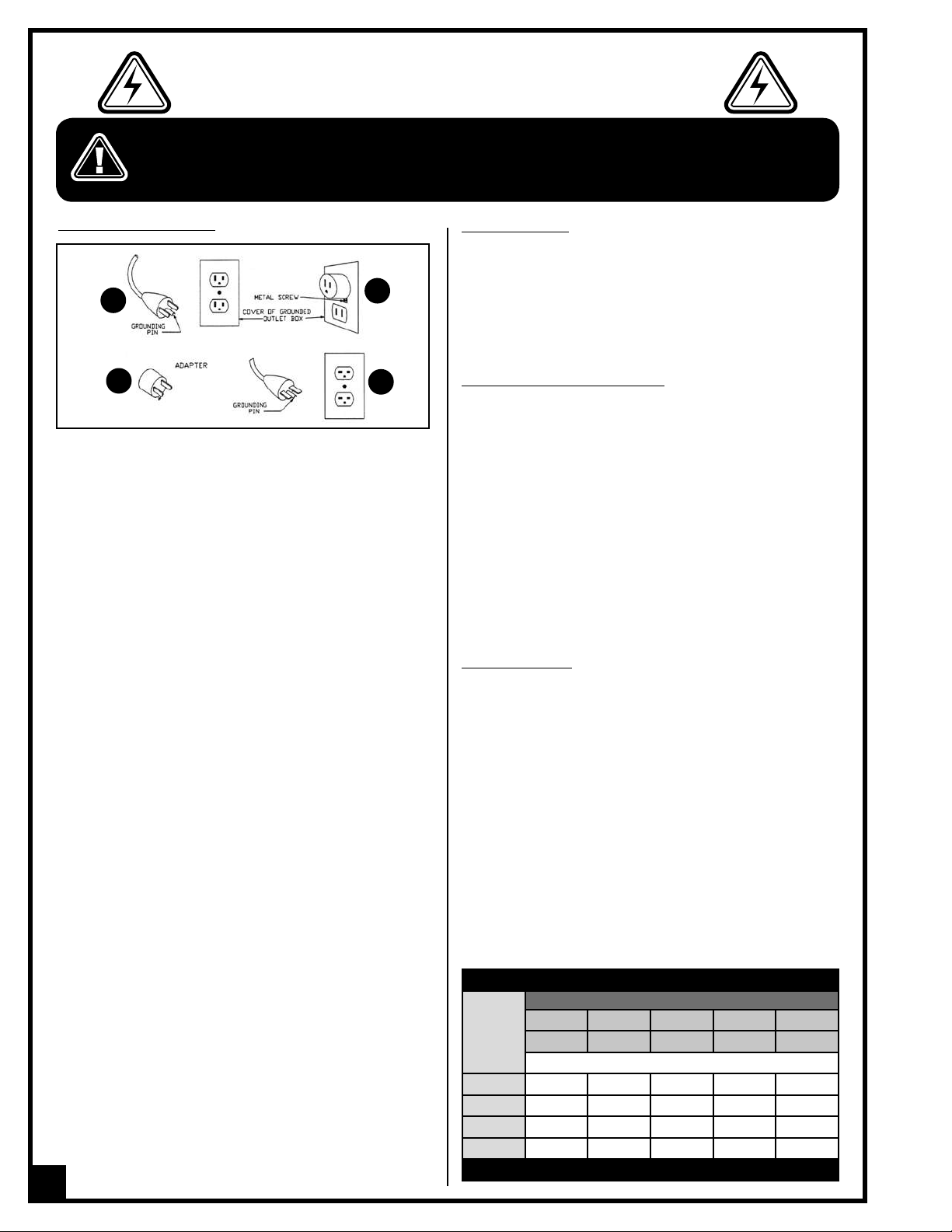
GROUNDING INSTRUCTIONS
A
C
In the event of a malfunction or breakdown, grounding provides a path of least resistance for electric current to reduce
the risk of electric shock. This tool is equipped with an electric
cord having an equipment-grounding conductor and a
grounding plug. The plug must be plugged into a matching
outlet that is properly installed and grounded in accordance
with all local codes and ordinances.
Do not modify the plug provided - if it will not fit the outlet;
have the proper outlet installed by a qualified electrician.
Improper connection of the equipment-grounding conductor can result in a risk of electric shock. The conductor
with insulation having an outer surface that is green with or
without yellow stripes is the equipment-grounding conductor.
If repair or replacement of the electric cord or plug is necessary, do not connect the equipment-grounding conductor to
a live terminal.
Check with a qualified electrician or service personnel if the
grounding instructions are not completely understood, or if in
doubt as to whether the tool is properly grounded.
Use only three prong grounding plugs and receptacles that
accept that type of plug. Repair or replace damaged or
worn cord immediately.
This tool is intended for use on a circuit that has an outlet
that looks like the one illustrated in Sketch A. The tool has a
grounding plug that looks like the plug illustrated in Sketch A.
A temporary adapter, which looks like the adapter illustrated
in Sketches B and C, may be used to connect this plug to
a two pole receptacle as shown in Sketch B if a properly
grounded outlet is not available. The temporary adapter
should be used only if a properly grounded outlet has been
installed by a qualified electrician - this adapter is not permitted in Canada.
This tool is intended for use on a circuit that has an outlet
that looks like the one illustrated in Sketch D. The tool has a
grounding plug that looks like the plug illustrated in Sketch
D. Make sure the tool is connected to an outlet having the
same configuration as the plug. No adapter is available or
should be used with this tool. If the tool must be reconnected
for use on a different type of electric circuit, the reconnection
should be made by qualified service personnel; and after
reconnection, the tool should comply with all local codes
and ordinances.
B
D
6
CIRCUIT CAPACITY
Make sure that the wires in your circuit are capable of handling the amperage draw from your machine, as well as any
other machines that could be operating on the same circuit.
If you are unsure, consult a qualified electrician. If the circuit
breaker trips or the fuse blows regularly, your machine may
be operating on a circuit that is close to its amperage draw
capacity. However, if an unusual amperage draw does not
exist and a power failure still occurs, contact a qualified technician or our service department.
CONVERTING THE MOTOR TO 220V
Note: When converting motor voltage on a machine that
is equipped with a magnetic switch, the switch contactor
must also be changed out for one made for the appropriate
voltage, as well as the thermal relay/circuit breaker and
“power in” indicator light (if applicable). Failure to make
these necessary modifications to the switch will lead to
malfunction and permanent switch failure.
Should you need to convert your machine’s motor from 110V
to 220V power, there is an electrical schematic drawing on
the inside of the motor cover plate. Unless you are a qualified
electrician, we do not recommend attempting this conversion
on your own. If you choose to do so, you may risk serious personal injury, damage to the motor and voiding the warranty
of your machine.
We suggest you ask your local General International distributor
to recommend qualified electricians in your area (or perhaps
one of their own technicians) who can make this conversion
properly and safely.
EXTENSION CORDS
If you find it necessary to use an extension cord with your
machine, use only 3-wire extension cords that have 3-prong
grounding plug and a matching 3-pole receptacle that
accepts the tool’s plug. Repair or replace a damaged extension cord or plug immediately.
Make sure the cord rating is suitable for the amperage listed
on the motor I.D. plate. An undersized cord will cause a drop
in line voltage resulting in loss of power and overheating. The
accompanying chart shows the correct size extension cord
to be used based on cord length and motor I.D. plate amp
rating. If in doubt, use the next heavier gauge. The smaller the
number, the heavier the gauge.
Use proper extension cord. Make sure your extension cord is in
good condition. When using an extension cord, be sure to use
one heavy enough to carry the current your product will draw.
An undersized cord will cause a drop in line voltage resulting
in loss of power and overheating. Table 1 shows the correct
size to use depending on cord length and nameplate ampere
rating. If in doubt, use the next heavier gage. The smaller the
gage number, the heavier the cord.
TABLE - MINIMUM GAUGE FOR CORD
TOTAL LENGTH OF CORD IN FEET
AMPERE
RATING
6 TO 10
10 TO 12
12 TO 16
* NR = Not Recommended
110 VOLTS 25 FEET 50 FEET 100 FEET 150 FEET
220 VOLTS 50 FEET 100 FEET 200 FEET 300 FEET
AWG
< 5
------->
------->
------->
------->
18 16 16 14
18 16 14 12
16 16 14 12
14 12 * NR * NR
Page 7
10” JOB SITE SAW / CONTRATOR SAW
50-090RK M1 or 50-090RC M1 (left tilt with riving knife)
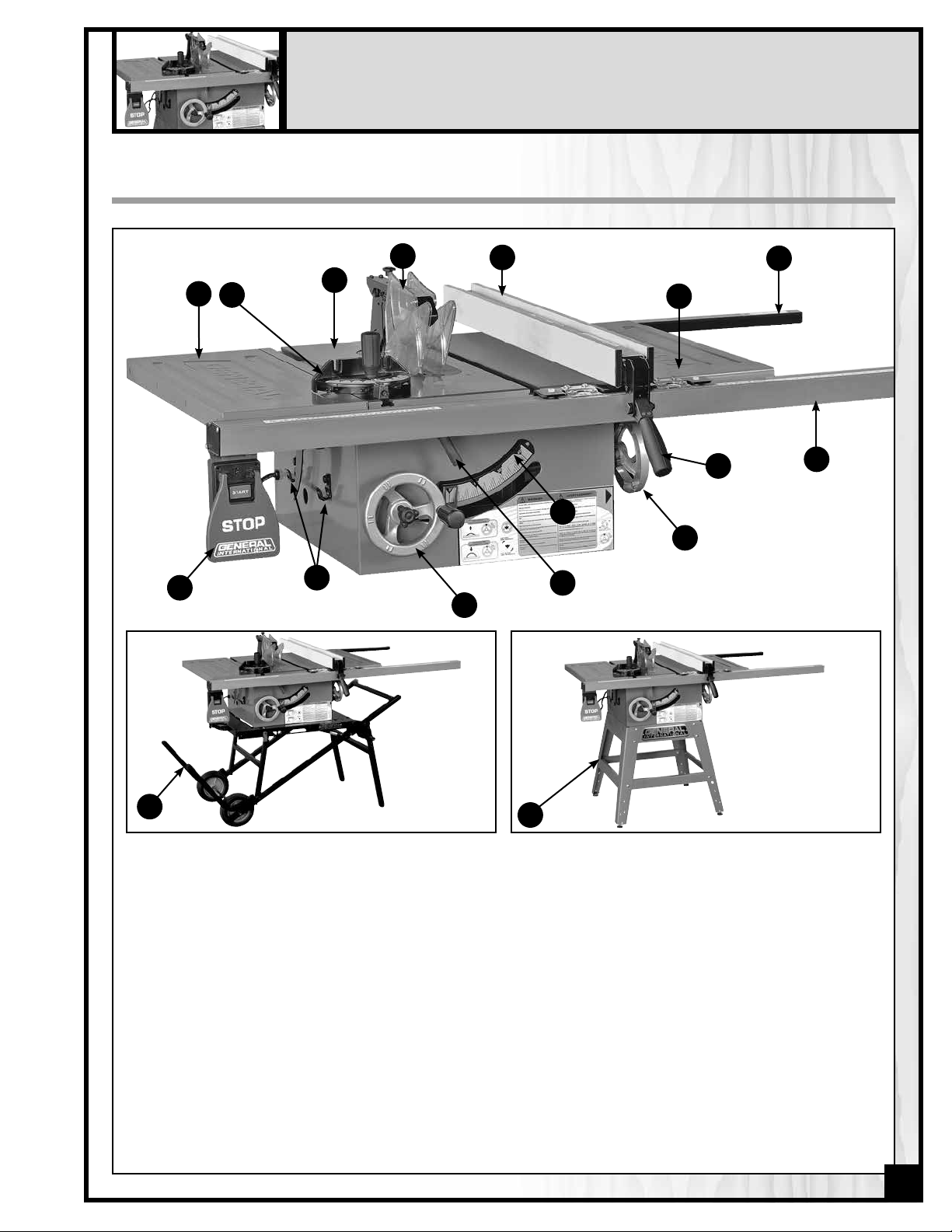
IDENTIFICATION OF MAIN PARTS AND COMPONENTS
D
A
B
N
C
M
E
F
I
K
J
Q
L
G
H
O
A- LEFT TABLE
EXTENSION
B- MITER GAUGE
C- MAIN TABLE
D- BLADE GUARD AND
SPLITTER ASSEMBLY
E- RIP FENCE
F- RIGHT TABLE EXTENSION
50-090RK M1
G- REAR RAIL
H- FRONT RAIL
I- RIP FENCE LOCKING
HANDLE
J- BLADE TILT ADJUSTMENT
HANDWHEEL
K- BEVEL SCALE
L- BLADE HEIGHT
ADJUSTMENT HANDWHEEL
P
50-090RC M1
M- MITER GAUGE STORAGE
BRACKET
N- ON/OFF SWITCH
O- FOLDING STAND (50-090RK)
P- FIXED LEG STAND (50-090RC)
Q- BLADE TILT LOCK LEVER
7
Page 8
UNPACKING & SET UP
UNPACKING
Carefully unpack and remove the unit and its components from its shipping containers and check for missing or
damaged items as per the list contents below.
Note: Please report any damaged or missing items to your General International distributor immediately.
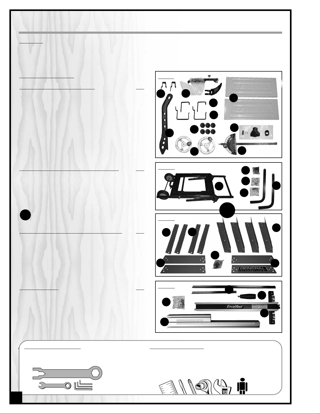
LIST OF CONTENTS
BOX #1 - SAW & COMPONENTS: Qty
A - MITER GAUGE STORAGE HOOK .................................. 2
B - TOOL STORAGE HOOK ............................................... 2
C - FENCE STORAGE HOOK .............................................. 2
D - BLADE GUARD & RIVING KNIFE .................................. 1
E - TABLE EXTENSIONS ....................................................... 2
F - PUSH STICK ................................................................... 1
G - FLANGE HEAD BOLT ..................................................... 6
H - HARDWARE BAG .......................................................... 1
I - HANDWHEELS ............................................................... 2
J - MITER GAUGE ............................................................. 1
BOX #2 - FOLDING STAND (50-090RK M1): Qty
A - PARTIALLY ASSEMBLED FOLDING STAND.................... 1
B - VERTICAL SUPPORT LEGS ............................................ 2
C - SUPPORT LEG MOUNTING HARDWARE ...................... 1
D - PISTON MOUNTING HARDWARE ................................. 1
E - SAW TO STAND MOUNTING HARDWARE ................... 1
OR
BOX #2 - FIXED LEG STAND (50-090RC M1): Qty
A - STAND LEG ................................................................... 4
B - TOP CROSS BRACE
C - TOP CROSS BRACE
D - BOTTOM CROSS BRACE
E - BOTTOM CROSS BRACE
F - HARDWARE BAG .......................................................... 1
(FRONT & BACK) ............................... 2
(SIDE) ............................................. 2
(FRONT & BACK) . . . . . . . . . . . . . .2
(SIDE) ..................................... 2
BOX #1
A
F
BOX #2
BOX #2
D
C
D
E
B
C
G
I
H
J
E
D
A
B
C
OR
A
E
F
B
BOX #3 - FENCE: Qty
A - REAR FENCE RAILS ....................................................... 2
B - FENCE LOCK HANDLE ................................................ 1
C - HARDWARE BAG .......................................................... 1
D - FENCE BODY ................................................................ 1
E - FRONT FENCE RAILS ..................................................... 2
ASSEMBLY TOOLS PROVIDED
• 2 Arbor blade guard bracket wrenches
• 11-13 mm combination wrench
• 3 Allen wrenches
8
BOX #3
A
B
C
D
E
ADDITIONAL TOOLS NEEDED
• Straightedge
• Large slot & large Phillips screwdrivers
• Socket wrench kit (recommended) & adjustable wrench
• An extra person for help with lifting
Page 9
PLACEMENT WITHIN THE SHOP /
ESTABLISHING A SAFETY ZONE
THIS MODEL IS HEAVY. DO NOT OVER-EXERT.
A HOIST OR FORKLIFT WITH STRAPS SHOULD
BE USED TO LIFT THIS MACHINE.
TO LIMIT THE RISK OF SERIOUS INJURY
OR DAMAGE TO THE MACHINE, ANY
EQUIPMENT USED TO LIFT THIS MACHINE
SHOULD HAVE A RATED CAPACITY IN EXCESS OF 233 LBS
(106 KG) FOR 50-090RK & 217 LBS (98.5 KG) FOR
50-090RC.
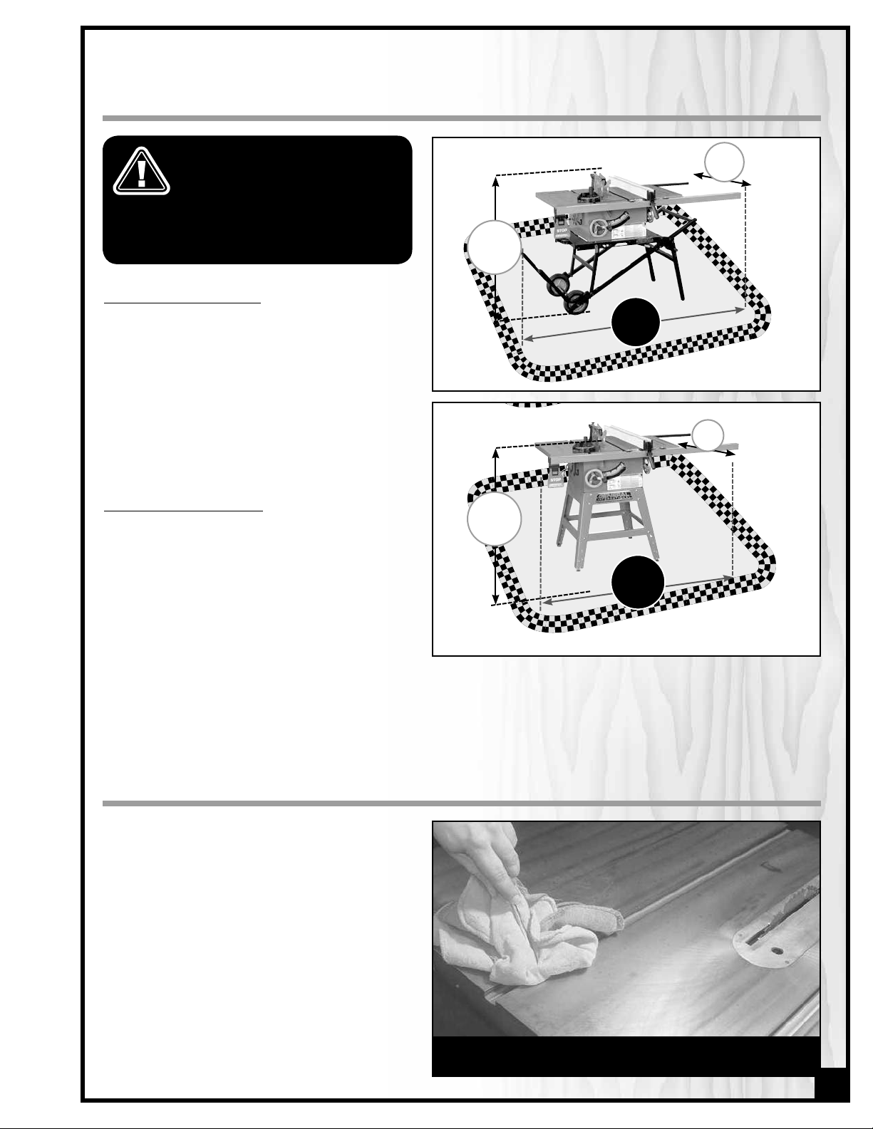
PLACEMENT WITHIN THE SHOP
This machine should be installed and operated
only on a solid, flat and stable floor that is able
to support the weight of the saw and the ope-rator.
Using the dimensions shown as a guideline,
plan for placement within your shop that will
allow the operator to work unencumbered and
unobstructed by foot traffic (either passing shop
visitors or other shop workers) or other tools or
ma-chinery.
ESTABLISHING A SAFETY ZONE
For shops with frequent visitors or multiple operators, it is advisable to establish a safety zone
around shop machinery. A clearly defined “nogo” zone on the floor around each machine
can help avoid accidents that could cause
injury to either the operator or the shop visitor.
It is advisable to take a few moments to either
paint (using non-slip paint) or using tape, define
on the floor the limits or perimeter of each
machines safety zone. Take steps to ensure that
all operators and shop visitors are aware that these areas are off limits whenever a machine is running for everyone but the individual operating the unit.
50-090RK M1
42 ½”
50-090RC M1
43 ½”
38”
69”
38”
66 ½”
CLEAN UP
The protective coating on the saw table prevents
rust from forming during shipping and storage.
Remove it by rubbing with a rag dipped in kerosene, mineral spirits or paint thinner. (Dispose
of potentially flammable solvent-soaked rags
according to manufacturer’s safety recommendations.)
A putty knife, held flat to avoid scratching the
surface, may also be used to scrape off the
coating followed by clean-up with solvent. Avoid
rubbing the saw’s painted surfaces, as many solvent-based products will remove paint.
To prevent rust, apply a light coating of paste wax
or use regular applications of any after-market
surface protectant or rust inhibitor.
Tip: With a screw driver, push a solvent-saturated rag into the
T-slots to remove the grease.
9
Page 10
ASSEMBLY INSTRUCTIONS
SERIOUS PERSONAL INJURY COULD OCCUR IF YOU CONNECT THE MACHINE TO THE POWER SOURCE BEFORE YOU HAVE
COMPLETED THE INSTALLATION AND ASSEMBLY STEPS. DO NOT CONNECT THE MACHINE TO THE POWER SOURCE UNTIL
INSTRUCTED TO DO SO.
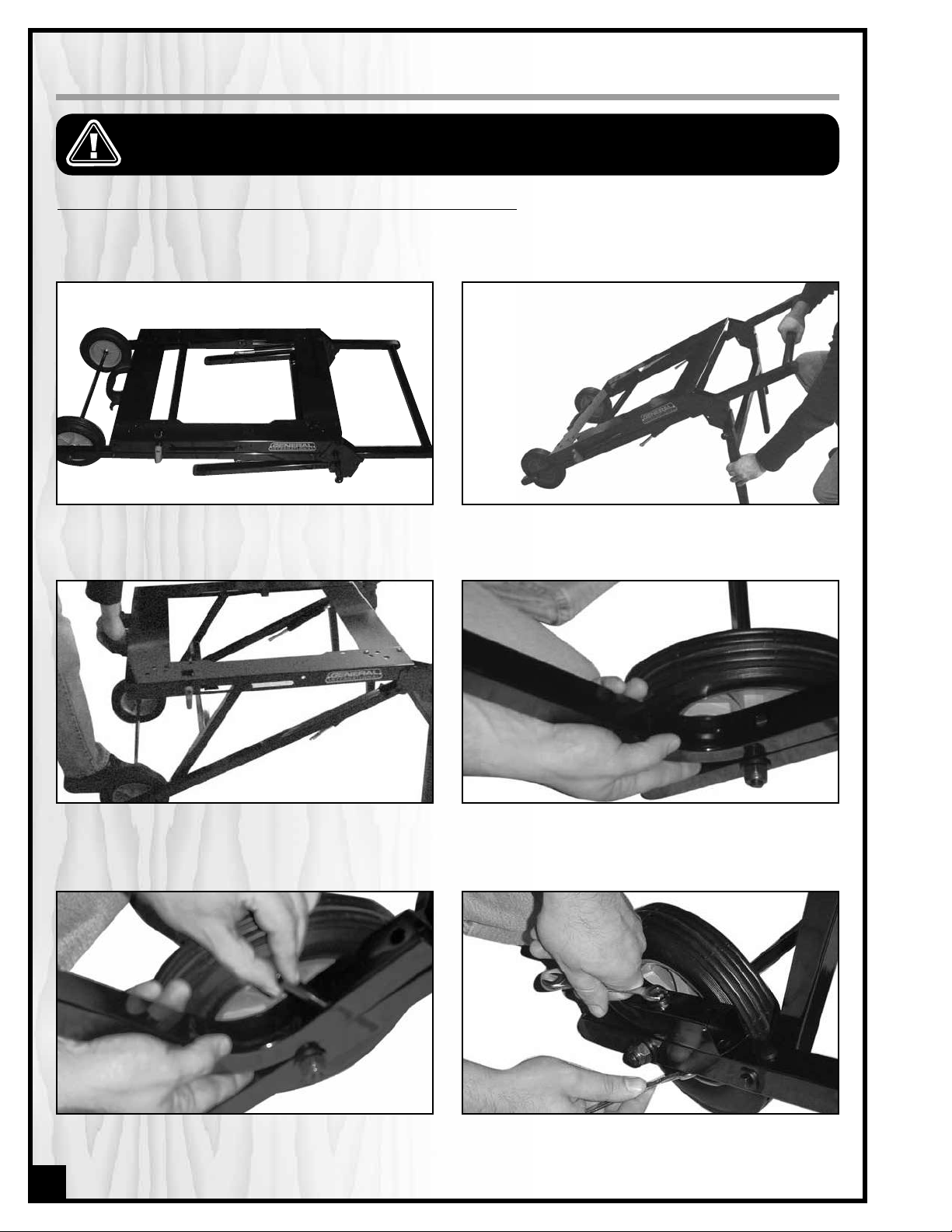
ASSEMBLE THE FOLDING STAND (50-095 SUPPLIED WITH 50-090RK M1 ONLY)
The folding stand comes partially assembled. To complete the stand assembly follow the steps listed below. (Please
note that if you purchased this saw as a special order version 50-090R M1 or 50-090RC, then the folding stand is not included - please skip ahead to the next section “Assemble the Saw”).
1. Lay the stand flat on the ground as shown. 2. Raise the handle off the ground and lower the sup-
3. Raise the front handle until the front support bra-
cket click and locks into place.
port legs as shown.
4. Attach the 2 vertical support legs as shown above.
Hold the leg onto the frame of the stand lining up
the 2 holes in the leg with the corresponding holes
in the stand.
5. Fit a spacer/bushing into the hole. 6. Using a 10 mm socket and 10 mm or adjustable
10
wrench, secure each leg using a bolt, 2 washers
and a nut (supplied) for each of the 2 holes per
leg.
Page 11
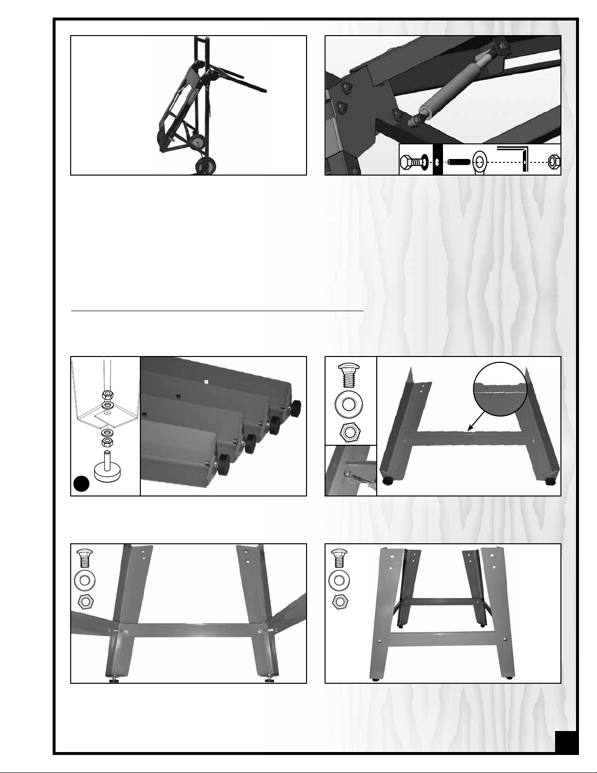
7. To access the 2 pistons tilt the stand forward onto its
vertical support legs as shown.
8. Using a 1/2” socket and 1/2” or adjustable wrench
secure the 2 pistons to the stand frame using the
bolt, washer, spacer & nut in the sequence shown.
ASSEMBLE THE FIXED LEG STAND (50-096 SUPPLIED WITH 50-090RC M1 ONLY)
To assemble the fixed leg stand assembly follow the steps listed below. (Please note that if you purchased this saw
as a special order version 50-090R M1 or 50-090RK M1, then the fixed leg stand is not included - please skip ahead to the
next section “Assemble the Saw”).
Side
cross brace
A
1. Attach a levelling foot to each leg using 2 hex nuts
and 2 flat washers per leg, in the assembly order
shown above A.
3. Attach the front and rear cross braces to one side
cross brace/leg assembly as shown using 2 car riage bolts, flat washers and hex nuts.
2. Attach one side cross brace to 2 stand legs as
shown using 2 carriage bolts, washers and nuts.
Repeat with the other side cross brace and other
2 legs.
4. Attach the second side cross brace/leg assembly
to the front and rear cross braces as shown using
2 carriage bolts, flat washers and hex nuts.
11
Page 12

5. Attach the front and rear top shelves as shown
using 4 carriage bolts, flat washers and hex nuts for
each cross brace.
ASSEMBLE THE SAW
With the help of an assistant lift the saw onto the stand (or
your own stand if the unit was special ordered without the
stock stand).
Using a 13 mm wrench & socket, secure the saw to the
stand with the supplied bolts, nuts and washers in the
order shown.
THIS TABLE SAW IS HEAVY. SEEK ASSISTANCE WHEN LIFTING IT ONTO THE STAND.
6. Attach the two side top shelves as shown using
4 carriage bolts, flat washers and hex nuts for each
cross brace.
Install the fence storage brackets to the saw as shown. Install the miter gauge storage brackets to the saw as
Install the blade height adjustment hand wheel as
shown.
shown.
Install the blade tilting hand wheel as shown.
12
Page 13

Attach the steel table extension wings to the main table
as shown using 8 12mm hex head bolts (4 per wing) and
8 lock washers. Align the table extensions with the table
and loosely attach the bolts. Place a straight edge on
the table and extension as shown to align the extension
table and then tighten down the bolts.
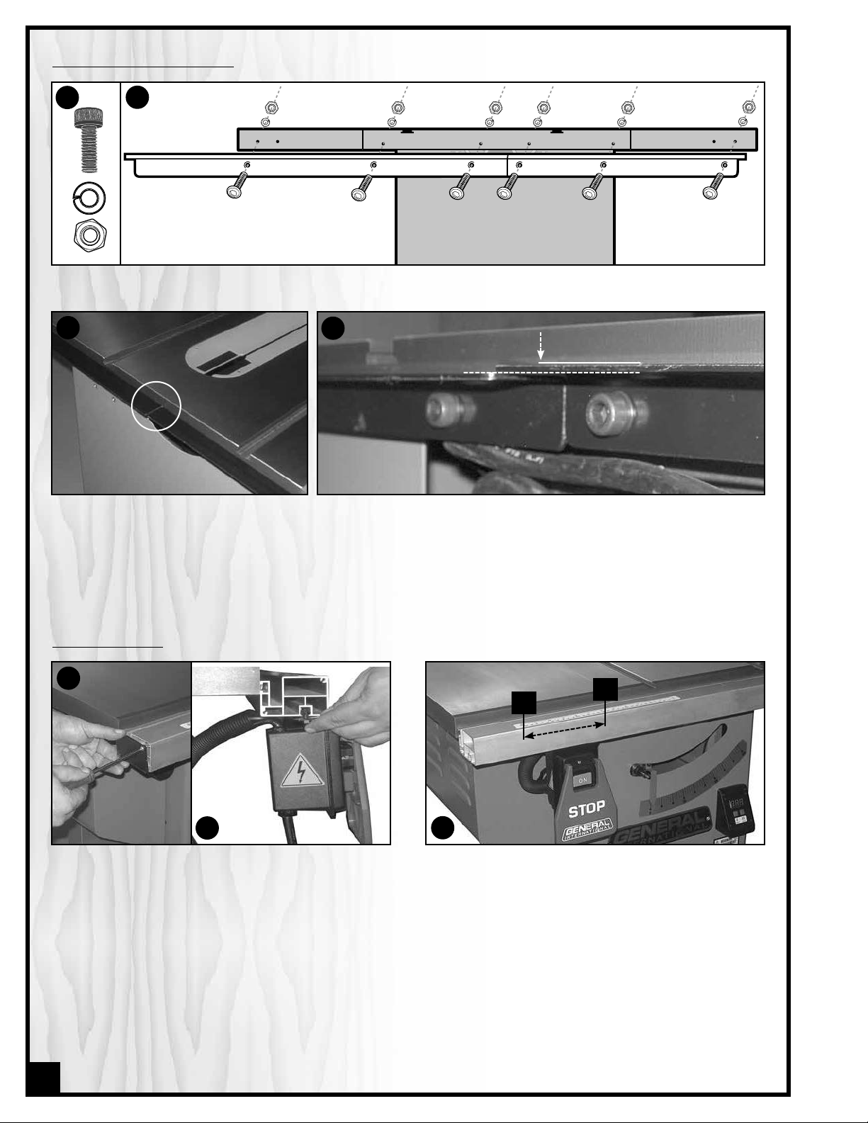
ASSEMBLE THE FRONT FENCE RAILS
level here
flush here
B
TABLE
A
Loosely thread the six square head bolts to the front of the table as shown in A. Assemble the fasteners in the
1.
order shown in B.
Do not tighten down the nuts; leave the square heads of the bolt protruding from the table as shown in C.
2.
FLUSH HERE
D
3. From the left side of the saw, slide the upper slot D
of the left (shorter) front rail onto the square head
bolts E.
E
4. Set the left end of the rail flush to the outside edge
of the extension wing.
C
F
5. From the right side of the saw, slide the upper slot of
the right front rail onto the square head bolts F.
G
6. Fit the 2 rails together G.
7. Tighten down the nuts to firmly secure the front rails
to the table.
13
Page 14
ASSEMBLE THE REAR FENCE RAILS
A
1. Use 6 cap screws with lock washers and nuts A to assemble the rear rails to the rear of the saw as shown B.
C
B
D
2. Make sure that the intersection C between the two rear rails is leveled D.
MOUNT THE SWITCH
A
B
1. Temporarily remove the end cap from the left end of
the front rail A.
2. Slide the heads of the bolts of the switch mounting
bracket into the t-sot on the underside of the fence
rail B.
C
3. Position the switch somewhere between 4” and 12”
from the end of the fence rail C, depending upon
your personal preference.
4. Tighten the screws to secure the switch in place.
5. Reinstall the end cap on the front rail.
4”
12”
14
Page 15

INSTALL / REMOVE A SAW BLADE
BE SURE THE SAW IS UNPLUGGED AND COMPLETELY DISCONNECTED FROM THE POWER SOURCE
WHENEVER INSTALLING OR REMOVING A SAW
BLADE!
1. Loosen the retaining screw and remove the table
insert plate, A.
2. Install a saw blade (not supplied with the saw) so
that the openings between the teeth face the front of
the saw
3. Replace the flange and arbor nut. Wedge a board
between the saw teeth at the back of the saw, B, so
the blade won’t turn as you tighten the nut clockwise
with the arbor wrench.
Remove a saw blade: wedge a block of wood between
the teeth in front of the saw and turn the arbor wrench
toward you, or counter-clockwise.
NOTE: This saw is intended for use with 10” (250mm) diameter or less
saw blades having a center hole diameter of 5/8”. There are many
types of blades available to perform specific cutting jobs, such as
crosscuts or ripping only, or for use with plywood, panelling and
other products. A good quality specialty blade can produce a finer
finish, be more efficient and place less strain on the saw. Use only
saw blades designed for use at a maximum operating speed of 6000
RPM or less. Saw blades should be kept clean and sharp. Never store
saw blades by stacking them directly in contact with each other.
Place a layer of cardboard or similar material between the blades
to keep them from coming into contact with each other.
(the blade spins in the counter-clockwise direction).
A
B
ADJUSTING THE BEVEL ANGLE POINTER
The bevel pointer should read “0” when the blade is at
90° to the table. If not, loosen the pointer screw, manually
reset the pointer to 0 and re-tighten the screw.
SELECTING, INSTALLING AND ADJUSTING RIVING KNIFE
SELECT A RIVING KNIFE
Two riving knives are provided:
- A combination riving style splitter and blade guard
with anti-kickback pawls A;
- A European style riving knife without blade guard
B.
The riving knife must always be used with a blade guard.
If you already own an independently attached bladeguard such as our Excalibur 50-EXBC10, use the riving
knife B. If you do not already own a blade guard, use the
splitter/blade guard assembly A.
A
B
THE BLADE MUST NEVER REMAIN EXPOSED WHEN USING THE SAW. TO PREVENT THE RISK OF SERIOUS INJURIES, ALWAYS
COVER THE BLADE WITH A BLADE GUARD.
15
Page 16

REMOVAL/INSTALLATION
Set the blade to 90º and raise it to its highest position and
remove the table insert. If already installed, remove the
splitter or riving knife by loosening the lock knob A and
pulling the splitter or riving knife up out of its mounting
bracket.
To install, fit the bottom end of the splitter or riving knife
into the slot in the mounting bracket and tighten the lock
knob to lock it in place. Re-install the table insert.
CENTERING THE SPLITTER / RIVING KNIFE ON THE BLADE
The splitter/riving knife should be more or less centered on
the blade to allow for workpiece clearance on both sides
of the blade A.
1. Place a straightedge against a front and back tooth
of the blade C. There should be a more or less equal
gap between the straightedge and the splitter/riving
knife on both sides of the blade D.
2. The splitter/knife mounting bracket assembly is held
together by two button head locking screws E. Both
90º to the table and parallel/centered to the blade
alignments can be achieved by adjusting the four
set screws F. The locking screws must first be loo sened (using a 3mm allen key) – 1/4 turn or more,
depending upon how much adjustment is re quired, in order to be able to adjust the set screws F
using a 2.5 mm allen key.
THE SPLITTER/RIVING KNIFE SHOULD NEVER PROTRUDE
BEYOND EITHER EDGE OF THE BLADE
TRUCT THE WORKPIECE AND LEAD TO A DANGEROUS
KICKBACK SITUATION WHICH CAN LEAD TO SERIOUS
PERSONAL INJURY.
THIS WILL OBS-
B
.
TOP VIEW
Riving Knife
Blade
Table insert
LEFT SIDE
D
C
RIGHT SIDE
LARGER VIEW
A
D
A
DON’T
B
E
F
REMOVE/INSTALL THE BLADE COVER
REMOVE
A
1. Disconnect the machine from the power source.
2. Loosen the Knob, A, on the top of the cover.
16
2
1
3. Pull back 1 and lift 2 the cover body until it can be
removed from the splitter.
Page 17

INSTALL
A
1. Align the pins on the blade cover with the 2 hooks
A on the splitter.
2. Slip the cover down onto the splitter 1, push it back
into the hooks 2 and then tighten the lock knob B.
REMOVE/INSTALL ANTI-KICKBACK PAWLS
1
2
B
1. Disconnect the machine from the power source.
2. Remove the blade cover.
LEVEL THE TABLE INSERT
Place the insert into the table and use a straightedge to
determine whether the insert is level with the table top A.
Turn each of the 5 adjusting screws B with the supplied
Allen wrench until done.
Suggestion: Start by adjusting one rear screw and its diagonal opposite in front, then tweak the remaining screws.
Note: If the sawblade has already been installed, use the
raising handwheel to lower the blade below the table surface
before leveling the insert.
2
1
3. Press down the pivot block on the anti-kickback
body and turn it up to lift the body.
4. Reserve steps 2 & 3 to re-install the anti-kickback.
A
B
17
Page 18

ALIGN AND LEVEL THE RIP FENCE
THE RIP FENCE MUST BE PARALLEL TO THE BLADE
DU-RING OPERATION. FAILURE TO SET THE RIP FENCE PARALLEL TO THE BLADE CAN RESULT IN KICKBACK AND
POSSIBLE SERIOUS INJURY.
ALIGN THE RIP FENCE PARALLEL TO THE BLADE
To make satisfactory rip cuts, your fence must be aligned
perfectly parallel with the saw blade.
1. Slide the fence over to the right T-slot on your saw ta ble top A. Lock down the fence handle B and make a
visual check that the fence is parallel with the T-slot all
along its length.
Also, you can place a small 3/4” thick block of wood,
upright into the T-slot and slide it from the front to the
back checking its distance from the left edge of the
fence.
2. If the fence is not parallel, it can be adjusted by using
an Allen key to turn one or both of the screws C or
D. Do this slowly, just an eighth to a quarter turn at a
time, or you will quickly overshoot the desired adjust ment.
Note: It is always good practice to periodically recheck
the alignment of your fence to the blade.
A
B
C
D
ALIGN THE RIP FENCE PERPENDICULAR (90°) TO THE TABLE
Place a machinist square on the table against the fence
and look for a gap between the square and the fence
(bottom and top) or the table. If needed, adjust either of
the two plastic set screws E, to tilt the fence slightly and
square it to the table.
LEVEL THE FENCE
The fence should be parallel to the table and sit approximately 2 mm above the table’s surface (so the fence will
not scratch the table and a thin work piece will not get
stuck or jammed under the fence).
To level and adjust the height of the fence:
1. Loosen the hex nut F on the leveling foot G located un der the rear end of the fence.
2. Raise or lower the leveling foot until there is a spa cing of 2 mm (approx.) between the bottom of the fence
and the table, then tighten the hex nut to lock the set ting of the leveling foot.
E
G
LARGER VIEW
F
3. If needed, to level the fence, adjust the plastic set screws E equally, thereby raising or lowering the front of the
fence an equal amount on either side so as not to undo the previous perpendicular adjustment.
18
Page 19

ADJUST & ALIGN RIP FENCE POINTER
STOP
ON
See your F36 T28/52 fence manual for further information.
Set blade to 90° and raise it to the maximum height. Move
the fence till it lightly touches the right side of the blade
and push down the locking lever to lock the fence in place
A.
With the fence locked in place against the blade, loosen
the pointer screws B. Line up the reference line C on the
pointer with the zero point on the tape D and re-tighten the
pointer screws.
Note: When changing blades, re-align the pointer with the zero
points on the tapes to account for thinner or thicker blades.
CONNECTING TO A DUST COLLECTOR
• There is a 2 1/2” dust outlet located on the lower left of
the saw cabinet allowing for the connection to a dust
collection system (not included).
• Be sure to use appropriate size hose and fittings (not
included) and check that all connections are sealed
tightly to minimize airborne dust.
• If you do not already own a dust collection system
consider contacting your General® International dis tributor for information on our complete line of dust col lection systems and accessories or visit our website at
www.general.ca
ALWAYS TURN ON THE DUST COLLECTOR BEFORE
STARTING THE SAW AND ALWAYS STOP THE SAW
BEFORE TURNING OFF THE DUST COLLECTOR.
50-090RK M1
50-090RC M1
A
B
C
D
STOP
STOP
BASIC ADJUSTMENTS & CONTROLS
TO AVOID RISK OF SHOCK OR FIRE DO NOT OPERATE THE UNIT WITH A DAMAGED POWER CORD OR PLUG. REPLACE DAMAGED
CORD OR PLUG IMMEDIATELY.
TO AVOID UNEXPECTED OR UNINTENTIONAL START-UP, MAKE SURE THAT THE POWER SWITCH ON THE SAW IS IN THE OFF POSITION BEFORE CONNECTING TO A POWER SOURCE.
CONNECTING TO A POWER SOURCE
Once the assembly steps have been completed, uncoil
the power cord and plug it into an appropriate outlet.
Refer back to the section entitled “ELECTRICAL REQUIREMENTS” and make sure all requirements and grounding instructions are followed. When cutting operations
have been completed unplug the saw from the power
source.
SWITCH OFF
19
Page 20

ADJUSTING THE BLADE TILT
A
1. Unlock the tilt mechanism by turning the lock lever
A counterclockwise, then adjust the blade tilt as per
the desired angle.
2. Once the blade tilt is adjusted, retighten the lock lever A to lock the blade in position.
ON/OFF SWITCH SAFETY PIN
The switch assembly is equipped with a lock-out safety pin. When the
pin is installed through the green “on” button, the machine cannot be
started.
To start the machine, lift the red stop switch panel and remove the
lock-out pin. Lower the stop panel and push the green “ON” button.
Wait for the spindle to reach full speed before sanding.
To stop the machine, push on the RED “STOP” panel and wait for the
spindle to come to a complete stop. When you have finished using
the machine be sure to re-install the lock-out pin and unplug the
machine from the power source.
PADLOCK
To avoid accidental manipulation by young children or others not
qualified, the use of a padlock is required. To lock out the ON/OFF
switch, just open the padlock ( ), insert it through the “Start button”
hole ( ) and simply close the padlock. Place the key in a safe place
out of the reach of children.
A
OPERATING INSTRUCTIONS
VERIFY ALL CHECK POINTS BEFORE STARTING. FAILURE TO COMPLY CAN RESULT IN SERIOUS INJURIES.
• Make sure that the arbor nut is secure and that the blade is firmly tightened snug on the arbor.
• Check that the blade angle and height lock knobs are tight.
• If ripping, make sure the fence lock lever is engaged and that the fence is parallel to the blade.
• If cross cutting, make sure the miter gauge is locked tight.
• While using the saw, be sure to wear safety glasses at all times.
• Make sure that the blade guard/splitter assembly or riving knife is properly installed and aligned with the
blade, and that the anti-kickback pawls are functioning.
RIPPING
Cutting a wood plank or sheet of plywood lengthwise to
reduce its width is called “ripping.” To rip stock, hold the
work with both hands pushing it into the blade as well as
firmly against the rip fence so that it is cut straight.
• The work to be cut must have a straight edge to ride
the fence and must be flat to make solid contact with
the table during the cut in order to avoid “kickback”
(a blade jam causing the wood to fly backwards
and hit you).
• Never rip or cut wood without using the fence or miter
gauge to guide it because the stock could kickback.
20
Page 21

• Always use the blade guard and splitter assembly when cutting wood. It has anti-kickback fingers and a splitter
to prevent the saw “kerf” (the slit cut by the blade) from closing and binding the blade, which can overload
and/or stall the motor. The blade guard keeps your fingers away from the blade and also reduces the amount
of sawdust flying free.
• Although certain operations require the removal of the blade guard and splitter assembly, it should always
be replaced for regular cutting.
• Never stand in the line of the blade when ripping.
• Raise the saw blade only about 1/4” higher than the work to be cut.
As you complete the rip, the wood will either remain on
the table, tilt up to be caught on the end of the guard, or
fall onto the floor (or outfeed table). The waste part of the
stock remains on the table to be removed only after the
saw is stopped (unless it is large enough for immediate
safe removal).
If the work to be ripped is narrow, it is safer to use a push
stick, rather than hands, to feed it into the blade. Push
sticks with non-slip grippers can be purchased, but a
shop-made one, A, works just as well.
When ripping extremely narrow stock that may not clear
the width of the blade guard, or very thin material such
as paneling, which may slip between the underside of
the fence and the table surface, a strip of wood as an
auxiliary guide can be attached to the fence.
A
BEVEL RIPPING
Bevel ripping is performed the same as ripping but with the saw blade set to an angle not perpendicular with the
table surface. After changing the bevel angle verify the alignment of the guard and splitter; make sure there is
clearance with the saw blade.
VERIFY ALL CHECK POINTS BEFORE STARTING. FAILURE TO COMPLY CAN RESULT IN SERIOUS INJURIES.
RIPPING SMALL WORK PIECES
Do not attempt rip cuts if the work piece is too small, as this will oblige you to place your hands too close to the
blade and put you at serious risk of injury. When ripping narrower widths, use a push block or a push stick in order
to avoid placing hands near the blade.
CROSS CUTTING
Cutting against the grain, to shorten the length of a board
is crosscutting. With some smaller-sized and rectangular
pieces, you often have the choice of ripping or crosscutting. Always use the miter gauge, B, when crosscutting;
never cut a piece unsupported. The miter gauge may
be used in either slot, but most operators prefer the left
groove for typical work. When the blade is tilted for bevel
cutting, use the table slot that does not cause interference with your hand or the saw blade guard.
To begin crosscutting, place the work on the miter gauge
and, with the motor OFF, slide it up close to the blade to
align the outer edges of the teeth with your cut mark,
C. Keep a firm grip as you pull the miter gauge and
the wood back away from the blade. Lower the blade
guard, turn on the saw and make the cut. When the work
is cut through, move one or both cut pieces—if long
enough to handle without danger—immediately off to
the side, away from the turning blade. Turn off the motor.
B
C
21
Page 22

ALIGN-A-CUT
The yellow plastic “align-a-cut” table insert allows the
user to make a reference mark on the insert for repetitive
non-precision cross cuts.
BEVEL CROSS CUTTING
This procedure is the same as cross cutting except that
the blade is set to an angle other than 0. After changing
the bevel angle, verify the alignment of the guard and
splitter and verify that there is clea-rance with the saw
blade.
ADJUSTING AND USING THE MITER GAUGE
The miter gauge supplied with your saw has accurately adjusted index stops at 90° and 45° to the right and left,
with a 30° maximum.
To use a setting other than 90°, loosen the lock knob, A, by turning it counter-clockwise, pull the stop-lock pin, B,
rota-te the miter head to 45°, or any angle shown on the numerical guide. Turn the lock knob clockwise to tighten it.
To check the accuracy of the miter gauge’s factory settings, set it at 90° and check it with an L-square or T-square.
To verify the setting, make a test cut in scrap stock and then use a square to check the cut piece. Repeat adjustment if necessary.
If the miter gauge needs adjusting, manually turn the head so the pointer is where you think it ought to be, tighten the lock knob and loosen the nut, as shown at C. Turn the adjusting screw until it touches the stop-lock pin.
Tighten down the nut again. Recheck the angle by making another test cut. Repeat, if necessary, until a true 90°
is achieved.
A
22
C
B
Page 23

ADDING AN AUXILIARY FENCE TO THE MITER GAUGE
To ensure a true 90° crosscut, especially with longer pieces of wood that need more support than the narrow miter
gauge head can provide, an auxiliary wood fence can
be attached.
Make sure the wood for the fence is straight, not bowed.
It should be about 2 inches wide and extend about
12 inches from either side of the miter head. Drill 2 holes
in the wood corresponding to those on the miter head
and use bolts and nuts to secure the wood fence to the
head, D.
To use the miter gauge with an auxiliary fence, first notch
the fence with the saw blade a bit higher than the workpiece, E. Measure and draw a cutline on your wood, F. then place it on the miter fence. Position your cutline against
the notch. Turn on the saw, slide the work up until it is cut through (but don’t cut off the fence).
Marking Wood. If you measure a cut for 24 inches, line up the blade on the waste side of the mark. Don’t cut
through the middle of the measurement line or you’ll reduce your desired board length by half the width of the saw
blade! For accurate work, don’t mark your cut with a fat pencil line, G. A narrow dash, with a sharp pencil point is
best, H. Encircle the dash so you’ll find it again and add a small X to indicate the waste or cut-off side. Pencils, like
saw blades, have thickness. When squaring off from the cut mark, align your square to allow for pencil clearance,
which will be about 1/16” away from the drawing edge of the square, I.
E
F
D
I
G
H
MITER CUTS
This operation is the same as cross cutting, except the miter gauge is set to an angle other than 0. Hold the workpiece firmly against the miter gauge and feed the work piece slowly into the blade to prevent it from moving
during the cut.
COMPOUND MITERING
This is a combination of bevel cross cutting and mitering. It is infrequently used. Follow instructions for both bevel
cutting and mitering.
USING A DADO HEAD BLADE
Dadoing is cutting a “rabbet” or a wide groove into the work. A
dado blade, A, (not supplied with your saw) usually consists of two
outer blades and several interior cutters. These can be adjusted
to cut grooves from 1/8” to 13/16” for making shelves, joints and
te-noning. Set the blade’s width according to the instructions.
After adjusting its width, mount the dado blade on your saw just like
a regular blade. You’ll need an optional dado insert, B (#50-230R)
to replace the standard one that comes with your saw. Use the
fence to line up the cut. The blade guard/splitter must be removed
when dadoing. Never use the dado blade in a bevel position.
A
B
ALWAYS VERIFY THE DADO BLADE CLEARANCE BEFORE CONNECTING THE SAW TO THE POWER SOURCE.
REATTACH THE GUARD AND ADJUST AFTER DADO CUT IS FINISHED. THE MAXIMUM DADO HEAD WIDTH FOR
THIS SAW IS 13/16” AND THE MAXIMUM DADO BLADE DIAMETER IS 8”.
23
Page 24

INSTRUCTIONS FOR FOLDING & UNFOLDING THE STAND (50-090RK ONLY)
A
B
C
Make sure the machine is on flat,
solid ground.
D
E
While firmly holding the main handle
turn the cam lock lever, A, clockwise
to release the front brace, B.
F
Slowly lower the machine – the
bra-cket will slide forward, C, and the
ma-chine will come to a rest.
G
Hold the main support bracket, E, and
using the wheels as a pivot point, lift
and push the machine forward un-til
it is vertical to the floor as shown in D.
Pull out the locking pin handle, F,
to fold in the rear support, G, until it
rests against the front brace. Push
the locking pin handle back in to
secure the rear support leg in the
stow position.
The end result should resemble the
machine as shown.
RECOMMENDED OPTIONAL ACCESSORIES
We offer a large variety of products to help you increase convenience, productivity, accuracy and safety
when using your saw. Here’s a small sampling of optional accessories available from your local General
International dealer.
For more information about our products, please visit our website at www.general.ca
Dust hose
#10-410
4” x 10’ transparent flexible
hose.
Zero clearance Dado insert
- #50-230R
For use with dado blades up
to 3/4” maximum width.
Zero Clearance insert - #50-020R
Eliminates space between the
blade and insert to help reduce
tear-out and airborne dust. Raise
the blade through the insert and
custom cut to your blade kerf.
Dust Collector
We have a wide selection of
dust collectors to suit all your
shop needs. Dust collectors
contribute to a cleaner and
more healthful workshop
environment.
Safety Kit
#99-400
Includes 2 push sticks,
1 rubber based push
block and a solid oak
featherboard for safer
stock feeding and
handling.
24
Page 25

26
28
1
27
9
8
17
16
18
16
16
17
33
20
21
19
23
15
22
24
8
25
30
29
2
8
12
10
4
3
5
34
14
13
36
34
35
31
8
12
10
32
7
6
MACHINE
25
Page 26

PARTS LIST
50-090R
REF. IN
PART N0. DESCRIPTION SPECIFICATION QTY
DIAGRAM
1 50090-01 TABLE EXTENSION 2
2 50090R-01 TABLE 1
3 50090-02 PLASTIC INSERT PLATE (ALIGN-A-CUT) 1
4 50090R-03 FIXED BUTTON 1
5 50090-05 SET SCREW M8 X 1.25P X 20 2
MACHINE
6 50090R-04 SET SCREW M5 X 0.8P X 12 4
7 50090R-05 TABLE INSERT 1
8 50090-08 SPRING WASHER 8.2 X 15.4 9
9 50090-09 HEX. HEAD BOLT M8 X 1.25P X 20 1
10 50090R-06 TRUNNION 2
12 50090-12 HEX. HEAD BOLT M8 X 1.25P X 25 5
13 50090R-07 LOCKED NUT M5 X 0.8P/(8B X 6H) 2
14 50090-14 MOUNTING PLATE 1
15 50090-15 MOUNTING PLATE 1
16 50090-16 HEX. HEAD BOLT
17 50090-17 FENCE STORAGE BRACKET 2
18 50090-18 MITER GAUGE STORAGE BRACKET 2
19 50090R-08 SAW CAIBNET 1
20 50090-20 SCALE PLATE 1
21 50090-21 PHILLIPS HEAD SCREW M4 X 0.7P X 12 2
22 50090-22 HEX. HEAD BOLT M8 X 1.25P X 16 3
23 50090R-09 PHILLIPS HEAD SCREW M4.5 X 1.81P X 9 4
24 50090R-10 PHILLIPS HEAD SCREW M5 X 0.8P X 12 4
25 50090R-11 LEAD SCREW ASSEMBLY 1
26 50090-26 HANDWHEEL ASSEMBLY 1
27 50090-27 SPRING WASHER 5.1 X 9.3 1
28 50090-28 CAP SCREW M5 X 0.8P X 12 1
29 50090R-12 PHILLIPS HEAD SCREW M4 X 0.7P X 10 4
30 50090-30 MOTOR COVER 1
31 50090-170 FLAT WASHER 8.5 X 16 X 2.0T 3
32 50090R-13 SHOULDER BOLT 1
33 50090R-14 L BRACKET 2
34 50090R-15 CABLE TIE 2
35 50090R-16 RIVET 2
36 50090R-17 STRAIN RELIEF SB8R-1 1
M8 X 1.25P X 12/(13B X 6.5H)
6
NOTES
26
Page 27

38
42
40
39
37
41
33
34
29
31
32
30
35
33
28
27
39
36
26
6
23
2
22
6
4
17
18
21
20
19
20
3
5
8
7
8-3
10
2
2
15
25
16
24
16
7
11
13
3
14
12
7
2
1
8-2
8-1
5
44
45
46
56
49
58
54
55
47
43
48
53
50
52
60
FENCE & RAIL ASSEMBLY
27
Page 28

REF. IN
PART N0. DESCRIPTION SPECIFICATION QTY
DIAGRAM
1 50221-34 COMPLETE RIP FENCE 1
2 50221-35 FENCE END CAP 4
3 50221-36 CONNECTION PLATE 2
4 50090R-18 HEXAGONAL HEAD SCREW M6 X 1.0P X 45 1
5 50221-38 LOCK PLATE 1
6 50221-39 PLASTIC PAD (SLIDER) 1
7 50221-40 SCREW 6
8 50221-41 POINTER ASSEMBLY 2
8-1 50090R-19 POINTER 2
8-2 50090R-20 FIXING PLATE 2
8-3 50090R-21 PHILLIPS HEAD SCREW M3 X 1.06P X 6 4
10 50090R-22 PHILLIPS HEAD SCREW M6 X 1.0P X 6 4
11 50221-44 FENCE BODY 1
FENCE & RAIL ASSEMBLY
12 50221-45 HEXAGONAL HEAD SCREW M6 X 1.0P (10B X 5H) 1
13 50221-46 ADJUST FEET 1
14 50221-47 HEXAGONAL HEAD SCREW M8 X 1.25P (13B X 6.5H) 6
15 50090R-23 FLAT WASHER 8.5 X 16 X 2 6
16 50221-49 PLASTIC SET SCREW 2
17 50221-50 HEXAGONAL HEAD SCREW M10 X 1.5P X 50 1
18 50221-51 HANDLE 1
19 50221-52 CAM 1
20 50221-53 PLASTIC PAD (SLIDER) 2
21 50090R-24 PHILLIPS HEAD SCREW M6 X 1.0P X 8 2
22 50221-55 SLIDE HOLD PLATE 1
23 50221-56 LOCK NUT M10 X 1.5P (17B X 12H) 1
24 50221-57 LOCK NUT M6 X 1.0P (10B X 7H) 1
25 50090R-25 SET SCREW M6 X 1.0P X 6 2
26 50221-59 FRONT RAILS COMPLETE 1
27 50221-60 SPRING WASHER 8.2 X 15.4 6
28 50221-61 FRONT RAIL SCREW 6
29 50221-62 FRONT RAIL (LEFT) 1
30 50221-63 FRONT RAIL (RIGHT) 1
31 50221-64 SCALE LEFT 0”~12” 1
32 50221-65 SCALE RIGHT 0”~36” 1
33 50221-66 SELF-TAPPING SCREW M4 X 1.59P X 12 4
34 50221-67 FRONT RAIL COVER LEFT 1
35 50221-68 FRONT RAIL COVER RIGHT 1
36 50221-69 PIN 2
37 50221-70 REAR RAILS COMPLETE FOR 50-220R 1
38 50221-71 CAP SCREW M8 X 1.25P X 20/8.2 X 15.4 6
39 50221-72 NUT M8 X 1.25P (12B X 6.5H) 12
40 50221-73 FLAT WASHER 8.5 X 19 X 2.0T 6
41 50221-74 REAR RAIL (LEFT) 1
42 50221-75 REAR RAIL (RIGHT) 1
43 50221-76 SWITCH COMPLETE 35A X 120V 1
44 50220-44A PHILLIPS HEAD SCREW M4 X 0.7P X 25 2
45 50220-50 HEXAGONAL HEAD SCREW M4 X 0.7P (7B X 3.2H) 2
46 50220-52 PLASTIC PAD (SLIDER) 1
47 50221-77 SWITCH COVER 1
48 50220-47A ON - OFF SWITCH 1
49 50220-46A SWITCH BOX 1
50 50221-78 STRAIN RELIEF SB8R-3 2
53 50221-81 POWER WIRE W/PLUG SJT14AWG X 3C X 2000 MM 1
52 50221-80 POWER WIRE 1
54 50221-82 SPROCKET WASHER 4.3 X 8.5 (BW-4) 2
55 50221-83 PHILLIPS HEAD SCREW M4 X 0.7P X 10 2
56 50221-84 SWITCH PLATE 1
57 50220-110 LOCKED NUT M6 X 1.0P (10B X 7H) 2
58 50221-85 HEX. HEAD BOLT M6 X 1.0P X 16 2
28
60 50221-179 FLAT WASHER 6.7 X 16 X1T 2
PARTS LIST
50-090R
Page 29

30
29
28
27
18
19
3
8
17
16
26
24
25
23
21
15
20
4
5
7
12
11
82
83
13
1
2
22
58
56
54
57
13
31
32
49
39
55
53
6
40
46
47
48
9
35
35
10
14
63
38
42
41
43
50
51
10
52
62
66
65
75
74
69
68
67
70
71
72
73
52
63
81
80
79
78
77
76
64
45
33
37
15
36
44
34
61
60
59
TILTING MECHANISM
REF. IN
PART N0. DESCRIPTION SPECIFICATION QTY
DIAGRAM
1 50090R-26 BELT 735LI-13X 1
2 50090R-27 TIMING BELT 125J-6 1
3 50090R-28 PULLEY 1
4 50090-100 SNAP RING STW-15 1
5 50090-101 BEARING 6002-2NSE 2
6 50090R-31 FLAT WASHER 6.4 X 20 X 3.0T 1
7 50090R-29 LONG SHAFT 1
8 50090R-30 SHAFT GEAR 1
9 50090R-31 SET SCREW M6 X 1.0P X 10 1
10 50090R-47 HEX. HEAD BOLT M6 X 1.0P X 20 3
11 50090R-32A PULLEY 1
12 50090R-33 FLAT WASHER 15.5 X 21 X 0.8 1
13 50090-109 BEARING 6202-2NSE 2
14 50090R-48 FIXED PLATE 1
15 50090R-36 FLAT WASHER 8.2 X 22 X 3.0T 2
PARTS LIST
50-090R
TILTING MECHANISM
16 50090-112 SPRING 1
17 50090-113 HANDLE 1
18 50090-114 LOCKING SHAFT 1
19 50090-115 SNAP RING ETW-8 1
20 50090-116 GUIDE SHAFT 1
21 50090R-37 SNAP RING RTW-24 1
29
Page 30

PARTS LIST
50-090R
REF. IN
PART N0. DESCRIPTION SPECIFICATION QTY
DIAGRAM
22 50090-118 WAVE WASHER WW-16 1
23 50090-119 O RING P12 2
24 50090-120 SNAP RING ETW-12 2
25 50090-121 ELEVATION GEAR SHAFT 1
26 50090-122 MOUNTING BRACKET 1
27 50090R-38 CAP SCREW M5 X 0.8P X 12 2
28 50090-124 SPACING COLLAR 1
29 50090-125 HANDWHEEL 1
30 50090-126 LOCK KNOB 1
31 50090R-35 ARBOR 1
32 50090R-34 KEY 5 x 5 X 18 1
33 50090-129 LOCK NUT M10 X 1.5P (17B X 12H) 1
TILTING MECHANISM
34 50090R-43 FLAT WASHER 10 X 25 X 3.0T 1
35 50090R-49 COUNTERSUNK SCREW M6 X 1.0P X 12 4
36 50090R-46 HEX. HEAD BOLT M8 X 1.25P X 20 8
37 50221-60 SPRING WASHER 8.2 X 15.4 8
38 50090R-50 FIXED PLATE 1
39 50090-135 HEX. HEAD BOLT M6 X 1.0P X 40 1
40 50090-136 SPRING 1
41 50090R-51 CAP SCREW M8 X 1.25P X 50 1
42 50090R-52 BUSHING 1
43 50090R-53 CONNECTING PLATE 1
44 50090-140 HEX. HEAD BOLT M10 X 1.5P X 80 1
45 50090R-44 MOTOR
46 50090-142 FLANGE WASHER 1
47 50090-143 ARBOR NUT TW5/8”-12 1
48 50090R-41 DUST HOOD 1
49 50090R-42 PHILLIPS HEAD SCREW M5 X 0.8P X 30 4
50 50090R-54 BUSHING 1
51 50090R-55 HEX. HEAD BOLT M5 X 0.8P X 12 1
52 50090R-56 FLAT WASHER 6.7 X 16 X 2.0T 3
53 50090R-40 TILTING MECHANISM 1
54 50090-150 FLAT WASHER 6.3 X 13 X 1.0T 2
55 50090R-24 PHILLIPS HEAD SCREW M5 X 0.8P X 12 4
56 50090R-39 POINTER BRACKET 1
57 50090-153 POINTER 1
58 50090-154 PHILLIPS HEAD SCREW M4 X 0.7P X 8/4 X 10 X 0.8T 1
59 50090R-45 PULLEY 1
60 50090-156 SET SCREW M6 X 1.0P X 12 2
61 50090-157 KEY 5 X 5 X 22 1
62 50090R-57 SUPPORT PLATE 1
63 50090R-58 LOCK NUT M6 X 1.0P (10B X 7H) 3
64 50221-208 RIVING KNIFE ASSEMBLY 1
65 50221-209 MOUNTING PLATE 1
66 50221-210 CAP SCREW 2
67 50221-211 SPRING 1
68 50221-212 SET SCREW 1
69 50221-213 MOUNTING BRACKET 1
70 50221-214 RIVING KNIFE 1
71 50221-215 SET SCREW M5 X 0.8P X 8 4
72 50221-216 PHILLIPS HEAD SCREW M5 X 0.8P X 16 2
73 50221-217 KNOB 1
74 50221-218 LOCK WASHER 5.1 X 9.3 1
75 50221-219 CAP SCREW M5 X 0.8P X 12 1
76 50221-220 PUSH STICK 1
77 50221-32 ALLEN WRENCH 2.5 MM 1
78 50090R-59 ALLEN WRENCH 4 MM 1
79 50221-32A ALLEN WRENCH 6 MM 1
80 50221-31 OPEN WRENCH 12 X 14 1
81 50221-33 ARBOR WRENCH 2
82 50090R-60 FLAT WASHER 10.5*27*2.0T 1
83 50090R-61 LOCK NUT M10*1.5P (17B*8H) 1
1.5HP X 110/220V X 60HZ X 1PH X 13/6.5A
1
30
Page 31

3
2
28
6
8
7
5
12
ł
4
3
4
3
30
14
4
27
24
23
22
19
16
20
21
17
18
25
26
15
13
ł
11
10
9
7
28
29
1
BLADE GUARD
PARTS LIST
50-090R
REF. IN
PART N0. DESCRIPTION SPECIFICATION QTY
DIAGRAM
1 50221-180 SPLITTER / BLADE GUARD ASSEMBLY TH25 1
2 50221-181 LEFT LOWER GUARD 1
3 50221-182 LOCK NUT M5 X 0.8P(8B X 6H) 4
4 50221-183 BOLT M5 X 0.8P X 15 4
5 50221-184 LEFT UPPER GUARD 1
6 50221-185 PIVOT PIN 1
7 50221-186 PHILLIPS HEAD SCREW M5 X 0.8P X 6 4
8 50221-187 KNOB 1
9 50221-188 CONNECTION PLATE 1
10 50221-189 LEFT MOUNTING BRACKET 2
11 50221-190 RIGHT MOUNTING BRACKET 2
12 50221-191 PHILLIPS HEAD SCREW M4 X 0.7P X 10 2
13 50221-192 PIN 2
14 50221-193 RIGHT UPPER GUARD 1
15 50221-194 RIGHT LOWER GUARD 1
16 50221-162 SNAP RING SPN-4 1
17 50221-195 LEFT ANTI-KICK BACK PAWL 1
18 50221-164 SPRING 1
19 50221-165 PIVOT BLOCK 1
20 50221-166 PIVOT PIN 1
21 50221-158 PIVOT PIN 1
22 50221-159 SPRING 1
23 50221-160 SNAP RING ETW-7 1
24 50221-168 SPRING 1
25 50221-196 RIGHT ANTI-KICK BACK PAWL 1
26 50221-170 CONNECTION PIN 1
27 50221-196 SPLITTER 1
28 50221-197 O RING P3 4
29 50221-198 WARNING LABEL 1
30 50221-199 WARNING LABEL 1
BLADE GUARD
31
Page 32

3
9
7
10
7
6
8
4
5
12
11
15
2
13
14
1
MITER GAUGE
32
PARTS LIST
REF. IN
PART N0. DESCRIPTION SPECIFICATION QTY
DIAGRAM
1 50221-173 MITER GAUGE COMPLETE
2 50090-169 HANDLE 1
3 50090-170 FLAT WASHER 8.5 X 16 X 2.0T 1
4 50090-171 MITER GAUGE BODY 1
5 50090-172 PHILLIPS HEAD SCREW M4 X 0.7P X 20 3
6 50090-173 NUT M4 X 0.7P(7B X 3.2H) 3
7 50090-174 PHILLIPS HEAD SCREW M5 X 0.8P X 10 3
MITER GAUGE
8 50090-175 POINTER 1
9 50090-176 PAD 1
10 50090-177 STOPPER PIN 1
11 50090-178 STEP SCREW 1
12 50090-179 GUIDE BAR 1
13 50090-180 GUIDE PLATE 1
14 50090-181 PHILLIPS HEAD SCREW M6 X 1.0P X 8 1
15 50090-182 SCALE LABEL 1
50-090R
Page 33

A
14
15
11
9
17
23
15
22
8
19
13
16
29
5
5
28
15
18
26
25
24
19
27
15
19
15
6
6
2
10
C
A
21
7
8
9
B
D
5
4
1
3
1
3
12
11
13
E
15
H
5
19
F
19
5
15
14
10
9
8
7
2
15
J
18
17
16
B
39
54
37
38
61
39
3
49
66
2
35
15
C
15
15
19
60
19
15
58
43
44
53
45
H
64
20
52
3
3
35
E
56
59
19
15
59
62
58
57
55
33
34
43
19
15
48
51
33
34
47
46
50
19
31
30
32
65
2
67
3
44
3
F
35
38
3
65
37
40
D
62
33
34
57
55
J
36
33
13
41
36
42
33
36
43
43
41
13
36
42
FOLDING STAND # 50-095 (50-090RK ONLY)
REF. IN
PART N0. REF. N0. DESCRIPTION SPECIFICATION QTY
DIAGRAM
1 50095-183 340077-000 WHEEL 2
2 50095-184 006001-090 FLAT WASHER 12.2 X 22 X 2.0T 4
3 50095-185 010207-000 SNAP RING ETW-10 8
4 50095-186 360536-901 AXLE 1
PARTS LIST
50-095
5 50095-187 250519-615 END CAP 8
6 50095-188 171698-008 SUPPORT LEG 2
7 50095-189 000002-314 HEX HEAD BOLT M6 X 1.0P X 75 4
33
Page 34

34
PARTS LIST
50-095
REF. IN
PART N0. REF. N0. DESCRIPTION SPECIFICATION QTY
DIAGRAM
8 50095-190 006001-029 FLAT WASHER 6.5 X 23 X 3.0T 8
9 50095-191 340007-615 PAD 4
10 50095-192 008311-100 LOCK NUT M12 X 1.75P 2
11 50095-193 000002-313 HEX HEAD BOLT M6 X 1.0P X 70 2
12 50095-194 171699-008 MAIN SUPPORT BRACKET 1
13 50095-195 006001-053 FLAT WASHER 8.5 X 19 X 2.0T 4
14 50095-196 000003-316 HEX HEAD BOLT M8 X 1.25P X 60 2
15 50095-197 006001-036 FLAT WASHER 6.7 X 19 X 2.0T 26
16 50095-198 000002-312 HEX HEAD BOLT M6 X 1.0P X 55 2
17 50095-199 000002-309 HEX HEAD BOLT M6 X 1.0P X 50 6
18 50095-200 171700-008 SUPPORT PLATE 2
19 50095-201 008304-100 LOCK NUT M6 X 1.0P 18
20 50095-202 570411-000 NAME PLATE 1
21 50095-203 360534-901 SPACER BUSHING 4
FOLDING STAND #50-095
22 50095-204 230156-615 BALL HANDLE 22 X 1/4”-20NC 1
23 50095-205 380085-901 SPRING PLATE 1
24 50095-206 280010-000 SPRING 1
25 50095-207 360033-901 LOCK PIN 1
26 50095-208 171701-008 PLATE 1
27 50095-209 009011-100 HEX NUT 1/2”-12NC 1
28 50095-210 171702-008 SUPPORT BRACKET 1
29 50095-211 000002-308 HEX HEAD BOLT M6 X 1.0P X 45 2
30 50095-212 000103-109 CAP SCREW M6 X 1.0P X 30 2
31 50095-213 250024-615 HANDLE 1
32 50095-214 171703-008 BRACE - LEFT 1
33 50095-215 008006-100 HEX NUT M8 X 1.25P 12
34 50095-216 006001-046 FLAT WASHER 8.5 X 16 X 1.5T 8
35 50095-217 001001-101 CARRIAGE BOLT M8 X 1.25P X 16 8
36 50095-218 006001-049 FLAT WASHER 8.5 X 16 X 2.0T 8
37 50095-219 030119-000 BEARING 605ZZ 2
38 50095-220 006001-127 FLAT WASHER 2
39 50095-221 000001-102 HEX HEAD BOLT M5 X 0.8P X 16 2
40 50095-222 171704-008 REAR BRACE 1
41 50095-223 000003-320 HEX HEAD BOLT M8 X 1.25P X 65 2
42 50095-224 000003-104 HEX HEAD BOLT M8 X 1.25P X 20 4
43 50095-225 008306-100 LOCK NUT M8 X 1.25P 4
44 50095-226 230108-000 PISTON 2
45 50095-227 360551-901 BUSHING 2
46 50095-228 360540-901 SHAFT 1
47 50095-229 001902-102 SET SCREW M6 X 1.0P X 8 1
48 50095-230 380457-901 BUSHING 1
49 50095-231 002501-102 PHILLIPS HEAD SCREW M6 X 1.0P X 12L 1
50 50095-232 006304-100 SPRING WASHER 6.5 X 12.8 2
51 50095-233 171705-008 PLATE 1
52 50095-234 000302-102 PHILLIPS HEAD SCREW M4 X 0.7P X 8 1
53 50095-235 280123-000 SPRING 1
54 50095-236 171706-008 FRONT BRACE 1
55 50095-237 360543-901 SPACER BUSHING 2
56 50095-238 171708-008 RIGHT BRACE 1
57 50095-239 360550-901 SLIDING SHAFT 2
58 50095-240 006001-055 FLAT WASHER 8.5 X 22 X 2.0T 2
59 50095-241 000003-107 HEX HEAD BOLT M8 X 1.25P X 35 2
60 50095-242 171707-008 SLIDING BRACKET 1
61 50095-243 250520-604 CAM LOCK LEVER 1
62 50095-244 360580-901 SPACER 2
63 50095-246 280129-000 TORSION SPRING 1
64 50095-247 230120-000 RIVET 2
65 50095-248 360682-901 SHAFT 1
66 50095-249 000501-102 WING SCREW M5 X 0.8P X 30 1
67 50095-250 360685-901 BUSHING 2
Page 35

FIXED LEG STAND # 50-096
9
4
5
7
6
6
7
11
10
10
8
1
3
2
(50-090RC ONLY)
PARTS LIST
50-096
PART N0. REF. NO. DESCRIPTION SPECIFICATION QTY
50096-01 001001-201 CARRIAGE BOLT M8 X 1.25P X 16 32
50096-02 006002-049 FLAT WASHER 8.5 X16 X 2.0T 40
50096-03 008006-200 HEX. NUT M8 X 1.25P (13B X 6.5H) 40
50096-04 230049-000 LEVELLING FOOT S20C + NBR 4
50096-05 170552-000 SIDE CROSS BRACE (LEFT AND RIGHT) 2
50096-06 173117-000 SIDE TOP SHELF (LEFT AND RIGHT ) 2
50096-07 173116-000 TOP SHELF (FRONT AND REAR) 2
50096-08 171097-000 CROSS BRACE (FRONT AND REAR) 2
50096-09 173115-000 LEG 4
50096-10 002301-201 RIVET 2 X 5 2
50096-11 571813-000 LOGO PLATE GENERAL (LARGER SIZE) 1
FIXED LEG SUPPORT
35
Page 36

STOP
50-090RK
50-090RC
STOP
8360, Champ-d’Eau, Montreal (Quebec)
Canada H1P 1Y3
Tel.: (514) 326-1161
Fax : (514) 326-5565 Parts & Service
Fax : (514) 326-5555 Order Desk
orderdesk@general.ca
www.general.ca
IMPORTANT: When ordering replacement parts, always give the model number, serial number of
the machine and part number. Also a brief description of each item and quantity desired.
 Loading...