

Page 1
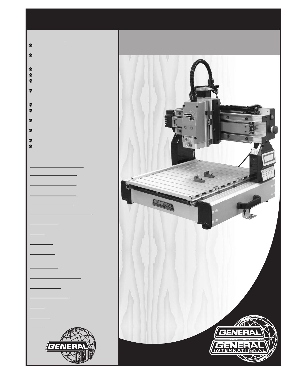
SETUP & OPERATION MANUAL
FEATURES
asy start-up procedure and unrivalled tech-
E
nical support.
arge user-friendly control panel with LCD dis-
L
lay, keypad and USB 2.0 port for easy file
p
transfers.
endant style hand-held operating contoller.
P
asy to learn i-Picture programming software.
E
Low backlash stepper motors for excellent
erformance and low maintenance.
p
Sliding table with rack and pinion transmis-
sion on "Y" axis and lead screw for "X" and "Z"
xis.
a
Positional accuracy up to 0.001 inches.
Variable cutting speeds up to 118 inches per
minute.
50 watt spindle included with automatic
1
spindle on/off control.
luminum table with integrated hold down
A
lamps.
c
Tool kit with starter cutting tools included.
Controller included, no external operating PC
required.
13" x 18" CNC CARVING MACHINE
SPECIFICATIONS
X AXIS CUTTING CAPACITY
13" (330 MM)
Y AXIS CUTTING CAPACITY
18" (457 MM)
Z AXIS CUTTING CAPACITY
3" (76 MM)
POSITIONAL ACCURACY
0.001”
OVERALL DIMENSIONS (W X L X H)
27 1/2” X 23 5/8”X 27 1/2” (699 X 540 X 699 MM)
SPINDLE SPEED
15 000 RPM
SPINDLE
150 WATT SPINDLE WITH BRUSHLESS MOTOR
MOTOR TYPE
LOW BACKLASH STEPPER MOTOR
BEARING TYPE
ALUMINUM BLOCK WITH REPLACEABLE NYLON
SLEEVES
TABLE SURFACE
ALUMINUM
PROGRAMMING SOFTWARE
i-Picture (included)
CUTTING SPEEDS
VARIABLE - UP TO 118 INCHES PER MINUTES
POWER REQUIREMENT
110 V, 2A
COLLETS
1/4” (6 MM)
WARRANTY
1 YEAR LIMITED
WEIGHT
62 LBS (18 KG)
MODEL
i-Carver
#40-913
REVISION 1 - NOVEMBER 19/2012
© Copyright General® International 11/2012
Page 2

GENERAL® INTERNATIONAL
8360 Champ-d’Eau, Montreal (Quebec) Canada H1P 1Y3
Telephone (514) 326-1161 • Fax (514) 326-5555 • www.general.ca
THANK YOU for choosing this General
®
International model i-Carver 40-913.This
13” x 18” CNC carving machine has been carefully tested and inspected before shipment and
if properly used and maintained, will provide you with years of reliable service. For your safety, as well as to ensure optimum performance and trouble-free operation, and to get the most
from your investment, please take the time to read this manual before assembling, installing
and operating the unit.
The manual’s purpose is to familiarize you with the safe operation, basic function, and features
of this CNC carving machine as well as the set-up, maintenance and identification of its parts
and components. This manual is not intended as a substitute for formal woodworking instruction, nor to offer the user instruction in the craft of woodworking. If you are not sure about the
safety of performing a certain operation or procedure, do not proceed until you can confirm,
from knowledgeable and qualified sources, that it is safe to do so.
Once you’ve read through these instructions, keep this manual handy for future reference.
Disclaimer: The information and specifications in this
manual pertain to the unit as it was supplied from the
factory at the time of printing. Because we are committed to making constant improvements, General
International reserves the right to make changes to
components, parts or features of this unit as deemed
necessary,without prior notice and without obligation to
install any such changes on previously delivered units.
Reasonable care is taken at the factory to ensure that
the specifications and information in this manual corresponds with that of the unit with which it was supplied.
However, special orders and “after factory” modifications may render some or all information in this manual
inapplicable to your machine. Further, as several gene-
®
rations of this model of CNC carving machine and several versions of this manual may be in circulation, if you
own an earlier or later version of this unit, this manual
may not depict your machine exactly. If you have any
doubts or questions contact your retailer or our support
line with the model and serial number of your unit for
clarification.
Page 3

GENERAL®& GENERAL®INTERNATIONAL WARRANTY
All component parts of General International, General CNC and Excalibur by General
International products are carefully inspected during all stages of production and each unit is
thoroughly inspected upon completion of assembly.
Standard 2-Year Limited Warranty
Because of our commitment to quality and customer satisfaction, General International
agrees to repair or replace any part or component which upon examination, proves to be
defective in either workmanship or material to the original purchaser for a period of 2 years
(24 months) from the date of purchase, subject to the “conditions and exceptions” as listed
below.
To file a Claim
To file a claim under our Standard 2-year Limited Warranty, all defective parts, components or
machinery must be returned freight or postage prepaid to General International or to a nearby
distributor, repair center or other location designated by General International. For further details
call our CNC technical support department at 1-877-340-8989 or submit a Technical Support
Ticket Request at http://generalcnc.ca/support_request.
Along with the return of the product being claimed for warranty, a copy of the original proof
of purchase and a “letter of claim” must be included (a warranty claim form can also be used
and can be obtained, upon request, from General International or an authorized distributor)
clearly stating the model and serial number of the unit (if applicable) and including an explanation of the complaint or presumed defect in material or workmanship.
CONDITIONS AND EXCEPTIONS:
This coverage is extended to the original purchaser only. Prior warranty registration is not
required but documented proof of purchase i.e. a copy of original sales invoice or receipt
showing the date and location of the purchase as well as the purchase price paid, must be
provided at the time of claim.
Warranty does not include failures, breakage or defects deemed after inspection by General®
International to have been directly or indirectly caused by or resulting from; improper use, or
lack of or improper maintenance, misuse or abuse, negligence, accidents, damage in handling or transport, or normal wear and tear of any generally considered consumable parts or
components.
Repairs made without the written consent of General® Internationallwill void all warranty.
Page 4

TABLE OF CONTENTS
Rules for safe operation . . . . . . . . . . . . . . .5
Electrical requirements . . . . . . . . . . . . . . .6
Grounding instructions . . . . . . . . . . . . . . . . . . . . . . .6
Circuit capacity . . . . . . . . . . . . . . . . . . . . . . . . . . . . .6
Extension cords . . . . . . . . . . . . . . . . . . . . . . . . . . . . .6
Identification of main parts
and components . . . . . . . . . . . . . . . . . . . .
Unpacking and preparation for set-up and
installation . . . . . . . . . . . . . . . . . . . . . . . .
Safety . . . . . . . . . . . . . . . . . . . . . . . . . . . . . . . . . . . . . .8
Unpacking . . . . . . . . . . . . . . . . . . . . . . . . . . . . . . . . .8
Placement within the shop /
Establishing a safety zone . . . . . . . . . . . . .
Installation and Assembly instructions . .10-11
Installation . . . . . . . . . . . . . . . . . . . . . . . . . . . . . . . .10
Optional stand . . . . . . . . . . . . . . . . . . . . . . . . . . . . .10
Adjusting the leveling feet . . . . . . . . . . . . . . . . . . .10
Mounting to a work surface . . . . . . . . . . . . . . . . . .10
Install the collet and collet nut . . . . . . . . . . . . . . .11
Cutting tool installation / removal . . . . . . . . . . . .11
Operating instructions . . . . . . . . . . . . . . .18
oint or origin . . . . . . . . . . . . . . . . . . . . . . . . . . . . . .18
P
Secure the workpiece . . . . . . . . . . . . . . . . . . . . . . .18
Load a GEE file for carving . . . . . . . . . . . . . . . . . . .18
Position the spindle over the point of origin . . . .20
Checking size of your image . . . . . . . . . . . . . . . . .21
Starting to carve . . . . . . . . . . . . . . . . . . . . . . . . . . .21
Speed selection . . . . . . . . . . . . . . . . . . . . . . . . . . . .21
Pause function . . . . . . . . . . . . . . . . . . . . . . . . . . . . .22
7
Concave carving on acrylic . . . . . . . . . . . . . . . . . .22
8
Advanced Operations . . . . . . . . . . . . . . . . . . . . . . . . .23
Using same point of origin as previous project .23
Manually adjusting jogging speed . . . . . . . . . . .23
Spindle manual positioning . . . . . . . . . . . . . . . . . .23
Turning spindle motor off/on . . . . . . . . . . . . . . . . .24
9
Changing unit setting from metric to imperial . .24
M3 Code . . . . . . . . . . . . . . . . . . . . . . . . . . . . . . . . . .24
Maintenance . . . . . . . . . . . . . . . . . . . .25-26
Periodic maintenance . . . . . . . . . . . . . . . . . . . . . .25
Lubrication . . . . . . . . . . . . . . . . . . . . . . . . . . . . . . . .25
Recommended optional accessories . . . . .26
i-Picture
i-Picture installation . . . . . . . . . . . . . . . . . . . . . . . . .12
Formatting your image files for i-Picture software .12
Converting a file to GEE code . . . . . . . . . . . . . . . .13
Settings . . . . . . . . . . . . . . . . . . . . . . . . . . . . . . . . . . .13
Preview . . . . . . . . . . . . . . . . . . . . . . . . . . . . . . . . . . .15
Convert . . . . . . . . . . . . . . . . . . . . . . . . . . . . . . . . . . .16
Exit software . . . . . . . . . . . . . . . . . . . . . . . . . . . . . . .16
Transfer GEE code file to usb flash drive . . . . . . . .16
software . . . . . . . . . . . . . . . . .12-16
Basic adjustments and controls . . . . . . . . . . .17
Connecting to a power source . . . . . . . . . . . . . . .17
On/Off power switch . . . . . . . . . . . . . . . . . . . . . . . .17
Indicator lights . . . . . . . . . . . . . . . . . . . . . . . . . . . . .17
Parts list & diagrams . . . . . . . . . . . . . .27-31
Contact information . . . . . . . . . . . . . . . . .32
Page 5

RULES FOR SAFE OPERATION
To help ensure safe operation, please take a moment to learn the machine’s applications and limitations, as well as potential hazards. General® International disclaims any real or implied warranty and holds itself harmless for any injury that
ay result from improper use of its equipment.
m
1. Be sure to read and understand owner’s manual
before operating.
2. Do not operate the i-Carver when tired, distracted,
r under the effects of drugs, alcohol or any med-
o
ication that impairs reflexes or alertness.
3. The working area should be well lit, clean and free
of debris.
4. Keep children and visitors at a safe distance when
the i-Carver is in operation; do not permit them to
operate the i-Carver.
5. Childproof and tamper proof your shop and all
machinery with locks, master electrical switches
and switch keys, to prevent unauthorized or unsupervised use.
6. Stay alert! Give your work your undivided atten-
tion. Even a momentary distraction can lead to serious injury.
7. Fine particulate dust is a carcinogen that can be
hazardous to health. Work in a well-ventilated area
and whenever possible use a dust collector and
wear eye, ear and respiratory protection devices.
8. Do not wear loose clothing, gloves, bracelets, neck-
laces or other jewelry while the i-Carver is in operation. Wear protective hair covering to contain long
hair and wear non-slip footwear.
9. Be sure that adjusting wrenches, tools, drinks and
other clutter are removed from the machine before
operating.
14. Always disconnect the tool from the power source
before servicing, changing accessories, performing any maintenance or cleaning, or if the
machine will be left unattended.
15. Make sure that switch is in
plugging in the power cord.
16. Make sure the tool is properly grounded. If equip-
ped with a 3-prong plug it should be used with a
three-pole receptacle. Never remove the third
prong.
17. Do not use this i-Carver for any purpose other than
its intended use. If used for other purposes,
AL INTERNATIONAL
warranty and holds itself harmless for any injury,
which may result from that use.
18. To reduce the risk of electric shock, do not operate
the machine with wet hands.
19. Be sure to read and understand every warning la-
bel before operating the machine. Make sure all
warning labels appear on the machine as indicated in section “Labels” on next page and that they
are fully legible. Immediately replace any illegible
or missing label before using the machine.
20. Respect the rated limits of this machine.
21. To ensure safety, all maintenance should be perfor-
med by a qualified technician.
22. To avoid electrical shock, do not touch the transfor-
mers, motors or control box when the power is on.
disclaims any real or implied
the “OFF”
position before
GENER-
10. Keep hands well away from the spindle, cutting
tools, and all moving parts. Use a brush, not hands,
to clear away chips and dust.
11. Before turning on the i-Carver, make sure the work-
piece is properly secured.
12. Use of parts and accessories NOT recommended
by
GENERAL INTERNATIONAL
ment malfunction or risk of injury.
13. Never stand on machinery. Serious injury could
result if the tool is tipped over.
may result in equip-
23. Make sure to always have full unimpeded access
to the emergency stop button at all times.
24. To ensure safety, do not tamper with the safety
cover, limit switch or any other accessories.
25. Be sure to keep a record before changing any set-
ting on the machine.
26. Place the unit on a sturdy surface, in a dry area.
27. Avoid exposing the machine to extremely high
temperatures.
28. Unplug the unit from the power source before
replacing fuses. Use only recommended fuses.
29. Be sure to turn off the machine when the power
source is unstable.
5
Page 6
ELECTRICAL REQUIREMENTS
BEFORE CONNECTING THE MACHINE TO THE POWER SOURCE, VERIFY THAT THE VOLTAGE OF YOUR POWER SUPPLY CORRE-
PONDS WITH THE VOLTAGE SPECIFIED ON THE MOTOR I.D. NAMEPLATE. A POWER SOURCE WITH GREATER VOLTAGE THAN
S
NEEDED CAN RESULT IN SERIOUS INJURY TO THE USER AS WELL AS DAMAGE TO THE MACHINE. IF IN DOUBT, CONTACT A QUAL-
FIED ELECTRICIAN BEFORE CONNECTING TO THE POWER SOURCE.
I
HIS TOOL IS FOR INDOOR USE ONLY. DO NOT EXPOSE TO RAIN OR USE IN WET OR DAMP LOCATIONS.
T
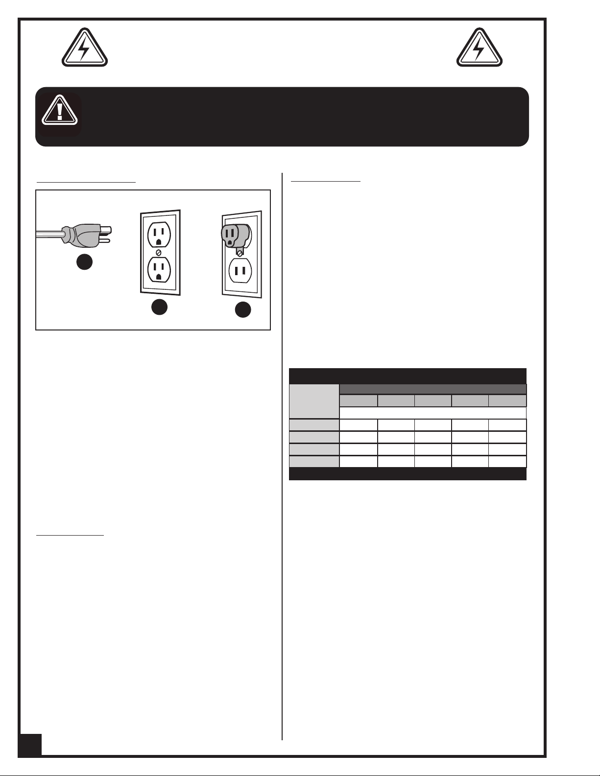
GROUNDING INSTRUCTIONS
A
B
In the event of an electrical malfunction or short circuit, grounding reduces the risk of electric shock. The
motor of this machine is wired for 110V single phase
operation and is equipped with a 3-conductor cord
and a 3-prong grounding plug A to fit a grounded
type receptacle B. Do not remove the 3rd prong
(grounding pin) to make it fit into an old 2-hole wall
socket or extension cord. If an adaptor plug is used C,
it must be attached to the metal screw of the receptacle.
Note: The use of an adaptor plug is illegal in some
areas. Check your local codes. If you have any doubts
or if the supplied plug does not correspond to your
electrical outlet, consult a qualified electrician before
proceeding.
C
EXTENSION CORDS
If you find it necessary to use an extension cord with your
machine, use only 3-wire extension cords that have 3prong grounding plug and a matching 3-pole receptacle that accepts the tool’s plug. Repair or replace a
damaged extension cord or plug immediately.
Make sure the cord rating is suitable for the amperage
listed on the motor I.D. plate. An undersized cord will
cause a drop in line voltage resulting in loss of power
and overheating. In some cases this may cause the
machine to stop its cutting operation and an error message will appear on your controller.
The accompanying chart shows the correct size extension cord to be used based on cord length and motor
I.D. plate amp rating. If in doubt, use the next heavier
gauge. The smaller the number, the heavier the gauge.
TABLE - MINIMUM GAUGE FOR CORD
AMPERE
RATING
< 5
6 TO 10
10 TO 12
12 TO 16
* NR = Not Recommended
110 VOLTS 50 FEET 100 FEET 200FEET 300 FEET
------->
------->
------->
------->
TOTAL LENGTH OF CORD IN FEET
AWG
18 16 16 14
18 16 14 12
16 16 14 12
14 12 * NR * NR
CIRCUIT CAPACITY
Make sure that the wires in your circuit are capable of
handling the amperage draw from your machine, as
well as any other machines that could be operating
on the same circuit. If you are unsure, consult a qualified electrician. If the circuit breaker trips or the fuse
blows regularly, your machine may be operating on a
circuit that is close to its amperage draw capacity.
However, if an unusual amperage draw does not exist
and a power failure still occurs, contact a qualified
technician or our service department.
6
Page 7
13” x 18” CNC CARVING MACHINE
MODEL i-Carver 40-913
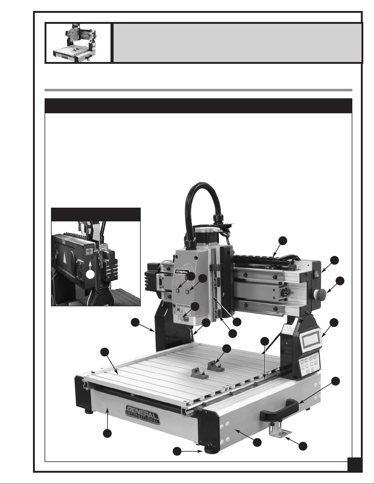
IDENTIFICATION OF MAIN PARTS AND COMPONENTS
MAIN ASSEMBLY - FRONT VIEW
A- FRAME
B- SIDE RAIL
C- WORK TABLE
D- GANTRY
E- Y AXIS SYSTEM
F- CABLE CHAIN
G- Z AXIS SYSTEM
H- SLIDE BLOCK
I- SPINDLE LOCKING BUTTON
J- CUTTING TOOL (BIT)
K- HAND-HELD PENDANT CONTROLLER
LEFT SIDE VIEW
N
L- WORKPIECE CLAMPS
M- STATUS LIGHT
N- USB PORT
O- SECURING BRACKETS
P- LEVELING FEET
Q- SYSTEM ERROR WARNING LIGHT
R- POWER ON/OFF SWITCH
S- STOP BUTTON
T- HANDLE
M
Q
F
R
S
I
D
C
A
P
J
G
H
E
L
B
O
K
T
7
Page 8
UNPACKING AND PREPARATION FOR SET-UP & INSTALLATION
SAFETY
THE MACHINE IS HEAVY (62 LBS - 28 KG). DO NOT OVEREXERT. ARRANGE TO HAVE HELP NEARBY AND READY FOR
UNPACKING AND SET UP.
THE SOUND LEVEL OF THIS MACHINE IS RATED AT APPROXIMATELY 85-95 DB DURING OPERATION. MAKE SURE THAT
ADEQUATE HEARING PROTECTION IS USED AND THAT THE OVERALL SOUND LEVEL WITHIN THE WORKING ENVIRONMENT IS TAKEN INTO CONSIDERATION.
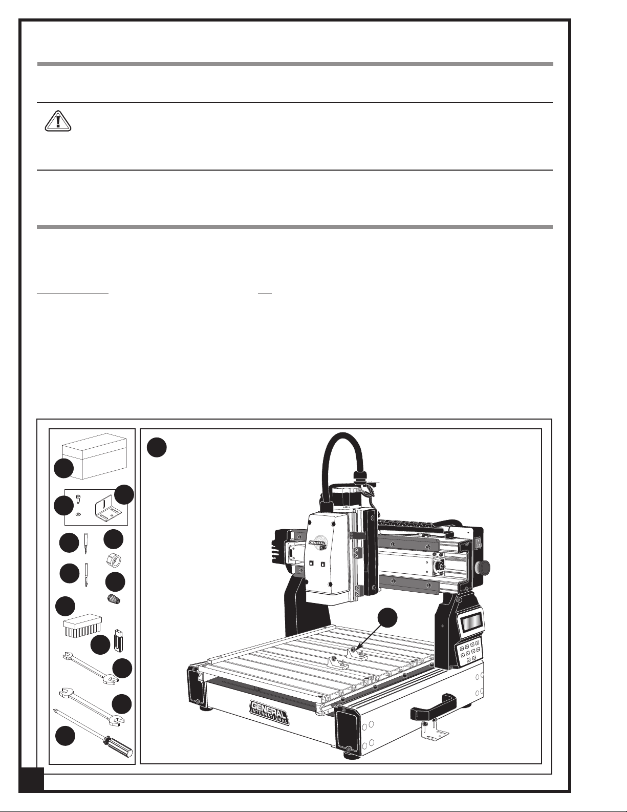
UNPACKING
Carefully unpack and remove the i-Carver and its components from the box and check for damaged or missing
items as per the list of contents below.
NOTE: Please report any damaged or missing items to your General International distributor immediately.
LIST OF CONTENTS QTY
A- TOOL BOX..............................................................................1
B- SOCKET SCREW W/WASHER .................................................2
C- SECURING BRACKETS............................................................2
D- 1/32" CONICAL/CARVING CUTTING TOOL........................1
E- 1/8" END MILL/MACHINING TOOL......................................1
F- ER11 COLLET NUT ..................................................................1
G- ER11 0.25" COLLET.................................................................1
H- BRUSH.....................................................................................1
M
A
C
B
D
F
E
G
H
I- USB FLASH DRIVE (including i-Picture software,
manual and 3D sample pictures) ................................1
J- 11-13 MM OPEN END WRENCH ...........................................1
K- 14-17 MM OPEN END WRENCH ...........................................1
L- PHILLIPS SCREWDRIVER.........................................................1
M- i-Carver .................................................................................1
N- WORKPIECE CLAMPS ............................................................2
N
I
J
K
L
8
Page 9
PLACEMENT WITHIN THE SHOP / ESTABLISHING A SAFETY ZONE
THIS i-Carver 40-913 IS HEAVY – 62 LBS (28 KG). DO NOT OVER-EXERT. THE HELP OF AN ASSISTANT WILL BE NEEDED
OR THE INSTALLATION.
F
ERIOUS PERSONAL INJURY COULD OCCUR IF YOU CONNECT THE MACHINE TO THE POWER SOURCE BEFORE YOU HAVE COM-
S
LETED THE INSTALLATION AND ASSEMBLY STEPS. DO NOT CONNECT THE MACHINE TO THE POWER SOURCE UNTIL INSTRUCTED
P
TO DO SO.
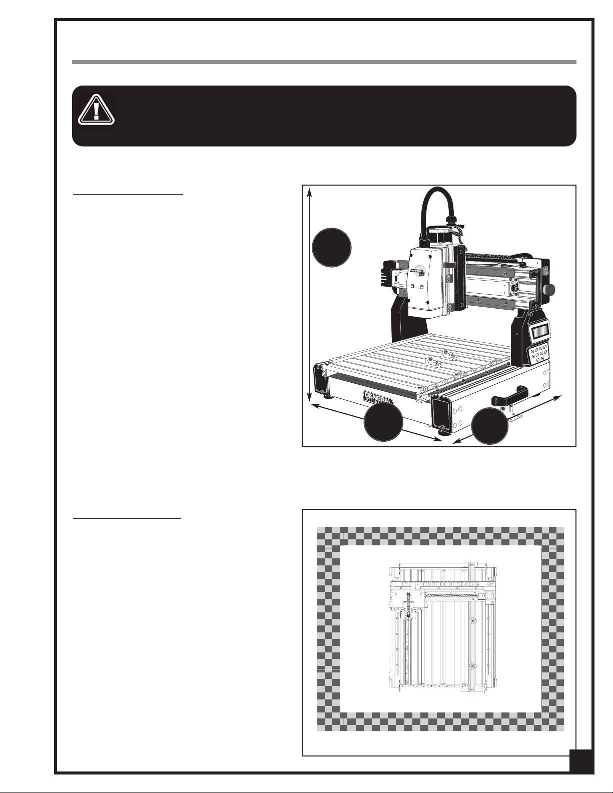
PLACEMENT WITHIN THE SHOP
This machine should be installed and operated
only on a solid, flat and stable work surface that is
able to support the weight of the i-Carver and the
workpiece.
Using the dimensions shown as a guideline, plan
for placement within your shop that will allow the
operator to work unencumbered and unobstructed by foot traffic (either passing shop visitors or
other shop workers) or other tools or machinery.
27
/2
1
”
ESTABLISHING A SAFETY ZONE
For shops with frequent visitors or multiple operators, it is advisable to establish a safety zone
around shop machinery. A clearly defined “nogo” zone on the floor around each machine can
help avoid accidents that could cause injury to
either the operator or the shop visitor.
It is advisable to take a few moments to either
paint (using non-slip paint) or using tape, define
on the floor the limits or perimeter of each
machines safety zone. Take steps to ensure that
all operators and shop visitors are aware that
these areas are off limits whenever a machine is
running for everyone but the individual operating the unit.
23
5/8
”
27
1/2
”
9
Page 10
INSTALLATION AND ASSEMBLY INSTRUCTIONS
For your convenience this i-Carver is shipped from the factory partially assembled and requires only minimal
assembly and set up before being put into service.
SERIOUS PERSONAL INJURY COULD OCCUR IF YOU CONNECT THE MACHINE TO THE POWER SOURCE BEFORE YOU HAVE COM-
LETED THE INSTALLATION AND ASSEMBLY STEPS. DO NOT CONNECT THE MACHINE TO THE POWER SOURCE UNTIL INSTRUCTED
P
TO DO SO.
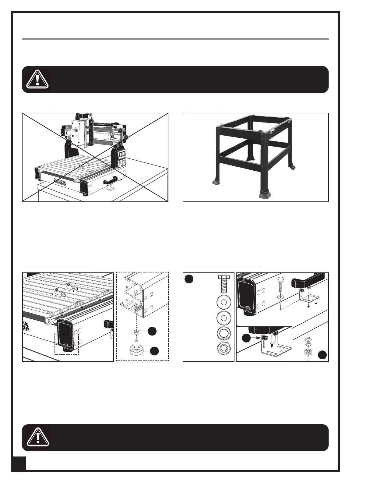
INSTALLATION
This machine should be installed and operated only
on a flat, sturdy and stable surface able to support the
weight of the machine (62 lbs - 28 kg) and the workpiece with ease.
Note: Never install the machine over the edge of a table
or workbench.
ADJUSTING THE LEVELING FEET
OPTIONAL STAND
If you prefer, an optional Heavy-duty open stand,
item #40-903, is available from your local General
International dealer.
MOUNTING TO A WORK SURFACE
C
HEX HEAD BOLT
After the i-Carver is placed in its final location, level the
feet by adjusting nut A up or down on the leveling feet
B as needed, then tightening down the nut.
FOR YOUR SAFETY IT IS ESSENTIAL THAT THE MACHINE DOES NOT ROCK OR TIP DURING OPERATION. MAKE SURE THAT THE
MACHINE IS FIRMLY SECURED TO THE WORK SURFACE, AND THAT THERE IS NO ROCKING, TIPPING OR CHATTERING.
10
FLAT WASHERS
A
B
LOCK WASHER
HEX NUT
E
D
If a permanent shop placement is practical, consider
drilling matching through holes in the mounting surface of your workbench or table to bolt the i-Carver in
place using hex bolts, flat washers, lock washers and
hex nuts
order shown in
Note: If needed, loosen the cap screws E and lower the
mounting brackets until they are flat against the table.
, C (fasteners not included), in the assembly
, D.
Page 11

INSTALL THE COLLET AND COLLET NUT
1. Fit the collet into the collet nut.
2. While pressing the spindle locking button to keep
the spindle from turning, insert the collet in the
spindle.
CUTTING TOOL INSTALLATION / REMOVAL
TO AVOID SERIOUS PERSONAL INJURY AND/OR DAMAGE TO THE SPINDLE, ALWAYS MAKE SURE THAT THE MACHINE HAS BEEN
TURNED OFF AND UNPLUGGED BEFORE INSTALLING/REMOVING A CUTTING TOOL.
KEEP HANDS WELL AWAY FROM THE SPINDLE, CUTTING TOOL, AND ALL MOVING PARTS AT ALL TIMES.
This model 40-913 i-Carver is supplied with two different cutting tools:
• # 40-917: 1/32" conical/carving cutting tool (for precision cutting and shapes).
• # 40-916: 1/8" end mill/machining cutting tool (for cleaning larger areas).
A
B C
Tighten
Loosen
To install a cutting tool (bit):
1. Insert the cutting tool in the collet, A.
2. While pressing the spindle locking button B to keep the spindle from turning, secure the cutting tool in the col-
let by tightening the collet nut counter clockwise with the supplied 17 mm open end wrench, C.
To remove a cutting tool (bit)
:
1. Lock the spindle in place by pressing the locking button while rotating the spindle until it locks in place, B.
2. While pressing on the spindle locking button, release the cutting tool (bit) by turning the collet nut clockwise with
the supplied 17 mm open end wrench.
11
Page 12

i-Picture
This i-Carver is supplied with i-Picture software. i-Picture converts images file to “GEE code”. GEE code is the programming language that your i-Carver will read and execute.
Note: i-Picture is compatible with Windows 98/me/2000/XP/Vista/7. It is not compatible with Mac OS X and Linux Operating Systems.
SOFTWARE
i-Picture
. Download i-Picture Software from the
1
2. Double-click on the installer icon to
INSTALLATION
supplied USB flash drive to your computer.
run the self-installing program.
FORMATTINGYOUR IMAGE FILES FOR
i-Picture is a converter software only. An image editing program such as Adobe Photoshop or MS Paint may be
required to convert your images to the required format type, color mode, and edit or modify an image, or to
create a new image.
i-Picture
SOFTWARE
Format type:
The format types accepted by i-Picture are : .gif, .png, .jpg, and .bmp. If needed, use an image editor to convert your image file to one of the formats listed above.
Color Mode:
i-Picture software is able to convert RGB images. However, when carving RGB image files, the result of your workpiece will not be clearly defined. The images have to be modified for grayscale* or black and white, using an
editing image software.
* Choose grayscale over black and white whenever possible to avoid large discrepancies between white and black
areas.
Images downloaded from the Internet:
Look for images that have higher resolution (300 x 300 dpi or higher) and significant contrast. Try to avoid
images that have too much fine detail.
Scanned Images:
- Scan your image in high resolution, in grayscale or black and white.
- Delete the background using an image editing software.
Photos from your Digital Camera:
- Adjust the light and avoid shadow while taking picture.
- Do not take a picture with your camera parallel to the object. A picture shows more dimensions with an
angle shot.
- Set your camera to the black and white mode to avoid the need for conversion in an image editing software
after.
12
Page 13

CONVERTING A FILE TO GEE CODE
1. Double-click on the i-Picture software
icon on your desktop to launch the
software.
2. From the File menu select:
Open Image File
To upload an image file:
(file formats: gif, png, bmp or jpg)
3. Select the file to carve, then click on
OPEN.
4. The selected image will appear in the
preview window.
SETTINGS
Scale Unit: [inch) or [mm]
Default scale unit is in inch. To change to
mm, click on the black arrow for a dropdown menu and select “mm”.
Note: “Size of Project (inch)” below will
change to “Size of Project (mm)” and the
values in the data fields below will change
accordingly.
Size of Project:
Determines the size of the carving on
your workpiece. The 3 boxes represent
the X/Y/Z axes (width/length/depth of
cut), respectively.
Note: Any change in the X and Y values (first
two boxes) will change the other proportionally. The Z axis (third box) is independent of
the other two and can be set to your choosing.
IMPORTANT! These dimensions represent
your image (machining area). The workpiece should be larger than these dimensions to avoid potential of machining outside the material and causing damage to
tooling, table and/or clamps!
13
Page 14
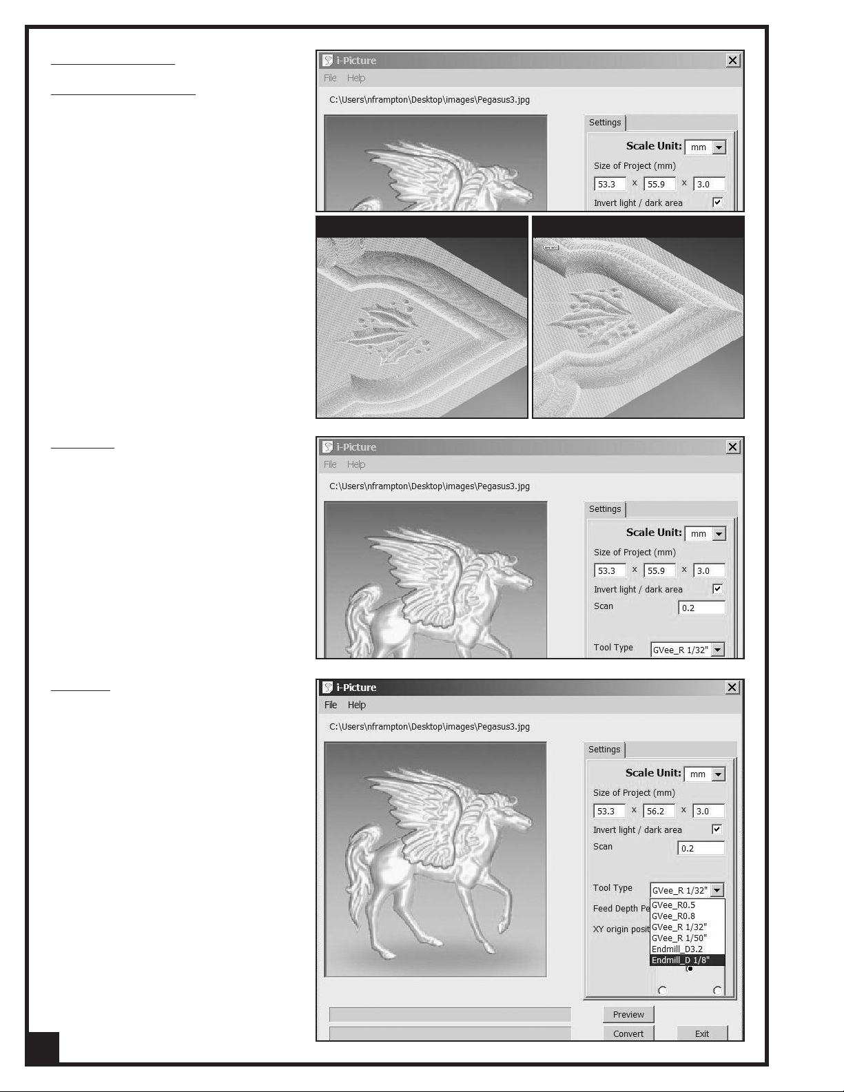
SETTINGS (CONTINUED)
Invert light/dark areas:
When a grayscale image is uploaded, i-
Picture defines the darker areas as the
deeper depth of cut, and the lighter areas
as the shallower depth of cut.
Check this box to invert the concave and
convex areas of the carving. (
ple on page 22.)
Scan step:
See exam-
BOX CHECKED
BOX UNCHECKED
Scan step is the distance that the Y axis
moves on every carving along the X axis.
The lower the number the Scan step, the
more detailed your image will be. Default
setting is 0.2 (mm) or 0.007874".
Tool Type:
Click on the black arrow for a drop-down
menu and select between the 6 tools listed:
• GVee_R 1/32":
supplied #40-917: 1/32" conical/ carv
ing cutting tool
• Endmill_D 1/8"
supplied #40-916 1/8" end mill
/machining cutting tool
if you are using the
if you are using the
14
Page 15

SETTINGS (CONTINUED)
Feed Depth Per Cycle:
epresents the depth of cut (Z axis) per
R
cycle.
The default setting is 27 mm.
For example: when Z is 10 mm and the
Feed Depth per Cycle is 24 mm, the cutter
will carve the workpiece in a single pass.
Conversely, when Z is 10 mm and the
Feed Depth per Cycle is 5 mm, the cutter
will carve the workpiece twice (2 passes)
in order to meet Z depth (per cycle = 5
mm; two cycles = 10mm).
XY Origin Position:
Select the XY Origin Position
Note that whatever you choose as the origin
position on the i-Carver must match the origin position you choose in i-Picture.
Center
Upper Left Corner
Upper Right Corner
Lower Left Corner
Lower Right Corner
PREVIEW
With all of the parameters set, click on the
PREVIEW button.
Note: The processing of the image preview
may take a few minutes, depending on its
complexity. Two dialog boxes will succesively pop up. Click OK to continue.
15
Page 16

PREVIEW (CONTINUED)
Workpiece Preview window pops up
showing the final image preview in 3D.
Note: Use the red line across this window to
change the view at will.
If the image preview doesn’t conform to
what you expected, close the preview
window and modify the settings as needed.
CONVERT
1. If the image preview conforms to what
was expected, close the preview window, then, from the i-Picture window,
click on the CONVERT button.
2. A new “save as file” window will open.
Type the name of the file in the “file
name” field. The .
automatically be added to the end of
the file name.
Note: The conversion of the image into GEE
code may take a few minutes, depending on
it’s complexity. A dialog box will pop up.
Click OK to continue.
GEE extension will
EXIT SOFTWARE
1. Click on the EXIT button to exit
i-Picture software.
or, from File menu select EXIT.
TRANSFER GEE CODE FILE TO USB FLASH DRIVE
1. Save your GEE code file on the sup-
plied USB flash drive.
16
Page 17

BASIC ADJUSTMENTS & CONTROLS
CONNECTING TO A POWER SOURCE
TO REDUCE THE RISK OF SHOCK OR FIRE DO NOT OPERATE THE UNIT WITH A DAMAGED POWER CORD OR
PLUG. REPLACE DAMAGED CORD OR PLUG IMMEDIATELY.
TO AVOID UNEXPECTED OR UNINTENTIONAL START-UP, MAKE SURE THAT BOTH OF THE POWER SWITCHES ARE
IN THE OFF POSITION BEFORE CONNECTING TO A POWER SOURCE.
Once the assembly steps have been
completed and the unit is safely secured
to a work surface, uncoil the power cord
and plug the power cord into an appropriate outlet.
Refer back to the section entitled “Electrical Requirements” and make sure all
requirements and grounding instructions
are followed.
When carving operations have been
completed unplug the i-Carver from the
power source.
SWITCH OFF
SWITCH OFF
ON/OFF POWER SWITCH
To START the carver: Push switch A UP to power the iCarver ON. The “power on” indicator light B will illuminate.
To STOP the carver
Then, push switch A DOWN to power OFF the i-Carver.
Note: Once the RED “STOP” button has been pressed, the
machine can only be started by turning clockwise to
release the button.
: Press on the RED “STOP” BUTTON, C.
INDICATORLIGHTS
• Green light D is ON: Indicates that electrical current is
flowing into the machine.
• Green light
is running.
• Red light
and an error message is displayed on the LCD screen
on the control panel.)
D is FLASHING: Indicates that the program
E is ON: System error (green light E turns OFF
B
A
C
D
E
17
Page 18

OPERATING INSTRUCTIONS
POINT OF ORIGIN
POINT OF ORIGIN: CENTERPOINT OF ORIGIN : LEFT CORNER
You can choose to place the point of origin of the carving, either on one corner or on the center of your workpiece. The same origin position you chose in iPicture should be duplicated here
Note: If you choose the center of the board as the point of origin, trace an “X” on the center point of the board with a
pencil as shown above on right.
SECURE THE WORKPIECE
.
B
A
C
1. Place your board on the i-Carver table, flush
against the left position plate as shown in A.
2. Loosen the Phillips head screws B on both work
piece clamps C, then move the two clamps
againts the board.
LOAD A GEE FILE FOR CARVING
D
E
3. Re-tighten the screws to lock clamps in position as
shown in D.
4. Tighten the locking screw E on both clamps
against the board to secure it in place.
A
1. Insert the USB flash drive into the USB port A, locat-
ed on the left side of the i-Carver.
18
2. Turn the power switch on.
Page 19

X+Y+Z
+
Up
X-Y-Z
-
Enter Back
Down
X+Y+Z
+
Up
X-Y-Z
-
Enter Back
Down
X+Y+Z
+
Up
X-Y-Z
-
Enter Back
Down
X+Y+Z
+
Up
X-Y-Z
-
Enter Back
Down
Upon turning the power switch on, the spindle automatically returns to the Home position (top left).
X+Y+Z
+
Up
X-Y-Z
-
Enter Back
Down
X+Y+Z
+
Up
X-Y-Z
-
Enter Back
Down
3. A welcome message is displayed on the LCD
screen on the control panel.
Press on the [ENTER] key on the control panel.
5. The three reminder messages above will be dis-
played on the LCD screen. Press on the [ENTER] key
to skip and continue on each message.
4. Once the spindle has returned to home position,
the message above is displayed on the LCD screen.
Press on the [ENTER] key on the control panel.
6. The main menu will appear.
7. Using the [UP] or [DOWN] key, move the cursor to
SELECT FILE, then press on [ENTER].
The system will search for
drive, then all the
GEE
GEE
files on the USB flash
files found on the USB flash
drive will be displayed on the LCD screen.
8. Use the [UP] or [DOWN] key to select the
GEE
file to
carve.
GEE
9. With the cursor next to the
file to carve, press
on [ENTER].
Note: the LCD screen can display a maximum of 48 files.
19
Page 20

X+Y+Z
+
Up
X-Y-Z
-
Enter Back
Down
POSITION THE SPINDLE OVER THE POINT OF ORIGIN
X+Y+Z
+
Up
X-Y-Z
-
Enter Back
Down
X+Y+Z
+
Up
X-Y-Z
-
Enter Back
Down
X+Y+Z
+
Up
X-Y-Z
-
Enter Back
Down
X+Y+Z
+
Up
X-Y-Z
-
Enter Back
Down
X+Y+Z
+
Up
X-Y-Z
-
Enter Back
Down
1. Press on the [BACK] key to go back to the main
menu.
2. Using the [UP] or [DOWN] key select POSITION, then
press on [ENTER].
4. Use the [X+], [X-], [Y+] or [Y-] keys on the control
panel to move the spindle over the point of origin.
3. Using the [UP] or [DOWN] key, select MANUAL JOG
MODE, then press on [ENTER].
Note: It is important to slightly penetrate the cutter
into the board so your intended carving will cover
your board in case your
board is not perfectly flat.
5. Use the [Z+] or [Z-] key to lower the spindle until the
cutting tool (bit) slightly pierces into the board.
6. Move cursor to ENTER TO SET ORG then press
[ENTER] to confirm spindle positionning.
7. Once the point of origin has been set, the confir-
mation message above is displayed.
20
Press [ENTER] to continue.
8. X,Y and Z values are now all back to 0.0.
Press on the [BACK] key to continue. The screen will
display the carving dimension settings.
Page 21

CHECKING SIZE OF YOUR IMAGE
X+Y+Z
+
Up
X-Y-Z
-
Enter Back
Down
X+Y+Z
+
Up
X-Y-Z
-
Enter Back
Down
X+Y+Z
+
Up
X-Y-Z
-
Enter Back
Down
X+Y+Z
+
Up
X-Y-Z
-
Enter Back
Down
To inspect your work to ensure correct size:
1. Move the cursor to BORDER, then press on [ENTER].
Note: During the border inspection the tool should move
only where there is material below it. If the tool begins to
move outside the material hit the Emergency Stop button
immediately to avoid hitting a clamp. Review your image
area and configuration of X and Y axis to determine
where the error lies.
STARTING TO CARVE
Important! Do not cut the project until the border
inspection is successful! (see previous step)
To start carving your artwork:
1. Select PROCESS, then press on [ENTER].
2. The message above will appear, then on comple-
tion of border inspection, the previous menu will
be displayed.
Note: Refer to the section below for helpful hints on
speed selection.
2. Select the carving speed (LOW, NORMAL or HIGH)
then press on [ENTER]. The i-Carver will start carving your artwork.
SPEED SELECTION
Selecting the appropriate feed rate is dependant on a variety of factors: type and density of the material to be
machined, depth of cut per pass, type of bit or cutting tool being used, required finish quality, as well as the
amount of fine detail in the image being machined. There are no hard and fast rules. Be patient: practice and
experience will be your best teacher.
There are however some general guidelines to consider and the following information will help you in selecting
the correct feed rate:
Low Speed - For projects where material density is extremely high. This setting is not commonly used.
Normal Speed - Best speed for raster based programs created from iPicture when using dense woods, or
where machining depths exceed 1/4" per pass
High Speed - For raster based programs in less dense woods with machining depths of 1/4" or less per pass.
For further assistance with issues regarding feed rate selection, consult the trouble shooting guide available on
the General CNC website at www.generalcnc.ca
21
Page 22

PAUSE FUNCTION
X+Y+Z
+
Up
X-Y-Z
-
Enter Back
Down
PUSH
POUSSER
When the i-Carver is carving your artwork, the percentage (%) of work in progress is displayed on the LCD
screen, A.
The pause function, B, allows the operator to pause to:
•
Clear dust from the workpiece
•
Examine the work performed to that point
•
Change the bit
nd then resume the program when needed.
a
B
A
1. Press [ENTER] to pause the program.
2. After the cleaning/examination/tool change is done
and you are ready to continue, press on [ENTER] once
to resume carving.
When the pause function is activated:
•
The program stops running
•
The main spindle raises
•
The spindle stops
CONCAVE CARVING ON ACRYLIC
For carving on material other than wood such as ACRYLIC, the instructions are the same as for NORMAL CONVEX CARVING ON WOOD (page 13 to 22), except for the steps below:
Formattingyourimagefilein an image editingsoftware (p.12):
1. Open your image in an editing program such as
Adobe Photoshop or MS Paint and flip the image
as shown above.
Setting your image file parameters in
i-Picture
(p.13):
2. In i-Picture settings, check box invert light/dark
areas to invert the concave and convex areas of
the carving.
Preparing and securing your workpiece (p.18):
1. Put at least four strips of double sided tape on the
back of you acrylic board A.
Note: The number of strips you should be using depends on
the size of your workpiece. In this exemple, the workpiece size
is A3 (297 x 420 mm - 11.69” x 16.54”).
A
2. Prepare a wood board, larger than your acrylic
board and planed on both sides.
3. Remove the protective strip from the tape and adhere the acrylic board to the wood board.
B
Positioning the spindle over the point of origin (p.20)
4. When positioning the spindle over the chosen point of origin, it is important to slightly penetrate the cutter into
22
the acrylic
board B so your intended carving will cover your board in case your board is not perfectly flat.
Page 23

X+Y+Z
+
Up
X-Y-Z
-
Enter Back
Down
X+Y+Z
+
Up
X-Y-Z
-
Enter Back
Down
ADVANCED OPERATIONS
X+Y+Z
+
Up
X+Y+Z
+
Up
X-Y-Z
-
Enter Back
Down
X+Y+Z
+
Up
X-Y-Z
-
Enter Back
Down
X+Y+Z
+
Up
X-Y-Z
-
Enter Back
Down
USING SAME POINT OF ORIGIN AS PREVIOUS PROJECT
Once a point of origin have been set once, a new
option appears in POSITION menu, allowing you to
use the same point of origin as the previous project
nstead of having to position the spindle over the
i
point of origin again.
1. Upon completion of the first carving, move the
cursor to SELECT FILE, then press on [ENTER].
2. Load the next project to carve.
MANUALLYADJUSTING JOGGING SPEED
Jogging speed can be set to 60 rpm (2) or 240 rpm
(4).The default setting is 60 rpm ( 2).To set the jogging
speed to 240 rpm (4):
1. In POSITION menu, select MANUAL JOG MODE
then press on [ENTER].
2. Select X then press on [ENTER]. The cursor will turn
into a flashing block for adjustment status.
3. Press on [UP] key to change X value to 4.
3. In POSITION menu, select OLD ORIGIN then press
on [ENTER].
4. Press on [BACK] key to exit adjustment status.
The flashing block will turn back into an arrow.
5. Repeat steps 2 to 4 for the Y and Z axes.
SPINDLE MANUAL POSITIONING
The spindle can be positioned by dialing the coordinates of the X, Y and Z axes.
1. In POSITION menu, move the cursor to COORDI-
NATE MODE, then press [ENTER].
2. Select X then press [ENTER].The cursor will turn into
a flashing block for adjustment status.
3. Using the [UP] or [DOWN] key, set the X value.
4. Press on [BACK] key to exit adjustment status. The
flashing block will turn back into an arrow.
5. Once the X, Y and Z coordinates has been set to
the required value, select MOVE AND SET ORG,
then press on [ENTER].
23
Page 24

When using MANUAL JOG MODE, the user can turn
X+Y+Z
+
Up
X-Y-Z
-
Enter Back
Down
X+Y+Z
+
Up
X+Y+Z
+
Up
X-Y-Z
-
Down
X+Y+Z
+
Up
X-Y-Z
-
Enter Back
Down
X+Y+Z
+
Up
X-Y-Z
-
Enter Back
Down
the spindle motor OFF to avoid any accidental contact with the spindle turning at high speed, which
could cause serious personal injuries and/or dam-
ge to the spindle.
a
KEEP HANDS WELL AWAY FROM THE
SPINDLE, CUTTING TOOLS, AND ALL
MOVING PARTS.
1. In MAIN menu, select POSITION then press [ENTER].
2. Select SPINDLE MOTOR OFF then press [ENTER]. The
cursor will turn into a flashing block for adjustment
status.
3. Using the [UP] or [DOWN] key, set the spindle motor
ON or OFF
CHANGING UNIT SETTING FROM METRIC TO IMPERIALTURNING SPINDLE MOTOR OFF/ON
The default scale unit setting is in metric (mm). To
change to imperial (inches):
1. In MAIN menu, select CONFIGURATION then press
[ENTER].
2. Select UNIT : MM then press [ENTER]. The cursor
will turn into a flashing block for adjustment
status.
4. Press on [BACK] key to exit adjustment status. The
flashing block will turn back into an arrow.
M3 CODE
With standard NC code, opening/closing the M3 code
allows you to turn the spindle on/off.
The spindle will not rotate. It will execute the program
on the X, Y and Z axis but without engraving.
To turn the spindle OFF
1. In MAIN menu, select CONFIGURATION then press
[ENTER].
2. Select M3 CODE : OPEN then press [ENTER]. The
cursor will turn into a flashing block for adjustment
status.
24
3. Press [DOWN] key to change to IN.
4. Press [BACK] key to exit adjustment status.
5. Press [BACK] key again to go back to MAIN
menu.The coordinates are now displayed in
INCHES.
This setting will remain after turning the carver off. To
revert back to metric (mm) go back to CONFIGURATION menu and select UNIT : MM
Page 25

X+Y+Z
+
Up
X-Y-Z
-
Enter Back
Down
o turn the spindle ON
T
. Press [DOWN] key to change to M3 CODE : CLOSE.
1
2. Press [BACK] key to exit adjustment status.
3. Press [BACK] key again to go back to MAIN menu.
MAINTENANCE
MAKE SURE THE MACHINE HAS BEEN TURNED OFF AND UNPLUGGED FROM THE POWER SOURCE
BEFORE PERFORMING ANY MAINTENANCE.
PERIODIC MAINTENANCE
• Inspect/test the ON/OFF switch before each use. Do not operate the i-Carver with a damaged switch; replace
a damaged switch immediately.
• Keep the machine clean and free of saw dust, woodchips, pitch or glue. Vacuum or brush off any loose debris
and wipe down the machine and table occasionally with a damp rag.
• Periodically inspect the power cord and plug for damage. To minimize the risk of electric shock or fire, never
operate the i-Carver with a damaged power cord or plug. Replace a damaged power cord or plug at the first
visible signs of damage.
• Regularly inspect carved workpieces for signs of cutting tool damage or wear and replace damaged or worn
cutting tools immediately.
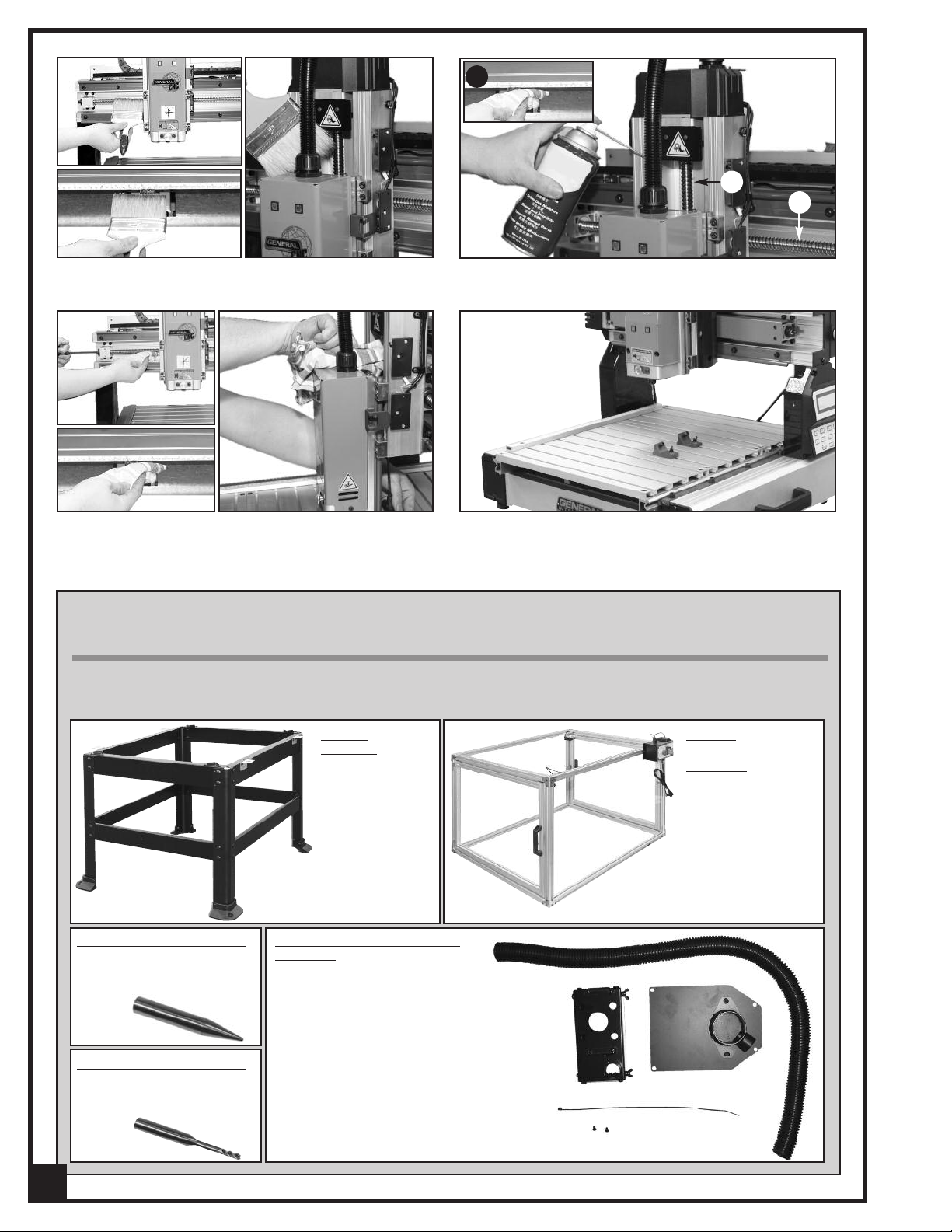
LUBRICATION
To prevent dirt or dust build-up, cleaning and lubrication of the 3 lead screws is recommended after every 60 hours of
operation.
1. Disconnect the machine from the power source.
A
2. Using a 4 mm Allen wrench, rotate the X axis lead
screw A to move the spindle more or less to the middle of the machine.
C
3. For the X Axis
B
B
: Remove the 4 Philips head screws B
on the guard and remove the guard.
D
4. Pull the table backward, C, to expose the rack and
gear.
5. For the Z Axis
: Expose the lead screw by loosening
cap screw D with a 4 mm Allen wrench to move the
spindle downward.
25
Page 26
C
A
B
6. Using a long soft bristled brush clean the wood
chips and dust from the 3 lead screws
.
8. While applying oil, turn each lead screw and use a
7. Oil the 3 lead screws, A, B and C, using SAE 20 or
lower machine oil.
9. Re-install the guard and the table.
clean dry cloth to wipe off any excess oil.
RECOMMENDED OPTIONAL ACCESSORIES
Here are some of the optional accessories available from your local General International dealer. For more
information about our products, please visit our website at www.general.ca
Conical cutter # 40-917
conical/carving tool
1/32"
for precision cutting and
shape.
End mill cutter # 40-916
end mill/machining
1/8"
tool for cleaning larger
areas.
26
STAND
#40-912
For model 40-913
only.
DUST COLLECTION OUTLET
# 40-928
Contains:
- Dust collection skirt
- Flexible hose
- Fust chute with plate
- Tie wrap
SAFETY
ENCLOSURE
# 40-918
Ideal for educational
users. Impact resistant Lexan™. Safety
inter-lock door (autoshut-off).
For model 40-913
only
Page 27

3
11
21
22
23
19
24
25
16
26
27
181917
.1
7
.2
20
15
16
40
7
A
C
A
B
B
29
31
32
30
34
36
37
36
39
40
41
14
48
49
8
43
8
51
50
45
46
16
47
52
10
32
31
30
29
34
35
36
37
36
39
38
10
89
141
83
90
10
83
141
.2
86
.3
53
16
54
82
16
46
55
16
59
58
57
56
16
66
12.2
80
79
71
76
75
70
71
2
40
7
13
69
33
10
44
60
67
64
72
4
5
8
14
9
10
38
10
9
*
68
1
57
61
12.1.1
12.1.2
62
63
64
65.1
66
66
62
81
73
74
78
77
*
141
65
87
88
135
.3
.2
.1
9
10
123
40
41
40
10
97
11
142
137
136
6
89
10
132
*
138
42
42
1
DIAGRAM-1
27
Page 28

.3
.4
.1
.2
D
D
1
1
107
108
108
107
8
118
55
112
122
90
10
122
111
8
116
117
8
115
115
112
16
116
117
8
8
119
120
121
114
113
16
111
14
84
85
105
29
30
104
102
103
98
99
10
94
94
95
10
8
8
96
C
16
71
10
100
101
8
85
109
8
85
109
106
110
110
.5
.3
.4
.1
.2
.5
93
92
28
91
*
129
128
127
126
125
124
X 2
16
DIAGRAM - 2
28
Page 29

PARTS LIST — i-Carver 40-913
REF # PART. N0. DESCRIPTION SPECIFICATIONS QTY
1 40913-01 BUTTON HEAD SCREW M6 x 1.0P x 16/6.1 x 12.3/6.3 x 13 x 1.0t 26
2 40913-02 ALUMINUM RAIL (ZL) 6061 1
3 40913-03 ALUMINUM RAIL (ZR) 6061 1
4 40913-04 SLIDE BLOCK (Z) 6463 1
5 40913-05 SLIDE PLATE 6463 1
6 40913-06 HANGING HOOK 1
7 40913-07 SLIDE BLOCK COMPLETE WJ200UM-01-10 8
7.1 40913-7-1 NYLON SLEEVE 8
7.2 40913-7-2 SLIDE BLOCK 8
8 40913-08 CAP SCREW M6 x 1.0P x 10 48
9 40913-09 SPROCKET WASHER 4.3 x 8.5(BW-4) 7
10 40913-10 BUTTON HEAD SCREW M4 x 0.7P x 8 31
11 40913-11 CAP SCREW M5 x 0.8P x 10 5
12 40913-12 MAIN SPINDLE MOTOR COMPLETE 1
12 40913-12-1 MAIN MOTOR & DRIVER BOARD ASS'Y 15000rpm 150W/110V/60Hz 1
12.1.1 40913-12-1-1 MAIN MOTOR 1
12.1.2 40913-12-1-2 SPINDLE DRIVER BOARD (110V) 1
12.2 40913-12-2 POWER SUPPLY NES-150(110V) 1
13 40913-13 COLLET 1
14 40913-14 CAP SCREW M6 x 1.0P x 16 10
15 40913-15 TOUCH PLATE (Z) 1
16 40913-16 BUTTON HEAD SCREW M5 x 0.8P x 10 26
17 40913-17 BALL BEARING 6002-2NKE 1
18 40913-18 SPINDLE BOTTOM COVER SPHC 1
19 40913-19 BUTTON HEAD SCREW M5 x 0.8P x 8 6
20 40913-20 SPECIAL NUT S45C 1
21 40913-21 SPINDLE BOTTOM COVER 6463 1
22 40913-22 SPRING SUP6 1
23 40913-23 STEEL PLATE SPHC 1
24 40913-24 LOCKING PIN S45C 1
25 40913-25 SPINDLE FRONT COVER 1
26 40913-26 LED LAMP (G) 1
27 40913-27 LED LAMP (R) 1
29 40913-29 CAP SCREW M4 x 0.7P x 12 12
30 40913-30 STEP MOTOR 3
31 40913-31 STEP MOTOR SEAT (X) 6463 2
32 40913-32 CAP SCREW M6 x 1.0P x 20 4
33 40913-33 STEEL PLATE SPHC 1
34 40913-34 COUPLING Ø8 x Ø10 x L31 2
35 40913-35 LEAD SCREW COMPLETE FOR X AXIS 1
36 40913-36 THRUST BEARING 51201(Nachi) 4
37 40913-37 SUPPORT BLOCK 6463 2
38 40913-38 CAP SCREW M6 x 1.0P x 12 8
39 40913-39 SPECIAL NUT MR12 x 1.0P 2
40 40913-40 CAP SCREW M5 x 0.8P x 20 24
41 40913-41 LOCK WASHER 5.1 x 9.3 8
42 40913-42 FLAT WASHER 5.2 x 10 x 1t 8
43 40913-43 SPINDLE SADDLE 6463 1
44 40913-44 STEPPER MOTOR COVER (Z) 1
45 40913-45 SELF TAPPING SCREW M3 x 1.06P x 15 4
46 40913-46 LIMIT SWITCH 4
47 40913-47 LIMIT SWITCH COVER 1
48 40913-48 PLASTIC CORRUGATED TUBING 1
49 40913-49 CABLE GLAND BRACKET SPHC 1
50 40913-50 SLIDING BLOCK (X) 6463 1
51 40913-51 TOUCH PLATE (X) SPCC 1
29
Page 30

PARTS LIST — i-Carver 40-913
EF. # PART N0. DESCRIPTION SPECIFICATION QTY
R
52 40913-52 COVER FOR LEAD SCREW SPHC 1
53 40913-53 RAIL FOR X AXIS 6061 2
54 40913-54 STEPPER MOTOR COVER (X) 1
55 40913-55 BUTTON HEAD SCREW M3 x 0.5P x 15 8
56 40913-56 CROSS BEAM 6463 1
57 40913-57 COUNTERSUNK SCREW M4 x 0.7P x 10 4
58 40913-58 CABLE CHAIN L-513mm (19-links) 1
59 40913-59 CABLE CHAIN SEAT SPHC 1
60 40913-60 CORD PROTECTOR AMB-3 x 65mm 1
61 40913-61 COLD PLATE 6463 1
62 40913-62 HEX BOLT M3 x 0.5P-10L 8
63 40913-63 COLD PLATE 1
64 40913-64 BUTTON HEAD SCREW M3 x 0.5P x 10 8
65 40913-65 CONTROLLER COMPLETE 13" 1
65.1 40913-65-1 CONTROL BOARD 13" 1
65.2 40913-65-2 KEYPAD CIRCUIT BOARD 1
65.3 40913-65-3 LCD SCREEN WH2004A 1
66 40913-66 BUTTON HEAD SCREW M3 x 0.5P x 6 10
67 40913-67 COLD PLATE 1
68 40913-68 CAP SCREW M4 x 0.7P x 8 2
69 40913-69 LEAD SCREW COMPLETE FOR Z AXIS PITCH 5_ 1
70 40913-70 ELECTRIC BOX COVER 1
71 40913-71 BUTTON HEAD SCREW M5 x 0.8P x 8 12
72 40913-72 FAN DC 24V 2.04W 1
73 40913-73 FAN COVER ABS 1
74 40913-74 SELF TAPPING SCREW M4 x 1.59P x 25 4
75 40913-75 LOOP WIRE CONCENTRATOR 2
76 40913-76 SELF TAPPING SCREW M5 x 1.59P x 8L 4
77 40913-77 POWER CORD 1
78 40913-78 CABLE GLANDS MGB16-10B 1
79 40913-79 POWER SWITCH 1
80 40913-80 EMERGENCY STOP (ALE16) 1
81 40913-81 POWER INDICATOR LAMP DC 24V-LED-_10 1
82 40913-82 SIDE COVER 1
83 40913-83 VERTICAL POST 2
84 40913-84 SPRING WASHER 6.1 x 12.3 4
85 40913-85 FLAT WASHER 6.3 x 13 x 1t 6
86 40913-86 SELF TAPPING SCREW M3 x 1.06P x 6 4
87 40913-87 SELF TAPPING SCREW M2 x 0.63P x 6L 4
88 40913-88 KEYPAD UPPER COVER COMPLETE 1
88.1 40913-88-1 KEYPAD UPPER COVER 1
88.2 40913-88-2 TRANSPARENT STICKER 1
88.3 40913-88-3 KEYPAD STICKER 1
89 40913-89 VERTICAL POST COVER 2
90 40913-90 WIRE CLAMP ACC-3-B 2
91 40913-91 CAP SCREW M6 x 1.0P x 8 3
92 40913-92 ALUMINUM STICK 6463 1
93 40913-93 SQUARE NUT M6 x 1.0P 3
94 40913-94 ALUMINUM TUBE (T) 6463 2
95 40913-95 TOUCH PLATE (Y) SPCC 2
96 40913-96 ALUMINUM TABLE 6463 3
97 40913-97 WIRE CLAMP ACC-1.5-B 1
98 40913-98 RACK 6061 3
99 40913-99 FLAT WASHER 4.3 x 14 x 1.8t 2
100 40913-100 WIRE CLAMP ACC-2-B 1
101 40913-101 BUTTON HEAD SCREW M4 x 0.7P x 12 6
30
Page 31

PARTS LIST — i-Carver 40-913
REF.# PART N0. DESCRIPTION SPECIFICATION QTY
102 40913-102 CLAMP 2
102.1 40913-102-1 CLAMP BODY 1
102.2 40913-102-2 SQUARE NUT SPHC 1
102.3 40913-102-3 PHILLIPS HEAD SCREW M5 x 0.8P x 18 1
102.4 40913-102-4 LOCK WASHER 5.1 x 9.3 1
102.5 40913-102-5 PHILLIPS HEAD SCREW M6 x 1.0P x 16 1
103 40913-103 GEAR 1
104 40913-104 SET SCREW M4 x 0.7P x 8 2
105 40913-105 STEPPER MOTOR SEAT (Y) 6463 1
106 40913-106 SHIELD 1
107 40913-107 CAP SCREW M8 x 1.25P x 25 4
108 40913-108 HANDLE 2
109 40913-109 FIXED PLATE 2
110 40913-110 PLUG HP-13G 16
111 40913-111 TUBE COVER 2
112 40913-112 TUBE COVER 2
113 40913-113 ALUMINUM TUBE (BL) 6463 1
114 40913-114 ALUMINUM TUBE (BR) 6463 1
115 40913-115 RAIL FOR Y AXIS 6061 2
116 40913-116 HEX. NUT 4
117 40913-117 FOOT PAD S20C+NBR 4
118 40913-118 LIMIT SWITCH 2
119 40913-119 ALUMINUM TUBE (F) 6463 1
120 40913-120 ALUMINUM TUBE (M) 6463 1
121 40913-121 ALUMINUM TUBE (B) 6463 1
122 40913-122 SNAP BUSHING NB-1925 2
123 40913-123 CHASSIS TIE ALT-150M-B 1
124 40913-124 TOOL KIT 1
125 40913-125 BRUSH 125 x 54 x 40 1
126 40913-126 11/13 MM COMBINATION WRENCH 11 x 13 1
127 40913-127 14/17 MM COMBINATION WRENCH 14 x 17 1
128 40913-128 SCREWDRIVER #1 x 75 1
129 40913-129 TOOL BOX 175(L) x 110(W) x 95(H) 1
132 40913-132 USB FLASH DRIVE 1
135 40913-135 SELF TAPPING SCREW M4 x 1.59P x 12L _ 4
136 40913-136 KEYPAD BOTTOM COVER 1
137 40913-137 KEYPAD HANGING RECEPTACLE 1
138 40913-138 CHASSIS TIE BT-1 x 80mm 1
141 40913-141 CAP SCREW WITH WASHER M6 x 1.0P x 16/6.1 x 12.3 8
142 40913-142 SELF TAPPING SCREW M4 x 1.59P x 8L _ 2
Notes
31
Page 32

MODEL i-Carver 40-913
835, Cherrier Street, Drummondville (Quebec) Canada J2B 5A8
Tel.: (514) 326-1161
Fax: (514) 326-5565 - Parts & Service / Fax: (514) 326-5555 - Order Desk
orderdesk@general.ca
www.general.ca
IMPORTANT
When ordering replacement parts, always give the model number, serial number of the machine and
part number. Also a brief description of each item and quantity desired.
 Loading...