

Page 1

Rotating & oscillating effect ensures
exceptional finishing results.
Precision ground cast iron table.
On-board side mounted spindle storage.
Tilting table for sanding beveled parts.
2” diameter dust outlet with 2” to 4”
adapter fitting included.
5 interchangeable spindle assemblies:
1/4", 1/2", 5/8", 1 1/2", 2" dia.with 100 grit
sand paper.
1 1/2" & 2" spindles come with rubber
drums.
Includes 4 table inserts to accomodate
different spindle sizes.
OSCILLATIONS PER MINUTE
29
LENGTH OF OSCILLATION
15⁄16” (24 mm)
TABLE SIZE
14 1⁄2” x 14 1⁄2” (368 x 368 mm)
TABLE TILT
0° - 45°
TABLE HEIGHT FROM BOTTOM OF BASE
18 5⁄16” (465 mm)
SPINDLE SIZES
1⁄4” TO 2” (6.2 TO 50.8 mm)
DUST CHUTE OUTLET
2” (50.8 mm)
SPINDLE SPEED
1720 RPM
BASE DIMENSIONS (L x W
14 1⁄2” x 14 1⁄2” (368 x 368 mm)
MOTOR
1⁄2 HP, 110 V, 7.5 A
WEIGHT
81 LBS (37 kg)
VERSION 2 - REVISION 2 (JANUARY 2012)
© COPYRIGHT GENERAL INTERNATIONAL 2012
Page 2

THANK YOU
for choosing this General® International model 15-220 oscillating
spindle sander. This machine has been carefully tested and inspected before shipment and if
properly used and maintained, will provide you with years of reliable service. To ensure
optimum performance and trouble-free operation, and to get the most from your investment,
please take the time to read this manual before assembling, installing and operating the unit.
The manual’s purpose is to familiarize you with the safe operation, basic function, and features
of this oscillating spindle sander as well as the set-up, maintenance and identification of its
parts and components. This manual is not intended as a substitute for formal woodworking
instruction, nor to offer the user instruction in the craft of woodworking. If you are not sure about
the safety of performing a certain operation or procedure, do not proceed until you can
confirm, from knowledgeable and qualified sources, that it is safe to do so.
Once you’ve read through these instructions, keep this manual handy for future reference.
All component parts of General® International machinery are carefully tested and inspected during all stages of
production, and each machine is thoroughly inspected upon completion of assembly. Because of our commitment to quality and customer satisfaction, General® International agrees to repair or replace, within a period of 24
months from date of purchase, any genuine part or parts which, upon examination, prove to be defective in workmanship or material. In order to obtain this warranty, all defective parts must be returned freight pre-paid to
General® International Mfg. Co., Ltd. Repairs attempted without our written authorization will void this warranty.
GENERAL ® INTERNATIONAL WARRANTY
Disclaimer:
The information and specifications in this manual pertain to
the unit as it was supplied from the factory at the time of printing.
Because we are committed to making constant improvements,
General® International reserves the right to make changes to components, parts or features of this unit as deemed necessary, without prior
notice and without obligation to install any such changes on previously
delivered units. Reasonable care is taken at the factory to ensure that
the specifications and information in this manual corresponds with that
of the unit with which it was supplied. However, special orders and “after
factory” modifications may render some or all information in this
manual inapplicable to your machine. Further, as several generations of
this oscillating spindle sander and several versions of this manual may
be in circulation, if you own an earlier or later version of this unit, this
manual may not depict your machine exactly. If you have any doubts
or questions contact your retailer or our support line with the model and
serial number of your unit for clarification.
GENERAL® INTERNATIONAL
8360 Champ-d’Eau, Montreal (Quebec) Canada H1P 1Y3
Telephone (514) 326-1161 • Fax (514) 326-5555
www.general.ca
Page 3

Rules for Safe Operation
To help e nsure s afe o pera tion, ple ase ta ke a m om e nt to lea rn the m achine ’s applications and lim itatio ns, as well as p ote n tial hazar ds. Gen e ral Intern a tiona l disclaim s any re al or implied w arra nty a n d
hold itse lf ha rm le ss for a n y in ju ry th at m a y resu lt from the im p rope r use of it’s e quipment.
1. Do not operate this sander when tired, distracted or
under the effects of drugs, alcohol or any medication that impairs reflexes or alertness.
2. Keep the work area well lit, clean and free of debris.
3. Stay alert! Give your work your undivided attention.
Even a momentary distraction can lead to serious
injury.
4. Do not wear loose clothing, gloves, bracelets,
necklaces, or other jewelry. Wear face, eye, ear,
respiratory and body protection devices. Wear
protective hair covering to contain long hair and
wear non-slip footwear.
5. Keep hands well away from the spindle and all
moving parts. Do not clear chips and sawdust
away with hands. Use a brush.
6. Fine particulate dust is a carcinogen that can be
hazardous to health. Always work in a well ventilated area and whenever possible use a dust
collector to minimize health hazards.
7. Be sure the spindle has achieved full operating
speed before beginning to sand.
8. Be aware of the direction of the spindle rotation
before feeding the workpiece and always feed the
workpiece against the rotation.
17. Use only recommended parts and accessories. The
use of parts or accessories NOT recommended by
General® International may result in a risk of injury.
18. Make sure the machine is properly grounded. If
equipped with three-prong plug, it should be
plugged into a three-pole electrical receptacle.
Never remove the third-prong.
19. Always disconnect the unit from the power source
before changing accessories such as sanding
spindles or sleeves or before performing any maintenance and adjustments or if the machine will be
left unattended.
20. Make sure that switch is in the “Off” position before
plugging in to a power source.
21. Be sure that all adjustment tools, wrenches or other
clutter are removed from the machine and safely
stored before turning on the unit.
22. Avoid working from awkward or off balance
positions. Do not overreach and always keep both
feet firmly on the floor.
23. Remove yellow start key when machine is not running & use the padlock.
24. When making a special change or adjustment,
always use the correct tool or wrench.
9. Do not force the spindle. It will perform better and
safer at the rate for which it was designed.
10. Keep children and shop visitors at a safe distance
when the unit is running – do not permit them to
operate the machine.
11. Do not operate with a damaged spindle or with a
damaged or torn sanding sleeve.
12. Be sure the sanding spindle is securely installed in
the machine before starting the machine.
13. Never leave the machine unattended while running or with the power on.
14. Do not sand without a table insert in place. If an
insert must be removed for maintenance or spindle
changes make sure it is properly re-installed before
re-starting the machine.
15. Hold the workpiece firmly against the table and use
suitable support if the workpiece does not have a
flat surface.
16. Never stand on or lean against this machine.
Serious injury could occur if the sander is tipped
over or if the sanding spindle is unintentionally
contacted.
25. When using an extension cord, be sure the cord is
in good condition and heavy enough.
26. Always use safety glasses or proper face or dust
protection.
27. Maintain tools with care if applicable. Follow
instructions for lubricating and changing accessories.
28. Disconnect tools before servicing.
29. Always feed work against the direction of rotation.
30. Do not use this spindle sander for other than it’s
intended use. If used for other purposes, GENERAL®
INTERNATIONAL disclaims any real or implied
warranty and holds itself harmless for any injury,
which may result from that use.
Page 4
ELECTRICAL REQUIREMENTS
Before connecting the machine to the power source, verify that the voltage of your power supply corresponds
with the voltage specified on the motor I.D. nameplate.
A power source with greater voltage than needed can
result in serious injury to the user as well as damage to
the machine. If in doubt, contact a qualified electrician
before connecting to the power source.
GROUNDING INSTRUCTIONS
In the event of an electrical malfunction or short circuit, grounding
reduces the risk of electric shock to. This motor of this machine is wired
for 110V single phase operation and is equipped with a 3-conductor
cord and a 3-prong grounded plug to fit a grounded type socket. Do
not remove the the 3rd prong (grounding pin) to make it fit into an old
2-hole wall socket.If an adaptor plug is used it must be attached to the
metal screw of the socket. The wall socket must be properly installed
and grounded. Note: The use of an adaptor plug is illegal in some
areas. Check you local codes.
DO NOT MODIFY THE PLUG PROVIDED.
If it will not fit your receptacle, have the proper receptacle installed
by a qualified electrician.
CHECK with a qualified electrician or service person if you do not
completely understand these grounding instructions, or if you are not
sure the tool is properly grounded.
Improper connection of the equipment-grounding conductor can result in a risk of electric shock. The conductor
with insulation having an outer surface that is green with or without yellow stripes is the equipment-grounding conductor. If repair or replacement of the electric cord or plug is necessary, do not connect the equipment-grounding
conductor to a live terminal. Check with a qualified electrician or service personnel if the grounding instructions are
not completely understood, or if in doubt as to whether the tool is properly grounded.
In all cases, make certain the receptacle is properly grounded. If you are not sure, have a qualified electrician check the receptacle.
This tool is for indoor use only. Do not expose to
rain or use in damp locations.
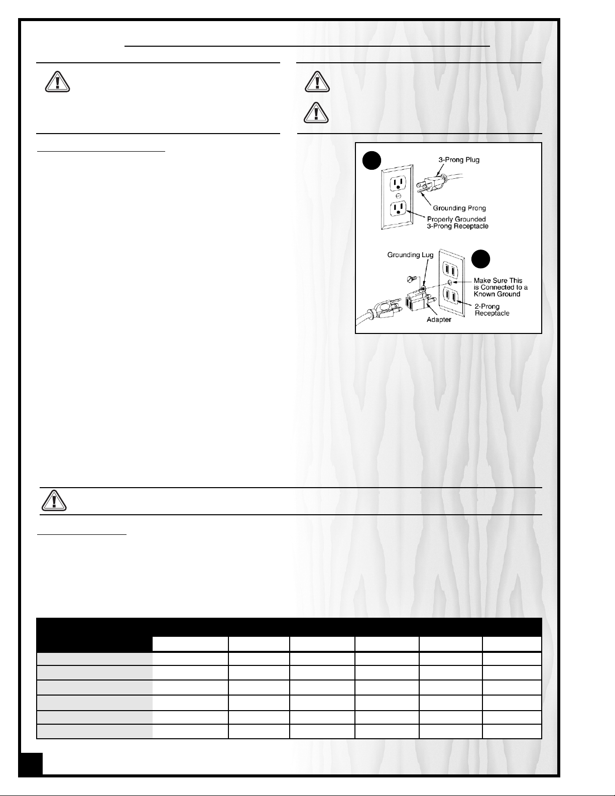
A
B
This tool is intended for use on a circuit that has an outlet that looks like the one illustrated in A. The tool has a
grounding plug that looks like the plug illustrated in A on the sketch above. A temporary adapter, which looks like
the adapter illustrated in B, may be used to connect this plug to a 2 pole receptacle if a properly grounded outlet
is not available. The temporary adapter should be used only until a properly grounded outlet can be installed by
a qualified electrician. This adapter is not permitted in Canada. The green-colored rigid ear, lug, and the like,
extending from the adapter must be connected to a permanent ground such as a properly grounded outlet box.
This tool must be grounded while in use to protect the operator from electrical shock.
EXTENSION CORDS:
RECEPTACLES THAT ACCEPT THE TOOL’S PLUG. REPAIR OR REPLACE DAMAGED OR WORN CORD IMMEDIATELY.
If you find it necessary to use an extension cord with your machine make sure the cord rating is suitable for the
amperage listed on the motor I.D. plate. An undersized cord will cause a drop in line voltage resulting in loss of
power and overheating. The accompanying chart shows the correct size extension cord to be used based on cord
length and motor I.D. plate amp rating. If in doubt, use the next heavier gauge. The smaller the number the
heavier the gauge.
AMPERES
(AMPS)
USE ONLY 3-WIRE EXTENSION CORDS THAT HAVE 3-PRONG GROUNDING PLUGS AND 3-POLE
EXTENSION CORD LENGTH
25 feet 50 feet 75 feet 100 feet 150 feet 200 feet
< 5 16 16 16 14 12 12
5 to 8 16 16 14 12 10 NR
8 to 12 14 14 12 10 NR NR
12 to 15 12 12 10 10 NR NR
15 to 20 10 10 10 NR NR NR
21 to 30 10 NR NR NR NR NR
* Based on limiting the line voltage drop to 5V at 150% of the rated amperes.
4
NR = Not Recommended
Page 5
VERTICAL OSCILLATING SPINDLE SANDER
15-220
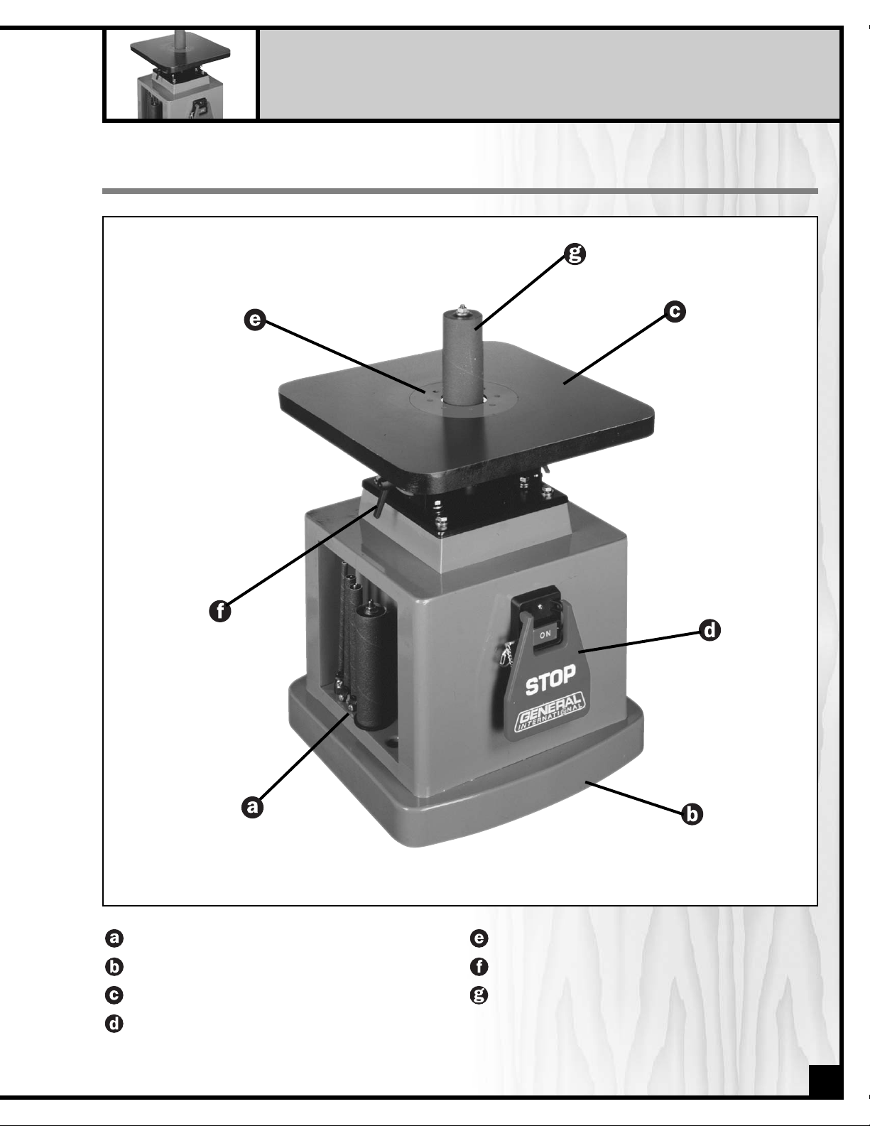
IDENTIFICATION OF MAIN PARTS AND COMPONENTS
ACCESSORY STORAGE
BASE
CAST-IRON TABLE
SWITCH ASSEMBLY
TABLE INSERT
TABLE TILT LOCK LEVER
SANDING SPINDLE
5
Page 6
UNPACKING AND SET-UP
UNPACKING
Carefully unpack and remove the unit and its components from its shipping container and check for missing or
damaged items as per the list of contents below.
NOTE: Please report any damaged or missing items to your GENERAL® INTERNATIONAL distributor immediately.
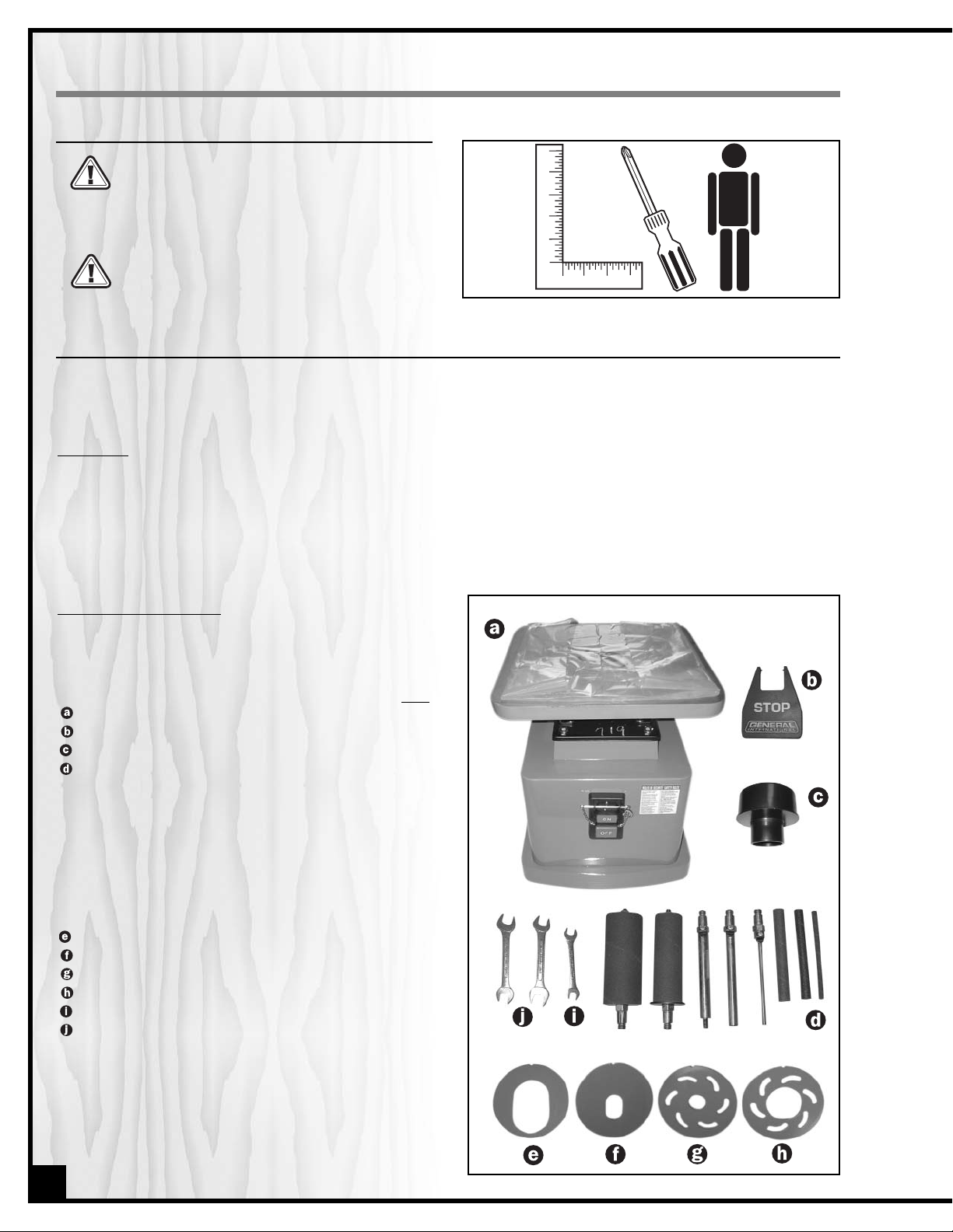
LIST OF CONTENTS
Separate and verify that all parts are in your accessories
hardware bags.
QTY
MACHINE . . . . . . . . . . . . . . . . . . . . . . . . . . . . . . . . . . .1
RED STOP COVER . . . . . . . . . . . . . . . . . . . . . . . . . . . .1
DUST HOSE ADAPTOR 2” TO 4” . . . . . . . . . . . . . . . . . .1
SANDING SPINDLE HARDWARE
— Sanding drum spindle assembly 1 1/2” . . . . . .1
— Sanding drum spindle assembly 2” . . . . . . . . .1
— Sanding sleeve 5/8” . . . . . . . . . . . . . . . . . . . . . . .1
— Sanding sleeve 1/2” . . . . . . . . . . . . . . . . . . . . . . .1
— Sanding sleeve 1/4” . . . . . . . . . . . . . . . . . . . . . . .1
— Spindle 5/8” . . . . . . . . . . . . . . . . . . . . . . . . . . . . . .1
— Spindle 1/2” . . . . . . . . . . . . . . . . . . . . . . . . . . . . . .1
— Spindle 1/4” . . . . . . . . . . . . . . . . . . . . . . . . . . . . . .1
TABLE INSERT 2”(oblong) . . . . . . . . . . . . . . . . . . . . . .1
TABLE INSERT 3/4” (oblong) . . . . . . . . . . . . . . . . . . . .1
TABLE INSERT 3/4”(round -*
Mounted on the machine) . . . . .1
TABLE INSERT 2” (round) . . . . . . . . . . . . . . . . . . . . . . .1
10-12 mm WRENCH . . . . . . . . . . . . . . . . . . . . . . . . . . .1
14-17 mm WRENCH . . . . . . . . . . . . . . . . . . . . . . . . . . .2
6
SET UP SAFETY
ADDITIONAL REQUIREMENTS FOR SET UP
• Machinists square
• Medium Phillips Screwdriver
• An extra person for help lifting
Serious personal injury could occur if you connect the machine to the power source before
you have completed the set up process. DO NOT
connect the machine to the power source until
instructed to do so.
The MODEL 15-220M1 is a heavy machine
(81 lbs shipping weight–37kg). Do not overexert. Arrange to have help nearby and ready
for unpacking and set up.
Page 7

ASSEMBLY INSTRUCTIONS
All unpainted surfaces are covered with a protective
coating that prevents rust from forming during shipping and
storage. Peel off the plastic cover from the table and remove
this protective coating by rubbing with a rag dipped in
kerosene, mineral spirits or paint thinner. (Dispose of potentially
flammable solvent-soaked rags according to manufacturer’s
safety recommendations.)
A putty knife, held flat to avoid scratching the surface, may also
be used to scrape off the coating followed by clean-up with
solvent. Avoid rubbing the machine’s painted surfaces,as many
solvent-based products will remove paint.
For optimum performance from your machine, make sure you
clean all metal surfaces of the spindles with a mild solvent or
kerosene.
To prevent rust, apply a light coating of paste wax or regular applications of General International “Top Saver” item
# GC-010 or similar after-market protectants to the table surface.
Be sure to work in a well ventilated area for the
entire clean up process.
Before starting the clean up process make sure the
machine is not plugged into a power source. Failure
to comply may lead injury or cause damage to the
machine.
CLEAN UP
The unit should be installed on a flat, sturdy and stable surface able to support the weight of the machine.
Never install the machine over the edge of a table
or workbench.
Never lift the machine by the table; hold and lift
from the insets on the cabinet.
Make sure that the switch is in “OFF”position and that the power
cord is unplugged & install the red stop switch cover plate.
7
Page 8

INST
ALL THE SANDING SLEEVES ONTO THEIR CORRESPONDING SPINDLES
Step 1
For 1/4, 1/2, & 5/8 spindles loosen the screw on the
bracket clamp ( ) at the bottom of the spindle.
Step 2
Slide the sanding sleeve onto the spindle completely.
Note: the sleeve should slide under the bracket
clamp as shown.
Re-tighten the screw on the bracket
clamp to secure the sleeve in place.
Step 3
Double check that the sleeve is now on the spindle
securely by pulling on the sleeve to make sure it does
not slide off the spindle.
Step 4
For the 1 1/2” and 2” spindles slide the sleeve onto the
spindle.
Step 5
Using the supplied 12 mm wrench tighten the nut on
the top of the spindle by turning counter clockwise
(reverse thread).
Step 6
Double check that the sleeve is now on the spindle
securely by pulling on the sleeve to make sure it does
not slide off the rubber drum. If the sleeve slides on
the drum, continue tightening the nut (step 5) in 1/2
turn increments as needed.
8
TIGHTEN
LOOSEN
Page 9

ACCESSORY STORAGE
SPINDLES
Place the drums into their storage space on the right
side of the machine.
TABLE INSERT PLATES
Store the table insert plates in the storage slots on the
left side of the machine.
INSTALLING SPINDLES ON THE MACHINE
If installed, remove the table insert to allow better
access the spindle seat.
Note: Reverse threads are used to attach the spindle to the machine.
Make sure that the switch is in “OFF” position and that the power cord is unplugged.
Step 1
Select the desired spindle and while holding the
spindle seat in place with a 17 mm wrench, screw the
threaded end into the spindle seat counter clockwise
(reverse threads) until hand tight.
TIGHTEN
LOOSEN
BEFORE STARTING THE MACHINE:
• Make sure the spindle is securely installed onto the arbor.
• Make sure that the corresponding table insert is installed. See the accompanying SELECTION GUIDE (page 10) to
select the correct INSERT TABLE for the spindle being used.
9
Step 2
Using the two 17 mm wrenches tighten the spindle no more than another 1/2 turn.
NOTE: Do not overtighten the spindle in the seat or it may be very difficult to take off later.
Page 10

10
SELECTION GUIDE FOR T
ABLE INSERTS
This machine is supplied with 5 spindles, and four table
inserts. The spindle diameters range from 1/4" to 2".
When changing spindles, the table insert will need to
be changed to the matching size. Each plate has
notch ( ) to fit the alignment pin ( ) in the table to
ensure that it is properly fitted and installed in the table
opening.
There are 2 insert plates with oblong openings and 2
with round openings. The oblong insert plates are
used when the table is tilted for bevel sanding.
The following chart explains which inserts can be used for different diameter spindles.
FAILURE TO USE THE PROPER INSERT WITH THE CORRESPONDING SPINDLE MAY RESULT IN INJURY AND/OR DAMAGE TO
THE MACHINE OR THE WORKPIECE.
SPINDLE DIAMETER TABLE INSERT (OPENING SHAPE/SIZE)
1/4” . . . . . . . . . . . . . . . . . . . . . . . . . . . . . . . . . . . . . . . . . . . . . . . . . . . . . . .#86 (ROUND) & #87 (OBLONG) -SMALL
1/2” . . . . . . . . . . . . . . . . . . . . . . . . . . . . . . . . . . . . . . . . . . . . . . . . . . . . . . .#86
(ROUND) & #87 (OBLONG) -SMALL
5/8” . . . . . . . . . . . . . . . . . . . . . . . . . . . . . . . . . . . . . . . . . . . . . . . . . . . . . .#86 (ROUND) & #87 (OBLONG) -SMALL
1-1/2” . . . . . . . . . . . . . . . . . . . . . . . . . . . . . . . . . . . . . . . . . . . . . . . . . . . . .#85 (ROUND) & #84 (OBLONG) -LARGE
2” . . . . . . . . . . . . . . . . . . . . . . . . . . . . . . . . . . . . . . . . . . . . . . . . . . . . . . . . .#85
(ROUND) & #84 (OBLONG) -LARGE
RECOMMENDED ADJUSTMENTS
Step 1
Loosen both locking levers, position the table at 0° and
re-tighten the locking levers.
Step 2
With a spindle installed, place a square on the table.
Rest the long section of the square against the
sanding spindle. The square should be flat against
the table and the spindle from all four sides.
SETUP FOR 90º SANDING
Page 11

Step 3
If the table needs adjustment loosen both lock levers
and readjust the table position until the square is flat
against the table and the sanding drum. To allow
for more or less rear tilt adjust the table stop rod as
needed.
Step 4
Make sure the pointer reads 0°. If the pointer needs
to be adjusted loosen the screw and adjust to the
correct position.
Step 5
Once the table has been adjusted and locked in place at 90° adjust the 90° table stop rod to butt against the underside of the table allowing you to return to 90° repeatedly without further adjustments.
SETUP FOR BEVEL SANDING
1. Make sure the correct oblong opening table insert is in
place. See the accompanying SELECTION GUIDE
(page 10) to select the correct TABLE INSERT for the
spindle being used.
2. Loosen both locking levers and tilt the table until the
pointer is at the desired angle.
3. Hold the table in place and tighten both locking levers.
CHANGING SANDING SLEEVES
Make sure that the switch is in “OFF” position and that the power cord is unplugged.
Note: Installing or changing sanding sleeves is best performed with the spindle removed from the machine.
Refer to page 8 - “Installing the sanding sleeves” for step by step instructions.
REPLACEMENT SANDING SLEEVES
Replacement sleeves can be purchased in varying grits (depending on availability) from any local tool or abrasives
dealer in the following sizes:
• 1/4" DIAMETER X 6 " LONG • 1-1/2" DIAMETER X 5 1/2 " LONG
• 1/2" DIAMETER X 6 " LONG • 2” DIAMETER X 5.5” LONG
• 5/8" DIAMETER X 6 " LONG
11
90° TABLE
STOP ROD
Page 12

CONNECT TO A DUST COLLECTOR
Before sanding connect the machine to a dust
collection system.
• There is a 2” diameter dust outlet on the rear of the machine
allowing for the connection to a dust collector
• A 2” TO 4” DUST HOSE ADAPTOR is also included to facilitate
(if needed) connection to a standard 4” dust collection
hose.
• Be sure to use appropriate size hose and fittings
and check that all connections are sealed tightly to minimize airborne dust.
• If you do not already own a dust collection system consider contacting your GENERAL® INTERNATIONAL distributor
for information on our complete line of dust collection
systems or visit our Web Site at: www.general.ca
(not included).
(not included).
Always turn on the dust collector before starting the
sander and always stop the sander before turning
off the dust collector.
OPERATING INSTRUCTIONS
BASICFUNCTIONS OF THIS MACHINE
This machine has been designed for sanding or polishing round or curved surfaces on wood, plastic, or metal
materials.It is ideal for use in smaller woodworking projects in a hobbyist/home shop environment.This machine is not
designed with a continuous duty rating or for industrial applications.
CONNECTING TO A POWERSOURCE
Plug the machine into a proper receptacle – before connecting to the power source make sure that the switch is in
the “off” position and that the power supply is of the same type as that stamped on the I.D. nameplate of the motor.
Running on low voltage will damage the motor.
To avoid risk of shock or fire do not operate the unit with a damaged power cord or plug. Replace damaged cord
or plug immediately.
ON/OFFSWITCH SAFETYPIN
The switch assembly is equipped with a lock-out safety pin. When the
pin is installed through the green “on” button, the machine cannot be
started.
To start the machine, lift the red stop switch panel and remove the lockout pin. Lower the stop panel and push the green “ON” button. Wait for
the spindle to reach full speed before sanding.
To stop the machine, push on the RED “STOP” panel and wait for the
spindle to come to a complete stop.
When you have finished using the machine be sure to re-install the lockout pin and unplug the machine from the power source.
PADLOCK
To avoid accidental manipulation by young children or others not
qualified, the use of a padlock is required.
To lock out the ON/OFF witch, just open the padlock ( ), insert it
through the “Start button” hole ( ) and simply close the padlock.
Place the key in a safe place out of the reach of children.
12
Page 13

BASICOPERATIONS
Before operating this machine, make sure you
have read this manual attentively! Failure to read
and understand the instructions, warnings and safety guidelines provided in this manual may lead to
serious injury and / or damage to machine or the
workpiece.
Make sure the table tilt locking levers are secured
and that the table is locked in place at the desired
angle or tilt.
Be sure the sanding spindle is securely installed in
the machine.
Make sure the machine is installed on a flat, sturdy
and stable surface able to support the weight of the
machine and the workpiece to be sanded.
Maintain 1.6 mm clearance between table and
sanding belt.
1. Select and install a spindle that is smaller than the curve to be sanded.
2. Use an appropriate table insert plate that comes closest to the spindle without touching it.
3. Make sure that spindle is properly installed in the spindle seat. With the supplied wrenches tighten the nut
slightly beyond hand-tight.
NOTE: Spindle threads are reversed. Turn Clockwise to loosen and counter clockwise to tighten.
NOTE: Never over tighten; it may be difficult to remove the spindle later.
4. When table is set at a 90° angle, sanding may be done
from any corner, or location on the table.
5. When the table is positioned at any angle other than 90°,
sanding should only be performed with the workpiece
positioned below the centre point of the table (photo)
ok
ok
ok
ok
6. Make sure the table tilt locking levers are secured and that
the table is locked in place at the desired angle or tilt.
7. Always loosen both table tilt locking levers before changing the angle position of the table. Never force the
table. If it does not tilt easily it may be that the locking levers may still be engaged.
8. Hold the workpiece firmly and work from a stable standing position.
9. To achieve the best finish results and to ensure maximum sanding sleeve life, slowly move the workpiece back
and forth across the entire surface of the sanding spindle.
MAINTENANCE
Make sure the switch is in the OFF position and unplug the unit from the power source before performing any
maintenance.
• All bearings are sealed and permanently lubricated. No further lubrication is needed.
• Periodically inspect all hardware, fittings and fasteners that may have loosened due to vibration – re-tighten as
needed.
• To minimize airborne dust particles periodically inspect all dust collection fittings – re-tighten as needed.
• Inspect the ON/OFF SWITCH for damage before each use.
• Keep the machine CLEAN and FREE OF DUST to help dissipate heat.
• Check and if necessary replace all damaged TABLE INSERTS, SPINDLES or SANDING SLEEVES
• Periodically inspect the power cord and plug for damage. If necessary replace the power cord and the plug at
the first signs of visible damage.
• Use only recommended parts and accessories. The use of parts or accessories NOT recommended by General
International may result in a risk of injury or damage to the machine.
13
Page 14

RECOMMENDED OPTIONAL
ACCESSORIES FOR YOUR
OSCILLATING SPINDLE SANDER
We offer a large variety of products to help you increase productivity, accuracy and safety when using your oscillating spindle sander. Here’s a small sampling of accessories available
from your local General International dealer.
Dust Collector
We have a wide selection
of dust collectors to suit all
your shop needs. Dust
collectors contribute
to a cleaner and more
healthful workshop
environment.
“TOP SAVER”
cleaner #GC-010
All in one, table top rust
remover and lubricant.
/Reduces friction and prevents binding. / Removes
and inhibits rust and
corrosion. /Repels dust
and moisture.
14
Stand
#15-230
ITEM # DECRIPTION
15-211A Sanding Sleeve 1/4" X 6" 40 Grit
15-211B Sanding Sleeve 1/4" X 6" 60 Grit
15-211C Sanding Sleeve 1/4" X 6" 80 Grit
15-211D Sanding Sleeve 1/4" X 6" 100 Grit
15-211E Sanding Sleeve 1/4" X 6" 120 Grit
15-211F Sanding Sleeve 1/4" X 6" 150 Grit
15-212A Sanding Sleeve 1/2" X 6" 40 Grit
15-212B Sanding Sleeve 1/2" X 6" 60 Grit
15-212C Sanding Sleeve 1/2" X 6" 80 Grit
15-212D Sanding Sleeve 1/2" X 6" 100 Grit
15-212E Sanding Sleeve 1/2" X 6" 120 Grit
15-212F Sanding Sleeve 1/2" X 6" 150 Grit
15-213A Sanding Sleeve 5/8" X 6" 40 Grit
15-213B Sanding Sleeve 5/8" X 6" 60 Grit
15-213C Sanding Sleeve 5/8" X 6" 80 Grit
15-213D Sanding Sleeve 5/8" X 6" 100 Grit
15-213E Sanding Sleeve 5/8" X 6" 120 Grit
15-213F Sanding Sleeve 5/8" X 6" 150 Grit
15-214A Sanding Sleeve 1 1/2" X 5 1/2 40 Grit
15-214B Sanding Sleeve 1 1/2" X 5 1/2 60 Grit
15-214C Sanding Sleeve 1 1/2" X 5 1/2 80 Grit
15-214D Sanding Sleeve 1 1/2" X 5 1/2 100 Grit
15-214E Sanding Sleeve 1 1/2" X 5 1/2 120 Grit
15-214F Sanding Sleeve 1 1/2" X 5 1/2 150 Grit
15-215A Sanding Sleeve 2" X 5 1/2" 40 Grit
15-215B Sanding Sleeve 2" X 5 1/2" 60 Grit
15-215C Sanding Sleeve 2" X 5 1/2" 80 Grit
15-215D Sanding Sleeve 2" X 5 1/2" 100 Grit
15-215E Sanding Sleeve 2" X 5 1/2" 120 Grit
15-215F Sanding Sleeve 2" X 5 1/2" 150 Grit
Page 15

15
Modèle #15-220
Page 16

16
PARTS LIST
15-220
PART N0. REF. N0. DESCRIPTION SPECIFICATION QTY
15220-01 30201001G BASE 1
15220-02 30201001A TOP PLATE 1
15220-03 S1006P1 STRAIN RELIEF 1
15220-04 L0000000 POWER CORD (W/PLUG) 1
15220-05 S0030622M PHILLIPS HEAD SCREW M6 X 1 X 22L 4
15220-06 10107098 RUBBER FOOT 4
15220-07 S0210400 WASHER 1/4" X 19MM 6
15220-08 S0110600M LOCK NUT M6X1.0 4
15220-09 S0230300 LOCK WASHER 3/16" 2
15220-10 S0030318 PHILLIPS HEAD SCREW 3/16"-24UNC X 3/4" 2
15220-11 M0000000 MOTOR 1
15220-12 S0430650 KEY 6 X 6 X 50 1
15220 -13 S0040415M SET SCREW M4 X 0.7 X 15L 2
15220-14 30202001 WORM GEAR 1
15220-15 S0050610M SET SCREW M6 X 1.0 X 10L 2
15220-16 30202002 TRANSMISSION ROD M8 X 1.25 X 75L 1
15220-17 S0110800M HEX. NUT M8 X 1.25 1
15220-18 30202003 CONNECTING ROD 2
15220-19 S0210400 WASHER 1/4" X 19MM 4
15220-20 S012500M HEX NUT M5 2
15220-21 C1106804 BEARING 6804ZZ 1
15220-22 30202004 SPINDLE SEAT 1
15220-23 CL106006 BEARING 6006ZZ 1
15220-24 S0520059 RETAINING RING- C TYPE 1
15220-25 30202005 CONNECTING ROD NUT 4
15220-26 S0050506M SET SCREW M5 X 0.8 X 6L 2
15220-27 S05ETW04 RETAINING RING-E TYPE 2
15220-28 30202020 CONNECTING SPINDLE 1
15220-29 30202006P WHEEL SEAT 1
15220-30 30202007P WHEEL 1
15220-31 S0010615M SET SCREW M6 X 1.0 X 10L 4
15220-32 30202008P WHEEL ARBOR 1
15220-33 30204010 ARBOR COVER 2
15220-34 S0230400 LOCK WASHER 1/4" 4
15220-35 S0400415 KEY 4 X 4 X 15 1
15220-36 CL106001 BEARING 6001ZZ 2
15220-37 S0521200 RETAINING RING C-TYPE STW-12 2
15220-38 S0530028 RETAINING RING C-TYPE R-28 2
15220-39 S0230506 LOCK WASHER 5/16" 11
15220-40 S0210500C FLAT WASHER 5/16" X 18 X 2T 11
15220-41 30202009 OIL CAP 1
15220-42 30202014 REAR OIL CAP 1
15220-43 S0030304 PHILLIPS HEAD SCREW 3/16"-24UNC X 1/4" 2
15220-44 30203001 MAIN CASTING 1
15220-45 30203003 L BRACKET (RIGHT) 1
15220-46 30203003A L BRACKET (LEFT) 1
15220-47 S0020825M CAP SCREW M8 X 1.25 X 20L 11
15220-48 30300028 90° TABLE STOP ROD M8 X 1.25 X 110L 1
15220-49 S0110600 HEX NUT M8 1
15220-50 40501011 TABLE TILT GUIDE BRACKET WITH SCALE (RIGHT) 1
Page 17

17
PARTS LIST
15-220
PART N0. REF. N0. DESCRIPTION SPECIFICATION QTY
15220-51 40501011A TABLE TILT GUIDE BRACKET (LEFT) 1
15220-52 30204013G LOCKING LEVER 2
15220-53 S0010516M PHILLIPS HEAD SCREW 4
15220-54 S0050606M SET SCREW M6 X 1.0 X 6L 1
15220-55 10102022 ANGLE POINTER 1
15220-56 S0220400 SPROCKET WASHER 1/4" 1
15220-57 S0030510M PHILLIPS HEAD SCREW M5 X 0.8-10L 1
15220-58 30203005 DUST PORT 1
15220-60 30203006 SPINDLE 22 X 119 1
15220-61 30203007 COVER 1
15220-62 S0030508M SET SCREW M5 X 0.8-8L 2
15220-63 S0520028 SNAP RING 1
15220-64 30203008 5/8” SPINDLE 2
15220-64A 30203008G 5/8” SPINDLE 1
15220-65 S0400550 KEY 5 X 5 X 50 1
15220-66 30203015 DRUM 2" 1
15220-67 30203014 DRUM 1-1/2" 1
15220-68 30203017 1/2" SPINDLE 1
15220-69 30203018 1/4" SPINDLE 1
15220-70 30203019 1/2" CLAMP 1
15220-71* SEE LIST ON PG. 14 FOR OPTIONAL/REPLACEMENT SANDING SLEEVES
15220-72* SEE LIST ON PG. 14 FOR OPTIONAL/REPLACEMENT SANDING SLEEVES
15220-73* SEE LIST ON PG. 14 FOR OPTIONAL/REPLACEMENT SANDING SLEEVES
15220-74* SEE LIST ON PG. 14 FOR OPTIONAL/REPLACEMENT SANDING SLEEVES
15220-75* SEE LIST ON PG. 14 FOR OPTIONAL/REPLACEMENT SANDING SLEEVES
15220-76 30203019A 5/8" CLAMP 1
15220-77 30203019B 1/4" CLAMP 1
15220-78 30204001 MAIN TABLE 1
15220-79 20301002 LOWER FOLLOWER PLATE 1-1/2" & 2” 2
15220-80 20801002 UPPER FOLLOWER PLATE 1-1/2" 1
15220-81 20301044 UPPER FOLLOWER PLATE 2" 1
15220-82 S02 10500 WASHER 5/16" X16 2
15220-83 S0110500 5/16" NUT (LH) 2
15220-84 30204003 TABLE INSERT (OBLONG) 2" 1
15220-85 30204004 TABLE INSERT (ROUND) 2" 1
15220-86 30204005 TABLE INSERT (ROUND) 3/4" 1
15220-87 30204006 TABLE INSERT (OBLONG) 3/4" 1
15220-88 S0310312 ALIGNMENT SPRING PIN 3 X 12M/M 1
15220-89 30201003 COMBINATION WRENCH 14/17MM
(NOT SHOWN)
2
15220-90 10105091 COMBINATION WRENCH 10/12
(NOT SHOWN)
1
15220-91 J8010004 WARNING LABEL
(NOT SHOWN)
1
15220-92 J2091001 I.D LABEL
(NOT SHOWN)
1
15220-93 WG000001 SWITCH ASSEMBLY W/ COVER PLATE 1
15220-94 RED STOP SWITCH COVER PLATE 1
15220-95 WG000002 SWITCH BOX 1
15220-96 WG000003 SAFETY LOCK-OUT PIN W/CHAIN 1
15220-97 2” TO 4” DUST HOSE ADAPTOR 1
Page 18

IMPORTANT: When ordering replacement parts, always give the model number, serial number of
the machine and part number. Also a brief description of each item and quantity
desired.
15-220
8360 Champ-d’Eau, Montreal (Quebec)
Canada H1P 1Y3
Tel.: (514) 326-1161
Fax : (514) 326-5565
Parts & Service
Fax : (514) 326-5555 Order Desk
orderdesk@general.ca
www.general.ca
 Loading...