

Page 1

Heavy-duty enclosed stand for
reater stability.
g
Sanding belt operates at any angle
from horizontal to vertical.
ccurate belt tension and tracking
A
djustment.
a
Cast-iron table can be adjusted up
or down for full belt use.
Conveniently mounted motor
controls.
Cast-iron miter gauge can be locked
in position for quick and easy setup.
Adjustable, removable front table
fence.
Graphite covered steel plate for
reduced friction and extended
belt life.
LENGTH OF OSCILLA
TION
UP: 1/8’’ (3.2 mm)
DOWN: 1/8’’ (3.2 mm)
TOTAL: 1/4’’ (6.4 mm)
T SIZE
BEL
6’’ x 89’’ (152 x 2260 mm)
T SPEED
BEL
3900 LIN. FPM (1279 LIN. MPM)
AREA
LENGTH OF
W
ORK
33 3⁄4” (857 mm)
DUST CHUTE OUTLET
(102 mm)
4”
FRONT
TABLE SIZE
9 7⁄8” x 29 5⁄8” (250 x 751 mm)
UXILIARY/END TABLE SIZE
A
9 7⁄8” x 11 7⁄8” (250 x 300 mm)
ASE DIMENSIONS (L x W)
B
21 1/2” x 17” (546 x 432 mm)
VERALL DIMENSIONS (L x W x H)
O
50” x 21” x 49” (1270 x 533 x 1245 mm)
MO
TOR - PRE-WIRED 220V
110/220
,
2 HP
⁄
1 1
V
18/9
,
A
WEIGHT
277 LBS (126 kg)
REVISION 1 - OCTOBER 26/07
© COPYRIGHT GENERAL INTERNA
TIONAL 10/2007
Page 2

GENERAL® INTERNATIONAL
8360 Champ-d’Eau, Montreal (Quebec) Canada H1P 1Y3
Telephone (514) 326-1161 • Fax (514) 326-5555 • www.general.ca
THANK YOU for choosing this General® International model 15-005S 6” x 89”
oscilla
ment and if pr
ting edge belt sander. This sander has been car
operly used and maintained,
will provide you with years of reliable service. To
ensure optimum performance and trouble-free operation, and to get the most from your
tment, please tak
inves
e the time to r
ead this manual befor
ating the unit.
efully tested and inspected before ship-
e assembling, installing and oper-
The man
ual’s purpose is to familiarize you with the safe operation, basic function, and features
of this edge belt sander as well as the set-up, maintenance and identification of its parts and
components. This manual is not intended as a substitute for formal woodworking instruction,
nor to offer the user ins
uction in the craft of w
tr
oodworking. If you are not sure about the safety of performing a certain operation or procedure, do not proceed until you can confirm, from
knowledgeable and qualified sources, that it is safe to do so.
ve read through these instructions, keep this manual handy for future reference.
Once y
ou’
GENERAL ® INTERNATIONAL WARRANTY
All component par
production, and each machine is thoroughly inspected upon completion of assembly. Because of our commitment to quality and customer satisfaction, General® International agrees to repair or replace, within a period of 24
months from da
manship or material. In order to obtain this warranty, all defective parts must be returned freight pre-paid to
General® International Mfg. Co., Ltd. Repairs attempted without our written authorization will void this warranty.
Disclaimer: The inf
the unit as it was supplied from the factory at the time of printing.
Because we are committed to making constant improvements, General
International reserves the right to make changes to components, parts
or features of this unit as deemed necessary, without prior notice and
without obligation to install any such changes on previously delivered
Reasona
.
units
cations and information in this manual corresponds with that of the unit
with which it was supplied. However, special orders and “after factory”
ble car
ts of General® Inter
te of purchase, any genuine part or parts which, upon examination, prove to be defective in work-
tion and specifications in this manual pertain to
ma
or
actory to ensure that the specifi-
t the f
en a
e is tak
national machiner
y are car
modif
inapplicable to your machine. Further, as several generations of this
model of sander and several versions of this manual may be in circulation, if you own an earlier or later version of this unit, this manual may not
depict your machine exactly. If you have any doubts or questions
contact your retailer or our support line with the model and serial number of y
efully tested and inspected during all stages of
tions may r
ica
our unit f
ender some or all information in this manual
tion.
ica
if
or clar
Page 3

Rules for Safe Operation
To help ensure safe operation, please take a moment to learn the machine’s applications and limita-
ions, as well as potential hazards. General® International disclaims any real or implied warranty and
t
olds itself harmless for any injury that may result from improper use of its equipment.
h
1. Do not operate the sander when tired, distracted, or
under the effects of drugs, alcohol or any medica-
ion that impairs reflexes or alertness.
t
2. The working area should be well lit, clean and free
of debris.
3. Keep children and visitors at a safe distance when
the sander is in operation; do not permit them to
operate the sander.
4. Childproof and tamper proof your shop and all
machinery with locks, master electrical switches
and switch keys, to prevent unauthorized or unsupervised use.
5. Stay alert! Give your work your undivided attention.
Even a momentary distraction can lead to serious
injury.
6. Fine particulate dust is a carcinogen that can be
hazardous to health. Work in a well-ventilated area
and whenever possible use a dust collector and
wear eye, ear and respiratory protection devices.
7. Do not wear loose clothing, gloves, bracelets, neck-
hile the sander is in opera-
y w
laces or other jew
tion.
8. Be sure that adjusting wrenches, tools, drinks and
other clutter are removed from the machine and/or
the table surface before operating.
elr
12. Do not push or force the work piece into the sander.
The machine will perform better and more safely
hen working at the feed rate for which it was
w
designed.
13. Avoid working from awkward or off balance positions. Do not overreach and keep both feet on floor.
14. Keep guards in place and in working order. If a
guard must be removed for maintenance or cleaning, be sure it is properly re-attached before using
the tool again.
15. Never leave the machine unattended while it is running or with the power on.
16. Use of parts and accessories NOT recommended
by General
ment malfunction or risk of injury.
17. Never stand on tool.Serious injury could occur if the
tool is tipped over or if the sanding belt is unintentionally contacted.
18. Always disconnect the tool from the power source
before servicing, changing accessories or the
sanding belt, or bef
nance or cleaning, or if the machine will be left
unattended.
19. Make sure that switch is in "OFF" position before
plugging in the power cord.
® International may result in equip-
e performing any mainte-
or
9. Keep hands well away from the sanding belt and
all moving parts. Use a brush, not hands, to clear
away chips and dust.
10. Be sure sanding belts are securely installed in the
machine.
11. Do not operate the sander if the sand paper is
damaged or badly worn.
20. Make sure the tool is properly grounded. If
equipped with a 3-prong plug it should be used
with a three-pole receptacle. Never remove the
third prong.
21. Do not use this sander for other than its intended
use. If used for other purposes, General
International disclaims any real implied warranty
and holds itself harmless for any injury, which may
result from that use.
®
Page 4

ELECTRICAL REQUIREMENTS
SERIOUS PERSONAL INJURY COULD OCCUR IF YOU CONNECT THE MACHINE TO THE POWER SOURCE BEFORE
COMPLETING THE SET-UP AND ASSEMBLY PROCESS. DO NOT PLUG THE MACHINE INTO A POWER SOURCE UNTIL
INSTRUCTED TO DO SO.
Plug the sander into a proper receptacle. Your power tools should be connected to a dedicated electrical circuit
of not less than #14 wire and should be protected with a 15 amp time lag fuse. If an extension cord is needed use
only 3 wire cords with 3-prong grounded type plugs and 3-pole receptacles. Consult the chart below for details on
electing an extension cord.
s
TABLE - MINIMUM GAUGE FOR CORD
AMPERE
RA
ORE
M
THAN
0
6
10
12
TING
NOT
M
ORE
THAN
6
10
12
16
BEFORE CONNECTING THE SANDER TO A POWER SOURCE, MAKE SURE THAT THE ELECTRICAL CURRENT IS OF THE
SAME TYPE AS THAT STAMPED ON THE MOTOR NAMEPLATE. ALL ELECTRICAL CONNECTIONS SHOULD HAVE A PROPER CONTACT. NEVER CONNECT THE MACHINE TO A POWER SOURCE OF GREATER OR LOWER VOLTAGE THAN NEEDED. FAILURE TO COMPLY COULD RESULT IN SERIOUS INJURY TO THE USER AND/OR DAMAGE TO THE MACHINE. IF IN
DOUBT, CONTACT A QUALIFIED ELECTRICIAN BEFORE CONNECTING TO THE POWER SOURCE.
VOLTS
110 V
220 V
2
5 ft.
50 ft.
18
18
16
14
TOTAL LENGTH OF CORD IN FEET
5
0 ft.
100 ft.
AWG
16
16
16
12
GROUNDING
This sander must be grounded to protect the operator from electrical shock. The
supplied motor for this sander is pre-wired for 220V, single phase operation and has
a 3-conductor cord and 3-prong grounded plug to fit a grounded-type recepta-
.
cle
1
00 ft.
200 ft.
16
14
14
-
1
50 ft.
300 ft.
14
12
12
-
CONVERTING THE MOTOR TO 110V
Should y
the inside of the motor cover plate. Unless you are a qualified electrician, we do not recommend attempting this conversion on your own. If you choose to do so, you may risk serious personal injury, damage to the motor and voiding the warranty of your machine.
We suggest you ask your local General International distributor to recommend qualified electricians in your area
(or perhaps one of their own technicians) who can make this conversion properly and safely.
ou need to convert your machine’s motor from 220V to 110V power, there is an electrical schematic drawing on
4
Page 5
6” X 89” OSCILLATING EDGE BELT SANDER
15-005S
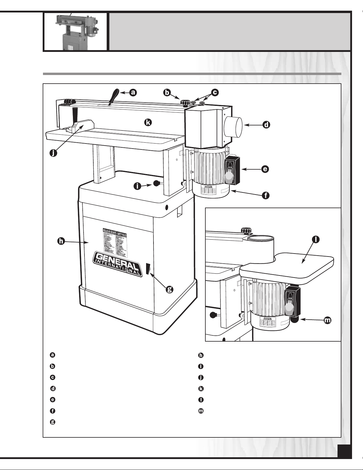
IDENTIFICATION OF MAIN PARTS AND COMPONENTS
BELT TENSION LEVER
LOCK KNOB
DUST HOOD LOCK KNOB
DUST OUTLET
SAFETY
MOTOR
ASE
B
SWITCH
DOOR HANDLE
ASSEMBLY
DOOR
ADJUSTMENT LEVER
T
SANDING HEAD
MITER GAUGE
SANDING BELT
UXILIAR
A
AUXILIARY/END TABLE SUPPORT ROD
Y/END TABLE
TIL
5
Page 6
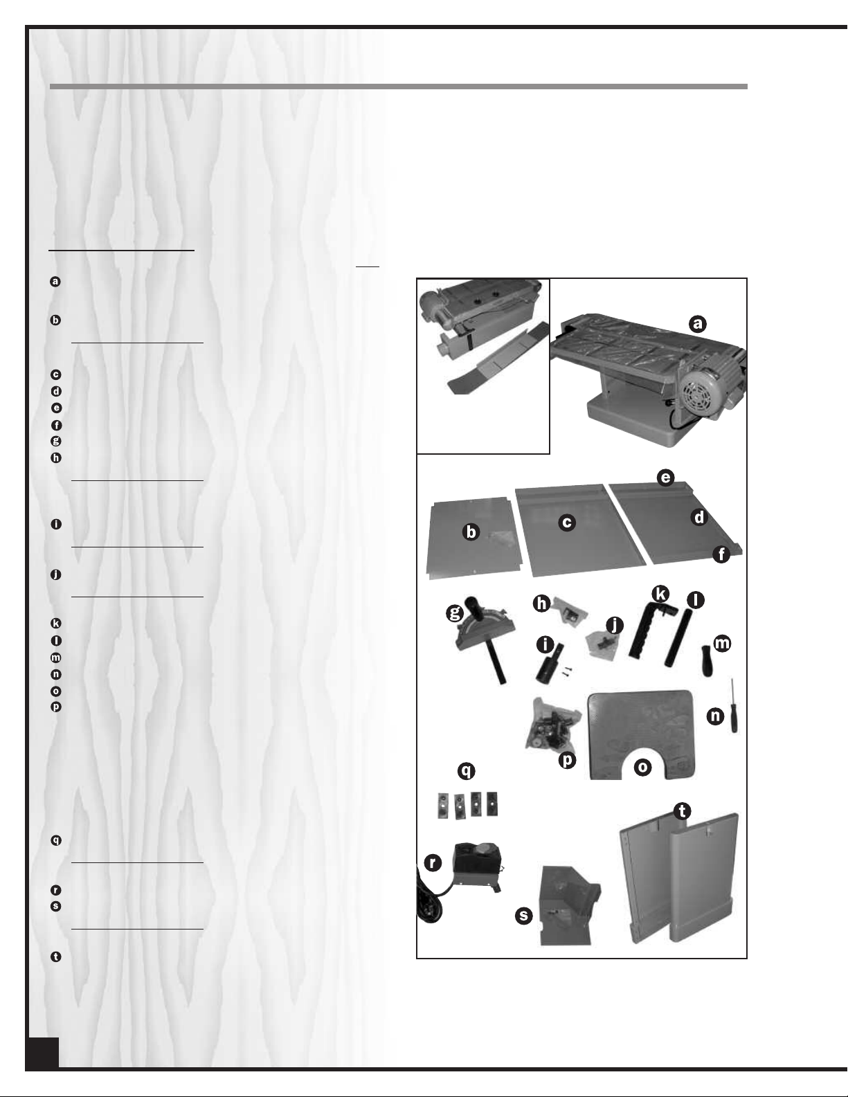
UNPACKING
arefully unpack and remove the unit and its components from its shipping container and check for missing or
C
damaged items as per the list of contents below.
NOTE: Please report any damaged or missing items to your GENERAL® INTERNATIONAL distributor immediately.
LIST OF CONTENTS
QTY
SANDING HEAD . . . . . . . . . . . . . . . . . . . . . . . . . . . . . . . .1
-FENCE*, 6” X 89” 100 GRIT SANDING BELT* . . . . . . . . . . . . . .1
SHELF . . . . . . . . . . . . . . . . . . . . . . . . . . . . . . . . . . . . . . . . .1
HARDWARE BAG INCLUDING:
— PHILLIPS SCREW, FLAT WASHER , LOCK WASHER . . . . . . . . . . . . . . .2
BACK PANEL . . . . . . . . . . . . . . . . . . . . . . . . . . . . . . . . . . .1
DOOR . . . . . . . . . . . . . . . . . . . . . . . . . . . . . . . . . . . . . . . .1
UPPER DOOR SUPPORT RAIL . . . . . . . . . . . . . . . . . . . . . .1
LOWER DOOR SUPPORT RAIL . . . . . . . . . . . . . . . . . . . . .1
MITER GAUGE . . . . . . . . . . . . . . . . . . . . . . . . . . . . . . . . . .1
DOOR STOPPER
HARDWARE BAG INCLUDING:
— STOPPER . . . . . . . . . . . . . . . . . . . . . . . . . . . . . . . . . . . . . . . . . . . . . .1
— PHILLIPS SCREW . . . . . . . . . . . . . . . . . . . . . . . . . . . . . . . . . . . . . . . .2
TABLE SUPPORT BRACKET . . . . . . . . . . . . . . . . . . . . . . . . .1
HARDWARE BAG INCLUDING:
— SCREW . . . . . . . . . . . . . . . . . . . . . . . . . . . . . . . . . . . . . . . . . . . . . . .2
DOOR HANDLE
HARDWARE BAG INCLUDING:
— HANDLE, RUBBER STOPPER, FLAT WASHER, LOCK NUT . . . . . . . . . .1
WORKPIECE STOP . . . . . . . . . . . . . . . . . . . . . . . . . . . . . .1
TABLE ROD . . . . . . . . . . . . . . . . . . . . . . . . . . . . . . . . . . . .1
TENSION LEVER HANDLE . . . . . . . . . . . . . . . . . . . . . . . . . .1
DRUM ADJUSTMENT TOOL . . . . . . . . . . . . . . . . . . . . . . .1
AUXILIARY/END TABLE . . . . . . . . . . . . . . . . . . . . . . . . . . .1
WARE BAG . . . . . . . . . . . . . . . . . . . . . . . . . . . . . . . .1
HARD
. . . . . . . . . . . . . . . . . . . . . . . . . . . . . . . . . . . . . . . . . . . . . . .1
HANDLE
—
-LOCK KNOB (SHORT TOGGLE SCREW) . . . . . . . . . . . . . .2
LOCK KNOB (MEDIUM & LONG TOGGLE SCREW) . . . . . .1
-
ASHER (LARGE) . . . . . . . . . . . . . . . . . . . . . . . . . . . . . . . . . . .5
W
T
FLA
—
— FLAT WASHER (MEDIUM), LOCK WASHER . . . . . . . . . . . . . . . . . .14
— CARRIAGE BOLT, HEX NUT . . . . . . . . . . . . . . . . . . . . . . . . . . . . . .12
HEX BOL
—
T (LONG)
. . . . . . . . . . . . . . . . . . . . . . . . . . . . . . . . . . . . .
RUBBER FEET . . . . . . . . . . . . . . . . . . . . . . . . . . . . . . . . . . .4
HARDWARE BAG INCLUDING:
BOLT, NUT . . . . . . . . . . . . . . . . . . . . . . . . . . . . . . . . . .4
ASHER,
W
T
— FLA
SAFETY SWITCH ASSEMBLY . . . . . . . . . . . . . . . . . . . . . . . .1
RIGHT DRUM GUARD . . . . . . . . . . . . . . . . . . . . . . . . . . .1
AG INCLUDING:
WARE B
HARD
— FLANGE SCREW . . . . . . . . . . . . . . . . . . . . . . . . . . . . . . . . . . . . . . . .3
SIDE PANEL . . . . . . . . . . . . . . . . . . . . . . . . . . . . . . . . . . .2
2
*The sanding belt and the
ence are stored inside the
f
sanding head to prevent
damage in shipping.
6
Page 7
PREPARATION AND PLACEMENT WITHIN THE SHOP
50”
21 1/2”
17”
21”
49”
SET UP SAFETY
Serious personal injury could occur if you connect
the machine to the power source before you have
completed the set up process. DO NOT connect
the machine to the power source until instructed to
do so.
The MODEL 15-005S is a heavy machine (277 LBS 126 kg). Do not over-exert. Arrange to have help
nearby and ready for unpacking and set- up.
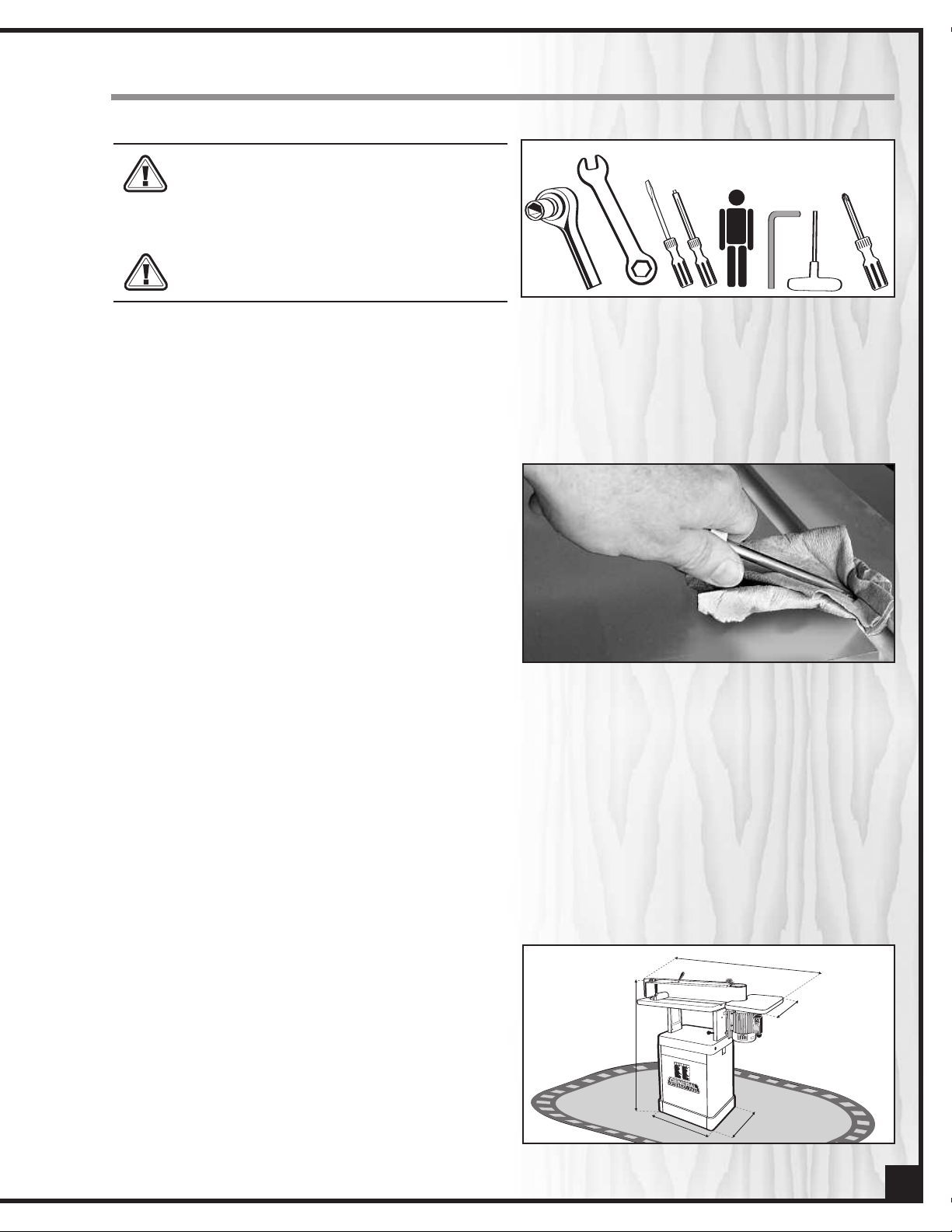
CLEAN UP
The unpainted cast-iron surface of the tables are covered
with a protective coating that helps prevent rust from
forming during shipping and storage. Remove this protective coating by rubbing with a rag dipped in kerosene,
mineral spirits or paint thinner.
tially flammable solvent soaked rags according to manufacturers’ safety recommendations.) A putty knife, held flat to avoid
scratching the surface, may also be used to scrape off the
coating followed by clean-up with solvent. Avoid rubbing
the painted surfaces, as many solvent based products will
remove paint.
To prevent rust, apply a light coating of paste wax or use
regular applications of any after-market surface protectant or rust inhibitor such as General International “Top
Saver” item #GC-010.
(Handle and dispose of poten-
ADDITIONAL REQUIREMENTS FOR SET UP
OROR
• 12 mm Hex socket or 12 mm Open end wrench
• Flat head screwdriver
• Small square head screwdriver
• Extra person for help with lifting
• 4 mm Allen key or 4 mm T-handle hex wrench
• Phillips screwdriver
Tip/Hint: With a screw driver, push a solvent-saturated rag into the
T-slot to remove the grease so the miter gauge will slide freely.
PLACEMENT WITHIN THE SHOP
This model 10-005S MI should be installed and operated only on a solid, flat and stable floor that is able to support
the weight of the sander (277 LBS -126 kg) and the operator. Using the dimensions shown as a guideline, plan for
placement within y
(either passing shop visitors or other shop workers) or other tools or machinery.
our shop that will allo
w the operator to w
k unencumbered and unobs
or
tructed by foot traffic
ESTABLISHING A SAFETY ZONE
For shops with fr
advisable to establish a Safety Zone around shop
machinery. A clearly defined “no-go” zone on the floor
around each machine can help avoid accidents that
could cause injury to either the operator or the shop visitor. It is advisable to take a few moments to either paint
(using non-slip paint) or using tape, define on the floor the
limits or perimeter of each machines safety zone. Take
teps to ensur
s
e that these areas are off limits whenever a machine
ar
aw
is running for everyone but the individual operating the
unit.
equent visitor
e tha
t all opera
s or multiple operators, it is
s and shop visitors are
tor
7
Page 8

ASSEMBLY INSTRUCTIONS
ASSEMBLE THE BASE
b
w
n
olt
asher
ut
rubber
f
oot
1. Using a bolt, washer, and a nut, attach 2 rubber
feet to the side panels (2) according to
order of assembly . Tighten nuts with either a 12
mm hex socket or 12 mm Allen key.
DOOR
stopper
w
asher
ut
n
3. Install the door handle on the door by following the order illustrated in figure .Install the door
between both door supports, first by inserting the
rod into the hole of the lower door support ,
then, by pulling down on the spring lever , and
placing it in the hole of the upper door support.
2. Attach the upper and lower door supports to
the side panels , shown above, using the carriage bolts, medium flat washers, lock washers and
nuts.
Note: Make sure the hole in the upper door support
faces downward , and the hole in the lower door
support faces upward (so that the table rod can be
inserted into the lower door support and the spring
lever can be inserted into the upper door support.)
4. Install the door stopper with 2 screws , using a
small square head screwdriver.
tall the back panel using 2 carriage bolts,
Ins
5.
medium flat washers, lock washers and nuts ,
one on each side.
8
6. Place the shelf in the base and secure using 2
, medium flat washers and lock washers.
ws
e
scr
Page 9

INSTALL THE SANDING HEAD ONTO THE BASE
To Loosen
To Lock
The sanding head is heavy. Do not over-exert. The
help of an assistant will be needed for the following
step.
Note: Position the sanding head onto the base so that
the motor is on the right side of the front of the base.
1. With the help of an assistant, place the sanding head on to the base and a
with a hex bolt,
washer .
lock washer and a medium flat
ttach each end
INSTALL THE SWITCH
Screw the switch assembly and the table support
bracket into the mounting holes on the end of the
wn above, using a 4 mm T-handle hex
as sho
,
motor
wrench or a 4 mm Allen key. Then, connect the power
d from the motor to the inlet plug on the switch
cor
2. To facilitate the upcoming assembly steps, reposition the sanding head from the horizontal (180º) to
the vertical (90º) position. To reposition the head,
push back the sanding head tilting adjustment
lever (under the sanding head) and swivel the
head into the vertical position.
Note: Make sure to pull the lever back to lock the head
in position.
INSTALL THE SANDING BELT
Note: The sanding belt and the fence are stored inside
the sanding head to prevent damage in shipping
To access the sanding belt and fence, remove the belt
guard , left drum guard (side opposite the motor)
.
and dust hood , which are already installed on the
sanding head
.
1. Unscrew the lock knob that retains the left drum
d. Then remove the guard and put it aside for
guar
now.
2. Unscrew the lock knob that retains the belt
guard and the dust hood, then remove the guards
.
w
and put them aside f
or no
9
Page 10

. Remove the sanding belt and the fence that
3
are stored in the sanding head. Put the fence aside
for now.
Tight - Loose
. Install the handle onto the belt tension lever . To
4
install or change the sanding belt, simply pull the
belt tension lever to the “loose” position . Then
install the sanding belt and reposition the belt
tension lever back to the “tight” position.
5. Install the sanding belt guard between the 2
rear supports – secure the left side only for now,
using a short lock knob and a large flat washer, as
shown above .
Note: Raise the guar
tightened at the top of the rear supports, to facilitate
the upcoming assembly s
will not rub or bump against the motor).
ds so tha
t the loc
teps (so tha
k knobs can be
t the dust hood
6. Fit the left drum guard between the support
and the belt guard just installed, using another
large flat washer and short lock knob .
7. Attach the right drum guard on the dust hood
with 3 flange screws .
10
Page 11

INSTALL THE WORKPIECE STOP
The workpiece stop acts as a fence to assist in maintaining control over the workpiece making it easier
and safer to hold the workpiece flat to the belt for an
even, more uniform sanding job. It also acts as a stopper to prevent the workpiece from being carried away
or flung from the machine by the rotation of the sanding belt.
2. Insert the rod of the workpiece stop into the first
hole on top of the belt.
3. Replace the dust hood in position, sliding the right
drum guard under the head of the workpiece
stop.
1. Loosen the small knob and move the dust
hood towards the back , then re-tighten the
knob to prevent the piece from moving.
4. Using a medium flat washer and a long lock knob,
attach the workpiece stop, as well as the right
drum guard, to the sanding head, as show above.
OPERATING INSTRUCTIONS
TO REDUCE THE RISK OF DAMAGE TO THE SANDER OR THE WORKPIECE, AS WELL AS THE POTENTIAL FOR PERSONAL
INJURY
AND
MACHINE.
AFTER INITIAL SET
,
THAT ALL FASTENERS AND MOVING PARTS ON THIS SANDER ARE LOCKED IN PLACE BEFORE STARTING THE
CONNECT TO A DUST COLLECTOR
DEPENDING UPON THE TYPE OF SANDING, WHENEVER POSSIBLE, CONNECT YOUR MACHINE TO A DUST COLLECTOR.
ALWAYS TURN ON THE DUST COLLECTOR BEFORE STARTING THE SANDER AND ALWAYS STOP THE SANDER BEFORE
TURNING OFF THE DUST COLLECTOR.
AS WELL AS BEFORE EACH USE, MAKE SURE THAT EVERYTHING IS SECURELY INSTALLED
-UP
11
Page 12

• There is a 4” diameter dust outlet on the right side
of the machine allowing for the connection to a
dust collector (not included).
• Be sure to use appropriate sized hose and fittings
(not included) and check that all connections are
ealed tightly to minimize airborne dust.
s
• If you do not already own a dust collection system
consider contacting your General® International
istributor for information on our complete line
d
of dust collection systems or visit our Web Site at:
www.general.ca
CONNECTING TO A POWER SOURCE
TO AVOID RISK OF SHOCK OR FIRE, DO NOT OPERATE THE UNIT WITH A DAMAGED POWER CORD OR PLUG.
REPLACE DAMAGED CORD OR PLUG IMMEDIATELY.
Plug the machine into a proper receptacle – before connecting to the power source make sure that the switch is in
the “off” position and that the power supply is of the same type as that stamped on the I.D. nameplate of the motor.
Running on low voltage will damage the motor.
ON/OFF SWITCH & SAFETY KEY
MAKE SURE THE SWITCH IS IN THE “OFF” POSITION BEFORE PLUGGING IN THE POWER CORD. REMOVE THE SWITCH
KEY WHENEVER THE SANDER IS NOT IN USE. PLACE IT IN A SAFE PLACE AND OUT OF THE REACH OF CHILDREN.
The model 15-005S M1 is equipped with a simple “rocker style” On/Off switch featuring a removable lock out safety
key.
To prevent unauthorized use or unintentional start-up, remove the safety key and store it in a safe place whenever
the sander is not in use.
To start the sander insert the safety key and pull the switch toward you. To stop the machine, push the switch in.
SAFETY KEY
POWER ON
WER OFF
PO
(PREVENTS START-UP
WHEN REMOVED)
BASIC FUNCTIONS OF THIS MACHINE
This machine has been designed f
such as chair legs or cabinet doors.
The sanding belt can be tilted at any angle between 90º and 180º for bevelled pieces. Flat sanding, with belt in
hoizontal position (180º), is easier and safer for longer workpieces.
The auxiliary/end table can be installed on the right side of the sanding head and used for sanding round or
.
aces
ed surf
v
cur
ws f
e allo
surf
tur
Another advantage of the oscillating action of the belt is to help dissipate surface heat build-
ace.
The oscilla
lation (vertical travel) of the belt optimizes sanding efficiency and extends sanding belt life by using a larger area
of the belts’
up – as heat build-up can cause premature belt wear.
ting fea
or sanding or polishing (removing kerf or pencil marks) on small workpieces,
or faster more efficient sanding. The cross grain sanding action caused by the oscil-
12
Page 13

RECOMMENDED ADJUSTMENTS
INSTALL THE AUXILIARY/END TABLE
Install the auxiliary/end table on the right side of
machine when you need support for sanding rounded
or curved workpieces.
Tip: The dust hood cannot be properly closed or fully
used when the auxiliary table is installed, therefore
whenever the table is not required remove it and set it
aside in order to maximize dust collection efficiency by
allowing you to close and make full use of the dust
hood. The auxiliary/end table is very easy to install or
remove when needed by simply loosening (or tightening) the lock knob holding it in place on the bracket
and then removing it from (or installing onto) the
bracket.
1. To install the table in its bracket, the dust hood must
be moved by unscrewing both the large and
small knobs and moving the dust hood towards
the back . Screw the small knob back in to
prevent the piece from moving.
2. Insert the table rod in the opening under the
table and tighten using the bolt and nut, which
are already mounted
.
3. Place the table rod assembly into the table bracket . Insert a medium lock knob into the hole in the
table bracket to keep it in place
.
Tip: Align the flat surface of the table rod with the hole
in the table bracket,a flat surface offering a better grip
for the toggle screw than a rounded one.
ADJUST THE HEIGHT OF THE MAIN TABLE
Adjusting the height of the table allows an even wearing of the sanding belt surface.
Loosen the two lock knobs , which are under the
sanding head, then adjust the table height and tighten
the knobs to lock the table in position.
Tip: To maximize belt usage when working with shorter
work pieces, periodically adjust the table height to systematically make use of various portions of the belt. For
example; a series of 2” tall workpieces can be separated into 3 smaller batches with each batch being sanded with the table set at different heights to use in
sequence the lower, middle or upper portion of the belt.
13
Page 14

INSTALL THE FENCE
1. The fence allows easier and safer sanding, providing support for long workpieces. The fence can
also be positioned diagonal to the belt, allowing
you to sand bevelled workpieces.
2. Align both blocks , which are inside the slot in the
t
able, with both holes in the fence, then lock them
with medium flat washers and short lock knobs .
ADJUST THE MITER GAUGE (IF NEEDED)
The miter gauge allows for easier and safer sanding by providing workpiece support when sanding straight (90°)
or angled ends (30° to 90°). The miter gauge supplied with your sander is adjustable from 30° to 90° right to left,
and has adjustable index stops at 90° and 45° to the right and left.
To use a setting other than 90°, loosen the lock knob
by turning it counter-clockwise, pull the stop-lock
pin , rotate the miter head to the required angle,
shown on the angle indicator. Turn the lock knob
clockwise to tighten it.
To check the accuracy of the miter gauge’s factory
settings, set it at 90° and check it with an L-square or Tsquare. Repeat adjustment if necessary.
If the miter gauge needs adjusting, manually turn the
head so the pointer is where you think it ought to be,
tighten the lock knob and loosen the nut . Turn the
adjusting screw until it touches the stop-lock pin
and tighten down the nut again. Recheck the angle.
Repeat, if necessary, until a true 90° is achieved.
ADJUST THE ANGLE OF THE SANDING HEAD
Depending upon y
adjusted to any angle from 90º to 180º.
Push back the sanding head tilting adjustment lever
(under the sanding head) to unlock the head, then tilt
the head to the required angle on the angle indicator
scale . Make sure to pull the lever back to lock the
head in position.
our needs, the sanding head can be
14
Note: Bef
position, always lock the dust hood so that the sanding
head can be easily tilted, and so it will not scratch the
base of the sander.
ore tilting the sanding head in the horizontal
Page 15

INSTALLATION/REPLACEMENT OF THE SANDING BELT
Standard size (6” by 89”) replacement belts can be purchased in a variety of grits from your General® International
dealer under the following parts numbers:
• 15-006 - 80 Grit
• 15-007 - 100 Grit
• 15-008 - 120 Grit
• 15-009 - 150 Grit
or (depending on availability) from your local tool,abrasives or sharpening supply dealer. These are standard sizes
that should be readily available in most areas. The use of any other size is not recommended and can lead to serious injury and/or damage to the machine.
Note: For best unobstructed access remove the belt guards, workpiece stop and dust hood, whenever changing
anding belts.
s
Tip: To extend belt life and avoid premature breakage,
take note of the direction arrows printed on the inside of
the sanding belt to make sure you install the belt in the
correct direction.
1. Place the sanding head in the vertical position.
2. Pull the belt tension lever to the "loose" position
and remove the sanding belt (if there is already
one installed).
3. Install a new sanding belt onto the drums .
4. Reposition the belt tension lever back to the “tight”
position .
TIGHT - LOOSE
BELT TRACKING ADJUSTMENT
Note: Belt tracking adjustments may be necessary after
changing or replacing a sanding belt, to counterbalance for unevennesses between sanding belts.
Though not essential, proper belt tracking (having the
belt running straight and oscillating as evenly on the
drums as possible) can prolong belt life and avoid having the belt slip off during operation. This is done by tilting the left drum (opposite side to motor) slightly
towards the front or rear, so that the belt does not get
uncentered, as a result of its oscillating movement, but
tays on the middle of the drums
s
urn on the machine on for 5-10 seconds to visually con-
T
firm the belt tracking.
If the belt is tracking straight and oscillating evenly
up and do
piece stop and dust hood and proceed with normal operations.
If the belt is not tracking straight, follow the instructions below before proceeding with normal sanding operations.
1. Turn off the machine.
2. With the supplied drum adjustment tool , turn the
adjustment knob clockwise or counter clockwise,
T
3.
confirm the belt tracking.
4. As needed, turn off the machine and repeat this
adjus
on the drums.
5. Re-install the belt guards, workpiece stop and dust
hood and proceed with normal operations.
wn on the drums on the middle of the rollers , you are ready to sand - Reinstall the belt guards, work-
as needed,
n on the machine f
ur
tment pr
to adjus
ocess until the belt is trac
.
t the belt tracking.
or 5-10 seconds to visually
king evenly
15
Page 16

MAINTENANCE
MAKE SURE THE SWITCH IS IN THE OFF POSITION AND UNPLUG THE UNIT FROM THE POWER SOURCE BEFORE PERFORMING ANY MAINTENANCE.
UBRICATION
L
Use an all purpose grease. Keep the belt tilting mechanism and belt tension mechanism well greased. Regrease every year as needed. Lubricate the drum oscillating mechanism . Unscrew and remove the cover of the
black box , located under the left drum, with a 4 mm Allen key.
ll motor and drum bearings are sealed and permanently lubricated. No further lubrication is needed.
A
PERIODIC MAINTENANCE
1. Work area, and machine should be cleaned after every finished project.
2. Keep the machine CLEAN and FREE OF DUST to help dissipate heat and avoid motor overheating.
3. Drums must always be kept clean. Dirt on drums will cause poor tracking and belt slippage
4. Periodically inspect the ON/OFF switch, power cord, plug and other parts for damage.
DO NOT OPERATE THE SANDER WITH A DAMAGED SWITCH, POWER CORD, PLUG, OR OTHER PARTS. REPLACE A DAMAGED PART IMMEDIATELY.
REQUIRED MAINTENANCE
1. Sanding belt should be replaced when worn out.
2. Replace any damaged or missing parts before
operating.
3. The graphite coating on the platen will wear and
ery 3 years
eplacement.
er time requir
v
o
(approx) in small shop settings and up to 10 years in
home shop settings,
to show visible signs of wear and will need to be
peeled of
removed. A replacement graphite coated paper
strip should be glued (with contact cement) onto
the platen in it’s place. Most retail outlets that sell
s
tationary power tools and abrasives products do
toc
s
sizes of sanders.
f (using a solvent based s
k graphite replacement strips for most popular
e r
the graphite coa
Ev
ting will begin
tripper ) and
16
NEVER
TTEMPT
A
AIR MOTOR YOURSELF. CONTACT A QUALIFIED TECHNICIAN.
O REP
T
Page 17

RECOMMENDED OPTIONAL ACCESSORIES FOR YOUR SANDER
W
e offer a large variety of products to help you increase productivity, accuracy and safety
when using your sander. Here’s a small sampling of accessories available from your local
General International dealer. For a complete list, visit our website at www.general.ca.
Sanding Belts
Standard size (6” by 89”)
15-006 - 80 Grit
15-007 - 100 Grit
15-008 - 120 Grit
15-009 - 150 Grit
Mobile base
item 50-025
Easily roll your sander anywhere in your shop. Load
capacity: 500 lbs. Wheels lock
when equipment is in use.
Dust Collector
We have a wide selection of
dust collectors to suit all your
shop needs. Dust
collectors contribute to a
cleaner and more healthful
workshop environment.
“TOP SAVER”
item #GC-010
All in one, table top rust
remover and lubricant. /
Reduces friction and prevents
binding. / Removes and
inhibits rust and corrosion. /
Repels dust and moisture.
cleaner
NOTES
17
Page 18

18
Page 19

P
ARTS LIST
15-005S
PART N0. REF. NO. DESCRIPTION SPECIFICATION QTY
0101001BG
15005-01 BASE 1
15005-02 SWITCH 1
15005-08 THREADED ROD 1
15005-09 NUT 1
15005-10 ECCENTRIC CAM 1
15005-10A NUT 1
15005-11 PIN 1
15005-12 LOCK HANDLE 1
15005-13 HANDLE KNOB 1
15005-14 KEY 1
15005-15 HEX HEAD. SCREW 1
15005-16 WASHER 1
15005-17 MAIN TABLE 1
15005-17A CAP SCREW 4
15005-18 MACHINIST BOLT 2
15005-19 HEX NUT 2
15005-19A LOCK WASHER 2
15005-20 GUIDE BLOCK 2
15005-21 FENCE 1
15005-22 LOCK KNOB 4
15005-23 MOTOR DRUM 1
15005-24 MITER GUIDE BAR 1
15005-25 PIN 1
15005-26 SET SCREW 1
15005-27 LOCATING PLATE 1
15005-28 POINTER 1
15005-28A GUIDE WASHER 1
15005-29 SANDING BELT 1
15005-30 MITER GAUGE BODY 1
15005-30A WASHER 1
15005-31 SCREW 3
15005-32 HEX NUT 3
15005-33 HANDLE 1
15005-34 PLATEN 1
15005S-34B SANDING HEAD TOP COVER 1
15005S-35
15005-36 LOCK KNOB M8X1.25X35 1
15005-37A PIN 1
15005S-38 SPRING 1
15005-39 SP
15005S-40 KEY 4X4X15 1
15005S-41 ROLLER ARM 1
15005S-42 BEARING 6011ZZ 2
15005-43 PHILLIPS HEAD SCREW 2
15005-44 FLAT WASHER 2
15005S-45 LOCK WASHER 2
15005S-49 SCREW 3/16"-24UNCX1/4" 4
15005-50
15005-51
15005S-52 RETENTION PLATE 1
15005-53
15005-54
2
W2010002
20101005
S0120380
20101007
S0110600
S0310525
10102024
10102023
S0410525
S0020416
S0210404
20101011A
S0020510
20101065
S0111000M
S0230308
20101013
20101014
20101015
20101016
20101022
21700001
21700002
21700037
20101039
S0310640
21700004
20101055
S0400415
21700005G
C1106011ZZ
S0030510M
S0210401
S0230400
S0030304
S0220300
20101031
21600041
S0060510
20101032a
TENSION B
CER 1
A
SPROCKET WASHER 12
T TENSION LEVER 1
BEL
ARRIA
C
T
BEL
AR 1
GE BOL
TENSION LEVER HANDLE
T12
1
19
Page 20

PARTS LIST
15-005S
PART N0. REF NO. DESCRIPTION SPECIFICATION QTY
15005-55 HEX HEAD BOLT 5/16"-18UNCX1-3/4" 1
15005-56 LOCK NUT 5/16"-18UNC 5
15005-57 TILT SCALE 1
15005-58 SCREW 1
15005-59 POINTER 1
15005-60 SCREW 1
15005-61 MOTOR 1
15005-62 HEX HEAD BOLT 5/16"-18UNCX1-1/4" 5
15005S-63 FLAT WASHER 40
15005S-65 HINGE PIN 2
15005-67 MOTOR TO SWITCH POWER CORD 1
15005-69A LEFT DRUM GUARD 1
15005S-69B BELT COVER 1
15005S-69N REAR BELT GUARD 1
15005-70 SLIDE PANEL 2
15005-71 LOCK KNOB M8-1.25X12 3
15005-72 WORKPIECE STOP 1
15005-73 SIDE PANEL 2
15005-74 BACK PANEL 1
15005-75 DOOR 1
15005S-78 LOCK WASHER 22
15005-79 HEX NUT 5/16"-18UNC 26
15005S-80 HINGE BRACKET 2
15005-81 DRUM ADJUSTMENT TOOL 1
15005-82 SCREW M5X0.8X12 8
15005S-83 SCREW M4X20 8
15005-88 RUBBER FOOT 4
15005-89 HEX HEAD BOLT 5/16"-18UNCX5/8" 4
15005S-90 HINGE 2
15005-94 AUXILIARY/END TABLE 1
15005S-95 LOCK WASHER 10
15005-96 TABLE ROD 1
15005-100 ANGLE INDICATOR STICKER 1
15005-101 I.D. STICKER 1
15005-102 BELT TENSION LEVER STICKER 1
15005-103 DUST HOOD 1
15005-104 PHILLIPS HEAD SCREW 3/16"-24UNCX1/4"L 3
15005S-105 WORM GEAR COVER 1
15005S-106 WORM GEAR HOUSING 1
15005S-107 CAM SHAFT 1
15005S-108 CAM 1
15005S-109 MOUNTING BRACKET 1
15005S-110 BRACKET 1
15005S-111 CAP SCREW 2
15005-112 NAME PLATE 1
15005-114 UPPER DOOR SUPPORT 1
15005-115 LOWER DOOR SUPPORT 1
15005-116 SHELF 1
15005-117 DOOR STOPPER 1
15005-118 GRAPHITE COATED PAPER 1
15005-119 SCREW M3X0.5 2
15005-120 DOOR HANDLE 1
20
S0020530
S0120201
20101033
S0040301c
10102022
S0040300
M2142211
S0020520
S0210500c
90100064
L0000111-1P
20101038a
21700014
21700013G
20101002
20101024
20101040
20104054G
20104053G
20104060G
S0230506
S0110500
90100063
20103044
S0040512M
S0040420M
10401029
S0090512
90100062
20101051
S0230300
20101050
J0000102
J2091001
I2000009
20104044G
S0030304
21700023
21700024
21700030
21700022
21700028
21700027A
S0010420
JG000004
20104058G
20104059G
20104051G
20104061G
20101048A
S0040404
12100038
Page 21

P
ARTS LIST
15-005S
PART N0. REF. NO DESCRIPTION SPECIFICATION QTY
15005-121 DOOR HANDLE SCREW 1
5005-122 SPRING PIN 1
1
15005-123 NYLON NUT M4 1
5005S-124 WASHER 7
1
5005-125 RUBBER STOPPER 1
1
15005-126 STRAIN RELIEF 1
15005-127 SWITCH BRACKET 1
15005-128 SWITCH INLET CORD 1
15005-132 MAIN POWER CORD 1
15005-133 SWITCH BOX 1
15005-134 SCREW 3/16"-24UNCX3/4" 2
15005-135 SCREW 3/16"-24UNCX1/4" L 2
15005S-136 TABLE SUPPORT BRACKET 1
15005S-137 CAP SCREW 2
15005S-146 SUPPORT RING 2
15005S-147 CAP SCREW M5X0.8PX20L 4
15005S-148 BEARING COVER 1
15005S-149 CAP SCREW 5/16"-18UNCX1X1" L 1
15005S-150 SCREW 3
15005S-151 BEARING SEAT 1
15005S-152 BEARING 6202 1
15005S-154 BEARING COVER 1
15005S-155 BEARING 6003 1
15005S-158 CAP SCREW 2
15005-159 WARNING STICKER 1
15005S-160 BELT DIRECTION STICKER 1
15005-161 POWER CORD LABEL 1
15005S-164 SPACER 2
15005S-165 BEARING 6800 2
15005S-167 WORM GEAR 1
15005S-168 CAP SCREW 5/16"X1-1/4" 2
15005S-169
15005S-183 IDLER DRUM 1
15005S-184 SET SCREW 2
15005S-185 ROLLER SHAFT 1
15005S-186 KEY 1
15005S-188 WORM GEAR SHAFT 1
15005S-191 KEY 1
15005S-194
15005S-203 KNOB 1/4"-20UNC 1
15005S-204
15005S-205 SHAFT 1
15005S-206 WORM GEAR HOUSING GASKET 1
15005S-207 CAP SCREW 2
12100039
0310318
S
S0120600M
0210401
S
12100040
7w-2
20101044
L0000112-2
L0000132
12100038
S0030340
S0070302
21700018
S0010308
21700025
S0010520M
20900049
S0020501
S0040412M
21700017
C1206202
20900049
C1106003
S0010409
JG00001
I2000010
JG00001
21700031
C1106800
21700010
S0010510
50203004
21700008
S0050606M
21700051G
S0400540
21700009
S0400425
21700032
11108024
S0520028
21700056
21700054G
S0010530M
LOCK KNOB M6X P1.0 2
CONNECTION PLATE 1
C RING
2
21
Page 22

15-005S
8360, Champ-d’Eau, Montreal (Quebec)
Canada H1P 1Y3
el.: (514) 326-1161
T
ax : (514) 326-5565
F
ax : (514) 326-5555
F
desk@general.ca
der
or
www.general.ca
ar
P
Or
ts & Ser
vice
der Desk
IMPORTANT: When ordering replacement parts, always give the model number, serial number of
the machine and par
ed.
desir
t number
. Also a brief description of each item and quantity
 Loading...