

Page 1

SETUP & OPERATION MANUAL
FEATURES
Heavy-duty enclosed stand for greater stability.
Sanding belt operates at any angle from horizontal to vertical.
Accurate belt tension and tracking adjustment.
Cast-iron table can be adjusted up or down for
full belt use.
Safety switch with key. Unit cannot be started
when key is removed from the switch.
Cast-iron miter gauge can be locked in position
for quick and easy setup.
Adjustable, removable front table fence.
Graphite backing reduces friction for longer
belt life.
6” X 89” EDGE BELT SANDER
SPECIFICATIONS
• Belt size
6” x 89” (152 x 2260 mm)
• Belt speed
3900 lin. fpm (1279 lin. mpm)
• Front table size (l x w)
9 7/8” x 29 5/8” (250 x 751 mm)
• Auxiliary table size (l x w)
9 7/8” x 11 7/8” (250 x 300 mm)
• Dust outlet
4” (102 mm)
• Base dimensions (l x w)
21 1/2” x 16 1/2’’ (546 x 420 mm)
• Overall dimensions (l x w x h)
50” x 21’’ x 49” (1270 x 533 x 1245 mm)
• Motor (pre-wired 220 V)
1 1/2 HP, 110/220 V, 18/9 A
• Weight
266 lbs (121 kg)
Version #1_Revision #1 - August 2015
© Copyright General International
MODEL
#
15-005
Page 2

GENERAL® INTERNATIONAL
8360 Champ-d’Eau, Montreal (Quebec) Canada H1P 1Y3
Telephone (514) 326-1161 • Fax (514) 326-5555 • www.general.ca
THANK YOU
for choosing this General® International model 15-005 6” X 89”
edge belt sander. This sander has been carefully tested and inspected before shipment and if
properly used and maintained, will provide you with years of reliable service. For your safety, as
well as to ensure optimum performance and trouble-free operation, and to get the most from your
investment, please take the time to read this manual before assembling, installing and operating
the unit.
The manual’s purpose is to familiarize you with the safe operation, basic function, and features
of this sander as well as the set-up, maintenance and identification of its parts and components.
This manual is not intended as a substitute for formal woodworking instruction, nor to offer the user
instruction in the craft of woodworking. If you are not sure about the safety of performing a certain
operation or procedure, do not proceed until you can confirm, from knowledgeable and qualified
sources, that it is safe to do so.
Once you’ve read through these instructions, keep this manual handy for future reference.
DISCLAIMER: The information and specifications
in this manual pertain to the unit as it was supplied
from the factory at the time of printing. Because we
are committed to making constant improvements,
General® International reserves the right to make
changes to components, parts or features of this
unit as deemed necessary, without prior notice and
without obligation to install any such changes on
previously delivered units. Reasonable care is taken
at the factory to ensure that the specifications and
information in this manual corresponds with that of the
unit with which it was supplied. However, special orders
and “after factory” modifications may render some
or all information in this manual inapplicable to your
machine. Further, as several generations of this model
of sander and several versions of this manual may be
in circulation, if you own an earlier or later version of
this unit, this manual may not depict your unit exactly. If
you have any doubts or questions contact your retailer
or our support line with the model and serial number of
your unit for clarification.
Page 3

GENERAL® INTERNATIONAL WARRANTY
All component parts of General® International and Excalibur by General International® products
are carefully inspected during all stages of production and each unit is thoroughly inspected upon
completion of assembly.
Limited Lifetime Warranty
Because of our commitment to quality and customer satisfaction, General® International agrees to
repair or replace any part or component which upon examination, proves to be defective in either
workmanship or material to the original purchaser for the life of the tool. However, the Limited Lifetime
Warranty does not cover any product used for professional or commercial production purposes nor
for industrial or educational applications. Such cases are covered by our Standard 2-year Limited
Warranty only. The Limited Lifetime Warranty is also subject to the “Conditions and Exceptions” as listed
below.
Standard 2-Year Limited Warranty
All products not covered by our lifetime warranty including products used in commercial, industrial
and educational applications are warranted for a period of 2 years (24 months) from the date of
purchase. General® International agrees to repair or replace any part or component which upon
examination, proves to be defective in either workmanship or material to the original purchaser during
this 2-year warranty period, subject to the “conditions and exceptions” as listed below.
To file a Claim
To file a claim under our Standard 2-year Limited Warranty or under our Limited Lifetime Warranty,
all defective parts, components or machinery must be returned freight or postage prepaid to
General® International, or to a nearby distributor, repair center or other location designated by
General® International. For further details call our service department at 1-888-949-1161 or your local
distributor for assistance when filing your claim.
Along with the return of the product being claimed for warranty, a copy of the original proof of purchase
and a “letter of claim” must be included (a warranty claim form can also be used and can be obtained,
upon request, from General® International or an authorized distributor) clearly stating the model and
serial number of the unit (if applicable) and including an explanation of the complaint or presumed
defect in material or workmanship.
CONDITIONS AND EXCEPTIONS:
This coverage is extended to the original purchaser only. Prior warranty registration is not required but
documented proof of purchase i.e. a copy of original sales invoice or receipt showing the date and
location of the purchase as well as the purchase price paid, must be provided at the time of claim.
Warranty does not include failures, breakage or defects deemed after inspection by
General® International to have been directly or indirectly caused by or resulting from; improper use,
or lack of or improper maintenance, misuse or abuse, negligence, accidents, damage in handling or
transport, or normal wear and tear of any generally considered consumable parts or components.
Repairs made without the written consent of General® International will void all warranty.
Page 4

TABLE OF CONTENTS
Rules for safe operation ..................................................................................................... 5
Electrical requirements ...................................................................................................... 6
Identification of main parts and components .................................................................. 7
Unpacking .......................................................................................................................... 8
Basic functions ................................................................................................................... 8
Cleaning............................................................................................................................. 9
Placement within the shop ................................................................................................ 9
Assembly instructions ...................................................................................................... 10
Assembling the stand .................................................................................................................................. 10-12
Installing the machine on the stand .............................................................................................................. 12
Installing a sanding belt ............................................................................................................................. 13-14
Installing the workpiece stop .......................................................................................................................... 15
Installing the auxiliary table ....................................................................................................................... 15-16
Connecting the switch ..................................................................................................................................... 16
Connecting to a dust collector ....................................................................................................................... 17
Basic adjustments and controls ................................................................................. 17-21
Connecting to a power source .......................................................................................................................17
On/Off power switch .........................................................................................................................................17
Adjusting the height of the main table .......................................................................................................... 18
Adjusting the angle of the sanding head ..................................................................................................... 19
Installing and adjusting the miter gauge ...................................................................................................... 19
Selecting a sanding belt .................................................................................................................................. 20
Belt tracking adjustment ............................................................................................................................. 20-21
Operating instructions ................................................................................................ 21-22
Checklist before starting .................................................................................................................................. 21
Using the table fence ....................................................................................................................................... 22
Using the workpiece stop ................................................................................................................................ 22
Using the auxiliary table .................................................................................................................................. 22
Maintenance ............................................................................................................... 22-23
Periodic maintenance ..................................................................................................................................... 22
Squaring the sanding belt with the work table ............................................................................................. 23
Lubrication ......................................................................................................................................................... 23
Replacing the graphite coating ..................................................................................................................... 23
Adjusting belt tension/changing the belts .................................................................................................... 26
Recommended optional accessories ............................................................................. 24
Parts list & diagram .................................................................................................... 25-26
Contact information ........................................................................................................ 28
Page 5

RULES FOR SAFE OPERATION
To help ensure safe operation, please take a moment to learn the machine’s applications and limitations,
as well as potential hazards. General
harmless for any injury that may result from the improper use of its equipment.
1. Do not operate the sander when tired, distracted, or
under the effects of drugs, alcohol or any medication
that impairs reflexes or alertness.
2. The work area should be well lit, clean and free
of debris.
3. Keep children and visitors at a safe distance when
the sander is in operation; do not permit them to
operate the sander.
4. Childproof and tamper proof your shop and all ma chinery with locks, master electrical switches and
switch keys, to prevent unauthorized or unsupervised
use.
5. STAY ALERT! Give your work your undivided attention.
Even a momentary distraction can lead to serious
injury.
®
International disclaims any real or implied warranty and holds itself
12. Do not push or force the workpiece into the sander.
The machine will perform better and more safe ly when working at the feed rate for which it was
designed.
13. Avoid working from awkward or off balance posi tions. Do not overreach and keep both feet on floor.
14. Keep guards in place and in working order. If a
guard must be removed for maintenance or clea ning, be sure it is properly re-attached before using
the tool again.
15. Never leave the machine unattended while it is run ning or with the power on.
16. Use of parts and accessories NOT recommended
by General
malfunction or risk of injury.
®
International may result in equipment
6. Fine particulate dust is a carcinogen that can be
hazardous to health. Work in a well-ventilated area
and whenever possible use a dust collector and
wear eye, ear and respiratory protection devices.
7. Do not wear loose clothing, gloves, bracelets, neck laces or other jewelry while the sander is in opera tion. Wear protective hair covering to contain long
hair and wear non-slip footwear.
8. Be sure that adjusting wren ches, tools, drinks and
other clutter are removed from the machine and/or
the feed table surface before operating.
9. Keep hands well away from the sanding belts and
all moving parts. Use a brush, not hands, to clear
away sanding dust.
10. Be sure sanding belts are securely installed on the
sanding drums.
11. Do not operate the sander if the sanding belts are
damaged or badly worn.
17. Never stand on the machine. Serious injury could
occur if the sander is tipped over or if the sanding
drums are unintentionally contacted.
18. Always disconnect the tool from the power source
before servicing, changing accessories or sanding
belts, or before performing any maintenance or
cleaning, or if the machine will be left unattended.
19. Make sure that switch is in the “OFF” position before
plugging in the power cord.
20. Make sure the tool is properly grounded. If equipped
with a 3-prong plug it should be used with a three- pole receptacle. Never remove the third prong.
21. Do not use the sander for any purpose other than its
intended use. If used for other purposes, General
International disclaims any real or implied warranty
and holds itself harmless for any injury, which may
result from that use.
®
5
Page 6

ELECTRICAL REQUIREMENTS
BEFORE CONNECTING THE MACHINE TO THE POWER SOURCE, VERIFY THAT THE VOLTAGE OF YOUR POWER SUPPLY CORRESPONDS WITH THE VOLTAGE SPECIFIED ON THE MOTOR I.D. NAMEPLATE. A POWER SOURCE WITH
GREATER VOLTAGE THAN NEEDED CAN RESULT IN SERIOUS INJURY TO THE USER AS WELL AS DAMAGE TO THE
MACHINE. IF IN DOUBT, CONTACT A QUALIFIED ELECTRICIAN BEFORE CONNECTING TO THE POWER SOURCE.
THIS TOOL IS FOR INDOOR USE ONLY. DO NOT EXPOSE TO RAIN OR USE IN WET OR DAMP LOCATIONS.
GROUNDING INSTRUCTIONS
In the event of an electrical malfunction or short circuit, grounding reduces the risk of electric shock to
the operator. The motor of this machine is wired for
220V single phase operation and is equipped with a
3-conductor cord A and a 3-prong grounded plug B
to fit a matching grounding type receptacle C. DO
NOT MODIFY THE PLUG PROVIDED ! If it will not fit your
receptacle, have the proper receptacle installed by a
qualified electrician. CHECK with a qualified electrician
or service person if you do not completely understand
these grounding instructions, or if you are not sure the
tool is properly grounded.
CIRCUIT CAPACITY
Make sure that the wires in your circuit are capable of handling the amperage draw from your machine, as well
as any other machines that could be operating on the same circuit. If you are unsure, consult a qualified electrician. If the circuit breaker trips or the fuse blows regularly, your machine may be operating on a circuit that is
close to its amperage draw capacity. However, if an unusual amperage draw does not exist and a power failure
still occurs, contact a qualified technician or our service department.
CONVERTING THE MOTOR TO 110V
Note: When converting motor voltage on a machine that is equipped with a magnetic switch, the switch contactor must
also be changed out for one made for the appropriate voltage, as well as the thermal relay/circuit breaker and “power
in” indicator light (if applicable). Failure to make these necessary modifications to the switch will lead to malfunction
and permanent switch failure.
Should you need to convert your machine’s motor from 220V to 110V power, there is an electrical schematic
drawing on the inside of the motor cover plate. Unless you are a qualified electrician, we do not recommend
attempting this conversion on your own. If you choose to do so, you may risk serious personal injury, damage to
the motor and voiding the warranty of your machine.We suggest you ask your local General International distributor to recommend qualified electricians in your area (or perhaps one of their own technicians) who can make
this conversion properly and safely.
EXTENSION CORDS
The use of an extension cord is not generally recommended for 220V equipment. If you find it necessary, use
only 3-wire extension cords that have 3-prong grounding plug and a matching 3-pole receptacle that accepts
the tool’s plug. Repair or replace a damaged extension cord or plug immediately. If you find it necessary to
use an extension cord with your machine make sure the cord rating is suitable for the amperage listed on the
motor I.D. plate. An undersized cord will cause a drop in line voltage resulting in loss of power and overheating.
The accompanying chart shows the correct size extension cord to be used based on cord length and motor
I.D. plate amp rating. If in doubt, use the next heavier gauge. The smaller the number, the heavier the gauge.
A
B
C
AMPERES 50 feet 100 feet 200 feet 300 feet
< 5
6 to 10
10 to 12
12 to 16
*NR = Not Recommended
6
TABLE - MINIMUM GAUGE FOR CORD
EXTENSION CORD LENGTH
18 16 16 14
18 16 14 12
16 16 14 12
14 12 *NR *NR
Page 7

IDENTIFICATION OF MAIN PARTS AND COMPONENTS
D
C
G
M
HE F
I
J
K
L
B
A
A. ENCLOSED STAND
B. STAND DOOR
C. FRONT TABLE
D. AUXILIARY END TABLE
E. BELT TRACKING ADJUSTMENT
F. MITER GAUGE
G. BELT TENSION LEVER
H. SANDING BELT
I. DUST PORT LOCK KNOB
J. DUST PORT
K. ON/OFF SWITCH
L. MOTOR
M. SANDING HEAD TILT ADJUSTMENT
7
Page 8
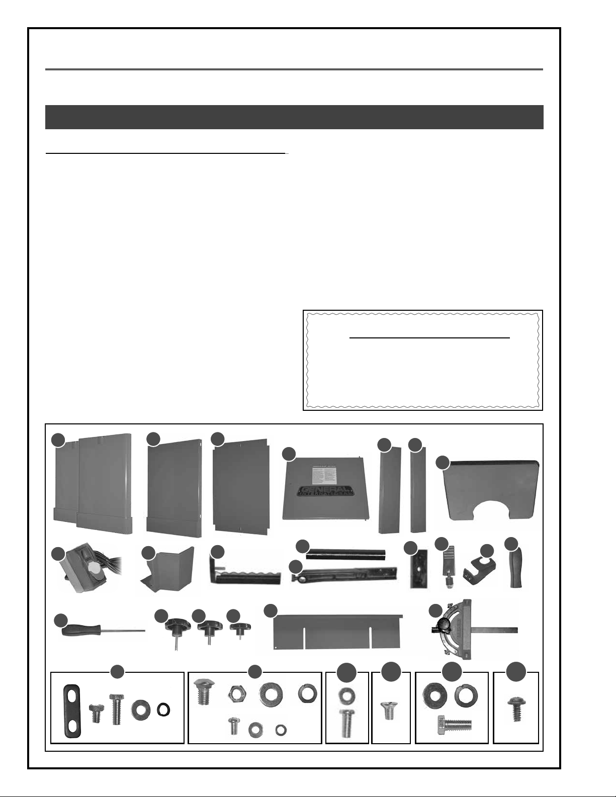
UNPACKING
Carefully unpack and remove the unit and its components from the box and check for missing or damaged items
as per the list of contents below.
NOTE: PLEASE REPORT ANY DAMAGED OR MISSING ITEMS TO YOUR GENERAL® INTERNATIONAL DISTRIBUTOR IMMEDIATELY.
LIST OF CONTENTS QTY
A. SIDE STAND PANEL ................................................................... 2
B. REAR STAND PANEL ................................................................. 1
C. BOTTOM STAND PANEL ............................................................ 1
D. STAND DOOR ........................................................................... 1
E. LOWER CROSSBAR (LARGER) ................................................. 1
F. UPPER CROSSBAR .................................................................... 1
G. AUXILIARY TABLE ...................................................................... 1
H. SWITCH ASSEMBLY ................................................................... 1
I. RIGHT DRUM GUARD ............................................................... 1
J. WORKPIECE STOP .................................................................... 1
K. AUXILIARY TABLE SUPPORT BRACKET ...................................... 1
L. AUXILIARY TABLE SUPPORT ARM ............................................. 1
M. RUBBER FEET ............................................................................. 4
N. DOOR LATCH ASSEMBLY ......................................................... 1
O. LATCH STOPPER ....................................................................... 1
P. LEVER TENSION LEVER HANDLE .............................................. 1
Q. DRUM TRACKING ADJUSTMENT TOOL ................................... 1
R. LOCK KNOB (RIGHT DRUM GUARD) ............................................... 1
S. LOCK KNOB (LEFT DRUM GUARD) .................................................. 1
T. LOCK KNOB (TABLE FENCE) .........................................................2
A
B C
U. TABLE FENCE* .......................................................................... 1
V. MITER GAUGE .......................................................................... 1
W. SANDING BELT* (NOT SHOWN) .............................................. 1
X. SANDING HEAD (NOT SHOWN) .............................................. 1
Y. HARDWARE TO MOUNT THE AUXILIARY TABLE .......................................... 1
Z. HARDWARE TO ASSEMBLE THE STAND .................................................... 1
AA. HARDWARE TO SECURE THE RUBBER FEET ............................................... 1
AB. SUNK SCREW TO MOUNT THE LACTH STOPPER ......................................... 2
AC. HARDWARE TO SECURE THE HEAD TO THE STAND ...................................... 1
AD. PHILLIPS SCREW TO SECURE THE SWTICH AND THE RIGHT GUARD (I) ............... 5
*The sanding belt and table fence are stored inside the sanding head
to prevent damage in shipping
ADDITIONAL REQUIREMENTS FOR SET UP
A. PHILLIPS SCREWDRIVER
B. FLAT HEAD SCREWDRIVER
C. 8, 10 & 12 MM WRENCHES
E F
D
G
A
H
Q
Y Z
8
I
R S T
J
U V
K
L
AA
M
AB
N
AC AD
P
O
Page 9
BASIC FUNCTIONS
This machine has been designed for sanding or polishing (removing kerf or pencil marks) on small workpieces,
such as chair legs or stand doors.
The sanding belt can be tilted at any angle between 90º and 180º for bevelled pieces. Flat sanding, with the belt
in the horizontal position (180º) is easier and safer for longer workpieces.
The auxiliary/end table can be installed on the end of the left side main table and used for sanding round or
curved surfaces.
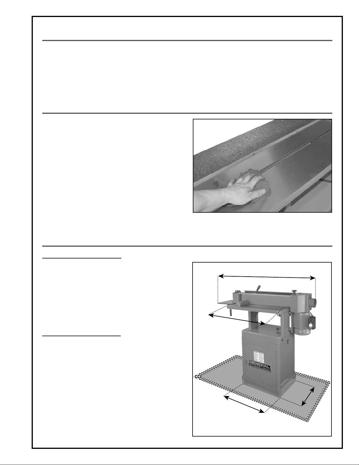
CLEANING
The protective coating on the table prevents rust from
forming during shipping and storage. Remove it by rubbing with a rag dipped in kerosene, mineral spirits or
paint thinner. (Dispose of potentially flammable solventsoaked rags according to manufacturer’s safety recommendations).
A putty knife, held flat to avoid scratching the surface,
may also be used to scrape off the coating followed
by clean-up with solvent. Avoid rubbing the machine’s
painted surfaces, as many solvent-based products will
remove paint.
To prevent rust, apply a light coating of paste wax or use
regular applications of any after-market surface protectant or rust inhibitor.
PLACEMENT WITHIN THE SHOP / SAFETY ZONE
PLACEMENT WITHIN THE SHOP
This machine should be installed and operated only on
a solid, flat and stable floor that is able to support the
weight of the machine (266 lbs - 121 kg) and the operator.
Using the dimensions shown as a guideline, plan for placement within your shop that will allow the operator to
work unencumbered and unobstructed by foot traffic
(either passing shop visitors or other shop workers) or
other tools or machinery.
ESTABLISHING A SAFETY ZONE
For shops with frequent visitors or multiple operators, it is
advisable to establish a safety zone around shop machinery.
A clearly defined “no-go” zone on the floor around each
machine can help avoid accidents that could cause injury to either the operator or the shop visitor.
It is advisable to take a few moments to either paint (using non-slip paint) or using tape, define on the floor the
limits or perimeter of each machines safety zone.
Take steps to ensure that all operators and shop visitors
are aware that these areas are off limits whenever a machine is running for everyone but the individual operating the unit.
3
0
"
2
1
"
5
0
"
"
6
1
9
Page 10

BEFORE ASSEMBLING, MAKE SURE THAT THE SWITCH IS IN THE “OFF” POSITION AND THAT THE POWER CORD IS
UNPLUGGED. DO NOT PLUG IN OR TURN ON THE MACHINE UNTIL YOU HAVE COMPLETED THE ASSEMBLY AND
INSTALLATION STEPS DESCRIBED IN THIS SECTION OF THE MANUAL.
ASSEMBLING THE STAND
1. Align the two rear panel mounting holes with the
corresponding holes on the right side panel.
3. Align the rear panel mounting holes with the cor-
responding holes on the left side panel.
2. Secure the panels by hand tightening a carriage
bolt with a washer, a lock washer and a nut.
4. Repeat step 2.
A
5. Install 2 carriage bolts into the lower part of the left
side panel.
7. Repeat step 2 on the two ends of the crossbar.
10
6. Slide the larger crossbar with the holes A on top
onto the two carriage bolts.
8. Install the bottom panel and align its mounting
holes with the corresponding holes on the stand.
Page 11

BEFORE ASSEMBLING, MAKE SURE THAT THE SWITCH IS IN THE “OFF” POSITION AND THAT THE POWER CORD IS
UNPLUGGED. DO NOT PLUG IN OR TURN ON THE MACHINE UNTIL YOU HAVE COMPLETED THE ASSEMBLY AND
INSTALLATION STEPS DESCRIBED IN THIS SECTION OF THE MANUAL.
ASSEMBLING THE STAND (CONTINUED)
B
9. Using a Phillips screwdriver, secure the bottom panel
with a screw, a washer and a lock washer B. Repeat
with the other side.
C
11. Slide the upper crossbar with the holes C facing
down onto the two carriage bolts.
10. Install 2 carriage bolts into the upper part of the left side
panel.
12. Repeat step 2 with the two ends of the crossbar.
13. Tighten all the nuts using a 12 mm wrench, then
turn the stand upside down.
15. Using a 12 mm wrench, secure the rubber feet with
a nut.
14. Install a rubber foot in each corner, then fit a flat
washer and screw inside each.
D
16. Using a Phillips screwdriver and two screws D, se -
cure the latch stopper to the left side panel.
11
Page 12

BEFORE ASSEMBLING, MAKE SURE THAT THE SWITCH IS IN THE “OFF” POSITION AND THAT THE POWER CORD IS
UNPLUGGED. DO NOT PLUG IN OR TURN ON THE MACHINE UNTIL YOU HAVE COMPLETED THE ASSEMBLY AND
INSTALLATION STEPS DESCRIBED IN THIS SECTION OF THE MANUAL.
ASSEMBLING THE STAND (CONTINUED)
17. Insert the lower door hinge pin into the hole in the
lower crossbar.
18. Then pull down on the spring lever and fit it into the
hole in the upper crossbar.
FE
19. Start by inserting the handle with a flat washer into
the door E.
INSTALLING THE MACHINE ON THE STAND
TIP: TO ASSEMBLE THIS UNIT, YOU WILL NEED TO LIFT THE HEAD OF THE MACHINE. DUE TO THE WEIGHT OF THE MACHINE, ADEQUATE
LIFTING EQUIPMENT SUCH AS A JACK, HOIST, OR FORKLIFT WITH STRAPS IS REQUIRED. ANY EQUIPMENT USED TO LIFT THE MACHINE MUST HAVE A MINIMUM WEIGHT CAPACITY OF 266 LBS (121 KG).
20. Then slide the rubber spacer, the smaller washer (see
the order illustrated in figure F) onto the threaded
rod and then tighten the nut with a 10 mm wrench.
1. With help of an assistant, install appropriate lifting
straps around the head, lift the machine head using
appropriate lifting equipment, then hold the head
above the stand and align the mounting holes.
Note: Verify the load capacity of the straps.
12
2. Using a 12 mm wrench, attach each end with a
bolt, lock washer and a medium flat washer.
Page 13

BEFORE ASSEMBLING, MAKE SURE THAT THE SWITCH IS IN THE “OFF” POSITION AND THAT THE POWER CORD IS
UNPLUGGED. DO NOT PLUG IN OR TURN ON THE MACHINE UNTIL YOU HAVE COMPLETED THE ASSEMBLY AND
INSTALLATION STEPS DESCRIBED IN THIS SECTION OF THE MANUAL.
INSTALLING A SANDING BELT
Note: Steps 7, 8 & 9 should be done only for the first installation of the machine.
REAR VIEW
1. Push the sanding head tilting adjustment lever forward
(under the sanding head) to unlock the sander.
2. Swivel the head into the vertical position.
REAR VIEW
3. While holding the machine head in position, pull
back the sanding head tilting adjustment lever.
4. Unscrew the lock knob that holds the right drum guard.
Then remove the guard and set it aside for now.
REAR VIEW REAR VIEW
REAR VIEWREAR VIEW
5. Remove the lock knob that holds the belt guard/
dust chute.
REAR VIEW
7. Remove the fence stored inside the sanding head and
set the fence aside for now.
6. Then remove the guard and set it aside for now.
REAR VIEW
8. Then remove the sanding belt.
13
Page 14

BEFORE ASSEMBLING, MAKE SURE THAT THE SWITCH IS IN THE “OFF” POSITION AND THAT THE POWER CORD IS
UNPLUGGED. DO NOT PLUG IN OR TURN ON THE MACHINE UNTIL YOU HAVE COMPLETED THE ASSEMBLY AND
INSTALLATION STEPS DESCRIBED IN THIS SECTION OF THE MANUAL.
INSTALLING A SANDING BELT (CONTINUED)
9. Install the sanding belt tension lever handle using a
mallet.
A
B
10. Set the sanding belt in the proper direction, making
sure the arrow A on the machine and the arrows B
inside the sanding belt point in the same direction.
11. Slide the sanding belt onto the drums.
LOOSE TIGHT
12. Intall the sanding belt so that it centered on the drums.
13. Position the belt tension lever to the “tight” position. 14. Turn the sanding belt by hand to confirm that it is
tracking properly. If not, perform steps 5 to 8 in the
Belt Tracking Adjustment section before going on
to the next steps.
REAR VIEW
REAR VIEW
15. Re-install the the guard/dust chute as shown. 16. Secure the guard by retightening the lock knob.
14
Page 15

BEFORE ASSEMBLING, MAKE SURE THAT THE SWITCH IS IN THE “OFF” POSITION AND THAT THE POWER CORD IS
UNPLUGGED. DO NOT PLUG IN OR TURN ON THE MACHINE UNTIL YOU HAVE COMPLETED THE ASSEMBLY AND
INSTALLATION STEPS DESCRIBED IN THIS SECTION OF THE MANUAL.
INSTALLING THE WORKPIECE STOP
TOP VIEW
17. Insert the workpiece stop rod into the hole in top of
the head.
19. Install the left guard and align its mounting holes
with the corresponding holes in the machine.
18. Align the workpiece stop mounting hole with the
corresponding hole in the machine
A
20. Using a Phillips screwdriver secure the guard with 3
screws A, then install the lock knob with a flat washer.
REAR VIEWREAR VIEW
21. Re-install the right drum guard, secure it in position
by tightening a lock knob with a flat washer.
INSTALLING THE AUXILIARY TABLE
A
REAR VIEW
1. Using a 10 mm wrench, secure the table bracket on
the right side with a bolt, lock washer & a flat washer A.
22. Secure with a second lock knob and a flat washer.
REAR VIEW
2. Place the table mounting arm under the left drum.
15
Page 16

BEFORE ASSEMBLING, MAKE SURE THAT THE SWITCH IS IN THE “OFF” POSITION AND THAT THE POWER CORD IS
UNPLUGGED. DO NOT PLUG IN OR TURN ON THE MACHINE UNTIL YOU HAVE COMPLETED THE ASSEMBLY AND
INSTALLATION STEPS DESCRIBED IN THIS SECTION OF THE MANUAL.
INSTALLING THE AUXILIARY TABLE
B
REAR VIEW
3. Using a 10 mm wrench secure the table arm to the
bracket with a bolt, a lock washer & a flat washer B.
5. Fit the table support post into the table mounting
hole, making sure the bolt is aligned with the flat
slide of the support post.
C
4. Using a 10 mm wrench, secure the arm to the frame
with a bolt, a lock washer and a flat washer C.
D
E
6. Using a 10 mm wrench secure the support post with
bolt D, then tighten the jam nut E.
7. Fit the table support post into the arm.
CONNECTING THE SWITCH
F
1. Using a Phillips screwdriver secure the switch to the
motor with 2 screws F.
16
8. Secure the table in place by tightening the lock
knob under the table.
2. Connect the power cord from the motor to the inlet
plug on the switch.
Page 17

BEFORE ASSEMBLING, MAKE SURE THAT THE SWITCH IS IN THE “OFF” POSITION AND THAT THE POWER CORD IS
UNPLUGGED. DO NOT PLUG IN OR TURN ON THE MACHINE UNTIL YOU HAVE COMPLETED THE ASSEMBLY AND
INSTALLATION STEPS DESCRIBED IN THIS SECTION OF THE MANUAL.
CONNECTING TO A DUST COLLECTOR
A dust outlet that fits 4” hose is provided to accommodate connection to a dust collector (not included). Be
sure to use appropriate sized hose and fittings (not included).
Check that all connections are sealed tightly to help
minimize airborne dust. If you do not already own
a dust collection system consider contacting your
General® International distributor for information on
our complete line of dust collection systems and accessories or visit our Web Site at www.general.ca.
ALWAYS TURN ON THE DUST COLLECTOR BEFORE
STARTING THE SANDER AND ALWAYS STOP THE SANDER BEFORE TURNING OFF THE DUST COLLECTOR.
BASIC ADJUSTMENTS & CONTROLS
TO REDUCE THE RISK OF SHOCK OR FIRE DO NOT OPERATE THE UNIT WITH A DAMAGED POWER CORD OR PLUG.
REPLACE A DAMAGED CORD OR PLUG IMMEDIATELY. TO AVOID UNEXPECTED OR UNINTENTIONAL START-UP, MAKE
SURE THE POWER SWITCH IS IN THE OFF POSITION BEFORE CONNECTING TO A POWER SOURCE.
CONNECTING TO A POWER SOURCE
Once the assembly steps have been completed, plug
the power cord into an appropriate outlet.
SWITCH OFF
Refer back to the section entitled “Electrical Requirements” and make sure all requirements and grounding instructions are followed.
When operations have been completed unplug the
machine
from the power source.
TO AVOID UNEXPECTED OR UNINTENTIONAL
START-UP, MAKE SURE THAT THE POWER SWITCH
IS IN THE OFF POSITION BEFORE CONNECTING
TO A POWER SOURCE.
ON/OFF POWER SWITCH
The machine is equipped with a rocker type ON/OFF switch that is equipped with a lock-out key.
To start the machine, insert the lock-out key and pull up the switch A.
To stop the machine, push down on the power switch B.
To prevent unwanted or unauthorized start-up, remove the lock-out key C and store it in a safe place.
Note: When the machine comes to a complete stop, remove the lock-out key C by gently pulling it outward.
A B
C
POWER ON
POWER OFF
SAFETY KEY
(PREVENTS START-UP
WHEN REMOVED)
17
Page 18

MAKE SURE THE MACHINE HAS BEEN TURNED OFF AND UNPLUGGED FROM THE POWER SOURCE BEFORE PERFORMING ANY MAINTENANCE OR ADJUSTMENTS.
ADJUSTING THE HEIGHT OF THE MAIN TABLE
Adjusting the height of the table allows an even wearing of the sanding belt surface. To maximize belt usage when
working with shorter workpieces, periodically adjust the table height to systematically make use of various portions
of the belt. For example; a series of 2” tall workpieces can be separated into 3 smaller batches with each batch being sanded with the table set at different heights to use in sequence the lower, middle or upper portion of the belt.
To adjust the height of the table, proceed as follows:
REAR VIEW
1. Push the tilting adjustment lever forward to unlock
the sanding head.
REAR VIEW
3. While holding the machine head in position, pull
back the sanding head tilting adjustment lever.
2. Swivel the head into the vertical position.
A
4. Loosen the two lock knobs A located under the work
table.
5. Set a level on the table while adjusting the table to
the desired height. Once the table height is adjusted, retighten the two lock knobs.
18
6. Sand a batch of workpieces at the same height,
then lower the table to use a different portion of the
sanding belt.
Note: It is recommended to start by the upper portion of the
sanding belt making it easier to lower the table as needed.
Page 19

MAKE SURE THE MACHINE HAS BEEN TURNED OFF AND UNPLUGGED FROM THE POWER SOURCE BEFORE PERFORMING ANY MAINTENANCE OR ADJUSTMENTS.
ADJUSTING THE ANGLE OF THE SANDING HEAD
Depending upon your needs, the sanding head can be adjusted to any angle from 90º to 180º.
REAR VIEW
A
1. Push the head tilting adjustment lever forward to
unlock the sanding head.
INSTALLING AND ADJUSTING THE MITER GAUGE (IF NEEDED)
The miter gauge allows for easier and safer sanding by providing workpiece support when sanding straight (90°)
or angled ends (30° to 90°). The miter gauge supplied with your sander is adjustable from 30° to 90° right to left,
and has adjustable index stops at 90° and 45° to the right and left.
1. Loosen the miter gauge handle, then Insert the mi-
ter gauge into the “T” slot in the table.
To square the miter gauge:
2. Tilt the head to the required angle on the angle indicator scale A. Make sure to pull the lever back to lock
the head in position before starting the machine.
2. Lift tab as shown to adjust the angle with the graduated scale. Once the miter gauge is adjusted, retighten the handle to hold it in position.
1. Place a square as shown to adjust the miter
gauge to 90°. Tighten the miter gauge handle.
B
A
2. Loosen the nut A with a 8 mm wrench, then turn
the set screw B with a 2 mm Allen key so that it is
againt the tab C. Retighten the nut A.
C
19
Page 20

MAKE SURE THE MACHINE HAS BEEN TURNED OFF AND UNPLUGGED FROM THE POWER SOURCE BEFORE PERFORMING ANY MAINTENANCE OR ADJUSTMENTS.
SELECTING A SANDING BELT
Note: To install a sanding belt, see section“Installing a sanding belt”.
Standard size (6” x 89”) replacement belts can be purchased in a variety of grits from your General® International
dealer under the following parts numbers: 15-006 - 80, 15-007 - 100, 15-008 - 120, 15-009 - 150; or (depending on
availability) from your local tool, abrasives or sharpening supply dealer.
These are standard sizes that should be readily available in most areas. The use of any other size is not recommended and can lead to serious injury and/or damage to the machine.
Note: For best unobstructed access remove the belt guards, workpiece stop and dust hood, whenever changing sanding belts.
Tip: To extend belt life and avoid premature breakage, take note of the direction arrows printed on the inside of the
sanding belt to make sure you install the belt in the correct direction.
BELT TRACKING ADJUSTMENT
Note: Belt tracking adjustments may be necessary after changing or replacing a sanding belt, to counterbalance for
uneveness between sanding belts.
Though not essential, proper belt tracking (having the belt running straight as evenly on the drums as possible)
can prolong belt life and avoid having the belt slip off during operation.
This is done by tilting the left drum (opposite side to the motor) slightly towards the front or rear, so that the belt
does not get uncentered and stays on the middle of the drums.
Turn on the machine on for 5-10 seconds to visually confirm the belt tracking. If the belt is tracking straight, you
are ready to sand. Re-install the belt guards, workpiece stop and proceed with normal operations.
If the belt is not tracking straight, follow the instructions below before proceeding with normal sanding operations.
1. Remove the two guard lock knobs.
3. Remove the right drum guard lock knob and the 3
screws using a Phillips screwdriver.
20
2. Remove the left drum guard.
4. Remove the right drum guard.
Page 21

MAKE SURE THE MACHINE HAS BEEN TURNED OFF AND UNPLUGGED FROM THE POWER SOURCE BEFORE PERFORMING ANY MAINTENANCE OR ADJUSTMENTS.
BELT TRACKING ADJUSTMENT (CONTINUED)
A
5. Using the tracking adjustment tool, loosen the jam nut A.
C
B
6. Turn the set screw B in the direction required to tilt the
drum forward or backward.
7. Turn the machine on for 5-10 seconds to visually confirm the belt tracking C. As needed, turn off the machine and repeat this adjustment process until the
belt is tracking evenly on the drums.
8. Once the sanding belt tracking adjustment is complete,
retighten the jam nut. Re-install the workpiece stop
and all the guards before starting the machine.
OPERATING INSTRUCTIONS
CHECKLIST BEFORE STARTING
VERIFY ALL CHECK POINTS BEFORE STARTING. FAILURE TO COMPLY CAN RESULT IN SERIOUS INJURIES.
1. Make sure you and any assistants are wearing safe appropriate workshop attire. Roll up long sleeves, secure
long hair and remove any jewelry: watches, rings, bracelets or anything that could become caught in the
moving parts, potentially causing serious injury.
2. To reduce the risk of damage to the machine, as well as potential for personal injury, after initial set-up as well
as before each use, make sure that everything is securely installed and that all fasteners and moving parts on
this machine are locked in place before starting the machine.
3. Make sure to have on safety glasses as well as hearing or/and respiratory protection at all times when using the
machine.
4. Use only recommended parts and accessories. The use of parts or accessories NOT recommended by
GENERAL® INTERNATIONAL may result in a risk of injury or damage to the machine.
5. Be sure that adjusting wrenches, tools, drinks and other clutter are removed from the machine and/or the
table surface before operating.
21
Page 22

INSTALLING AND ADJUSTING THE TABLE FENCE (IF NEEDED)
The fence allows easier and safer sanding, providing support for long workpieces.
A
1. Align both blocks A inside the slot in the table, with
both holes in the fence, then secure them with medium flat washers and short lock knobs.
USING THE WORKPIECE STOP USING THE AUXILIARY TABLE
The workpiece stop acts as a stopper to prevent the
workpiece from being carried away or flung from the
machine by the rotation of the sanding belt. The workpiece stop also acts as a fence to assist in maintaining
control over the workpiece making it easier and safer
to hold the workpiece flat to the belt for an even, more
uniform sanding job.
Note: The fence can also be positioned diagonal to the
belt, allowing you to sand bevelled workpieces.
Install the auxiliary/end table on the left side of machine when you need support for sanding rounded or
curved workpieces. See section “Installing the Auxiliary
table”, if needed.
MAINTENANCE
MAKE SURE THE MACHINE HAS BEEN TURNED OFF AND UNPLUGGED FROM THE POWER SOURCE BEFORE PERFORMING ANY MAINTENANCE OR ADJUSTMENTS.
PERIODIC MAINTENANCE
• Inspect/test the ON/OFF switch before each use. Do not operate the sander with a damaged switch; replace
a damaged switch immediately.
• Keep the machine as well the table clean and free of saw dust, woodchips, pitch or glue.Vacuum or brush off
any loose debris and wipe down the machine and the table occasionally with a damp rag.
• An occasional light coating of paste wax can help protect the table surface and reduce workpiece friction.
Ask your local distributor for suggestions on aftermarket surface cleaners, protectant and dry lubricants based
on what is readily available in your area.
• Avoid using silicon based products that may affect or react with wood finishing products such as oil, solvent or
water-based stains, varnishes and lacquers.
• Periodically inspect the power cord and plug for damage. To minimize the risk of electric shock or fire, never
operate the sander with a damaged power cord or plug. Replace a damaged power cord or plug at the first
visible signs of damage.
• Drums must always be kept clean. Dirt on drums will cause poor tracking and belt slippage.
22
Page 23

MAKE SURE THE MACHINE HAS BEEN TURNED OFF AND UNPLUGGED FROM THE POWER SOURCE BEFORE PERFORMING ANY MAINTENANCE OR ADJUSTMENTS.
SQUARING THE SANDING BELT WITH THE WORK TABLE
The sanding belt has been squared to the table at the factory, therefore except in some rare cases (important maintenance, improper or transport rough handling) no further adjustments are required. Proceed as follows if needed:
B
A
1. Place the belt in the vertical position the set a square
on the table as shown. If the sanding belt is not
square with the table, go to the next step.
2. Using a 12 mm wrench loosen the two jam nuts A
located in the back of the machine. Turn the bolts B
until the sanding belt is square with the work table.
then retighten the jam nuts.
LUBRICATION
Note: All motor and drum bearings are sealed and permanently lubricated. No further lubrication is needed.
1. Clean and grease the belt tension mechanism reg-
ularly with an all purpose grease.
2. Make sure that the belt tilting mechanism is clean
and lubricated. Lubricate as needed with an all pupose grease.
REPLACING THE GRAPHITE COATING
The graphite coating on the platen C will wear and over
time require replacement. Every 3 years (approx) in
small shop settings and up to 10 years in home shop settings, the graphite coating will begin to show visible signs
of wear and will need to be peeled off (using a solvent
based stripper) and removed.
A replacement graphite coated paper strip should be
glued (with contact cement) onto the platen in it’s place.
Most retail outlets that sell stationary power tools and
abrasives products do stock graphite replacement strips
for most popular sizes of sanders.
C
23
Page 24

RECOMMENDED OPTIONAL ACCESSORIES
Here is a sampling of optional accessories available from your local General International dealer that can be
used with this product. For more information about our products, please visit our website at www.general.ca
DUST COLLECTORS
Dust collectors contribute to a cleaner more
healthful workshop environment.
We offer a wide selection of top quality dust
collectors to suit all your
shop needs.
item #50-025
MOBILE BASE
Easily roll your sander
anywhere in your shop.
Load capacity: 500 lbs.
Wheels lock when equipment is in use.
Item #10-130/10-410
HEAVY-DUTY POLYETHYLENE FLEXIBLE HOSES
10-130: 4” X 50’
10-410: 4” X 10’
SANDING BELTS
STANDARD SIZE (6” BY
89”)
15-006 - 80 Grit
15-007 - 100 Grit
15-008 - 120 Grit
15-009 - 150 Grit
NOTES
24
Page 25

71
63
DIAGRAM
15-005
36
63
104
103
104
71
63
43B
43
42
44
45
44
46
71
48
49
50
63
69A
91
92
93
69
47A
63
40
94
62
41
79
47
98
95
96
78
81
38
55
77
63
35
90
34B
56
50
138
57
58
141
100
92
51
82
83
91
80
97
91
99
73
77
78
26
27
87
102
28
65
109
64
34
63
54
28A
60
33
30
24
50
25
59
32
31
18
29
37A
61
62
19A
65
19
22
63
15
16
23
14
136
19A
19
22
63
64
17A
71
135
63
63
118
22
63
21
70
63
39
132
126
104
127
133
2
134
83
137
62
20
17
9
63
1
77
78
87
88
77
89
73
74
117
119
123
139
124
140
141
116
125
121
122
120
114
75
101
115
112
13
12
8
10
10A
25
Page 26

PARTS LIST
IMPORTANT: When ordering replacement parts, always give the model number, serial number of the
machine and part number. Also a brief description of each item and quantity desired.
PART # REFERENCE # DESCRIPTION QTY
15005-01 20101001 BASE 1
15005-02 W2010002A SWITCH 1
15005-08 20101005 LONG SCREW 1
15005-09 20101006 NUT 1
15005-10 20101007 ECCENTRIC CAM 1
15005-10A S0110600 NUT 1
15005-11 S0310525 PIN 1
15005-12 10102024 LOCKHANDLE 1
15005-13 10102023 KNOB 1
15005-14 S0410525 KEY 1
15005-15 S0020416 HEX HD. BOLT 1
15005-16 S0210404 WASHER 1
15005-17 20101011A TABLE 1
15005-17A S0020510 HEX HD. SCREW 4
15005-18 20101065 SCREW 2
15005-19 S0111015M HEX NUT 2
15005-19A S0230308 LOCK WASHER 2
15005-20 20101013 GUIDE BLOCK 2
15005-21 20101014 FENCE 1
15005-22 20101015 KNOB 3
15005-23 20101016 MOTOR ROLLER 1
15005-24 GUIDE BAR 1
15005-25 PIN 1
15005-26 SET SCREW 1
15005-27 LOCATING PLATE 1
15005-28 POINTER 1
15005-28A LOCATING BLOCK 1
15005-29 20101021 SANDING BELT 1
15005-30 MITER GAGE BODY 1
15005-31 SCREW 3
15005-32 HEX NUT 3
15005-33 LOCK HANDLE 1
15005-34 20101048 TABLE 1
15005-34B 20101049 PLATEN 1
15005-35 20103023 TENSION BAR 1
15005-36 20101039 KNOB 1
15005-37A S0310640 PIN 1
15005-38 20103025 SPRING 1
15005-39 20101055 PARTITION RING 1
15005-40 S0020501A HEX HD. BOLT 1
15005-41 20103050 ROLLER ARM 1
15005-42 20103051 SHAFT 1
15005-43 S0120200 LOCK NUT 1
15005-43B 20103029B STEEL BALL 1
15005-44 S0716004 BEARING 2
15005-45 20103028 IDLER ROLLER 1
15005-46 S0520017 SPRING RING 1
15005-47 20103029 MICRO ADJUST SCREW 1
15005-47A 20103029A MICRO ADJUST NUT 1
15005-48 20201013 COVER 1
15005-49 S0030304 SCREW 4
15005-50 S0230300 LOCK WASHER 6
15005-51 20101031 BELT TENSION PLATE 1
15005-54 20101032A TENSION HANDLE 1
15005-55 S0020530 HEX HD. BOLT 1
15005-56 S0120201 LOCK NUT 1
15005-57 20101033 TILT SCALE 1
15005-58 S0030318 SCREW 1
15005-59 10102022 ANGLE POINTER 1
15005-60 S0030304 SCREW 2
15005-61 M0000000 MOTOR 1
15005-62 S0020520 HEX HD. BOLT 4
15005-63 S0210500C WASHER 21
15005-64 S0230506 LOCK WASHER 8
15005-65 S0110500 HEX NUT 6
15005-67 L000000M SWITCH CORD 1
15005-69 20101034G BELT COVER 1
15005-69A 20101038A GUARD 1
15005-70 20101002 LIFTING PLATE 2
15005-71 20101024 KNOB 3
15005-72 20101040 BRACKET 1
15005-73 20104053G SIDE PANELS 2
15005-74 20104054G REAR PANEL 1
15005-75 20104060G DOOR FRAME 1
15005-77 S0210500 WASHER 28
15005-78 S0230506 LOCK WASHER 28
15005-79 S0110500 NUT 16
15005-80 S0020510 CARRIAGE BOLT 12
15005-81 20103044 TRACKING ADJUST. TOOL 1
15005-82 S0040512M SCREW 8
15005-83 S0220300 SPROCKET WASHER 8
15005-87 S0020520 HEX HD BOLT 2
15005-88 10401029 PAD 4
15005-89 S0090512 SCREW 4
15005-90 S0110500 NUT 4
15005-91 S0210403 WASHER 3
15005-92 S0230400 LOCK WASHER 2
15005-93 S0020615M SCREW 1
15005-94 20101051 SIDE TABLE 1
15005-95 60105012 KNOB 1
15005-96 20101050 SUPPORTING ROD 1
15005-97 40101016B MOUNTING BRACKET 1
15005-98 20101052 BRACKET 1
15005-99 S0020412 HEX HD. BOLT 3
15005-100 J000002 ANGLE SCALE 1
15005-101 I200011 WARNING LABEL 1
15005-102 I200010 DIRECTION LABEL 1
15005-103 20104044G DUST GUARD 1
15005-104 S0030300A PHILLIPS HEAD SCREW 2
15005-109 I2000009 TENSION LABEL 1
15005-112 J000000 NAME PLATE 1
15005-114 20104058G UPPER CROSS BAR 1
15005-115 20104059G LOWER CROSS BAR 1
15005-116 21004052G BOTTOM STAND PANEL 1
15005-117 20104061G DOOR LATCH STOPPER 1
15005-118 20101048A GRAPHITE SHEET 1
15005-119 S0040404 SCREW 2
15005-120 12100038 DOOR LATCH HANDLE 1
15005-121 12100039 DOOR LATCH PIN 1
15005-122 S0310312 SPRING PIN 1
15005-123 S0120400M NUT 1
15005-124 S0210300B WASHER 1
15005-125 12100040 DOOR LATCH RUBBER 1
15005-126 S1007P-2 STRAIN RELIEF 2
15005-127 20101044 SWITCH BRACKET 1
15005-132 L0000132 POWER CORD 1
15005-133 12100038 SWITCH BOX 1
15005-134 S0030306 PHILLIPS HEAD SCREW 2
15005-135 S00703006 PHILLIPS HEAD SCREW 3
15005-136 L0000111-1P SWITCH CORD 1
15005-137 L0000112-2 MOTOR CORD 1
15005-138 S0020401 HEX HEAD BOLT 2
15005-139 S0030510M PHILLIPS HEAD SCREW 2
15005-140 S0230500M LOCK WASHER 2
15005-141 S0210303 WASHER 2
26
Page 27

NOTES
27
Page 28

8360 Champ-d’Eau, Montreal (Quebec) Canada H1P 1Y3
Tel.: (514) 326-1161
Fax: (514) 326-5565 - Parts & Service / (514) 326-5555 - Order Desk
orderdesk@general.ca
www.general.ca
Follow us:
 Loading...