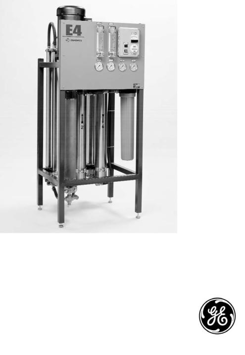
GE E4, EZ4, E4LE User Manual

OSMONICS
E4, E4LE, EZ4 SERIESTM
WATER PURIFICATION
MACHINES
INSTALLATION, OPERATION,
AND MAINTENANCE
MANUAL
GE Infrastructure
Water & Process Technologies

INSTALLATION, OPERATION AND
MAINTENANCE MANUAL
E4, E4LE, AND EZ4 SERIES
WATER PURIFICATION MACHINES
|
|
|
TABLE OF CONTENTS |
|
|
|
|
|
Page |
2.0 |
INSTALLATION |
1 |
||
|
2.1 |
Mounting the Unit |
1 |
|
|
2.2 |
Plumbing |
1 |
|
|
2.3 |
Installing Clean-In-Place Valves |
2 |
|
|
2.4 |
Concentrate Outlet Connections |
2 |
|
|
2.5 |
Feed Water Requirements |
2 |
|
|
2.6 |
Transporting Pure Water (Permeate) to Point-of-Use |
3 |
|
|
2.7 |
Pressure Correction Factors |
4 |
|
|
2.8 |
Electrical |
5 |
|
|
|
2.8.1 |
Single-Phase Electrical |
5 |
|
|
2.8.2 |
Three-Phase Electrical |
5 |
|
2.9 |
Machine Control |
6 |
|
|
|
2.9.1 |
Economy Model |
6 |
|
|
2.9.2 |
Deluxe Model |
6 |
|
2.10 |
Pretreatment for Water Purification |
7 |
|
|
2.11 |
Machine Start-Up Preparation |
7 |
|
|
2.12 |
Machine Start-Up |
7 |
|
|
2.13 |
Temperature Correction Factors |
9 |
|
|
2.14 |
Recovery |
10 |
|
|
2.15 |
Autoflush Timer |
11 |
|
|
|
2.15.1 Programming the Autoflush Timer |
11 |
|
|
|
2.15.2 Setting-Up the Autoflush Timer Clock |
11 |
|
|
|
2.15.3 Programming the Autoflush Timer Clock |
12 |
|
|
|
2.15.4 Programming Twenty-Four Hour or Seven Day Schedules |
13 |
|
|
|
2.15.5 Changing a Program |
13 |
|
|
|
2.15.6 Deleting a Program |
13 |
|
|
|
2.15.7 Troubleshooting the Autoflush Timer |
14 |
|
|
2.16 |
Calibrating the Conductivity Probe |
15 |
|

|
|
Page |
2.17 |
Operation and Maintenance |
16 |
|
2.17.1 Daily Flushing for the Economy Model |
16 |
|
2.17.2 Daily Flushing for the Deluxe Model |
16 |
2.18 |
Pre-Filter Cartridge |
17 |
2.19 |
Membrane Element Cleaning |
17 |
|
2.19.1 Step Wise Cleaning |
17 |
|
2.19.2 Procedure to Clean with a CIP Pump |
17 |
2.20 |
Suction Cleaning |
19 |
2.21 |
Changing Out Membrane Elements |
20 |
2.22 |
Troubleshooting |
22 |
|
LIST OF FIGURES |
|
Figure |
Description |
|
2.1 |
Three-Phase Allen Bradley Motor Starter |
6 |
2.2 |
Setting-Up the Correct Time on the Autoflush Timer |
11 |
2.3 |
Programming the Timer |
13 |
2.4 |
Conductivity Probe Display |
15 |
2.5 |
Clean-In-Place Pump and Tank Hook-Up |
18 |
|
LIST OF TABLES |
|
Table |
Description |
|
2.1 |
Connections |
1 |
2.2 |
E-Series Feed Water Requirements |
3 |
2.3 |
Pressure Correction Factors |
4 |
2.4 |
Flow Specifications for E4-Series Machines |
10 |

2.0INSTALLATION
2.1Mounting the Unit
When installing your new GE Infrastructure Water & Process Technologies reverse osmosis (RO) machine, allow at least 45-inches (114 cm) above the machine for membrane element removal and loading. If space is not available, the entire membrane element housing can be removed for membrane element change outs. If the membrane element housings are to be removed to change out the membrane elements, at least 6-inches (15.2 cm) is required at the end of each membrane element housing and 24-inches (61 cm) behind the machine.
2.2Plumbing
The feed water source must be able to provide water quantity and pressures to maintain an operating feed water pressure of 30 - 60 psig (2.1 - 4.1 barg). If the feed water pressure with the machine is in excess of 60 psig (4.1 barg) or fluctuates by more than 5 psig (0.34 barg) a pressure regulator should be installed up stream of the machine Inlet. If proper water pressure cannot be maintained to the RO, a booster pump may need to be installed in front of the pretreatment to provide the proper water quantity and pressure for the operation of the machine.
Table 2.1
Connections
E4/EZ4/E4LE* |
INLET |
|
PERMEATE |
CONCENTRATE |
MACHINE |
inches (cm) |
|
inches (cm) |
inches (cm) |
|
|
|
|
|
2200 |
0.75 (1.90) |
0.50 (1.27) |
0.50 (1.27) |
|
|
|
|
|
|
4400 |
0.75 (1.90) |
0.50 (1.27) |
0.50 (1.27) |
|
|
|
|
|
|
6600 |
0.75 (1.90) |
0.50 (1.27) |
0.50 (1.27) |
|
|
|
|
|
|
8800 |
0.75 (1.90) |
0.75 (1.90) |
0.75 (1.90) |
|
|
|
|
|
|
11000 |
0.75 (1.90) |
0.75 (1.90) |
0.75 (1.90) |
|
|
|
|
|
|
13200 |
0.75 (1.90) |
0.75 (1.90) |
0.75 (1.90) |
|
|
|
|
|
|
*Low Energy Membrane Elements
1
2.3Installing Clean-In-Place Valves
NOTE: Clean-In-Place (CIP) valves are not included with the machine. The CIP valves must be purchased and installed by the customer.
When installing the CIP valves, a three-way valve should be installed in the inlet feed stream of the machine. The tees on the permeate and concentrate lines should be installed with two-way valves. All valves should be installed in a manner that will allow circulation of the cleaning chemicals through the machine and back to the CIP container during cleaning.
CAUTION: If CIP valves are not installed when machine is installed, provisions must be made to bypass permeate and concentrate to drain for flushing at start-up.
WARNING: NEVER OPERATE THE MACHINE WITH THE CONCENTRATE OR PERMEATE LINES BLOCKED. SEVERE DAMAGE TO THE UNIT MAY RESULT.
2.4Concentrate Outlet Connections
Connect proper size drain line to the concentrate outlet (Table 2.1) and run to an open drain. The drain capacity needs to be large enough to properly drain the feed water flow of the RO. The maximum concentrate back pressure is 60 psig (4.1 barg) for the RO machine.
CAUTION: Operation above 60 psig (4.1 barg) concentrate back pressure may damage the machine.
2.5Feed Water Requirements
The following feed water requirements must be met before installing your new E4 machine to ensure quality permeate and extended membrane element life. Refer to Table 2.2 (E-Series Feed Water Requirements) for feed water information.
2

Table 2.2
E-Series
Feed Water Requirements
Temperature |
Typical: |
50° - 85°F (10° - 29°C) |
|
Limits: |
33° - 104°F (0.16° - 40°C) |
|
|
|
Inlet Pressure |
Minimum: |
30 psig (2.1 barg) |
|
Maximum: |
60 psig (4.1 barg) |
|
|
|
Chlorine |
0 parts per million (ppm) |
|
(continuous feed) |
|
|
|
|
|
Operating pH |
5.5 - 8.5 |
|
|
|
|
Silt Density |
Less than or equal to 5 to minimize |
|
Index (SDI) |
membrane element fouling and |
|
|
extend cleaning intervals. |
|
|
Refer to ASTM* standard D4189. |
|
|
|
|
*American Standard for Testing Materials
2.6Transporting Pure Water (Permeate) to Point-of-Use
The pure water, or permeate, is in an aggressive state and should only be transported from the machine to the point-of-use in food grade flexible nylon, stainless steel
(SS)tubing, or polyvinyl chloride (PVC) material for the inlet, permeate, and concentrate piping sizes. Refer to Connections (Table 2.1) for inlet, permeate, and concentrate piping sizes.
WARNING: MACHINE DAMAGE MAY OCCUR IF PERMEATE BACK PRESSURE EXCEEDS 60 PSIG (4.1 BARG) DURING OPERATION.
3

2.7Pressure Correction Factors
It is often necessary to operate RO machines with permeate back pressure. Permeate back pressure will decrease permeate production. See Table 2.3 (Pressure Correction Factors) to calculate loss of permeate.
Table 2.3
Pressure Correction
Factors
|
|
|
|
PRESSURE |
|
|
% LOSS OF |
|
CORRECTION |
||
BACK PRESSURE |
PERMEATE FLOW |
|
FACTOR (PCF) |
||
|
|
|
|
|
|
|
E4/EZ4 |
E4LE |
|
E4/EZ4 |
E4LE |
|
|
|
|
|
|
10 psig (0.7 barg) |
5% |
10% |
|
0.95 |
0.90 |
|
|
|
|
|
|
20 psig (1.4 barg) |
10% |
20% |
|
0.90 |
0.80 |
|
|
|
|
|
|
30 psig (2.0 barg) |
15% |
30% |
|
0.80 |
0.70 |
|
|
|
|
|
|
40 psig (2.7 barg) |
20% |
40% |
|
0.70 |
0.60 |
|
|
|
|
|
|
50 psig (3.4 barg) |
25% |
50% |
|
0.60 |
0.50 |
|
|
|
|
|
|
60 psig (4.1 barg) |
30% |
60% |
|
0.50 |
0.40 |
|
|
|
|
|
|
WARNING: IF PERMEATE BACK PRESSURE EXCEEDS 60 PSIG (4.1 BARG) MACHINE DAMAGE MAY OCCUR.
WARNING: INSTALLING A CHECK VALVE WILL PREVENT REVERSE FLOW THROUGH THE MEMBRANE ELEMENT WHEN THE MACHINE IS NOT IN OPERATION. REVERSE FLOW, WHEN THE MACHINE IS NOT IN OPERATION, CAN SEVERELY DAMAGE THE MEMBRANE ELEMENTS.
4
2.8Electrical
This RO machine requires two supply voltages; the control voltage and the pump motor voltage.
2.8.1Single-Phase Electrical
The control voltage can be connected to either a 115 VAC, 60 Hertz or 220 VAC, 50 Hertz single-phase power supply. The RO control circuit should always be installed on at least a 15 Amp, single-phase dedicated circuit. Reverse osmosis machines with 115 VAC, single-phase control voltage include an eight-foot (2.4 m) cord which plugs into a three-prong grounded receptacle. All machines shipped with a 220 VAC, single-phase control circuit are shipped with an eight-foot electrical cord, but customers must provide electrical plug.
2.8.2Three-Phase Electrical
The three-phase pump motor requires a 15 AMP dedicated circuit. Always verify correct voltage and Amp rating by checking voltage tag on the starter box or by checking electrical specifications on the pump. The motor is wired for 460 Volts, 60 Hertz, three-phase voltage from the factory (Figure 2.1, Three-Phase Allen Bradley Motor Starter). The pump motor can be rewired to 208 or 230 Volts. If this is done, a wiring change must be made internally in the pump motor and a higher amperage relay and starter may need to be installed. All field wiring must comply with applicable local and national electrical codes.
After checking the voltage tag on the motor starter to ensure the available voltage and amperage are correct, connect the provided three-phase power to the motor starter (Figure 2.1). This can be done by connecting the three phase power to the top of the starter relay terminals: L1, L2, and L3. A separate, fused disconnect for the motor wiring with proper protection for the Horsepower and Amp draw of the motor is recommended. All field wiring must comply with applicable local and national electrical codes. See Figure 2.1 for threephase Allen Bradley Starter Hook-Up.
5
 Loading...