


AF-300
MICRO-$AVER II TM
1/4 - 5 Horsepower
Instructions

General Information – AF-300 Micro-$aver II ™ Drive Instructions
These instructions do not purport to cover all details or variations in equipment, nor to provide for every possible contingency to be met during installation, operation, and maintenance. Should further information be desired or should particular problems arise that are not covered sufficiently for the purchaser's purpose, the matter should be referred to GE Fuji Electric, Customer Service.
This document contains proprietary information of GE Fuji Electric and is furnished to its customers solely to assist that customer in the installation, testing, and/or maintenance of the equipment described. This document shall not be reproduced in whole or in part nor shall its contents be disclosed to any third party without the written approval of GE Fuji Electric.
NOTE: The terms "inverter", "controller", and "drive" are sometimes used interchangeably throughout the industry. We will use the term "Drive" in this document.
AF-300 Micro-Saver II™ and X$D™ are trademarks of General Electric Company. Energy Saver® is a registered trademark of General Electric Company.
The terms "AF-300 Micro-Saver II" and AF-300M$II will be used interchangeably throughout this document.
WARNING: Always read the complete instructions prior to applying power or troubleshooting the equipment and follow all procedures step by step.
SHOCK HAZARD labels may be located on or inside the Drive to alert people that dangerous voltage may be present. (Refer to Section 1: Safety Precautions for Warnings and Cautions.)
Blank space has been intentionally left at the bottom of each page for the convenience of the user in documenting notes.
i
TABLE OF CONTENTS
Section |
Title |
Page |
1. |
SAFETY PRECAUTIONS |
.......................................................................... 1-1 |
2.DESCRIPTION, COMPONENT IDENTIFICATION,
AND SPECIFICATIONS ............................................................................ |
2-1 |
General Description .................................................................................. |
2-1 |
Delivery Inspection Procedures ............................................................... |
2-1 |
Nameplate Data......................................................................................... |
2-1 |
Drive Keypad Functions and Layout ........................................................ |
2-2 |
Drive Components .................................................................................... |
2-3 |
Table 1: Standard Specifications .............................................................. |
2-4 |
Table 2: Drive Dimensions ....................................................................... |
2-7 |
Table 3: Drive Ratings, Efficiencies and Watts Loss ................................ |
2-7 |
3. |
INSTALLATION GUIDELINES .................................................................. |
3-1 |
|
Installation Environment.......................................................................... |
3-1 |
|
Installation Mounting Clearance ............................................................. |
3-1 |
|
Dimension Drawings ................................................................................. |
3-2 |
|
Dimensions of Keypad Mounting Holes .................................................. |
3-4 |
4. |
WIRING PROCEDURES ........................................................................... |
4-1 |
|
Remove Terminal Top Cover ................................................................... |
4-1 |
|
Control Circuit Wiring.............................................................................. |
4-2 |
|
Main Circuit Wiring .................................................................................. |
4-3 |
|
Table 4: Drive Wire Size Recommendations ........................................... |
4-4 |
|
and Circuit Protection Rating |
|
|
Control/Circuit Terminal Block .............................................................. |
4-5 |
|
Drive Wiring Diagram ............................................................................... |
4-6 |
|
Table 5: Terminal Identification/Function ............................................ |
4-7 |
|
Drive Interface Details .............................................................................. |
4-9 |
5. |
DRIVE OPERATION .................................................................................. |
5-1 |
|
Keypad Panel Identification/Operation ................................................. |
5-1 |
|
Function Code and Data Code Description/Selection .......................... |
5-1 |
|
Keypad and Display Operation Programming ........................................ |
5-2 |
|
Stop Mode ................................................................................................. |
5-3 |
|
Run Mode .................................................................................................. |
5-4 |
|
Program Mode while stopped .................................................................. |
5-5 |
|
Program Mode while running .................................................................. |
5-6 |
|
Trip Mode.................................................................................................. |
5-7 |
|
Summary of Operating Modes ................................................................. |
5-8 |
|
Pre-Operation Inspection ......................................................................... |
5-9 |
|
Table 6: Function Code List ..................................................................... |
5-10 |
6. |
FUNCTION CODE DESCRIPTIONS (01 thru 79) ..................................... |
6-1 |
|
(Settings and Diagrams) |
|
7. |
MAINTENANCE AND INSPECTION ......................................................... |
7-1 |
|
Megger Test ............................................................................................... |
7-1 |
|
Periodic Parts Replacement ..................................................................... |
7-1 |
|
Inspection Items ........................................................................................ |
7-2 |
|
Measurement Points and Meters ............................................................. |
7-3 |
ii
TABLE OF CONTENTS (continued)
Section |
|
Title |
Page |
8. |
TROUBLESHOOTING ............................................................................. |
8-1 |
|
|
Table 8: Fault Condition Description and Operation ............................... |
8-1 |
|
|
(1) |
Overcurrent ............................................................................................ |
8-2 |
|
(2) |
Overvoltage ............................................................................................. |
8-3 |
|
(3) |
Undervoltage .......................................................................................... |
8-4 |
|
(4) |
Drive Overheat........................................................................................ |
8-5 |
|
(5) |
External Alarm Input ............................................................................. |
8-5 |
|
(6) |
Drive Overload ........................................................................................ |
8-6 |
|
(7) Memory Error, Keypad Communication, CPU Error .......................... |
8-7 |
|
|
(8) Drive Output Circuit Error .................................................................... |
8-8 |
|
|
(9) |
Motor will not run .................................................................................. |
8-9 |
|
(10) |
Motor will run but speed will not change ........................................... |
8-10 |
|
(11) |
Motor will stall during acceleration .................................................... |
8-11 |
|
(12) |
Motor Heating Abnormal .................................................................... |
8-12 |
9. |
WARRANTY PARTS AND SERVICE ..................................................... |
9-1 |
|
|
Warranty Coverage.......................................................................................... |
9-1 |
|
|
Out-of-Warranty Procedure ............................................................................ |
9-1 |
|
|
Motors .............................................................................................................. |
9-1 |
|
|
In-Warranty Failure Check List ................................................................. |
9-2 |
|
|
(Data necessary for Warranty Administration) |
|
|
|
AF-300M$II Spare Parts List ........................................................................... |
9-3 |
|
10. |
CE MARK .............................................................................................. |
10-1 |
|
iii

Section 1
SAFETY PRECAUTIONS
DANGER, WARNING, CAUTION AND NOTES
The following format is used on the equipment or found in this manual. Read all labels and follow the directions whenever working on the equipment.
WARNS ABOUT HAZARDS THAT
WILL RESULT IN IMMEDIATE SERIOUS PERSONAL
INJURY OR DEATH IF IGNORED.
Denotes operating procedures and practices that may result in personal injury or loss of life if not correctly followed.
Denotes operating procedures and practices that, if not strictly observed, may result in damage to, or destruction of the equipment.
NOTE: Notes call attention to information that is especially significant in understanding and operating the equipment.
DANGER, WARNING, CAUTION
AND NOTE PARAGRAPHS WITHIN
THIS INSTRUCTION MANUAL
The above paragraphs list some general safety reminders and safety recommendations to be followed when operating or installing this equipment. These safety precautions will be repeated throughout this instruction book where applicable.
Due to CSA requirements, pertinent warnings are also provided in French and set off by ( )
1-1

WARNINGS
MECHANICAL MOTION HAZARD: Drive systems cause mechanical motion. It is the responsibility of the user to insure that any such motion does not result in an unsafe condition. Customer provided interlocks, and operating limits should not be bypassed or modified.
ELECTRICAL SHOCK AND BURN HAZARD: When using instruments such as oscilloscopes to work on live equipment, the oscilloscope’s chassis should be grounded and a differential amplifier input should be used. Care should be used in the selection of probes and leads and in the adjustment of the oscilloscope so that accurate readings may be made. See instrument manufacturer’s instruction book for proper operation and adjustments to the instrument.
FIRE AND EXPLOSION HAZARD: Fires or explosions might result from mounting Drives in hazardous areas such as locations where flammable or combustible vapors or dusts are present. Drives should be installed away from hazardous areas, even if used with motors suitable for use in these locations.
STRAIN HAZARD:
Improper lifting practices can cause serious or fatal injury. Lift only with adequate equipment and trained personnel.
ELECTRICAL SHOCK HAZARD: All motor bases and equipment enclosure housings should be grounded in accordance with the National Electric Code or equivalent.
(AVERTISSEMENT) HAZARD OF ELECTRICAL SHOCK
(RIS QUE DE CHOC ELECTRIQUE)
-Separate motor overcurrent, overload, and overheating protection is required to be provided in accordance with the Canadian Electrical Code, Part 1.
-(Le moteur dolt etre muni d'une protection distincte contre les surintensites, la surcharge et la surchauffe confrmement au Code Canadian de L'electricite, premierb partie.)
The Drive leakage current to ground is higher than 3mA. Use grounding conductor as specified in Table 250-95 of National Electric Code, ANSI/NFPA 70-1993 or Table 31 CSA22.2, No. 14-M91.
HAZARD OF MOTOR
OVERSPEED:
ANY APPLICATIONS REQUIRING OPERATION
ABOVE 120 HZ MUST BE APPROVED BY THE MOTOR MANUFACTURER.
Bias frequency setting is available when analog frequency setting method (i.e. the Function code "01" data is set at 1) is selected. At the stop condition, the reference frequency will be blinking on the LED display. If the Bias frequency is set at a certain level and the reference frequency is Zero, during the stop condition, the display will be blinking Zero. Thus, when a RUN command is given to the Drive, the motor will run at the Bias frequency setting (up to 400 Hz) even if the reference frequency is Zero.
With 400 Hz Drive output possible, the Drive will allow the motor to run up to 6 - 7 times its base speed. Never operate the motor above its top mechanical speed or a catastrophic failure may occur.
Before disassembling, disconnect and lock out power from the Drive. Failure to disconnect power may result in death or serious injury. A bus charge Light "CRG" provides visual indication that bus voltage is present; verify the bus voltage level by measuring the voltage between power terminals P(+) and N(-) using an analog meter. Do not attempt to service the Drive until the charge indicator ("CRG" lamp) has extinguished and the bus voltage has discharged to zero volts.
Replace all covers before applying power to the Drive. Failure to do so may result in death or serious injury.
1-2

CAUTIONS
This product is suitable for use on a circuit capable of delivering not more than 1,000 (1HP or less) or 5,000 (2 HP or more) rms symmetrical amperes.
AC input fuses to be customer supplied and may be branch circuit protection fused. The maximum allowance fuse ratings per TABLE 4.
Do not connect power supply voltage that exceeds the standard specified voltage permissible. If excessive voltage is applied to the Drive, damage to the internal components will result.
Do not connect power supply to the output terminals (U, V, W). Connect power supply only to the power terminals (L1, L2, L3).
Do not connect power supply to the breaking resistor connection terminals (P (+), DB). Never short-circuit between P (+) – DB terminals, and do not connect any resistance with an ohm and/or wattage value less than standard application breaking resistor.
Do not connect a power supply to the control circuit terminals (except 30A, B, C, maximum rating 250 volts, 0.3A ac/dc).
For RUN and STOP, use the FWD-CM (forward) and REV-CM (reverse) terminals. Do not use a contactor (ON/OFF) installed on the line side of the Drive for RUN and STOP.
Do not use a switch on the output side of the Drive for ON/OFF operation.
Do not connect power factor correcting capacitors on the output side of the Drive.
Do not operate the Drive without the ground wire connected. The motor chassis should be grounded to earth through a ground lead separate from all other equipment ground leads to prevent noise coupling. The grounding connector shall be sized in accordance
with the NEC or Canadian Electrical Code. The connection shall be made by a UL listed or CSA certified closed-loop terminal connector sized for the wire gauge involved. The connector is to be fixed using the crimp tool specified by the connector manufacturer.
Do not perform a megger test between the Drive terminals or on the control circuit terminals.
The Drives are an IGBT drive which develops an adjustable frequency via pulse width modulation. While this does not present a problem on 200-240 VAC applications, it may on 380-480 VAC applications. When using the Drives on 380-480 VAC, get the motor manufacturer's approval that his insulation system can withstand the voltage spikes (up to twice the dc bus voltage 2 x 621 VDC for a 480 VAC power source of the Drive, in conjunction with the long motor cable lengths). If the insulation system does not meet this limit, utilize a RLC filter.
Because the ambient temperature greatly affects Drive life and reliability, do not install the Drive in any location that exceeds the allowable temperature. Leave the ventilation covers attached for temperatures of 40 degrees C or below, and remove the ventilation port side and top covers for temperatures of between 40 (104° F) and 50 (122° F) degrees C. If the covers need to be removed, another type of enclosure may be required for safety purposes.
If the Drive’s Fault Alarm is activated, consult the TROUBLESHOOTING section of this instruction book, and after correcting the problem, resume operation. Do not reset the alarm automatically by external sequence, etc.
Be sure to remove the desiccant packet(s) when unpacking the Drive. (If not removed these packets may become lodged in the fan or air passages and cause the Drive to overheat.)
1-3

CAUTIONS (continued)
AC induction motors require that they be sized based on the applications speed range and associated torque requirements for the motor-Drive system; this is to avoid excessive motor heating. Observe motor manufacturer's recommendations when operating any ac induction motor with the Drive. Also observe motor manufacturer's recommended voltage/torque boost at lower operating frequencies.
The available power source connected to the Drive is not to exceed 500KVA. If the ac power source is greater than 500KVA and the Drive's rated (HP) is less than 10% of the power source's KVA; ac line reactors will have to be installed in L1, L2 & L3 power leads of the Drive.
The Drive must be mounted on a building or enclosure wall that is constructed of heat resistant material. While the Drive is operating, the temperature of the Drive's cooling fins can rise to a temperature of 90°C (194°F.)
If the Drive protective function is activated, consult Section 8 "Troubleshooting", and after correcting the problem, resume operation. Do not reset the alarm automatically by external sequence, etc.
Be sure to provide fuses, as specified on "Application of Wiring And Equipment" in Section 4, on line terminals of Drive. Provide power line disconnect or contactor as needed.
NOTES
NOTE:
When terminal operation mode (Function code F_02 setting is 1) - RUN and STOP are being controlled by a maintained contact (e.g., selector switch, toggle switch, etc.) which is connected between the terminal CM and FWD or REV:
•Closing/opening the maintained contact starts/ stops the Drive.
Function code F_02 setting can be changed only when connection between the terminals CM and FWD or REV is open. (i.e. STOP MODE).
Drive ships with shorting bar between terminals FWD-CM.
Total wiring between the Drive and the motor must not exceed the length shown below.
Function |
|
200V |
Series |
400V |
Series |
||||||||
F_12 data |
Hp |
1/4 |
1/2 |
1 |
2 |
3 |
5 |
1/2 |
|
1 |
2 |
3 |
5 |
F_12 = 0, 1, 2 or 3 |
|
|
|
|
|
|
|
538 ft. |
754 ft. |
|
|
|
|
F_12 = 4 – 15 |
|
|
1076 ft. |
213 ft. |
|
1076 ft. |
|||||||
|
|
|
|
|
|
|
|
|
|
|
|||
|
|
|
|
|
|
|
|
|
|
|
|
|
|
Error in current detection may increase when;
a)A specially designed motor is used.
b)A Drive's capacity is 2 Hp ratings or greater than the motor capacity.
UL/CSA Drive Caution Label
Use 60/70°C copper wire only. Use Class 1 wire only.
Suitable for use on a circuit capable of delivering not more than 1,000 (1HP or less) or 5,000 (2 HP or more) rms symmetrical amperes.
WARNING: HAZARD OF ELECTRICAL SHOCK. DISCONNECT INCOMING POWER BEFORE WORKING ON THIS CONTROL.
ADVERTISSEMENT: RISQUE DE CHOC ELECTRIQUE COUPER L'ALIMENTATION AVANT LE DEPANNAGE DE CETTE COMMANDE.
CAUTION: DANGEROUS VOLTAGE EXIST UNTIL CHARGE "CRG" LIGHT IS OFF. ATTENTION: PRESENCE DE TENSIONS DANGEREUSES TANT QUE LE VOYANT N'EST PAS ETEINT.
WARNING: MORE THAN ONE LIVE CIRCUIT. SEE DIAGRAM.* AVERTISSEMENT: CET EQUIPEMENT RENFERME PLUSIEURS CIRCUITS SOUS TENSION. VOIR LE SCHEMA.
*See diagram on page 4-6.
1-4

Section 2
DESCRIPTION, COMPONENT
IDENTIFICATION, and SPECIFICATION
The Drive is available in ratings of 1/4 to 3 HP 200-240 VAC single phase input, 1/4 to 5 HP 200-230 VAC three phase, and 1/2 to 5 HP 380-480 VAC three phase. The Drive incorporates advanced Pulse Width Modulated (PWM) "TORQUE VECTOR" control for high starting torque. The Drives are housed in either a NEMA 1 or NEMA 4 type enclosure and all Drives are furnished with a detachable cover to allow ease of accessing control and power wiring.
Drive operation and Function Code setting is performed from the “Keypad Panel” that features a Digital Display and 6 dual function keys. The 6 function keys are used for Drive programming and operation.
General data and specifications for each Drive are listed on the nameplate attached to the Drive.
Refer to TABLE 1, for complete Drive specification listing.
INSPECTION PROCEDURES UPON DELIVERY
Upon receipt of your Drive, inspect the equipment for the following items:
1.Check the nameplate to insure that the specifications correspond to those ordered, and to application requirements.
2.Inspect the unit for any damage that may have occurred during shipment.
–If shipping damage is found or the wrong Drive is received, contact the Distributor from which the equipment was purchased.
AF-300M$ ™ II
MODEL NO.
SERIAL NO.
INPUT: |
OUTPUT: |
7898 |
|
69489 |
|
|
|
IND. CONT. EQ. |
|
|
|
|
|
VOLTS |
VOLTS |
*IN CASE OF "L.V. DIRECTIVE 73/23/EEC" |
FREQ RANGE (HZ) |
AMPS |
HP |
FREQ (HZ) |
AMPS CONT. |
PHASE (S) |
PHASE |
|
ROTATION |
|
MAX 60 SEC. AMPS |
INSTRUCTION BOOK GEI-100272 |
MADE IN JAPAN |
All models are UL Listed and CSA Approved. CE MARK applies to the 240 VAC single-phase and 480 VAC 3-phase
Figure 2-1. NAMEPLATE DATA IDENTIFICATION
2-1
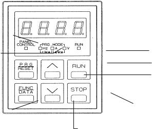
(1) Keypad Part Names and Functions
Operation Mode Indicator |
|
|
|
|
|
|
|
|
Digital Display |
||
|
|
|
|
|
|
|
|
||||
|
|
|
|
|
|
|
|
Unit Display |
|||
|
|
|
|
|
|
|
|
|
|
||
|
|
|
|
|
|
|
|
|
|
||
Program Mode |
|
|
|
|
|
|
|
|
Drive RUN Indicator |
||
Program/Reset Key |
|
|
|
|
|
|
|
|
RUN Key |
||
|
|
|
|
|
|
|
|
UP Key |
|||
|
|
|
|
|
|
|
|
||||
|
|
|
|
|
|
|
|
|
|
||
Function Key (Data Key) |
|
|
|
|
|
|
|
|
|
|
STOP Key |
|
|
|
|
|
|
|
|
|
|
||
|
|
|
|
|
DOWN Key |
||||||
|
|
|
|
|
|||||||
|
|
|
|
|
|
||||||
Digital Display (4 digits) -
Displays the various Function Codes and data values during setting of the program. During operation, it displays the output frequency, current, voltage, etc. If a fault occurs the cause of the problem will be displayed as a code.
PROGRAM Key (Reset Key) -
Normal mode or program setting mode select key. When any of the protection functions are activated; this key is used to reset the fault.
FUNCTION Key (Data Key) -
During the normal mode, this key can be used to change the display unit while operation is either stopped or running.
During the program mode, this key can be used to read and write the Function Codes and the data.
RUN Key - Key used for starting operation. The LED (green) lights up during operation.
This key does not function when terminal operation control is selected.
|
F |
|
0 |
2 |
= |
|
|
|
1 |
or |
|
|
|
|
|
|
|
|
|
|
|
|
|
|
|||||
F |
|
0 |
2 |
= |
|
|
|
2 |
|
STOP Key - This key is used for stopping drive operation. When set as follows:
F |
|
0 |
2 |
= |
|
|
|
0 |
|
|
|
|
|
|
|
|
|
operation command input is accepted from the Keypad (RUN and STOP keys).
When function 2 is set to 1:
F |
|
0 |
2 |
= |
|
|
|
1 |
|
|
|
|
|
|
|
|
|
Operation command input by means of the external signal terminal (FWD, REV). STOP key on the keypad is active. If selection "1" is chosen, and the stop button is depressed while the drive is running, the drive will perform the normal stop sequence until the output frequency reaches zero at which point an "Er6" fault shall be indicated on the LED. To reset the
drive you must remove the RUN command and press RESET. When function 2 is set to 2:
F |
|
0 |
2 |
= |
|
|
|
2 |
|
|
|
|
|
|
|
|
|
operation command input is accepted by means of the external signal terminal (FWD, REV). STOP key on the keypad is inactive.
UP / DOWN Keys - These keys increase or decrease the frequency reference. When unit is in program setting mode, they change the Function Code or data values.
Unit Display - Unit information is displayed by the LED (red). All three LEDs flash to indicate that the unit is in the program mode.
Operation Mode Indicator -
The LED (green) lights up when keypad panel operation is selected.
Drive RUN Indicator -
The LED (green) lights up in the RUN mode.
2-2
(2) Controlling Method for Keypad Panel
When the power supply is activated, the keypad panel display will be as shown in the figure on the right (60.00 FLASHING).
If the |
RUN |
key is pressed, the Drive will start and accelerate up to 60 Hz |
|
according to the factory setting. Use the STOP key to stop operation.
WARNING-RUNandSTOPkeysfunctiononlyinKeypadoperationmode.(FunctionCodeF_02settingis0)
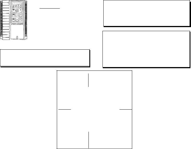
DriveComponents
5
1
3 |
1. |
Unit Cover (Middle) |
|
2. |
Unit Cover (Top) |
|
3. |
Keypad Panel (Optional) |
|
4. |
Heat Sink and Mounting Tabs |
|
5. |
Mounting Screw Holes |
|
6. |
Top Cover Screw |
2
6
4
Figure 2-3. TYPICAL DRIVE COMPONENTS
NOTE: NEMA 1 unit does not include keypad. Keypad is sold separately.
Keypad type is 6KM$2KP1 for NEMA 1 unit.
2-3
|
|
|
TABLE 1: Standard Specifications |
|
|
|
|
|
|
|
ITEM |
|
SPECIFICATION |
|
|
|
|
|
|
|
|
|
|
|
|
|
|
|
|
|
Environmental Conditions |
|
|
|
|
|
|
Enclosure |
|
NEMA 1or NEMA 4 |
|
|
|
|
|
|
|
|
|
|
|
|
|
|
|
InstallationLocation:NEMA1 |
|
Suitable for indoor mounting only, less than 1000 meters (3281 feet) elevation, |
|
|
|
|
|
|
|
|
not in contact with corrosive gas, oil mist, or dust. |
|
|
|
|
|
|
NEMA4 |
|
Suitable for use indoors or outdoors to protect the enclosed equipment against |
|
|
|
|
|
|
|
|
splashing water, seepage of water, falling or hose directed water and severe |
|
|
|
|
|
|
|
|
external condensation. Installation should be less than 1000 meters (3281 feet) |
|
|
|
|
|
|
|
|
elevation, not in contact with corrosive gas, or oil mist. |
|
|
|
|
|
|
|
|
|
|
|
|
|
|
|
StoredTemperature |
|
-20° to +65°C (-4° to +149°F) |
|
|
|
|
|
|
|
|
|
|
|
|
|
|
|
AmbientTemperature |
|
-10° to +50°C (+14° to +122° F) (remove ventilation covers if temperature is |
|
|
|
|
|
|
|
|
over (+40°C +104° F) |
|
|
|
|
|
|
|
|
|
|
|
|
|
|
|
Humidity |
|
20% to 95% relative humidity (non-condensing) |
|
|
|
|
|
|
|
|
|
|
|
|
|
|
|
Vibration |
|
0.6G or less |
|
|
|
|
|
|
|
|
|
|
|
|
|
|
|
CoolingMethod |
|
1/4 to 1 HP – Convection |
|
|
|
|
|
|
|
|
2 HP and greater – Forced air (Integral fan) |
|
|
|
|
|
|
|
|
|
|
|
|
|
|
|
|
|
Output |
|
|
|
|
|
|
|
|
|
|
|
|
|
|
|
RatedOutputVoltage |
|
3-Phase, 3-Wire, 80-240 VAC or 160-480 VAC |
|
|
|
|
|
|
|
|
(Can not exceed power supply voltage) |
|
|
|
|
|
|
|
|
|
|
|
|
|
|
|
FrequencyRange |
|
0 - 400 Hertz (0.2 to 15 Hz Start Frequency; 15 to 400 Hz Base Frequency) |
|
|
|
|
|
|
|
|
Above 120 Hz, contact the motor manufacturer for approval of application |
|
|
|
|
|
|
|
|
|
|
|
|
|
|
|
OverloadCurrentRating |
|
150% for 1 minute duration (inverse time characteristic) |
|
|
|
|
|
|
|
|
200% for 0.5 seconds |
|
|
|
|
|
|
|
|
|
|
|
|
|
|
|
|
|
Power Supply |
|
|
|
|
|
|
|
|
|
|
|
|
|
|
|
RatedInputACVoltage |
|
– 200 to 240 VAC 50/60 Hz, 1 phase (1/4 to 3 HP) |
|
|
|
|
|
|
|
|
– 200 to 230 VAC 50/60 Hz, 3 phase (1/4 to 5 HP) |
|
|
|
|
|
|
|
|
– 380 to 480 VAC 50/60 Hz, 3 phase (1/2 to 5 HP) |
|
|
|
|
|
|
|
|
Voltage: +10% to -15%; Voltage Unbalance: Within 3%; Frequency ±5% |
|
|
|
|
|
|
|
|
|
|
|
|
|
|
|
ControlSystem |
|
Sinusoidal PWM "TORQUE VECTOR" Control |
|
|
|
|
|
|
|
|
|
|
|
|
|
|
|
|
|
Control |
|
|
|
|
|
|
|
|
|
|
|
|
|
|
|
FrequencySetting |
|
– Analog: 0.02 Hz step at Maximum frequency of 60 Hz |
|
|
|
|
|
|
Resolution |
|
– Digital Keypad: 0.01 Hz Maximum frequency up to 99.99 Hz; 0.1 Hz (100 |
|
|
|
|
|
|
|
|
Hz or more) |
|
|
|
|
|
|
|
|
|
|
|
|
|
|
|
Accuracy(Stability) |
|
Analog setting: ± 0.2% of Maximum frequency (59° to 95° F) |
|
|
|
|
|
|
|
|
Digital Keypad setting: ± 0.01% of Maximum frequency (14° to 122° F) |
|
|
|
|
|
|
|
|
|
|
|
|
|
2-4
|
|
|
ITEM |
SPECIFICATION |
|||||
|
|
|
|
|
|
|
|
|
|
|
|
|
|
Control (continued) |
|||||
|
|
|
|
|
|
||||
|
|
|
Voltage/Frequency |
Voltage - 80-240 VAC or 160-480 VAC |
|||||
|
|
|
Characteristics(V/F) |
Frequency - 0.2 to 400 Hz |
|||||
|
|
|
|
|
|
|
|
|
|
|
|
|
TorqueBoost |
0: Automatic torque boost or 1 to 31.0 code settings (includes selection for |
|||||
|
|
|
|
variable torque load) |
|||||
|
|
|
|
|
|
|
|
|
|
|
|
|
Acceleration/Deceleration |
0.01 to 3600 seconds (independent acceleration/deceleration) |
|||||
|
|
|
Characteristics |
Alternative accel/decel time available as well as linear or 2 S-curves (selectable) |
|||||
|
|
|
|
|
|
|
|
||
|
|
|
MotorSound |
The pitch of the motor sound can be changed by selecting Carrier frequency |
|||||
|
|
|
|
(F_12: 0 to 15) |
|||||
|
|
|
|
|
|
|
|
||
|
|
|
FrequencyMeterAdjustment |
Scale calibration of externally connected analog meter or pulse |
|||||
|
|
|
|
frequency |
|||||
|
|
|
|
|
|
|
|||
|
|
|
DataProtection |
Data lock is possible to ensure that the function codes are not changed |
|||||
|
|
|
|
|
|
||||
|
|
|
High/LowFrequencyLimiter |
Output frequency upper and lower range limit 0 to 400 Hz; 1 Hz step settings |
|||||
|
|
|
|
|
|
||||
|
|
|
Bias |
Magnitude of the zero offset can be set from 0 to ±100% of maximum |
|||||
|
|
|
|
frequency (1Hz steps) |
|||||
|
|
|
|
|
|
||||
|
|
|
Gain |
Output frequency gain corresponding to the reference signal can be |
|||||
|
|
|
|
set from 0 to 250% |
|||||
|
|
|
|
|
|
||||
|
|
|
15StepPresetSpeed |
15 programmable preset speeds selectable by 4 contact closures |
|||||
|
|
|
|
|
|
||||
|
|
|
MaintainedContactOperation |
Maintained contact operation/stop command (2-wire operation) |
|||||
|
|
|
|
|
|
||||
|
|
|
TerminalFunctionChange |
Multi-Use terminal changed via Function Code settings (X4 input; Y1 output) |
|||||
|
|
|
|
|
|
||||
|
|
|
|
Operation |
|||||
|
|
|
|
|
|||||
|
|
|
FrequencyReferenceSignal |
Speed potentiometer: 0 to +10 VDC 4 to 20 mA [(0 to +5VDC) gain adjust 0-250%] |
|||||
|
|
|
|
|
|
||||
|
|
|
InputSignal(contacttype) |
Forward, reverse, multistep speed setting, alternate accel/decel time settings, |
|||||
|
|
|
|
coast-to-stop, external alarm, 3-wire control and reset |
|||||
|
|
|
|
|
|
||||
|
|
|
ExternalOutputSignals |
One Dry Form "C" alarm output contact rated 250 VAC, 0.3 amp |
|||||
|
|
|
|
1 – Open collector output rated 27 VDC, 50mA from external power |
|||||
|
|
|
|
– Drive Run – FDT – FAR – LV– TL – Auto restart mode after momentary |
|||||
|
|
|
|
power loss (IP) |
|||||
|
|
|
|
|
|
||||
|
|
|
FrequencyMeterOutputSignal |
Pulse frequency (adjustment to 6 kHz maximum) |
|||||
|
|
|
|
Analog - 0 to +10 VDC (adjustment range of 6.5 to 10.3 VDC) |
|||||
|
|
|
|
|
|
|
|
|
|
2-5
|
|
|
ITEM |
|
SPECIFICATION |
|
||
|
|
|
|
|
|
|
|
|
|
|
|
|
Operation (continued) |
|
|||
|
|
|
|
|
|
|
|
|
|
|
|
ProtectiveFunctions: |
– Stall prevention |
– Undervoltage |
|
||
|
|
|
|
– Surge input |
– Overcurrent |
|
||
|
|
|
|
– Drive overheating |
– Overvoltage |
|
||
|
|
|
|
– External faults |
– Short circuit for output terminals |
|
||
|
|
|
|
– CPU malfunction |
– Communication error |
|
||
|
|
|
|
– Motor overload |
– Ground fault (at start) |
|
||
|
|
|
|
(electronic thermal) |
– Output wiring not connected |
|
||
|
|
|
|
– Memory error |
(during auto tuning only) |
|
||
|
|
|
|
|
|
|
|
|
|
|
|
Keypad |
Digital Display - 4 digit LED |
|
|
|
|
|
|
|
|
|
|
|
||
|
|
|
DriveOperation |
Output frequency, output current, output voltage, motor speed, line speed |
|
|||
|
|
|
|
(m/min), machine speed (r/min) can be displayed |
|
|||
|
|
|
|
|
|
|||
|
|
|
DriveSetting |
Function Code and Setting Data can be displayed |
|
|||
|
|
|
|
|
|
|||
|
|
|
DataInitializing |
Resets all Function Codes to initial factory settings |
|
|||
|
|
|
DriveFault |
– OC1 - Acceleration overcurrent |
|
|||
|
|
|
|
– OC2 - Deceleration overcurrent |
|
|||
|
|
|
|
– OC3 - Constant speed overcurrent |
|
|||
|
|
|
|
– LU (LV) - Undervoltage |
|
|
|
|
|
|
|
|
– OU1 - Overvoltage during acceleration |
|
|||
|
|
|
|
– OU2 - Overvoltage during deceleration |
|
|||
|
|
|
|
– OU3 - Overvoltage at constant speed |
|
|||
|
|
|
|
– OH1 - Drive overheat |
|
|
|
|
|
|
|
|
– OH2 - External alarm input |
|
|
|
|
|
|
|
|
– OLU - Electronic Overload - Semiconductor Overload Protection |
|
|||
|
|
|
|
– OL - Electronic Overload - 4 Pole Motor Overload Protection |
|
|||
|
|
|
|
– Er1 - Setting error |
|
|
|
|
|
|
|
|
– Er2 - Communication error |
|
|
|
|
|
|
|
|
– Er3 - CPU error |
|
|
|
|
|
|
|
|
– Er4 - Optional circuit board communication error with Drive |
|
|||
|
|
|
|
– Er5 - Optional Problem - when a link error etc. is detected |
|
|||
|
|
|
|
– Er6 - Operating Proc. error |
|
|
|
|
|
|
|
|
– Er7 - Output wiring error |
|
|
|
|
|
|
|
Charge"CRG"Lamp(LED) |
Illuminates when DC Link capacitor voltage is present |
|
|||
|
|
|
|
|
|
|
|
|
2-6

|
Table 2: |
|
Drive Dimensions |
|
|
|
|
|
|||||
|
|
|
|
|
|
|
|
|
|
|
|
|
|
|
|
|
240 Volt – Single Phase |
|
|
|
|
||||||
|
|
HP |
|
Weight |
Height |
|
Width |
Depth |
Dim. Figure |
||||
Model |
Const |
|
LBS |
KGS |
Inches |
MM |
|
Inches |
MM |
Inches |
MM |
Pages |
|
NEMA 1 |
NEMA 4 |
TRQ |
|
|
|
|
|
|
|
|
|
|
3-2 to 3-5 |
6KM$221F25N1A1 |
6KM$221F25X4A1 |
1/4 |
|
2.7 |
1.2 |
6.22 |
158 |
|
4.29 |
109 |
3.15 |
80 |
1 and 4 |
6KM$221F50N1A1 |
6KM$221F50X4A1 |
1/2 |
|
3.8 |
1.7 |
6.22 |
158 |
|
5.67 |
144 |
4.29 |
109 |
2 and 6 |
6KM$221001N1A1 |
6KM$221001X4A1 |
1 |
|
4.0 |
1.8 |
6.22 |
158 |
|
5.67 |
144 |
4.29 |
109 |
2 and 6 |
6KM$221002N1A1 |
6KM$221002X4A1 |
2 |
|
6.2 |
2.8 |
6.22 |
158 |
|
8.03 |
204 |
5.28 |
134 |
3 and 8 |
6KM$221003N1A1 |
6KM$221003X4A1 |
3 |
|
6.4 |
2.9 |
6.22 |
158 |
|
8.03 |
204 |
5.28 |
134 |
3 and 8 |
|
|
|
|
230 Volt – Three Phase |
|
|
|
|
|
||||
6KM$223F25N1A1 |
6KM$223F25X4A1 |
1/4 |
|
2.4 |
1.1 |
6.22 |
158 |
|
4.29 |
109 |
3.15 |
80 |
1 and 4 |
6KM$223F50N1A1 |
6KM$223F50X4A1 |
1/2 |
|
2.9 |
1.3 |
6.22 |
158 |
|
4.29 |
109 |
3.54 |
90 |
1 and 5 |
6KM$223001N1A1 |
6KM$223001X4A1 |
1 |
|
3.3 |
1.5 |
6.22 |
158 |
|
4.29 |
109 |
4.69 |
119 |
1 and 7 |
6KM$223002N1A1 |
6KM$223002X4A1 |
2 |
|
4.6 |
2.1 |
6.22 |
158 |
|
5.67 |
144 |
4.69 |
119 |
2 and 7 |
36KM$223003N1A1 |
6KM$223003X4A1 |
3 |
|
6.2 |
2.8 |
6.22 |
158 |
|
8.03 |
204 |
5.28 |
134 |
3 and 8 |
36KM$223005N1A1 |
6KM$223005X4A1 |
5 |
|
7.0 |
3.3 |
6.22 |
158 |
|
8.03 |
204 |
5.87 |
149 |
3 and 9 |
|
|
|
|
480 Volt – Three Phase |
|
|
|
|
|
||||
6KM$243F50N1A1 |
6KM$243F50X4A1 |
1/2 |
|
4.2 |
1.9 |
6.22 |
158 |
|
5.67 |
144 |
4.29 |
109 |
2 and 6 |
6KM$243001N1A1 |
6KM$243001X4A1 |
1 |
|
4.2 |
1.9 |
6.22 |
158 |
|
5.67 |
144 |
4.29 |
109 |
2 and 6 |
6KM$243002N1A1 |
6KM$243002X4A1 |
2 |
|
6.2 |
2.8 |
6.22 |
158 |
|
8.03 |
204 |
5.28 |
134 |
3 and 8 |
6KM$243003N1A1 |
6KM$243003X4A1 |
3 |
|
6.2 |
2.8 |
6.22 |
158 |
|
8.03 |
204 |
5.28 |
134 |
3 and 8 |
6KM$243005N1A1 |
6KM$243005X4A1 |
5 |
|
7 |
3.3 |
6.22 |
158 |
|
8.03 |
204 |
5.87 |
149 |
3 and 9 |
|
|
Table 3: |
Drive Rating Efficiency and Watts Loss Table |
|
|
||||||
|
|
|
240 Volt – Single Phase |
|
|
|
|
||||
|
|
|
|
|
Output Current |
Output |
Efficiency |
|
|
||
|
Model |
HP |
|
Carrier Frequency |
Power |
Percentage |
Watts Loss |
||||
NEMA 1 |
|
NEMA 4 |
|
Low |
High |
KW |
Low |
High |
Low |
High |
|
6KM$221F25N1A1 |
6KM$221F25X4A1 |
1/4 |
|
1.5 |
1.3 |
0.19 |
87.6 |
80.9 |
27 |
45 |
|
6KM$221F50N1A1 |
6KM$221F50X4A1 |
1/2 |
|
3.0 |
2.5 |
0.37 |
88.1 |
83.2 |
50 |
75 |
|
6KM$221001N1A1 |
6KM$221001X4A1 |
1 |
|
5.0 |
4.0 |
0.75 |
90.4 |
88.8 |
80 |
95 |
|
6KM$221002N1A1 |
6KM$221002X4A1 |
2 |
|
8.0 |
7.0 |
1.50 |
92.9 |
91.5 |
115 |
140 |
|
6KM$221003N1A1 |
6KM$221003X4A1 |
3 |
|
11.0 |
10.0 |
2.20 |
93.6 |
92.4 |
150 |
180 |
|
|
|
|
|
230 Volt – Three Phase |
|
|
|
|
|||
6KM$223F25N1A1 |
6KM$223F25X4A1 |
1/4 |
|
1.5 |
1.3 |
0.20 |
87.6 |
80.9 |
27 |
45 |
|
6KM$223F50N1A1 |
6KM$223F50X4A1 |
1/2 |
|
3.0 |
2.5 |
0.40 |
88.1 |
83.2 |
50 |
75 |
|
6KM$223001N1A1 |
6KM$223001X4A1 |
1 |
|
5.0 |
4.0 |
0.75 |
90.4 |
88.8 |
80 |
95 |
|
6KM$223002N1A1 |
6KM$223002X4A1 |
2 |
|
8.0 |
7.0 |
1.50 |
92.9 |
91.5 |
115 |
140 |
|
36KM$223003N1A1 |
6KM$223003X4A1 |
3 |
|
11.0 |
10.0 |
2.20 |
93.6 |
92.4 |
150 |
180 |
|
36KM$223005N1A1 |
6KM$223005X4A1 |
5 |
|
17.0 |
16.5 |
3.70 |
94.6 |
93.4 |
212 |
260 |
|
|
|
|
|
480 Volt – Three Phase |
|
|
|
|
|||
6KM$243F50N1A1 |
6KM$243F50X4A1 |
1/2 |
|
1.6 |
1.4 |
0.37 |
86.0 |
79.9 |
60 |
93 |
|
6KM$243001N1A1 |
6KM$243001X4A1 |
1 |
|
2.5 |
2.1 |
0.75 |
90.4 |
86.9 |
80 |
113 |
|
6KM$243002N1A1 |
6KM$243002X4A1 |
2 |
|
3.7 |
3.7 |
1.50 |
93.2 |
88.1 |
110 |
203 |
|
6KM$243003N1A1 |
6KM$243003X4A1 |
3 |
|
5.5 |
5.3 |
2.20 |
94.4 |
89.4 |
130 |
260 |
|
6KM$243005N1A1 |
6KM$243005X4A1 |
5 |
|
9.0 |
8.7 |
3.70 |
94.9 |
91.0 |
200 |
366 |
|
NOTE: Carrier Frequency: High setting F_12 = 15
Low setting F_12 = 0
2-7
Section 3
INSTALLATION GUIDELINES
INSTALLATION ENVIRONMENT
Install the Drive in an indoor location that meets the following requirements:
—The ambient temperature is between -10° C and +50° C (+14° F to +122° F). Remove the ventilation covers when the temperature exceeds +40° C [+104° F].
—The relative humidity is between 20% and 95%. Avoid any location subject to condensation, freezing, or where the Drive would come in contact with water.
—Do not install in any location subject to direct sunlight, dust, corrosive gas, inflammable gas, or oil mist.
—Vibration should be less than 0.6G.
—The Drive should be installed at an elevation below 1000 meters (3281 feet). For installation above 1000 meters (3300 feet) the Drive will need to be derated 1% per 333 feet.
Example: 5 HP, 460 VAC, output current 9 amps. Application altitude 3900 feet.
% derate =(3900 - 3300 )x 1% = 1.8% 333
(100 - 1.8 )
(9 amps) x 100 = 8.84 amps derated output current.
Motor derate may also be required, contact motor manufacturer.
CAUTION: Because the ambient temperature greatly affects Drive life and reliability, do not install the Drive in any location that exceeds the allowable temperatures.
INSTALLATION MOUNTING
CLEARANCE
—Install at a sufficient distance from other equipment, walls, or wiring ducts as shown in Figure 3-1 (these clearances are required to allow the heat generated by the Drive to escape).
—Install the Drive perpendicular to the ground and with the lettering right side up. (If the Drive is installed upside-down or horizontally, heat buildup will occur.)
—Mounting screws or bolts should be of appropriate size for weight of Drive.
—See the appropriate figures on pages 3-2 and 3-3 for the location of mounting holes.
—After removing the knockouts in the wiring lead-in plate, install the rubber bushings supplied to prevent cable damage and to minimize dust entry.
CAUTION: The mounting wall for the Drive must be constructed of heat resistant material because during operation, the temperature of the Drive's cooling fins rises to approximately 90 degrees C (194° F).
NOTE: When installing two or more Drives in close proximity, allow sufficient space as shown in Figure 3-1 and install them in a horizontal row. If they must be installed in a vertical column, at least 19.7 inches (50cm) internal space must be provided between each one or a ventilation baffle should be provided to prevent the ambient temperature from rising.
5" or more
2"
or more
Figure 3-1.
2" or more
5" or more
DRIVE MOUNTING CLEARANCE
3-1
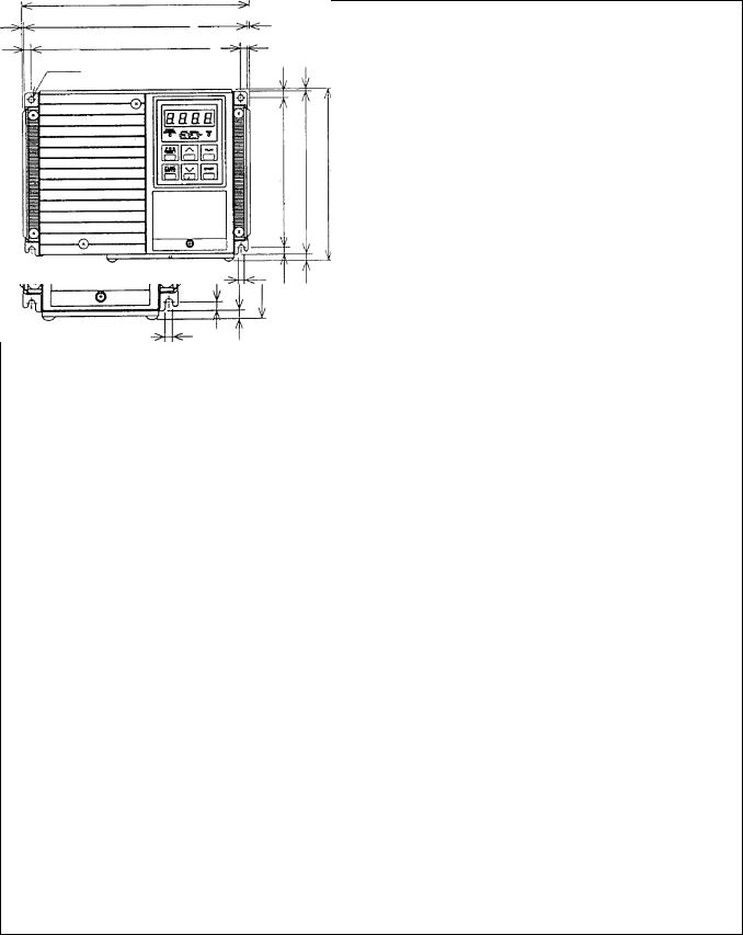
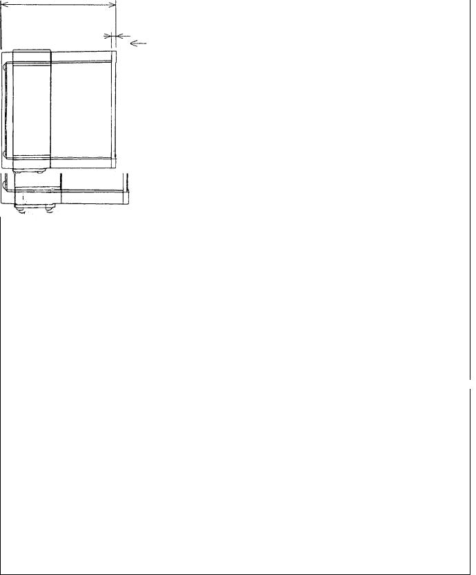
Dimensions
4.29 (109)
NOTE: NEMA 1 unit does not have Keypad.
Shown with optional Keypad
0.20 (5)
Figure 1
0.24 |
0.24 |
5.67 (144)
0.08(2)
0.24(6)
0.20 (5)
Figure 2
|
|
|
|
|
|
|
|
|
|
|
|
0.24 |
0.24 |
|
|
8.03 (204)
0.08(2)
0.24(6)
0.20 (5)
Figure 3
Note: Inches (MM)
0.24 (6) |
0.24 (6) |
3-2
|
|
Dimensions |
||||
|
|
4.29 (109) |
|
|
||
3.15 (80) |
|
3.54 (90) |
|
|
|
|
|
|
|
|
|
|
|
|
|
0.24 (6) |
|
|||
|
|
|
|
|
|
|
0.20 (5) |
|
|
|
|||
0.20 (5) |
|
|
|
|
||
|
|
|
|
|
|
|
Figure 4 |
Figure 5 |
Figure 6 |
5.28 (134)
4.69 (119)
0.24 (6) |
5.87 (149) |
|
0.24 (6)
0.24 (6)
Figure 7 |
Figure 8 |
Figure 9 |
Note: Inches (MM)
3-3
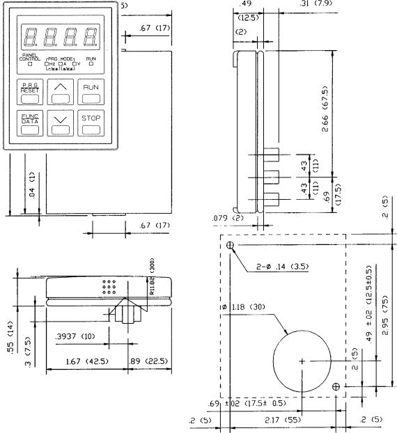
Dimensions of Keypad and Keypad Mounting Holes
|
|
|
Mounting Hole (panel cut-out) |
|
|
|
|
||
Keypad Part # |
6KM$2KP1 for NEMA 1 unit |
Inches (MM) |
||
|
|
6KM$2KP4 for NEMA 4 unit |
|
|
3-4

Section 4
WIRING PROCEDURES
Removing Top Cover
To access Main and Control Circuit Terminals remove the top cover as follows (see Figure 4-1):
1.Loosen the screw located at the bottom of the top cover.
2.Press upward on the bottom of the top cover (see arrows Figure 4-1 step 2) and lift off.
3.See Figure 4-1 for the location of the Main Circuit Terminal Block and the Control Circuit Terminal Block.
WARNING: Some printed circuit boards and Drive components may contain hazardous voltage levels. If LED light "CRG" on the Base Driver Board is illuminated, hazardous voltages are present in the Drive circuit boards. Remove and lock out power before you disconnect or reconnect wires, and before you remove or replace fuses and circuit boards. Do not attempt to service the Drive until the "CRG" indicator has extinguished and the bus voltage has discharged to zero volts.
Mounting Screw
Holes
Keypad Panel
Unit Cover (Middle)
Unit Cover (Top)
Top Cover Screw
Heat Sink
and Mounting Tabs
Step 1:
Loosen Top Cover
screw. (1 to 2 turns)
→ |
→ |
Teminal Block |
Step 2: |
|
|
Press Upward at the locations indicated by the arrows to remove the top cover.
Control
Circuit
Terminal
Block
Drive
Charge "CRG" Lamp
Figure 4-1. REMOVING THE TOP COVER
4-1
Control Circuit Wiring
Drive is wired at shipment for operation and frequency setting through the keypad panel (frequency is set at 60 Hz.)
–See Figure 4-2, and 4-4 for wiring connections.
–See TABLE 5 for description of all terminals.
Make wire connections as shown in Figure 4-4 through 4-6 for desired mode of external operation through Control Circuit Terminals.
CAUTION: The Control Circuit Terminal wiring should be kept as far away as possible from the main power wiring to prevent operational error due to noise interference. Never install both types of wiring in the same duct or conduit. (A separation distance of 4 inches [10 centimeters] or more is recommended.) If the control circuit wiring must cross the main power wiring, it should cross at a right angle.
CAUTION: Use shielded or twisted wire for the control circuit wiring (wiring should be as short as possible, i.e. 65 feet or less [20 meters.]) Connect outer covering of the shielded wires to the Drive ground terminal and leave the other end open, but taped with electrical insulating tape.
DC RELAY |
|
|
|
AC CONTACTOR |
|||
Figure 4-2. CONNECTION OF SURGE SUPPRESSION DEVICES
CAUTION: Install a suppressor in parallel with any relay or solenoid type coil as shown above, that may be close to the Drive to prevent noise from causing erratic Drive operation.
4-2
Main Circuit Wiring
CAUTION: Be sure that the power supply is never connected to the U, V, W terminals or the P (1), P (+), DB terminals.
1.Connect the ground terminal as shown in the appropriate view of Figure 4-3. (Do not operate without the unit being grounded.)
—The ground wire must be minimum 14 AWG and short as possible
2.Connect the power supply wires to the L1, L2, and L3 terminals of the Main Circuit Terminal Block as shown in the appropriate view of Figure 4-3. (See TABLE 5 for description of all terminals and TABLE 4 for recommended wire sizes.) Note that L1 and L2 terminals only, are available on single phase input models.
3.Connect the 3-phase motor wires to the U, V, and W terminals of the Main Circuit Terminal Block as shown in the appropriate view of Figure 4-3. (See TABLE 5 for description of all terminals and TABLE 4 for recommended wire sizes.)
4.Suitable for use on a circuit capable of delivering not more than 1000A (1 HP or less) or 5000A (2 HP or more) RMS symmetrical.
5.AC input fuses are to be customer supplied and may be branch circuit protection fuses. The maximum allowance fuse rating per TABLE 4.
NOTE: Motor will rotate counterclockwise when viewed from the shaft end when connected normally. If the motor rotates in reverse direction, interchange any two of the U, V, or W terminal connections.
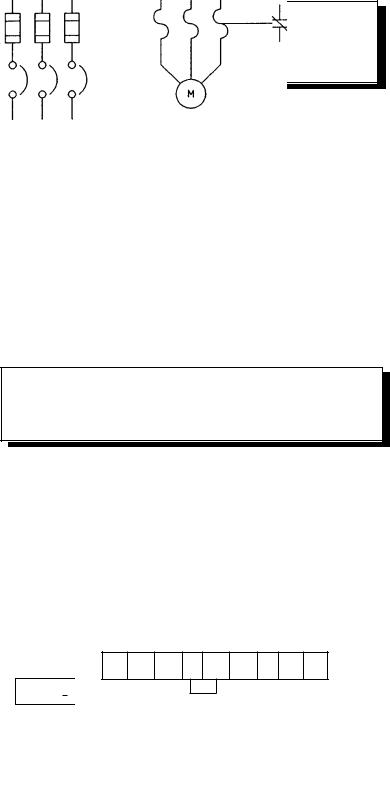
240V – Single Phase 1/4 to 3 HP
|
|
|
|
|
|
|
|
L1 |
L2 |
P1 |
P(+) |
DB* |
U |
V |
W |
||
|
|
|
|
|
|
|
|
|
|
|
|
|
|
|
|
|
|
|
|
|
|
|
|
|
|
|
|
|
|
|
|
||||
E (G) |
|
|
|
|
|
|
|
|
|
|
|
||||||
|
|
|
|
|
|
|
|
|
|
|
|
|
|
|
|
|
|
|
|
|
|
|
|
|
|
|
|
|
|
|
|
|
|
|
|
230 & 480V – Three Phase 1/4 to 5 HP
L1 L2 L3 P1 P(+) DB U V W
E (G) 

Fuses: Rating per TABLE 4 Reference UL power circuit
protection requirements.
CB
50/60 Hz, 3–Phase AC
Thermal Relay #
Motor
Factory installed jumper (Remove when installing DC Reactor)
* The DB resistor connection is not available on models 6KM$221F25X1A1, 6KM$221F25A4A1, 6KM$223F25X1A1, 6KM$223F25A4A1.
# Optional
Figure 4-3. MAIN CIRCUIT TERMINAL LAYOUT
4-3

Table 4:
Wire Size Recommendations
& Circuit Protection Ratings
240V – Single Phase and 230V Three Phase
|
|
|
|
|
|
|
DB |
Incoming Power |
|
Model |
PH |
HP |
Output Current |
Power |
Resistor** |
AC – Line Devices |
|||
NEMA 1 |
NEMA 4 |
|
Const |
Carrier Frequency |
Wire |
Wire |
|
Circuit |
|
|
|
Input |
TRQ |
Low |
High |
AWG |
AWG |
Fuses* |
Breaker |
6KM$221F25N1A1 |
6KM$221F25X4A1 |
1 |
1/4 |
1.5 |
1.3 |
16 |
- |
6 |
5 |
6KM$221F50N1A1 |
6KM$221F50X4A1 |
1 |
1/2 |
3 |
2.5 |
16 |
16 |
10 |
10 |
6KM$221001N1A1 |
6KM$221001X4A1 |
1 |
1 |
5 |
4 |
14 |
14 |
15 |
15 |
6KM$221002N1A1 |
6KM$221002X4A1 |
1 |
2 |
8 |
7 |
12 |
12 |
20 |
20 |
6KM$221003N1A1 |
6KM$221003X4A1 |
1 |
3 |
11 |
10 |
10 |
10 |
30 |
30 |
6KM$223F25N1A1 |
6KM$223F25X4A1 |
3 |
1/4 |
1.5 |
1.3 |
16 |
- |
6 |
5 |
6KM$223F50N1A1 |
6KM$223F50X4A1 |
3 |
1/2 |
3 |
2.5 |
16 |
16 |
10 |
5 |
6KM$223001N1A1 |
6KM$223001X4A1 |
3 |
1 |
5 |
4 |
16 |
16 |
15 |
10 |
6KM$223002N1A1 |
6KM$223002X4A1 |
3 |
2 |
8 |
7 |
14 |
14 |
20 |
15 |
6KM$223003N1A1 |
6KM$223003X4A1 |
3 |
3 |
11 |
10 |
14 |
14 |
30 |
20 |
6KM$223005N1A1 |
6KM$223005X4A1 |
3 |
5 |
17 |
16.5 |
10 |
10 |
40 |
30 |
|
|
|
|
|
|
|
|
|
|
480V – Three Phase
|
|
|
|
|
|
|
DB |
Incoming Power |
|
Model |
PH |
HP |
Output Current |
Power |
Resistor** |
AC – Line Devices |
|||
NEMA 1 |
NEMA 4 |
|
Const |
Carrier Frequency |
Wire |
Wire |
|
Circuit |
|
|
|
Input |
TRQ |
Low |
High |
AWG |
AWG |
Fuses* |
Breaker |
6KM$243F50N1A1 |
6KM$243F50X4A1 |
3 |
1/2 |
1.6 |
1.4 |
16 |
14 |
6 |
5 |
6KM$243001N1A1 |
6KM$243001X4A1 |
3 |
1 |
2.5 |
2.1 |
16 |
14 |
6 |
5 |
6KM$243002N1A1 |
6KM$243002X4A1 |
3 |
2 |
3.7 |
3.7 |
16 |
14 |
15 |
10 |
6KM$243003N1A1 |
6KM$243003X4A1 |
3 |
3 |
5.5 |
5.3 |
16 |
14 |
15 |
15 |
6KM$243005N1A1 |
6KM$243005X4A1 |
3 |
5 |
9.0 |
8.7 |
14 |
14 |
20 |
15 |
|
|
|
|
|
|
|
|
|
|
WARNING - Device ratings such as system coordination, short-circuit rating and type must be carefully reviewed by the user.
NOTE: Wire size from NEC table 310-16. Copper wire rated 60° C for 100 amps or less, 75° C for over 100 amps in 30° C ambient and 1.25 times Drive rated amps. These
are minimum wire sizes; consult and conform to local and national codes.
*NOTE: AC input fuses are required to validate the drive's UL and CSA approvals. The fuse should be Class J type such as Bussman, JKS or equivalent. Circuit breaker ratings are shown for reference, but UL and CSA approval can only be validated by the use of Class J fuses.
** Optional Item.
4-4

30A |
30B |
Y1 |
FMA |
PLC |
|
BX |
RST |
C1 |
13 |
12 |
11 |
||||||||||||||
|
|
|
|
|
|
|
|
|
|
|
|
|
|
|
|
|
|
|
|
|
|
|
|
|
|
|
30C |
FMP |
X1 |
X2 |
X3 |
|
X4 |
REV |
FWD |
THR |
CM |
#2 |
|||||||||||||
|
|
|
|
|
|
|
|
|
|
|
* |
|
* |
#1 |
|
|
|
||||||||
|
|
|
|
|
|
|
|
|
|
|
|
|
|
|
|
|
|
|
|
|
|
|
|
|
|
* Factory installed jumper
CONTROL CIRCUIT TERMINAL BLOCK LAYOUT
#1 CAUTION:
Remove jumper from between terminals THR and CM when a motor overload or a motor temperature switch is used. Wire the device thermal switch in series with the THR and CM terminals.
#2 NOTE:
FWD to CM jumper required for operation using keypad RUN-STOP.
Figure 4-4.
L1 L2 L3 P1 P(+) DB* U V W
|
|
|
|
|
|
|
|
|
|
|
|
|
|
|
|
|
|
|
|
|
|
|
|
|
|
|
|
|
|
|
|
|
|
|
|
|
|
|
|
|
|
|
|
|
|
|
|
|
|
|
|
|
|
|
|
|
|
|
|
|
|
|
|
|
|
|
|
DB |
|
|
|
E(G) |
|
|
|
|
|
|
|
|
|
|
|
|
|
|
|||
|
|
|
|
|
|
|
|
|
|
|
|
RESISTOR |
|
|
|||
|
|
|
|
|
|
|
|
|
|
|
|
|
|
||||
|
|
|
|
|
|
|
|
|
|
|
|
|
|
||||
|
|
|
|
|
|
|
|
|
|
|
|
|
|
||||
|
|
|
|
|
|
|
|
|
|
|
|
|
|
|
|
|
|
* Not available on 6KM$221F25X1A1, 6KM$221F25A4A1, 6KM$223F25X1A1, 6KM$223F25A4A1.
Figure 4-5. DYNAMIC BRAKING RESISTOR CONNECTIONS
4-5

DISCONNECT/ |
|
|
|
|
|
|
|
|
|
|
|
CIRCUIT |
# |
|
|||||||||
BREAKER # |
|
||||||||||
1 or 3PH |
|
|
|
|
|
|
|
|
|
|
|
50/60 Hz |
|
|
|
|
|
|
|
|
|
|
|
230/480 Vac |
|
|
|
|
|
|
|
|
|
|
|
(Based on |
|
|
|||||||||
Model selected) |
|
||||||||||
GROUND |
|||||||||||
|
|
|
|
|
|
|
|
|
|
||
FUSE |
|
|
|
|
|
|
|
|
|
|
|
DC REACTOR # |
|||||||||||
|
|||||||||||
|
P1 |
|
|
|
|
|
|
|
|
|
|
|
|
|
|
|
|
|
|
|
|
||
|
|
|
|
|
|
||||||
|
|
|
|
|
|
|
|
|
|
||
DO NOT CONNECT
TO CM
DIGITAL METER
BX
|
PLC |
RST |
|
X4(HLD) |
Y1 |
|
BRAKING RESISTOR
1/2 TO 5HP #
BRAKING RESISTOR
THERMAL SWITCH
ALARM RELAY OUTPUT
PROGRAMMABLE LOGIC
CONTROL POWER
ANY ADDITIONAL NORMALLY
CLOSED PROTECTIVE
INTERLOCKS SHOULD BE
ADDED IN SERIES
* Terminal 11 should not be connected to CM.
L3 not supplied on single phase units.
# Optional
Figure 4-6. WIRING DIAGRAM
CAUTION:
1.The Control Circuit Terminal wiring should be kept as far as possible from the main circuit wiring to prevent operation error due to noise interference. Never install them in the same duct or conduit. A separation distance of 4 inches or more is recommended. If the control circuit wiring must cross the main circuit wiring, make sure it crosses at a right angle.
2.Use shielded wire for the control circuit wiring, which should be as short as possible (66 feet or less). Connect shield to the Drive ground terminal and leave the other end open but taped.
3.Install a surge protector in parallel with any magnetic contactors, solenoids, relays or timer coils which are close to the Drive.
4-6

TABLE 5: Terminal Identification/Function
|
|
Terminal |
|
Terminal |
|
|
|
|
|
|
Label |
|
Name |
Function |
|||
|
|
|
|
|
|
|
||
|
|
|
|
|
|
POWER TERMINAL BOARD |
|
|
|
|
|
|
|
|
|
|
|
|
|
L1, L2, |
|
AC Supply Line |
Connection for 200-230 VAC or 380-480 VAC, 3-phase, 50/60 Hz; |
|||
|
|
L3 |
|
Input Terminals |
L1 & L2 for single phase input, 200-240 VAC 50/60 Hz |
|||
|
|
|
|
|
|
|
|
|
|
|
U, V, W |
|
Drive Output |
Connection for 3-phase induction motor |
|||
|
|
|
|
Terminals |
|
|
|
|
|
|
|
|
|
|
|
|
|
|
|
P+, DB |
|
External Braking |
Connection for external braking resistor option for single phase and |
|||
|
|
|
|
Resistor Terminals |
three phase drives (Only on 1⁄2 HP to 5 HP; not on 1/4 HP) |
|||
|
|
|
|
|
|
|
|
|
|
|
P1, P+ |
|
DC Reactor Terminals |
Connection for external DC reactor for power factor improvement |
|||
|
|
|
|
|
|
(Option). (Remove factory installed jumper) |
||
|
|
|
|
|
|
|
|
|
|
|
|
|
|
|
CONTROL TERMINAL BOARD |
||
|
|
|
|
|
|
|
|
|
|
|
11 |
|
Frequency Setting & |
Common connector for terminals 12, 13, C1 and FMA (Do not |
|
||
|
|
|
|
Analog Freq. Meter |
connect to CM terminal or electrical noise immunity may be lost). |
|||
|
|
|
|
Common Terminal |
|
|
|
|
|
|
|
|
|
|
|
|
|
|
|
12 |
|
Frequency Setting |
When 0 to +10 VDC (0 to 5V*) is applied, the maximum frequency is |
|||
|
|
|
|
Voltage Input |
reached at +10 VDC (5V*) and is proportional to output frequency |
|||
|
|
|
|
|
|
down to 0 VDC. Input impedance is 22K ohm ( *250% gain setting F_35) |
||
|
|
|
|
|
|
|
|
|
|
|
13 |
|
Frequency Setting |
Regulated +10 VDC power supply for frequency setting potentiometer, |
|||
|
|
|
|
Voltage Output Term. |
10mA or less (13 to terminal 11) |
|||
|
|
|
|
|
|
|
|
|
|
|
C1 |
|
Frequency Setting |
When the input signal is +4 to +20mA dc, the maximum frequency is |
|||
|
|
|
|
Current Input (+) |
reached at 20mA and is proportional down to a minimum frequency |
|||
|
|
|
|
|
|
setting at 4mA. Input impedance is 250 ohm, must be isolated source |
||
|
|
|
|
|
|
|
|
|
|
|
CM |
|
Control Circuit |
Common terminal for control input commands, X1-X4, FWD, REV, BX, |
|||
|
|
|
|
Common Terminal |
RST, THR, Y1 and FMP pulse output signal |
|||
|
|
|
|
|
|
(Do not connect to terminal 11) |
||
|
|
|
|
|
|
|
|
|
|
|
FWD |
|
Forward Command |
|
|
|
|
|
|
|
|
Input Terminal |
Forward command via FWD-CM (closed). Reverse command via |
|||
|
|
|
|
|
|
REV-CM (closed). When FWD-CM and REV-CM are closed |
||
|
|
|
|
|
|
|||
|
|
|
|
Reverse Command |
at the same time, the Drive will decelerate to stop |
|||
|
|
REV |
|
Input Terminal |
|
|
|
|
|
|
|
|
|
|
|
|
|
|
|
BX |
|
Motor Coast-To-Stop |
Motor will coast-to-stop with BX-CM (closed). (For use when |
|||
|
|
|
|
Command Input |
applying mechanical brake with Drive in operation.) Note: If BX-CM is |
|||
|
|
|
|
Terminal |
opened with FWD or REV closed, the Drive will start the motor |
|||
|
|
|
|
|
|
|
|
|
|
|
RST |
|
Fault Reset Input |
After removal of fault condition, Faults are reset when a momentary |
|||
|
|
|
|
Terminal |
contact closure is made between the RST-CM terminals for more |
|||
|
|
|
|
|
|
than 0.1 seconds |
||
|
|
|
|
|
|
|||
|
|
|
|
|
|
If there is an input to the FWD or REV terminals with F_02 = 1 OR |
||
|
|
|
|
|
|
2 and F_14 = 4 or 5 the Drive will suddenly restart. |
||
|
|
|
|
|
|
|||
|
|
|
|
|
|
|
|
|
|
|
|
|
|
|
|
|
|
4-7

TABLE 5: Terminal Identification/Function (continued)
|
|
Terminal |
Terminal |
|
|
|
|
|
|
|
|
|
|
Label |
Name |
|
Function |
||||||
|
|
|
|
|
|
|
|
|
|
|
|
|
|
|
|
CONTROL TERMINAL BOARD (Continued) |
|
||||||
|
|
THR |
External thermal trip |
|
With THR-CM (open), OH trip will occur and the motor will |
||||||
|
|
|
command |
|
coast-to-stop. |
|
|
|
|
|
|
|
|
|
|
|
NOTE: With no external thermal relay or external braking resistor |
||||||
|
|
|
|
|
thermostat, the THR-CM terminals must be closed or the Drive |
||||||
|
|
|
|
|
will not operate. THR-CM is factory pre-jumpered, remove prior to |
||||||
|
|
|
|
|
connecting an external NC contacts. |
|
|
|
|
|
|
|
|
|
|
|
|
|
|
|
|
||
|
|
FMA* |
Analog Frequency |
|
Provides an output of 0 to +10 VDC (+10VDC at max frequency), |
||||||
|
|
|
Meter Connection |
|
available for connection of a voltmeter with internal resistance of |
||||||
|
|
|
F_40=0 |
|
10K ohms. See Function Code 41 for monitoring selection. Meter |
||||||
|
|
|
|
|
connects between terminal FMA & 11. Note: FMP cannot be used |
||||||
|
|
|
|
|
|
|
|
|
|
||
|
|
FMP* |
Digital Frequency |
|
Pulse frequency output equal to Drive output frequency. |
||||||
|
|
|
Meter Connection |
|
Pulse voltage: Peak 5 VDC, 50% duty, Adjustable range = 600 to |
||||||
|
|
|
F_40=1 |
|
6000 Hz (Max) See Function Code 42 Pulse Rate Multiplier. |
||||||
|
|
|
|
|
Meter connects between FMP and CM. Note: FMA cannot be used |
||||||
|
|
|
|
|
|
|
|
|
|||
|
|
30A |
Fault Relay Output |
|
During normal operation, the relay is not energized and contact is made |
||||||
|
|
30B |
Terminals |
|
between 30B and 30C. When a fault is detected, the relay is energized |
||||||
|
|
30C |
|
|
and contact is made between 30A and 30C. (Contact rating resistive |
||||||
|
|
|
|
|
load: 250 VAC, 0.3 Amps) |
|
|
|
|
|
|
|
|
|
|
|
|
|
|
||||
|
|
X1-X3 |
Multistep Frequency |
|
Seven individual preset frequency selections via binary combination |
||||||
|
|
|
Input Function |
|
(closure) between X1, X2, X3, and CM. |
||||||
|
|
|
Selection |
|
Frequency selections determined using functions F_21 thru F_27. |
||||||
|
|
|
|
|
|
|
|
||||
|
|
X4 |
Function Extension |
|
F_43=0 acceleration/deceleration time #2 is selected when X4-CM is |
||||||
|
|
|
(Input) |
|
closed. When not closed #1 setting is activated. |
||||||
|
|
|
|
|
(F_43=1) 8 additional frequencies can be selected by X1, X2, X3 and X4. |
||||||
|
|
|
|
|
(F_43=2) 2nd Motor selection when X4 - CM is closed. |
||||||
|
|
|
|
|
(F_43=3) Functions as hold signal if 3-wire operation is desired. |
||||||
|
|
|
|
|
|
|
|||||
|
|
Y1 |
Output Function |
|
Outputs one of the following signals depending on setting of F_54; |
||||||
|
|
|
(Programmable) |
|
0: Drive running (RUN) |
3: Undervoltage stop mode (LV) |
|||||
|
|
|
|
|
1: Frequency level detection (FDT) |
4: Torque limiting mode (TL) |
|||||
|
|
|
|
|
2: Frequency equivalence (FAR) |
5: Auto restart mode after |
|||||
|
|
|
|
|
|
momentary power loss (IP) |
|||||
|
|
|
|
|
Allowable load: Maximum 27VDC, 50mA or less |
||||||
|
|
|
|
|
|
|
|||||
|
|
PLC |
PLC |
|
Prevents PLC fault caused by leakage current from the drive. (See Drive |
||||||
|
|
|
|
|
interface details, Figure 4-7) |
|
|
|
|
|
|
|
|
|
|
|
|
|
|
|
|
|
|
* Either an analog (FMA) or digital (FMP) frequency meter, not both.
4-8
 Loading...