


GE Healthcare
Aestiva/5
Operation Manual - Part 2
Software Revision 4.X
Setup, Cleaning, Maintenance, Troubleshooting

User Responsibility
This Product will perform in conformity with the description thereof contained in this Operation manual and accompanying labels and/or inserts, when assembled, operated, maintained, and repaired in accordance with the instructions provided. This Product must be checked periodically. A defective Product should not be used. Parts that are broken, missing, plainly worn, distorted, or contaminated should be replaced immediately. Should repair or replacement become necessary, Datex-Ohmeda recommends that a telephonic or written request for service advice be made to the nearest Datex-Ohmeda Customer Service Center. This Product or any of its parts should not be repaired other than in accordance with written instructions provided by Datex-Ohmeda and by Datex-Ohmeda trained personnel. The Product must not be altered without the prior written approval of Datex-Ohmeda. The user of this Product shall have the sole responsibility for any malfunction which results from improper use, faulty maintenance, improper repair, damage, or alteration by anyone other than Datex-Ohmeda.
w CAUTION U.S. Federal law restricts this device to sale by or on the order of a licensed medical practitioner. Outside the U.S.A., check local laws for any restriction that may apply.
Datex-Ohmeda products have unit serial numbers with coded logic which indicates a product group code, the year of manufacture, and a sequential unit number for identification.
AAA F 12345
This alpha character indicates the year of product manufacture and when the serial number was assigned; “D” = 2000, “E” = 2001, “F” = 2002, etc. “I” and “O” are not used.
Aestiva, S/5, PSVPro, Tec 5, Tec 6 and Tec 7 are registered trademarks of
Datex-Ohmeda Inc.
Other brand names or product names used in this manual are trademarks or registered trademarks of their respective holders.
Table of Contents
1/Introduction
How to use this manual . . . . . . . . . . . . . . . . . . . . . . . . . . . . . . . . . . . . . . . . . |
1-2 |
i |
|
|
|
Symbols used in the manual or on the equipment . . . . . . . . . . . . . . . . . . . . |
1-3 |
|
Maintenance summary and schedule . . . . . . . . . . . . . . . . . . . . . . . . . . . . . . |
1-6 |
|
Operator maintenance . . . . . . . . . . . . . . . . . . . . . . . . . . . . . . . . . . . . . . |
1-6 |
|
Datex-Ohmeda approved service . . . . . . . . . . . . . . . . . . . . . . . . . . . . . . |
1-7 |
|
2/Cleaning and Sterilization
Summary . . . . . . . . . . . . . . . . . . . . . . . . . . . . . . . . . . . . . . . . . . . . . . . . . . . . . 2-2
Patient path . . . . . . . . . . . . . . . . . . . . . . . . . . . . . . . . . . . . . . . . . . . . . . . 2-2
Scavenging path . . . . . . . . . . . . . . . . . . . . . . . . . . . . . . . . . . . . . . . . . . . 2-3
Clean and sterilize . . . . . . . . . . . . . . . . . . . . . . . . . . . . . . . . . . . . . . . . . . . . . . 2-4
To wash (by hand or machine) . . . . . . . . . . . . . . . . . . . . . . . . . . . . . . . . 2-4
Autoclave . . . . . . . . . . . . . . . . . . . . . . . . . . . . . . . . . . . . . . . . . . . . . . . . . 2-5
Special requirements . . . . . . . . . . . . . . . . . . . . . . . . . . . . . . . . . . . . . . . 2-6
Assemble . . . . . . . . . . . . . . . . . . . . . . . . . . . . . . . . . . . . . . . . . . . . . . . . . 2-6
Disassemble the patient path . . . . . . . . . . . . . . . . . . . . . . . . . . . . . . . . . . . . 2-7
Canister disassembly . . . . . . . . . . . . . . . . . . . . . . . . . . . . . . . . . . . . . . . . . .2-10
Disassemble the scavenging path . . . . . . . . . . . . . . . . . . . . . . . . . . . . . . . .2-12
How to clean and disinfect the flow sensors . . . . . . . . . . . . . . . . . . . . . . . .2-13
How to clean and sterilize the optional CO2 bypass assembly . . . . . . . . .2-15
3/Setup and Connections
Breathing system setup . . . . . . . . . . . . . . . . . . . . . . . . . . . . . . . . . . . . . . . . . 3-2
Canister setup . . . . . . . . . . . . . . . . . . . . . . . . . . . . . . . . . . . . . . . . . . . . . . . . . 3-6
Pneumatic and electrical connections . . . . . . . . . . . . . . . . . . . . . . . . . . . . . 3-8
How to install gas cylinders (high-pressure leak test) . . . . . . . . . . . . . . . .3-11
Cylinder yokes . . . . . . . . . . . . . . . . . . . . . . . . . . . . . . . . . . . . . . . . . . . .3-11
DIN connections . . . . . . . . . . . . . . . . . . . . . . . . . . . . . . . . . . . . . . . . . .3-12
How to install the gooseneck lamp (12 V) . . . . . . . . . . . . . . . . . . . . . . . . . .3-14
How to attach equipment to the top shelves . . . . . . . . . . . . . . . . . . . . . . .3-15
How to install equipment on the foldout shelf . . . . . . . . . . . . . . . . . . . . . .3-17
Installation notes . . . . . . . . . . . . . . . . . . . . . . . . . . . . . . . . . . . . . . . . . . . . .3-18
1006-0939-000 |
i |
Aestiva
4/User Maintenance
ii
Repair policy . . . . . . . . . . . . . . . . . . . . . . . . . . . . . . . . . . . . . . . . . . . . . . . . . .4-2 Manifold maintenance . . . . . . . . . . . . . . . . . . . . . . . . . . . . . . . . . . . . . . . . . .4-3 Expiratory valve maintenance . . . . . . . . . . . . . . . . . . . . . . . . . . . . . . . . . . . . .4-6 Receiver maintenance (active gas scavenging only) . . . . . . . . . . . . . . . . . .4-8 Flow sensor maintenance . . . . . . . . . . . . . . . . . . . . . . . . . . . . . . . . . . . . . . . .4-9 Breathing circuit maintenance . . . . . . . . . . . . . . . . . . . . . . . . . . . . . . . . . . 4-10 Bellows maintenance . . . . . . . . . . . . . . . . . . . . . . . . . . . . . . . . . . . . . . . . . 4-12 Bellows tests . . . . . . . . . . . . . . . . . . . . . . . . . . . . . . . . . . . . . . . . . . . . . . . . 4-15 O2 sensor calibration - 21% O2 . . . . . . . . . . . . . . . . . . . . . . . . . . . . . . . . . 4-18 O2 sensor calibration - 100% O2 . . . . . . . . . . . . . . . . . . . . . . . . . . . . . . . . 4-21 Flow sensor calibration . . . . . . . . . . . . . . . . . . . . . . . . . . . . . . . . . . . . . . . . 4-24 How to prevent water build-up . . . . . . . . . . . . . . . . . . . . . . . . . . . . . . . . . . 4-25
5/Alarms and Troubleshooting
About alarms . . . . . . . . . . . . . . . . . . . . . . . . . . . . . . . . . . . . . . . . . . . . . . . . . .5-2
Alphabetical list . . . . . . . . . . . . . . . . . . . . . . . . . . . . . . . . . . . . . . . . . . . . . . . .5-4
Breathing system problems (no alarm) . . . . . . . . . . . . . . . . . . . . . . . . . . . 5-15
Electrical problems (power failure, etc.) . . . . . . . . . . . . . . . . . . . . . . . . . . 5-16
Pneumatic problems . . . . . . . . . . . . . . . . . . . . . . . . . . . . . . . . . . . . . . . . . . 5-18
6/Illustrated Parts
Breathing system parts . . . . . . . . . . . . . . . . . . . . . . . . . . . . . . . . . . . . . . . . |
. .6-2 |
Top level . . . . . . . . . . . . . . . . . . . . . . . . . . . . . . . . . . . . . . . . . . . . . . . . |
. .6-2 |
Main manifold . . . . . . . . . . . . . . . . . . . . . . . . . . . . . . . . . . . . . . . . . . . . . . . . |
.6-5 |
Exhalation valve . . . . . . . . . . . . . . . . . . . . . . . . . . . . . . . . . . . . . . . . . . . . . . . |
.6-7 |
Bellows . . . . . . . . . . . . . . . . . . . . . . . . . . . . . . . . . . . . . . . . . . . . . . . . . . . . . . |
.6-9 |
Test tools and system parts . . . . . . . . . . . . . . . . . . . . . . . . . . . . . . . . . . . . |
6-10 |
7/Theory of Operation and Specifications
Ventilator Theory . . . . . . . . . . . . . . . . . . . . . . . . . . . . . . . . . . . . . . . . . . . . . . .7-2
Modes . . . . . . . . . . . . . . . . . . . . . . . . . . . . . . . . . . . . . . . . . . . . . . . . . . . .7-3
ii |
1006-0939-000 |
Table of Contents
Breathing system schematic . . . . . . . . . . . . . . . . . . . . . . . . . . . . . . . . |
. 7-7 |
Electrical block diagram |
iii |
. 7-8 |
|
Pneumatic circuits . . . . . . . . . . . . . . . . . . . . . . . . . . . . . . . . . . . . . . . . . . . . |
. 7-9 |
Suction regulators (optional) . . . . . . . . . . . . . . . . . . . . . . . . . . . . . . . . . . . . |
7-12 |
O2 flowmeter (optional) . . . . . . . . . . . . . . . . . . . . . . . . . . . . . . . . . . . . . . . . . |
7-12 |
Breathing system . . . . . . . . . . . . . . . . . . . . . . . . . . . . . . . . . . . . . . . . . . . . . . |
7-13 |
Breathing system specifications . . . . . . . . . . . . . . . . . . . . . . . . . . . . . . . . . |
7-15 |
Pneumatic specifications . . . . . . . . . . . . . . . . . . . . . . . . . . . . . . . . . . . . . . . |
7-17 |
Flow specifications . . . . . . . . . . . . . . . . . . . . . . . . . . . . . . . . . . . . . . . . . . . . |
7-18 |
Electrical power . . . . . . . . . . . . . . . . . . . . . . . . . . . . . . . . . . . . . . . . . . . . . . . |
7-19 |
Power cord . . . . . . . . . . . . . . . . . . . . . . . . . . . . . . . . . . . . . . . . . . . . . . . |
7-20 |
Electrical fuses . . . . . . . . . . . . . . . . . . . . . . . . . . . . . . . . . . . . . . . . . . . |
7-20 |
Battery information . . . . . . . . . . . . . . . . . . . . . . . . . . . . . . . . . . . . . . . . |
7-20 |
Electro-magnetic compatibility . . . . . . . . . . . . . . . . . . . . . . . . . . . . . . |
7-20 |
Physical specifications . . . . . . . . . . . . . . . . . . . . . . . . . . . . . . . . . . . . . . . . . |
7-21 |
Environmental requirements . . . . . . . . . . . . . . . . . . . . . . . . . . . . . . . . . . . . |
7-22 |
Ventilation operating specifications. . . . . . . . . . . . . . . . . . . . . . . . . . . . . . . |
7-23 |
Aestiva ventilator accuracy data . . . . . . . . . . . . . . . . . . . . . . . . . . . . . . . . . |
7-25 |
Index
Warranty
1006-0939-000 |
iii |
Aestiva
iv
iv |
1006-0939-000 |
1 Introduction
1-1
In this section How to use this manual . . . . . . . . . . . . . . . . . . . . . . . . . . . . . . . . . . . . . . . . . . . . . . . . . 1-2 Symbols used in the manual or on the equipment . . . . . . . . . . . . . . . . . . . . . . . . . . . 1-3 Maintenance summary and schedule . . . . . . . . . . . . . . . . . . . . . . . . . . . . . . . . . . . . . . 1-6
1006-0939-000 |
1-1 |
Aestiva
How to use this manual
This is part two of the Aestiva operation and maintenance manual. It tells you how to:
•Remove and clean parts
•Set up the system
•Identify and replace worn or damaged parts
•Calibrate the O2 sensor
The second half of this section is a maintenance schedule.
The last section, troubleshooting, tells you what causes each alarm and what you can do about it.
Use this manual together with Part 1, which includes the operating instructions and preoperative checkout.
wWARNING If an alarm occurs, safeguard the patient first, before troubleshooting or repair procedures.
1-2 |
1006-0939-000 |
1 Introduction
Symbols used in the manual or on the equipment
wWarnings and wCautions tell you about dangerous conditions that can
occur if you do not follow all instructions in this manual.
1-3
Warnings tell about a condition that can cause injury to the operator or the patient.
Cautions tell about a condition that can cause damage to the equipment. Read and follow all warnings and cautions.
Other symbols replace words on the equipment or in Datex-Ohmeda manuals.
No one device or manual uses all of the symbols. These symbols include:
l |
On (power) |
|||
O |
Off (power) |
|||
o |
||||
Standby |
||||
|
|
|
||
q |
Standby or preparatory state for part of |
|||
the equipment |
||||
p |
“ON” only for part of the equipment |
|||
œ |
“OFF” only for part of the equipment |
|||
† |
||||
Direct current |
||||
|
|
|
||
~ |
|
Alternating current |
||
|
|
|
||
x |
Protective earth ground |
|||
|
|
|
||
|
|
|
Electrical input |
|
|
|
|
Pneumatic inlet |
|
|
|
|
||
|
|
|
||
r |
Frame or chassis ground |
|||
|
|
|
||
Í
m
µ
H w wW NN
y
REF
Not autoclavable
Type B equipment
Type BF equipment
Type CF equipment
Caution, ISO 7000-0434
Attention, refer to product instructions, IEC 601-1
This way up
Dangerous Voltage
Earth ground
Electrical output
Pneumatic outlet
Stock Number
1006-0939-000 |
1-3 |

Aestiva
å
Y
t
T
+
-
P
N
ˆ
z
Z
Alarm silence button |
SN |
Serial Number |
|
|
|
Equipotential |
|
Systems with this mark agree with |
|
|
the European Council Directive |
|
|
(93/42/EEC) for Medical Devices |
|
|
when they are used as specified in |
|
|
their Operation and Maintenance |
|
|
Manuals. The xxxx is the |
|
|
certification number of the |
|
|
Notified Body used by Datex- |
|
|
Ohmeda’s Quality Systems. |
Variability |
|
Read top of float |
Variability in steps |
|
Vacuum inlet |
Plus, positive polarity |
|
Suction bottle outlet |
Minus, negative polarity |
O2+ |
O2 Flush button |
Lamp, lighting, illumination |
|
Cylinder |
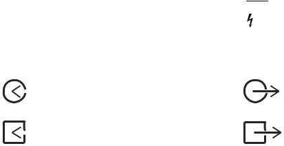
Movement in one direction |
|
Isolation transformer |
Movement in two directions |
|
Linkage system |
Lock |
|
Risk of Explosion |
Unlock |
|
Low pressure leak test |
1-4 |
1006-0939-000 |
134°C
R u q t
Autoclavable
Bag position/ manual ventilation
Open drain (remove liquid)
Inspiratory flow
O2 sensor connection
The primary regulator is set to pressure less than 345 kPa.
 European Union Representative
r U Q
1 Introduction
1-5
Mechanical ventilation
Close drain
Expiratory flow
End case
The primary regulator is set to pressure less than 414 kPa.
1006-0939-000 |
1-5 |

Aestiva
Maintenance summary and schedule
|
These schedules show the minimum frequency. You will have to service the |
|
|
equipment more frequently if you use it: |
|
|
• In unusual conditions (dirty gas supplies, high temperature, high humidity, |
|
|
etc.). |
|
|
• More frequently than normal. |
|
Operator maintenance |
Examine all components and do the maintenance procedures more frequently |
|
|
if necessary. |
|
|
Minimum |
|
|
Frequency |
Maintenance |
|
|
|
|
Daily |
• Clean the external surfaces. |
|
|
• 21% O2 calibration (circuit O2 sensor). |
|
|
• Flow sensor calibration |
|
|
|
|
Two weeks |
• Drain the vaporizers and discard the agent. This is not |
|
|
necessary for Tec 6 vaporizers. |
|
|
|
|
Monthly |
• 100% O2 calibration (cIrcuit O2 sensor). |
|
|
• Put Krytox (or a lubricant approved for use with 100% |
|
|
O2) on all tee handle threads. |
|
|
|
|
During cleaning |
• Inspect the parts for damage. Replace or repair as |
|
and setup |
necessary |
|
|
|
|
Annually |
• Replace the external o-rings on the vaporizer ports. |
|
|
|
|
As necessary |
• Install new cylinder gaskets on cylinder yokes. |
|
|
• Replace the absorbent in the absorber. |
|
|
• Drain the breathing system. |
• Drain the breathing circuit module.1
• Drain the overflow trap on the optional suction regulator.
• Replace the circuit O2 sensor.
• Replace the disposable flow sensors (plastic) 2
• Replace the autoclavable flow sensors (metal)3.
• Replace the receiver filter (active gas scavenging only).
1.This is included in the preoperative test procedure.
2.Under typical use the sensor meets specifications for 3 months
3.Under typical use the sensor meets specifications for 1 year.
1-6 |
1006-0939-000 |
1 Introduction
Datex-Ohmeda approved service
Minimum |
1-7 |
|
Frequency |
Maintenance |
|
|
|
|
6 months |
Have an approved service person do the service tests |
|
|
and scheduled service maintenance. |
|
|
|
|
1006-0939-000 |
1-7 |
Aestiva
1-8 |
1006-0939-000 |
2 Cleaning and Sterilization
2-1
wWARNING Obey applicable safety precautions:
•During the cleaning of the liquid collecting tray, avoid skin or eye contact with the contents of the absorber. In the event of skin or eye contact, immediately rinse the affected area with water and seek medical assistance.
•Read the material data sheet for each cleaning agent.
•Read the operation and maintenance manual for all sterilization equipment.
•Wear gloves and safety glasses. A damaged O2 sensor can leak and cause burns (contains potassium hydroxide).
•Do not breathe the fumes.
wCAUTION To prevent damage:
•Refer to the manufacturer’s data if you have questions about a cleaning agent.
•Do not use organic, halogenated, or petroleum based solvents, anesthetic agents, glass cleaners, acetone, or other harsh cleaning agents.
•Do not use abrasive cleaning agents (such as steel wool, silver polish or cleanser).
•Keep all electronic parts away from liquids.
•Do not permit liquid to go into the equipment housings.
•Do not soak synthetic rubber parts for more than 15 minutes. Swelling or faster aging can occur.
•Only autoclave parts that are marked 134°C.
In this section Summary . . . . . . . . . . . . . . . . . . . . . . . . . . . . . . . . . . . . . . . . . . . . . . . . . . . . . . . . . . . . 2-2 Clean and sterilize . . . . . . . . . . . . . . . . . . . . . . . . . . . . . . . . . . . . . . . . . . . . . . . . . . . . . 2-4 Disassemble the patient path . . . . . . . . . . . . . . . . . . . . . . . . . . . . . . . . . . . . . . . . . . . . 2-7 Canister disassembly . . . . . . . . . . . . . . . . . . . . . . . . . . . . . . . . . . . . . . . . . . . . . . . . . . 2-10 Disassemble the scavenging path . . . . . . . . . . . . . . . . . . . . . . . . . . . . . . . . . . . . . . . 2-12 How to clean and disinfect the flow sensors . . . . . . . . . . . . . . . . . . . . . . . . . . . . . . . 2-13 How to clean and sterilize the optional CO2 bypass assembly . . . . . . . . . . . . . . . . . 2-15
1006-0939-000 |
2-1 |
Aestiva
Summary
2-2 |
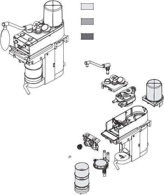
Patient path |
The parts in Figure 2-1 send exhaled gas back to the patient. They may require |
||
|
|
more frequent cleaning/sterilization than parts in Figure 2-2. Refer to your |
||
|
|
hospital’s infection control policy. |
||
|
|
|
|
Autoclave (134°C) or |
|
|
AB.23.003 |
|
wash (mild detergent pH <10.5) |
|
|
* |
If plastic, refer to cleaning/disinfection |
|
|
|
|
||
|
|
|
procedure. If metal, autoclave (134°C) |
|
|
|
|
|
|
|
|
|
|
Wipe with a damp cloth. |
AB.23.079
* 

Figure 2-1 • These parts return exhaled gas to the patient
2-2 |
1006-0939-000 |

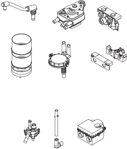
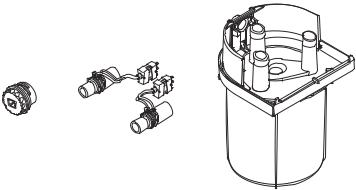
Scavenging path
AB.23.003
2 Cleaning and Sterilization
|
Autoclave (134°C) or |
2-3 |
|
||
|
|
|
|
wash (mild detergent pH <10.5) |
|
|
|
AB.23.080
Figure 2-2 • These parts do not send gas back to the patient
1006-0939-000 |
2-3 |
Aestiva
Clean and sterilize
2-4 |
The Disassembly part of this section tells you how to remove parts for |
|
cleaning. |
To wash (by hand or
machine) Patient path
AB.23.085
Scavenging path
AB.23.083
Use a mild detergent (pH <10.5). Then, rinse and dry completely. All parts except the O2 sensor, and flow sensors can be washed.
User maintenance tells you how to disassemble parts and clean inside them if necessary.
2-4 |
1006-0939-000 |

2 Cleaning and Sterilization
Autoclave
Patient path
2-5
Metal Only
AB.23.087
Upside down
AB.23.086
Scavenging path
AB.23.083
Autoclave at 134°C. Inspect the parts for deterioration. The User Maintenance section tells you how to do this.
1006-0939-000 |
2-5 |
Aestiva
Special requirements
2-6
*
* Hang the bellows upside down (extended) to dry. If not, the convolutions can stick together.
AB.23.088
•To clean the circuit O2 sensor, wipe it with a damp cloth. Do not put the sensor in liquid.
•To clean/disinfect metal/or plastic flow sensors, use the flow sensor cleaning procedure. Do not get the connectors wet.
•Disassemble the bellows before you wash it. If not, it will take a very long time to dry. Hang the bellows upside down to dry.
•Assemble the bellows before you autoclave. Autoclave the bellows upside down.
w WARNING
w CAUTION
w
w
Assemble
Do not use talc, zinc stearate, calcium carbonate, corn starch or equivalent materials to prevent tackiness. These materials can go into the patient’s lungs and airways and cause irritation or injury.
Do not put the circuit O2 sensor or flow sensor connector in liquid.
Do not autoclave the Circuit O2 sensor or the plastic flow sensors.
Do not clean the interior surfaces of the flow sensors. Use a damp cloth on external surfaces only.
The Setup section tells you how to assemble the breathing system.
Inspect all parts for deterioration. Replace them if necessary.
The Preoperative tests in Part 1 (the first half of this manual), tell you how to test the system for correct operation.
2-6 |
1006-0939-000 |
2 Cleaning and Sterilization
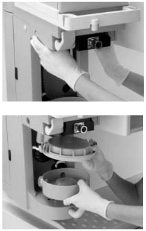
Disassemble the patient path
Step 1 |
2-7 |
|
|
Open the access panel. |
|
|
AA.96p.009 |
Step 2
Push up on the latch located under the flow sensor module.
Step 3
Remove the flow sensor module. You will feel some resistance. Continue to pull.

 AA.96p.010
AA.96p.011
Step 4
Disconnect the cable and remove the
O2 sensor.
AA.96p013, 014
1006-0939-000 |
2-7 |

Aestiva
Step 5
Completely loosen the thumbscrew on the breathing circuit module.
2-8
Step 6
Remove the module. You will feel some resistance. Continue to pull.
Step 7
Push the metal button to the first stop.
Pull out the bag arm.
Step 8
Push the metal button to the
second stop and open the top panel.
AA.96p016
AA.96p017
AA.96p018
AA.96p020
2-8 |
1006-0939-000 |

2 Cleaning and Sterilization
Step 9
Push the release button and remove the bellows assembly (pull up).
2-9
AA.96p021, 23
Step 10
Remove the main manifold.
AA.96p024
Autoclave assemblies marked 134°C. Refer to the Section “Clean and sterilize” for complete instructions. To assemble the circuit refer to the Setup section.
1006-0939-000 |
2-9 |

Aestiva
Canister disassembly
2-10 |
w CAUTION To prevent damage, pull the release handle forward. Then turn the handle |
Step 1
Pull the release forward.
AA.96p026 wZ
Step 2
Turn the release clockwise.
AA.96p028
Step 3
Pull down and out on the canisters.
AA.96p029
2-10 |
1006-0939-000 |
2 Cleaning and Sterilization
Step 4
Push in the buttons on each side of the top dish.
2-11
AA.96p053
Step 5
Lift up the drain dish.
Remove the top dish and drain dish.
AA.96p054
Continue with the next section or go to "Clean and sterilize". To assemble, refer to the Setup section.
1006-0939-000 |
2-11 |

Aestiva
Disassemble the scavenging path
These parts send exhaled gas to the disposal system, not the patient.
2-12
Exhalation valve
Complete the basic disassembly procedure.
Push in the latches and pull out the exhalation valve.
AB.23.089
Scavenging reservoir
Loosen the knob and remove the rear cover.
Pull the reservoir up and to the rear.
Twist and pull down to remove the tube.
AB.23.090
2-12 |
1006-0939-000 |
2 Cleaning and Sterilization
How to clean and disinfect the flow sensors
wCAUTION Do not autoclave plastic flow sensors.
2-13
wDo not use high-pressure gas, or brushes to clean the flow sensors.
wDo not use cleaning solvents that are not approved for use with Polycarbonates (e.g. CIDEX Plus).
CIDEX sterilization Both Datex-Ohmeda and the manufacturer of CIDEX (Johnson & Johnson) have tested this procedure.
•CIDEX must be 14 day mixture, with activator vial REF REORDER # 2245
•One liter of this solution cleans four (4) flow sensors
Procedure (Figure 2-3) 1. Remove the flow sensor module from the absorber. Refer to “Disassemble the patient path” in this section.
2.Remove the flow sensors from the module.
•Push in the latch.
•Pull off the cover.
•Remove the flow sensors.
3.Submerge the flow sensor and tubes in activated CIDEX solution. Keep the connector dry.
4.Keep the solution in the tubes for the sterilization period.
5.Submerge the flow sensor and tubes in distilled water. Again, do not get the connector wet.
6.Rinse as indicated in CIDEX instructions.
7.Do steps 5 and 6 again to remove all CIDEX.
8.COMPLETELY dry the flow sensor and the tubes before you use the sensor.
Use a dry syringe, or connect vacuum or pressure to remove all liquid from the sensor (sensor, tubes, and connector):
•Minimum time: 1 min
•Maximum vacuum: 30 in Hg
•Maximum flow: 10 L/min flow
•Maximum pressure: 345 kPa (50 psi).
1006-0939-000 |
2-13 |

Aestiva
2-14
Step 2
Steps 3 and 4
Steps 5, 6 and 7
Step 8
Dry for > 1 min with these precautions:
• Maximum vacuum 30 in Hg
• Maximum flow 10 L/min
• Maximum pressure 345 kPa (50 psi)
Figure 2-3 • Steps 2-8
2-14 |
1006-0939-000 |

2 Cleaning and Sterilization
How to clean and sterilize the optional CO2 bypass assembly
|
These instructions assume that the system has the optional CO2 bypass |
|
|
feature installed. |
2-15 |
|
|
|
|
|
|
Step 1 |
|
|
Remove the absorber canisters. (Also described in “Canister disassembly” in this section.) |
|
|
a. Pull the canister release handle forward. |
|
|
w CAUTION |
To prevent damage, pull the canister release handle forward before turning the |
|
|
handle. |
|
b.Turn the release handle clockwise.
c.Lift out the canisters.
Note: The canisters should drop under their own weight when released. If they do not, clean and lubricate the pins in the drain dish and sockets in the base.
Step 2
Release the CO2 bypass assembly by pushing both buttons (one on each side of the assembly).
Step 3
Pull down on the CO2 bypass assembly
(a)to remove it and lift the drain dish
(b)up.
a
b
1006-0939-000 |
2-15 |

Aestiva
|
Step 4 |
|
Clean and sterilize the bypass |
2-16 |
assembly: |
a. Immerse the assembly into a solution of mild detergent and water.
b. Agitate the assembly in the solution while repeatedly actuating and releasing the plate.
c.Rinse the assembly by immersing it in clean water and
agitating it again with the plate |
a |
|
actuated and released. |
||
|
d.Autoclave the assembly at 134°C.
e.Cool about 40 minutes at room temperature.
Note: Optionally, the bypass assembly can be divided into two smaller sections for easier cleaning by releasing the top clamp (a) and pulling the hose from the assembly. When reassembling, reattach the hose to the bottom part of the assembly. Secure the hose with the clamp and pinch the clamp one notch past finger-tight with pliers.
Step 5
Reinstall the bypass assembly:
a.Reinstall the drain dish.
b.Insert the bypass assembly.
c.Push back and adjust to locate the access holes for the top ports.
d.Push the buttons on each side of the assembly and push the assembly up; both buttons should snap into place.
e.Pull down on the assembly to make sure it is locked into place.
d
c
b
a
2-16 |
1006-0939-000 |
 Loading...