

Page 1

6-ChannelDigitalProportionalR/CSystem
TM
TM
INSTRUCTION MANUAL
1M23N30302
Page 2

Technical updates and additional programming examples available at: http://www.futaba-rc.com/faq
Entire Contents © 2015
Page 3
TABLE OF CONTENTS
Introduction ............................................6
●Support and Service ..................................6
●Application, Export, and Modication ....7
●Denitions of Symbols ...............................9
●Precautions (do not operate without
reading) .......................................................9
Before use ..............................................14
●Features ...................................................14
●Contents and technical specications ....15
●System compatibilty ................................15
●Accessories ................................................16
●Transmitter controls ................................17
●Battery ......................................................19
●How to turn transmitter power ON/OFF .23
●Adjusting display contrast .....................23
●Transmitter displays & buttons .............24
●Keys lock ..................................................25
●Stick control ............................................25
Stick control : Airplane example ................. 26
Stick control : Helicopter example .............. 27
Stick control : Multicopter example ............ 28
INTRODUCTION
BEFORE USE
COMMON
AIRPLANE
HELICOPTER
●Digital trims ............................................29
●Connector/Plug ........................................30
●Switch assignment table ..........................31
●Receiver and servo connections ..............32
●Adjusting the length of the control sticks ..35
●Stick lever tension adjustment................35
●Warning & error displays .......................36
●Link procedure ........................................37
●Receiver nomenclature ............................38
●R3006SB CH mode ..................................39
●Receiver's antenna installation ...............40
●Mounting the servo ..................................41
●Mounting the power switch ....................41
GLIDER
MULTICOPTER
TX SETTING
3
Page 4

●Range check the radio .............................42
●S.BUS/S.BUS2 Installation .....................43
●S.BUS Wiring example ............................44
●S.BUS2 System .........................................45
●S.BUS/S.BUS2 Device setting .................46
●Telemetry System .....................................47
Common function.................................48
●Model select ..............................................50
Model select .................................................... 51
RX type ............................................................ 51
Link ................................................................. 51
Date reset ......................................................... 52
Model copy ...................................................... 52
●Model type ................................................53
Model type ...................................................... 54
Wing type ........................................................ 54
Tail type ........................................................... 54
Swash type ...................................................... 54
Speech volume ................................................ 67
Stick position alarm ....................................... 67
●Program mixing .......................................68
●AUX channel ............................................71
●Servo monitor/Servo test ....................72
●Telemetry ..................................................73
Telemetry:Rx-batt .......................................... 73
Telemetry:Ext-volt ......................................... 77
Optional telemetry sensors ............................ 81
Telemetry:temp............................................... 82
Telemetry:rpm ................................................ 83
Telemetry:altitude .......................................... 84
Telemetry:vario .............................................. 85
●Sensor ........................................................86
Sensor:register ................................................ 87
●S.BUS servo link ......................................88
●Model transfer..........................................91
●Timer .........................................................92
●Trainer ......................................................94
●Model name ..............................................55
Model name .................................................... 55
User name ....................................................... 56
●Fail safe .....................................................57
●End point ..................................................59
●Trim...........................................................60
●Sub trim ....................................................61
●Servo reverse ............................................62
●Parameter .................................................63
LCD contrast .................................................. 64
Back light ........................................................ 65
Light time ........................................................ 65
Light adjustment ............................................ 65
Battery alarm voltage ................................... 65
Battery alarm voltage vibration ................... 65
Buzzer tone ..................................................... 65
Home display .................................................. 66
Telemetry mode .............................................. 66
Telemetry unit ................................................. 66
Speech language ............................................. 66
Airplane function .................................96
●Throttle cut ...............................................98
●Dual rate/EXPO ................................100
●Throttle curve ........................................102
●Idle down ................................................103
●Gyro sensor ............................................104
●Aileron Differential ................................105
●V-Tail .......................................................106
●Camber ...................................................107
●Air brake ................................................108
●Elevator→Flap mixing .......................... 110
●Flap→Elevator mixing .......................... 111
●Elevon .....................................................112
Helicopter function ............................113
●Condition ................................................ 115
●Throttle cut .............................................116
4
Page 5

●Dual rate /EXPO ................................ 118
●Stick-mode ..............................................159
●Trim offset ..............................................120
●Delay .......................................................121
●Gyro sensor ............................................122
●Swash AFR .............................................123
●Swash mixing .........................................124
●Throttle curve ........................................126
●Pitch curve ..............................................128
●Revolution mixing (PIT to RUD) .........130
●Throttle hold ..........................................132
●Hovering throttle ...................................133
●Hovering pitch .......................................134
Glider function ...................................135
●Condition ................................................137
●Dual rate /EXPO ................................138
●Motor switch ..........................................140
●Gyro sensor ............................................141
●Stick-adjustment ....................................159
●Throttle stick reverse .............................160
●Language ................................................160
●Aileron Differential ................................142
●V-tail ........................................................143
●Buttery mixing .....................................144
●Trim mix .................................................145
●Elevator→Camber mixing ....................146
●Camber mixing ......................................148
●Aileron→Camber mixing ......................149
Multicopter function ..........................150
●Flight mode .............................................152
●Center alarm ..........................................153
●Dual rate/EXPO ................................154
●Throttle curve ........................................156
●Throttle delay .........................................157
●Gyro sensor ............................................158
TX setting ............................................159
5
Page 6

INTRODUCTION
Thank you for purchasing a Futaba
system. This system is extremely versatile and may be used by beginners and pros alike. In order
for you to make the best use of your system and to y safely, please read this manual carefully.
If you have any difficulties while using your system, please consult the manual, our online
Frequently Asked Questions (on the web pages referenced below), your hobby dealer, or the
Futaba Service Center.
®
T-FHSS Air-2.4GHz 6K series digital proportional R/C
Introduction
Due to unforeseen changes in production procedures, the information contained in this manual is
subject to change without notice.
Support and Service: It is recommended to have your Futaba equipment serviced annually during
your hobby’s “off season” to ensure safe operation.
IN NORTH AMERICA
Please feel free to contact the Futaba Service Center for assistance in operation, use and
programming. Please be sure to regularly visit the 6K Frequently Asked Questions web site
at www.futaba-rc.com/faq/. This page includes extensive programming, use, set up and safety
information on the 6K radio system and is updated regularly. Any technical updates and US
manual corrections will be available on this web page. If you do not nd the answers to your
questions there, please see the end of our F.A.Q. area for information on contacting us via email
for the most rapid and convenient response.
Don’t have Internet access? Internet access is available at no charge at most public libraries,
schools, and other public resources. We nd internet support to be a fabulous reference for many
modelers as items can be printed and saved for future reference, and can be accessed at any hour
of the day, night, weekend or holiday. If you do not wish to access the internet for information,
however, don’t worry. Our support teams are available Monday through Friday 8-5 Central time
to assist you.
FOR SERVICE ONLY:
Futaba Service Center
3002 N. Apollo Drive, Suite 1
Champaign, IL 61822
Phone: 217-398-0007
www.futaba-rc.com/service.html
Email: futabaservice@hobbico.com
OUTSIDE NORTH AMERICA
Please contact your Futaba importer in your region of the world to assist you with any questions,
problems or service needs.
Please recognize that all information in this manual, and all support availability, is based upon
the systems sold in North America only. Products purchased elsewhere may vary. Always contact
your region’s support center for assistance.
(PROGRAMMING AND USER
Please start here for answers to most questions:
FOR SUPPORT :
QUESTIONS)
www.futaba-rc.com/faq/
Fax: 217-398-7721
Phone: 217-398-8970 option 2
6
Page 7

Application, Export, and Modication
1. This product may be used for model airplane or surface (boat, car, robot) use. It is not intended
for use in any application other than the control of models for hobby and recreational purposes.
The product is subject to regulations of the Ministry of Radio/Telecommunications and is
restricted under Japanese law to such purposes.
2. Exportation precautions:
(a) When this product is exported from the country of manufacture, its use is to be approved by
the laws governing the country of destination which govern devices that emit radio frequencies. If
this product is then re-exported to other countries, it may be subject to restrictions on such export.
Prior approval of the appropriate government authorities may be required. If you have purchased
this product from an exporter outside your country, and not the authorized Futaba distributor in
your country, please contact the seller immediately to determine if such export regulations have
been met.
(b) Use of this product with other than models may be restricted by Export and Trade Control
Regulations, and an application for export approval must be submitted. This equipment must not
be utilized to operate equipment other than radio controlled models.
3. Modication, adjustment, and replacement of parts: Futaba is not responsible for unauthorized
modication, adjustment, and replacement of parts on this product. Any such changes may void
the warranty.
Compliance Information Statement (for U.S.A.)
This device, trade name Futaba Corporation, complies with part 15 of the FCC Rules. Operation
is subject to the following two conditions:
(1) This device may not cause harmful interference, and
(2) This device must accept any interference received, including interference that may cause
undesired operation.
(3) This module meets the requirements for a mobile device that may be used at separation
distances of more than 20cm from human body.
To meet the RF exposure requirements of the FCC this device shall not be co-located with another
transmitting device.
The responsible party of this device compliance is:
Futaba Service Center
3002 N Apollo Drive Suite 1, Champaign, IL 61822 U.S.A.
TEL (217)398-8970 or E-mail: support@hobbico.com (Support)
TEL (217)398-0007 or E-mail: futabaservice@hobbico.com (Service)
Introduction
The RBRC. SEAL on the nickel-cadmium battery contained in Futaba products
indicates that Futaba Corporation is voluntarily participating in an industry-wide
program to collect and recycle these batteries at the end of their useful lives, when
taken out of service within the United States. The RBRC. program provides a
convenient alternative to placing used nickel-cadmium batteries into the trash or
municipal waste system, which is illegal in some areas.
(for USA)
You may contact your local recycling center for information on where to return the spent battery.
Please call 1-800-8BATTERY for information on NiCd battery recycling in your area. Futaba
Corporation involvement in this program is part of its commitment to protecting our environment
and conserving natural resources.
*RBRC is a trademark of the Rechargeable Battery Recycling Corporation.
7
Page 8

Federal Communications Commission Interference Statement (for U.S.A.)
This equipment has been tested and found to comply with the limits for a Class B digital device,
pursuant to Part 15 of the FCC Rules. These limits are designed to provide reasonable protection
against harmful interference in a residential installation.
This equipment generates, uses and can radiate radio frequency energy and, if not installed
and used in accordance with the instructions, may cause harmful interference to radio
communications. However, there is no guarantee that interference will not occur in a particular
installation. If this equipment does cause harmful interference to radio or television reception,
Introduction
which can be determined by turning the equipment off and on, the user is encouraged to try to
correct the interference by one or more of the following measures:
--Reorient or relocate the receiving antenna.
--Increase the separation between the equipment and receiver.
--Consult the dealer or your Futaba Serivce center for help.
CAUTION:
To assure continued FCC compliance:
Any changes or modications not expressly approved by the grantee of this device could void the
user's authority to operate the equipment.
Exposure to Radio Frequency Radiation
To comply with FCC RF exposure compliance requirements, a separation distance of at least
20cm must be maintained between the antenna of this device and all persons.
This device must not be co-located or operating in conjunction with any other antenna or
transmitter.
Where to Fly
We recommend that you y at a recognized model airplane ying eld. You can nd model
clubs and elds by asking your nearest hobby dealer, or in the US by contacting the Academy
of Model Aeronautics.
You can also contact the national Academy of Model Aeronautics (AMA), which has more
than 2,500 chartered clubs across the country. Through any one of them, instructor training
programs and insured newcomer training are available. Contact the AMA at the address or toll-
free phone number below.
Academy of Model Aeronautics
5161 East Memorial Drive
Muncie, IN 47302
Tele. (800) 435-9262
Fax (765) 289-4248
or via the Internet at http:\\www.
modelaircraft.org
Always pay particular attention to the ying eld’s rules, as well as the presence and
location of spectators, the wind direction, and any obstacles on the eld. Be very careful
ying in areas near power lines, tall buildings, or communication facilities as there may be
radio interference in their vicinity.
8
Page 9
Precautions
Application, Export, and Modification Precautions.
1. This product is only designed for use with radio control models. Use of the product described in this instruction
manual is limited to radio control models.
2. Export precautions:
a) When this product is exported, it cannot be used where prohibited by the laws governing radio waves of the
destination country.
b) Use of this product with other than models may be restricted by Export and Trade Control Regulations.
3. Modification, adjustment, and parts replacement
Futaba is not responsible for unauthorized modification, adjustment, or replacement of parts on this product.
■ No part of this manual may be reproduced in any form without prior permission.
■ The contents of this manual are subject to change without prior notice.
■ The contents of this manual should be complete, but if there are any unclear or missing parts please contact a
Futaba Service Center.
■ Futaba is not responsible for the use of this product by the customer.
■ Company and product names in this manual are trademarks or registered trademarks of the respective company.
For safe use
Please observe the following precautions to ensure safe use of this product at all times.
Meaning of Special Markings:
The parts of this manual indicated by the following marks require special attention from the standpoint of safety.
Introduction
DANGER - Procedures which may lead to dangerous conditions and cause death/serious injury if not carried out
WARNING - Procedures which may lead to a dangerous condition or cause death or serious injury to the user if not
CAUTION - Procedures where the possibility of serious injury to the user is small, but there is a danger of injury, or
WARNING:
properly.
carried out properly, or procedures where the probability of supercial injury or physical damage is high.
physical damage, if not carried out properly.
= Prohibited
Always keep electrical components away from small children.
= Mandatory
Flying Precautions
WARNING
Never grasp the transmitter built-in antenna
part while ying.
■ The transmitter output may drop drastically.
Always make sure that all transmitter stick
movements operate all servos properly in the
model prior to flight. Also, make sure that all
switches, etc. function properly as well. If there
are any diculties, do not use the system until all
inputs are functioning properly.
Never y in the range check mode.
■ In the dedicated range test range check mode, the
transmitter output range is reduced and may cause a
crash.
While operating, never touch the transmitter
with, or bring the transmitter near, another
transmitter, a cellphone, or other wireless devices.
■ Doing so may cause erroneous operation.
9
Page 10
Never fly on a rainy day, when the wind is
strong, and at night.
■ Water could lead to failure or improper functionality
and poor control of the aircraft which could lead to a
crash.
Never turn the power switch on and o during
ight or while the engine or motor is running.
■ Operation will become impossible and the aircraft will
Introduction
crash. Even if the power switch is turned on, operation
will not begin until transmitter and receiver internal
processing is complete.
Do not start the engine or motor while wearing
the neck strap.
■ The neck strap may become entangled with the
rotating propeller, rotor, etc. and cause a serious injury.
Do not y when you are physically impaired as
it could pose a safety hazard to yourself or others.
Do not y at the following places:
■ Near another radio control ying eld.
■ Near or above people.
■ Near homes, schools, hospitals or other places where
people congregate.
■ Near high voltage lines, high structures, or
communication facilities.
When setting the transmitter on the ground
during ight preparations, do not stand it upright.
■ The transmitter may tip over, the sticks may move and
the propeller or rotor may rotate unexpectedly and cause
injury.
Do not touch the engine, motor, or FET amp
during and immediately after use.
■ These items may become hot during use.
For safety, y so that the aircraft is visible at all
times.
■ Flying behind buildings or other large structures
will not only cause you to lose sight of the aircraft, but
also degrade the RF link performance and cause loss of
control.
From the standpoint of safety, always set the
fail safe function.
■ In particular, normally set the throttle channel to idle.
For a helicopter, set the throttle channel to maintain a
hover.
When flying, always return the transmitter
setup screen to the Home screen.
■ Erroneous input during ight is extremely dangerous.
Always check the remaining capacity of the
transmitter and receiver batteries before each
ying session prior to ight.
■ Low battery capacity will cause loss of control and a
crash.
Always check operation of each control surface
and perform a range test before each flying
session. Also, when using the trainer function,
check the operation of both the teacher and
student transmitter.
■ Even one transmitter setting or aircraft abnormality
cause a crash.
Before turning on the transmitter:
1. Always move the transmitter throttle stick position to
the minimum (idle) position.
2. Turn on the transmitter rst and then the receiver.
When turning off the transmitter's power
switch. After the engine or motor has stopped
(state in which it will not rotate again):
1. Turn o the receiver power switch.
2. Then turn o the transmitter power switch.
■ If the power switch is turned on/off in the opposite
order, the propeller may rotate unexpectedly and cause a
serious injury.
■ Also always observe the above order when setting the
fail safe function.
■ Maximum low throttle: Direction in which the engine
or motor runs at the slowest speed or stops.
When adjusting the transmitter, stop the
engine except when necessary. In the case of
a motor, disconnect the wiring and to allow it
to continue operation. When doing so, please
exercise extreme caution. Ensure that the aircraft
is secured and that it will not come into contact
with anything or anyone. Ensure that the motor
will not rotate prior to making any adjustments.
■ Unexpected high speed rotation of the engine may
cause a serious injury.
10
Page 11
Battery and Charger Handling Precautions
DANGER
Do not recharge a battery that is damaged,
deteriorated, leaking electrolyte, or wet.
Do not use the charger in applications other
than as intended.
Do not allow the charger or battery to become
wet.
■ Do not use the charger, when it or your hands, are wet.
Do not use the charger in humid places.
Do not short circuit the battery.
Do not solder or repair, deform, modify, or
disassemble the battery and/or battery charger.
Do not drop the battery into a fire or bring it
near a re.
Do not charge and store the battery in direct
sunlight or other hot places.
Do not charge the battery if it is covered with
any object as it may become very hot.
Do not use the battery in a combustible
environment.
■ The gas ignite and cause an explosion or re.
Always charge the battery before each flying
session.
■ If the battery goes dead during ight, the aircraft will
crash.
Charge the nickel-hydride battery with the
dedicated charger supplied with the set.
■ Charging the battery past the specified value may
cause a re, combustion, rupture, or liquid leakage. When
quick charging, do not charge the battery above 1C.
■ Do not charge the battery while riding in a vehicle.
Vibration will prevent normal charging.
When using the optional Li-Fe battery,
disconnect the battery from the transmitter and
charge it with the special LBC-4E5 Li-Fe Battery
Charger sold separately.
When using the optional Li-Fe battery, do
not connect the charger to the balance charge
connector and the power connector at the same
time.
■ Doing so cause a re, combustion, generation of heat,
rupture, or liquid leakage.
Insert the power cord plug firmly into the
receptacle up to its base.
Always use the charger with the specified
power supply voltage.
■ Use the special charger by connecting it to a proper
power outlet.
If the battery should get in your eyes, do not
rub your eyes, but immediately wash them with
tap water or other clean water and get treated by
a doctor.
■ The liquid can cause blindness.
Introduction
WARNING
Do not touch the charger and battery for any
length of time during charging.
■ Doing so may result burns.
Do not use a charger or battery that has been
damaged.
Do not touch any of the internal components
of the charger.
■ Doing so may cause electric shock or a burn.
If any abnormalities such as smoke or
discoloration are noted with either the charger
or the battery, remove the battery from the
transmitter or charger and disconnect the power
cord plug and do not use the charger.
■ Continued use may cause re, combustion, generation
of heat, or rupture.
Do not subject the batteries to impact.
■ Doing so may cause fire, combustion, generation of
heat, rupture, or liquid leakage.
Do not repeatedly charge a nickel-hydrogen
battery in the shallow discharge state.
■ The battery memory effect will substantially shorten
the battery life even if it is recharged.
Use and store the battery and battery charger
in a secure location away from children.
■ Doing so may cause electric shock or injury.
If the battery leaks liquid or generates an
abnormal odor, immediately move it to a safe
place for disposal.
■ Not doing so may cause combustion.
If the battery liquid gets on your skin or
clothing, immediately flush the area with tap
water or other clean water.
■ Consult a doctor. The liquid can cause skin damage.
After the specied charging time has elapsed,
end charging and disconnect the charger from the
receptacle.
When recycling or disposing of the battery,
isolate the terminals by covering them with
cellophane tape.
■ Short circuit of the terminals may cause combustion,
generation of heat or rupture.
11
Page 12
CAUTION
Do not use the nickel-hydride battery with
devices other than the corresponding transmitter.
Do not place heavy objects on top of the
battery or charger. Also, do not place the battery
or charger in any location where it fall.
■ Doing so may cause damage or injury.
Introduction
Do not store or use the battery and charger
where it is dusty or humid.
■ Insert the power cord plug into the receptacle only
after eliminating the dust.
After the transmitter has been used for a long
time, the battery may become hot. Immediately
remove from the transmitter.
■ Not doing so may cause a burn.
Storage and Disposal Precautions
WARNING
Keep wireless equipment, batteries, aircraft,
etc. away from children.
CAUTION
Do not store wireless devices in the following
places:
・ Where it is extremely hot (40℃ [104F] or higher)
or cold (-10℃ [14F] or lower)
・ Where the equipment will be exposed to direct
sunlight
・ Where the humidity is high
・ Where vibration is prevalent
・ Where it is very dusty
・ Where the device may be exposed to steam and
heat
Do not charge the battery in extreme
temperatures.
■ Doing so will degrade the battery performance. An
ambient temperature of 10℃ to 30℃ (50F to 86F) is ideal
for charging.
Unplug the charger when not in use.
Do not bend or pull the cord unreasonably and
do not place heavy objects on the cord.
■ The power cord may be damaged and cause
combustion, generation of heat, or electric shock.
When the device will not be used for a long
time, remove the battery from the transmitter
and aircraft and store them in a dry place where
the temperature is between 0 and 30℃ [32F and
86F].
■ Left standing 'as is' may will cause battery deterioration,
liquid leakage, etc.
Other Precautions
CAUTION
Do not directly expose plastic parts to fuel, oil,
exhaust gas, etc.
■ If left in such an environment, the plastic may be
attacked and damaged.
■ Since the metal parts of the case may corrode, always
keep them clean.
Join the Academy of Model Aeronautics.
■ The Academy of Model Aeronautics (AMA) provides
guidelines and liability protection should the need arise.
Always use genuine Futaba products such as
transmitter, receiver, servo, FET amplier, battery,
etc.
12
■ Futaba is not responsible for damage sustained by
combination with other than Futaba Genuine Parts. Use
the parts specied in the instruction manual and catalog.
Page 13

Introduction
13
Page 14

BEFORE USE
FEATURES
●T-FHSS Air-2.4G multi-function 6-channel transmitter
The Futaba 2.4GHz T-FHSS Air system is employed.
●Telemetry system
A T-FHSS Air bidirectional communication system is used. The voltage of the battery mounted in the
fuselage can be displayed at the transmitter during ight. Altitude, temperature and R.P.M data can be
displayed at the transmitter by installing various optional telemetry sensors in the fuselage.
●Speech function
Telemetry data can be listened to by plugging commercial earphones into the transmitter.
●Built-in antenna
Before use
Antenna built into the transmitter provides a simple appearance and improves handling ease.
●S.BUS/S.BUS2 servo setting function
S.BUS/S.BUS2 servo channel and various functions can be set by connecting the servo to the
transmitter.
●Power-saving type transmitter
Four AA's alkaline batteries can be used. The optional HT5F1800B (NiMH 6.0V, 1800mA) or
FT2F2100BV2 (lithium-ferrite 6.6V, 2100mA) battery can also be used.
●Vibration
A function that noties the operator of various alarms by vibrating the transmitter can be selected.
●Unique model memory system
The transmitter body contains a 30 model memory.
●Mixing type selection
Fixed wing, helicopter, and glider mixing type can be selected to match the fuselage. In addition, 6
swash plate types can also be selected for helicopters. Multi-copter selection is also possible.
●Digital trim
Rapid trimming during ight is possible. The sound changes at the center of trim. The step size can be
arbitrarily changed. The trim position is displayed on the LCD.
●Lever head length adjustment
The lever head length can be adjusted. Lever head shape that reduces slip during operation has been
adopted.
●Switch/VR position change and AUX channel function change
Mixing and other switches and VR can be selected. Since the function of the AUX channels (5ch
6ch) can also be changed, original mixing, in addition to existing mixing, can be created by using the
programmable mixing function.
●Model data transfer function
Model data can be wirelessly transferred between 6K.
R3006SB receiver
●T-FHSS Air system S.BUS compatible
S.BUS output and conventional channel output are provided. S.BUS and conventional system sharing is
possible.
,
●Battery fail safe function
14
Page 15
CONTENTS AND TECHNICAL SPECIFICATIONS
(Specications and ratings are subject to change without notice.)
Your 6K includes the following components:
• T6K transmitter for airplanes or helicopters
• R3006SB Receiver
• Switch harness
*The set contents depend on the type of set.
Transmitter T6K
(2-stick, 6-channel, T-FHSS Air-2.4G system)
Transmitting frequency: 2.4GHz band
System: T-FHSS Air, S-FHSS, switchable
Power supply: 6.0V Dry battery
Receiver R3006SB
(T-FHSS Air-2.4G system, dual antenna diversity, S.BUS, S.BUS2 system)
Power requirement: 4.8V~7.4V battery or regulated output from ESC, etc. (*1)
Size: 1.7 x 0.98 x 0.35 in. (43.1 x 25.0 x 8.8 mm)
Weight: 0.3 oz. (8.5g)
Battery F/S Voltage: It sets up with a transmitter
(*1) When using ESC's make sure that the regulated output capacity meets your usage application.
Before use
SYSTEM COMPATIBILITY
The 6K is a
system cannot be used with S-FHSS.) The usable receivers are shown below.
2.4GHz T-FHSS Air system
Communications System
T-FHSS Air
(Default)
S-FHSS
(Change is possible)
NOTE:
*The Futaba
it with a
be used with an
cannot be used.
*The
T-FHSS Air system
R304SB, R304SB-E
T-FHSS Air
T-FHSS Air
S-FHSS
system cannot be used with Futaba
system transmitter and receiver. The
receiver by switching to
and
or
T-FHSS
. The transmitter can also be switched to
R3006SB, R3008SB
*R304SB, R304SB-E, T-FHSS surface system
receivers do not operate.
R2008SB
R2006GS
R2106GF
S-FHSS/FASST/FASSTest
T6K
S-FHSS
T-FHSS
surface system are different. The
surface system receivers.
. However, in this case the telemetry system
is a
. (However, the telemetry
S-FHSS
Usable Receivers
T-FHSS Air system
cannot be used with the
T6K
systems. Use
, but can also
15
Page 16

The following additional accessories are available from your dealer. Refer to a Futaba catalog for
more information:
• HT5F1800B Transmitter battery pack - the (1800mAh) transmitter NiMH battery pack may be easily
exchanged with a fresh one to provide enough capacity for extended ying sessions.
• FT2F2100BV2 Transmitter LiFe battery pack can also be used. However, charge with the charger only for
LiFe.
• Trainer cord - the optional training cord may be used to help a beginning pilot learn to fly easily by
placing the instructor on a separate transmitter. Note that the T6K transmitter may be connected to another
T6K system, as well as to any other models of Futaba transmitters. The T6K transmitter uses one of the
three cord plug types according to the transmitter connected. (Refer to the description at the TRAINER
Before use
function instructions). The part number of this cord is: FUTM4405.
• Servos - there are various kinds of servos. Please choose the Futaba servos best suited for the model and
purpose you are using them for. If you utilize a S.BUS system, you should choose a S.BUS servo.
• Telemetry sensor - please purchase an optional sensor, in order to utilize bidirectional communication
system and to acquire the information from a model high up in the sky.
Temperature sensor : SBS-01T/TE] [Altitude sensor : SBS-01A] [RPM sensor magnet type : SBS-
[
01RM][RPM sensor optical type : SBS-01RO] [RPM sensor brushless motor type : SBS-01RB]
• Neckstrap - a neckstrap can be connected to your T6K system to make it easier to handle and improve
your ying precision since your hands won’t need to support the transmitter’s weight.
• Y-harnesses, servo extensions, hub,etc - Genuine Futaba extensions and Y-harnesses, including a heavyduty version with heavier wire, are available to aid in your larger model and other installations.
• Gyros - a variety of genuine Futaba gyros is available for your aircraft or helicopter needs.
• Receivers - various models of Futaba receivers may be purchased for use in other models. (Receivers for
T-FHSS Air, S-FHSS types are available.)
16
Page 17
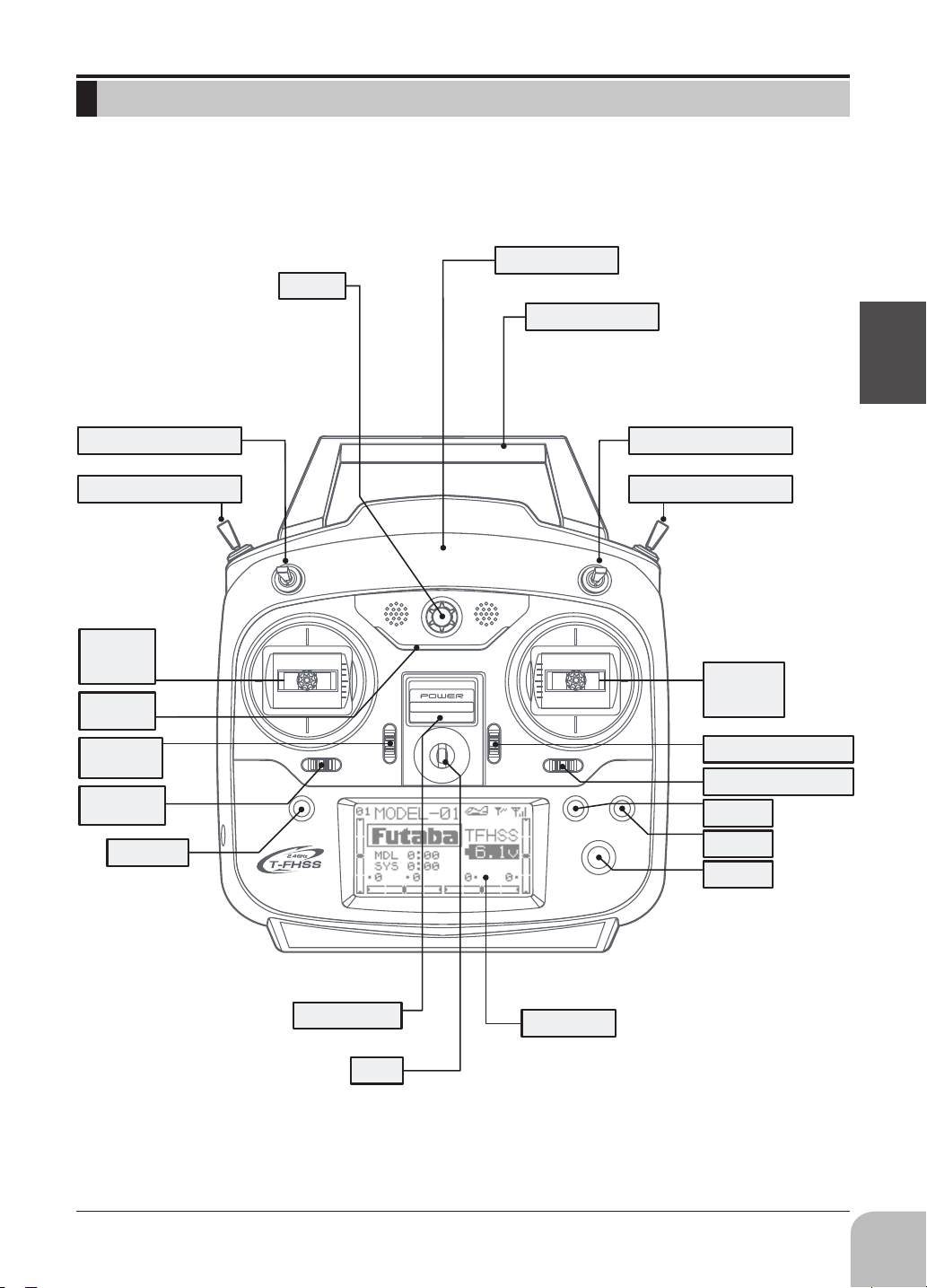
TRANSMITTER CONTROLS - T6K
Built-in Antenna
Volume
Carrying Handle
Before use
3 Position Switch (A)
3 Position Switch (C)
Rudder
/Throttle
Stick
Power
LED
Throttle
Trim Lever
Rudder
Trim Lever
END Key
3 Position Switch (B)
2 Position Switch (D)
Elevator
/Aileron
Stick
Elevator Trim Lever
Aileron Trim Lever
+ Key
- Key
Jog Key
Power Switch
(Up position: ON)
Hook
(for optional neckstrap)
LCD Panel
17
Page 18
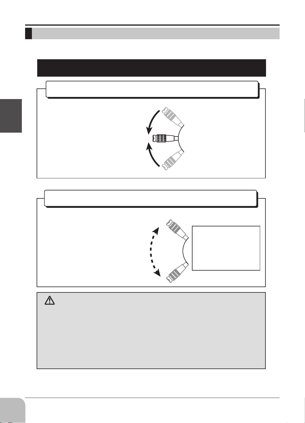
Multicopter/Robot specication
Throttle stick warning
Before use
Self neutral type
A throttle stick returns
neutrally by a spring.
Ratchet type(General transmitter)
A throttle stick doesn't return
neutrally.
(Multicopter/Robot specication)
Throttle stick:
Motor or engine
power is controlled.
18
WARNING
You cannot use the throttle stick of self-neutral type for RC
airplane, RC helicopter, and certain multi-copter.
It's very dangerous if Engine / Motor becomes middle-speed
by self-return.
It's necessary to change the stick to the ratchet type if using it for
RC airplane and RC helicopter.
Page 19
INSTALLATION AND REMOVAL OF THE T6K BATTERY
The T6K transmitter is designed to work with either four (4) AA alkaline dry cell batteries, or
HT5F1800B battery pack, both available separately. The transmitter batteries used are a matter of personal
preference. AA Alkaline batteries are available at any local hobby shop, grocery store, etc. A battery pack
will need to be purchased from a hobby shop.
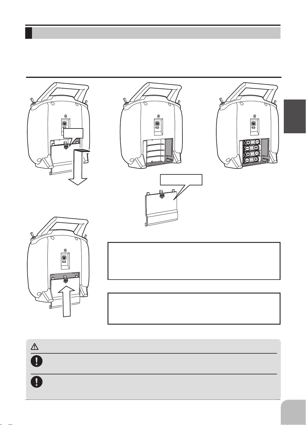
Battery Replacement Method
Push
Slide the battery cover o the
transmitter in the direction of
the arrow in the gure.
Slide the battery cover
back onto the case.
Battery Cover
Check:
Load the new AA size
batteries. Pay very close
attention to the polarity
markings and reinsert
accordingly.
Turn the power switch on the transmitter to the ON position.
Check the battery voltage display on the LCD screen. If the
voltage is low, check the batteries for insufcient contact in
the case or incorrect battery polarity.
Disposal of the Dry Cell Batteries:
The method to dispose of used dry cell batteries depends on
the area in which you reside. Dispose of the batteries in ac
cordance with the regulations for your area.
Before use
-
CAUTION
Always be sure you reinsert the batteries in the correct polarity order.
If the batteries are loaded incorrectly, the transmitter may be damaged.
When the transmitter will not be used for any short or long period of time, always remove the
batteries.
oughly. Make sure the contacts are free of corrosion.
If the batteries do happen to leak, clean the battery case and contacts thor-
19
Page 20
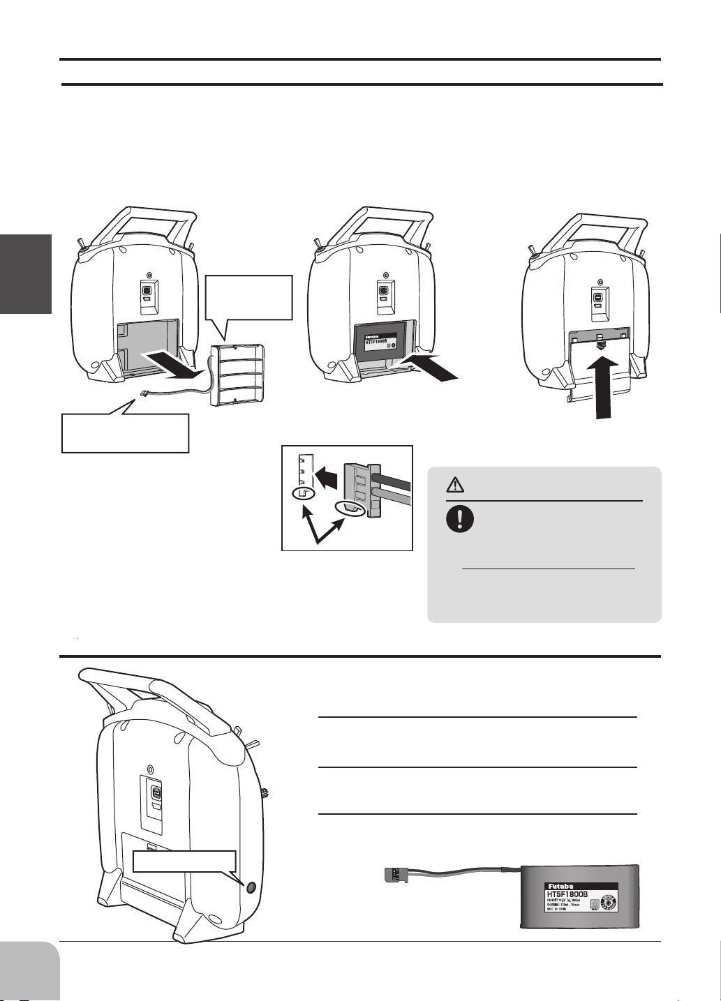
When Using The Optional Battery HT5F1800B
When using an optional rechargeable battery, replace the battery as described below.
-Always use the optional HT5F1800B rechargeable battery.
-The type of power source used must be set by system setting.
-When the transmitter will not be used for a long time, remove the battery.
Dry cell
Before use
Disconnect the
connector
Refer to the previous
description and remove the
transmitter battery cover.
After removing the dry
cell battery box from the
transmitter, disconnect the
connector.
battery BOX
Insert the connector of the
new battery and load the new
battery into the transmitter.
Connect the battery
connector.
Finish by installing the
battery cover.
CAUTION
When closing the battery
cover, be careful that the
battery cover does not pinch
the battery lead wires.
Shorting of the battery lead wires may
lead to fire and abnormal heating and
cause burns or fire disaster.
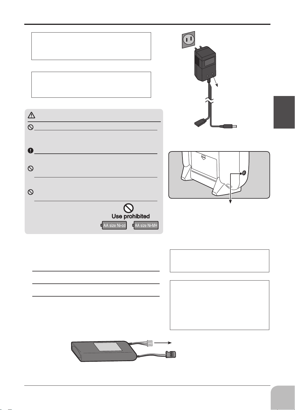
When Charging the Optional Battery HT5F1800B
(Example: When using the HT5F1800B with the special charger)
Charging jack
20
Charging a NiMH Battery
Plug the transmitter cord of the special charger into
1
the charging jack on the rear of the transmitter.
Plug the charger into an AC outlet.
2
Check that the charging LED lights.
3
NiMH battery HT5F1800B
(not included)
Page 21
The charging time when charging the HT5F1800B battery
with the optional special charger is approximately 15 hours.
However, when the battery has not been used for some time,
repeat charging 2 or 3 times to activate the battery.
Over current protection
The transmitter charging circuit is equipped with an over cur-
rent protection circuit (1.0A). If the battery is charged with a
quick charger for other than digital proportional R/C sets, it
may not be fully charged.
CAUTION
AC outlet
Charger
Transmitter
charging LED
Never try to recharge a dry cell battery.
The transmitter may be damaged or the battery electrolyte may
leak or the battery may break.
Insert the batteries in the correct polarity.
If the polarity is incorrect, the transmitter may be damaged.
When the transmitter is not in use, remove the batter-
ies.
If the battery electrolyte leaks, wipe off the case and contacts.
Do not use commercial AA size NiCd and NiMH batter-
ies.
Quick charging may cause the
battery contacts to overheat and
damage the battery holder.
Charging A LiFe Battery
(Example: When using the FT2F1700BV2/2100BV2 with the special
charger)
Remove the battery cover.
1
Disconnect the battery from the T6K.
2
Balance charging cannot be done through the
3
transmitter, you must remove the LiFe battery to do
this charge.
To receiver
Ni-Cd battery
To transmitter
charging jack
Charging jack
Cannot be used for
charge of LiFe.
Charg e the opti on al FT2F1700BV2/2100B V2
(LiFe) battery with the special charger in accor-
dance with the instruction manual supplied.
When the battery will not be used for a long time,
to prevent it from deteriorating we recommend
that it be kept in about the half capacity state instead of fully charged. Also be careful that the battery does not enter the over-discharged state due
to self-discharge.
Periodically (about every 3 months) charge the
battery.
Before use
LiFe battery is removed
from transmitter.
Balance charging connector for
LiFe battery charger.
21
Page 22
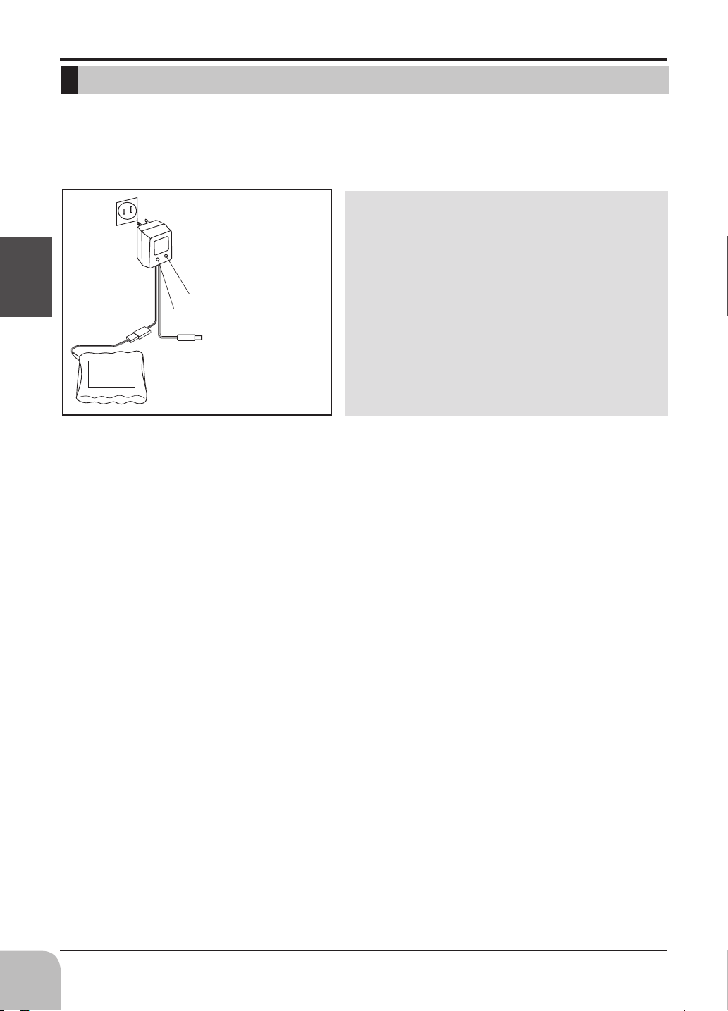
CHARGING THE BATTERIES
r
(When the rechargeable battery option is used)
Charging Your System’s Batteries
1. Connect the transmitter charging jack and batteries to the transmitter and receiver connectors
of the charger.
2. Plug the charger into a wall socket.
3. Check that the charger LED lights.
According to the description of the battery to be used
and its exclusive charger, please use it after carrying
out full charge.
We recommend charging the batteries with the
charger supplied with your system. Note that the
use of a fast charger may damage the batteries by
overheating and dramatically reduce their lifetime.
When HT5F1800B is chosen, HBC-3A (4) is
recommended.
When charging FT2F2100BV2, please make sure
to remove the battery from the system to charge it.
Charger for this battery is recommended to use LBC-
4E5.
Before use
Charger
TX: Transmitter charging indicato
RX: Receiver charging indicator
To transmitter charging jack
Receiver battery
Battery Care and Precautions
Below you will find some general rules and guidelines which should be adhered to when
charging transmitter and/or receiver battery packs. These are included to serve only as general
guidelines, and are not intended to replace or supersede the information provided by the battery
and/or charger manufacturer. For complete information, please refer to the instructions that are
included with the battery pack(s) and/or chargers that accompany the products purchased.
• Do not allow children to charge battery packs without adult supervision.
• Do not charge battery packs that have been damaged in any way. We strongly suggest frequent
inspection of the battery packs to ensure that no damage has occurred.
• Do not to allow batteries to overheat! If overheated, disconnect the battery from the charger
immediately and allow to cool.
• Do not mix cells- all cells should be of the same material, conguration, etc.
• Do not deep cycle NiMH batteries as permanent damage could result.
• Never charge batteries on a surface that may become hot, or may be impacted by the heat.
• Immediately end the charging procedure if either the batteries or charger itself become overly hot.
• NiMH cells do not exhibit the “memory effect” like NiCd cells, so little cycling is needed. Store
NiMH packs with some voltage remaining on the cells (refer to battery supplier).
• NiMH cells have a self-discharge rate of approximately 20-25% (compared to 15% for NiCd
batteries). It is important to recharge NiMH batteries immediately prior to use.
• Never connect the battery in reverse. Reverse connection will cause the battery to overheat or
will damage the inside of the charger.
• Do not add an additional charge after charging.
• Never charge with a current exceeding the nominal capacity (lC) of the rechargeable battery.
• If a battery is charged with a current exceeding 1C, the battery will overheat and deteriorate.
• Do not connect two battery packs or more to one output terminal.
• Avoid extremely cold and hot places and the direct sunlight when you charge batteries.
• It is recommended to perform charging within the 10 ~ 30°C (50-86°F) range. Otherwise, it may
cause abnormal charging and overheat.
22
Page 23
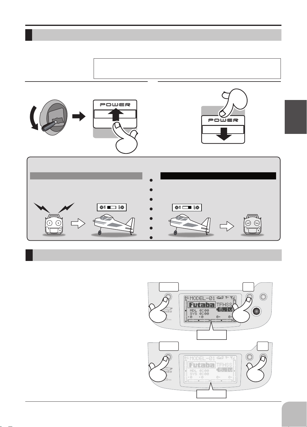
How to turn transmitter power ON/OFF
When turning on the power, the T6K transmitter will begin emitting RF automatically after it conrms
the surrounding RF conditions. The status of the transmitter is displayed by LED at the upper part of the
front of a T6K.
Throttle Stick Slow
If the power switches are turned o in the opposite order the model may unexpectedly run out of control and
cause a very dangerous situation.
Turning on the power switches
1. Turn on the transmitter power switch.
2. Turn on the receiver or speed control power switch.
*If THR stick is high, the next WARNING screen will come out. Moreover, if a power supply
is switched on while SW set by WARNING setup has been ON, it will be indicated by
WARNING.(In the case of Multicopter mode, throttle position alarm does not occur. )
Power OFFPower ON
Power Switch
Power Switch
Turning o the power switches
Always be sure the motor/engine is stopped.
1. Turn o the receiver or speed control power switch.
2. Then turn o the transmitter power switch.
Before use
ON
ON
OFF
OFF
ADJUSTING DISPLAY CONTRAST
To adjust the display contrast, from the home menu press and hold the END BUTTON.
Push the
KEY while still holding the END BUTTON:
+-
KEY to brighten
+
KEY to darken the display
-
END +
Brighten
END -
Darken
23
Page 24
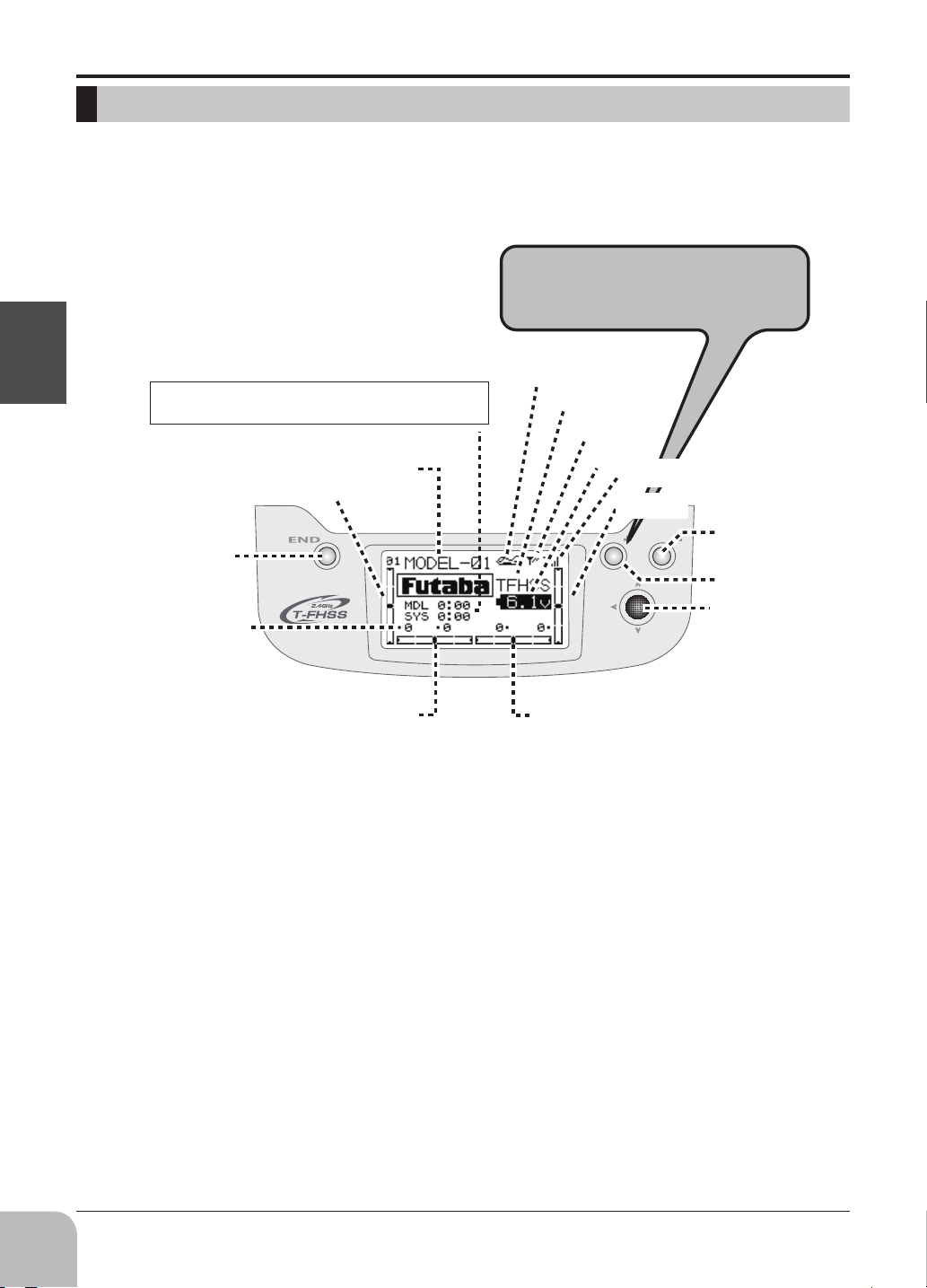
TRANSMITTER DISPLAYS & BUTTONS
When you rst turn on your transmitter, a conrmation double beep sounds, and the screen shown
below appears. Before ying, or even starting the engine, be sure that the model type and name
appearing on the display matches the model that you are about to y! If you are in the wrong model
memory, servos may be reversed, and travels and trims will be wrong, potentially leading to a crash.
Press and hold + KEY for one
second to open programming
menus.
Model type
"T-FHSS" "S-FHSS"
Output display
System
Battery
voltage
Receiving accuracy
Elevator trim
Telemetry
display
-key
+key
Jog key
Before use
Model timer display <MDL>
Shows the cumulated ON time for each model. (hours:minutes)
System timer display <SYS>
Shows the cumulated ON time. (hours:minutes)
Resetting timers:
Select the desired timer with JOG KEY. The timer display
flashes. To reset the timer, press JOG KEY.
Model number
and name
display
END
Key
Each trim
value
Throttle trim
Rudder trim
display
Aileron trim
display
Edit buttons and Start-up Screen (appears when system is rst turned on):
JOG KEY:
Control JOG KEY to scroll up/scroll down/scroll left/scroll right and select the option to edit within a
function. When the menu has multiple pages, move the JOG KEY horizontally (left or right).
Press JOG KEY to select the actual function you wish to edit from the menu.
Press JOG KEY and hold one second to confirm major decisions, such as the decision to: select
a different model from memory, copy one model memory over another, trim reset, store channel
position in FailSafe, change model type, reset entire model, condition of a helicopter setup is changed.
An on screen inquiry will ask if you are sure.
Press JOG KEY again to accept the change.
KEY:
+
Press and hold + KEY for one second to open programming menus. It is used for changing a setup,
or a numerical increase. Changing the menus pages can also be performed.
KEY:
-
It is used for change of a setup, or reduction of a number. Change of the page of a menu can also be
performed.
END KEY:
Press END KEY to return to previous screen, close functions back to menus, and close menus to start-
up screen.
24
Page 25
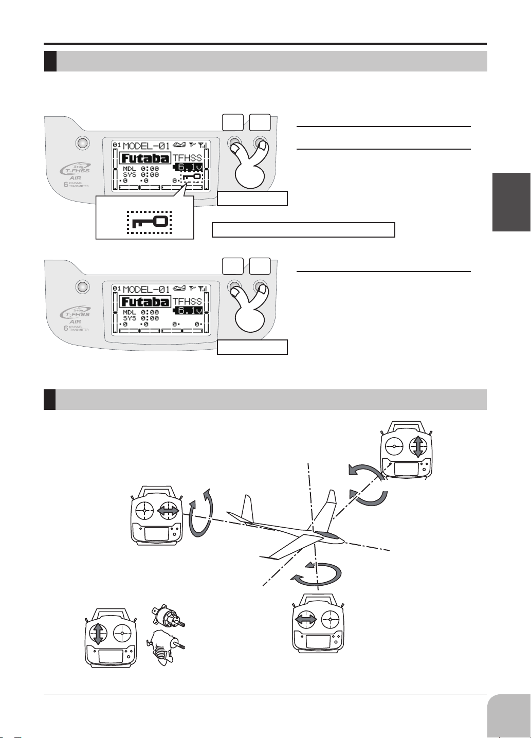
Keys Lock
To prevent the data from being changed by erroneous touching of the keys during flight, a
function which makes are keys impossible temporarily.
Keys Lock Display
Stick control
+ -
Press 1 second
Lock : Jog key, + key, - key, END key
+ -
Press 1 second
How to lock
The home screen is displayed.
1
Press the +key a nd -key simul-
2
taneously for about 1 second. "Key
mark" is displayed and the keys dis-
abled.
How to unlock
Press the +key a nd -key simul-
1
taneously for about 1 second in the
touch sensor locked state. The keys
enabled again.
Before use
Aileron stick
Engine/motor
Power
Throttle stick
Elevator Stick
Pitching axis
Roll axis
Yawing axis
Rudder stick
*Example Stick Mode2
25
Page 26
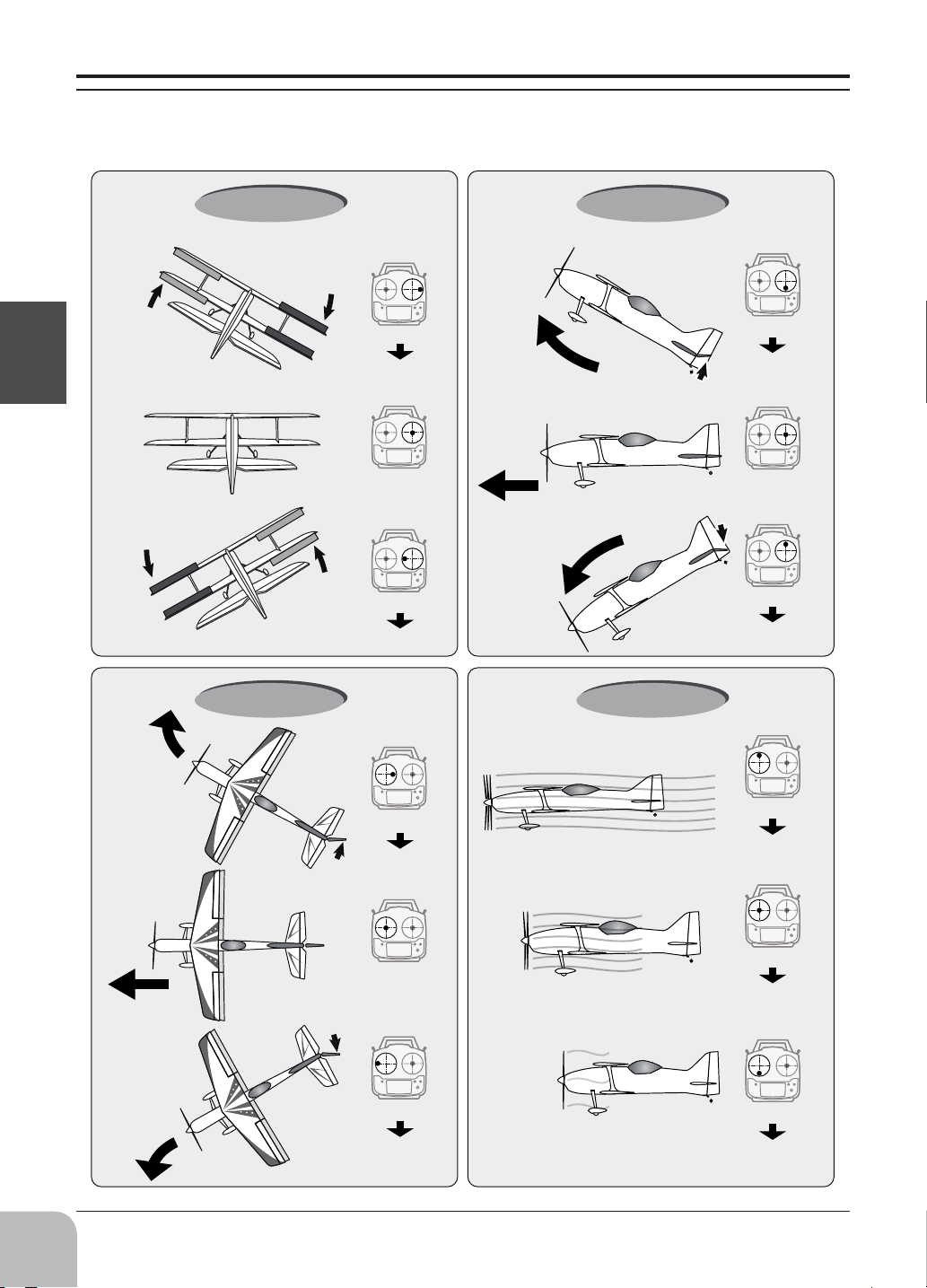
Stick control : Airplane Example
A general model example. (There is also a dierent operational model.)
*Example Stick Mode2
The left aileron
is in the down.
Before use
The left aileron
is in the up.
Roll axis Control
Pitch axis Control
Right roll
The right aileron
is to the up.
Nose Up
Aileron stick
To the right
Level flight
Level flight
Neutral
Left roll
The right
aileron is to
the down.
Aileron stick
To the left
Nose Down
Yaw axis Control Throttle Control
Elevator is a
up.
Elevator is a
down.
Elevator stick
UP
(moved to the bottom)
Neutral
Elevator stick
DOWN
(moved to the top)
26
Nose Right
Straight
Nose Left
A rudder is to
the right.
A rudder is to
the left.
Rudder stick
To the right
Neutral
Rudder stick
To the left
Hight
Middle
Slow
Throttle stick
HIGHT
(moved to the top)
Throttle stick
MIDDLE
(neutral)
Throttle stick
SLOW
(moved to the bottom)
Page 27
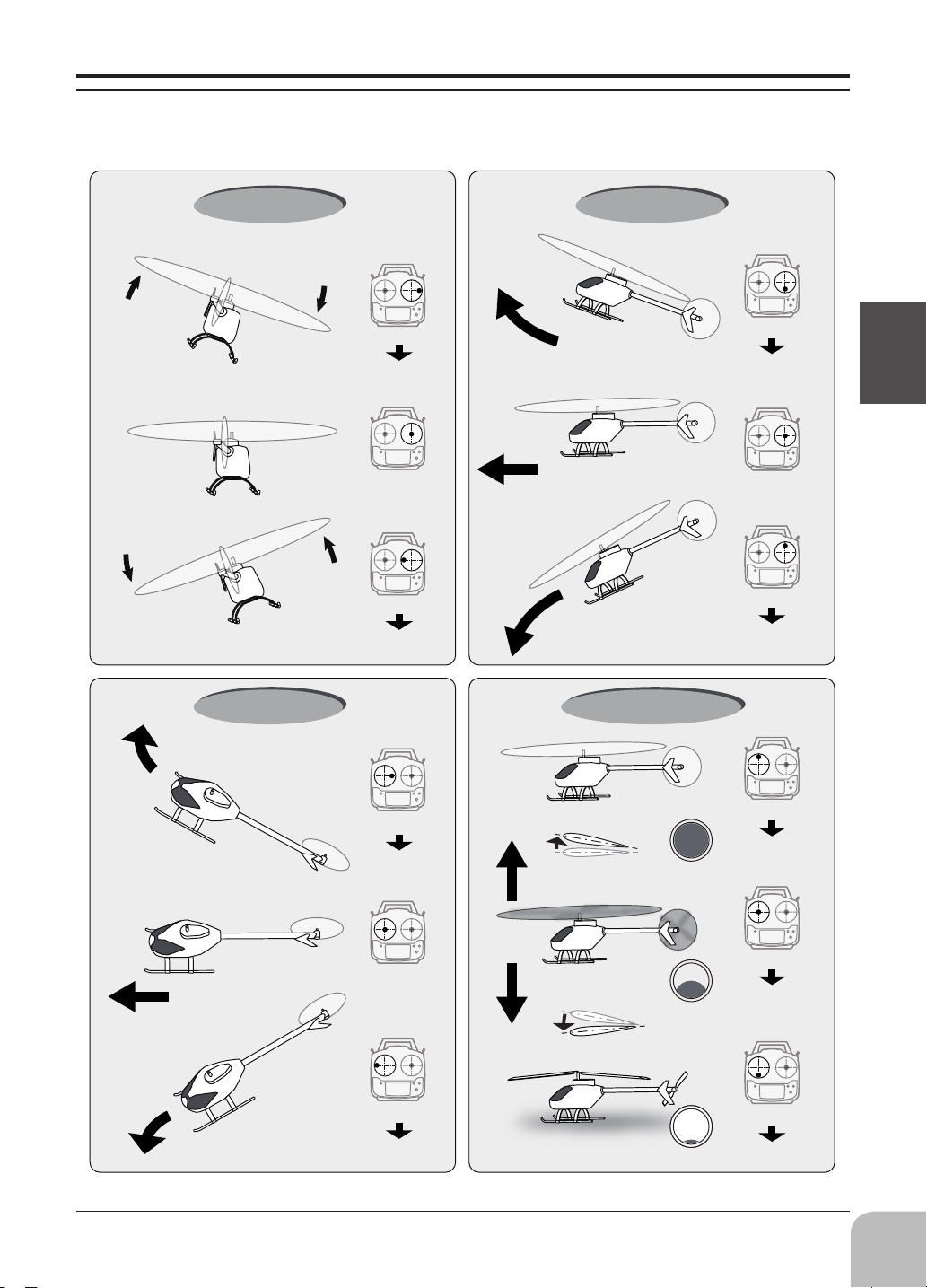
Stick control : Helicopter Example
A general model example. (There is also a dierent operational model.)
*Example Stick Mode2
Nose Right
Roll axis Control
Level flight
Left roll
Right roll
Nose Up
Aileron stick
To the right
Level flight
Neutral
Aileron stick
To the left
Pitch axis Control
Nose Down
Yaw axis Control Throttle /Pitch Control
Elevator stick
UP
(moved to the bottom)
Neutral
Elevator stick
DOWN
(moved to the top)
Before use
Straight
Nose Left
Rudder stick
To the right
Neutral
Rudder stick
To the left
Rise
Hovering
Descent
Pitch Down
HightPitch Up
Middle
Slow
(moved to the bottom)
Throttle stick
HIGHT
(moved to the top)
Throttle stick
MIDDLE
(neutral)
Throttle stick
SLOW
27
Page 28
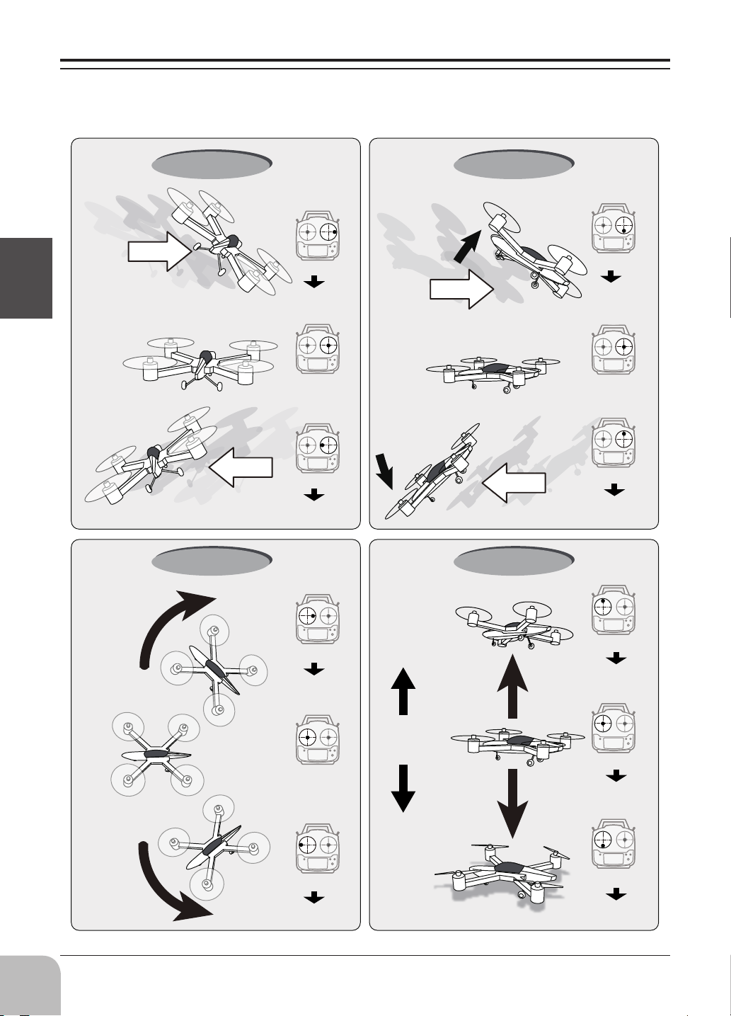
Stick control : Multicopter Example
A general model example. (There is also a dierent operational model.)
*Example Stick Mode2
Before use
Right slide
Left roll
Roll axis Control
Right roll
Hovering
Level flight
Left slide
Nose Up
Aileron stick
To the right
Hovering
Level flight
Neutral
Nose Down
Aileron stick
To the left
Pitch axis Control
Back slide
Front slide
Yaw axis Control Throttle Control
Elevator stick
UP
(moved to the bottom)
Neutral
Elevator stick
DOWN
(moved to the top)
28
Nose Right
Nose Left
Hovering
Level flight
Rudder stick
To the right
Neutral
Rudder stick
To the left
Rise
Hovering
Descent
Stop
Throttle stick
HIGHT
(moved to the top)
Throttle stick
MIDDLE
(neutral)
Throttle stick
SLOW
(moved to the bottom)
Page 29
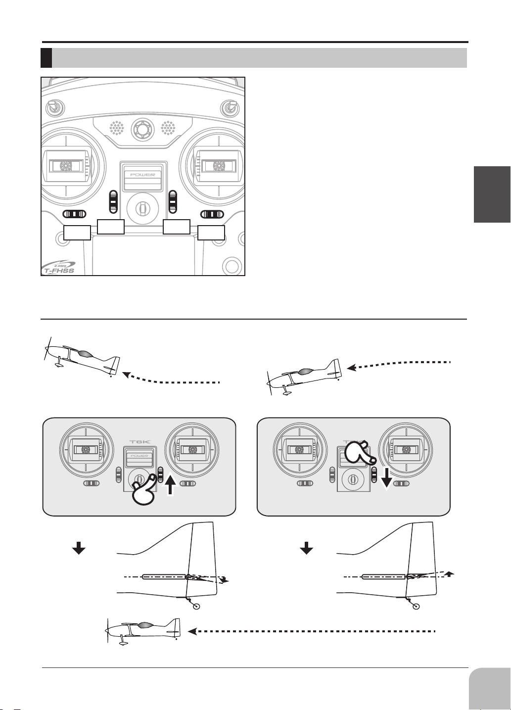
Digital Trims T1-T4
T3 T2
Digital trim operational example
This transmitter is equipped with 4 digital trims.
Each time you press a trim button, the trim position
moves one step. If you continue pressing it, the trim
position starts to move faster. In addition, when
the trim position returns to the center, the tone will
change. You can always monitor trim positions by
referencing the LCD screen.
*You can select the trim step amount and the display unit
on the home screen on the T1-T4 setting screen within the
linkage menu.
Note: The trim positions you have set will be stored in the
non-volatile memory and will remain there.
Before use
T1T4
*Example Stick Mode2
◆When an airplane nose up though an
elevator stick is neutral.
◆Elevator trim to down
Elevator neutral
Down
◆When an airplane nose down though
an elevator stick is neutral.
◆Elevator trim to up
Elevator neutral
Up
◆It's adjusted so that it may fly levelly.
29
Page 30
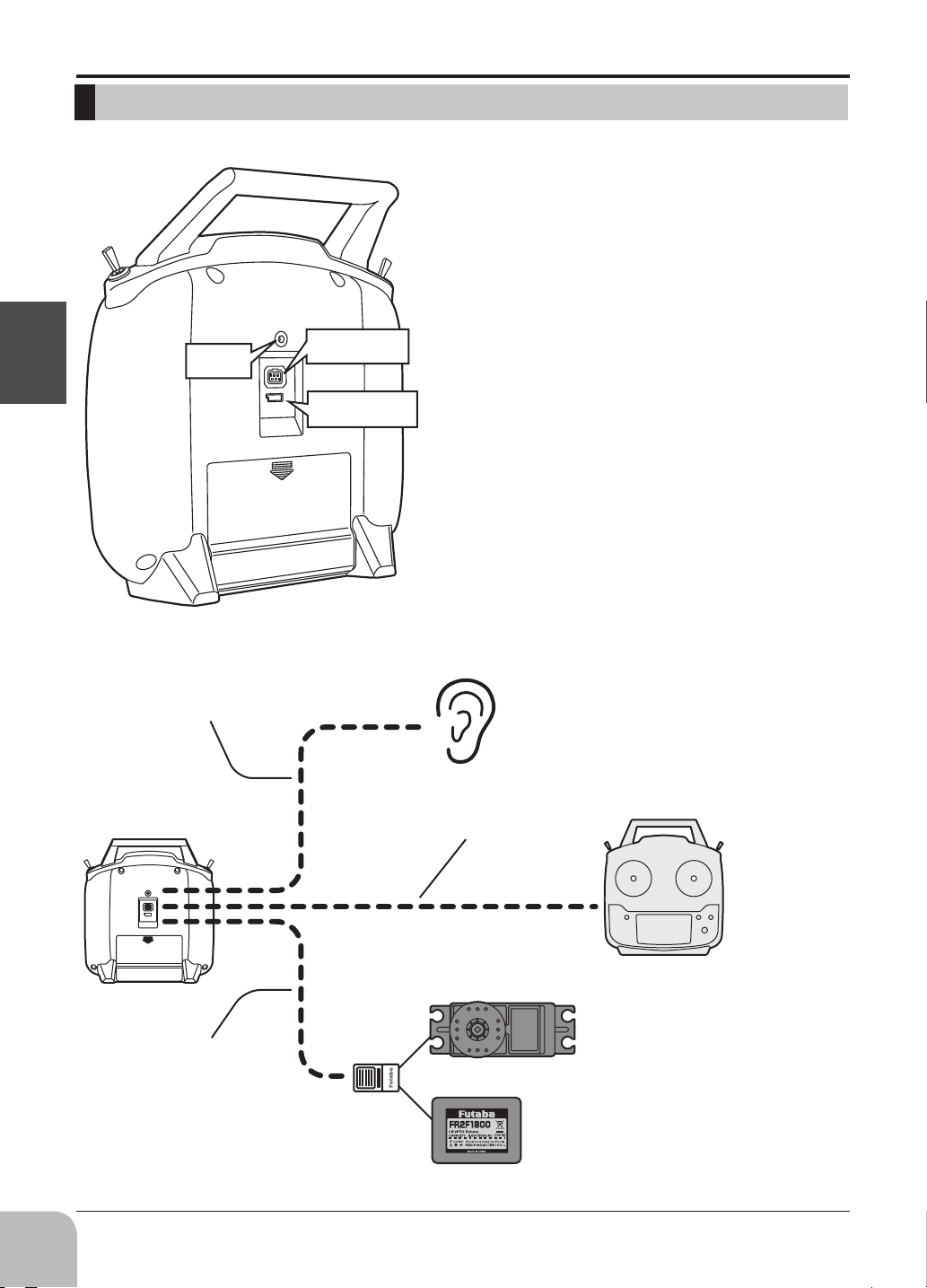
CONNECTOR / PLUG
Before use
Earphone
plug
Trainer function
connector
S.BUS
connector (S.I/F)
Earphone plug
The telemetry data can be listened to by plugging
in commercial 3.5mm earphones. (See the
telemetry item for the detailed setting.)
Trainer function connector
When you use the trainer function, connect the
optional trainer cable between the transmitters
for teacher and student.
*You can set the trainer function on the Trainer Function
screen.
S.BUS connector (S.I/F)
When setting an S.BUS servo and telemetry
sensor, connect them both here.
(Supply power by 3-way hub or 2-way cord.)
Earphone cable
3-way hub or
2-way cord
Telemetry data is heard
Trainer cable
Trainer system
S.BUS servo setting
30
Page 31

SWITCH ASSIGNMENT TABLE
• The factory default functions activated by the switches and VR for an 6K transmitter are shown
below.
• Most 6K functions may be reassigned to non-default positions quickly and easily.
• Basic control assignments of channels 5-6 are quickly adjustable in AUX-CH.
• Note that most functions need to be activated in the programming to operate.
AIRPLANE
Switch/VR 1AIL 1AIL1FLP 2AIL 2AIL1FLP ELEVON
Switch A --- --- --- --- ---
Switch B CH6 CH6 --- --- CH6
Switch C CH5 CH5 CH5 CH5 CH5
Switch D --- --- --- --- ---
VR --- --- --- --- ---
GLIDER
Switch/VR 1AIL 1AIL1FLP 2AIL 2AIL1FLP 2AIL2FLP
Switch A --- --- --- --- ---
SwitchB CH6 --- --- --- ---
SwitchC --- --- --- --- ---
SwitchD --- --- --- --- ---
VR CH5 Flap CH5 Flap Flap
Before use
HELICOPTER MULTI COPT
Switch/VR HELICOPTER
Switch A ---
SwitchB CH5
SwitchC IDLE-UP1/2
SwitchD THR-HOLD
VR ---
Remember that if you
assign primary control of a
channel to a switch which you
later use for other functions
(like dual/triple rates or
airbrakes), every time you use
that other function you will
also be moving the auxiliary
channel.
Don't assign the function
it inuences each other to the
same switch.
*When idle-up 1/2
and a throttle hold
were used.
Switch/VR MULTI COPT
Switch A ---
SwitchB ---
SwitchC ---
SwitchD CH5
VR ---
31
Page 32

RECEIVER AND SERVO CONNECTIONS
Aircraft
1AIL1FLP
1Aileron
1Flap
2AIL
2Aileron
CH
1AIL
1Aileron
1 Aileron Aileron Aileron1 Aileron Elevon1
2 Elevator Elevator Elevator Elevator Elevon2
3 Throttle Throttle Throttle Throttle Throttle
4 Rudder Rudder Rudder Rudder Rudder
5 --- Flap --- Flap Flap
2AIL1FLP
2Aileron
1Flap
ELEVON
Before use
6 --- --- Aileron6 Aileron6 ---
1AIL
Aileron1Servo
(CH1)
(WING TYPE)
Flap1Servo
(CH5)
Aileron 1
(CH1)
Aileron1Servo
(CH1)
2AIL+1FLP ELEVON
Flap1Servo
(CH5)
Elevon 1
(CH1)
(TAIL TYPE)
Elevon 2
(CH2)
2AIL 1AIL+1FLP
Aileron 6
(CH6)
32
Rudder
(CH4)
NORMAL V-TAIL
Elevator
Elevator
(CH2)
+Rudder
(CH2)
Elevator
+Rudder
(CH4)
Page 33

Helicopter
PIT
:Pitch Servo
CH HELICOPTER
(Swash Type)
1 Aileron (cyclic roll)
2 Elevator (cyclic roll)
3 Throttle
4 Rudder
5 Gyro
6 Pitch (collective pitch)
Multicopter
(Normal linkage type)
H-1: each servo linked
to the swashplate
independently.
AIL
:Aileron Servo
ELE
:Elevator Servo
Before use
CH MULTI COPTER
1 Aileron
2 Elevator
3 Throttle
4 Rudder
5 AUX
Mode
6
for Multicopter
controller
[ Connection example ]
Receiver
CH1 ←
CH2 ←
CH3 ←
CH4 ←
CH6 ←
When using an accessary (e.g,
shutter of a camera), use 5CH.
Motor
ESC
Motor
ESC
CH1 AIL
CH2 ELE
CH3 THR
CH4 RUD
MODE
(e.g, U
Multicopter
Controller
-port)
Motor
ESC
Motor
ESC
Battery
33
Page 34

Glider
CH
1 Aileron Aileron Aileron1 Aileron1 Aileron1
2 Elevator Elevator Elevator Elevator Elevator
3 Motor Motor Motor Motor Flap3
4 Rudder Rudder Rudder Rudder Rudder
5 --- Flap --- Flap Flap5
Before use
6 --- --- Aileron6 Aileron6 Aileron6
1Aileron
1AIL
1AIL
Aileron1Servo
(CH1)
1A+1F
1Aileron
1Flap
Flap1Servo
(CH5)
2AIL
2Aileron
(WING TYPE)
1AIL+1FLP
Aileron1Servo
(CH1)
2A+1F
2Aileron
1Flap
Aileron 1
(CH1)
2AIL
2A+2F
2Aileron
2Flap
Aileron 6
(CH6)
34
2AIL+1FLP 2AIL+2FLP
Aileron 1
(CH1)
Aileron 6
(CH6)
Flap1Servo
(CH5)
Aileron 1
(CH1)
Flap 5
(CH5)
*2AIL+2FLP type can't be used for a
motor glider.
(TAIL TYPE)
Rudder
(CH4)
NORMAL V-TAIL
Elevator
Elevator
(CH2)
+Rudder
(CH2)
Flap 3
(CH3)
Elevator
+Rudder
(CH4)
Aileron 6
(CH6)
Page 35

ADJUSTING THE LENGTH OF THE CONTROL STICKS
You may change the length of the control sticks to make
your transmitter more comfortable to hold and operate. To
Stick tip A Locking piece B
lengthen or shorten your transmitter’s sticks, first unlock
the stick tip by holding locking piece B and turning stick
tip A counterclockwise. Next, move the locking piece B
up or down (to lengthen or shorten). When the length feels
comfortable, lock the position by turning locking piece B
counterclockwise.
STICK LEVER TENSION ADJUSTMENT
You may adjust the tension of your sticks to provide the feel that you prefer for ying. To adjust
your springs, you’ll have to remove the rear case of the transmitter. First, remove the battery
cover on the rear of the transmitter. Next, unplug the battery wire, and remove the battery from
the transmitter. Next, using a screwdriver, remove the four screws that hold the transmitter’s rear
cover in position, and put them in a safe place. Gently ease off the transmitter’s rear cover. Now
you’ll see the view shown in the gure above.
Using a small Phillips screwdriver, rotate the adjusting screw for each stick for the desired spring
tension. The tension increases when the adjusting screw is turned clockwise. When you are
satised with the spring tensions, reattach the transmitter's rear cover. When the cover is properly
in place, reinstall and tighten the four screws. Reinstall the battery and cover.
Before use
Four screws are
removed and rear
case is removed.
+ screw is clockwise.
Stick tension maximum Stick tension minimum
+ screw is counter-clockwise.
Elevator
Aileron
StickStick
Mode 2 transmitter with rear case removed.
Do not loosen
the screw past
the top of the
frame, as this
will cause the
screw to rub on
the back case.
A screw touches a case.
※
Rudder
35
Page 36

WARNING & ERROR DISPLAYS
An alarm or error indication may appear on the display of your transmitter for a number of
reasons, including when the transmitter power switch is turned on, when the battery voltage is
low, and several others. Each display has a unique sound associated with it, as described below.
LOW BATTERY ERROR:
The
LOW BATTERY
LOW BATT
Before use
MIXING ALARM WARNING:
overridden.
will be issued at power-up are listed below. Throttle cut, idle-down, airbrake, motor SW,
ight MD, throttle-stick and condition. If turning a switch OFF does not stop the mixing
warning: The functions described previously probably use the same switch and the OFF
direction setting is reversed. In short, one of the mixings described above is not in the OFF
state. In this case, reset the warning display by pressing both +/-KEY at the same time.
Next, change one of the switch settings of the duplicated mixings.
*If "ESC mode" is chosen by "THR.CUT", a THR CUT will not start warning.
BACKUP ERROR:
The
BACKUP ERROR
occurs, all of the data will be reset when the power is turned on again.
Warning sound: Continuous beep until transmitter is powered off.
warning is displayed when the transmitter battery voltage drops below 4.1V.
Land your model as soon as possible before loss of control
due to a dead battery.
Warning sound: Several beeps repeated until problem resolved or
The
MIXING ALARM
whenever you turn on the transmitter with any of the mixing
switches active. This warning will disappear when the offending
switch or control is deactivated. Switches for which warnings
Warning sound: Several beeps (repeated continuously)
warning occurs when the transmitter memory is lost for any reason. If this
warning is displayed to ALARM you
Do not y when this message is displayed: all programming
has been erased and is not available. Return your transmitter to
Futaba for service.
A setup of warning of each sensor can be performed in
TLM
36
TELEMETRY
"TLM" mark is shown about
warning of TELEMETRY.
.
Page 37

LINK PROCEDURE (T6K/R3006SB)
Each transmitter has an individually assigned, unique ID code. In order to start operation, the
receiver must be linked with the ID code of the transmitter with which it is being paired. Once the
link is made, the ID code is stored in the receiver and no further linking is necessary unless the
receiver is to be used with another transmitter. When you purchase additional R3006SB receivers,
this procedure is necessary; otherwise the receiver will not work.
Link procedure
1. Place the transmitter and the receiver
close to each other within 20 inches(half
meter).
Less than 20 inches
2. Turn on the transmitter.
3. Select [MDL-SEL] and access the setup
screen shown below by press the jog key .
4. Use the jog key to select (NO LINK) or the
ID number next to LINK in the [MDL-SEL]
menu.
XXXXXXXXX
8. If the receiver ID is displayed in the
transmitter and the LED changed from red
blinking to a steady green light, linking is
complete. (The receiver linking wait state
ends in about 3 seconds.)
9. Check system operation. If the transmitter
and receiver are not linked, try linking
again.
* If there are many T-FHSS Air systems turned on in close
proximity, your receiver might have difculty establishing
a link to your transmitter. This is a rare occurrence.
However, should another T-FHSS Air transmitter/receiver
be linking at the same time, your receiver could link to
the wrong transmitter. This is very dangerous if you do
not notice this situation. In order to avoid the problem,we
strongly recommend you to double check whether your
receiver is really under control by your transmitter.
*When the linked transmitter power is turned on,
communications begins.
*When using 2 receivers, perform the linking operation the
same as the 1st receiver. (However, when 2 receivers are
used, the telemetry system cannot be used.)
*Link is required when a new model is made from a model
selection.
Before use
5. Hold down the jog key to enter the link
mode.
6. A chime from the transmitter notifies the
operator that the transmitter has entered
the link mode.
“Beep beep beep”
(Enters the link mode for 20 seconds)
In "Link" Mode
Receiver ON
7. Immediately turn on the receiver power.
The receiver will enter the linking state
(LED blinks red) about 3 seconds after the
receiver power is turned on.
WARNING
After the linking is done, please cycle receiver
power and check that the receiver to be linked
is really under the control of the transmitter.
Don't perform the linking procedure with
motor's main wire connected or with the
engine operating as it may result in serious
injury.
*Link is required when a new
model is made from a model
selection.
*When telemetry can't be used, try
a relink once again.
37
Page 38

RECEIVER NOMENCLATURE
DANGER
Before using the receiver, be sure to read the precautions listed in the following pages.
(Typical installation)
Mode Switch
Use the small plastic screw
driver that was included with your
receiver.
Switch is also used for the CH
Before use
mode selection. (CH6⇔S.BUS)
Mode switch
Antenna
R3006SB
LED Indication
Green Red Status
Off Solid No signal reception
Solid Off Receiving signals
Alternate blink Unrecoverable error (EEPROM, etc.)
LED
S.BUS2 port
(SB2/B)
1:Aileron servo
2:Elevator servo
3:Throttle servo (engine)
3:Motor controller (electric)
4:Rudder servo
5:Gear servo (airplane)
5:Gyro gain(Helicopter)
6:Flap servo (airplane)
6:Pitch servo(Helicopter)
Battery
Switch
HUB
Telemetry Sensor
Telemetry Sensor
HUB
Telemetry Sensor
38
DANGER
Don't connect a connector, as shown in a
before figure.
*It will short-circuit, if connected in this way. A short circuit
AIRPLANEss the battery terminals may cause abnormal
heating, re and burns.
Don't connect servo for conventional system
to S.BUS2 port.
*Digital servo for conventional system→ It does not operate.
*Analog servo → It may cause abnormal heat, re and burning.
WARNING
S.BUS2 connectors
Don't connect an S.BUS servo / gyro to
S.BUS2 connector.
Receiver
Do not insert either a switch
or battery in this manner.
Page 39

R3006SB CH MODE
The R3006SB receiver is a very versatile unit. It has 6 PWM outputs and S.BUS2 outputs. Additionally
the SB/6 outputs can be changed from channels PWM 6 channel to S.BUS.
How to change the R3006SB Channel mode
(S.BUS⇔6CH )
The R3006SB is capable of changing its channel
allocations as described in the table below.
1 Turn on the receiver. (At this moment, the
transmitter should be off.) Then, LED blinks
RED in about 3 seconds. Next, wait until it
becomes solid RED.
2 Press and hold the Mode switch more than 5
seconds.
3 Release the button when the LED blinks RED
and GREEN simultaneously.
4 The receiver is now in the "Operation CH Set"
mode. At this moment, the LED indicates
current set status through ashing a pattern
that corresponds to the CH mode.
*Cannot exit this CH setting mode before the operation mode is
xed.
**See the below table that shows correspondence between "CH
mode" and way of ashing LED.
***Default CH mode is "Mode A (6CH)".
5 By pressing the Mode switch, the operation
CH is switched sequentially as " Mode A"
"Mode B" "Mode A"....
6 The operation mode will be set by pressing
the Mode switch more than 2 seconds at the
desired CH mode.
7 Release the button when the LED blinks
RED and GREEN simultaneously. Then, the
operation CH is xed.
6 After confirming the operation CH mode is
changed, turn off and back on the receiver
power.
*The “Operation CH Set” mode cannot be changed during the
receiver communicates to the transmitter.
Before use
R3006SB CH Mode table
Mode A Mode B
6/SB 6CH S.BUS
Red LED blink 1 time 2 time
Default CH mode
PWM 6ch
WARNING
S.BUS2 connectors
Don't connect servo for
conventional system to S.BUS
port.
*Digital servo for conventional system→
It does not operate.
*Analog servo → It may cause abnormal
heat, re and burning.
S.BUS
39
Page 40

RECEIVER's ANTENNA INSTALLATION
The R3006SB has two antennas. In order to maximize signal reception and promote safe
modeling Futaba has adopted a diversity antenna system. This allows the receiver to obtain RF
signals on both antennas and y problem-free.
*Must be kept as straight as possible.
Antenna
Coaxial cable
To obtain the best results of the diversity
function, please refer to the following
Before use
instructions:
1. The two antennas must be kept as straight
as possible. Otherwise it will reduce the
effective range.
2. The two antennas should be placed at 90
degrees to each other.
Antenna
This is not a critical figure, but the most
important thing is to keep the antennas
away from each other as much as possible.
Larger models can have large metal
objects that can attenuate the RF signal. In
this case the antennas should be placed
at both sides of the model. Then the best
RF signal condition is obtained at any ying
attitude.
3. The antennas must be kept away from
conductive materials, such as metal,
carbon and fuel tank by at least a half
inch. The coaxial part of the antennas does
not need to follow these guidelines, but do
not bend it in a tight radius.
4. Keep the antennas away from the motor,
ESC, and other noise sources as much as
possible.
Antenna
40
*The two antennas should be placed at 90 degrees to each other.
*The Illustration demonstrates how the antenna should be placed.
*Receiver Vibration and Waterproofing: The receiver contains precision electronic parts. Be sure to avoid vibration,
shock, and temperature extremes. For protection, wrap the receiver in foam rubber or other vibration-absorbing
materials. It is also a good idea to waterproof the receiver by placing it in a plastic bag and securing the open end of the
bag with a rubber band before wrapping it with foam rubber. If you accidentally get moisture or fuel inside the receiver,
you may experience intermittent operation or a crash. If in doubt, return the receiver to our service center for service.
Page 41

Rubber
grommet
Brass eyelet
Wood screw
Servo mount
2.3-2.6mm nut
washer
Rubber
grommet
Brass eyelet
Servo mount
2.3-2.6mm screw
(Helicopter) (Airplane/Glider)
MOUNTING THE SERVO
SAFETY PRECAUTIONS
when you install receiver
and servos
WARNING
Connecting connectors
Be sure to insert the connector until it stops
at the deepest point.
Servo lead wires
To prevent the servo lead cable from being
broken by vibration during flight, provide a
little slack in the cable and fasten it at suitable
points. Periodically check the cable during daily
maintenance.
Margin in the lead wire.
Fasten about 5-10cm
from the servo outlet so
that the lead wire is neat.
MOUNTING THE POWER
SWITCH
When mounting a power switch to an airframe,
make a rectangular hole that is a little larger than
the total stroke of the switch so that you can turn
the switch ON/OFF without binding.
Avoid mounting the switch where it can be
covered by engine oil and dust. In general, it is
recommended to mount the power switch on the
side of the fuselage that is opposite the mufer.
How to protect the receiver from
vibration and water
Wrap the receiver with something soft such
as foam rubber to avoid vibration. If there is
a chance of getting wet, put the receiver in
a waterproof bag or balloon to avoid water.
Receiver's antenna
Never cut the receiver's antenna. Do not
bind the receiver's antenna with the cables
for servos.
Locate the receiver's antenna as far as
possible from metals or carbon fiber
components such as frames, cables, etc.
*Cutting or binding the receiver's antenna will
reduce the radio reception sensitivity and range,
and may cause a crash.
Servo throw
Adjust your system so that pushrods will not
bind or sag when operating the servos to
the full extent.
*If excessive force is continuously applied to a
servo, the servo could be damaged due to force
on the gear train and/or power consumption
causing rapid battery drain.
Mounting servos
Use a vibration-proof rubber (such as
rubber grommet) under a servo when
mounting the servo on a servo mount. And
be sure that the servo cases do not touch
directly to the metal parts such as servo
mount.
*If the servo case contacts the airframe directly,
vibration will travel to and possibly damage the
servo.
Before use
41
Page 42

RANGE CHECK THE RADIO
A range check must be performed before the rst ight of a new model. It is not necessary to do
a range check before every ight (but is not a bad idea to perform a range check before the rst
ight of each day). A range check is the nal opportunity to reveal any radio malfunctions, and to
be certain the system has adequate operational range.
We have installed a special “Power Down Mode” in the T6K in order to perform an operational
ground range check. During this mode, the RF power is reduced in order to test the operational
range of the T6K.
To activate the Power Down Mode and Perform A Range Check:
1) To activate the “Power Down Mode” please hold
down the JOG KEY and then turn the transmitter switch
on. A power mode screen is displayed. Press the JOG
KEY to select the Power Down function. When this
Before use
mode is active the red LED on the lighting from of
the transmitter will provide users with an audible and
visual indication that the transmitter is in the “Power
Down Mode”. Audibly, the transmitter will beep one
time every three seconds. Visually, the LCD screen will
display “POWER DOWN MODE”. The words “POWER
DOWN MODE” will blink as an additional reminder
that the transmitter is in the “Power Down Mode”.
2) With the “Power Down Mode” activated, walk away from the model while simultaneously operating the controls.
Have an assistant stand by the model and signal what the controls are doing to conrm that they operate correctly. You
should be able to walk approximately 30-50 paces from the model without losing control.
3) If everything operates correctly, return to the model. Push END KEY and complete power down mode. Set the
transmitter in a safe yet accessible location so it will be within reach after starting the engine. Be certain the throttle
stick is all the way down, and then start the engine. Perform another range check with your assistant holding the model
and the engine running at various speeds.
If the servos jitter or move inadvertently, there may be a problem. Do NOT y the aircraft! Look for loose servo
connections or binding pushrods. Also be certain that the battery has been fully charged.
4) NEVER start ying when the “Power Down Mode” is active.
Servo test operation at the time of Power Down Mode:
During Power Down mode, you can use automatic servo testing to check the range of a specied servo (it moves to
right and left slowly).
1) A "SERVO" is chosen from a menu.
2) JOG KEY is moved to a side and 2 pages is called. Next, JOG KEY is moved down and CH is displayed.
3) CH of the servo which wants to operate is chosen. Then, the + KEY is pressed and it is made ACT.
The servo selected during Power Down Mode operates alone, allowing you to check its operation.
It is during Power Down Mode starting, and if "SERVO TEST" is turned ON, it will move.
*In the Power Down Mode, the throttle servo does not operate.
*Helicopter mode, condition is xed to NOR.
Select the "OFF" and
press the Jog key.
A screen opens without
outputting power.
The receiver does not
operate.
Select the "ON" and
press the Jog key.
Power is usually
outputted from power
mode.
42
DANGER
NEVER start flying when the “Power Down
Mode” is active.
*Control is impossible and your model crashes.
Page 43

S.BUS/S.BUS2 INSTALLATION
This set uses the S.BUS/S.BUS2 system. The wiring is as simplified and clean mounting as
possible, even with models that use a large number of servos. In addition, the wings can be
quickly installed to the fuselage without any extraneous wiring by the use of only one simple
wire, even when there are a large number of servos used.
●When using S.BUS/S.BUS2, special settings and mixes in your transmitter may be unnecessary.
●The S.BUS/S.BUS2 servos memorize the number of channels themselves. (Settable with the T6K)
●The S.BUS/S.BUS2 system and conventional system (receiver conventional CH used) can be mixed.
S.BUS Glider usage example
Receiver: R3006SB
HUB×1 (Optional)
i-i Connector (Optional) i-i Connector (Optional)
i Connector (Optional)
* i Connector makes S.BUS
connection of SVi servo to receiver.
Servo: S3173SVi×7 (Optional)
* i-i Connector makes S.BUS connection
of SVi servo to SVi servo.
Before use
i-i Connector (Optional)
S.BUS Aerobatic plane usage example
Throttle servo: BLS173SV ( Optional )
Battery: FR2F1800 ( Optional )
Switch: HSW-L
Receiver: R3006SB
Aileron servo: BLS174SV×2 ( Optional )
HUB×3 ( Optional )
Rudder Servo: BLS175SV×1 ( Optional )
Elevator servo: BLS173SVi×2 ( Optional )
43
Page 44

S.BUS WIRING EXAMPLE
Receiver
Battery
●S.BUS Servo
Since the channel number is
memorized by the S.BUS itself,
any connector can be used.
Before use
MODEB(S.BUS)
CH MODE
HUB
SB/6
Port
S.BUS Servo
HUB
(Another power supply)
HUB
Switch
HUB
HUB
Switch
Battery
Optional Parts
Terminal box
●
Four connectors can be inserted
HUB
WARNING
Power supply
Please make sure that you use a
battery that can deliver enough
capacity for the number and
kind of servos used. Alkaline
batteries cannot be used.
●When separate power supply used
When a large number of servos are used or
when high current servos are used, the servos
can be driven by a separate power supply by
using a separate Power Supply 3-way Hub.
44
Orange
S.BUS Servo
HUB
Three connectors
can be inserted.
Green
Optional PartsOptional Parts
HUB
Used when using
a separate power
supply battery.
Page 45

S.BUS2 SYSTEM
When using the S.BUS2 port, an impressive array of telemetry sensors may be utilized.
S.BUS2 TABLE
Receiver port
S.BUS Servo
S.BUS Gyro
S.BUS2
S.BUS2
Servo
Gyro
Telemetry sensor
S.BUS ○ ○ ×
S.BUS2
(※)
× (※) ○ ○
Don't connect S.BUS Servo,
S.BUS Gyro to S.BUS2 connector.
S.BUS servos and gyros and S.BUS2 servos and gyros must be used in the
correct receiver ports. Please refer to the instruction manual to make sure
you connect to the correct one.
CH Mode is set to ModeB.
Before use
HUB
HUB HUB HUB
S.BUS2 ServoS.BUS Servo
S.BUS2 servo
Connection is possible
S.BUS2 gyro
Connection is possible
Telemetry sensor
Connection is impossible
S.BUS servo
Connection is impossible
S.BUS2
GYRO
Rudder Servo
Telemetry
Sensor
+
45
Page 46

S.BUS/S.BUS2 DEVICE SETTING
S.BUS/S.BUS2 servos or a telemetry sensor can be connected directly to the T6K. Channel
setting and other data can be entered for the S.BUS/S.BUS2 servos or sensors.
Back of T6K
Before use
3-way hub
or Y-harnesses
S.BUS/S.BUS2
device
(S.BUS/S.BUS2
Servo)
(Telemetry sensor)
Receivers
Battery
1. Turn on the transmitter power.
2. Call the setup screen.
Servo: → S.BUS
3. Connect the S.BUS device and battery you
want to set with a 3-way hub or Y-harnesses
as shown in the gure.
4. Perform setting in accordance with each
screen.
5. This sets the channel and other data for each
S.BUS servo, or telemetry device to be used
with the S.BUS device or receiver.
46
Page 47

TELEMETRY SYSTEM
The R3006SB receiver features bi-directional communication with a T-FHSS Air Futaba
transmitter using the S.BUS2 port. Using the S.BUS2 port an impressive array of telemetry
sensors may be utilized. It also includes both standard PWM output ports and S.BUS output
ports.
*Telemetry is available only in the T-FHSS Air mode.
*The telemetry function requires the corresponding receiver (R3006SB).
*The T6K will enter and keep the ID number of the R3006SB that it is linked to.
*When you use two or more R3006SB, set telemetry mode to INH.
●Telemetry sensor (sold separately)
Your aircraft's data can be checked in the
transmitter by connecting various telemetry
sensors to the S.BUS2 connector of the
receiver.
T6K
Before use
Signal
Info
Switch
S.BUS2
Port(SB2/B)
●Slot Number
Servos are classified by channel, but sensors
are classified by “slot” . Since the initial slot
number of the T6K is preset at each sensor,
the sensors can be used as is by connecting
them. There are 1~31 slots.
Airplane in the sky
●Receiver Voltage
●Altitude
●Engine Temperature
●Propeller R.R.M
Battery voltage is
displayed at the transmitter.
Info
HUB
Receiver
Temperature
Sensor
RPM
Sensor
Altitude
Sensor
Slot 1
Slot 2
Slot 3 ~ 5
Transmitter
Displayed at the transmitter
47
Page 48

Common function
The setting screens are called from the following menu. All the functions common to
airplane, helicopter, glider, and multicopter model types are shown here.
To menu screen
by holding down
the + key
● When the + key is pressed for
1 second, the menu screen is
displayed.
● First set the throttle
to slow.
● When the END key is
pressed, the display
returns to the home
Common function
screen.
MENU
● Then turn on the
power.
END
(Home screen)
+
(1 second)
MENU
1/4
MENU
2/4
MENU
3/4
(Selection)
● Move the cursor
(highlighted) up and
down and to the left and
right with the Jog key and
select the function.
The cursor can be moved
over several pages.
(Calling the setting screen)
● Press the Jog key to open the
setting screen.
48
Page 49

key / LCD
+ key
●- key●
END key
●
●Jog key
■ Function
◆ MENU 1/3 ◆ MENU 2/3 ◆ MENU 3/3
MDL SEL
MDL TYP
MDL NAM
F/S
P.50
P.53
P.55
P.57
PRMTR
P.MIX
AUX CH
SERVO
P.63
P.68
P.71
P.72
TIMER
TRAINR
Common function
P.92
P.94
E POINT
TRIM
SUB TRM
REVERS
P.59
P.60
P.61
P.62
TLMTRY
SENSOR
S.BUS
M TRANS
P.73
P.86
P.88
P.91
49
Page 50

MDL SEL
Model select(Select / RX type / Link / Reset / Copy)
Function
This function is used when calling and copying
model data stored in the transmitter. The selected
model data can also be reset. System changes
Model select(SELE)
The model data of up to 30 models can be stored in the transmitter. This function is used when
calling saved model data.
Receiver selection(RX)
The R3006SB supplied with the transmitter, employs the T-FHSS Air system. When you want to use
an S-FHSS receiver, switch to S-FHSS here. However, the telemetry function cannot be used with the
S-FHSS system.
Link(LINK)
When linking with the receiver, the transmitter is set to the link mode here. The ID number of the
currently linked receiver is displayed.
Data reset (RES)
The model data currently in use can be reset to its initial value. However, it does not Reset other
Common function
than the following of a parameter.
[ The function reset in a parameter : TELEMETRY mode, STK POSI ALRM ]
Model copy(COPY)
This is the model data copy function. It is convenient when you want to store model data as backup
or build a number of models with the same data settings.
● The data of the model memory currently in use can be copied to another model memory.
(T-FHSS Air, S-FHSS) matched to the receiver type
and linking with the receiver are also done here.
(Common)
Method
Calling the setting screen
① Call the menu screen from the
home screen by pressing the + key
for 1 second.
+
(1 second)
Model select
RX system
● Select the setting
item with the Jog
key.
50
Link
Reset
② Select
from the menu with the Jog
key.
"MDL SEL"
③ Open the setting screen by
pressing the Jog key.
(Model number:1 〜 30)
● Original data : Model type
Model name
● System(T-FHSS Air or S-FHSS)
● Link receiver ID
If telemetry is used, the receiver
ID is needed.
Page 51

Model select
① Select the SELECT item and then
select the model number by
pressing the + key or – key.
+ -
or
Selection range:1 〜 30
For safety, a double setting system is used. When a change is cancelled after the confirmation message is
displayed, the change is not made when moved to another setting item by Jog key.
② Press the Jog key for 1
second.
(1 second)
● Conrmation message
"sure?" blinks.
③ Select the model by pressing the
Jog key.
● A confirmation "beep
beep" sounds to show that
selection is complete.
RX type
① Select the RX item and then select
T-FHSS Air or S-FHSS by pressing
the + key or – key.
+ -
or
● Conrmation message
"sure?" blinks.
② RX type change by pressing the
Jog key.
● A confirmation "beep"
sounds is complete.
Selection range:T-FHSS Air,
S-FHSS
Common function
For safety, a double setting system is used. When a change is cancelled after the confirmation message is
displayed, the change is not made when moved to another setting item by Jog key.
Link
① Select the LINK item and then press the Jog key
for 1 second.
(1 second)
● T-FHSS Air only. S-FHSS does not enter the link
mode. Use the receiver link button to link the
receiver.
For safety, linking must not be performed while the drive motor or engine is running. When linking is
complete, turn the power o and on and check operation.
② Enters the link mode for about 20 seconds.
During this time, bring the receiver near the
transmitter and turn on the receiver power.
When linking, the receiver ID is displayed.
● In the link mode, a confirmation "beep
beep beep" sounds and the time
remaining is displayed on the screen.
When 20 seconds have elapsed, a
continuous beep sounds and the link
mode is exited.
*Link is required when a new model is made from a model selection.
51
Page 52

Date reset
CAUTION
① Select the REST item and then press the Jog
key for 1 second.
(1 second)
● Conrmation message "sure?" blinks.
For safety, a double setting system is used. When a change is cancelled after the conrmation message
is displayed, the change is not made when moved to another setting item by Jog key.
Only the throttle channel (CH3) initial setting is REV (reverse). Thoroughly
check the Hi and Low directions of the engine or motor used and be careful that
they do not suddenly run at full speed. Even after data reset, CH3 is reversed.
② Date reset by pressing the Jog key.
● A confirmation "beep" sounds and
"COMPLETE" is displayed on the screen is
complete.
Common function
Model copy
① Select the COPY item and the select
the model number of the copy
destination by pressing the + key
or – key.
② Press the Jog key for 1
second.
(1 second)
③ Copy the model by pressing the
Jog key.
+ -
or
Selection range:1 〜 30
● Conrmation message
"sure?" blinks.
● A confirmation "beep"
sounds and "COMPLETE"
is displayed on the screen
to show that copying is
complete.
For safety, a double setting system is used. When a change is cancelled after the confirmation message is
displayed, the change is not made when moved to another setting item by Jog key.
52
MDL SEL PAGE 2
● Original data : Model type
Model name
● Copy place : Model type Model
name
Page 53

MDL TYP
Model type
(Common)
Function
Six swash types are available for helicopters.
Five types of main wings and two types of tail
wings are available for airplanes and gliders.
Functions and mixing functions necessary for each
model type are set in advance at the factory.
(WING TYPE: GLIDER)
1AIL
Aileron1Servo
(CH1)
1AIL
Aileron1Servo
(CH1)
1AIL1FLP
Flap1Servo
(CH5)
1AIL1FLP
Aileron1Servo
(CH1)
(WING TYPE: AIRPLANE)
Flap1Servo
(CH5)
Aileron1Servo
(CH1)
Rudder
(CH4)
2AIL
Aileron 1
(CH1)
2AIL
Aileron 1
(CH1)
(TAIL TYPE)
NORMAL V-TAIL
Note: The Model Type function automatically
selects the appropriate output channels,
control functions, and mixing functions for the
chosen model type.
When the Model Type selection command
is accessed, all of the data in the active
memory is cleared (except the following
swash type.) Be sure that you don’t mind
losing this data, or back it up to another
memory using the copying functions.
2AIL2FLP
Flap 5
(CH5)
Aileron 1
(CH1)
*2AIL+2FLP type can't be used for a
motor glider.
Flap 3
(CH3)
Aileron 6
(CH6)
ELEVON
Elevon 1
(CH1)
Elevon 2
(CH2)
Aileron 6
(CH6)
Aileron 6
(CH6)
2AIL1FLP
Aileron 1
(CH1)
2AIL1FLP
Aileron 6
(CH6)
Flap1Servo
(CH5)
Flap1Servo
(CH5)
Common function
(Normal linkage type)
H-1: each servo linked
to the swashplate
independently.
AIL
:Aileron Servo
ELE
:Elevator Servo
PIT
:Pitch Servo
Elevator
(CH2)
Elevator
+Rudder
(CH2)
Elevator
+Rudder
(CH4)
(SWSH TYPE: HELICOPTER)
53
Page 54

Model type
① Select the "TYPE" item and
then select the model type by
pressing the + key or – key.
+ -
or
● The new model type is
displayed on the screen.
② Press the Jog key for 1 second.
(1 second)
● Confirmation message
"sure?" blinks.
③ Model type change by pressing
the Jog key.
● A confirmation "beep"
sounds is complete.
For safety, a double setting system is used. You need to conrm your
setting changes by pressing the jog key. If you fail to press the jog key
and see "COMPLETE" on your screen, your changed are not saved.
Wing type(for Airplane /Glider)
① Select the "WING" item and
then select the swash type by
pressing the + key or – key.
+ -
Common function
For safety, a double setting system is used. When a change is cancelled
after the conrmation message is displayed, the change is not made
when moved to another setting item by Jog key.
or
② Press the Jog key for 1 second.
(1 second)
● Confirmation message
"sure?" blinks.
Tail type(for Airplane /Glider)
① Select the "TAIL" item and
then select the swash type by
pressing the + key or – key.
② Press the Jog key for 1 second.
(1 second)
+ -
or
● Confirmation message
"sure?" blinks.
Selection range:
AIRPLANE, HELICOPTER, GLIDER,
MULTI COPT
③ Swash type change by pressing
the Jog key.
● A confirmation "beep"
sounds is complete.
Selection range:1AIL, 1AIL1FLP,
2AIL, 2AIL1FLP, ELEVON(Airplane),
2AIL2FLP(Glider)
③ Swash type change by pressing
the Jog key.
● A confirmation "beep"
sounds is complete.
54
For safety, a double setting system is used. When a change is cancelled
after the conrmation message is displayed, the change is not made
when moved to another setting item by Jog key.
Swash type(for Heli)
① Select the "SWASH" item and
then select the swash type by
pressing the + key or – key.
+ -
or
For safety, a double setting system is used. You need to conrm your
setting changes by pressing the jog key. If you fail to press the jog key
and see "COMPLETE" on your screen, your changed are not saved.
② Press the Jog key for 1 second.
(1 second)
● Confirmation message
"sure?" blinks.
Selection range:NORMAL,
V-TAIL
③ Swash type change by pressing
the Jog key.
● A confirmation "beep"
sounds is complete.
Selection range:H-1, HR3,
H-3, HE3, HN3, H-2
Page 55

MDL NAM
Model name / User name
(Common)
Function
A model name is inputted into each model in
T6K.
User name is inputted into T6K.
Model name setting(MDL NAME)
This function assigns a name to the model data. The model name is displayed on the top row of the
home screen. This serves to prevent model memory mistakes if the current aircraft name or other
name is entered.
● Up to 8 characters can be set.
User name setting(USR NAME)
The user name displayed on the home screen can be set. (When a user name is not set, the Futaba
logo is displayed) When the home screen display is changed to USR-NAME by PARAMETER, the set
user name is displayed on the home screen.
● Up to 8 characters can be set.
Method
Calling the setting screen
① Call the menu screen from the
home screen by pressing the + key
for 1 second.
+
(1 second)
Model name
User name
Model name
① Move the cursor to the model
name digit you want to change by
pressing the + key or – key.
+ -
or
② Select
from the menu with the Jog
key.
② Move the cursor to the
candidate character you
want to change with the
Jog key.
"MDL NAM"
Common function
③ Open the setting screen by
pressing the Jog key.
(Reset)
(Candidate characters)
● Characters that can be entered ;
Numeric/upper case alphabet/
lower case alphabet
③ Change the character by pressing
the Jog key.
Set the model name by repeating steps ① to ③ above.
Reset method:
Jog key is pressed in the state in which the cursor was moved to RESET by Jog key, the model name
returns to its initial setting.
When the cursor is moved to any digit of the model name by + key or – key and the
55
Page 56

User name
① Move the cursor to the user name
digit you want to change by
pressing the + key or – key.
+ -
or
Set the user name by repeating steps ① to ③ above.
Reset method: When the cursor is moved to any digit of the user name by + key or – key and the Jog
key is pressed in the state in which the cursor was moved to RESET by Jog key, the user name returns
to its initial setting (Futaba logo).
② Move the cursor to the
candidate character you
want to change with the
Jog key.
③ Change the character by pressing
the Jog key.
Displaying the user name on the home screen
The set user name can be displayed on the home screen. (When a user name is not set, the Futaba logo is
displayed.) When the home screen display is changed to USR-NAME by PARAMETER, the set user name is
displayed.
Common function
Calling the setting screen
① Call the menu screen from the
home screen by pressing the + key
for 1 second.
+
(1 second)
Parameter
Select "HOME-DSP" from the
①
parameter 2 page with the Jog key.
② Select
from the menu with the Jog
key.
② Select "U-NAME" by pressing
the + key or – key.
"PRMTR"
+ -
③ Open the setting screen by
pressing the Jog key.
③ End setting by pressing the
END key.
END
56
Page 57

F/S
WARNING
Fail safe
Function
When normal radiowaves cannot be received due
to noise and interference, the NOR mode, which
holds the servo of each channel in its position
immediately before reception was lost, or F/S (Fail
Safe) mode, which moves the servo of each channel
to a preset position, can be selected. When T-FHSS
Air is selected, the battery fail safe voltage can be
set.
●When the throttle channel was reversed by servo
reverse function, the F/S data is also reversed.
(Throttle channel only) If the receiver battery
voltage drops below the set value when the fail
safe mode was selected, the battery fail safe
function moves the servo to a preset position.
●The S-FHSS fail safe voltage is 3.8V.
●Only the throttle channel battery fail safe function
can be turned on and off.
Method
Calling the setting screen
① Call the menu screen from the
home screen by pressing the + key
for 1 second.
② Select
from the menu with the Jog
key.
+
(1 second)
(Common)
●When this function was performed reset the battery
fail safe function by the following method and
immediately land.
Reset method:
temporarily disabled by moving the throttle stick to the slowest
side. However, after 30 seconds the battery fail safe function will
return to the battery fail safe state.
For safety, always set the fail safe functions.
●Remember to set the throttle channel fail safe function so that
the servo moves to the maximum slow side for airplanes and
to the slow side from the hovering position for helicopters.
Crashing of the model at full high when normal radio waves
cannot be received due to interference, etc., is very dangerous.
●If the battery fail safe is reset by the throttle stick, it may
be mistaken for an engine malfunction and will be reset at
throttle slow and the model will continue to y. If you have
any doubts, immediately land.
"F/S"
The battery fail safe function can be
③ Open the setting screen by
pressing the Jog key.
Common function
● Select the setting item
with the Jog key.
■
Mode selection
① Select the mode by
pressing the + key or
– key at the MODE
item of each channel.
+ -
Fail safe
or
(Range)
NOR, F/S
F/S Position
Mode select Battery-F/S : ON/OFF
(When F/S mode was selected)
■ F/S position
② In the mode selected state, set the F/
S position by holding the stick of that
channel in the position you want to set
and press the Jog key for 1 second.
● A conrmation beeping sounds to
show that the servo position was
set.
■
When using the B-F/S mode
① Select ACT by pressing the + key or
– key at the B-F/S item.
+ -
or
(Range / Default)
INH, ACT / INH
57
Page 58

Battery fail safe voltage setting
① Select BATTERY F/S VOLTAGE
on page 2 of the fail safe screen
with the Jog key.
Common function
② Set the voltage by
pressing the + key or –
key.
+ -
(Set up range)
3.8V 4.0V 4.2V 4.4V 4.6V 4.8V
5.0V 5.3V 5.6V 5.9V 6.2V 6.5V
6.8V 7.1V 7.4V
③ End setting by pressing the
END key.
END
58
Page 59

E POINT
End point
Function
The End Point function adjusts the
left and right servo throws, generates
differential throws, and will correct
improper linkage settings.
●The servo travel can be adjusted
individually at the left and right
sides.
Method
Calling the setting screen
① Call the menu screen from the
home screen by pressing the + key
for 1 second.
+
(1 second)
0~
140%0~140%
Servo throw
At 100% setting the servo throw of each channel is about 40°
for channels 1 to 4 and about 55° for channels 5 and 6.
However, the maximum servo travel for channels 5 and 6 is
about 110%.
*When channels 5 to 6 were mixed by 2 AIL etc, the throw
becomes the same (about 40° ) as channels 1 to 4.
② Select
from the menu with the Jog
"E POINT"
key.
(Common)
③ Open the setting screen by
pressing the Jog key.
Common function
● Select the channel with
the Jog key.
(Left / Down)
< ChannelDisplay >
AIRPLANE (2AIL1FLP) HELICOPTER GLIDER (2AIL2FLP) MULTICOPTER
1: AI1(Aileron1) 1: AIL(Aileron) 1: AI1(Aileron1) 1: AIL(Aileron)
2: ELE(Elevator) 2: ELE(Elevator) 2: ELE(Elevator) 2: ELE(Elevator)
3: THR(Throttle) 3: THR(Throttle) 3: FL3(Flap3) 3: THR(Throttle)
4: RUD(Rudder) 4: RUD(Rudder) 4: RUD(Rudder) 4: RUD(Rudder)
5: FLP(Flap) 5: GYR(GYRO) 5: FL5(Flap5) 5: AUX
6: AI6(Aileron6) 6: PIT(Pitch) 6: AI6(Aileron6) 6: MOD(Mode)
rate display
(Right / Up)
rate display
Select the Left/Right (Down/Up)
with the stick (SW,VR).
● The setting rate of each
channel
End point
① A channel is chosen by Jog key.
Selection range:1 ~ 6ch
② Operate the stick or knob of the selected
channel fully to the left (down) or right (up)
and adjust the rate by pressing the + key or
– key.
+
-
or
Range:
0 ~ 140%
Default:100%
● When you want to
return the set value
to the initial value,
press the + key and –
key simultaneously.
Adjust the rate of each direction of the stick and VR by repeating step ① .
59
Page 60

TRIM
Trim reset / Trim step
Function
Trim Step
The amount of trim change per step can be
changed between 1 and 40 according to the aircraft
capacity and trim application.
Set it to match the application. With ordinary
Method
Calling the setting screen
① Call the menu screen from the
home screen by pressing the + key
for 1 second.
② Select
from the menu with the Jog
+
(1 second)
Common function
Trim step
key.
(Common)
aircraft, a setting of about 2 to 10 should be fine.
(Initial value: 4)
Trim Type
The amount of trim change trim type can be
changed between NOR (normal), ATL and CNT
(center) according to the trim application.
"TRIM"
③ Open the setting screen by
pressing the Jog key.
TRIM (Besides THR) NOR ⇔ CNT
CNT : With the center trim feature,
trim adjustments have no
eect on the maximum servo
travel. This prevents the
linkages from binding when
adjustments are made.
● Select the item with the
Jog key.
(Trim step rate)
● For example, when the step size is the initial value (4), trim movement from
center to end is 30 steps. If the step size is made 40, the trim moves 3 steps.
Trim step
① Select the trim you want to set from the STEP item
and set the step size by pressing the + key or – key.
+ -
or
Range:1~40
Default:4
● When you want to return the
set value to the initial value,
press the + key and – key
simultaneously.
Trim type
① Select the trim you want to set from the TYPE item
and set the trim type by pressing the + key or –
key.
+ -
or
Range:NOR, CNT, ATL
(THR)
THR TRIM ATL ⇔ NOR
ATL : With the ATL trim feature,
trim adjustments have
no effect on the high
throttle. This prevents the
linkages from binding when
adjustments are made.
60
Page 61

SUB TRM
Sub trim
Function
The Sub-Trim function is used to set the servo
neutral position, and may be used to make fine
adjustments to the control surface after linkages
and pushrods are hooked up. When you begin to set
up a model, be sure that the digital trims are set to
their center position.
Method
Calling the setting screen
① Call the menu screen from the
home screen by pressing the + key
for 1 second.
② Select
from the menu with the Jog
key.
+
(1 second)
● Select the channel with the
Jog key.
Setting precautions
If sub trim is too large, the servo operating range
may be exceeded at maximum control surface
angle and generate a dead band in which the servo
does not operate. First connect the linkage so that
the amount of sub trim used is held to a minimum.
"SUB TRM"
(Common)
③ Open the setting screen by
pressing the Jog key.
Common function
● SUB trim rate of each channel.
SUB trim rate of the selected channel.
< ChannelDisplay >
AIRPLANE (2AIL1FLP) HELICOPTER GLIDER (2AIL2FLP) MULTICOPTER
1: AI1(Aileron1) 1: AIL(Aileron) 1: AI1(Aileron1) 1: AIL(Aileron)
2: ELE(Elevator) 2: ELE(Elevator) 2: ELE(Elevator) 2: ELE(Elevator)
3: THR(Throttle) 3: THR(Throttle) 3: FL3(Flap3) 3: THR(Throttle)
4: RUD(Rudder) 4: RUD(Rudder) 4: RUD(Rudder) 4: RUD(Rudder)
5: FLP(Flap) 5: GYR(GYRO) 5: FL5(Flap5) 5: AUX
6: AI6(Aileron6) 6: PIT(Pitch) 6: AI6(Aileron6) 6: MOD(Mode)
Sub trim
① Select the SUB trim you want to set from
channel item and set the rate by pressing
the + key or – key.
+ -
or
Range:
-120 ~ +120%
Default:0%
● When you want to
return the set value
to the initial value,
press the + key and –
key simultaneously.
61
Page 62

REVERS
CAUTION
Servo reverse
(Common)
Function
Servo reversing (REVERSE): changes the
direction an individual servo responds to a
CONTROL STICK motion.
Only the throttle channel (CH3) initial setting is REV (reverse). Thoroughly check the Hi and Low directions of the
engine or motor used and be careful that they do not suddenly run at full speed.
Since the direction of the ailerons of an airplane can be easily mistaken, be very careful.
Method
Calling the setting screen
Common function
① Call the menu screen from the
home screen by pressing the + key
for 1 second.
② Select
from the menu with the Jog
+
(1 second)
key.
For CCPM helicopters, be sure to read the
section on SWASH AFR before reversing any
servos.
With the exception of CCPM helicopters, always
complete your servo reversing prior to any other
programming.
When using AIRPLANE/GLIDER functions that
control multiple servos, such as 2AIL or V-TAIL, it
may be confusing to determine whether the servo
needs to be reversed or a setting in the function
needs to be reversed. Refer to the instructions for
each specialized function for further details.
"REVERS"
③ Open the setting screen by
pressing the Jog key.
To prevent erroneous setting, after the servo reverse screen was called as described above, the channel
will not be selected if the Jog key is not pressed at the left and right.
● The currently selected channel
Channel select
● Select the channel with the
Jog key.
is highlighted.
● Display Reverse/Normal
REV:Reverse
NOR:Normal
(Channel number)
Servo Reverse
① Channel is Select by Jog
key.
Selection range:
1 ~ 6ch
For safety, a double setting system is used. When a change is cancelled after the confirmation message is
displayed, the change is not made when moved to another setting item by Jog key.
② NOR or REV is chosen by Jog key.
● The confirmation message "sure?"
blinks on the screen. (Not displayed
if the same as before.)
③ Reverse the servo by pressing the
Jog key.
● A confirmation beeping
sounds and the direction of
operation is reversed.
62
Page 63

PRMTR
Parameter function
Function
PARAMETER submenu: sets those parameters
you would likely set once, and then not disturb
again.
LCD contrast(CONTRAST)
Contrast adjustment LCD screen.
● You adjust to legible contrast. set up range -10 〜 +10
Back light(BACK-LIT)
Back light mode of a LCD screen can be chosen.
● ALWAYS / KEY-ON (Shines for a denite period of time after key operation.) / OFF
Light time(LIT-TIME)
Sets the length of time the backlight will stay on.
● Set up range 1 〜 30
Light adjustment(LIT-ADJS)
Light volume adjustment of a back light.
● Set up range 1 〜 30
Battery alarm(BATT ALM)
Select the battery alarm voltage according to the battery to be used.
● 4 dry cell batteries ⇒ 4.2V DR
● HT5F1800B (NiMH battery) ⇒ 5.0V Ni
● FT2F2100BV2 (Lithium ferrite battery) ⇒ 5.8V Fe
Battery alarm vibration(BATT VIB)
Battery alarm is told with vibration.
Buzzer tone (BUZ-TONE)
The tone of buzzer sound when a key is pressed.
● Set up range : OFF,1(low) 〜 100(high)
Home display (HOME-DSP)
Item selection displayed on a home screen
● Futaba logo (Default), TIMER, U-NAME, RX BAT (Case of T-FHSS mode.)
Telemetry mode setting(TLM MODE)
Sets whether or not telemetry is activated. When using 2 receivers with 1 transmitter, select INH.
● Range:ACT / INH
Telemetry display units setting(UNIT)
Sets whether the telemetry display is in meters or yards/pounds.
● Range:METER / YARD (℃ / ℉)
Speech language setting(SPEECH)
Sets the speech language when listening to telemetry information through earphones.
● Range:Japanese ( ニホンゴ J ), English ( Englis )
Speech volume setting(VOLUME)
Sets the volume when listening to telemetry information through earphones.
● Range:LOW / HIGH
Stick position alarm setting(STK ALRM)
Can be set so that an audible alarm sounds once when the throttle stick reaches the set position.
Once you have selected the correct model you
wish to work with, the next step is setting up the
proper parameters for this specic model:
(Common)
Common function
63
Page 64

Method
Calling the setting screen
① Call the menu screen from the
home screen by pressing the + key
for 1 second.
+
(1 second)
② Select
from the menu with the Jog
"PRMTR"
key.
③ Open the setting screen by
pressing the Jog key.
Common function
CONTRAST
BACK-LIT
LIT-TIME
LIT-ADJS
● Next page 2 ~ 4
Battery alarm(BATT ALM)
Battery alarm vibration(BATT VIB)
Buzzer tone (BUZ-TONE)
Home display (HOME-DSP)
Telemetry mode(TLM MODE)
Telemetry unit(UNIT)
Speech language(SPEECH)
Speech volume(VOLUME)
Stick position alarm(STK ALRM)
page 1
page 2
page 3
page 4
64
LCD contrast
① Select the "CONTRAST" item and change numerical
value (contrast) by pressing the + key or – key.
+ -
or
Selection range:-10 ~
+10
Default:0
Page 65

Back-light / Light-time / Light-adjustment
■
Back-light mode
Select the "BACK-LIT" item and
change the mode by pressing the
+ key or – key.
+ -
or
● "ALWAYS":always ON
"OFF":always OFF
"KEY-ON":It light on after
Key operation.
Selection range:
ALWAYS, OFF, KEY-ON
Default:ALWAYS
■
Light-time
Select the "LIT-TIME" item and
change numerical value (time) by
pressing the + key or – key.
+ -
● It is only a case in "KEY-ON"
mode here.
Selection range:1 ~ 30(s)
Default:10(s)
● When you want to return the set
value to the initial value, press the
+ key and – key simultaneously.
Battery alarm voltage
① Select the "BATT ALM" item and change the
numerical value (voltage) by pressing the + key or
– key.
+ -
or
● AA alkaline batterys ⇒ 4.2V DR
● Futaba HT5F1800B ⇒ 5.0V Ni
● Futaba FT2F2100BV2 ⇒ 5.8V Fe
■
Light-adjustment
Select the "LIT-ADJ" item
and change numerical value
(brightness) by pressing the + key
or – key.
or
+ -
● It is the brightest at 30.
Selection range:1~30
● When you want to return the set
value to the initial value, press the
+ key and – key simultaneously.
Selection range:
4.2V 4.6V 5.0V 5.4V 5.8V
6.2V 6.6V 7.0V 7.4V
*The voltage drop of a rechargeable battery
and a dry cell battery is different. When
using a rechargeable battery, always
change the voltage.
or
Default:15
Common function
Battery alarm voltage vibration
① Select the "BATT VIB" item and change the ON or
OFF by pressing the + key or – key.
+ -
or
● ON ⇒ The battery alarm of a transmitter is told with
vibration.
Buzzer tone
① Select the "BUZ-TONE" item and change the
numerical value (tone) by pressing the + key or –
key. The higher the numerical value the higher the
tone.
+ -
or
Selection range:
ON, OFF
Selection range:
OFF, 1 ~ 100
● When you want to return the
set value to the initial value,
press the + key and – key
simultaneously.
65
Page 66

Home display
① Select the "HOME-DSP" item and change the mode
by pressing the + key or – key.
+ -
● "Futaba":Display about a Futaba logo.
"TIMER":Display about the timer.
"U-NAME":Display about a user name.
"RX BAT":Display about the receiver battery
voltage. (Only T-FHSS mode)
Selection range:
Futaba, TIMER, U-NAME,
RX BATT
Default:Futaba
Futaba
TIMER
U-NAME
Common function
Telemetry mode
① Select the "TLM MODE" item and change the mode
by pressing the + key or – key.
+ -
or
Telemetry unit
① Select the "UNIT" item and change the mode by
pressing the + key or – key.
+ -
or
Speech language
① Select the "SPEECH" item and change the language
by pressing the + key or – key.
+ -
or
RX BATT
Selection range:
ACT, INH
Selection range:
METER, YARD
Selection range:
Japanese, English
66
Page 67

Speech volume
① Select the "SPEECH-VOLUME" item and change the
volume by pressing the + key or – key.
+ -
or
Selection range:
HIGH, LOW
Stick position alarm
An alarm (single beep) can be sounded at the specied throttle stick position.
● Alarm function ON/OFF can be set by switch.
Beep sounds
Common function
Select "Parameter"
Press the Jog key to the side and select page 4.
● Select the item with the
Jog key.
INH ⇔ ON/OFF
Switch selsction
Switch direction
Stick position
① Stick position is chosen by Jog
key.
ON
When the THR stick
is set to the
specified position.
(STK POSI ALRM )
② Set the throttle stick to the
position at which you want to
generate the alarm.
THR Stick
●
Parameter
setting is
not reset. However,
STK POSI ALRM,
and the Telemetry
mode on which (M)
was displayed are
resettable.
● When INH is selected, the
● The number in parenthesis
③ When the Jog key is held
down the alarm sounds at that
position.
Memorize the position at
which the beep is to sound.
function cannot be
used. When ON or
OFF is selected, the
function is activated.
ON and OFF changes are
linked to the switch.
is the current throttle stick
position.
67
Page 68

P.MIX
Program mixing
Function
Mixing that can independently customize 4
functions can be used. Programmable mixing is
used to remove bad tendencies of the aircraft and
make operation pleasant. In addition to mixing
between arbitrary channels, this function includes
P.MIX 1 ~ 3 (normal type)
The following functions can be set for programmable mixing 1 to 3:
【Mixing Channel】
● Use this function by changing the channel because the master channel and slave channels initial setting is a
temporary combination.
● When OFS was selected as the master channel, the mixing rate setting applies to slave only. When a mixing
rate is set, slave servo operation is oset by that amount.
● A knob (VR) as well as a channel, can be selected as the master channel.
【Trim selection】
● Whether or not mixing includes master channel trim operation can be selected.
Common function
【Mixing reference point change】
● The master channel mixing reference point can be shifted.
【Switch selection】
● The programmable mixing ON/OFF switch can be selected. The switches that can be selected are switches A to
H and the throttle stick.
● The switch operating direction can be set. When a 2 position switch was selected, up /down can be set, and
when a 3 position switch was selected, up/up and down /up / and center/center/center and down /down can
be selected. When the throttle stick was selected, the ON/OFF position and operation direction can be set.
When "NULL" is selected, mixing is always ON.
linking (linking with another mix), trim addition,
offset, and switch setting functions.
(Common)
68
P. MIX 4(curve type)
Programmable mix 4 allows setting of the mixing rate by 5 point curve.
OFS and knob use and trim selection by normal type master channel setting described above are
impossible, but switch selection is possible.
Method
Calling the setting screen
① Call the menu screen from the
home screen by pressing the + key
for 1 second.
② Select
from the menu with the Jog
"P.MIX"
key.
③ Open the setting screen by
pressing the Jog key.
+
(1 second)
Page 69

P.MIX Selection
■ Calling the setting screen
① Use the Jog key to select the P.MIX
number you want to use.
② Call the setting screen by pressing
the Jog key.
● P.MIX 1 ~ 3(normal type)
● P.MIX 4(curve type)
Mixing rate adjustment
Oset
Master CH selection
Slave CH selection
● Select the item with the
Jog key.
P.MIX1-3
■ Function activation
① Select the MIX item and select ON
or OFF by pressing the + key or –
key.
+ -
or
● When you do not want to use
the function select INH.
(P.MIX 1-3)
(P.MIX1-3 set up screen)
Function activation
● When INH is selected, the
function cannot be used.
When ON or OFF is selected,
the function is activated. ON
and OFF changes are linked
to the switch.
Trim ON/OFF
Switch selection
(Master CH Current position)
■ Master/slave channel selection
② Select the MASTR channel you want
to use by pressing the + key or – key.
③ Select the Slave channel you want to
us by pressing the + key or – key.
● A knob VR as well as channels 1 to 6, can be specied as the
master channel. In addition, when OFS was selected as the
master channel, slave servo operation is oset.
Switch direction
+ -
to P.MIX 1-3
set up screen
to P.MIX 4
set up screen
Common function
or
■ Mixing rate adjustment
④ Select the RATE item and adjust the
mixing rate by pressing the + key or –
key for each direction of the stick, etc.
selected at the master channel.
(Changing the ON/OFF Switch)
■ ON/OFF Switch selection
① Select the "SW" item and then
select the switch by pressing the +
key or – key.
+ -
or
Selection range:SwA ~ SwD
THR
+ -
or
● When you want to return the set value
to the initial value, press the + key and –
key simultaneously.
■ Switch ON direction setting
② Select the "POSI" item and select the switch
ON direction by pressing the + key or –
key.
● 2P SW:NULL(always ON), UP, DOWN
● 3P SW:NULL(always ON), UP, UP&DN, UP&CT, CENTR, CT&DN,
DOWN
● THR stick: Hold the stick at the ON/OFF point
and set the ON/OFF position by pressing the Jog
key for 1 second. (If the Jog key is pressed for 1
second when the position was set, it returns to
the NULL state.) The switch ON direction can also
be selected by pressing the + key or – key.
Default:0%
+ -
or
(1 second)
Range:-100 ~ +100%
69
Page 70

(Changing the mixing reference point)
CAUTION
CAUTION
■ Mixing reference point setting
① Select the "OFFST" item and hold
the master side stick or knob in
the position you want to set and
set the new reference point by
pressing the Jog key.
Range:-100 ~ +100%
(THR only 0 ~ 100%)
Default:0%
At the end of setting, check that the mixing function is performed normally.
● Select the item with the
Jog key.
Common function
5Point curve
setting
(Including trim operation)
■ Trim ON/OFF setting
(1 second)
① Select the "TRM" item
and select ON or OFF by
pressing the + key or – key.
Range:OFF, ON
● When you do not want to include trim in
mixing select OFF.
(P.MIX4 set up screen)
+ -
or
Default:OFF
● The set curve is displayed on a
graph.
Function activation
Master CH select
Slave CH select
Switch selection
Switch ON direction
● When INH is selected, the
function cannot be used.
When ON or OFF is selected,
the function is activated. ON
and OFF changes are linked
to the switch.
P.MIX4
Refer to the P.MIX1 〜 3 setting method described previously for settings other than the 5 point curve setting
described below.
■ 5point curve setting
① Select the setting item (P-1 〜 P-5) of each point with the Jog key and set the amount of
movement of each point by pressing the + key or – key.
+ -
or
Range:-100 ~ +100%
Default:0%
At the end of setting, check that the mixing function is performed normally.
70
Page 71

AUX CH
AUX Channel
Function
Auxiliary channel function (AUX CH): defines
the relationship between the transmitter controls
and the receiver output for channels 5-6.
Method
Calling the setting screen
① Call the menu screen from the
home screen by pressing the + key
for 1 second.
② Select
from the menu with the Jog
key.
+
(1 second)
● Select the item with the
Jog key.
(Common)
Remember that if you assign primary control of
a channel to a switch which you later use for other
functions (like dual/triple rates or airbrakes), every
time you use that other function you will also be
moving the auxiliary channel.
"AUX CH"
③ Open the setting screen by
pressing the Jog key.
Common function
AUX Channel
① A channel is chosen by Jog key.
Selection range:CH5, CH6
② Select the "SW" item and then select the switch
by pressing the + key or – key.
+ -
or
Selection range:NUL, SwA-SwD,
VR
71
Page 72

SERVO
CAUTION
Servo monitor / Servo test
(Common)
Function
The servo display/servo test function displays the
CH1 to CH6 servo output bar graph and tests servo
operation.
●The servo display function can be used for a simple
operation check of such functions as the mixing
function.
●When the servo test function is turned on, the servo
moves to the left and right at the set period. A
Method
Calling the setting screen
① Call the menu screen from the
home screen by pressing the + key
for 1 second.
② Select
from the menu with the Jog
+
(1 second)
Common function
(Servo Monitor)
● Select the setting item
with the Jog key.
(Servo Test)
Servo test ON/OFF
Channel Select
key.
variable speed LNR (linear) mode or xed speed
JMP (jump) mode can be selected. This can be
used to check the servo, etc. Operation ON/OFF
can also be selected for each channel.
Using the servo test will move the servos to
their full throw. Do not use this with linkages
installed. Using it may damage the servo and
linkage.
"SERVO"
③ Open the setting screen by
pressing the Jog key.
Switching to the servo test
screen
● Switch the screen by selecting
TEST and operating the jog
key to the left and right.
● The servo operating position
of each channel is displayed
on a bar graph.
Screen change
● Where "GRPH" is chosen, a
Jog key is pressed in right or
left.
Type Select
Cycle Select
Speed setting
● Operation of a servo test
■
① Select the setting item (TYPE, CYCL,
(Range / Default)
TYPE:LNR, JMP / LNR
CYCL:1 ~ 100 / 10(full speed at 1)
SPD:1 ~ 100 / 7(full speed at 100)
72
Servo test
Type/cycle/speed setting
SPD) with the Jog key and set the item
by pressing the + key or – key.
+ -
or
■ Channel selection
② Select the channel you want to
test with the Jog key and select
ACT/INH by pressing the + key
or – key.
+ -
or
Selection range:ACT, INH
Default:INH(only CH1 is ACT)
■ Servo test start/stop
③ Select the "TEST" item
with the Jog key and
start/stop the servo test
by pressing the + key or –
key.
+ -
or
Selection range:ON, OFF
Default:OFF
Page 73

TLMTRY
-
-
Telemetry
(Common)
Function
This screen displays and sets the various information from the receiver. An alarm and vibration can be
generated depending on the information. For example, a drop in the voltage of the receiver battery housed
in the aircraft can be reported by an alarm.
● This function can only be used in the T-FHSS Air mode. The S-FHSS system cannot use telemetry.
● Telemetry sensors sold separately can be mounted in the aircraft to display a variety of information. (Receiver voltage
does not require a sensor.)
● The telemetry function cannot be used if the telemetry mode of the parameters is not ACT.
● When 2 receivers are used with 1 transmitter, the telemetry function cannot be used.
Viewing the receiver voltage. Setting is unnecessary. When menu telemetry is
listened to, the voltage appears.
Viewing the drive battery
voltage.
Using various optional
telemetry sensors.
Setting alarms from the
telemetry information.
HOME → → SERVO monitor → → TELEMETRY display
(1 second)
R3008SB, CA-RVIN-700 and wiring work are
necessary.
Optional telemetry sensors are necessary. T6K
setting is unnecessary.
Setting by "Telemetry" in the menu is necessary.
END key pressed return to HOME.
RX-BATT
● Viewing the receiver voltage.
In the initial state, the receiver voltage is displayed at the transmitter.
Display
P.73
P.77
P.81
Common function
P.74 ~ 85
Calling the setting screen
① Call the menu screen from the
home screen by pressing the + key
for 1 second.
+
Receiver voltage display
② Select
from the menu with the Jog
"TLMTRY"
key.
③ Open the setting screen by
pressing the Jog key.
● How to display receiver voltage
on a home screen.
PARAMETER
HOME-DSP
"RX BATT" is chosen by + key or - key.
73
Page 74

● Viewing the receiver voltage maximum and minimum values.
WARNING
In the initial state, the receiver voltage maximum and minimum values are displayed in the
transmitter. (Value until reset)
Display
Calling the setting screen
① Select "RX-BATT" from the telemetry
screen with the Jog key.
Receiver voltage MIN
② Open the setting screen by
pressing the Jog key.
Receiver voltage display
Receiver voltage MAX
Common function
MIN/MAX reset
① Select "MIN/ MAX" from the RX-BATT
screen with the Jog key.
② Date reset by pressing the
Jog key for 1 second.
74
● A confirmation "beep"
sounds when complete.
● Receiver→ Transmitter.
The reception of the
signal from the receiver to
the transmitter is shown.
This does not affect ight.
Do not stare at or set the transmitter setting screen while ying.
■Losing sight of the aircraft during ight is very dangerous.
■When you want to check the information during ight, call the telemetry screen before ight and have the screen
checked by someone other than the operator.
Page 75

● Setting receiver voltage alarm.
Use this setting to sound an alarm when the receiver battery voltage drops dangerously low. VIB
(vibration) that vibrates the transmitter at the same time can also be set.
Method
Calling the setting screen
① Select "RX-BATT" from the telemetry
screen with the Jog key.
DN (down) shows than an
alarm is generated when
the voltage drops below
the set voltage.
② Open the setting screen by
pressing the Jog key.
Alarm set
① In the RX-BATT screen state, select
(ALARM) from the menu with the
Jog key.
② Select the "ACT" by pressing
the + key or – key.
+ -
or
Common function
Vibration set
① In the RX-BATT screen state, select
(VIB) from the menu with the Jog
key.
Alarm voltage set
① In the RX-BATT screen state, select
(LIMIT) 0.0V from the menu with
the Jog key.
② Select the "TYP1 ~ TYP3" by
pressing the + key or – key.
+ -
or
② Select the voltage by pressing
the + key or – key.
+ -
or
"VIB" types
TYP 1
TYP 2
TYP 3
Selection range:
3.5V ~ 8.4V
● When you want to set 5.0V, press the
+ key and – key simultaneously.
75
Page 76

● Listening to the receiver voltage by speech.
The receiver voltage can be heard verbally from the transmitter with a commercial earphone (3.5 φ
plug). The speech function can be turned on and o with the specied switch.
Method
Calling the setting screen
① Select "RX-BATT" from the telemetry
screen with the Jog key.
② Open the setting screen by
pressing the Jog key.
Common function
Speech
ACT / INH
Speech
① In the RX-BATT screen state, select
(SPEECH) from the menu with the
Jog key.
Switch
① In the RX-BATT screen state, select
(SW) from the menu with the Jog
key.
In "NULL", a speech always turns on.
② Select the "ACT" by pressing
the + key or – key.
+ -
or
② Select the switch by pressing
the + key or – key.
+ -
or
Selects the switch
that turns the speech
function on and o.
Selection range:
NULL, SWA ~ SWD
OFF
ON
2 Position 3 Position
OFF
OFF
ON
76
Page 77

EXT-VOLT
When connected as shown in the gure, the voltage of the drive battery in the aircraft and another
power supply battery can be displayed at the T6K.
● R3008SB Receiver, CA-RVIN-700 (external voltage input cable sold separately) is necessary.
● Soldered wiring work is necessary.
Extra Voltage
Port
R3008SB
Black line
Red line
(Sold separately)
Fuse
CA-RVIN-700
with external power
input must be less than 70V
Power Battery or
another power supply
for servos
Branch
To Motor Controller
or Servo
● EXT-Voltage display
When connected as shown in the gure, the drive battery voltage is displayed at the transmitter.
Method
Calling the SENSOR screen
① Call the menu screen from the
home screen by pressing the + key
for 1 second.
② Select
from the menu with the Jog
"SENSOR"
key.
③ Open the setting screen by
pressing the Jog key.
+
(1 second)
Common function
EXT start
① In the SENSOR screen state, select
"EXT ▶ OFF " from the menu with
the Jog key.
② Select the "R3008SB" by
pressing the + key or – key.
+ -
or
SENSOR Screen
R3008SB
77
Page 78

Display
Calling the setting screen
① Call the menu screen from the
home screen by pressing the + key
for 1 second.
② Select
from the menu with the Jog
"TELEMETRY"
key.
③ Open the setting screen by
pressing the Jog key.
+
(1 second)
EXT-Voltage display
● EXT-Voltage MIN/MAX
In the initial state, the EXT-voltage maximum and minimum values are displayed at the transmitter.
(Value until reset)
Common function
Calling the setting screen
① Select "EXT-VOLT" from the
telemetry screen with the Jog key.
② Open the setting screen by
pressing the Jog key.
78
EXT-Voltage MIN
MIN/MAX reset
① In the EXT-VOLT screen state, select
(MIN/MAX) from the menu with the
Jog key.
EXT-Voltage display
EXT-Voltage MAX
② Date reset by pressing the
Jog key for 1 second.
● A confirmation "beep"
sounds is complete.
Page 79

● EXT-Voltage alarm set up
This setting will sound an alarm when the EXT-voltage drops dangerously low. VIB (vibration) that
vibrates the transmitter at the same time can also be set.
Method
Calling the setting screen
① Select "EXT-VOLT" from the
telemetry screen with the Jog key.
DN (down) shows than an
alarm is generated when
the voltage drops below
the set voltage.
② Open the setting screen by
pressing the Jog key.
Alarm set
① In the EXT-VOLT screen state, select
(ALARM) from the menu with the
Jog key.
② Select the "ACT" by pressing
the + key or – key.
+ -
or
Common function
Vibration set
① In the EXT-VOLT screen state, select
(VIB) from the menu with the Jog
key.
Alarm voltage set
① In the EXT-VOLT screen state,
select (LIMIT) from the menu with
the Jog key.
② Select the "TYP1 ~ TYP3" by
pressing the + key or – key.
+ -
or
② Select the voltage by
pressing the + key or –
key.
+ -
or
"VIB" types
If the following types are selected, the
transmitter will vibrate during the warning.
TYPE 1
TYPE 2
TYPE 3
Selection range:
0.0V ~ 70.0V
● When you want to set 5.0V, press the
+ key and – key simultaneously.
79
Page 80

● Listening to the EXT-voltage by speech.
The EXT- voltage can be heard verbally from the transmitter with a commercial earphone (3.5mm
plug). The speech function can be turned on and o with the specied switch.
Method
Calling the setting screen
① Select "EXT-VOLT" from the
telemetry screen with the Jog key.
② Open the setting screen by
pressing the Jog key.
Common function
Speech
ACT / INH
Speech
① In the EXT-VOLT screen state, select
(SPEECH) from the menu with the
Jog key.
Switch set
① In the EXT-VOLT screen state, select
(SW) from the menu with the Jog
key.
In "NULL", a speech always turns on.
② Select the "ACT" by pressing
the + key or – key.
+ -
or
② Select the switch by pressing
the + key or – key.
+ -
or
Speech ON/OFF Switch
selection
Selection range:
NULL, SWA ~ SWD
OFF
ON
2 Position 3 Position
OFF
OFF
ON
80
Page 81

Various telemetry sensors (optional) information display and alarm setting
Various telemetry sensors (sold separately) are connectable to the S.BUS2 port of the R3006SB through
a 3-way hub and relay terminals. The information of sensors connected at initialization can be viewed as
long as 2 or more of the same kind of sensor are not used (for example, 2 temperature sensors).
● Sensors that can be used with the T6K: Futaba SBS-01T, SBS-01RM, SBS-01RO, SBS-01A
● Robbe sensors that can be used with the T6K: Robbe TEMP125, VARIO-1712, VARIO-1672 (Setting change is needed in a
SENSOR screen.)
*Futaba does not sell Robbe sensor.
Sensor Connection
S.BUS2(SB2/B)
TEMP Sensor
SBS-01T/TE
R.P.M.(magnet)Sensor
SBS-01RM(RB)
R.P.M.(optics)Sensor
SBS-01RO
HUB
HUB
Connector
Altitude Sensor
SBS-01A
*Refer to the manual of each sensor for the
mounting instruction to the model of sensor.
Method
Sensor information can be viewed by calling telemetry from the menu and calling the connected
sensor display page. The detailed setting screen of that sensor can be called by selecting and
pressing the sensor you want to select with the Jog key.
● Refer to the receiver battery (RX-BATT) item for a description of key operation.
① Select "TELEMETRY" from the
menu with the Jog key.
② The sensor item of your choice
is chosen by Jog key, and Jog
key is pressed.
Common function
Sensor set up
81
Page 82

TEMP : Display of SBS-01T/TE(Option), and alarm setup
2 Position 3 Position
*A temperature sensor must be installed in the aircraft.
TEMP is a screen which displays/sets up
the temperature information from an optional
● Conversion of a display unit is performed by "TLM UNIT"
of"PARAMETER".
temperature sensor.
The temperature of the model (engine, motor,
battery etc.) which is ying can be displayed.
If it becomes higher or lower than the setting an
alarm and/or vibration will ALARM you.
● Select [TMP] in the TELEMETRY screen and access
the setup screen shown below by press the Jog
key.
● "UP"will show that an
alarm will start when
the temperature rises
above the set value.
● Temperature
Common function
● "DN" will show that an
alarm will start when
the temperature
drops below the set
value.
●You can hear the
temperature through an
earphone or headset, by
activating the Speech
function.
● Switch selection
OFF
ON
● The maximum and the minimum
when powering ON are shown.
● Maximum and minimum
by pressing the Jog key for 1 second.
"VIB" type
If the following types are selected, the
transmitter will vibrate during the warning.
TYPE 1
TYPE 2
TYPE 3
OFF
OFF
ON
date reset
ALARM set : Hot warning
1. Move the cursor to the UP:(ALARM) item.
2. Select the ACT mode by press the +-key.
3. Move the cursor to the UP:(LIMIT)[value]item.
4. Ajust the rate by press the +-key.
Initial value: +100
Adjustment range: -20℃~200
℃
℃
(UP:(LIMIT) ≧ DN:(LIMIT))
*When the + - key simultaneous press, the rate is reset to the
initial value.
(To terminate the input and return to the
original state, touch the END key.)
82
ALARM set : Low-temperature warning
1. Move the cursor to the DN:(ALERM) item.
2. Select the ACT mode by press the +-key.
3. Move the cursor to the DN:(LIMIT)[value]item.
4. Ajust the rate by press the +-key.
Initial value: 0
Adjustment range: -20℃~200
(UP:(LIMIT) ≧ DN:(LIMIT))
*When the + - key simultaneous press, the rate is reset to the
initial value.
(To terminate the input and return to the
original state, touch the END key.)
℃
℃
Page 83

R.P.M : Display of SBS-01RM/RO/RB(Option), and alarm setup
2 Position 3 Position
*A RPM sensor must be installed in the aircraft.
RPM is a screen which displays / sets up the
RPM information from an optional RPM sensor.
The RPM of the model (engine, motor, etc.)
which is ying can be shown.
If it becomes higher or lower than the setting an
alarm and/or vibration will ALARM you.
●Select [RPM] in the TELEMETRY screen
and access the setup screen shown
below by press the Jog key.
●UP: Indicates that the
alarm will start when
the RPM rises above
the set value.
●DN: Indicates that the
alarm will start when
the RPM falls below
the set value.
●You can hear the
RPM data through an
earphone or headset,
by Activating the Speech
function.
●"MAG.(MAGNETIC)" or "OPT.
(OPTICAL)" is set according
to the sensor you use.
SBS-01RM,RB : MAGNETIC
SBS-01RO : OPTICAL
ALARM set : Over rotations
1. Move the cursor to the UP:ALARM item.
2. Select the ACT mode by press the +-key.
3. Move the cursor to the UP:(LIMIT) [value]item.
4. Ajust the rate by press the +-key.
Initial value: 2000rpm
Adjustment range: 0rpm~390,000rpm
(UP:(LIMIT) ≧ DN:(LIMIT))
*When the + - key simultaneous press, the rate is reset to the
initial value.
(To terminate the input and return to the
original state, touch the END key.)
●The maximum when
powering ON are shown.
● RPM
● Switch selection
OFF
ON
● Maximum
pressing the Jog key for 1
second.
"VIB" type
If the following types are selected, the
transmitter will vibrate during the warning.
TYPE 1
TYPE 2
TYPE 3
●In "OPTICAL", the number of
blades("FIN") of the propeller ( r o
t o r ) your model is entered.
●In "MAGNETIC", the gear ratio
of your engine (motor) you are
using is entered.
OFF
OFF
ON
date reset by
ALARM set : Under rotations
1. Move the cursor to the DN:ALARM item.
2. Select the ACT mode by press the +-key.
3. Move the cursor to the UP:(LIMIT) [value]item.
4. Ajust the rate by press the +-key.
Initial value: 0rpm
Adjustment range: 0rpm~390,000rpm
(UP:(LIMIT) ≧ DN:(LIMIT))
*When the + - key simultaneous press, the rate is reset to the
initial value.
(To terminate the input and return to the
original state, touch the END key.)
Common function
83
Page 84

ALTITUDE
(ALARM) (VIB) (LIMIT)
UP▶INH ▶OFF ▶ +200
DN▶INH ▶OFF ▶ -50
REFERENCE▶ EXEC
SPEECH▶ INH SW▶ NULL
0 m
0 / 0MIN/MAX=
ALTITUDE : Display of SBS-01A (Option), and alarm setup
2 Position 3 Position
*An altitude sensor must be installed in the aircraft.
ALTITUDE is a screen which displays / sets up
the altitude information from an optional altitude
sensor. The altitude of the model which is flying
can be known. If it becomes higher (low) than
preset altitude, you can be told by alarm. To show
warning by vibration can also be chosen. Data
when a power supply is turned on shall be 0 m, and
it displays the altitude which changed from there.
Even if the altitude of an aireld is high, that shall
●Select [ALTITUDE] in the TELEMETRY screen and access
the setup screen shown below by press the Jog key.
●"UP"indicates the
alarm will start when
the altitude reaches
above your set value.
Common function
●"DN" indicates the
alarm will start when
the altitude reaches
below your set value.
●You can hear the
Altitude data through an
earphone or headset,
by Activating the Speech
function.
●Altitude
be 0 m and the altitude difference from an aireld
is displayed. This sensor calculates the altitude
from atmospheric pressure. Atmospheric pressure
will get lower as you go up in altitude, using
this the sensor will estimate the altitude. Please
understand that an exact advanced display cannot
be performed if atmospheric pressure changes in a
weather situation.
● Conversion of a display unit is performed by "TLM UNIT" of
"PARAMETER".
●Switch selection
OFF
ON
●The maximum and the minimum
when powering ON are shown.
● Maximum and minimum date reset
by pressing the Jog key for 1 second.
"VIB" type
If the following types are selected, the
transmitter will vibrate during the warning.
TYPE 1
TYPE 2
TYPE 3
OFF
OFF
ON
First, the set of a reference is required.
1. The model and transmitter to which the
altitude sensor was connected are turned on.
2. Move the cursor to the [REFERENCE] of "EXEC"
item.
3. Press the Jog key (1s or more press).
*Atmospheric pressure is changed according to the weather also
at the same aireld. You should preset before a ight.
ALARM set : High side
1. Move the cursor to the UP:(ALARM) item.
2. Select the ACT mode by press the +-key.
3. Move the cursor to the UP:(LIMIT)[value]item.
4. Ajust the rate by press the +-key.
Initial value: +200(m)
Adjustment range: -500~+5000(m)
(UP:(LIMIT) ≧ DN:(LIMIT))
*When the + - key simultaneous press, the rate is reset to the
initial value.
(To terminate the input and return to the
original state, touch the END key.)
84
ALARM set : Low side
1. Move the cursor to the DN:(ALARM) item.
2. Select the ACT mode by press the +-key.
3. Move the cursor to the UP:(LIMIT)[value]item .
4. Ajust the rate by press the +-key.
Initial value: -50(m)
Adjustment range: -500~+5000(m)
(UP:(LIMIT) ≧ DN:(LIMIT))
*When the + - key simultaneous press, the rate is reset to the
initial value.
(To terminate the input and return to the
original state, touch the END key.)
Page 85

VARIO
(ALARM) (VIB) (LIMIT)
UP▶INH ▶OFF ▶ +50
DN▶INH ▶OFF ▶ -50
SPEECH▶ INH SW▶ NULL
0 m/s
0 / 0MIN/MAX=
VARIO : Display of SBS-01A (Option), and alarm setup
2 Position 3 Position
*An altitude sensor must be installed in the aircraft.
VARIO is a screen which displays / sets up the
variometer information from an optional altitude
sensor.
The variometer of the model which is ying can
be known.
If it becomes higher or lower than the setting an
alarm and/or vibration will ALARM you.
●Select [VARIO] in the TELEMETRY screen and access the
setup screen shown below by press the Jog key.
●Variometer
●"UP"indicates the alarm
will start when the
vario reaches above
your set value.
●"DN" indicates the
alarm will start when
the vario reaches
below your set value.
● Switch selection
●You can hear the
Vario data through an
earphone or headset,
by Activating the Speech
function.
● Conversion of a display unit is performed by "TLM UNIT"
of"PARAMETER".
●The maximum and the minimum
when powering ON are shown.
OFF
ON
● Maximum and minimum
pressing the Jog key for 1 second.
"VIB" type
If the following types are selected, the
transmitter will vibrate during the warning.
TYPE 1
TYPE 2
TYPE 3
OFF
OFF
ON
date reset by
Common function
ALARM set : Rise side
1. Move the cursor to the UP:(ALARM) item.
2. Select the ACT mode by press the +-key.
3. Move the cursor to the UP:(LIMIT)[value]item.
4. Ajust the rate by press the +-key.
Initial value: +50(m/s)
Adjustment range: -150~+150(m/s)
(UP:(LIMIT) ≧ DN:(LIMIT))
*When the + - key simultaneous press, the rate is reset to the
initial value.
(To terminate the input and return to the
original state, touch the END key.)
ALARM set : Low side
1. Move the cursor to the DN:(ALARM) item.
2. Select the ACT mode by press the +-key.
3. Move the cursor to the UP:(LIMIT)[value]item.
4. Ajust the rate by press the +-key.
Initial value: -50(m/s)
Adjustment range: -150~+150(m/s)
(UP:(LIMIT) ≧ DN:(LIMIT))
*When the + - key simultaneous press, the rate is reset to the
initial value.
(To terminate the input and return to the
original state, touch the END key.)
85
Page 86

SENSOR
Sensor
Function
This screen registers the telemetry sensors used
with the transmitter. When Futaba SBS-01T/E,
SBA-01RO/RM/RB and SBS-01A sensor is used,
this setting is unnecessary and the sensor can be
used by simply connecting it to the S.BUS2 port of
the receiver.
Servos are classied by CH, but sensors are classied in units called "slot". There are slots
from No. 1 to No. 31. Altitude sensors units may use multiple slots.
T6K can use 1 of temperature, RPM and altitude sensor respectively. Any more sensor can't
be used.
Method
Calling the setting screen
Common function
① Call the menu screen from the
home screen by pressing the + key
for 1 second.
② Select
from the menu with the Jog
+
(1 second)
was changed by other transmitters or Robbe sensor
(TEMP125, VARIO-1712, 1672), they must be
registered here.
[What is a slot?]
"SENSOR"
key.
(Common)
When using sensor to which the slot number
③ Open the setting screen by
pressing the Jog key.
Change the sensor
① In the SENSOR screen state, select
(sensor) from the menu with the
Jog key.
● The "SENSOR" of a menu is chosen, and Jog key
press.
● R3008SB Receiver, CA-RVIN-700 (external voltage input cable sold
● Soldered wiring work is necessary.
② Select the sensor by pressing
the + key or – key.
● OFF → R3008SB:EXT battery voltage can be indicated.
separately) is necessary.
+ -
or
● The kind of sensors.
● SBS-01T, SBS-01TE is used.
● SBS-01RO, SBS-01RM, SBS-01RB is used.
86
Page 87

● REGISTER
(When using sensor to which the slot number was changed by other transmitters.)
This function resets a starting slot of a sensor and registers with a transmitter.
Connect the sensor as shown in the gure and register it by the following procedure.
Sensor connect
T6K
Method
Calling the setting screen
① Call the menu screen from the
home screen by pressing the + key
for 1 second.
+
(1 second)
② Select
from the menu with the Jog
Jog key presses side
④
and makes it 6pages.
"SENSOR"
key.
Receiver battery
HUB
Sensor
Connect a sensor to add
③ Open the setting screen by
pressing the Jog key.
Common function
Sensor register
① SENSOR page 2 is chosen by Jog
key.
② Connect a sensor and a battery to the
transmitter.
Left 1-time
press
③ Press the Jog key for 1 second.
● Conrmation message
"sure?" blinks.
● "COMU-ERROR" :
needed in registration is insufficient, an error is
displayed and registration cannot be performed.
④ Press the Jog key.
● A confirmation "beep"
sounds when complete.
When the number of slots
87
Page 88

S.BUS
T6K
S.BUS servo link
Function
An S.BUS(2) servo can memorize the channel
and various settings you input. Servo setting can
be performed on the T6K screen by wiring the
servo as shown in the gure.
Method
Calling the setting screen
① Call the menu screen from the
home screen by pressing the + key
for 1 second.
② Select
from the menu with the Jog
+
(1 second)
Common function
key.
(Common)
* With some S.BUS(2) servos, there are some functions with
cannot be used. If a function cannot be used, the display
screen will change. (Only the function which can be used by
a servo is displayed.)
* After reading completion, with connection of the above gure,
if a stick is moved, the test of operation of the servo can be
operated and carried out.
"S.BUS"
③ Open the setting screen by
pressing the Jog key.
S.BUS Servo setting
⑤ "READ" is chosen by Jog key, Press
the Jog key for 1 second.
④ Connect a S.BUS servo to
set up.
⑥ READ is completed and
the item in which data of
S.BUS servo and a setup
are possible is displayed.
* "COMU-ERROR" :
It is failure of READ. Check a
servo and connection.
Receiver battery
HUB
S.BUS/
S.BUS2 Servo
⑦ S.BUS servo is set up.
⑧ "WRITE" is chosen and Jog key
is pressed for 1 second.
The writing is done when
"COMPLETE" is shown.
88
Next page S.BUS servo function
Page 89

S.BUS Servo Description of function of each parameter
*There are a function which can be used according to the kind of servo, and an impossible
function.
ID = [ ID ]
Displays the ID of the servo whose parameters are to be read. It cannot be changed.
CHAN ▶ [ Channel ]
Channel of the S.BUS system assigned to the servo. Always assign a channel before use.
NEUT ▶ [ Neutral Oset ]
The neutral position can be changed. When the neutral oset is large value, the servo's range
of travel is restricted on one side.
EPA ▶ [ Travel Adjust ]
The left and right travels centered about the neutral position can be set independently.
Common function
DEAD ▶ [ Dead band ]
The dead band angle at stopping can be specied.
[Relationship between dead band set value and servo operation]
Small → Dead band angle is small and the servo is immediately operated by a small signal
change.
Large → Dead band angle is large and the servo does not operate at small signal changes.
(Note) If the dead band angle is too small, the servo will operate continuously and the
current consumption will increase and the life of the servo will be shortened.
REVE ▶ [ Reverse ]
The direction in which the servo rotates can be changed.
STRE ▶ [ Stretcher ]
The servo hold characteristic can be set. The torque which attempts to return the servo to the
target position when the current servo position has deviated from the target position can be
adjusted.
This is used when stopping hunting, etc., but the holding characteristic changes as shown
below.
[Relationship between stretcher and servo operation]
Small → Servo holding force becomes weaker.
Large → Servo holding force becomes stronger.
(Note) When this parameter is large, the current consumption increases.
89
Page 90

BOST ▶ [ Boost ]
The minimum current applied to the internal motor when starting the servo can be set. Since
a small travel does not start the motor, it essentially feels like the dead band was expanded.
The motor can be immediately started by adjusting the minimum current which can start the
motor.
[Relationship between boost set value and servo operation]
Small → Motor reacts to a minute current and operation becomes smooth.
Large → Initial response improves and output torque increases. However, if the torque is too
large, operation will become rough.
DAMP ▶ [ Damper ]
The characteristic when the servo is stopped can be set.
When smaller than the standard value, the characteristic becomes an overshoot
characteristic. If the value is larger than the standard value, the brake is applied before the
stop position.
Especially, when a large load is applied, overshoot, etc. are suppressed by inertia and hunting
may occur, depending on the conditions. If hunting (phenomena which cause the servo
Common function
to oscillate) occurs even though the Dead Band, Stretcher, Boost and other parameters are
suitable, adjust this parameter to a value larger than the initial value.
[Relationship between damper set value and servo operation]
Small → When you want to overshoot. Set so that hunting does not occur.
Large → When you want to operate so that braking is not applied. However, it will feel like
the servo response has worsened.
(Note) If used in the hunting state, not only will the current consumption increase, but the
life of the servo will also be shortened.
BSTM ▶ ON/OFF [ Boost ON/OFF ]
OFF : It is the boost ON at the time of low-speed operation.(In the case of usual)
ON : It is always the boost ON.(When quick operation is hope)
SPED ▶ [ Speed Control ]
Speeds can be matched by specifying the operating speed. The speed of multiple servos can
be matched without being aected by motor uctuations. This is eective for load torques
below the maximum torque.
However, note that the maximum speed will not be exceed what the servo is capable of even
if the servos operating voltage is increased.
STAR ▶ [ Soft Start ]
Restricts operation in the specied direction the instant the power is turned on. By using this
setting, the rst initial movement when the power is turned on slowly moves the servo to the
specied position.
SMOT ▶ [ Smoother ]
This function changes smoothness of the servo operation relative to stick movement
changes. Smooth setting is used for normal flight. Select the "OFF" mode when quick
operation is necessary such as 3D.
90
Page 91

M TRANS
CAUTION
T6K-1 T6K-2
Model transfer
(Common)
Function
Transmission of model data is possible with T6K
transmitters. Data transfer is performed by the radio. The
MDL-TRANS function works with the current model
you are using in the transmitter. As for the receiving
transmitter, any data on the current model that is receiving
the information will be over-written.
*T6K does not carry out normal operation during data transfer.
Method
Calling the setting screen
① Call the menu screen from the
home screen by pressing the + key
for 1 second.
② Select
from the menu with the Jog
"M TRANS"
key.
+
(1 second)
Execution of transmission/
reception
TRANSFER RECEIVE
Model Data
③ Open the setting screen by
pressing the Jog key.
Common function
MODE:
TRANSFER(T6K of data
origin )/
RECEIVE(T6K which receives
data)
Model transfer
●
MDL-TRANS between two T6K radios should be performed within 2-meter range.
① In each T6K, the + or - key is pressed and it is
made "TRANSFER" and "RECEIVE".
② Select "Execute" with the Jog key.
+ -
or
● "TRANSFER":T6K of data origin
"RECEIVE":T6K which receives data
Selection range:TRANSFER, RECEIVE
Always check servo direction prior to every
flight as an additional precaution to confirm
proper model date, hook ups, and radio function.
MDL-TRANS between two T6K radios should
NOTE:
be performed within a 2-meter range.
③ Hold down the Jog key [ each T6K ].
(1 second )
)
● "COMPLETE" is displayed and the mode
transfer is nished.
● If data is not being transmitted, the receiving transmitter
returns to normal operation 10 seconds after execution. At
this time, "Failure" (not transmitting) is displayed.
91
Page 92

TIMER
Timer
Function
The timer is convenient during a competition to
set the specied amount of time or the ying time
on a full tank of fuel.
●The timers can be set for each model. Since the
timers can be set to match the model, they do not
have to be reset each time the model is changed
●The type of timer can be selected from among
up (UP), down (DOWN), and down stop (DN-STP).
The up timer is counted up from 0 and the elapsed
time is displayed on the screen. The down timer is
counted down from the set time and the remaining
time is displayed on the screen. The down stop
timer stops the count at 0. Each timer can be set
up to 99 minutes 59 seconds.
●Switches A to D, throttle stick (ST-THR), or power
switch (PWR-SW) can be selected as the start/
Method
Common function
Calling the setting screen
① Call the menu screen from the
home screen by pressing the + key
for 1 second.
② Select
from the menu with the Jog
+
(1 second)
key.
(Common)
stop switch (START). The ON/OFF direction can
also be set. However, when the power switch was
selected, the timer starts when the power switch is
turned on.
●When the timer you want to reset is selected with
the Jog key and the Jog key is pressed for 1 second
at the home screen, the timer is reset. Switches A to
D can be selected as the reset switch (RESET). The
ON/OFF direction can also be set.
●The up/down timer audible alarm indicates the
time by a beep every second, continuous beeping
at 2 second intervals from 20 seconds before the
set time, and a continuous beeping at a 1 second
interval from 10 seconds before the set time.
"TIMER"
③ Open the setting screen by
pressing the Jog key.
● Select the item with the
Jog key.
ON Switch selection
Timer
■
Mode selection
①
Select timer mode
from the "MODE"
with the
+ -
or
(Range)
UP, DOWN, DN-STP
92
Time set up
Mode selection
+ or- key.
Reset Switch selection Switch direction
■ Timer time setting
② Set the time by
pressing the + key or
– key at each TIME
(minutes):(second)
item.
(Range)
0 ~ 99 minutes 59
seconds
●
When the throttle switch is
selected at switch selection,
hold the throttle stick in the
position you want to set the
ON/OFF point at ON direction
setting and set the ON/OFF
position by pressing the Jog key
for 1 second. The timer is turned
ON at points higher than this
position. The ON direction can
be switched by pressing the +
key or – key.
■ Switch selection and ON direction setting
③
Select the switch by pressing the + key or – key at the
START or RESET item and set the ON direction by pressing
the + key or – key at the ON direction setting item.
(Switch setting range)
START: SwA 〜 D, THR, PWR
RESET: SwA 〜 D
(Switch ON direction)
3P SW: NULL (normally o), UP, UP&D, UP&C, CNTR, C&DN,
DOWN
2P SW: NULL, UP, DOWN
Page 93

Displaying the timer on the home screen
The set timer can be displayed on the home screen. (When a user name is not set, the Futaba logo is
displayed.) When the home screen display is changed to timer by PARAMETER, the set timer is displayed.
Calling the setting screen
① Call the menu screen from the
home screen by pressing the + key
for 1 second.
② Select
from the menu with the Jog
"PRMTR"
key.
③ Open the setting screen by
pressing the Jog key.
+
(1 second)
Parameter
Select "HOME-DSP" from the
①
parameter 2 page with the Jog key.
② Select "TIMER" by pressing
the + key or – key.
③ End setting by pressing the
END key.
Common function
+ -
END
93
Page 94

TRAINR
CAUTION
Trainer
(Common)
Function
Since the channel and operation mode used in training can be selected, the training difculty can be set
to match the student’s level.
The trainer function can be used by connecting the instructor’s transmitter to the student’s transmitter
using a special trainer cord (sold separately). Student operation is possible by instructor switch operation. If
the student enters a dangerous situation, control can be immediately switched to the instructor.
● Four operation modes can be selected at each channel.
● The trainer switch is set to switch D.
When the trainer function is used, cancel the function
assigned to the switch D. THR-HOLD of a helicopter can't
be used.
Trainer code
Teacher
Use the trainer function under the following conditions:
● When the instructor uses a T6K transmitter, set the student’ s transmitter modulation to PPM (for
conventional frequency transmitter). (When the student uses a T6K transmitter, the modulation
mode does not have to be changed. A PPM signal is always output from the trainer jack.)
● Before ight always conrm that all the instructor and student channels operate normally as set.
● Always insert the trainer cord as far as it will go and take measures so that the cord will not work
Common function
loose during use.
● Always remove the high frequency module of the student’ s transmitter. (For module type)
● Never turn on the student’ s transmitter power switch.
Trainer function operation modes
● FNC mode: The channel set to this mode can be controlled by the student using the mixing set at
the instructor’ s transmitter. *Student settings are returned to their initial value in advance. Next,
reverse function makes all channels normal.
● NOR mode: The channel set to this mode is controlled by signals from the student’ s transmitter. (The
instructor and student settings must be the same.)
●OFF mode: The channel set to this mode cannot be controlled by the student. It can only be controlled
by the instructor.
However, channels not provided at the student’ s transmitter are controlled by the instructor regardless of the above
settings.
When other models are selected, the trainer function is deactivated, but the channel settings remain.
Example of use
● When the FUNC mode is set at the stick channel, helicopter stick operation training is possible even
with a 4EX transmitter (4 channels for aircraft).
● Control by the instructor is possible by setting only the training channel matched to the student’ s
level to the NORM mode and setting the other channels to the OFF mode.
Student
94
◆ Trainer Cords
Instructor Student Trainer Cords
10C, 9C, 7C, 6EX, 4EX
6K
18MZ, 18SZ,
14MZ, 14SG, FX-
22, 12Z, 12FG,
8FG, 10C, 9C, 7C,
8J, 6J, 4EX
18MZ, 18SZ, 14MZ,
14SG, FX-22, 12Z,
12FG, 8FG, 6K, 8J, 6J
6K
T12FG (FUTM4405) and 9C
(FUTM4415) Trainer Cords
T12FG (FUTM4405)
Page 95

Method
Calling the setting screen
① Call the menu screen from the
home screen by pressing the + key
for 1 second.
+
(1 second)
● Select the item with the
Jog key.
Function activation
② Select
"TRAINR"
from the menu with the Jog
key.
(Trainer function)
③ Open the setting screen by
pressing the Jog key.
● If a trainer cable was
connected, it indicates "ON
LINE".
Channel Select
< ChannelDisplay >
● Select CH mode Display
● Channel setting mode display
AIRPLANE (2AIL1FLP) HELICOPTER GLIDER (2AIL2FLP) MULTICOPTER
1: AI1(Aileron1) 1: AIL(Aileron) 1: AI1(Aileron1) 1: AIL(Aileron)
2: ELE(Elevator) 2: ELE(Elevator) 2: ELE(Elevator) 2: ELE(Elevator)
3: THR(Throttle) 3: THR(Throttle) 3: FL3(Flap3) 3: THR(Throttle)
4: RUD(Rudder) 4: RUD(Rudder) 4: RUD(Rudder) 4: RUD(Rudder)
5: FLP(Flap) 5: GYR(Gyro) 5: FL5(Flap5) 5: AUX
6: AI6(Aileron6) 6: PIT(Pitch) 6: AI6(Aileron6) 6: MOD(Mode)
Trainer function
■ Function activation
① Select the "OFF" by
pressing the + key
or – key.
● When you do not want to use the
function select INH.
+ -
or
■ Mode setting
② The mode of the channel of hope
is chosen by pressing the + key
or – key.
Selection range:OFF,
NOR, FNC
+ -
or
Common function
メニュー 1 2
▶テレメトリー
▶センサー
▶SBUS セッテイ
▶モデルトランス
▶トレーナー
▶ジャイロセンス
▶D/R,EXPO
▶センターアラーム
When the switch D of
teacher's transmitter
is turned on at the
front, it'll be student's
control.
メニュー 1 2
▶テレメトリー
▶センサー
▶SBUS セッテイ
▶モデルトランス
▶トレーナー
▶ジャイロセンス
▶D/R,EXPO
▶センターアラーム
When the switch D of
teacher's transmitter
is turned o, it'll be
teacher's control.
The switch D isn't
the return switch, so
be careful.
95
Page 96

Airplane Function
The setting screen of each function is called from the following menu. The function when
the model type was set to airplane (AIRPLANE) is displayed here.
● First set the
throttle to slow.
● When the END key is
pressed, the display returns
to the home screen.
MENU
Airplane
MENU
1/4
● Then turn on the
power.
END
Power ON
(Home screen)
The wing type
is indicated
every several
seconds.
AF2
+
(1 second)
To menu screen
by holding down
the + key
● When the + key is pressed for
1 second, the menu screen is
displayed.
96
MENU
2/4
MENU
3/4
MENU
4/4
(Selection)
● Move the cursor
(highlighted) up and down
and to the left and right
with the Jog key and select
the function.
The cursor can be moved
over several pages.
(Calling the setting screen)
● Press the Jog key to open the
setting screen.
Page 97

■ The menu items can be changed according to the WING type. For example, if
WING type is 1AIL, since the item blinks, reference only the item of the WING
type used.
Relevant WING type display →
Refer to "Common Functions"
previously described for a
description of this function.
■ Function
1AIL 2AIL1AIL1FLP 2AIL1FLP ELEVONWING TYPE
◆ MENU 1/4 ◆ MENU 2/4 ◆ MENU 3/4
MDL SEL
MDL TYP
MDL NAM
F/S
E POINT
TRIM
SUB TRM
REVERS
◆ MENU 4/4
AIL DIF
V TAIL
CAMBER
P.50
P.53
P.55
P.57
P.59
P.60
P.61
P.62
P.105
P.106
P.107
PRMTR
P.MIX
AUX CH
SERVO
TLMTRY
SENSOR
S.BUS
M TRANS
P.63
P.68
P.71
P.72
P.73
P.86
P.88
P.91
TIMER
TRAINER
THR CUT
DR EXP
THR CRV
IDL DWN
GYRO
key / LCD
+ key
P.92
P.94
P.98
P.100
P.102
Airplane
P.103
P.104
●- key●
AIR BRK
EL → FLP
FLP → EL
ELEVON
P.108
P.110
P.111
P.112
END key
●
●Jog key
97
Page 98

THR CUT
Throttle cut
Function
This function cuts (stops) the engine or motor
by stick operation. At throttle operation, the rate is
adjusted to the position which completely cuts the
throttle servo or ESC when the throttle is operated.
When THR CUT is active, the throttle position is
held regardless of the throttle stick position.
●The throttle position when the function is reset
can be set so the motor will not unexpectedly
run at high speed when the throttle cut function
Method
Calling the setting screen
① Call the menu screen from the
home screen by pressing the +
key for 1 second.
+
(1 second)
② Select
from the menu with the
Jog key.
(AIRPLANE)
1AIL 2AIL1AIL1FLP 2AIL1FLP ELEVONWING TYPE
is reset. When the throttle stick is higher than the
set throttle position, the throttle cut function is not
reset even if the switch is set to OFF. Set to a safe
throttle position (slow side).
(NOR/ESC mode the next page referring.)
●Function operation can be selected from among
switches A〜D.
●Set the throttle cut function for safety also.
"THR CUT"
③ Open the setting screen by
pressing the Jog key.
Airplane
Mode
Cut Position rate
Throttle Position
Switch selection
● Select the setting item
with the Jog key.
● Sets the ON/OFF direction of the selected switch.
○ 2P SW:NULL, UP, DOWN
○ 3P SW:NULL, UP, UP&D, UP&C, CNTR, C&DN, DOWN
Throttle Cut
■ Mode
① Select the "MODE" item and then select the
mode by pressing the + key or – key.
+ -
or
Range:NOR, ESC
Default:NOR
● "NOR":Engine plane
"ESC":Electric motor plane
Activating the function
● When not using this Function
select INH. The display of On/
Off is shown when active and
assigned to a switch.
● Adjusts the rate to the position
that completely cuts the
throttle servo or ESC.
● The value in parentheses is the
current throttle stick position.
■ Activating the function
② Select the "MIX" item and then select the o
by pressing the + key or – key.
+ -
or
● When you do not use a function, set to the
"INH" side.
98
Page 99

Throttle Cut
■ Switch selection
③ Select the "SW" item and then select
the switch by pressing the + key or –
key.
+ -
or
Range:SwA ~ SwD
Default:SwA
■ Switch direction
④ Select the "POSI" by pressing the + key or – key at
the ON direction selection item.
+ -
or
Range:
● 2P SW:NULL, UP, DOWN
● 3P SW:NULL, UP, UP&D, UP&C, CNTR, C&DN,
DOWN
■ Cut Position rate
⑤ Select the "RATE" item and then select
the cht position by pressing the + key or
– key (motor stop).
+ -
or
● It adjusts to the position where an engine
is cut.
Range:-30 ~ 0 ~ +30%
Default:0%
● When you want to return the set value
to the initial value, press the + key and –
key simultaneously.
NOR MODE(Engine) ESC MODE(Motor)
THR CHT
OFF
ON
Cut switch ON
Release
OFF
ON
Cut switch OFF
THR stick LOW
(It's possible to do
positional change.)
THR stick LOW
(It's possible to do
positional change.)
Engine
THR Active
■ Function Throttle Position
⑥ Select the "THR" item and then select the position
by THR stick is lowered and Jog key is pressed for 1
second.
●
Set to a safe low throttle position.
Range:0 ~ 100%
Default:15%
THR CHT
OFF
ON
Cut switch ON
Motor Stop
Release
stop
OFF
ON
THR stick
middle-high
(Besides the slow)
THR stick
LOW
(It's possible to do
positional change.)
Cut switch OFF
OFF
ON
Cut switch
OFF
Slow→High
Airplane
Motor Stop
Start
99
Page 100

DR EXP
Dual rate / EXPO
(AIRPLANE)
1AIL 2AIL1AIL1FLP 2AIL1FLP ELEVONWING TYPE
Function
D/R
The aileron, elevator and rudder channel control surface angle can be switched in 2(3) steps
●The control surface angle is adjusted by each direction of the switch. The direction of each switch can
be set individually.
EXP
This function makes operation more pleasant by changing the operating curve so that servo movement
is sluggish or sensitive relative to stick operation near the aileron, elevator, throttle, and rudder neutral
position. Adjustments can be made in 2(3) steps according to the control surface angle.
●The “-” side makes servo movement sluggish and the “+” side makes servo movement sensitive near the
neutral position. Exponential is applied to entire throttle servo travel. When the “+” side is increased, the
slow side becomes sluggish and the high side becomes sensitive.
●Setting corresponding to each rate of dual rate (D/R) is possible. (Except throttle) The direction of each
switch and the left and right (up and down) direction of each channel can be set individually.
Switch selection(SW)
Switches A to D can be selected as the aileron channel, elevator channel, and rudder channel dual rate
(exponential) switch.
●Default:Aileron:SwitchD/Elevator:SwitchA/Rudder:SwitchB
Method
Airplane
Calling the setting screen
① Call the menu screen from the
home screen by pressing the +
key for 1 second.
+
(1 second)
Channel selection
Dual rate
EXPO
Switch selection
● Channel selection/Select
the setting item with the
Jog key.
② Select
from the menu with the
Jog key.
(Switch No.)
"DR EXP"
(D/R and EXPO rate display)
Top row;Left side / down
Bottom row;Right side / up
③ Open the setting screen by
pressing the Jog key.
● The channel under selection is
underlined.
(Switch Direction)
● The dual rate and exponential
settings are displayed by a
curve.
< Channel >
1:Aileron
2:Elevator
3:Throttle
4:Rudder
100
Select the (←)⇔(→) L,R/U,D
with the stick .
 Loading...