

Page 1
Thank you for purchasing the Futaba 3VCS.
Prior to operating your 3VCS, please read this manual thoroughly and use
your system in a safe manner.
After reading this manual store it in a safe place.
See the glossary on page (P110-112) for the definition’s of the special terms
used in this manual.
Application, Export and Reconstruction
1. Use this product in surface models only.
The product described in this manual is subject to regulations of the Ministry of
Radio/Telecommunications and is restricted under Japanese law to such purposes.
2. Exportation Precautions
(a) When this product is exported from Japan, its use is to be approved by the
Radio Law of the country of the destination.
(b) Use of this product with other than models may be restricted by Export and
Trade Control Regulations. An application for export approval must be submitted.
2
3. Modification, adjustment and replacement of parts.
Futaba is not responsible for unauthorized modification, adjustment and replacement of parts of this product.
THE FOLLOWING STATEMENT APPLIES TO THE
RECEIVER (FOR U.S.A.)
This device complies with part 15 of the FCC rules. Operation is subject to the
following two conditions.
(1) This devise may not cause harmful interference, and
(2) This devise must accept any interference received, including interference
that may cause undesired operation.
Page 2
THE RBRCTM SEAL (FOR U.S.A.)
The RBRCTM SEAL on the (easily removable) nickel-cadmium battery contained in Futaba products indicates that Futaba Corporation of America is voluntarily participating in an industry program to collect and recycle these batteries at the end of their useful lives, when taken out of service within the United
States. The RBRCTM program provides a convenient alternative to placing used
nickel-cadmium batteries into the trash or municipal waste which is illegal in
some areas.
Futaba Corporation of America's payments to RBRCTM makes it easy for you to
return the spent battery to Futaba for recycling purposes. You may also contact
your local recycling center for information on where to return the spent battery.
Please call 1-800-8-BATTERY for information on Ni-Cd battery recycling in
your area. Futaba Corporation of America's involvement in this program is part
of its commitment to protecting our environment and conserving natural resources.
RBRCTM is a trademark of the Rechargeable Battery Recycling
Corporation.
• All rights are reserved by Futaba Corporation. Do not reprint any or the entire document.
• The content of the document is susceptible to change without notice.
• Although this document is compiled with full care, please inform us if there is anything that is unclear.
• Please be sure that Futaba is not responsible to any consequences that customers have used the products.
3
Page 3
Table Of Contents
For Your Safety As Well As That Of Others..........6
Explanation of Symbols ................................................................................. 6
High Response System (H.R.S) Precautions .............................................. 6
Operation Precautions .................................................................................. 7
Nicad Battery Handling Precautions ........................................................... 9
Storage and Disposal Precautions ............................................................ 10
Other Precautions ....................................................................................... 11
Before Using ...........................................................12
Features........................................................................................................ 12
Set Contents ................................................................................................ 14
Trancemitter T3VCS .................................................................................... 15
Installation ..............................................................27
Receiver and Servo Connections .............................................................. 27
Installation Safety Precautions .................................................................. 28
Initial Set-Up ...........................................................29
Preparations (Transmitter) ......................................................................... 29
Function Map ..........................................................32
Menu Selection ............................................................................................ 32
Direct Selection ........................................................................................... 33
Functions ................................................................ 34
End Point Adjuster ...................................................................................... 34
Steering EXP ................................................................................................ 37
Steering Speed ............................................................................................ 38
Throttle EXP ................................................................................................. 40
Throttle Speed ............................................................................................. 44
A.B.S. Function ............................................................................................ 46
Throttle Acceleration................................................................................... 50
Start Function / Engine Cut ........................................................................ 52
Brake Mixing ................................................................................................ 55
Idle-Up 1/2 .................................................................................................... 57
Timer ............................................................................................................. 58
Lap List ......................................................................................................... 65
Programmable Mixing 1/2 ........................................................................... 66
Tilt Mixing ..................................................................................................... 69
4
Page 4

Subtrim ............................................................................................... 71
Servo Reverse ................................................................................... 72
Fail Safe/Battery Fail Safe (HRS/PCM Mode Only) ......................... 73
Model Select ...................................................................................... 75
Model Reset ....................................................................................... 77
Model Copy ........................................................................................ 78
Model Name ....................................................................................... 79
Function Select Dial .......................................................................... 80
Function Select Switch ..................................................................... 82
Dual Rate/Second Dual Rate ............................................................ 84
ATL Function ..................................................................................... 86
Channel 3 Position ............................................................................ 87
HRS/PCM/PPM Select ....................................................................... 88
Level Select........................................................................................ 89
Adjuster .............................................................................................. 90
System functions .............................................................................. 92
Direct Selection Button..................................................................... 94
Servo View ......................................................................................... 96
HRS ESC Set Up ................................................................................ 97
Throttle Mode..................................................................................... 99
For Your Safety
As Well As
That Of Others
Before
Using
Installation
Initial
Set-Up
Reference ....................................................... 101
Ratings ............................................................................................. 101
Optional Parts .................................................................................. 102
Troubleshooting .............................................................................. 106
Error Displays .................................................................................. 107
When requesting repair (For U.S.A.) ............................................. 109
Glossary ........................................................................................... 118
Glossary (LCD Display) .................................................................. 111
Function
Map
Functions
Reference
5
Page 5
For Your Safety As Well As That Of Others
Use this product in a safe manner. Please observe the following safety precautions at
all times.
Explanation of Symbols
For Your Safety As Well As That Of Others
The parts of this manual indicated by the following symbols are extremely important
and must be observed.
Symbols Explanation
Indicates a procedure which could lead to a dangerous situ-
Danger
Warning
Caution
Symbols: ; Prohibited ; Mandatory
ation and may cause death or serious injury if ignored and
not performed properly.
Indicates procedures which may lead to dangerous situations and could cause death or serious injury as well as superficial injury and physical damage.
Indicates procedures that may not cause serious injury, but
could lead to physical damage.
High Response System (H.R.S) Precautions
6
Caution
Mandatory Procedures
In case of the High Response System (H.R.S) receiver R203HF, always use only the
following conditions:
Servo; 6V type Digital Servo only
Power supply; 6V Nicd battery
Transmitter setting; "HRS" mode
If the conditions are different, control is impossible.
And Fail Safe Unit (FSU1) is not available.
Page 6
Warning
Operation Precautions
Prohibited Procedures
Do not operate two or more models
on the same frequency at the same
time.
Operating two or more models at same time on the
same frequency will cause interference and loss of
control of both models.
AM, FM (PPM) and PCM are different methods
of modulation. Nonetheless the same frequency
can not be used at the same point in time, regardless of the signal format.
Do not operate outdoors on rainy
days , run through puddles of water or
when visibility is limited.
Should any type of moisture (water or snow) enter any
compoent of the system, erratic opreation and loss of
control may occur.
Mandatory Procedures
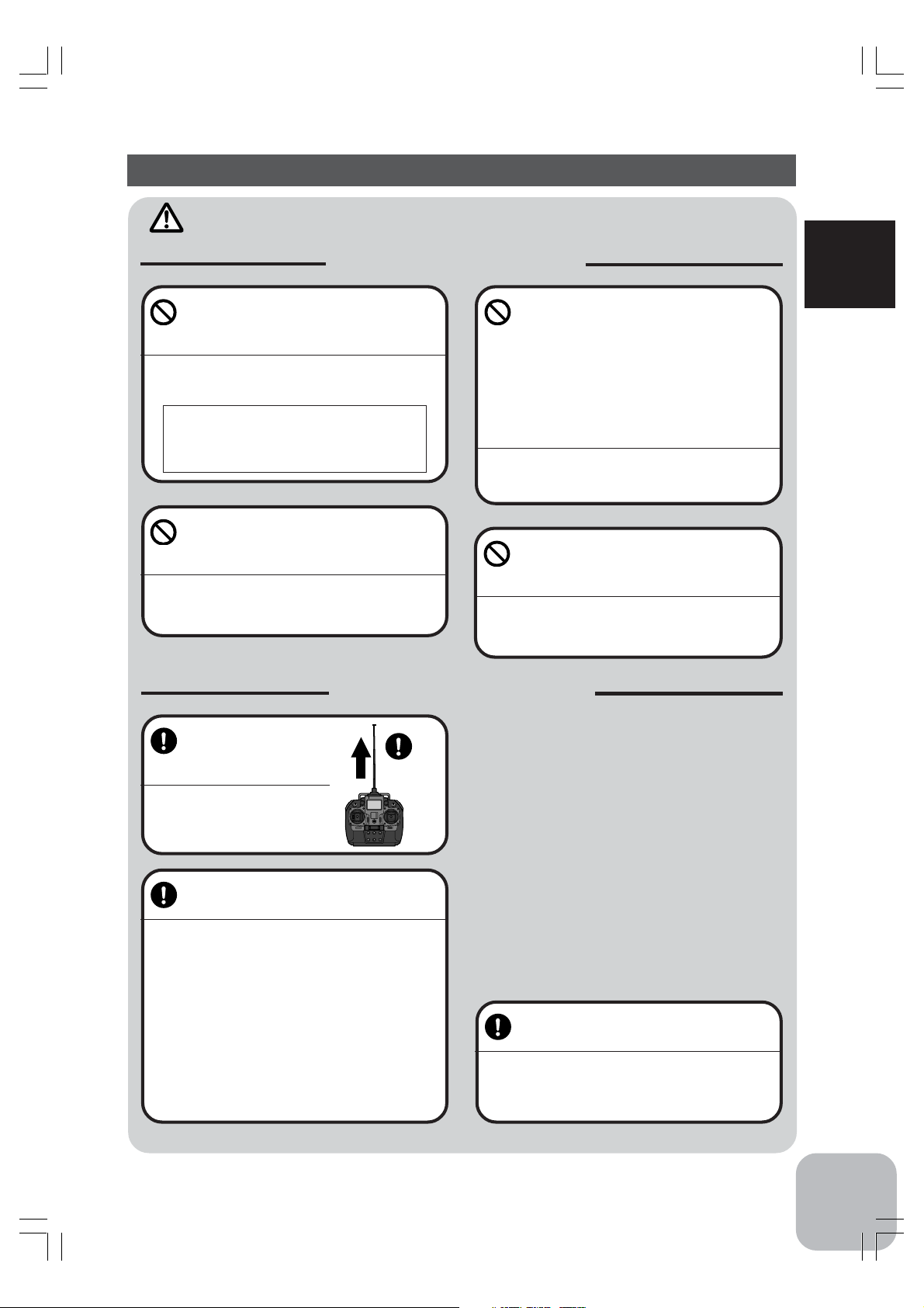
Extend the transmitter antenna to its full
length.
If the transmitter antenna is not
fully extended the operating
range of the radio will be reduced.
Full
Length
Do not operate in the following
places.
-Near other sites where other radio control
activity may occur.
-Near people or roads.
-On any pond when rowboats are present.
-Near high tension power lines or communication broadcasting antennas.
Interference could cause loss of control . Improper installation of your Radio Control System in your model
could result in serious injury.
Do not operate this R/C system when
you are tired, not feeling well or under
the influence of alcohol or drugs.
Your judgment is impaired and could result in a dangerous situation that may cause serious injury to
yourself as well as others.
For Your Safety As Well As That Of Others
Always perform a operating range
check prior to use.
Problems with the radio control system as well as improper installation in a model could cause loss of control.
(Simple range test method)
Have a friend hold the model, or clamp it down or
place it where the wheels or prop can not come in
contact with any object. Walk away and check to
see if the servos follow the movement of the controls on the transmitter. Should you notice any abnormal operation, Do not operate the model. Also
check to be sure the model memory matches the
model in use.
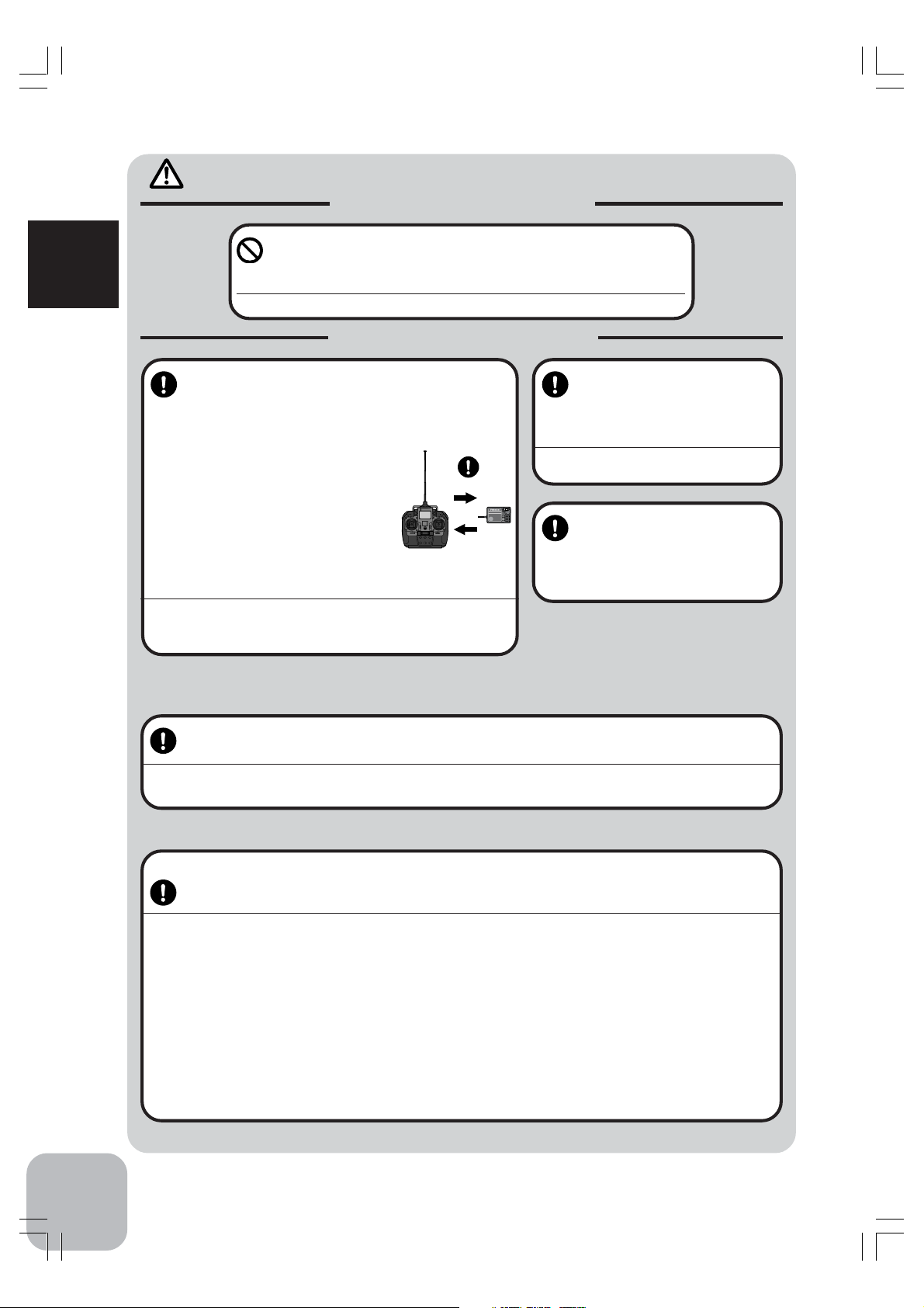
Check the transmitter antenna to be
sure it is not loose.
If the transmitter antenna works loose, or is disconnected while the model is running signal transmission
will be lost. This will cause you to lose control of the
model..
7
Page 7
Caution
Prohibited Procedures
Do not touch the engine, motor, speed control or any part of
the model that will generate heat while the model is operating
or immediately after its use.
For Your Safety As Well As That Of Others
These parts may be very hot and can cause serious burns.
Mandatory Procedures
Turning on the power switches.
Always check the throttle trigger on the
transmitter to be sure it is at the neutral
position.
1. Turn on the transmitter power switch.
2. Turn on the receiver or speed control
power switch.
Turning off the power switches
Always be sure the engine is not
running or the motor is stopped.
1. Turn off the receiver or speed control power switch.
2. Then turn off the transmitter power switch.
If the power switches are turned off in the opposite
order the model may unexpectedly run out of control
and cause a very dangerous situation.
ON
OFF
FP-R113F
FM
1
2
3
B/C
When making adjustments to
the model do so with the engine not running or the motor
disconnected.
You may unexpectedly lose control and
create a dangerous situation.
When operating your model
always display a frequency
flag on your transmitter antenna.
When adjusting the transmitter on land while preparing to run (cruise), take measures
so that the wind will not knock over the transmitter.
If the transmitter is knocked over, the throttle stick may be accidentally set to the operating position and you may
lose control.
8
(Fail safe function) ---H.R.S or PCM mode only
Before running (cruising), check the fail safe function.
Check Method;
Before starting the engine, check the fail safe function as follows:
1) Turn on the transmitter and receiver power switches.
2) Wait at least one minute, then turn off the transmitter power switch. (The transmitter automatically transfers the fail
safe data to the receiver every minute.)
3) Check if the fail safe function moves the servos to the preset position when reception fails.
The fail safe function is a safety feature that minimizes set damage by moving the servos to a preset position when
reception fails. However, if set to a dangerous position, it has the opposite effect. When the reverse function was used
to change the operating direction of a servo, the fail safe function must be reset.
Setting example: Throttle idle or brake position
Page 8
Nicad Battery Handling Precautions
(Only when Nicad batteries are used)
Warning
Mandatory Procedures
Always check to be sure your batteries have been charged prior to operating the model.
Should the battery go dead while the model is operating loss of control will occur and create a very dangerous situation.
When the model is not being used,
always remove or disconnect the
Nicad battery .
Should the battery be left connected this could create
a dangerous situation if someone accidentally turns
on the receiver power switch. Loss of control would
occur.
Caution
Prohibited Items
Do not use commercial AA
size Nicad batteries.
Quick charging may cause the
battery contacts to overheat and
damage the battery holder.
Use
prohibited
Nicad AA size
batteries.
To recharge the transmitter Nicad ,
use the special charger made for this
purpose.
Overcharging could cause the Nicad battery to overheat, leak or explode. This may lead to fire, burns,
loss of sight and many other type's of injuries.
Special
Charger
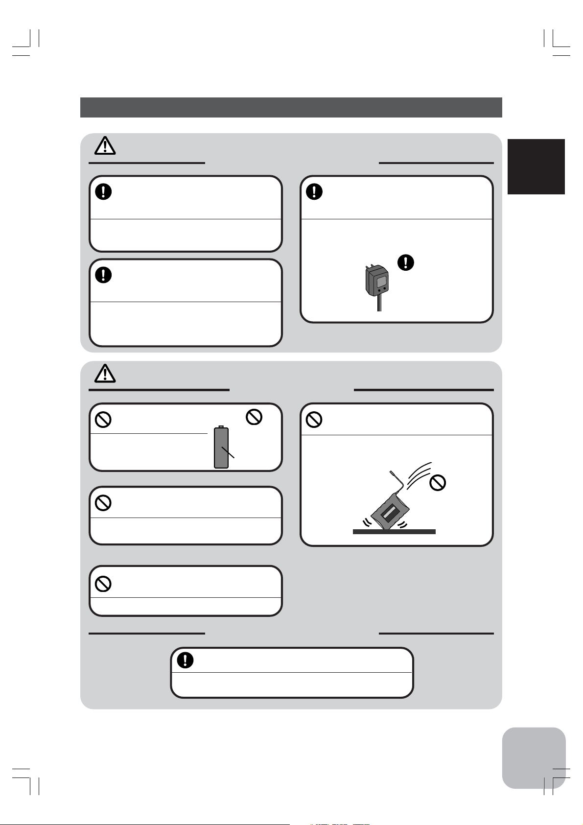
Do not drop the Nicad battery or expose it to strong shocks or vibrations.
The battery may short circuit and overheat, electrolyte
may leak out and cause burns or chemical damage.
For Your Safety As Well As That Of Others
Do not short circuit the Nicad battery
terminals.
Causing a short circuit across the battery terminals
may cause abnormal heating, fire and burns.
Never insert or remove the charger
while your hands are wet.
You may get an electric shock.
Mandatory Procedures
Always keep the charger disconnected from the
outlet while it is not in use.
It is important to prevent from unexpected accidents such as abnormal heat generation.
Shock
Prohibited
9
Page 9
Storage and Disposal Precautions
Warning
Prohibited Procedures
Do not leave the radio system or
For Your Safety As Well As That Of Others
models within the reach of small children.
A small child may accidentally operate the system,
this could cause a dangerous situation and injuries.
Nicad batteries can be very dangerous when mishandled and cause chemical damage.
Do not throw Nicad batteries into a
fire. Do not expose Nicad batteries to
extreme heat. Also do not disassemble or modify a Nicad battery
pack.
Overheating and breakage will cause the electrolyte
to leak from the cells and cause skin burns, loss of
sight as well as other injuries.
<Nicad Battery Electrolyte>
The electrolyte in Nicad batteries is a strong alkali. Should you get even the
smallest amount of the electrolyte in your eyes, DO NOT RUB, wash immediately with water, seek medical attention at once. The electrolyte can cause blindness. If electrolyte comes in contact with your skin or clothes, wash with water
immediately.
Mandatory Procedures
When the system will not be used for
any length of time store the system
with batteries in a discharged state.
Be sure to recharge the batteries prior
to the next time the system is used.
If the batteries are repeatedly recharged in a slightly
discharged state the memory effect of the nicad battery may considerably reduce the capacity . A reduction in operating time will occur even when the batteries are charged for the recommended time.
10
Caution
Prohibited Procedures
Do not store your R/C system in the
following places.
- Where it is extremely hot or cold.
- Where the system will be exposed to direct
sunlight.
- Where the humidity is high.
-Where vibration is prevalent.
-Where dust is prevalent.
-Where the system would be exposed to
steam and condensation.
Storing your R/C system under adverse conditions
could cause deformation and numerous problems
with opreation.
<Nicad Battery Recycling>
A used Nicad battery is valuable resource. Insulate the battery terminals and
dispose the battery by taking it to a battery recycling center.
Mandatory Procedure
If the system will not be used for a
long period of time remove the batteries from the transmitter and model
and store in a cool dry place.
If the batteries are left in the transmitter electrolyte
may leak and damage the transmitter. This applies to
the model also, remove the batteries from it also to
prevent damage.
Page 10
Other Precautions
Caution
Prohibited Procedures
Do not expose plastic parts to fuel,
motor spray, waste oil or exhaust.
The fuel, motor spray, waste oil and exhaust will penetrate and damage the plastic.
Mandatory Procedures
Always use only genuine Futaba
transmitters, receivers, servos, FET
amps (electronic speed
controls),Nicad batteries and other
optional accessories.
Futaba will not be responsible for problems caused by
the use of other than Futaba genuine parts. Use the
parts specified in the instruction manual and catalog.
Caution
Prohibited Procedures
Never use any RF module other than the RF module specially designed for the 3VCS.
Futaba will not be responsible for any problems caused by the use of non-Futaba parts or equipment in conjunction with this radio system. Please use parts and equipment that are listed in this instruction manual alone. There
is no compatibility between module TZ-FM module for T3VCS and TU-FM module for T3VC. Even if those modules were used mistakenly, the performance would be very poor and the control area would become narrow,
causing out-of-control.
For Your Safety As Well As That Of Others
11
Page 11

- High Response System (H.R.S. system)
When used with the H.R.S. system, a speed of triple that of an FM system at average
response is realized. (Comparison with other Futaba products) The T3VCS transmitter is compatible with the H.R.S. system, PCM1024 system, and PPM (FM) system.
- 110x64 dot large graphic LCD/with backlighting
EXP curve, throttle curve, servo view, and other graph display and function selection
can batch display simple menus and function setup items, and data setup is easy.
Before Using
Backlighting that can be turned ON/OFF also improves recognition at indoor circuits,
etc.
- 10 models memory/+ 10 models by using a data pack
Model names can use up to 10 letters, numbers, and symbols so that easily understood
names can be set. Model copy function simplifies creation of a model memory with
different fine setups. An additional 10 models memory can be added by using the
optional CAMPac-16K.
Before Using
Features
- Two function selection modes: Menu selection and direct call
Setup screens are called from a menu screen. The menu screen can be selected from
among 3 levels (LV1/LV2/LV3) to match the level of use.
Frequently used (high urgency) functions can be quickly called by assigning them to
direct call buttons. (6 functions)
- Brake mixing for large cars (BRAKE-MIX)
Brake mixing of the front and rear wheels of 1/5GP cars, etc. has delay and balance
adjustment functions.
- Second dual rate (2ND D/R)
Steering angle can be switched with one touch while running.
- Anti-skid Braking System (A.B.S.)
This function applies the brakes so that the tires of gasoline engine cars, etc. do not
lose their grip on the road even when braking at corners.
- Throttle acceleration (TH-ACCEL)
Gasoline engine cars have a time lag before the clutch and brakes are connected. The
TH-ACCEL function minimizes this time lag.
- Throttle speed (TH-SPEED)
Sudden trigger operation on slippery roads only spins the wheels unreasonably and
does not accelerate smoothly. Setup the throttle speed function allows smooth and
enjoyable operation while at the same time reducing battery consumption.
12
Page 12

- Start function (AT-START)
When the throttle trigger is set to full throttle simultaneously with starting on slippery
roads, the wheels spin and the vehicle does not accelerate (start). Setup the start
function allows smooth starting.
- Steering speed (ST-SPEED)
"When you sense that the steering servo is too fast, etc., the servo operating speed
(direction that suppresses the maximum speed) can be adjusted.
- Racing timer (TIMER)
A lap timer can record 99 lap times and the total time. The timer can also be started
automatically by trigger operation. The race time and an audible alarm can be set. A
navigation timer effective during training runs is provided. Target lap and refueling
time can be indicated by audible alarm. Other timers are an up timer and a down
timer.
- Digital trim
The trim position is constantly displayed on an LCD screen. The operation amount of
1 step can also be adjusted. Steering and throttle trim operations have no effect on the
maximum steering position.
- Function select dial function (FUNC-DIAL)
This function assigns a function to trimmers (digital trim, button trim, knob). The
step size and operating direction can also be adjusted. Trim positioning at each model
call is unnecessary because all the dials are digital.
Before Using
- Function select switch function (FUNC-SW)
This function assigns functions to the two installed switches. The operating direction
can also be set.
- Black antenna
- Tension adjustment function
Stick tension can be adjusted from the outside.
- Adjustable Throttle Stick Travel (Mechanical ATL)
- Display switch
Functions can be set without emitting radio waves.
- Receiver w/DSC is standard equipment (Connection cord is option.)
HRS system: R203HF, PCMN type: R113iP
- 7-color LED pilot lamp
You can select your favorite color.
13
Page 13
Set Contents
After opening the box, first check if the contents conform to the following. The contents depend on the set as shown below.
Transmitter T3VCS
RF module
Receiver R203HF(HRS-FM) or R113iP(PCM)
Before Using
Miscellaneous
- If any of the set contents are missing, or you have any questions, please contact your
dealer.
Caution
Never use any RF module other than the RF module specially designed for the 3VCS.
Futaba will not be responsible for any problems caused by the use of non-Futaba parts or equipment in conjunction with this radio system. Please use parts and equipment that are listed in this instruction manual alone. There
is no compatibility between module TZ-FM module for T3VCS and TU-FM module for T3VC. Even if those modules were used mistakenly, the performance would be very poor and the control area would become narrow,
causing out-of-control.
TZ-FM
*Installed in transmitter.
Transmitter Ni-cad battery pack NT8F700B
or Battery box
*Installed in transmitter.
Receiver switch
Instruction manual
Prohibited Procedures
14
Caution
In case of the High Response System (H.R.S) receiver R203HF, always use only under
the following conditions:
Servo; 6V type Digital Servo only
Power supply; 6V Nicd battery
Transmitter setting; "HRS" mode
If the conditions are different, control is impossible.
And Fail Safe Unit (FSU1) is not available.
Caution
Always use only genuine Futaba transmitter, receiver, FET amp, Ni-cad battery and
other optional parts.
Futaba will not be responsible for damage caused by other than genuine Futaba parts and components. Use only
the genuine Futaba parts and components listed in the instruction manual and catalog.
Page 14
Nomenclature
Transmitter T3VCS
CH3 knob (KNOB)
Switch(SW2)
(See page 19 for
the adjustment
instructions.)
Mechanical
ATL
adjusting
screw
(See page 18 for
the adjustment
instructions.)
Neutral
adjusting
Pilot lamp
Antenna
LCD screen
Carryng bar
Display switch
(DSP)
(See page 23 for the operating instructions.)
Switch(SW1)
Power
switch
Before Using
(See page 17 for the operating instructions.)
Digital trim 3
(DT3)
Hook
Steering stick
Throttle stick
Steering trim (DT1)
Throttle trim (DT2)
(See page 17 for the operating
instructions.)
Edit buttons
CAMPac
insertion
hole
(See page 22 for the operating instructions.)
(See page 17 for the operating
instructions.)
*The switches, knobs, and trimmers in the figure are shown in the initial setting position.
Precautions when turning the power switch on and off.
When the data was changed using the edit keys or trim levers, wait at least two seconds before turning off the power. If the power is turned off within two seconds after
the data was changed, the new data will not be written to memory.
Stick lever head the precautions
There is a small projection at the tip of the lever heads to prevent slipping. When
carrying the transmitter, be careful these projections do not damage your skin,
clothes, or other objects.
15
Page 15
(See page 22 for the handling instructions.)
Before Using
RF module
TZ-FM
RF.MODULE
FOR
TRANSMITTER
PHONE
- Use a commercial earphone.
(Use A radio earphone with a 3.5mm diameter plug.)
- When the surroundings are noisy during races, etc.,
you can listen to the alarm tone using an earphone.
The alarm tone can also be heard from the transmitter.,
Sound port
Grip
- When you want to adjust the steering stick spring tension, remove this
grip. (See page 19 for the adjustment instructions.)
ATL button trim
(BT2/ATL)
Battery cover
Grip
- When you want to adjust the
throttle stick spring tension, remove
this grip. (See page 19 for the adjustment instructions.)
Steering D/R button
(BT1/D/R)
Charging jack
(See page 20 for the
charging instructions.)
16
DSC jack
- The DSC cord sold separately is necessary.
(See page 104 for the usage instructions.)
Page 16
Digital Trim Operation
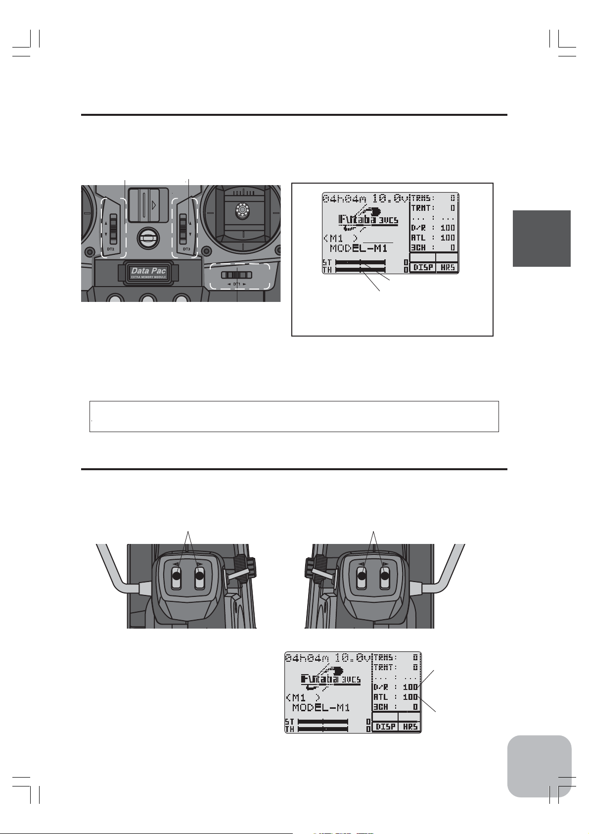
(Initial settings: DT1: Steering trim, DT2: Throttle trim, DT3: -------)
Push the lever in the arrow direction (up/down or right/left). The current position is
displayed on the LCD screen.
DT2
- Each step is indicated by a tone.
-When the trim exceeds the maximum trim adjustment range, the tone will change pitch and the lever
will not move any farther.
DT3
DT1
Steering trim display
Throttle trim display
(*1) For a description of how to display steering
EXP on the LCD screen, see page 99.
Trim Operation
With the center trim feature, trim adjustments have no effect on the maximum servo
travel. This prevents the linkages from binding when adjustments are made.
Button Trim Operation
(Initial state: BT1; Steering D/R, BT2; ATL)
Operate by pressing the button of the direction you want to set. The current set value
is displayed on the LCD screen.
Before Using
BT2
ATL
- Each step is indicated by a tone.
- When the dial reaches the maximum or
minimum adjustment range, the tone will
change pitch and the dial cannot turn farther.
- When both buttons are pressed simultaneously for about one second, the set value
returns to the initial value.
BT1BT2
BT1
D/R
Steering D/R display
ATL display
17
Page 17
2DT2
Neutral Adjuster Operation
The neutral adjuster selects the throttle stick neutral position.
- (High side):(brake/back side): 5:5 or 7:3 can be selected.
Setting
Switch to the side that uses the neutral
adjuster lever.
-This function only changes the throttle stick neutral position; it has no effect on the servo neutral
position.
Before Using
Stick Lever Head Adjustment
The length of the lever head of the steering and throttle sticks can be adjusted.
Adjustment
1. Unlock lever head “A” by turning it counterclockwise.
2. Adjust the head to the length best for
you, then lock the heads by turning lever
head “A” clockwise and lever head “B”
counterclockwise.
5:5
7:3
Neutral adjuster
Lever head
“B”
1
2
DT
Lever head
“A”
18
- When you want a long lever head, use the stick
adapter (sold separately).
Stick Mounting Angle Adjustment
The mounting angle of the throttle and steering sticks can be adjusted.
- The mounting angle can be adjusted approximately 5 degrees.
Setting
1. Loosen the four set screws.
2. Change the stick angle.
3. Retighten the four set screws.
- The figure at the right shows the throttle stick.
The steering stick can be adjusted similarly.
Set
screws
5 degrees
Page 18

2
Mechanical ATL Adjustment
Make this adjustment when you want to make the throttle stick brake (back) or high
side stroke narrower.
Adjustment
Brake (back) side
Brake (back) side adjustment
Make this adjustment by turning the adjusting
screw above the stick with a Phillips screwdriver.
High side adjustment
Make this adjustment by turning the adjusting
screw below the stick with a Phillips screwdriver.
- When the adjusting screw is turned counter clockwise,
the stroke becomes narrower.
High side
Caution
When the stroke was adjusted, the throttle servo travel must be adjusted by data setting. If the stroke is made too narrow, the adjusting screw may fall out.
Stick Tension Adjustment
Make this adjustment when you want to change the steering stick or throttle stick
spring tension.
DT
Before Using
Adjustment
1. Remove the grip on the back of the
transmitter.
2. Turn the screw inside the adjusting
hole using a small Phillips screwdriver such as a watchmaker’s
Steering side
screwdriver.
- Turning the adjusting screw clockwise,
increases the spring tension.
- The adjustment range is about five
turns in both directions, from the initial
position.
Grip
:Tension adjusting screw position
:Grip mounting hole (left and right 6 points each)
Caution
If turned too far counterclockwise, the adjusting screw may fall out.
PHONE
Throttle side
Grip
19
Page 19
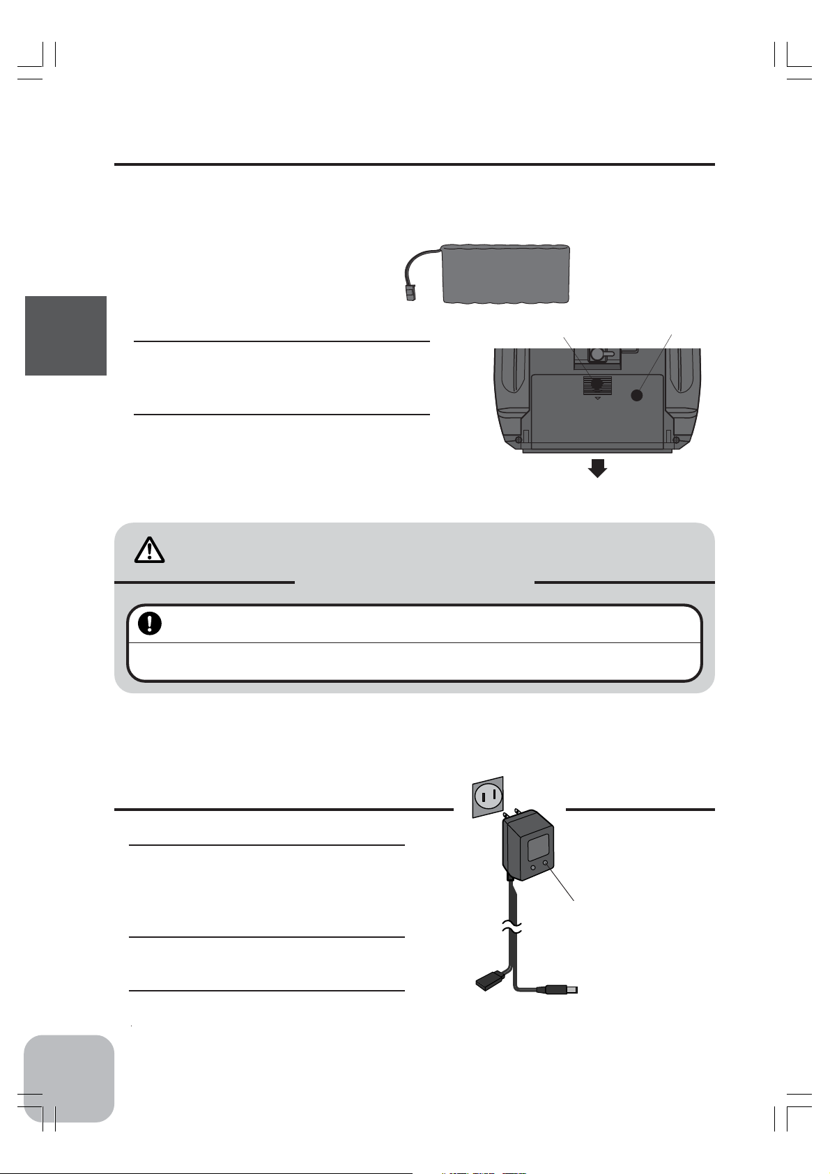
Ni-cad Battery Replacement
The Ni-cad battery is connected by a connector so that it can be removed when you
will not be using the transmitter for a long time, or when replacing a dead battery with
a spare battery.
- Always use an NT8F7000B Ni-cad battery.
Ni-cad battery
NT8F700B
Removal
1. Slide the transmitter battery cover
Before Using
in the arrow direction while pressing the part shown in the figure.
2. Remove the Ni-cad battery and disconnect the connector.
Caution
Pay full attention so that the battery cover wouldn't pinch the cable of the Ni-cad
battery.
Pinching the cable by the battery cover can lead to an electrical shortage, fire and abnormal heat generation,
which may cause burns and fire disaster.
- While pressing here
Mandatory Procedures
Battery cover
PHONE
20
Charging the Ni-cad Battery
Charging
1. Plug the transmitter cord of the
special charger into the charging jack on the rear of the transmitter.
2. Plug the charger into an AC outlet.
3. Check that the charging LED
lights.
AC outlet
Charger
Transmitter charging
LED
Cord to transmitter
charging jack
Page 20
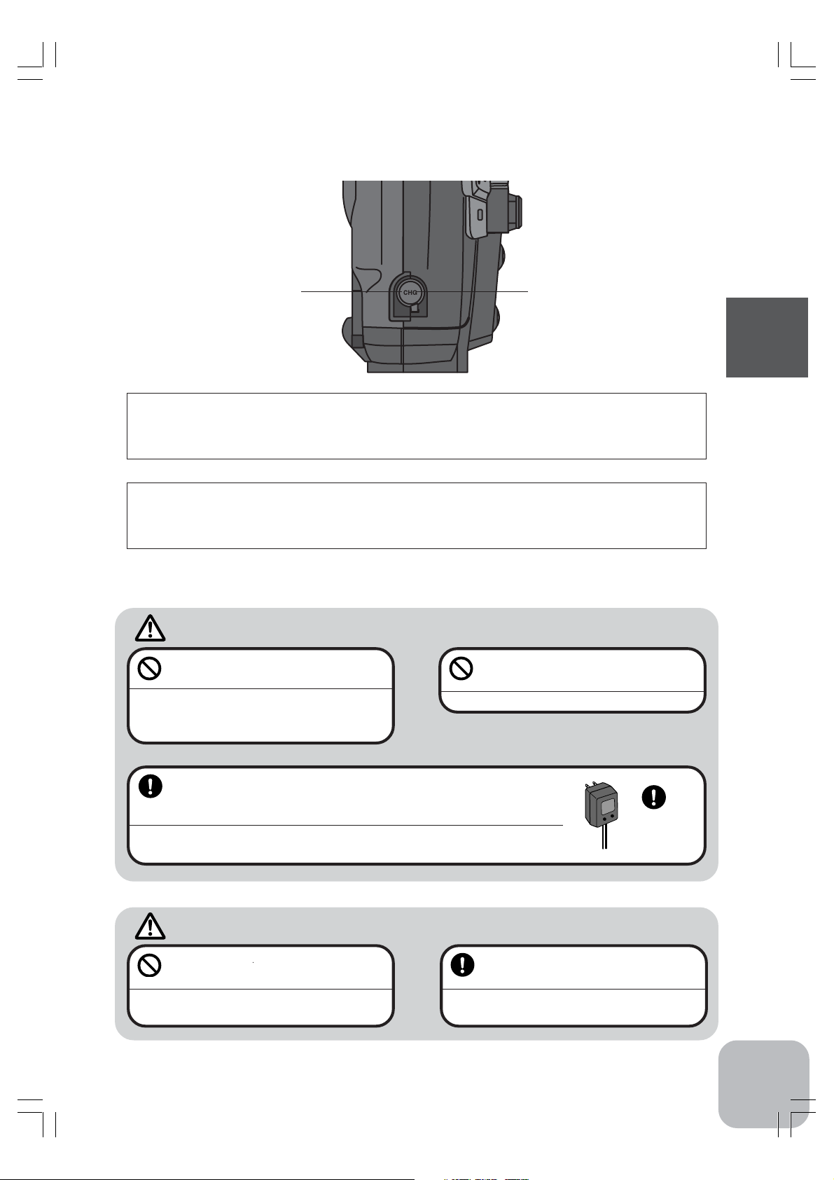
Charging jackCover
When charging the NT8F700B Ni-cad battery with the special charger, allow about
15 hours for charging. If the transmitter has not been used for some time, cycle the
battery by charging and discharging it two or three times.
Over current protection
The transmitter charging circuit is equipped with an over current protection circuits
(1.5A). If the battery is charged with a quick charger for other than digital proportional R/C sets, it may not be fully charged.
Warning
Never plug it into an outlet other
than indicated voltage.
Plugging the charger into the wrong outlet may result in an explosion, sparking, or fire.
Always use the special charger or a quick charger for digital proportional R/C sets to charge a digital proportional R/C set Ni-cad
battery.
Overcharging a Ni-cad battery can result in burns, fire, injuries, or loss of sight due to
overheating, breakage, or electrolyte leakage.
Do not insert and remove the
charger when you hands are wet.
It may cause an electric shock.
Use the
special
charger.
Before Using
Caution
Never try to recharge a dry cell battery.
The transmitter may be damaged or the battery
electrolyte may leak or the battery may break.
When the charger is not in use, disconnect it from the AC outlet.
Do this to prevent accidents and to avoid overheating.
21
Page 21
RF Module
Removal
1. Pull the RF module forward while
pressing the tabs at the top and
bottom inward.
Insertion
1. Insert the RF module while being
careful not to bend the transmitter
side connector pins.
2. Insert the RF module until the tabs
Before Using
at the top and bottom snap in place
with a “click”.
RF Module Temperature Rise
The temperature of the RF module will rise slightly during operation.
Data Backup
The data (transmitter and Data Pac) of each function of the 3VCS transmitter is
stored in a memory element that does not require backup battery. Therefore, the
transmitter can be used without paying attention to the life of the backup battery. The
set data is not lost even when the transmitter battery is changed.
TZ-FM
RF.MODULE
FOR
TRANSMITTER
PHONE
RF module
Tabs
22
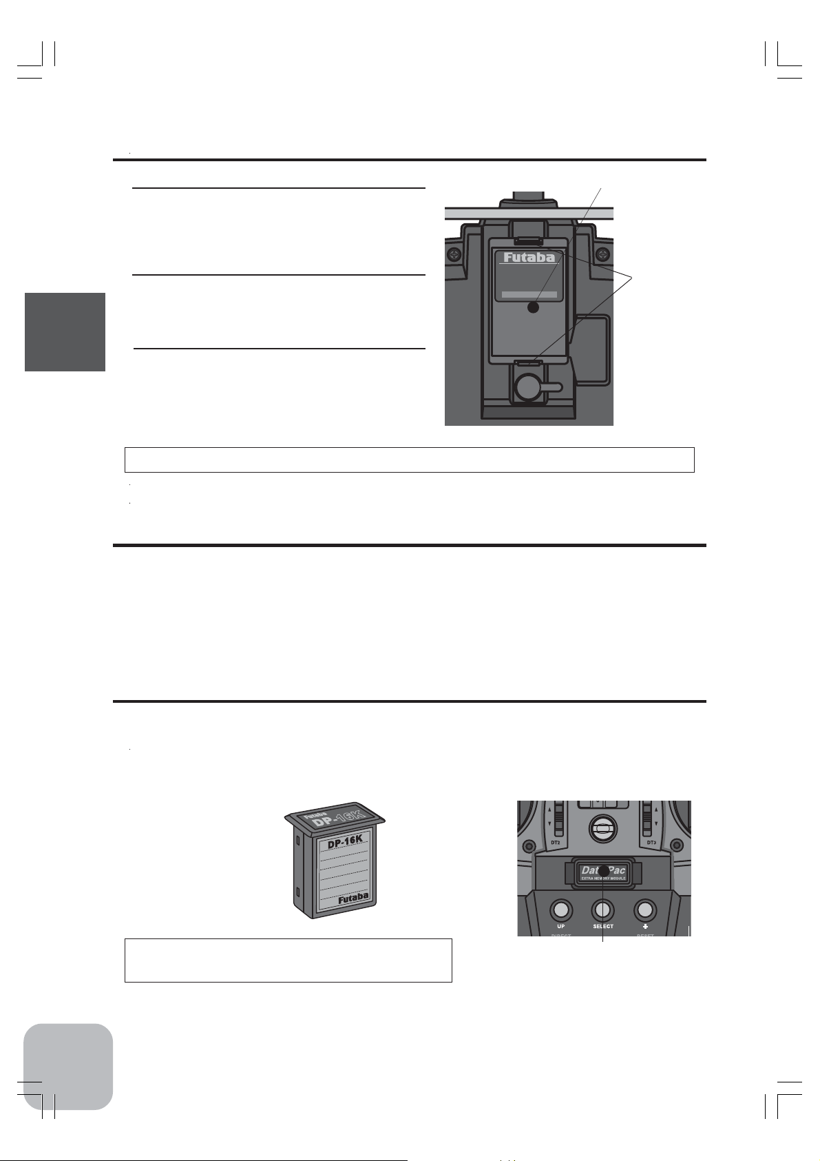
Handling the CAMPac-16K / Data Pac DP-16K
The data for ten models can be stored in the transmitter memory and the data for
ten more models can be stored in the removable CAMPac-16K (optional).
Do not use any removable memories other than CAMPac-16K
CAMPac-16K
(Optional)
Removal Precautions
Always turn off the transmitter power before
installing and removing the CAMPac-16K.
CAMPac slot
Page 22
When inserting and removing the data pack
Always turn off the transmitter power before removing or inserting the data pack.
Data pack initialization
When using the data pack, initialization is necessary so
that the data pack can be used with this transmitter. When
"INITIALIZE?" is displayed on the screen at power ON,
press the (+) button. This automatically initializes the data
MEMORY MODULE
INITIALIZE ?
YES > +
NO > -
pack. No further action is necessary.
When a data pack used with another model has been inserted, and initialization is
executed by pressing the (+) button when "INITIALIZE?" is displayed on the screen
at power ON, the old data is destroyed so the data pack can be used with the 3VCS.
Data interchangeability with other models
Data is not interchangeable with 3PK, 3VC, and other transmitters other than the
3VCS.
Set data backup
The set data of each function (transmitter body and data pack) of the 3VCS transmitter is stored in a memory element that does not require a backup battery. Therefore,
the 3VCS transmitter can be used without paying attention to the backup battery life.
Before Using
Display switch
If the display switch is turned on without turning on the power switch, transmitter
side data setup is possible without emitting radio waves.
Display switch
ON
Warning
OFF
Never turn on the power switch while
this function is in use.
If the power switch is turned on, radio waves will be
emitted and interfere with
vehicles (boats) operating on the same band (frequency) and is very dangerous.
23
Page 23
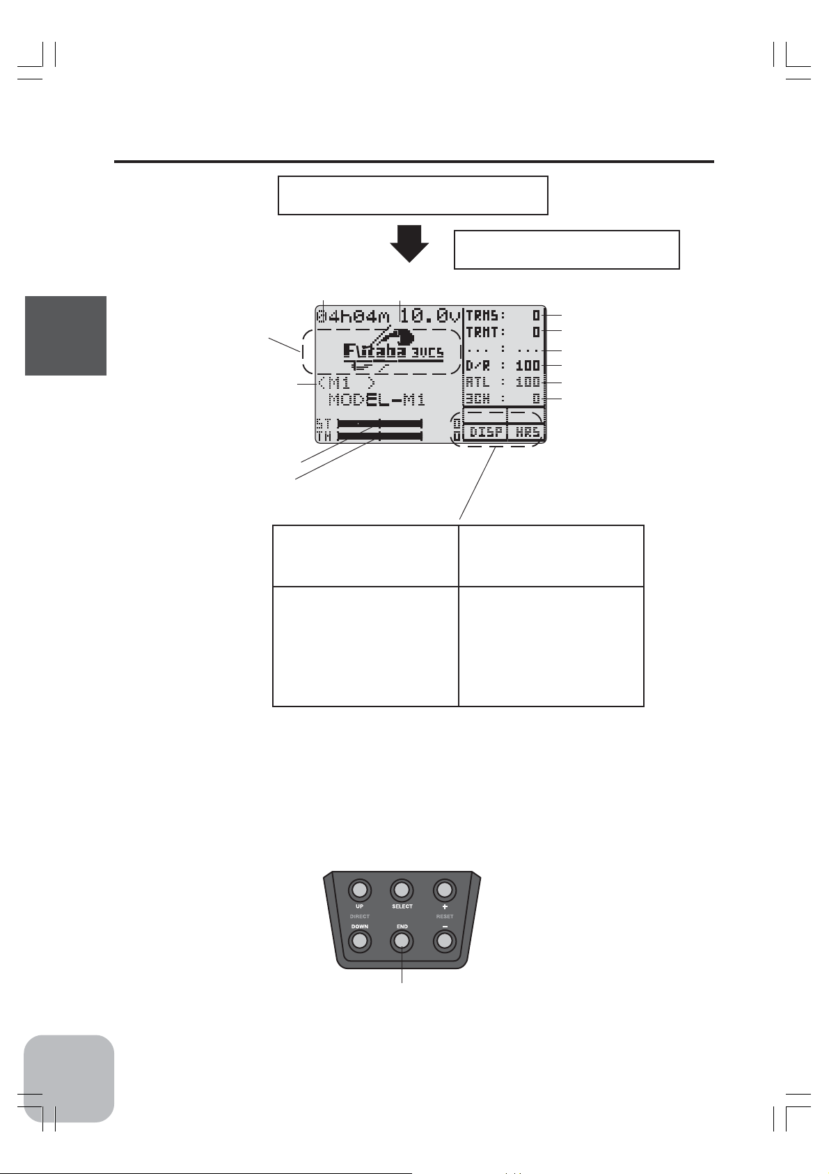
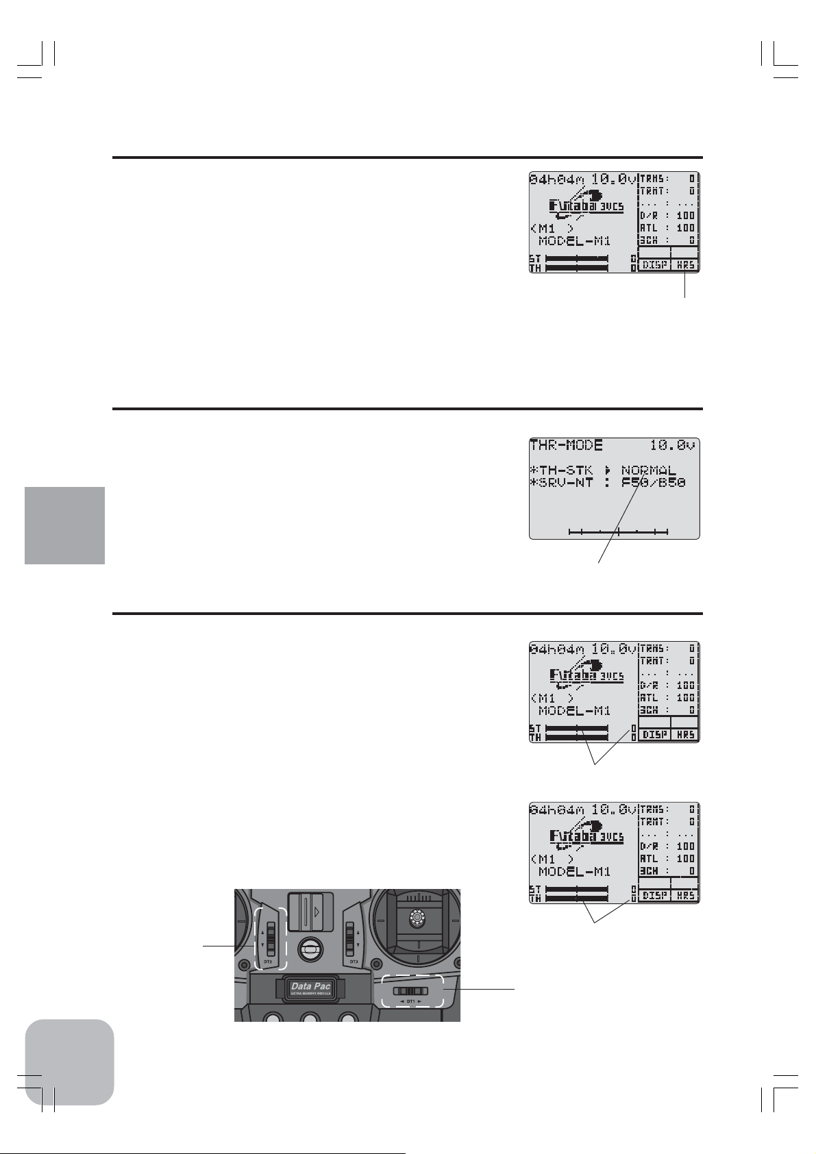
Display when power switch turned on
Power switch turned on
Beep confirmation sound is generated and
the initial screen shown below appears.
* Display mode can be changed
by using the SYSTEM function.
(See pge 92)
Before Using
Model name (10 characters)
Steering trim display
Throttle trim display
Total timer display (H:M)
* Displays whether or not a data
pack is inserted. When a data pack
is inserted, "DPAC" is displayed.
* When radio waves are being emitted, "RF" is displayed. When radio
waves are
not being emitted when turned on by
display switch and when the DSC
function is used, "DISP" is displayed.
Battery voltage display
* "BLHT" is displayed when backlighting is ON.
* The current operation mode is displayed. ("PPM"/"PCM"/"HRS")
DT1
DT2
DT3
BT1
BT2
KNOB
* Function names and rate
assigned to dials are displayed.
24
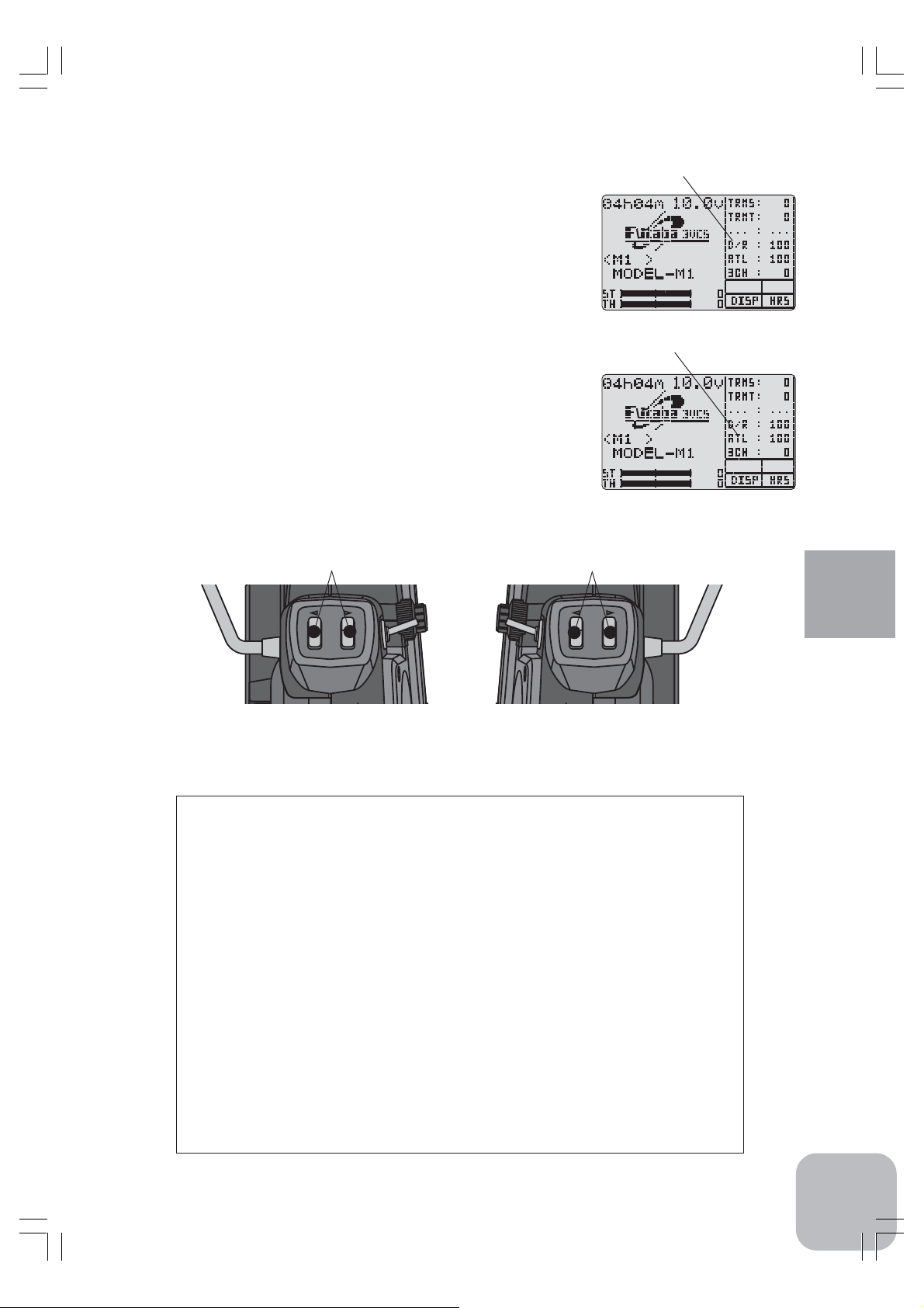
User name display
When the (END) button is held down for 1 second or longer at the initial screen, the
Futaba logo and user name are displayed for about 2 seconds.
(END) button
Page 24
Total timer
The total timer shows the accumulated time from last reset.
The total time does not change even when the model changes.
Reset method
1 In the initial screen state, hold down the (+) and (-) buttons simultaneously
for 1 second.
* The total timer display counts up from 1 minute to 99hours 59 minutes.
(+) buttons
(-) buttons
LCD Screen Contrast
The LCD screen contrast can be adjusted. (For more information, see page .)
Caution
Do not adjust the contrast so that the LCD is too bright or too dark.
When the display cannot be read due to a temperature change, data cannot be set.
LCD Screen Temperature Change
In the following cases, the LCD may become difficult to read due to a temperature
change.
- On hot summer days and cold winter days, the LCD may be easy to read indoors, but difficult to
read outdoors.
- If the contrast is too bright or too dark, temperature changes and lighting conditions may cause the
screen to become difficult to read.
Contrast adjustment when not called
1 Turn on the transmitter power again.
2 When the screen is too dark or too bright, adjust to a suitable contrast by pressing
the (-) or (+) button, respectively, while pressing the (SEL) button.
Before Using
(SEL) button
(+) buttons
(-) buttons
25
Page 25
Nomenclature
Antenna
Before Using
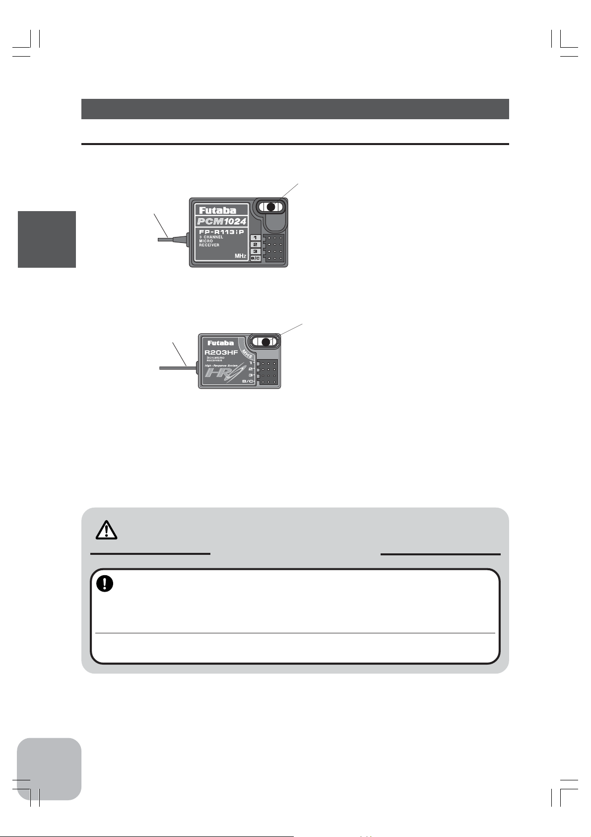
R113iP
receiver
Receiver
Crystal
When changing the frequency, use the
specified Futaba crystal set.
Connectors
1: Steering servo (CH1)
2: Throttle servo (CH2)
3: CH3 servo (CH3)
B/C: Power connector/DSC connector
Antenna
When changing the frequency, use the
specified Futaba crystal set.
Connectors
Crystal
1: Steering servo (CH1)
R203HF
receiver
2: Throttle servo (CH2)
3: CH3 servo (CH3)
B/C: Power connector/DSC connector
For the receiver, servos, and other connections, see page 27. For the DSC cord (option) connections, see page 104.
Caution
Mandatory Procedures
In case of the High Response System (H.R.S) receiver R203HF, always use only the
following conditions:
Servo; 6V type Digital Servo only
Power supply; 6V Nicd battery
Transmitter setting; "HRS" mode
If the conditions are different, control is impossible.
And Fail Safe Unit (FSU1) is not available.
26
Page 26
Installation
Receiver and Servo Connections
When connecting and installing the receiver and servos, read the “Installation Safety
Precautions” on the next page.
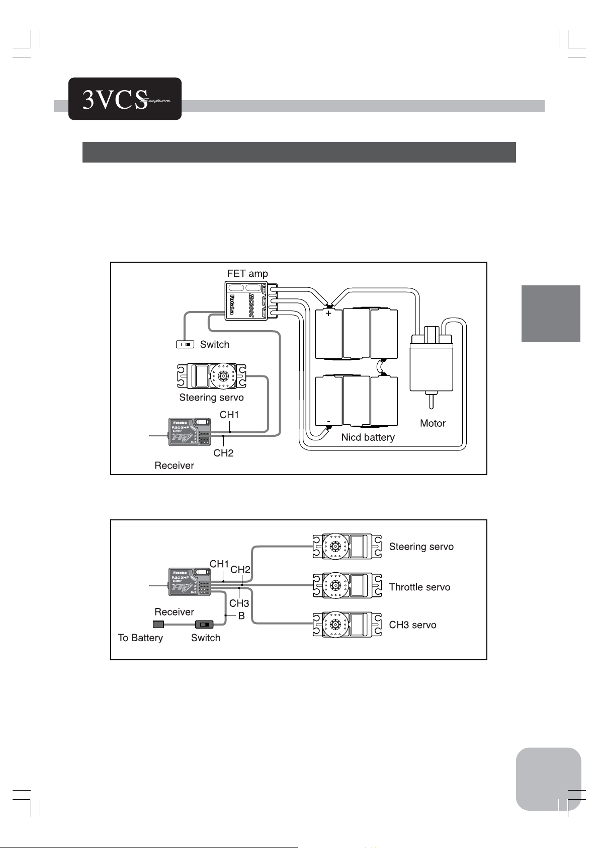
Installation When An FET Amp Is Used (MC800CFET Amp)
Installation For Gas Powered Models
Installation
27
Page 27
Installation Safety Precautions
Warning
Connector Connections
Be sure the receiver, servo, crystal
and connectors are fully and firmly
connected.
If vibration from the model cause a connector to
work loose while the model is in operation, you may
lose control .
Receiver Vibration Damping and
Waterproofing
(Car)
Dampen the vibration to the receiver
by mounting to the chassis or mounting plate with thick double sided tape
Installation
in electric powered models. In gas
powered models wrap the receiver in
foam and mount it where the vibration
is the least prevalent.
(Boat)
Dampen the vibration to the receiver
by wrapping it in foam. Waterproof by
placing it in plastic bag or watertight
radio box in model.
If the receiver is subjected to strong vibration or shock
erratic or loss of control may occur. If any moisture
comes in contact the receiver and servos you may
expertise the same result as well as damage to the
system.
Electronic speed control
Install the heat sinks where they will
not come in contact with aluminum,
carbon fiber or other parts that conduct electricity.
If the FET Amp (Electronic speed control) heat sinks
touch other materials that conduct electricity a short
circuit could occur. This could result in loss of control
and damage to the system.
Servo Throw
Operate each servo over its full stroke
and be sure the linkage does not bind
or is loose.
The continuous application of unreasonable force to a
servo may cause damage and excessive battery
drain.
Servo Installation
When you install the servos always
use the rubber grommets provided in
servo hardware bags. Mount the servos so they do not directly come in
contact with the mount.
If the servo case comes in direct contact with the
mount vibration will be directly transmitted to the
servo.
If this condition continues for a long time the servo
may be damaged and control will be lost.
28
Receiver Antenna
Do not cut or bundle the receiver antenna
Do not bundle the receiver antenna
together with the servo lead wires
Keep the receiver antenna at least 1
inch away from the motor and battery
and wires that handle heavy current
loads..
Cutting, bundling or routing the receiver antenna near
any devise that produce noise will reduce the operating range of the system and result in loss of control.
*Also route the receiver antenna away from metal,
carbon fiber and other parts that conduct electricity. These parts can transmit high frequency noise.
Motor Noise Suppression
Always install capacitors to suppress
noise when electric motors are used.
If capacitors are not properly installed you could experience erratic operation and reduced range as well as
loss of control.
Other Noise Suppression Methods
Be sure there are no metal parts in
your model which under vibration can
come in contact with other metal
parts.
Metal to metal contacts under vibration will omit a high
frequency noise that will effect the receivers performance. You could experience erratic operation and
reduced range as well as loss of control.
Page 28
Instal set-Up
Preparations (Transmitter)
Before setting the Transmitter functions, check and set items 1 to 4 below.
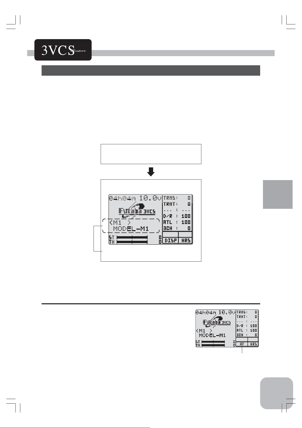
(Display when power switch turned on)
When the power seitch is turned on, the currently selected model number is dis-
played. Check of this number is model number you want to set-up. To change the
model number, use the Model Select function (See page75).
Turn on the transmitter power.
(Start screen)
The model number is displayed.
レバー類の準備
1.RF Output Check
If signals are output normally, RF output monitor "RF"
will be displayed on the screen.
If "RF" is not displayed, check if the transmitter crystal
and RF module are installed.
If the transmitter is abnoemal or faulty, contact your
Futaba dealer.
Initial Set-Up
"RF"
29
Page 29
2. Modulation Mode Check
The T3VCS transmitter output signal format can be
changed to match the type of receiver. Check if the modulation mode is set to match the receiver used.
When using an FM receiver (e.g., R133F), the modulation
mode must be set to "PPM". When using a PCM receiver
(e.g., R113iP), the modulation mode must be set to
"PCM". When using a H.R.S receiver (e.g., R203HF), the
modulation mode must be set to "HRS". If this setting is
incorrect, change it with the HRS/PCM/PPM Select (See
page 88) function.
3. Throttle Mode check
The T3VCS transmitter will automatically stop its braking
function of the throttle operation when the throttle stick is
replaced with the ratchet type for boat or other purposes.
In this case, set "BOAT" for "TH-STK" in the Throttle
Mode (See page 100). In case of using a ratchet type stick
"H.R.S"
for a car, it is possible to set the servo travel at 5:5 or 7:3
Initial Set-Up
upon your needs.
4. Trims Initial Set-Up
- Steering trim (DT1) check
At initial set-up, steering trim (Trim 1) is assigned to digital trim DT1 below the stick at the right side of the transmitter. Operate the DT1 lever and check if the steering
trim display on the screen changes. After checking the
trim, set the trim display to the center (N) position.
- Throttle trim (DT2) check
At initial set-up, throttle trim (Trim 2) is assigned to digital trim DT2 at the right side of the stick at the left side of
the transmitter. Operate the DT2 lever and check if the
throttle trim display on the screen changes. After checking
the trim, set the trim display to the center (N) position.
Throttle trim
(DT2)
Set "BOAT" in case
of the ratchet type.
Steering trim
Throttle trim
30
Steering trim
(DT1)
Page 30
- Steering dual rate (BT1) check
At initial set-up, steering dual rate (D/R) is assigned to
button trim BT1 at the right side of the transmitter.
Operate the BT1 button and check if the D/R value displayed on the screen changes. After checking ST.D/R,
set the steering dual rate to 100%. (Return to the initial
value (100% ) by pressing both buttons simultaneously
for about one second.)
- Throttle ATL (BT2) check
At initial setting, throttle ATL (ATL) is assigned to
button trim BT2 at the left side of the transmitter. Operate the BT2 button and check if the ATL value displayed on the screen changes. After checking TH.ATL,
set throttle ATL to 100%. (Return to the initial value
(100%) by pressing both buttons simultaneously for
about one second.)
Steering dual rate
Throttle ATL
BT1BT2
BT2
ATL
BT1
D/R
(Set-Up Procedure When Installed In a Car)
When installing the servos in a car, performing function set-up in the following order
is recommended.
1. Perform step 4. Trims Initial Set-Up of Preparations on the preceding page.
2. Set the servo direction of operation using the Reverse function.
(See page 72)
The servo installation method and linkage direction depends on the
kit. Therefore, the servo operation direction may have to be reversed relative to transmitter operation. Before installing the servo,
check the operating direction and set it using the Reverse function.
3. Set the subtrim and adjust the servo neutral point. (See page
71)
Initial Set-Up
4. Set the trigger travel by adjusting the throttle trigger mechanical
ATL to you liking.(See page 18)
5. Set EPA of each channel and adjust the servo throw (travel).
(See page 34)
31
Page 31

Function Map
Menu Selection
The function set-up screen can be easily selected from the function menu displayed
on the LCD screen.
The function menu can be selected from among the following 3 levels to match the
level of use. To select the level, use the Level Select function (See page 89).
-Level 3 (LV3): All functions can be selected. (For expert driver)
-Level 2 (LV2): For middle class driver
-Level 1 (LV1): Basic functions only
Function Menu Screen
(Start Screen)
In case of the LV3
Click or
button to
call the Function Menu
Screen.
Click button to return to
the Start
Function Map
Screen.
In case of the LV2
In case of the LV1
Click button to return
to the Function Menu
Screen.
The screen on the right shows
an example of MENU1 of LV3.
Click button to return
to the Function Select
Screen.
Click button to go to
the Function Select
Screen.
(Function Select Screen)
Clic or button to
select a function.
The reversely displayed item shows
the function currently selected.
Click to go to the
Function Set-up Screen.
(Function Set-up Screen)
32
The screen on the right
shows an example of setting EPA function.
Page 32

Direct Selection
The Direct Selection allows instant access to the six functions most frequently used.
The function set-up screen can be directly and quickly called with the special buttons
for each function of the six functions, they can be freely selected as the Direct Selection Button function.
INITIAL SETTING
Function
1. SUB-TRIM Subtrim
2. ST-EXP Steering EXP
3. MDL-SEL Model Serect
4. TH-EXP Throttle EXP
5. CHEPA Chanel End Point Adjuster
6. MDL-NAME Model Name
Push and buttons
simultaneously to call the
Direct Selection Screen.
(Initial Screen)
Upon your needs, select one of the
6 functions and then click its button
to call the Function Set-up Screen.
( Direct Selection Screen)
+
Click button to return
to the Start Screen.
(Function Set-up Screen)
The upper screen is an example of setting Throttle
EPA function.
Edit Buttons
In this instruction manual, Edit Buttons are represented by
the symbols shown below.
Function Map
33
Page 33

Functions
End point adjuster/EPA (All channels)
Use this when performing steering left and right steering angle adjustments, throttle
high side/brake side operation amount adjustment, and channel 3 servo up side/down
side operation amount adjustment during linkage.
- Correct the maximum steering angle and left and right steering angles when there is
a difference in the turning radius due to the characteristics, etc. of the vehicle.
Maximum steering angle
The EPA function basically determines the maximum steering angle of each channel.
The functions shown below may have been adjusted or the operating range set by
EPA function may be exceeded. Check the linkage each time the following functions
are adjusted.
- Sub trim (all channels)
- Program mixing slave side (all channels)
- Tilt mixing (steering, channel 3)
- Idle up (throttle)
- Throttle preset (throttle)
ATL trim
ATL trim allows adjustment of the brake side operation amount during operation.
Therefore, when the operating angle is adjusted with throttle EPA, ATL trim must
also be taken into account.
Remark
When the steering angle is insufficient even though EPA is increased to maximum
(120%), the steering angle can be increased somewhat by using program mixing.
(Setup example: See page 68.)
Functions
! Make sure that the knuckle stopper is not contacted during steering operation and that unreasonable force is not applied to the servo during
other channel operation.
If unreasonable force is applied to the servo horn at the knuckle stopper
during steering operation, the servo may malfunction and the model may
run out of control.
Warning
Caution!
Be sure that the
steering servo
does not howl.
Decide the EPA value at the
contact point.
34
End point adjuster/EPA (All channels)
Page 34

Calling the setup screen
* Calling from menu screen
(Initial screen)
Use the or
MENU
MENU SELECT
* When the direct call button is set,
the setup screen is also called by the
following method:
(Initial screen)
DIRECT SEL
button to select the
menu screen.
Press the button.
Use the or
button to select the
function.
Press the button.
Press the and
button simulataneously.
Press the button set
at this function.
Use the or button to
select the setup item.
* blinks at the current
setup item.
Steering (EPA) adjustment
(Preparation)
- Before setup the steering wheel steering angle, set the
steering D/R dial (initial setup: BT1) to the maximum
steering angle position 100%.
- Select setup item "ST-LFT" and make the following
adjustments:
Setup items
ST-LFT : Steering (left side)
ST-RGT : Steering (right side)
TH-FWD : Throttle (forward side)
TH-BRK : Throttle (brake side)
3C-UP : 3rd channel (up side)
3C-DWN : 3rd channel (down side)
Adjustment range
0~120% (each channel, each direction)
Adjustment buttons
- Use the (+) or (-) buttons to make adjustments.
- Return to the initial value by pressing
the (+) or (-) buttons simultaneously
(approx. 1 sec).
100%
1 Steering (left side) adjustment
Turn the steering stick fully to the left and use the
(+) or (-) buttons to adjust the steering angle.
2 Steering (right side) adjustment
Turn the steering stick fully to the right and use
the (+) or (-) buttons to adjust the steering angle.
3 When adjusting the steering angle of another
channel immediately after this, see the adjustment method for that channel. When ending adjustment, return to the initial screen by pressing
the (END) button three times.
End point adjuster/EPA (All channels)
Setup item switching
- Use the (DN) or (UP) buttons to
switch the setup item
- Others switch the setup item (direction) linked to the steering wheel.
Functions
35
Page 35

Throttle (EPA) adjustment
(Preparation)
- Before setting the throttle steering angle, set the throttle
ATL dial (initial setup: BT2) to the maximum steering
angle position 100%.
- Select setup item "TH-FWD" and make the following adjustments:
1 Throttle (forward side) adjustment
Turnthe throttle stick fully to the high side and use
the (+) or (-) buttons to adjust the throttle angle.
However, when using an FET amp, set to 100%.
2 Throttle (brake side/reverse side) adjustment
Turn the throttle stick fully to the brake side and use
the (+) or (-) buttons to adjust the throttle angle.
However, when using an FET amp, set to 100%.
3 When adjusting the throttle angle of another channel
immediately after this, see the adjustment method
for that channel. When ending adjustment, return to
the initial screen by pressing the (END) button
three times.
100%
Setup item switching
- Use the (DN) or (UP) buttons to
switch the setup item.
- Others switch the setup item (direction) linked with the throttle trigger.
Functions
36
3rd channel servo (EPA) adjustment
(Preparation)
- Select setup item "3C-UP" and make the following adjustments:
1 3rd channel servo (up side) adjustment
Set the 3rd channel dial fully to the up side (+ side)
and use the (+) or (-) buttons to adjust the steering
angle.
2 3rd channel servo (down side) adjustment
Press the (DN) button and select setup item "3CDWN" and set the 3rd channel dial fully to the down
side (-) and use the (+) or (-) buttons to adjust the
steering angle.
3 When adjusting the steering angle of another chan-
nel immediately after this, see the adjustment
method for that channel. When ending adjustment,
return to the initial screen by pressing the (END)
button 3 times.
End point adjuster/EPA (All channels)
Setup item switching
- Use the (DN) or (UP) button to switch
the setup item.
Page 36

Steering EXP/ST-EXP (Steering system)
This function is used to change the sensitivity of the steering servo around the neutral
position. It has no effect on the maximum servo travel.
Racers Tip
When the setting is not determined, or the characteristics of
the model are unknown, start with 0%. (When EXP is set to
0%, servo movement is linear.)
Calling the setup screen
* Calling from menu screen
(Initial screen)
Use the or
MENU
MENU SELECT
* When the direct call button is set,
the setup screen is also called by the
following method:
(Initial screen)
DIRECT SEL
button to select the
menu screen.
Press the button.
Use the or
button to select the
function.
Press the button.
Press the and
button simulataneously.
Press the button set
at this function.
Setup item
RATE: Steering EXP rate
Vertical cursor moves in step with
steering wheel operation.
Adjustment range
-100~0~+100%
Adjustment buttons
- Use the (+) or (-) buttons to make adjustments.
- Return to the initial value by pressing
the (+) and (-) buttons simultaneously
(approx. 1 sec).
Steering EXP adjustment
1 When you want to quicken steering operation,
use the (+) button to adjust the + side. When you
want to make steering operation milder, use the
(-) button to adjust the - side.
2 When ending adjustment, return to the initial
screen by pressing the (END) button 3 times.
Dial / Trim Setting
The steering EXP adujustment (RATE) can be controlled with button trim BT1, BT2 or digital trim DT3
etc. with the function select dial function. (See page 80 )
Steering EXP/ST-EXP (Steering system)
(Quick)
Servo travel
+1% ~ +100%
(quick)
(Mild)
Servo travel
-1% ~ -100%
(mild)
0%
(normal)
Steering wheel
travel
0%
(normal)
Steering wheel
travel
Functions
37
Page 37

Steering Speed/ST-SPEED (Steering system)
Quick steering operation will cause momentary understeering, loss of speed, or spinning. This function is effective in such cases.
Spin
Understeering
Smooth cornering
Steering speed not set Steering speed set
Operation
- This function limits the maximum speed of
the steering servo. (Delay function)
- The steering speed when the steering wheel
is operated (TURN direction) and returned
(RETN direction) can be independently set.
- If the steering wheel is turned
slower than the set speed, the steering servo is not affected.
Stick operation
ス
テ
ィ
ッ
ク
操
作
TURN direction
Turning speed adjustment range
(Approx. 1.5 to 0.1 secs)
"TURN"方向
操作時のスピード可変範囲
(約1.5〜0.1秒)
RETN direction
"RETN"方向
Return speed adjust-
戻りのスピード可変範
(約1.5〜0.1秒)
ment range (Approx. 1.5
to 0.1 secs)
時間
Time
囲
Setting example (Steering servo: S9451 / S9351) . . . (Setting criteria)
- Onroad TURN side: Approx. 50~80% RETN side: Approx. 60~100%
- Offroad TURN side: Approx. 70~100% RETN side: Approx. 80~100%
Calling the setup screen
* Calling from menu screen
(Initial screen)
Functions
MENU
MENU SELECT
* When the direct call button is set,
the setup screen is also called by the
following method:
(Initial screen)
DIRECT SEL
Use the or
button to select the
menu screen.
Press the button.
Use the or
button to select the
function.
Press the button.
Press the and
button simulataneously.
Press the button set
at this function.
38
Use the or button to
select the setup item.
* blinks at the current
setup item.
Setup item
TURN : TURN direction
RETURN : RETURN direction
Adjustment range
1~100% (each direction)
Adjustment buttons
- Use the (+) and (-) buttons to make
adjustments.
- Return to the initial value by pressing
the (+) and (-) buttons simultaneously
(approx. 1 sec).
Steering Speed/ST-SPEED (Steering system)
Page 38

Steering Speed (ST-SPEED) adjustment
(Preparation)
- Select setup item "TURN" and make the following adjustments:
1 "TURN" direction adjustment
Use the (+) or (-) buttons to adjust the delay
Setup item switching
- Use the (DN) or (UP) button to switch
the setup item.
amount.
2 "RETN" direction adjustment
Press the (DN) button and select setup item
"RETN" and use the (+) or (-) buttons to adjust
Setting range
1~100%
At 100%, there is no delay.
At 1%, the delay is approximately 1.5
seconds.
the delay amount.
100% 1%
3 When ending adjustment, return to the initial
screen by pressing the (END) button 3 times.
サーボの動作が遅くなる。
Servo operation is delayed.
Dial / Trim Setting
The steering speed adujustment (RATE) and (RETN) can be controlled with button
trim BT1, BT2 or digital trim DT3 etc. with the function select dial function. (See
page 80)
Functions
Steering Speed/ST-SPEED (Steering system)
39
Page 39

Throttle EXP/TH-EXP (Throttle system)
This function makes throttle stick high side and brake side direction servo operation
quicker or milder. It has no effect on the servo maximum operation amount.
For the high side, selection from among three kinds of curves (EXP/VTR/CRV) is
also possible.
Advice
When the course conditions are good and there is no sense of torque at the power unit,
set each curve to the + side (quick side). When the road surface is slippery and the
drive wheels do not grip it, set each curve to the - minus (mild) side.
Calling the setup screen
* Calling from menu screen
(Initial screen)
Use the or
MENU
MENU SELECT
* When the direct call button is set,
the setup screen is also called by the
following method:
(Initial screen)
DIRECT SEL
button to select the
menu screen.
Press the button.
Use the or
button to select the
function.
Press the button.
Press the and
button simulataneously.
Press the button set
at this function.
Adjustment method for EXP curve
(Preparation)
Functions
- Select "EXP" at setup item "F-TYP".
- Select setup item "RATE" and make the following adjustments:
Use the or button to
select the setup item.
* blinks at the current
setup item.
Curve selection
First, select the type of forward side
curve at the "F-TYP" item. The setup
item (screen) varies with the type of
curve. The figure at the bottom left is
the EXP curve setup screen.
Setup items
RATE : Forward side rate
F-TYP : Forward side curve selection
BRAKE : Brake side rate
Adjustment range
RATE : -100 ~ 0 ~ +100%
F-TYP : EXP, VTR, CRV
BRAKE : -100 ~ 0 ~ +100%
Adjustment buttons
- Use the (+) or (-) buttons to make adjustments.
- Return to the initial value by pressing
the (+) and (-) buttons simultaneously
(approx. 1 sec).
Setup item switching
0 Use the (DN) or (UP) button to
switch the setup item.
40
1 Forward side adjustment
Use the (+) button to adjust the + side when you
want to quicken the rise and use the (-) button to
adjust the - side when you want to make the rise
milder.
2 Brake side adjustment
Select "BRAKE" by pressing the (DN) button
twice, and use the (+) button to adjust the + side
Throttle EXP/TH-EXP (Throttle system)
(Mild)
Page 40

when you want to quicker the rise and use the (-)
button to adjust the - side when you want to make
the rise milder.
3 When ending adjustment, return to the initial
screen by pressing the (END) button 3 times.
Adjustment method for VTR curve
(Preparation)
- Select "VTR" at setup item "F-TYP".
-Select setup item "RATE" and make the following adjustments:
Setup items
RATE : Forward rate
TH.P : Curve switching point
F-TYP : Forward curve selection
BRAKE : Brake side rate
Adjustment range
RATE : -100 ~ 0 ~ +100%
TH.P : 20 ~ 100%
F-TYP : EXP, VTR, CRV
BRAKE : -100 ~ 0 ~ +100%
Adjustment buttons
- Use the (+) and (-) buttons to make
adjustments.
- Return to the initial value by pressing
the (+) and (-) buttons simultaneously
(approx. 1 sec).
Setup item switching
- Use the (DN) or (UP) button to switch the setup item.
1 Forward side adjustment
Use the (+) button to adjust at + side when you
want to quicken the rise and use the (-) button to
adjust the - side when you want to make the rise
milder.
2 Curve switching point adjustment
When you want to change the curve switching
point relative to the throttle stick, select setup
item "TH.P" by pressing the (DN) button and use
the (+) and (-) buttons to move to the point you
want to set.
3 Brake side adjustment
Select setup item "BRAKE" by pressing the (DN)
button. When you want to quicken the rise, use
the (+) button to adjust the + side and when you
want to make the rise milder, use the (-) button to
adjust the - side.
Switching point
A vertical cursor line that shows the
curve switching point is displayed on
the setup screen graph.
For the VTR curve, only the high
side can be set. The brake becomes the EXP curve.
Functions
4 When ending adjustment, return to the initial
screen by pressing the (END) button 3 times.
Throttle EXP/TH-EXP (Throttle system)
41
Page 41

TH.P=50%
100% (full high)
50%
0% (neutral)
TH.P=20% TH.P=80%
100% (full high)
20%
0% (neutral)
100% (full high)
80%
0% (neutral)
Adjustment method for CRV curve
(Preparation)
- Select "CRV" at setup item "F-TYP".
Setup items
1:~5 : Curve points 1~5
C:RES : Curve reset
F-TYP : Forward side curve selection
BRAKE : Brake side rate
Setup item switching
- Use the (DN) or (UP) button to switch the setup item.
1 Curve setup
Use the (DN) or (UP) button to select "1:" (1st
point), and use the (+) and (-) buttons to set the
Functions
1st point.
Set the throttle curve by sequentially setting "2:"
(2nd point) ~ "5:" (5th point).
2 Brake adjustment
+1 ~ +100 (quick)
-1 ~ -100 (mild)
Throttle stick
50% 20% 80%
forward saide
+1 ~ +100 (quick)
-1 ~ -100 (mild)
Throttle stick
forward saide
+1 ~ +100 (quick)
Adjustment range
1: ~ 5 : 0 ~ 100%
F-TYP : EXP, VTR, CRV
BRAKE : -100 ~ 0 ~ +100%
Adjustment buttons
- Use the (+) and (-) buttons to make
adjustments.
- Return to the initial value by pressing
the (+) and (-) buttons simultaneously
(approx. 1 sec).
Point in current setup
A vertical cursor line that shows the
point in the current setup is displayed
on the setup screen graph.
Returning entire curve to initial
value
- Select setup item "C:RES" and return the set value of each point to the
initial value by simultaneously pressing (approx. 1 sec) the (+) and (-) buttons.
-1 ~ -100 (mild)
Throttle stick
forward saide
42
Select setup item "BRAKE" by pressing the (DN)
button. When you want to quicken the rise, use
the (+) button to adjust the + side and when you
want to make the rise milder, use the (-) button to
adjust the - side.
3 When ending adjustment, return to the initial
screen by pressing the (END) button 3 times.
Throttle EXP/TH-EXP (Throttle system)
For the CRV curve, only the high
side can be set. The brake becomes the EXP curve.
Page 42

Throttle curve
Initial values
P1 : 17%
P2 : 33%
P3 : 50%
P4 : 67%
P5 : 83%
Dial / Trim Setting
The throttle EXP carve and VTR carve adujustment (Foward side RATE) and(Brake
side RATE) can be controlled with button trim BT1, BT2 or digital trim DT3 etc.
with the function select dial function. (See page 80)
Throttle EXP/TH-EXP (Throttle system)
Functions
43
Page 43

Throttle speed/TH-SPEED (Throttle system)
Sudden trottle stick operation on a slippery road
only causes the wheels to spin and the vehicle cannot accelerate smoothly. Setting the throttle speed
function reduces wasteful battery consumption
while at the same time permitting smooth, enjoyable operation.
No TH-SPEED/Tires slip and vehicle does not move
Operation
Throttle servo (amp) operation is delayed so that the drive wheels will not spin even
if the trottle stick is operated more than necessary. This delay function is not performed when the trottle stick is returned and at brake operation.
- Low side throttle speed (See [Operation range setup].)
Use when adjusting the speed from the neutral position to the set point.
- High side throttle speed (See [Operation range setup].)
Use when adjusting the high side speed from the set point.
Remark: Regarding the throttle speed set value; the actual delay value varies
depending on the system (HRS, PCM, PPM). The delay when the HRS system is used is approximately 1/
3 that of the PCM and PPM systems.
TH-SPEED/Smooth, quick starts possible
Operation display
The LED blinks while the throttle speed function is on.
Calling the setup screen
* Calling from menu screen
(Initial screen)
Functions
MENU
MENU SELECT
* When the direct call button is set,
the setup screen is also called by the
following method:
(Initial screen)
DIRECT SEL
Use the or
button to select the
menu screen.
Press the button.
Use the or
button to select the
function.
Press the button.
Press the and
button simulataneously.
Press the button set
at this function.
44
Use the or button to
select the setup item.
* blinks at the current
setup item.
Throttle speed/TH-SPEED (Throttle system)
Setup items
RA NGE : Operation range
SPEED : Speed amount
MODE : Function ON/OFF
* The LED blinks while the throttle
speed function is on.
* "L40" indicates operation below 40%.
* The black part of the bar graph is
the operation range.
* Throttle trigger position
Adjustment buttons
- Use the (+) and (-) buttons to make
adjustments.
- Return to the initial value by pressing
the (+) and (-) buttons simultaneously
(approx. 1 sec).
Page 44

Throttle speed adjustment
(Preparation)
- Select setup item "MODE" and make the following adjustments:
1 (Function ON/OFF)
Set the throttle speed function to the "ACT" state
by pressing the (+) or (-) button.
"INH(OFF)" : Function OFF
"ACT(ON)" : Function ON
"ACT(OFF)" : Switch OFF state when setting switches
2 (Operation range setup)
Select setup item "RANGE" by pressing the (UP)
button twice and use the (+) or (-) buttons to set
the operation range.
"L**" : Operate within a range lower than **% (Low side throttle speed)
"H**" : Operation within a range higher than **% (High side throttle speed)
"ALL" : Operate in entire region
"OFF" : Function OFF
3 (Speed amount setup)
Select setup item "SPEED" by pressing the (DN)
button twice and use the (+) or (-) buttons to adjust the speed amount.
"100" : Maximum speed (no delay)
"0" : Maximum delay
Setup example:
Adjust at the entire (0~100%) range according to conditions.
Function ON/OFF
INH(OFF), ACT(ON), ACT(OFF)
Operation range
L1 ~ L40 ~ L99, H1 ~ H99, OFF, ALL
Initial value; L40
Speed amount
0 ~ 100
Initial value;100
4 When ending adjustment, return to the initial
screen by pressing the (END) button 3 times.
Switch setting
Use SW1 or SW2 to switch the throttle speed function ON/OFF.
See the function select switch function (See page 82).
Dial / Trim Setting
The throttle speed adujustment (RATE) can be controlled with button trim BT1, BT2
or digital trim DT3 etc. with the function select dial function. (See page80)
Throttle speed/TH-SPEED (Throttle system)
Functions
45
Page 45

A.B.S. Function
When the brakes are applied while cornering with a 4 Wheel
Drive or other type of vehicle, understeer may occur. The
generation of understeer can be eliminated and corners can
be smoothly cleared by using this function.
Operation
- When the brakes are applied, the throttle servo will pulse
intermittently. This will have the same effect as pumping
the brakes in a full size car.
- The brake return amount, pumping cycle, and brake duty
can be adjusted.
- The region over which the ABS is effective can be set according to the steering operation. (Mixing function)
Without A.B.S.
Switch Setting
The A.B.S. function ON/OFF switch can be set with the function select switch function. (See page 82) SW1 or SW2 can be selected.
Dial / Trim Setting
The brake return amount (ABP), delay amount (DLY) and cycle (CYC) can be controlled with button trim BT1, BT2 or digital trim DT3, etc. with the function select
dial function. (See page 80)
Operation Display
When the A.B.S. function is activated, the LED flashes.
Fail Safe Unit
When the 3VCS is used with the Futaba fail safe unit (FSU-1), it will operate as
Functions
described below.
- When the FSU-1 is connected to the throttle channel, and the A.B.S. function has
been activated, the FSU-1 LED will flash each time the servo operates. The reason
for this is that the FSU-1 responds to sudden data changes caused by A.B.S. function
pumping operation. It does not mean that the fail safe function is activated. The servo
will not be affected.
With A.B.S.
46
Boat Mode
If "BOAT" is set in the Throttle Mode Function (See page 99), the A.B.S Func-
tion will not work even if you set the A.B.S Function.
A.B.S. Function
Page 46

Calling the setup screen
* Calling from menu screen
(Initial screen)
Use the or
MENU
MENU SELECT
* When the direct call button is set,
the setup screen is also called by the
following method:
(Initial screen)
DIRECT SEL
button to select the
menu screen.
Press the button.
Use the or
button to select the
function.
Press the button.
Press the and
button simulataneously.
Press the button set
at this function.
Use the or button to
select the setup item.
* blinks at the current
setup item.
Setup items
ABP : Brake return amount
DLY : Delay amount
CYC : Cycle speed
MODE : Function ON/Off
THP : Operation point
DTY : Cycle duty ratio
STM : Steering mixing
* When brake operation enters the set
range, "*" is displayed in front of the
number.
* When steering mixing is set and
steering operation enters the set
range, "*" is displayed in front of the
number. When mixing is OFF, the
A.B.S function can operate over the
entire steering range.
A.B.S function adjustment
(Preparation)
- Select setup item "MODE" and make the following adjustments:
1 (Function ON/OFF)
Set the function to the active state by pressing
the (+) or (-) button.
"INH(OFF)" : Function OFF
"ACT(ON)" : Function ON
"ACT(OFF)" : Switch OFF when setting switches
2 (Brake return amount adjustment)
Select setup item "ABP" by pressing the (UP)
button 3 times and use the (+) and (-) buttons to
adjust the return amount.
"0" : No return
"50" : Return to the 50% position of the brake operation amount
"100" : Return to the neutral position.
* A bar graph that shows the operating position of the throttle stick
appears. During setup, A.B.S function operation can be checked at
this bar graph.
Adjustment buttons
- Use the (+) and (-) buttons to make
adjustments.
- Return to the initial value by pressing
the (+) and (-) buttons simultaneously
(approx. 1 sec).
Function ON/OFF
INH(OFF), ACT(ON), ACT(OFF)
Brake return amount
0 ~ 50 ~ 100
Initial value; 50
Functions
0% 100%
3 (Delay amount setup)
Select setup item "DLY" by pressing the (DN)
button once and use the (+) and (-) buttons to
adjust the delay amount.
"0" : A.B.S. function performed without any delay
"50" : A.B.S function performed after an approximate 0.7 sec delay.
"100" : A.B.S. function performed after an approximate 1.7 secs delay.
A.B.S. Function
Delay amount
0 ~ 100
Initial value; 0
47
Page 47

4 (Cycle speed adjustment)
N50%の場合
Select setup item "CYC" by pressing the (DN)
button once and use the (+) and (-) buttons to
adjust the speed.
- The lower the set value, the faster the cycle speed.
5 (Operation point setup)
Select set item "THP" by pressing the (DN) button twice, and use the (+) and (-) buttons to set
the operation point.
- Sets the throttle trigger position at which the A.B.S. function is performed. The number is the % display with the brake position made 100.
6 (Cycle duty ratio setup)
Select setup item "DTY" by pressing the (DN)
button once, and use the (+) and (-) buttons to
adjust the duty ratio.
"-3" : Brake application time becomes shortest. (Brakes lock with difficulty)
"+3" : Brake application time becomes longest (Brakes lock easily)
(Remark) For low grip, set at the - side and for high grip, set at the + side.
7 (Steering mixing setup)
Select setup item "STM" by pressing the (DN)
button once, and use the (+) and (-) buttons to
set the steering mixing range.
- Sets the range within which the A.B.S. function is performed relative to
steering wheel operation.
Cycle speed
1 ~ 30
Initial value; 10
Operation point
10 ~ 100
Initial value; 30
Duty ratio
-3 ~ 0 ~ +3
Initial value; 0
Steering mixing
OFF, N10 ~ N100, E10 ~ E100
Initial value; OFF
48
Functions
8 When ending adjustment, return to the initial
screen by pressing the (END) button 3 times.
N50%
L(E) N R(E)
by *
E50%の場合
L(E) N50% 50%
*マークが表示され
E50%
A.B.S.が働く範囲
A.B.S operation
*マークが表示され
A.B.S. operation range indicated
A.B.S.が働く範囲
50%
A.B.S. Function
50%
*マークが表示され
A.B.S operation
A.B.S.が働く範囲
R(E)
Page 48

Example of A.B.S. function setting when S9451 / S9351 used (There will
be a slight difference depending on the state of the linkage.)
- Basic setting
ABP: Approx. 30% (If this value is too high, the braking distance will increase.)
CYC: 5~7
DTY: 0 (When grip is low: - side, when grip is high: + side)
DLY: 10~15%
TH.P: Approx. 70%
STM: OFF
- When the wheels lock, or the car spins, when the brakes are applied fully
ABP: Increase from 30%
DTY: Shift from 0 to - side (-1, -2, -3)
DLY: Reduce the delay
- When the braking effect is poor and the braking distance is long when the brakes are
applied fully
ABP: Decrease from 30%
DTY: Shift from 0 to + side (+1, +2, +3)
DLY: Increase the delay
A.B.S. Function
Functions
49
Page 49

Throttle acceleration (TH-ACCEL (Throttle system)
Gasoline engine cars have a small time lag at both the forward side and brake side
because a certain clearance is necessary at the linkage. Reducing this time lag at the
transmitter side provides the same sharp response as electric motor cars.
Carburetor
A slight clearance is required at the linkage, but the
throttle acceleration function acts to reduce the time
lag caused by this clearance.
Servo horn
Brake side
Operation
- Operation near the throttle stick neutral position becomes a sharp rise.
- The forward and brake sides can be set
separately.
Set value
The standard value (100% point) of this setup effects the operation amount set by
throttle EPA function.
Calling the setup screen
* Calling from menu screen
(Initial screen)
Functions
MENU
MENU SELECT
* When the direct call button is set,
the setup screen is also called by the
following method:
(Initial screen)
DIRECT SEL
Use the or
button to select the
menu screen.
Press the button.
Use the or
button to select the
function.
Press the button.
Press the and
button simulataneously.
Press the button set
at this function.
Use the or button to
select the setup item.
* blinks at the current
setup item.
Setup items
FWRD : Forward side acceleration
amount
BRAK : Brake side acceleration
amount
Adjustment buttons
- Use the (+) and (-) buttons to make
adjustments.
- Press the (+) and (-) buttons simultaneously (approx. 1 sec) to return to the
initial screen.
50
Throttle acceleration (TH-ACCEL (Throttle system)
Page 50

Throttle acceleration adjustment
(Preparation)
- Select setup item "FWRD" and make the following adjustments.
1 (Forward acceleration amount adjustment)
Use the (+) and (-) buttons to adjust the acceleration amount.
"0" : No acceleration
"100" : Maximum acceleration (Approximately 1/2 of the forward side
steering angle)
2 (Brake side acceleration amount adjustment)
Select setup item "BRAK" by pressing the (DN)
button once and use the (+) and (-) buttons to
adjust the acceleration amount.
"0" : No acceleration
"100" : Maximum acceleration (Brake side maximum steering angle)
3
(3rd channel brake side acceleration amount adjust-
ment)
If the Brake Mixing is being set, the 3rd channel
brake side acceleration will become adjustable.
Select "BRAK (3CH)" by (UP) or (DN) button and
adjust acceleration amount by (+) or (-) button.
Forward acceleration amount
0~100
Initial value: 0
Brake side acceleration amount
0~100
Initial value: 0
3rd channel brake side acceleration
amount
0~100
Initial value: 0
3rd channel Brake
4 When ending adjustment, return to the initial
screen by pressing the (END) button 3 times.
Dial / Trim Setting
The throttle acceleration adujustment
amount
(FOWRD) , (BRAKE) and 3rd channel
(BRAKE) can be controlled with button trim BT1, BT2 or digital trim DT3 etc. with
the function select dial function. (See page 80)
Throttle acceleration (TH-ACCEL (Throttle system)
Functions
51
Page 51

Start Function, Engine Cut/AT-START(Throttle system)
When the throttle stick is set to full throttle simultaneously with starting when the
track is slippery, the car wheels will spin and the car will not accelerate smoothly.
When the Start function is activated, merely operating the throttle stick slowly causes
the throttle servo to automatically switch from the set throttle position to a preset
point so that the tires do no loose their grip and the car accelerates smoothly.
Without Start function
Wheels spin
- Car does not accelerate
Start Function Operation
- When the throttle stick is moved to the preset position (throttle position: TH.P), the
throttle servo moves to the preset position.
- When the throttle stick is operated slowly so that the wheels will not spin, the car
automatically accelerates to the set speed.
- This function is effective only for the first throttle stick operation at starting. This
function has to be activated before every start.
- When the throttle stick is returned slightly, the Start function is automatically deactivated and the set returns to normal throttle stick operation.
Engine Cut Function
When the switch is pressed, the throttle servo will move to the preset position without
regard to the throttle stick position. This is convenient when used to cut the engine of
boats, etc. (The function select switch function. See page 82)
Calling the setup screen
* Calling from menu screen
(Initial screen)
Functions
MENU
MENU SELECT
* When the direct call button is set,
the setup screen is also called by the
following method:
(Initial screen)
DIRECT SEL
Use the or
button to select the
menu screen.
Press the button.
Use the or
button to select the
function.
Press the button.
Press the and
button simulataneously.
Press the button set
at this function.
With Start function
Use the or button to
select the setup item.
* blinks at the current
setup item.
Tires grip the track firmly
- Car accelerates
Function selection
First, select the function at the
"MODE" item.
"AT&SW" : Strart function
"SW" : Engine Cut function
52
Start Function, Engine Cut/AT-START(Throttle system)
Page 52

Start function adjustment
(Preparation)
- Select function "AT&SW" at setup item "MODE".
- Select setup item "TH.P" and make the following adjustments.
Setup items
ATS : READY setting
TH.P : Throttle position
PRST : Preset position
MODE : Function selection
Setup item switching
- Use the (DN) or (UP) button to switch
the setup item.
1 (Trottle position setup)
Set the throttle position by pressing the (+) or (-)
button.
2 (Preset position setup)
Select setup item "PRST" by pressing the (DN)
button and use the (+) and (-) buttons to set the
preset position of the throttlle servo.
"B100" ~ "B1" : Brake side
"0" : neutral
"F1" ~ "F100" : Forward side
Setting Example: (When amp used with an electric car)
Set the preset position to F75% at EPA100%.
3 ("READY" setting)
Select setup item "ATS" by pressing the (UP)
button twice, and press the (+) and (-) buttons
simultaneously for about 1 second. "READY"
blinks on the screen and the system enters the
READY state. Trottle stick operation starts the
function.
Throttle position
5 ~ 95
Initial value: 5
Preset position
B100 ~ B1, 0, F1 ~ F100
Initial value: 0
Adjustment buttons
- Use the (+) and (-) buttons to make
adjustments.
- Press the (+) and (-) buttons simultaneously (approx. 1 sec) to return to the
initial screen.
READY setting
OFF : off state
READY: Ready state
ACT : on state
4 When ending adjustment, return to the initial
screen by pressing the (END) button 3 times.
-If the throttle stick is moved to the set position while
‘READY’ is flashing, the throttle servo will move to
the set position. The throttle operation wait state is
reset when the throttle stick is returned.
-When using the Start function, always set the function by performing step 3 above each time.
Start Function, Engine Cut/AT-START(Throttle system)
Functions
53
Page 53

Engine Cut function adjustment
(Preparation)
- Use the function select switch function (page ) to select
the switch.
- Select function "SW" at setup item "MODE".
- Select setup item "PRST" and make the following adjustments.
Setup items
PRST : Preset position
MODE : Function selection
Setup item switching
- Use the (DN) or (UP) button to switch
the setup item.
1 (Preset position setup)
Use the (+) and (-) buttons to set the preset position of the throttlle servo.
2 When ending adjustment, return to the initial
screen by pressing the (END) button 3 times.
Engine Cut by Boat Mode
In case of using Engine Cut Function for boats and the alike, the preset position you
set here will be the base point. Set the linkage so that the carburetor will completely
close and stop the engine within the adjustable range of the preset. And then adjust
the Full Throttle Position by the End Point Adjuster Function at "TH-FWD" side (See
page 36). The Idling Position is adjustable by the Throttle Trim.
Functions
Servo Throw
The throttle servo operating position (preset position) set by this setting is unrelated
to the setting of other functions. Maximum to minimum servo travel can be set. How-
"B100" ~ "B1" : Brake side
"0" : neutral
"F1" ~ "F100" : Forward side
Preset position
B100 ~ B1, 0, F1 ~ F100
Initial value: 0
Adjustment buttons
- Use the (+) and (-) buttons to make
adjustments.
- Press the (+) and (-) buttons simultaneously (approx. 1 sec) to return to
the initial screen.
54
Operation Display
When this function is activated, the LED flashes.
If the power switch is turned on while the idle-up switch
is on, an audible alarm will be heard. Immediately set the
Preset switch to OFF.
Start Function, Engine Cut/AT-START(Throttle system)
( Warning display)
Page 54

Brake mixing/BRAKE MIXING (Throttle, 3rd channel system)
Use this mixing when the front and rear brakes must be adjusted independently such
as 1/5GP cars, etc. This mixing uses the 2nd channel to control the rear brakes and the
3rd channel to control the front brakes.
It is possible to adjust the Brake Return Amount (ABP), Delay Amount (DLY) and
Cycle period (CYC) exclusively for the front brake (the 3rd CH). In doing so, you can
use the A.B.S. Function at the front side even if the A.B.S Function is off for the rear
brake (2nd CH). You can use the same procedure as the 2nd CH " A.B.S Function for
setting the Cycle Period (CYC), Duty Ratio (DTY) and Steering Mixing (STM).
When the ON/OFF switch of the A.B.S Function is set by the Function Select Switch,
the A.B.S. Function will turn on or turn off both the front and rear brakes simultaneously.
Operation
- When braking, mixing is applied to 2nd channel 3rd channel.
- 3rd channel brake rate, delay amount, 3rd channel brake-EXP and 3rd channel
brake-A.B.S possible.
Button trim setup
The function select trim function can control 3rd channel brake rate (BKRT), delay
amount (DLY), and 3rd channel brake-A.B.S return amount (ABP) ...etc setting
using button trim BT1 and BT2 and dial trim DL3. (See page 80)
Calling the setup screen
* Calling from menu screen
(Initial screen)
Use the or
MENU
MENU SELECT
* When the direct call button is set,
the setup screen is also called by the
following method:
(Initial screen)
DIRECT SEL
button to select the
menu screen.
Press the button.
Use the or
button to select the
function.
Press the button.
Press the and
button simulataneously.
Press the button set
at this function.
Use the or button to
select the setup item.
* blinks at the current
setup item.
Setup items
MODE : Function ON/OFF
BKRT : 3rd channel brake rate
EXP : 3rd channel brake-EXP
DLY : Delay amount
CH3ABS : Function ON/OFF
ABP : CH3ABS brake return
amount
DLY : CH3ABS Delay amount
Brake mixing mode : ON 3rd channel brake-A.B.S : ON
Brake mixing/BRAKE MIXING (Throttle, 3rd channel system)
Functions
55
Page 55

Brake mixing adjustment
(Preparation)
- Select setup item "MODE" and make the following
adjustments.
1 (Function ON/OFF)
Set the function to the "ACT" state by pressing
the (+) or (-) button.
2 (3rd channel brake rate)
Adjustment buttons
- Use the (+) and (-) buttons to make
adjustments.
- Press the (+) and (-) buttons simultaneously (approx. 1 sec) to return to
the initial screen.
Function ON/OFF
INH, ACT
"INH" : Function OFF
"ACT" : Function ON
Functions
56
Select setup item "RATE" by pressing the (DN)
button five times, and use the (+) and (-) buttons
to adjust the 3rd channel brake rate amount.
3 (3rd channel brake-EXP)
Select setup item "EXP" by pressing the (DN)
button. When you want to quicken the rise, use
the (+) button to adjust the + side and when you
want to make the rise milder, use the (-) button to
adjust the - side.
4 (Delay amount setup)
Select setup item "DLY" by pressing the (DN)
button once, and use the (+) and (-) button to
adjust the delay amount.
"0": No delay
"100": Maximum delay amount
- This system sets either the "F" side or "R" side delay.
5 (3rd channel brake-A.B.S ON/OFF)
Select setup item "CH3ABS" by pressing the
(DN) button once.Set the function to the "ACT"
state by pressing the (+) or (-) button.
6
(3rd channel brake-A.B.S return amount adjustment)
Select setup item "ABP" by pressing the (UP)
button 3 times and use the (+) and (-) buttons to
adjust the return amount.
7 (3rd channel brake-A.B.S delay amount setup)
Select setup item "DLY" by pressing the (DN)
button once and use the (+) and (-) buttons to
adjust the delay amount.
8 When ending adjustment, return to the initial
screen by pressing the (END) button 3 times.
Brake mixing/BRAKE MIXING (Throttle, 3rd channel system)
Brake rate
0 ~ 100
Initial value: 100
3rd channel brake rate
100 ~ 0 ~ +100%
Initial value: 0
Delay amount (DLY)
F100~F1, 0 ,R1~R100
However, at least one must be "0".
Initial value: 0
Function ON/OFF
INH(OFF), ACT(ON), ACT(OFF)
Brake return amount
0 ~ 50 ~ 100
Initial value; 50
"0" : No return
"50" : Return to the 50% position of
the brake operation amount
"100": Return to the neutral posi
tion.
Delay amount
0 ~ 100
Initial value; 0
"0" : A.B.S. function performed with
out any delay
"50" : A.B.S function performed after
an approximate 0.7 sec delay.
"100": A.B.S. function performed after
an approximate 1.7 secs delay.
Page 56

Idle-Up/IDLE-UP 1/2(Throttle system)
Use this function to improve the starting characteristics of the engine by raising the
idling speed when starting the engine of a gas powered car.
Operation
Offsets the throttle neutral position to the forward side or brake side.
Switch Setting
Select the idle-up function ON/OFF switch with the function select switch function.
(See page 82)
Operation Display
When this function is activated, the LED flashes.
If the power switch is turned on while the idle-up switch is
on, an audible alarm will be heard. Immediately set the
Idle-Up switch to OFF.
( Warning display)
Calling the setup screen
* Calling from menu screen
(Initial screen)
Use the or
MENU
MENU SELECT
* When the direct call button is set,
the setup screen is also called by the
following method:
(Initial screen)
DIRECT SEL
button to select the
menu screen.
Press the button.
Use the or
button to select the
function.
Press the button.
Press the and
button simulataneously.
Press the button set
at this function.
Use the or button to
select the setup item.
* blinks at the current
setup item.
Idle-Up function adjustment
(Preparation)
- Use the function select switch function to select the
switch.
Adjustment buttons
- Use the (+) and (-) buttons to make
adjustments.
- Press the (+) and (-) buttons simultaneously (approx. 1 sec) to return to the
initial screen.
* The LED blinks while the Idle-Up
function is on.
* Idle-Up 1/2 on/off state.
Functions
1 (Idle-Up rate)
Use the (+) and (-) buttons to set the Idle-Up rate.
2 When ending adjustment, return to the initial
screen by pressing the (END) button 3 times.
Idle-Up/IDLE-UP 1/2(Throttle system)
Idle-Up rate
D50% ~ D1%, 0%, U1% ~ U50%
Initial value: 0%
"D": Brake side
"U": Forward side
57
Page 57

Timer/TIMER
Use the timer by selecting one of the four timers UP TIMER, DOWN TIMER, LAP
TIMER and LAP NAVIGATE timer.
UP TIMER
UP TIMER function
- The UP TIMER can be used to count the time between start and stop, etc.
- The timer repeatedly starts and stops each time the switch is operated and
accumulates the time between each start and stop. (When the count reaches 99 minutes 59 seconds, it returns to 00 minutes 00 seconds and repeats the count.)
- The first start operation can be linked to the throttle stick.
- An alarm sound can be set. The passage of time is announced by sounding of a
buzzer ([pee] sound) each minute after starting.
Alarm: Generates a [pee] sound at the set time (minutes).
Prealarm: Alarm advance announcement sound.
Sounding starts the set time (seconds) before the alarm.
(PeePeePee, PeePeePee, -----)
- After starting, the timer is enabled and can be stopped by switch even when the
display switches to another screen.
DOWN TIMER function
- The DOWN TIMER can be used to count the time between start and stop, etc. (The
time remaining is displayed.)
- Start and stop are repeated at each switch operation and the time between each start
and stop is counted down and displayed. The start time becomes the alarm set time.
(When the count reaches 00 minute 00 second, the down timer operates like an up
Functions
timer.)
- The first start operation can be linked to the throttle stick.
- An alarm sound can be set. The passage of time is announced by sounding of a
buzzer ([pee] sound) each minute after starting.
Alarm: Generates a [pee] sound at the set time
(minute).
Prealarm: Alarm advance announcement sound.
Sounding starts the set time (seconds) before the alarm.
(PeePeePee, PeePeePee, -----)
- After starting, the timer is enabled and can be stopped by switch even when the
display switches to another screen.
DOWN TIMER
58
Timer/TIMER
Page 58

LAP TIMER
LAP TIMER function
- The LAP TIMER can memorize each lap time of each switch operation. (99 laps)
- The race time can be set. Switch operation after the set time by alarm has elapsed
automatically stops the timer.. Prealarm can also be set. The passage of time is
announced by sounding of a buzzer ([Pee] sound) each minute after starting.
Alarm: Generates a [Pee] sound at the set time.
Prealarm: Starts sounding the set time (second) before
the alarm. (PeePeePee, PeePeePee, -----)
- The first start operation can be linked with the throttle
stick.
(LAP TIMER operation)
- When lap timer is selected, the number of laps (LAP) and the lap memory No. (No.)
and current lap time (TIME) are displayed on the setup screen.
Number of laps (LAP): Counts up each time the switch is pressed after starting. The
numbers blink for 3 seconds after the switch was pressed. To prevent erroneous
counting, switch operation is not accepted during this period..
Lap memory No. (No.): Each lap time is memorized in a lap memory. The lap times
are written sequentially from the number after the preceding data. After lap memory
"No. 100", the lap No. returns to "No. 1".
The lap time data memorized in the lap memory can be checked at the lap list (See
page 65)
screen.
Lap time (TIME) : During the first 3seconds, the last lap time is displayed and then
the current lamp time is displayed. At starting, "0" is displayed for 3 seconds.
Timer/TIMER
Functions
59
Page 59

LAP NAVIGATE timer
LAP NAVIGATE timer function
- This function sounds a buzzer at a fixed interval after the timer starts. Since only the
buzzer can be restarted when the switch is pressed during timer operation, this function can be used as the training run, etc. target time. (Lap navigation alarm) The
passage of time is announced by sounding of a buzzer ([Pee] sound) every minute
after starting.
- The first start operation can be linked with the throttle stick.
- The alarm sounds (alarm/prealarm) can be set separately from the fixed interval
buzzer.
Alarm: Generates a [Pee] sound at the set time (minutes).
Prealarm: Alarm advance announcement sound.
Sounding starts the set time (seconds) before the alarm.
(PeePeePee, PeePeePee, -----)
- After starting, the timer is enabled and can be stopped by switch even when the
display switches to another screen.
Calling the setup screen
* Calling from menu screen
(Initial screen)
Use the or
MENU
MENU SELECT
* When the direct call button is set,
the setup screen is also called by the
Functions
following method:
(Initial screen)
DIRECT SEL
button to select the
menu screen.
Press the button.
Use the or
button to select the
function.
Press the button.
Press the and
button simulataneously.
Press the button set
at this function.
Use the or button to
select the setup item.
* blinks at the current
setup item.
* Minute display (m)
* Second display (s)
* 1/100 second display
Timer selection
First, select the type of timer at the
"TYPE" item. The setup screen
varies depending on the type of
timer. This figure shows the UP
TIMER setup screen.
Timer selection (TYPE)
UP TIMER : Up timer
DOWN TIMER : Down timer
LAP MEMORY : Lap timer
LAP NAVIGATE : Navigation timer
60
Timer/TIMER
Page 60

Up timer setup
(Preparation)
- Use the function select switch function (See page 82) to
select the switch.
- Select "UP TIMER" at setup item "TYPE".
Switches
LAP STA : Start/stop
LAP RES : Lap reset
* Timer display
Setup items
RST : (Indicates the reset state)
ALRM : Alarm setup
PRAL : Prealarm setup
TYPE : Timer selection
Setup item switching
- Use the (DN) or (UP) button to switch the setup item.
1 (Alarm time setup)
Select setup item "ALRM" by pressing the (UP)
button twice, and use the (+) and (-) buttons to
set the alarm time.
2 (Prealarm time setup)
Select setup item "PRAL" by pressing the (DN)
button once, and use the (+) and (-) buttons to
set the prealarm time.
3 (Linking start with the throttle stick)
Select setup item "RST" by pressing the (UP)
button twice, and press the (+) and (-) buttons
simultaneously for about 1 second. A PeePee
sound is generated and "RST" > "RDY" blinks at
the timer display and the system enters the RDY
state. Throttle stick operation starts the timer.
Status display
RST : Reset state
RDY : Throttle stick operation wait
RUN : Timer running
STP : Timer stopped
Adjustment buttons
- Use the (+) and (-) buttons to make
adjustments.
- Press the (+) and (-) buttons simultaneously (approx. 1 sec) to return to the
initial screen.
Alarm time
OFF, 1 ~ 99 m
Initial value: 4 m
Prealarm time
OFF, 1 ~ 30 s
Initial value: 5 s
4 When ending adjustment, return to the initial
screen by pressing the (END) button 3 times.
(Timer start/stop operation)
The switch (LAP STA) preset by function select switch function (See page 82) starts
the timer. Only starting can be linked with the throttle stick.
(Timer reset operation)
In the timer-stopped state, the switch (LAP RES) preset by function select switch
function (See page 82) resets the timer.
Timer/TIMER
Functions
61
Page 61

DOWN TIMER setup
(Preparation)
- Use the function select switch function (See page 82) to
select the switch.
- Select "DOWN TIMER" at setup item "TYPE".
Switches
LAP STA : Start/stop
LAP RES : Reset
* Timer display
1 (Alarm time setup)
Select setup item "ALRM" by pressing the (UP)
button twice, and use the (+) and (-) buttons to
set the alarm time.
2 (Prealarm time setup)
Select setup item "PRAL" by pressing the (DN)
button once, and use the (+) and (-) buttons to
set the prealarm time.
3 (Linking start with the throttle stick)
Select setup item "RST" by pressing the (UP)
button twice, and press the (+) and (-) buttons
simultaneously for about 1 second. A PeePee
sound is generated and "RST" > "RDY" blinks at
the timer display and the system enters the RDY
Functions
state. Throttle stick operation starts the timer.
Setup items
RST : (Indicates the reset state.)
ALRM : Alarm setup
PRAL : Prealarm setup
TYPE : Timer selection
Setup item switch
- Use the (DN) and (UP) buttons to switch the setup item.
Status display
RST : Reset state
RDY : Throttle stick operation wait
RUN : Timer running
STP : Timer stopped
Adjustment buttons
- Use the (+) and (-) buttons to make
adjustments.
- Press the (+) and (-) buttons simultaneously (approx. 1 sec) to return to the
initial screen.
Alarm time
OFF, 1 ~ 99 m
Initial value: 4 m
Prealarm time
OFF, 1 ~ 30 s
Initial value: 5 s
62
4 When ending adjustment, return to the initial
screen by pressing the (END) button 3 times.
(Timer start/stop operation)
The switch (LAP STA) preset by function select switch function (See page 82) starts
the timer. Only start can be linked with the throttle stick.
(Timer reset operation)
In the timer-stopped state, the switch (LAP RES) preset by function select switch
function (See page 82) resets the timer.
Timer/TIMER
Page 62

Lap timer setup
(Preparation)
- Use the function select switch function (See page 82) to
select the switch.
- Select "LAP MEMORY" at setup item "TYPE".
Setup items
RST : (Indicates the reset state.)
ALRM : Alarm setup
PRAL : Prealarm setup
TYPE : Timer selection
Switches
LAP STA : Start/stop
LAP RES : Stop/reset
* Timer display
Status display
RST : Reset state
RDY : Throttle stick operation wait
RUN : Timer running
STP : Timer stopped
Setup item switching
- Use the (DN) or (UP) button to
switch the setup item.
LAP : Number of laps display
No. : Lamp memory No. display
TIME : Lap time display
1 (Alarm time setup)
Select setup item "ALRM" by pressing the (UP)
button twice, and use the (+) and (-) buttons to
set the alarm time.
2 (Prealarm time setup)
Select setup item "PRAL" by pressing the (DN)
button once., and use the (+) and (-) buttons to
set the prealarm time.
3 (Linking start with the throttle stick)
Select setup item "RST" by pressing the (UP)
button twice, and press the (+) and (-) buttons
simultaneously for about 1 second. A PeePee
sound is generated and "RST" > "RDY" blinks at
the timer display and the system enters the RDY
state. Throttle stick operation starts the timer.
Adjustment buttons
- Use the (+) and (-) buttons to make
adjustments.
- Press the (+) and (-) buttons simultaneously (approx. 1 sec) to return to the
initial screen.
Alarm time
OFF, 1 ~ 99 m
Initial value: 4 m
Prealarm time
OFF, 1 ~ 30 s
Initial value: 5 s
4 When ending adjustment, return to the initial
screen by pressing the (END) button three times.
(Timer start/lap counting operation)
The switch (LAP STA) preset by function select switch function (See page 82) performs the timer and lap counting operation. Only start can be linked with the throttle
stick.
(Timer stop/reset operation)
The switch (LAP RES) preset by function select switch function (See page 82) performs the timer stop/reset operation. It resets the timer when operated in the timerstopped state.
Timer/TIMER
Functions
63
Page 63

Navigation timer setup
(Preparation)
- Use the function select switch function (See page 82) to
select the switch.
- Select "LAP NAVIGATE" at setup item "TYPE".
Setup items
RST : (Indicates the reset state.)
ALRM: Alarm setup
PRAL : Prealarm setup
TYPE : Timer selection
LAP : Navigation alarm setup
Setup item switching
- Use the (DN) and (UP) buttons to switch the setup item.
1 (Alarm time setup)
Select setup item "ALRM" by pressing the (UP)
button twice, and use the (+) and (-) buttons to
set the alarm time.
2 (Prealarm time setup)
Switches
LAP STA: Start/navigation alarm re
start
LAP RES: Stop/reset
* Timer display
Status display
RST : Reset state
RDY : Throttle stick operation wait
RUN : Timer running
STP : Timer stopped
Adjustment buttons
- Use the (+) and (-) buttons to make
adjustments.
- Press the (+) and (-) buttons simultaneously (approx. 1 sec) to return to
the initial screen.
Alarm time
OFF, 1 ~ 99 m
Initial value: 4 m
Select setup item "PRAL" by pressing the (DN)
button once, and use the (+) and (-) buttons to
set the prealarm time.
3 (Lap navigation alarm time setup)
Select setup item "LAP" by pressing the (DN)
button twice, and use the (+) and (-) buttons to
set the lap navigation alarm time.
4(Linking start with the throttle stick)
Select setup item "RST" by pressing the (UP)
button twice, and press the (+) and (-) buttons
simultaneously for about 1 second. A PeePee
Functions
sound is generated and "RST" > "RDY" blinks at
the timer display and the system enters the RDY
state. Throttle stick operation starts the timer.
5 When ending adjustment, return to the initial
screen by pressing the (END) button 3 times.
(Timer start/lap navigation alarm restart operation)
The switch (LAP STA) preset by function select switch function performs the timer
start/lap navigation alarm restart operation. Only start is linked with the throttle stick.
Prealarm time
OFF, 1 ~ 30 s
Initial value: 5 s
Lap NAVI alarm time
3 s ~ 30 m
Initial value: 3 s
64
(Timer stop/reset operation)
The switch (LAP RES) preset by function select switch function performs the timer
stop/reset operation. It resets the timer when operated in the timer-stopped
Timer/TIMER
Page 64

Lap list/LAP-LIST
Call LAP-LIST when checking the lap memory data (each lap time) memorized by
lap timer (page 59 ) operation.
- After the lap timer is started, the lamp time is sequentially memorized at each switch
operation.
- When the timer is stopped, the final lap is memorized and the total time is
automatically written to the next memory after the final lap.
-The next lap time data will be written on the line number indicated by" "mark. If
you want to keep all the previous lap times and total lap time, move the" "mark to
the line number following the line number for the total lap time.
* Lap memory No. display
Calling the setup screen
* Calling from menu screen
(Initial screen)
Use the or
MENU
MENU SELECT
* When the direct call button is set,
the setup screen is also called by the
following method:
(Initial screen)
DIRECT SEL
button to select the
menu screen.
Press the button.
Use the or
button to select the
function.
Press the button.
Press the and
button simulataneously.
Press the button set
at this function.
* Lap time display
* The lap time and total time after the final lap time are memorized in the lap memory. "LAP"
represents the lap time and
"TOTAL" represents the total
time.
(Lap memory reset)
Use the (DN) or (UP) button to select lamp memory No., and reset the
lamp memory by pressing the (+) and (-) buttons simultaneously for about
1 second.
(Lap memory entire data reset)
Pressing the (+) and (-) buttons simultaneously for about 1 second while
pressing the (SEL) button, resets all the data.
Lap list/LAP-LIST
Functions
65
Page 65

Program Mixing 1,2/PRG-MIX1,2
These functions allow you to apply mixing between the steering, throttle, and channel 3 channels.
Two programmable mixing systems can be used. The programmable mixing 1 and
programmable mixing 2 set-up screens are independent.
Additional Functions
-When the steering or throttle channel is the master channel (channel that applies
mixing), trim data can be added. (Trim mode)
- The mixing mode selection. (Master mixing mode)
- The master channel mixing center point (point at which the direction changes) can
be offset. (Offset fanction)
Movement of the slave channel side
The movement of the master channel side will be added to the movement of the slave
channel side.
Switch Setting
The programmable mixing 1,2 function ON/OFF switch can be set with the function
select switch function. (Page 82 ) SW1 or SW2 can be selected.
Dial / Trim Setting
The mixing rate amount can be controlled with button trim BT1, BT2 or digital trim
DT3, etc. with the function select dial function. (Page80)
If the throttle channel is used as the "MST" while "BOAT" is selected as
the throttle-stick mode (TH-STK) in the THR-MODE function, the rate
of the "BRK" side is not adjustable. Only "FWD" side is operative.
Calling the setup screen
* Calling from menu screen
(Initial screen)
Functions
MENU
MENU SELECT
* When the direct call button is set,
the setup screen is also called by the
following method:
(Initial screen)
DIRECT SEL
Use the or
button to select the
menu screen.
Press the button.
Use the or
button to select the
function.
Press the button.
Press the and
button simulataneously.
Press the button set
at this function.
66
Use the or button to
select the setup item.
* blinks at the current
setup item.
Program Mixing 1,2/PRG-MIX1,2
Setup items
LEFT : Mixing rate (Left side)
RGHT : Mixing rate (Right side)
MST : Master channel
SLV : Slave channel
MODE : Function ON/OFF
OFST : Offset
MXMD : Mix mode
TRIM : Trim mode
* These setup items are different depend on the master channel.
Upper side : LEFT/FWRD/UP
Lower side : RGHT/BRAK/DOWN
Adjustment buttons
- Use the (+) and (-) buttons to make
adjustments.
- Press the (+) and (-) buttons simultaneously (approx. 1 sec) to return to the
initial screen.
Page 66

Program mixing adjustment
(Preparation)
- Use the function select switch function (page ) to select
the switch. (as desired)
- Select setup item "MODE" and make the following adjustments.
1 (Function ON/OFF)
Set the function to the "ACT" state by pressing
the (+) or (-) button.
"INH": Function OFF, "ACT": Function ON
2 (Master channel)
Switch
PRG MIX1 : Program mixing 1
PRG MIX2 : Program mixing 2
Function ON/OFF
INH, ACT
Select setup item "MST" by pressing the (UP)
button twice, and select the master channel by
pressing the (+) or (-) button.
3 (Slave channel)
Select setup item "SLV" by pressing the (DN)
button once, and select the slave channel by
pressing the (+) or (-) button.
4 (Mixing amount adjustment)---upper item
Select setup item "LFT" etc. by pressing the (UP)
button three times, and use the (+) and (-) buttons to adjust the mixing amount.
5 (Mixing amount adjustment)---lower item
Select setup item "RGT" etc. by pressing the
(DN) button once, and use the (+) and (-) buttons
to adjust the mixing amount.
6 (Offset amount setup)
Select setup item "OFS" by pressing the (DN)
button twice, and use the (+) and (-) button to
adjust the offset amount.
Channel selection
ST, TH, CH3
Initial value: ST
Channel selection
ST, TH, CH3
Initial value: TH
Mixing amount
-100~0~+100
Initial value: +50
Mixing amount
-100~0~+100
Initial value: +50
Offset amount
-100~0~+100
Initial value: 0
Functions
7 (Mixing mode setup)
Select setup item "MXD" by pressing the (DN)
button once, and use the (+) or (-) button to select the mixing mode.
"OFF" : Mixing proportional to master channel operation.
"MIX" : Mixing by master channel another function considered.
Program Mixing 1,2/PRG-MIX1,2
Mixing mode
OFF, MIX
Initial value: OFF
67
Page 67

7 (Trim mode setup)
Select setup item "TRM" by pressing the (DN)
button once, and use the (+) or (-) button to se-
Trim mode
OFF, ON
Initial value: OFF
lect the mixing mode.
"OFF" : Trim is added.
"ON" : Trim is removed.
9 When ending adjustment, return to the initial
screen by pressing the (END) button 3 times.
When Steering and Throttle Travel is Insufficient
When the steering servo travel is insufficient even when D/R is 100% and EPA is
120%, programmable mixing can be used to increase the travel somewhat.
(Reference data)
- PROG NIX1->ON
- MST (master channel) -> ST Mixing is applied from steering
- SLV (slave channel) ->ST Mixing is applied to steering and the travel is increased.
- RGH -> 10% [When subtrim is centered (0%)]
- LFT -> 10% [When subtrim is centered (0%)]
- TRM -> OFF
- OFS -> 0%
- MXMD -> MIX
Functions
68
However, the operating range of the servo is exceeded
even if a large value is input at RIGH and LEFT and a
zone over which the servo does not operate even when
Full left Full right
the stick is moved to the left or right is created. A zone
over which the servo does not operate is also generated
at the moving side when the subtrim is moved to the
Zone over which servo
does not operate
left and right. Therefore, set the RIGH and LEFT value
by checking servo operation.
When the throttle servo travel is insufficient at ATL 100% and EPA120%, the same
action can be performed by making TH (throttle) both the MST and SLV when steering.
When both steering and throttle operations are performed, use both PROG MIX1 and
PROG MIX2 program mixing.
Program Mixing 1,2/PRG-MIX1,2
Page 68

Tilt mixing/TILT-MIX (Steering system/throttle system)
Tilt mixing
This mixing uses an outboard engine with a boat, etc. and applies mixing of both
directions from rudder (steering) to 3rd channel and from 3rd channel to rudder and
allows rudder operation and tilt mixing using 2 servos. Rudder operation by steering
wheel and tilt mixing by 3rd channel knob are possible.
Effect of set value of other functions
The steering side EPA function, ST-EXP function, ST-SPEED function, or ST-D/R
function setting are effective even at 3rd channel side operation. However, the 3rd
channel is not reversed even if the reverse function is set at the steering side.
Slave channel output (Initial value)
Steering > 3rd channel side: +100%
3rd channel > Steering side: -100%
Dial / Trim Setting
The mixing rate amount can be controlled with button trim BT1, BT2 or digital trim
DT3, etc. with the function select dial function. (Page80)
Calling the setup screen
* Calling from menu screen
(Initial screen)
Use the or
MENU
MENU SELECT
* When the direct call button is set,
the setup screen is also called by the
following method:
(Initial screen)
DIRECT SEL
button to select the
menu screen.
Press the button.
Use the or
button to select the
function.
Press the button.
Press the and
button simulataneously.
Press the button set
at this function.
Use the or button to
select the setup item.
* blinks at the current
setup item.
Adjustment buttons
- Use the (+) and (-) buttons to make
adjustments.
- Press the (+) and (-) buttons simultaneously (approx. 1 sec) to return to the
initial screen.
* Tilt mixing function
Tilt mixing/TILT MIX (Steering system/throttle system)
Functions
69
Page 69

Tilt mixing adjustment
(Preparation)
- Select setup item "MODE" and make the following adjustments.
1 (Function ON/OFF)
Set the function to the "ON" state by pressing the
(+) or (-) button.
"INH" : Function OFF
"ON" : Function ON
2 (CH1>CH3 mixing amount adjustment)
Select setup item "CH1>3" by pressing the (UP)
button twice, and use the (+) and (-) buttons to
adjust the mixing amount.
"+" : Operate in same direction as steering
"-" : Operate in opposite direction of steering
3 (CH1>CH1 mixing amount adjustment)
Select setup item "CH3>1" by pressing the (DN)
button once, and use the (+) and (-) buttons to
adjust the mixing amount.
"+" : Operate in same direction as channel 3
"-" : Operate in opposite direction of channel 3
4 When ending adjustment, return to the initial
screen by pressing the (END) button 3 times.
Function ON/OFF
INH, ON
Mixing amount
-100~+100
Initial value: +100
Mixing amount
-100~+100
Initial value: -100
Functions
70
Tilt mixing/TILT MIX (Steering system/throttle system)
Page 70

Subtrim/SUB-TRIM(All channel)
Use this function to adjust the neutral position of the steering, throttle and channel 3 servos.
Subtrim shifts the entire servo travel range in the set direction.
Calling the setup screen
* Calling from menu screen
(Initial screen)
Use the or
MENU
MENU SELECT
* When the direct call button is set,
the setup screen is also called by the
following method:
(Initial screen)
DIRECT SEL
button to select the
menu screen.
Press the button.
Use the or
button to select the
function.
Press the button.
Press the and
button simulataneously.
Press the button set
at this function.
Use the or button to
select the setup item.
* blinks at the current
setup item.
センターを出すため
に使用する
Use to adjust the neutral position
* Steering subtrim
* Throttle subtrim
* Channel 3 subtrim
Brake side operation stop method
(Preparation)
-Set the steering and throttle digital trims to the neutral
"0" position. Set CH3 to the center "0" position.
- Preselect setup channel "ST", "TH", or "CH3".
1 (Subtrim adjustment)
Use the (+) or (-) button to adjust the center.
(Each channel can be set similarly.)
2 When ending adjustment, return to the initial
screen by pressing the (END) button 3 times.
Subtrim/SUB-TRIM(All channel)
Subtrim
ST : L100~R100
TH : B100~F100
CH3 : -100~+100
Initial value : 0
Functions
71
Page 71

Servo Reverse/CH-REV(All channel)
This function reverses the direction of operation of the servos related to transmitter
steering, throttle, and channel 3 operation.
However, when the position set by trim or subtrim shifts from the center, the center
becomes the opposite side.
Calling the setup screen
* Calling from menu screen
(Initial screen)
Use the or
MENU
MENU SELECT
* When the direct call button is set,
the setup screen is also called by the
following method:
(Initial screen)
DIRECT SEL
button to select the
menu screen.
Press the button.
Use the or
button to select the
function.
Press the button.
Press the and
button simulataneously.
Press the button set
at this function.
* Steering
* Throttle
* Channel 3
* Normal side
* Reverse side
Functions
72
Sevo Reverse Function Setting
(Preparation)
- Preselect setup channel "ST", "TH", or "CH3".
1 (Servo reverse setting)
Use the (+) or (-) button to reverse the servo operation direction.
(Each channel can be set similarly.)
2 When ending adjustment, return to the initial
screen by pressing the (END) button 3 times.
Servo Reverse/CH-REV(All channel)
Page 72

Fail safe function/FAIL SAFE
(This function can only be used with HRS or PCM1024 system receivers.)
Fail safe function
This function moves the steering, throttle and channel 3 servos to a preset position
when the receiver cannot receive the signal from the transmitter for some reason.
When the servo operation position is not set, this function operates so that the servos
remains in the position they were in immediately before reception was lost. When the
signal from the transmitter can be received again, this function automatically resets..
- For gasoline engine cars, it is recommended that the throttle channel be set to the
direction that applies the brakes.
- When the transmitter power is turned on, the transmitter transfers the fail safe data to the receiver
and continues to transfer the data every minute thereafter. Note that data for about 1 minute after
the receiver power is turned on is not transferred because usually, the transmitter power is turned
on first and the receiver power is turned on next.
Battery fail safe function
When the receiver battery voltage drops to a certain voltage or less, this function
moves the throttle servo to the position set by fail safe function. When the voltage
recovers, this function automatically resets.
Battery fail safe function ON/OFF switching (PCM only)
Battery fail safe function ON/OFF can be set by transmitter side setting.
Also, with an HRS system, the battery fail safe function cannot be turned OFF.
Calling the setup screen
* Calling from menu screen
(Initial screen)
Use the or
MENU
MENU SELECT
* When the direct call button is set,
the setup screen is also called by the
following method:
(Initial screen)
DIRECT SEL
button to select the
menu screen.
Press the button.
Use the or
button to select the
function.
Press the button.
Press the and
button simulataneously.
Press the button set
at this function.
Use the or button to
select the setup item.
* blinks at the current
setup item.
Fail safe function/FAIL SAFE
Setup items
ST : Steering setting
TH : Throttle setting
CH3 : Channel 3 setting
MODE : Battery fail safe function
ON/OFF
Functions
* Displays the servo position when
fail safe is set.
73
Page 73

Fail safe function setup
(Preparation)
- Select the channel to be set.
1 (Servo position setup)
When the fail safe function operates, the steering
stick, the throttle stick or channel 3 knob remains
in the desired operation position. When the (+)
and (-) buttons are pressed simultaneously for
about 1 second, the servo position is displayed
and you can confirm that the function was set.
When you want to release the setting, press the
(+) or (-) button for 1 second. "HOLD" is displayed.
(Each channel can be set similarly.)
2 When ending adjustment, return to the initial
screen by pressing the (END) button 3 times.
Battery fail safe function ON/OFF (PCM only)
(Preparation)
- Select setup item "MODE".
1 (Battery fail safe function ON/OFF)
The function can be switched by pressing the (+)
or (-) button.
Fail safe function
ST : Steering setting
TH : Throttle setting
CH3 : Channel 3 setting
Function ON/OFF
OFF, ON
Initial value: OFF
Functions
74
2 When ending adjustment, return to the initial
screen by pressing the (END) button 3 times.
Fail safe function/FAIL SAFE
Page 74

Model Select/MDL-SEL
Use this function to call a new model number, or to change a set model number, to set
new model data.
The T3VCS transmitter can store the model data for ten R/C cars. The CAMPac-16K
(Option) can store model data for ten more models.
The model numbers are 01 to 10 at the transmitter and 11 to 20 at the CAMPac-16K.
When the CAMPac-16K is not installed, model numbers 11 to 20 are not displayed.
Calling model memories of different modulation modes (HRS, PCM, or PPM)
After the new model is called, signals are still output in the old model modulation
mode until the transmitter power is turned off. Before using the new modulation
mode, turn the power off and on.
CAMPac -16K (Option)
For the transmitter to use the CAMPac-16K, it must be initialized when the power is
turned on for the first time. If "INITIALIZE" is displayed on the screen when the
power is turned on, press the (+) button. This automatically initializes the transmitter.
This operation is unnecessary thereafter.
Inserting and removing the Data Pac
Before inserting and removing the CAMPac-16K, turn off the power switch. If the
power is turned off when a model number (11 to 20) in the Data Pac is selected and is
turned back on after the CAMPac-16K has been removed, "SELECT ERROR" will
be displayed and model 01 will be forcibly selected.
Calling the setup screen
* Calling from menu screen
(Initial screen)
Use the or
MENU
MENU SELECT
* When the direct call button is set,
the setup screen is also called by the
following method:
(Initial screen)
DIRECT SEL
button to select the
menu screen.
Press the button.
Use the or
button to select the
function.
Press the button.
Press the and
button simulataneously.
Press the button set
at this function.
*Current model No. and model name
Functions
Model Select/MDL-SEL
75
Page 75

Model Select
1 (Model No. selection)
Use the (DN) or (UP) button to select the model
No.
*Current model No. and
model name
2 (Select execution)
Press the (+) and (-) buttons simultaneously for
about 1 second.
Model No.
01~10: Model memory in
the Transmitter
11~20: Model memory in
the CAMPac-16K
*Desired model No. and model name
*Current model No. and model name
3 When ending adjustment, return to the initial
screen by pressing the (END) button 3 times.
Functions
76
Model Select/MDL-SEL
Page 76

Model Reset/MDL-RES
This functions resets the contents of the currently called model memory to the initial
value. However, it does not reset the Adjuster function (ADJUSTER), System function (SYSTEM), Lap list (LAP-LIST), User name (USR-NAME), Direct selection
button (DIRECT CUSTOMIZE), and HRS/PCM/PCM select (MOD-MODE).
Calling the setup screen
* Calling from menu screen
(Initial screen)
Use the or
MENU
MENU SELECT
* When the direct call button is set,
the setup screen is also called by the
following method:
(Initial screen)
DIRECT SEL
button to select the
menu screen.
Press the button.
Use the or
button to select the
function.
Press the button.
Press the and
button simulataneously.
Press the button set
at this function.
*Current model No.
Model Reset
1 (Reset execution)
Press the (+) and (-) buttons simultaneously for
about 1 second. ("COMPLETE!" blinks)
2 When ending adjustment, return to the initial
screen by pressing the (END) button 3 times.
Model Reset/MDL-RES
Model No.
01~10: Model memory in
the Transmitter
11~20: Model memory in
the CAMPac-16K
Functions
77
Page 77

Model Copy/MDL-COPY
This function copies the entire contents of the currently called model memory to
another model memory.
Calling the setup screen
* Calling from menu screen
(Initial screen)
Use the or
MENU
MENU SELECT
* When the direct call button is set,
the setup screen is also called by the
following method:
(Initial screen)
DIRECT SEL
button to select the
menu screen.
Press the button.
Use the or
button to select the
function.
Press the button.
Press the and
button simulataneously.
Press the button set
at this function.
*Current model No. and model name
*Copy destination model No.
and model name
Functions
78
Model Copy
1 (Copy destination selection)
Use the (DN) or (UP) button to select the model
No.
2 (Copy execution)
Press the (+) and (-) buttons simultaneously for
about 1 second. ("COMPLETE!" blinks)
3 When ending adjustment, return to the initial
screen by pressing the (END) button 3 times.
Model Copy/MDL-COPY
Model No.
01~10: Model memory in
the Transmitter
11~20: Model memory in
the CAMPac-16K
Page 78

Model Name/MDL-NAME
This function allows you to assign a ten character name to each model memory and
an user name (ten character).
Calling the setup screen
* Calling from menu screen
(Initial screen)
Use the or
MENU
MENU SELECT
* When the direct call button is set,
the setup screen is also called by the
following method:
(Initial screen)
DIRECT SEL
button to select the
menu screen.
Press the button.
Use the or
button to select the
function.
Press the button.
Press the and
button simulataneously.
Press the button set
at this function.
Model name
User name
Model Name and User Name
1 Move the cursor (blinking) to the column you
want to change using the (DN) or (UP) button.
2 Change the character using the (+) or (-) button.
(Set the model name or user name by repeating
steps 1 and 2 above. )
3 When ending adjustment, return to the initial
screen by pressing the (END) button 3 times.
Model Name/MDL-NAME
Functions
79
Page 79

Functions
80
Function select dial/FUNC-DIAL
This function allows selection of the function performed by the trim (BT1/BT2),
knob (KNB), and digital trimmers (DT1/DT2/DT3), step amount adjustment, and
operating direction reversal.
Initially set functions
DT1: Steering trim
DT2: Throttle trim
DT3: (Not set)
BT1: Dual rate function
BT2: ATL function
KNB: Channel 3
- The table below lists the functions that can be assigned to each
dial, knob, and digital trimmer. The assigned function is also displayed on the initial screen together with the current adjustment
value. They are displayed in DT1, DT2, DT3, BT1, BT2, and KNB
order, from top to bottom.
- The step amount can be adjusted. The table below shows the
relationship between set value and step amount.
- The operation direction can be reversed. (NOR/REV)
Settable functions
D/R (D/R) : Dual rate function
ATL (ATL) : ATL function
EXP-S (EXPS) : Steering EXP
EXP-F (EXPF) : Throttle EXP (Forward side)
EXP-B (EXPB) : Throttle EXP (Brake side)
EXP-3 (EXP3) : 3rd Channel brake EXP (Brake mixing
SPD-T (SPDT) : Steering speed (Turn side)
SPD-R (SPDR) : Steering speed (Return side)
AB.P (AB.P) : A.B.S. function (Return amount)
ABS.D (ABSD) : A.B.S. function (Delay)
ACC-F (ACCF) : Throttle acceleration (Forward side)
ACC-B (ACCB) : Throttle acceleration (Brake side)
ACC-3 (ACC3) : 3rd Channel brake acceration
THSPD (THSP) : Throttle speed
ST-TR (TRMS) : Steering trim
TH-TR (TRMT) : Throttle trim
CH3 (3CH) : Channel 3
D/R2 (D/R2) : 2nd dual rate function
IDL-1 (IDL1) : Idle up 1 function
IDL-2 (IDL2) : Idle up 2 function
TLT13 (TL13) : Tilt mixing (1>3)
TLT31 (TL31) : Tilt mixing (3>1)
PM1-A (PM1A) : Program mixing 1 (RGHT/BRAK/DOWN sides)
PM1-B (PM1B) : Program mixing 1 (LEFT/FWRD/UP sides)
PM2-A (PM2A) : Program mixing 2 (RGHT/BRAK/DOWN sides)
PM2-B (PM2B) : Program mixing 2 (LEFT/FWRD/UP sides)
BK-RT (BKRT) : Brake mixing (rate)
BK-DL (BKDL) : Brake mixing (delay)
B-ABP (BABP) :
B-ABD (BABD) :
CYCLE (CYCL) : A.B.S. function (cycle speed)
OFF (...) : OFF (not used)
Abbreviation used on setup screen
fanction-ON)
(Brake mixing fanction-ON)
3rd Channel brake function -Return amount
(Brake mixing fanction-ON)
3rd Channel brake function -
(Brake mixing fanction-ON)
Function name, etc.
Abbreviation displayed on initial screen
Delay
Function select dial/FUNC-DIAL
Relationship between set
value and step amount
- Steering trim/throttle trim
(Setting range: 1, 2, 3, 4, 5, 6, 7, 10)
When set to the minimum "1", the trim operation width is 200 clicks. When set to the
maximum "100", the trim operation width is
20 clicks.
- Rate, etc. setup
(Setting range: 1, 2, 3, 4, 5, 6, 7, 10%)
The % value that is operated by 1 click relative to the set value of each rate can be set.
- Channel 3
(Setting range: 1, 2, 5, 10, 20, 50, 3PS,
2PS)
When set to the minimum "1", the channel 3
total operation width is 200 clicks. When set
to "50", the channel 3 total operation width
is 4 clicks. The total operation width for 3PS
is 2 clicks and the total operation width for
2PS is 1 click. 3PS acts like a 3-position
switch and 2PS acts like a 2-position
switch.
KNB
DT1DT2 DT3
BT1BT2
Page 80

Calling the setup screen
* Calling from menu screen
(Initial screen)
Use the or
MENU
MENU SELECT
* When the direct call button is set,
the setup screen is also called by the
following method:
(Initial screen)
DIRECT SEL
button to select the
menu screen.
Press the button.
Use the or
button to select the
function.
Press the button.
Press the and
button simulataneously.
Press the button set
at this function.
Function selection
Function select dial setup
1 (Setup item selection)
Use the or button to
select the setup item.
* blinks at the current
setup item.
Step amount setting
* Setup item shifts in function -> step
amount -> direction of operation order
Adjustment buttons
- Use the (+) and (-) buttons to make
adjustments.
- Press the (+) and (-) buttons simultaneously (approx. 1 sec) to return to
the initial screen.
Direction of operation setting
Use the (DN) or (UP) button to select the item to
be set.
2 (When changing function)
Use the (DN) or (UP) button to select the function.
- See the preceding page for the function abbreviations.
(When setting the step amount)
Use the (+) or (-) button to set the step amount.
- See the preceding page for the relationship between set value and step
amount.
(When changing the direction of operation)
Use the (+) or (-) button to switch the direction.
3 When ending setup, return to the initial screen by
pressing the (END) button 3 times.
Functions
Function select dial/FUNC-DIAL
81
Page 81

Function select switch/FUNC-SW
This function allows selection of the function to be performed by the switches
(SW1/SW2) and setting of the direction, etc. of operation.
- The table below shows the functions that can be assigned to each push switch.
- SW1: The function of operation can be changed. (NOR/ALT)
- SW2:
CH3 allocation
Although being the three-position switch, SW2 does not work as a three-position
switch in the case that CH3 function is allocated to the SW2. Suppose that CH3 is
allocated to one of the positions that are "Function Selectable". The output would
swing from the extreme upside to the extreme downside or to the opposite direction
when the switch position is moved from "No Function Select" position to another
position. The "Servo Reverse" (see page 72) and "End Point Adjuster" (see page 36)
functions can set the direction and amount of the movement respectively. However,
never allocate CH3 to two positions.
Functions
CH3 : Channel 3
TH-SPD : Throttle speed
AB.S. : A.B.S. function
D/R 2ND : 2nd dual rate
IDLE-UP1 : Idle up 1
IDLE-UP1 : Idle up 2
PRG MIX1 : Program mixing 1
PRG MIX2 : Program mixing 2
AT-STA : Start fanction / Engine cut
LAP START : Timer function start (SW2 not possible)
LAP RESET : Timer function reset (SW2 not possible)
OFF : (Not used)
ARRANGE-1
SW2
SW2
SW2
ARRANGE-3
SW2
SW2
SW2
No Function Select
Function Selectable
Function Selectable
Function Selectable
Function Selectable
No Function Select
Settable functions (SW1/SW2)
ARRANGE-2
SW2
SW2
SW2
Function Selectable
No Function Select
Function Selectable
SW1SW2
82
Function name, etc.
Abbreviation used on setup screen
Function select switch/FUNC-SW
Page 82

Calling the setup screen
* Calling from menu screen
(Initial screen)
Use the or
MENU
MENU SELECT
* When the direct call button is set,
the setup screen is also called by the
following method:
(Initial screen)
DIRECT SEL
button to select the
menu screen.
Press the button.
Use the or
button to select the
function.
Press the button.
Press the and
button simulataneously.
Press the button set
at this function.
Use the or button to
select the setup item.
* blinks at the current
setup item.
Switch position
Function select switch setup
1 (To select a function for SW1)
Press (UP) button or (DN) button to select
"SW1". Then, select one of the functions for
SW1 by pressing (+) or (-) button.
- Refer to the previous page for abbreviations of functions.
Function selection
* Setup item shifts in function -> direction of operation order.
Direction of operation setting (NOR/ALT)
Arrange selection
2 (To change the operation mode of SW1)
Press (DN) button once to move the cursor to the
"NOR" or "ALT" message. Now, press (+) or (-)
button to select either "NOR" or "ALT".
3 (To select an arrange type for SW2)
Press (UP) button or (DN) button to select "ARRANGE". Then, select one of the three, "ARRANGE-1", "ARRANGE-2" and "ARRANGE-3"
by pressing (+) or (-) button.
- Refer to the previous page for ARRANGE types.
4 (To select a function for SW2)
Press (UP) button or (DN) button to select
"SW2". Then, select one of the functions for SW2
by pressing (+) or (-) button.
- Refer to the previous page for abbreviations of functions.
5 (To end setting)
Press (END) button three times to return to the
Initial Screen. (Press once in case of Direct
Mode.)
Function select switch/FUNC-SW
Functions
83
Page 83

Dual rate/ST-D/R (Steering system)
Dual rate
When the steering angle is too small at under steering at corners while running, adjust
at the "+" side and when the steering angle is too large at over steering , adjust at the
"-" side. The setup here is linked with transmitter grip dial BT1. Adjustments can be
made at this screen even if BT2 is assigned to another function.
Second dual rate
Use when facing a fence and escape is difficult at a crash and similar cases.
Switch setup
When using second dual rate, the function select switch function must be used to
preselect the switching switch. (See page 82)
Operation
- The steering servo left and right steering angles are adjusted simultaneously.
- Dual rate and second dual rate steering angle switching is performed by switch.
Calling the setup screen
* Calling from menu screen
(Initial screen)
Use the or
MENU
MENU SELECT
* When the direct call button is set,
the setup screen is also called by the
Functions
following method:
(Initial screen)
DIRECT SEL
button to select the
menu screen.
Press the button.
Use the or
button to select the
function.
Press the button.
Press the and
button simulataneously.
Press the button set
at this function.
Use the or button to
select the setup item.
* blinks at the current
setup item.
Setup Item
RATE : Rate setting (D/R)
2ND D/R
RATE : Rate setting (2nd D/R)
*ON/OFF display. Linked with 2nd
dual rate switch.
Adjustment buttons
- Use the (+) and (-) buttons to make
adjustments.
- Press the (+) and (-) buttons simultaneously (approx. 1 sec) to return to
the initial screen.
84
Dual rate/ST-D/R (Steering system)
Page 84

Dual rate adjustment
(Preparation)
- When using the 2nd dual rate function, use the function
select switch function
(See page 82) to preselect the switch.
1 (Dual rate adjustment)
Use the (+) and (-) buttons to adjust the steering
angle.
- This dual rate steering angle is linked with the grip dial.
2 (2nd dual rate adjustment)
Select setup item "2ND D/R RATE" by pressing
the (DN) button once, and use the (+) and (-) buttons to adjust the steering angle.
- When the switch is switched, the rate display right ON/OFF display
changes. The "ON" display side becomes the steering angle during the
current operation.
3 When ending adjustment, return to the initial
screen by pressing the (END) button 3 times.
D/R rate
0~100%
Initial value: 100
2ND D/R rate
0~100%
Initial value: 100
Dual rate/ST-D/R (Steering system)
Functions
85
Page 85

ATL Function/TH-ATL(Throttle system)
This function adjusts the "-" side when the braking effect is strong and the "+" side
when the braking effect is weak. This setting is linked to transmitter grip dial BT2.
When BT2 is assigned to another function, set the ATL function with this screen.
Operation
The throttle brake side (when the throttle stick is pushed
forward) brake amount can be adjusted.
Calling the setup screen
* Calling from menu screen
(Initial screen)
Use the or
MENU
MENU SELECT
* When the direct call button is set,
the setup screen is also called by the
following method:
(Initial screen)
DIRECT SEL
button to select the
menu screen.
Press the button.
Use the or
button to select the
function.
Press the button.
Press the and
button simulataneously.
Press the button set
at this function.
Setup Item
RATE: Brake amount
Adjustment buttons
- Use the (+) and (-) buttons to make
adjustments.
- Press the (+) and (-) buttons simultaneously (approx. 1 sec) to return to
the initial screen.
Functions
86
ATL function adjustment
1 (Brake amount adjustment)
Use the (+) and (-) buttons to adjust the brake
amount.
- Adjust the - side when the braking effect is strong and the + side when
the braking effect is weak.
2 When ending adjustment, return to the initial
screen by pressing the (END) button 3 times.
ATL Function/TH-ATL(Throttle system)
Brake amount
0~100%
Initial value: 100%
Page 86

Channel 3 Position/CH3-POSI(Channel 3 system)
Use this function to set the servo position of the channel 3.
This setting is linked to transmitter knob (KNB). When the knob is assigned to another function, set the channel 3 position with this screen.
Calling the setup screen
* Calling from menu screen
(Initial screen)
Use the or
MENU
MENU SELECT
* When the direct call button is set,
the setup screen is also called by the
following method:
(Initial screen)
DIRECT SEL
button to select the
menu screen.
Press the button.
Use the or
button to select the
function.
Press the button.
Press the and
button simulataneously.
Press the button set
at this function.
Setup Item
RATE: Channel 3 posiion
Adjustment buttons
- Use the (+) and (-) buttons to make
adjustments.
- Press the (+) and (-) buttons simultaneously (approx. 1 sec) to return to
the initial screen.
Channel 3 adjustment
1 (Position adjustment)
Use the (+) and (-) buttons to adjust the channel
3 position.
- This position is linked with the knob (KNB).
2 When ending adjustment, return to the initial
screen by pressing the (END) button 3 times.
Channel 3 Position/CH3-POSI(Channel 3 system)
Channel 3 position
-100~0~+100%
Initial value: 0%
Functions
87
Page 87

HRS/PCM/PPM select/MOD-MODE
The signal mode output from the transmitter can be changed. (PPM/PCM/HRS)
Receiver
When using an FM receiver set to the PPM side, when using a PCM receiver, set to
the PCM side and when using an HRS receiver, set to the HRS side.
- When the mode was changed and when a model of a different mode was
selected, signals are output in the mode set at the point at which the
transmitter power was turned back on.
Calling the setup screen
* Calling from menu screen
(Initial screen)
Use the or
MENU
MENU SELECT
* When the direct call button is set,
the setup screen is also called by the
following method:
(Initial screen)
DIRECT SEL
button to select the
menu screen.
Press the button.
Use the or
button to select the
function.
Press the button.
Press the and
button simulataneously.
Press the button set
at this function.
* At mode selection, the box cursor
moves.
* Mode currently set in memory.
* Mode currently operating.
Functions
88
HRS/PCM/PPM mode selection
1 (Mode selection)
Use the (DN) or (UP) button to select the mode.
- Selected by moving the box cursor.
2 (Writing to memory)
Press the (+) and (-) buttons simultaneously for 1
second.
- The "MEMORY" display is switched.
3. When ending adjustment, return to the initial
screen by pressing the (END) button 3 times.
The signal is output in the new mode when the
transmitter power is turned on again.
HRS/PCM/PPM select/MOD-MODE
Modes
PPM, PCM, HRS
Page 88

Level Select/LEVEL-SEL
This function lets you select the function selection menu from among the following 3
levels to match the level of use.
(LV-1) (LV-2) (LV-3)
- The level can be set for each model.
Caution when lowering the level
The set value of the functions removed from the menu
when the level was lowered remains effective thereafter.
Before lowering the level, turn off the unused functions,
and when there is rate adjustment, etc. related to other
functions, check the set values.
Calling the setup screen
* Calling from menu screen
(Initial screen)
Use the or
MENU
MENU SELECT
* When the direct call button is set,
the setup screen is also called by the
following method:
(Initial screen)
DIRECT SEL
button to select the
menu screen.
Press the button.
Use the or
button to select the
function.
Press the button.
Press the and
button simulataneously.
Press the button set
at this function.
* At level selection, the box cursor
moves.
* Currently set level
Level selection
1 (Level selection)
Use the (DN) or (UP) button to select the level.
- The box cursor moves and the level is selected.
2 (Execution)
Press the (+) and (-) buttons simultaneously for 1
second.
- The "LEVEL" display switches.
3 When ending adjustment, return to the initial
screen by pressing the (END) button 3 times.
Level Select/LEVEL-SEL
Level selection
LV1, LV2, LV3
Functions
89
Page 89

Adjuster/ADJUSTER
Steering stick and throttle stick correction can be applied. Use this function when a
mechanical offset has occurred for some reason.
However, when correction was executed, it may be necessary to recheck
the set values of all the setup functions.
Calling the setup screen
* Calling from menu screen
(Initial screen)
Use the or
MENU
MENU SELECT
* When the direct call button is set,
the setup screen is also called by the
following method:
(Initial screen)
DIRECT SEL
button to select the
menu screen.
Press the button.
Use the or
button to select the
function.
Press the button.
Press the and
button simulataneously.
Press the button set
at this function.
Steering adjustment
(Preparation)
- In the steering side selected state, select the adjustment screen
by pressing the (SEL) button.
1 (Steering neutral adjustment)
In the neutral setup screen (figure at the right) state,
lightly pull the steering stick and then press the (SEL)
button in the state in which the stick is not being touched.
Functions
2 (Steering throw adjustment)
In the throw setup screen (figure at the right) state, lightly
turn the stick fully to the left and right and press the (SEL)
button.
3 (Correction execution)
At the check screen (figure at the right), check if neutral
is near "0%) and that the left and right throws are near
"130%" and press the (+) and (-) buttons simultaneously.
Internal checks are performed automatically and when
each adjustment point is in a fixed range, correction is
performed and "SUCCESSFUL!" (figure at the right) is
displayed.
If an adjustment point is not within a fixed range, an error
90
Use the or button to
select the setup item.
* blinks at the current
setup item.
Steering
Throttle
Adjuster/ADJUSTER
Page 90

is displayed (figure at the right) and the correction data is
not updated.
4 (To terminate execution, press the (END) button.)
When ending adjustment, return to the initial screen by
pressing the (END) button 3 times.
Throttle adjustment
(Preparation)
- In the state in which the throttle side is selected, select the ad-
justment screen by pressing the (SEL) button.
1 (Throttle neutral 5:5 adjustment)
Confirm that the cursor is pointing to the "NEUT5:5". Set
the neutral adjuster, which is located to the left of the
stick, to the upper side (5:5). Slightly tilt and release the
throttle stick, and then press the (SEL) button while
keeping away from the stick. If the neutral adjuster is not
properly positioned, the cursor does not move to the next
step.
2 (Throttle neutral 7:3 adjustment)
Confirm that the cursor is pointing to the "NEUT7:3". Set
the neutral adjuster, which is located to the left of the
stick, to the lower side (7:3). Slightly tilt and release the
throttle stick, and then press the (SEL) button while
keeping away from the stick. If the neutral adjuster is not
properly positioned, the cursor does not move to the next
step.
3 (Throttle throw adjustment)
In the throw setup screen (figure at the right) state, lightly
operate the stick fully to the brake side and forward side
and press the (SEL) button.
4 (Correction execution)
At the check screen (figure at the right), check if neutral
is near "0%" and the brake side and forward side throw
are near "100%" and press the (+) and (-) buttons simultaneously. Internal checks are performed automatically,
and when each adjustment point is within a fixed range,
correction is performed and "SUCCESSFUL!" (figure at
the right) is displayed.
If an adjustment point is not within a fixed range, an error
is displayed (figure at the right) and the correction data
are not updated.
5 (To abort execution, press the (END) button.)
When ending adjustment, return to the initial screen by
pressing the (END) button 3 times.
Adjuster/ADJUSTER
Functions
91
Page 91

The graphic liquid crystal screen display mode, buzzer sound, pilot lamp display
mode and initial screen display mode can be set.
The system function setup items cannot be set for each model.
- Liquid crystal screen backlighting display mode setup (OFF, ON at button opera-
tion, normally ON)
- Setting of ON time (1~30 secs) when [ON at button operation] was selected above.
- Liquid crystal screen contrast adjustment (20 steps)
- Buzzer sound tone adjustment (OFF, 100 steps)
- Pilot lamp display color setup (OFF, 7 colors)
- Initial screen display mode setting ("Futaba" display, timer display, servo display,
Users name)
Calling the setup screen
* Calling from menu screen
(Initial screen)
Use the or
MENU
MENU SELECT
* When the direct call button is set,
the setup screen is also called by the
Functions
following method:
(Initial screen)
DIRECT SEL
button to select the
menu screen.
Press the button.
Use the or
button to select the
function.
Press the button.
Press the and
button simulataneously.
Press the button set
at this function.
System function/SYSTEM
Setup items
LHT-MODE : Backlighting mode
LHT-TIME : Backlighting time
Use the or button to
select the setup item.
* blinks at the current
setup item.
CONTRAST : Contrast
BUZ-TONE : Buzzer tone
LED-MODE : LED color
DISP-SEL : Initial screen mode
*When "KEY-ON" was selected at
backlighting mode, "ACT" is displayed
and the backlighting time setting becomes effective.
Adjustment buttons
- Use the (+) and (-) buttons to make
adjustments.
- Press the (+) and (-) buttons simultaneously (approx. 1 sec) to return to
the initial screen.
92
System function/SYSTEM
Page 92

System function setup
1 (Setting the liquid crystal backlighting mode)
Use the (UP) or (DN) button to select setup item
"LHT-MODE", and select the mode by pressing
the (+) or (-) button.
"KEY-ON" : Fixed time backlighting ON after button operated.
"ALWAYS" : Backlighting always ON
"OFF" : Backlighting OFF
(Setting liquid crystal backlighting time)
Use the (UP) or (DN) button to select setup item
"LHT-TIME", and use the (+) and (-) buttons to
set the ON time.
- When "KEY-ON" is set at the preceding item, this ON time becomes
effective.
(Adjusting the liquid crystal contrast)
Use the (UP) or (DN) button to select setup item
"CONTRAST" and use the (+) and (-) buttons to
adjust the screen contrast.
- Adjust to an easy-to-see contrast.
(Adjusting the buzzer tone)
Use the (UP) or (DN) button to select setup item
"BUZ-TONE" and use the (+) and (-) buttons to
adjust the tone.
- Decide by referring to the tone at adjustment.
Backlight mode
KEY-ON, ALWAYS, OFF
Backlighting time
1~30
Initial value: 10
Contrast
-10~0~+10
Initial value: 0
Buzzer tone
OFF, 1~75~100
Initial value: 75
(Changing the LED display color)
Use the (UP) or (DN) button to select setup item
"LED-MODE" and use the (+) and (-) buttons to
select the color.
- Select your favorite color while viewing the LED color.
(Changing the initial screen display mode)
Use the (UP) or (DN) button to select setup item
"DISP-SEL) and use the (+) and (-) buttons to
select the display mode.
"Futaba" : "Futaba" logo is displayed on the initial screen.
"TIMER" : Timer screen is displayed on the initial screen.
"SRV-VIEW" : Servo operation graph is displayed on the initial screen.
"USR-NAME" : User name
2 When ending adjustment, return to the initial
screen by pressing the (END) button 3 times.
System function/SYSTEM
LED color
(OFF), BLUE, RED, PURPLE,
GREEN, SKY BULUE, ORANGE,
PINK
After reset : ORANGE
Initial value : SKY BLUE
Initial screen mode
Futaba, TIMER,SRV-VIEW,USRNAME
Functions
93
Page 93

Direct call/DIRC-CALL
The function setup screen can be called from the menu screen or quickly called by
using this direct call method. Adjustment can be made quickly by setting frequently
used functions at direct call.
- Functions can be freely assigned to buttons 1~6 of the screen shown below.
- In the initial screen state, after the (UP) and (DN) buttons being pressed, the setup
screen is called by simply pressing the assigned button.
-Assignable functions (All functions)
Functions
Push and buttons
simultaneously to call the
Direct Selection Screen.
(Initial Screen)
Upon your needs, select one of the
6 functions and then click its button
to call the Function Set-up Screen.
( Direct Selection Screen)
)
Click button to return
to the Start Screen.
(Function Set-up Screen)
INITIAL SETTING
Function
1. SUB-TRIM Subtrim
2. ST-EXP Steering EXP
3. MDL-SEL Model Serect
4. TH-EXP Throttle EXP
5. CHEPA Chanel End Point Adjuster
6. MDL-NAME Model Name
The upper screen
is an example of
setting Throttle
EPA function.
94
Direct call/DIRC-CALL
Page 94

Calling the setup screen
* Calling from menu screen
(Initial screen)
Use the or
MENU
MENU SELECT
* When the direct call button is set,
the setup screen is also called by the
following method:
(Initial screen)
DIRECT SEL
button to select the
menu screen.
Press the button.
Use the or
button to select the
function.
Press the button.
Press the and
button simulataneously.
Press the button set
at this function.
Use the or button to
select the setup item.
* blinks at the current
setup item.
Setup items
1: Function assigned to button No. 1
2: Function assigned to button No. 2
3: Function assigned to button No. 3
4: Function assigned to button No. 4
5: Function assigned to button No. 5
6: Function assigned to button No. 6
1
4
5
* 1~6 are buttons used at direct call.
2
Direct call function assignment
1 (Function assignment)
Use the (DN) or (UP) button to select the button
to be assigned and use the (+) or (-) button to
select the assigned function.
(Repeatedly set for buttons you want to assign at
item 1 above.)
2 When ending adjustment, return to the initial
screen by pressing the (END) button 3 times.
3
6
Functions
You can directly call the "DIRECT CUSTOMIZE" screen by pressing the (UP) button and (DN) button at the same time for more than 3 seconds. In order to return to the
Initial screen, press (END) button once.
Direct call/DIRC-CALL
95
Page 95

Servo view/SERVO
Servo operation of each channel can be checked. Operation at steering angle
adjustment, when a mixing function was set, etc. can be easily checked. The servo
view can also be displayed on the initial screen by using the system function (See
page 92).
The neutral position of the throttle channel varies depending on the modes defined by
the "THR-MODE". The screen shown below shows an example of "F50/B50" in the
"NORMAL" mode.
Calling the setup screen
* Calling from menu screen
(Initial screen)
Use the or
MENU
MENU SELECT
* When the direct call button is set,
the setup screen is also called by the
following method:
(Initial screen)
DIRECT SEL
button to select the
menu screen.
Press the button.
Use the or
button to select the
function.
Press the button.
Press the and
button simulataneously.
Press the button set
at this function.
100% position 100% position
* Steering operation
* Throttle operation
* Channel 3 operation
Neutral position of the throttle
Functions
96
Ending the setup screen
1 When ending servo operation checks, return to
the initial screen by pressing the (END) button 3
times.
Servo view/SERVO
Page 96

HRS ECS setup/MC-SETUP
This function is used only when using an FET amp like that shown below with a high
response system (HRS System). This function is not used when using a Futaba amp.
The frame rate of the transmitter output signal at setup may be counted and the setup
mode forcefully ended after a fixed time has elapsed, depending on the commercially
available FET amp. If such an FET amp is used with the high response system, the
setup time will be substantially shortened and FET amp setup may become difficult.
When you have an FM receiver or PCM receive, only amp setup is possible in the
PPM or PCM mode.
When using this function to make adjustments, the FET amp must be directly
connected to the transmitter. Also, the following connection cords are necessary.
- Two-way cord (Must be bought separately.)
- DSC cord (Supplied with set.)
Calling the setup screen
* Calling from menu screen
(Initial screen)
Use the or
MENU
MENU SELECT
* When the direct call button is set,
the setup screen is also called by the
following method:
(Initial screen)
DIRECT SEL
button to select the
menu screen.
Press the button.
Use the or
button to select the
function.
Press the button.
Press the and
button simulataneously.
Press the button set
at this function.
This screen does not appear except when the DSC
cord is connected or set to ON by display switch.
Functions
*A bar graph linked with throttle operation is displayed
HRS MC setup/MC-SETUP
97
Page 97

FET amp adjustment
1 (Transmitter and amp connection)
Connect the transmitter and amp in accordance
with the connection diagram on the preceding
page.
2 (Amp setup)
Press the (+) and (-) buttons simultaneously for
at least 1 second.
- "NOW ACTIVE" appears on the screen, and a special signal for amp
adjustment is output from the transmitter OSC terminal. In this state, the
amp can be adjusted.
* At setup, "NOW ACTIVE" blinks and
a signal is output in the setup mode.
Execute amp setup in accordance with the instruction manual supplied with the amp.
3 When ending adjustment, turn off the transmitter
power switch.
If the power switch is not turned off, this setup
amp mode cannot be reset. If returned to the initial screen in this setup mode, a blinking mes-
Functions
sage like that shown below will appear.
CAUTION!
NOW MOD OFF
98
HRS MC setup/MC-SETUP
Page 98

Trottle mode/THR-MODE
This THR-MODE is convenient for setting conditions; such as changing the move-
ment ratio of a servo regardless of the neutral adjuster position and setting the whole
throw of a throttle stick for a boat to the forward movement.
-In case of "F50/B50" at the "NORMAL" mode, the ratio between the forward and
backward movements is held at 50:50 from the balanced position of the stick, regard-
less of the neutral adjuster position. (Only when all the other throttle-related func-
tions are at initial states.)
-In case of "F70/B30" at the "NORMAL" mode, the ratio between the forward and
backward movements is held at 70:30 from the balanced position of the stick, regard-
less of the neutral adjuster position. (Only when all the other throttle-related func-
tions are at initial states.) -In case of the "BOAT" mode, the neutral position of the
throttle stick is set at the lowest point of the stick throw. And the whole movement of
Calling the setup screen
* Calling from menu screen
(Initial screen)
Use the or
MENU
MENU SELECT
* When the direct call button is set,
the setup screen is also called by the
following method:
(Initial screen)
DIRECT SEL
button to select the
menu screen.
Press the button.
Use the or
button to select the
function.
Press the button.
Press the and
button simulataneously.
Press the button set
at this function.
Use the or button to
select the setup item.
* blinks at the current
setup item.
Setup items
TH-STK:
SRV-NT:
Functions
The "BOAT" mode is selected
here for "TH-STK".
Trottle mode/THR-MODE
99
Page 99

Throttle mode function assignment
1 (To select a throttle stick mode)
Select "TH-STK" by (UP) or (DN) button.
Then select one of the throttle stick modes by (+)
or (-) button.
2 (To select a neutral position)
When "NORMAL" is selected for the throttle stick
mode, "SRV-NT" will be shown on the screen. (It
will not be shown when "BOAT" is selected.)
Move the cursor to "SRV-NT" by (UP) or (DN)
button. Then select one of the neutral positions
by (+) or (-) button.
Throttle stick modes
Normal : Forward and backward
(brake side) movement
Boat : Forward movement only.
Neutral positions
F50/B50: Forward : Back=50% : 50%
F70/B30: Forward : Back=70% : 30%
Neutral position
3 (To end)
To end this procedure and to return to the initial
screen, press the (END) button three times.
Functions
100
Trottle mode/THR-MODE
Page 100

Reference
Ratings
*Specifications and ratings are subject to change without prior notice.
Transmitter T3VCS
(2 sticks system, 3 channels)
- Transmitting frequencies 27, 29, 40,
or 41MHz band
(TZ-FM RF module used)
- Modulation FM
(HRS/PCM/PPM switching possible)
- Power requirement
(Ni-cad battery)
NT8F700B Ni-cad battery (9.6V)
(Dry cell battery)
Penlight x 8 (12V)
- Current drain 300mA or less
Receiver R113iP
(3 channels, PCM receiver)
- Receiving frequencies 27, 29, 40, 41
or 75MHz band
- Intermediate frequency 455kHz
- Power requirement 4.8V or 6V
(shared with servos)
- Current drain 18mA
- Size 42.7x28.7x16.0mm
(1.69x1.13x0.63in)
- Weight 21g (0.74oz)
Receiver R203HF
(3 channels, HRS receiver)
- Receiving frequencies 27, 29, 40, 41
or 75MHz band
- Intermediate frequency 455kHz
- Power requirement 6.0V
(shared with servos)
- Current drain 14mA
- Size 25.6x37.7x14.3mm
- Weight 17g
Caution
In case of the High Response System (H.R.S) receiver R203HF, always use only the following conditions:
Servo; 6V type Digital Servo only
Power supply; 6V Nicd battery
Transmitter setting; "HRS" mode
If the conditions are different, control is impossible.
And Fail Safe Unit (FSU1) is not available.
Reference
101
 Loading...