


SERVICE DATA SHEET
30” BASELINE INDUCTION COOKTOP
NOTICE-Thisservicedatasheetisintendedforusebypersonshavingelectrical and mechanical training and a level of knowledge of these subjects generally considered acceptable in the appliance repair trade. The manufacturer cannot be responsible nor assume any liability for injury or damage of any kind arising from the use of this data sheet.
SAFE SERVICING PRACTICES
To avoid the possibility of personal injury and/or property damage, it is important that safe servicing practices be observed. The following are examples, but without limitation, of such practices.
1.Before servicing or moving an appliance remove power cord from electrical outlet, trip circuit breaker to OFF, or remove fuse.
2.Never interfere with the proper installation of any safety device.
3.GROUNDING: The standard color coding for safety ground wires is GREEN or
GREEN WITH YELLOW STRIPES. Ground leads are not to be used as current carrying conductors. It is extremely important that the service technician reestablish all safety grounds prior to completion of service. Failure to do so will create a potential safety hazard.
4.Prior to returning the product to service, ensure that:
•All electric connections are correct and secure.
•All electrical leads are properly dressed and secured away from sharp edges, high-temperature components, and moving parts.
•All uninsulated electrical terminals, connectors, heaters, etc. are adequately spaced away from all metal parts and panels.
•All safety grounds (both internal and external) are correctly and securely reassembled.
|
|
GENERATOR BOARD 1 |
|
GENERATOR BOARD 2 |
|
|
CARTE GENERATEUR 1 |
|
CARTE GENERATEUR 2 |
|
BPN2 |
BPE03 |
BPN2 |
BPE03 |
|
BPN1 |
BPN1 |
|
|
|
|
|
||
|
BPL1 |
BP03 |
BPL1 |
BP03 |
|
|
BPL2 |
|
|
|
BPL2 |
|
|
|
DEUTILISATEUR |
|
|
|
|
BOARD |
|
|
|
|
INTERFACE D'INTERFACE |
TAB101 |
|
TAB101 |
|
USER |
|
|
||
B81 |
|
B81 |
|
|
PLAQUETTE |
|
|
||
TO |
TAB102 |
|
TAB102 |
|
|
|
|
|
|
BC3 Á |
|
|
|
|
BC3 |
|
BC3 |
|
THERMAL CUT-OUT |
|
|
|
BC4 |
COUPE-CIRCUIT THERMIQUE |
BC4 |
|
||
BC5 |
|
BC5 |
BC1 |
|
BC1 |
B71 |
|
B71 |
TAB1 |
|
TAB1 |
TAB2 |
|
TAB2 |
|
|
ID JUMPER: ADDRESS 2 |
ID JUMPER: ADDRESS 1 |
|
DO NOT CONNECT BC1 |
|
IDENTIFICATEUR: ADRESSE 2 |
|
CONNECT BLACK JUMPER TO BC1 AND BC5 |
|
|
|
NE PAS BRANCHEZ BC1 |
|
IDENTIFICATEUR: ADRESSE 2 |
|
|
|
|
|
BRANCHEZ EN UTILISANT FAISCEAU-FIL NOIR BC1 |
|
|
THERMAL CUT-OUT
COUPE-CIRCUIT THERMIQUE
IMPORTANT
DO NOT REMOVE THIS BAG OR DESTROY THE CONTENTS
WIRING DIAGRAMS AND SERVICE
INFORMATION ENCLOSED
REPLACE CONTENTS IN BAG
p/n A00498605 Rev B (1709)
Modular Control Systems
This appliance is equipped with a modular system of controls. The modular system consists of various boards which communicate with one another to drive cooking functions. Oven functions, if available, operate through an oven user interface (UI or UIB) and an oven relay board. Cooktop functions, if available, operate through a cooktop UI/UIB and a cooktop relay board. There may be additional boards which work within the system to drive specific functions (refer to the schematics and diagrams and this sheet). Low voltage operating and communications power for the modular boards is provided through the wiring schemes. The boards that generate low voltage operating and communications power depend upon the individual control system (refer to the schematics and diagrams on
this sheet). These voltages are only the operational voltages. Do not use these voltages as confirmation of communication between the boards. Communication occurs through software programming on each board. This communication is not detectable by volt ohmmeters. The programming is self-monitored and the UI displays will show error codes based on detected failures. The individual boards are not field repairable. See the schematics and diagrams included on this sheet for more unit-specific details.
Electronic Surface Element Control (ESEC)
This cooktop is equipped with an Electronic Surface Element Control (ESEC), which precisely controls the smoothtop cooking elements at multiple settings. For the user, the elements are operated by the electronic slider controls. The control settings are shown in single-digit displays.
Hot Surface display message - If any of the induction elements are hot, the hot surface message (H) will display and remain ON until the cooktop cools.
Replacing an induction element
Whenever replacing any induction element, use only the screws supplied with the range to secure the element to the mounting panel. Never use any other type of screw to attach the induction element.
* Please note: Electronic boards are very sensitive to static electricity. Static electricity can permanently damage electronic boards. Before handling these parts, be sure to drain static electricity from your body by properly grounding yourself.
Indicated |
% Power |
Notes |
|
|
|
0 |
0 |
Off |
1 |
3 |
Keep Warm |
2 |
6 |
Low |
310 Medium Low
415 Medium Low
5 |
20 |
Medium |
6 |
30 |
Medium |
745 Medium High
865 Medium High
9 |
100 |
High |
P |
>140 |
Power Boil |
ERROR CODES
UI Display |
Error Description |
Corrective Action |
|
E0 |
Wrong configuration of the induction |
Disconnect power to the appliance for 30 seconds. If error still occurs: |
|
|
module |
1) Replace the user interface. |
|
|
|
2) |
If replacing the UI does not fix the error, replace the faulty induction module(s). The letter E will show in the |
|
|
|
setting display(s) for the faulty module(s). |
E1 |
Wrong configuration of the user |
Disconnect power to the appliance for 30 seconds. |
|
|
interface |
If the error still occurs, replace the user interface. |
|
E3 |
Over or under voltage |
1) |
Check 208-240 volt AC between L1 and L2 connectors. See the connection label on the bottom of the |
|
|
|
appliance. Operate the appliance with cookware for 1 min. |
|
|
2) |
If the supply is okay, replace the faulty induction module(s). The letter E will show in the setting |
|
|
|
display(s) for the faulty module(s). |
E4 |
Failure occurs after heating up an empty |
This is normal behavior. The reason for the over temperature is the air gap between the pot bottom and the |
|
|
pan with level “P” |
ceramic cooktop, which causes the slower reaction time for the sensor. |
|
|
or |
|
|
|
A pot has a large pan bow, which is |
|
|
|
causing an over temperature at the coil |
|
|
|
temperature sensor. |
|
|
|
The failure disappears after 15 min. |
|
|
E4 |
Temperature sensor defect or wrong |
1) |
Check connector at induction module. |
|
mounting. |
2) |
Check the coil sensor, it should be placed even in the silicon carrier. |
|
|
3) |
For appliances with 3 zones, is the “Dummy” temperature sensor at the 2nd terminal mounted? |
|
|
4) |
Replace coil with sensor. |
|
|
5) |
If above is without success, replace the faulty induction module(s). The letter E will show in the setting |
|
|
|
display(s) for the faulty module(s). |
E6 |
Defective induction module |
Disconnect the appliance from the mains for 30 sec. If error still occurs after 1 min operation, replace the |
|
|
|
faulty induction module(s). The letter E will show in the setting display(s) for the faulty module(s). |
|
E7 |
Fan defect. |
1) |
Operate 1 zone on high power level for 1 min. Fan should start running. If not, check for blocking of fan |
|
|
|
and connector at induction module. |
|
|
2) |
Replace fan. Attention: this is not possible on all induction modules. |
|
|
3) |
If this is without success, replace the faulty induction module. The letter E will show in the setting |
|
|
|
display(s) for the faulty module(s). |
E8 |
Communication/wiring between |
1) |
If only both right zones with error: check 208-240 volt AC between L1 and L2 connectors. See |
|
induction generator and user interface |
|
connection label on bottom of appliance. |
|
interrupted. |
2) |
If okay check wiring between induction module and the user interface (center wire) or short circuit in |
|
Center wire of MACS connector defect |
|
MACS connector, if necessary replace. |
|
OR induction generator defect |
3) |
Replace the faulty induction module(s). The letter E will show in the setting display(s) for the faulty |
|
OR no main power supply. |
|
module(s). |
|
(always if only both right zones with |
4) |
If above without success, replace user interface. |
|
error) |
|
|
E9 |
User interface touch system defect. |
Disconnect the appliance from the mains for 30 sec. If the alarm still occurs after 1 min of operation, |
|
|
|
replace the user interface. If the error still occurs, replace the UI carrier. |
|
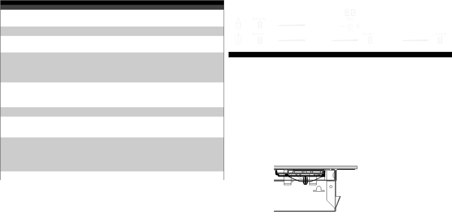
Enter/Exit Menu mode:
1.Touch and hold the Main Power key. The cooktop will beep and turn on when you first touch the key, and it will beep again and turn off after 3 seconds.
2.Touch the hidden service key (just right of the right rear cooking zone indicator on a five-zone cooktop) for three seconds. The cooktop will beep when you first touch the key and again after 3 seconds.
3.The cooktop will enter Menu mode, and a code will appear in the timer display. The code may be “d”, “do”, “S”, or “E”.
4.To exit Menu mode, do not touch any control for 20 seconds. The cooktop will exit Menu mode.
Deactivate Demo mode:
1.Enter Menu mode, and a code will appear in the timer display.
2.Touch the Timer key to cycle through the options until “do” displays. If “do” is not an option, the cooktop is not in Demo mode.
3.Press the + key to deactivate Demo mode. The code in the display will change from “do” to “d”.
Enter/Exit Service mode:
1.Enter Menu mode, and a code will appear in the timer display.
2.Touch the Timer key to cycle through the options until “S” displays.
3.Touch the + key to enter Service mode.
Enter/Exit Error mode:
1.Enter Menu mode, and a code will appear in the timer display.
2.Touch the Timer key to cycle through the options until “E” displays.
3.Touch the + key to enter Error mode.
4.The last 5 error codes will display for 5 seconds each. If the display shows only “E”, there are no errors in the appliance’s memory.
|
|
|
Left Induction Module |
|
|
|
|
Hidden Service Key |
|||||||||
|
|
|
|
UI Display (Error Codes) |
|
|
|||||||||||
|
|
|
Setting Displays |
|
|
|
|||||||||||
|
|
|
|
|
Right Induction Module |
|
|
||||||||||
|
|
|
|
|
|
|
|
|
|
|
|
|
|
|
|||
|
|
|
|
|
|
|
|
|
|
|
|
|
|
|
|||
|
|
|
|
|
|
|
|
|
|
|
|
|
|
|
|||
|
|
1 |
P |
|
|
|
|
|
|
|
Setting Displays |
|
|
||||
|
|
|
|
|
|
|
|
|
|
|
|||||||
|
|
|
|
|
|
|
|
|
|
|
|
|
|
|
|
|
|
|
|
|
|
|
|
|
|
|
|
|
|
|
|
|
|
|
|
|
|
|
|
|
|
|
|
|
|
|
|
|
|
|
|
|
|
|
|
1 |
P |
|
|
|
1 |
|
P |
|
|
1 |
P |
|
|||
|
|
||||||||||||||||
|
|
|
|
|
|
||||||||||||
|
|
|
|
|
|
|
|
|
|
|
|
|
|
|
|
|
|
|
|
|
|
|
|
|
|
|
|
|
|
|
|
|
|
|
|
|
|
|
|
|
|
|
|
|
|
|
|
|
|
|
|
||
ADDITIONAL ERROR (FAULT) CONDITIONS |
|
|
|
|
|
|
|
|
|
|
|
|
|
|
|||
Symptom or failure |
|
Control Display |
|
|
|
Possible cause or condition |
|
|
Suggested Corrective Action |
|
|
||||||
Cannot activate or operate |
|
|
|
|
Power is not connected properly. |
Make sure the cooktop is correctly connected to the power supply. |
|||||||||||
the cooktop |
|
|
|
|
|
|
|
|
|
|
|
|
|
|
|
|
|
|
|
|
|
|
|
Circuit-breaker tripped or fuse |
Make sure that that the breaker is closed or the fuse is good. |
||||||||||
|
|
|
|
|
|
blown |
|
|
|
|
|
|
|
||||
|
|
|
|
|
|
|
|||||||||||
Pan does not heat up. |
|
Normal operation. |
|
|
Pan too small for proper pan detec- |
Use larger pan or this pan on a smaller cooking zone. Refer to |
|||||||||||
|
|
|
|
|
|
tion and only works with low power. |
owner’s guide for proper pan selection. |
|
|
||||||||
|
|
|
Setting indicator |
|
|
Pan not detected. |
Check whether the pots or pans are suitable for induction. Refer to |
||||||||||
|
|
|
flashes. |
|
|
|
|
|
|
|
owners guide for proper pan selection. |
|
|
||||
|
|
|
|
|
|
Induction coil not correctly |
Check the coil wire terminal connections. Ensure that they are |
||||||||||
|
|
|
|
|
|
connected or induction coil open. |
properly connected and tightened. Test continuity of coil (should be |
||||||||||
|
|
|
|
|
|
|
|
|
|
|
less than 1 ohm). |
|
|
|
|||
|
|
|
|
|
|
Distance between coil and glass |
Check whether the coil is properly positioned and touching the glass |
||||||||||
|
|
|
|
|
|
ceramic too large. |
cooktop surface. |
|
|
|
|||||||
|
|
|
|
|
|
|
|
|
|||||||||
Power setting flashes for all |
|
Flashing number |
|
|
Defective induction generator or |
See E8 defective induction module |
|
|
|||||||||
zones of a single induction |
|
|
|
|
missing mains supply |
|
|
|
|
|
|
|
|||||
generator with different pots |
|
|
|
|
|
|
|
|
|
|
|
|
|
|
|
|
|
No power to any cook zone |
|
Normal operation |
|
|
Demo mode activated |
Deactivate Demo mode. See separate box. |
|
|
|||||||||
|
|
|
|
|
|
|
|||||||||||
Single keys are not operable |
|
|
|
|
User interface not correct pressed |
Check build in position of the user interface and correct if neces- |
|||||||||||
|
|
|
|
|
|
to ceramic or defect. |
sary. The LED should be central above the main switch. |
||||||||||
|
|
|
|
|
|
|
|
|
|
|
If some keys or cooking levels are difficult to operate or unstable. |
||||||
|
|
|
|
|
|
|
|
|
|
|
1) Disconnect the appliance from the mains for 30 sec. and try |
||||||
|
|
|
|
|
|
|
|
|
|
|
again. |
|
|
|
|||
|
|
|
|
|
|
|
|
|
|
|
2) If the problem is still there, probably the user interface is either |
||||||
|
|
|
|
|
|
|
|
|
|
|
pressed too little or not close enough to the ceramic glass. Check |
||||||
|
|
|
|
|
|
|
|
|
|
|
if there is a cable between the user interface and the carrier. |
||||||
|
|
|
|
|
|
|
|
|
|
|
Check if the carrier of the user interface is correctly positioned and |
||||||
|
|
|
|
|
|
|
|
|
|
|
all spring elements are present. Also the coils have to be correctly |
||||||
|
|
|
|
|
|
|
|
|
|
|
assembled, so the distance between the support plate and the |
||||||
|
|
|
|
|
|
|
|
|
|
|
ceramic is correct. Otherwise: appliances with carrier, replace the |
||||||
|
|
|
|
|
|
|
|
|
|
|
carrier; appliances with silicon element, put a metal sheet with a |
||||||
|
|
|
|
|
|
|
|
|
|
|
thickness of 1-1.5mm underneath the silicon element in the area of |
||||||
|
|
|
|
|
|
|
|
|
|
|
the keys that are not working. |
|
|
||||
|
|
|
|
|
|
|
|
|
|
|
If these solutions do not help, replace the user interface. |
||||||
Individual cooking zones |
|
None. |
|
|
Test cables & connections. User |
1. Follow instructions for proper use of touch controls. |
|||||||||||
cannot be used or cannot |
|
|
|
|
interface defective. |
2. Replace user interface. |
|
|
|
||||||||
always be used. |
|
|
|
|
|
|
|
|
|
|
|
|
|
|
|
|
|
|
|
|
|
|
|
|
|
|
|
||||||||
Cooking power too low or |
|
Normal operation |
|
|
Ventilation slots obstructed. |
Clear vent openings. |
|
|
|
||||||||
shuts down prematurely. |
|
|
|
|
|
|
|
|
|
|
|
|
|
|
|
|
|
|
|
|
|
Unsuitable pots ( bottom bent). |
Follow owner’s guide for proper pan selection. |
|
|
||||||||||
|
|
|
|
|
|
|
|
||||||||||
|
|
|
|
|
|
Distance between coil and glass |
Check whether the glass ceramic was pushed down when being |
||||||||||
|
|
|
|
|
|
ceramic too large. |
screwed in position and the coil has been correctly positioned. |
||||||||||
H in display when cooking |
|
"H" |
|
|
Temperature sensor defect. |
1. Test coil sensor; it should be approximately 100K ohms at room |
|||||||||||
zone is cold and switched off. |
|
|
|
|
|
|
|
|
|
temperature. Replace coil if resistance is incorrect. |
|||||||
|
|
|
|
|
|
|
|
|
|
|
2. Replace power generator board. |
|
|
||||
Buzzer defect |
|
|
|
|
User interface defect |
Replace user interface |
|
|
|
||||||||
|
|
|
|
|
|
|
|
|
|
||||||||
Single segments of the |
|
|
|
|
User interface defect |
Replace user interface |
|
|
|
||||||||
display are defective |
|
|
|
|
|
|
|
|
|
|
|
|
|
|
|
|
|
 Loading...