


FFRE0633S14
Frigidaire FFRE0633S14, FFRE0633S15, FFRE0633S1E0, FFRE0633S1E1, FFRE0833S1E0 Installation Guide
...
Installation Instructions
For Medium (15,000-18,500 BTU) + Heavy duty (22,000-28,500 BTU) Air Conditioner
READ BEFORE INSTALLING UNIT
INSTALLATION WARNINGS AND CAUTION
Carefully read the installation manual before beginning.
Follow each step as shown.
Observe all local, state, and national electrical codes and by qualified, licensed, authorized personnel only.
Pay attention to danger and safety notices.
To avoid risk of personal injury, property damage, or product damage due to the weight of this device and sharp edges that may
be exposed:
Air conditioners covered in this manual pose an excessive weight hazard. Two or more people are needed to move and install
the unit. Wear protective gloves whenever lifting or carrying the unit. AVOID the sharp metal fins of front and rear coils. To
prevent injury or strain, use proper lifting and carrying techniques when moving unit.
Carefully inspect location where air conditioner will be installed. Be sure it will support the weight of the unit overan extended
period of time.
Handle air conditioner with care.
Make sure air conditioner does not fall during installation.
If a new electrical outlet is required, have the outlet installed by a qualified electrician before installing unit.
NOTE: DO NOT USE ANY SCREWS OTHER THAN THOSE SPECIFIED HERE.
Preliminary instructions:
Do the following before starting to install unit. See illustrations below.
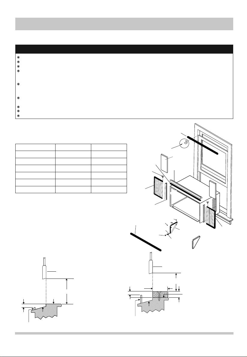
Check dimensions of your unit to determine model type:
Heavy duty
Capacity:
Unit Height:
Unit Width:
Min. Window Opening:
Min. Window Width:
Max. Window Width:
18-5/8″
26-1/2″
19-1/2″
31″
42″
1. Check window opening size: the mounting parts
furnished with this air conditioner are made to install in
a wooden sill double-hung window. The standard parts
are for window dimensions listed above. Open sash to
a minimum of 19″ (483mm). (FIG.1)
2. Check condition of window: all wood parts of window
must be in good shape and able to firmly hold the needed
screws. If not, make repairs before installing unit.
3. Check your storm windows: If your storm window
frame does not allow the clearance required, correct by
adding a piece of wood as shown (FIG.2), or by removing
storm window while room air conditioner is being installed.
FIG.1
sash
1/2″ min
19″ min
inner sill
outer sill
storm window frame or
other obstruction
Medium
15,000~18,500 BTU22,000~28,500 BTU
17-5/8″
23-5/8″
18-1/2″
28″
40-1/2″
foam gasket
washer head
locking screw
frame
assembly
(left)
side retainer
bottom rail
seal to unit
FIG.2
1/2″ min
outer sill
storm window frame or
other obstruction
window sash seal
safety lock and
1/2″ long hex
head screw
1/2″ long
screws and
locknuts
locknut 3/4″
long flat
head bolt
sash
1-1/2″ min
insulation
panel
top angle
window
support bracket
sill angle
bracket
19″ min
inner sill
board thickness as
required, along entire inner
window sill; fasten to inner
sill with two nails or screws.
16120300A04422
frame
assembly
(right)
1
Installation Instructions
4. Check for anything that could block airflow
Check area outside of window for things such as shrubs, trees, or awnings. Inside, be sure furniture, drapes, or blinds
will not stop proper air flow.
5. Check the available electrical service
Power supply must be the same as that shown on the unit serial
nameplate. (See Use & Care Guide for serial plate location.) Power
cord is 48″ long. Be sure you have an outlet near.
All models have a 3-prong service plug to provide proper service and
safe positive grouding. Do not change plug in any way. Do not use an
adapter plug. If your present wall outlet does not match your plug, call
a qualified electrician to make the needed change.
6. Carefully unpack air conditioner
Remove all packing material. Protect floor or other stable flat surface
with covering to prevent scratches from unit. With the aid of an
assistant, remove unit from styrofoam base and rest on protected
surface. Move and install unit with the aid of an assistant. Save
packing and shipping box for future unit storage.
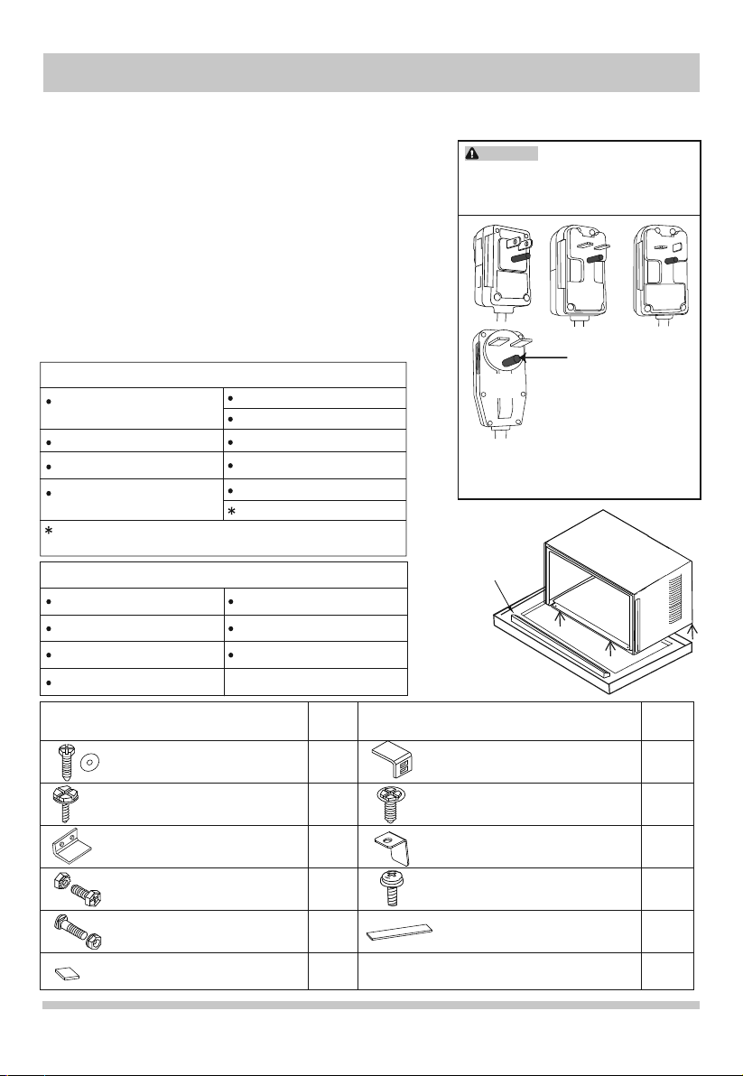
Accessory Kit includes
Hardware bag(shipped inside
window support brackets)
Window support bracket (2)
Side retainer (2)
Window Filler Panel (2)
MEDIUM models only HEAVY DUTY top angle rail can be
found in carton base packaging (FIG.3)
Tools Required
a large flat blade screwdriver tape measure
adjustable wrench or pliers
level Socket wrenches
Phillips screwdriver
Foam gasket
Window sash seal
Insulation panel (2)
Ruler
Bottom rail seal
Top angle rail
pencil
HEAVY DUTY
(22,000~28,500BTU)
TOP ANGLE RAIL
WARNING
Avoid fire hazard or electric
shock. Do not use an extension cord or an
adaptor plug. Do not remove any prong
from the power cord.
115V
15A
230V
30A
Remark:
The appearance of actual plug may
be slightly different from the line drawing shown
in the figure. The line drawings are for
reference only.
230V
15A
Grounding Prong
Do not, under any
circumstances, cut,
remove or bypass the
grounding prong.
230V
20A
FIG.3
Hardware ( in plastic bag)
7/16″ Locking Screw and Flat
Washer for window filler panels
1/2″ Long hex head screw
Safety Lock
1/2″ Long Screw
and locknut
3/4″ Long Flat Head Bolt
and Locknut
foam insert
2
Qty.
2 ea
7
1
4 ea
2 ea
2
Hardware ( in plastic bag)
Sill Angle Bracket
Long hex-head locking screw for top
angle rail, side retainer 5/16″ long
Safety Lock
(for Vinyl-Clad window)
Locking screw #10 X 1/4″ panhead
Phillips screws (for Vinyl-Clad window)
weather stripping
(10″X3/4″X1/12″)
Qty.
2
10
2
2
5
Installation Instructions
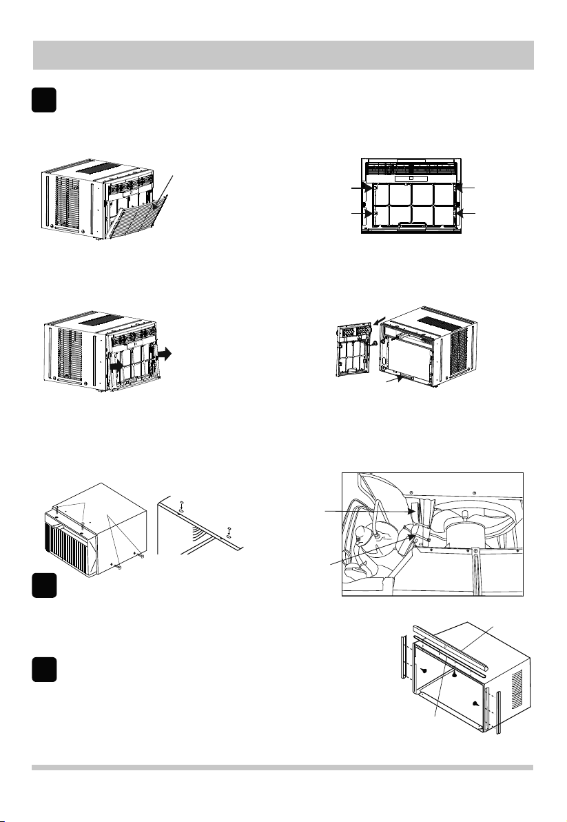
Remove Air Conditioner from Cabinet
Window Mounting
1
NOTE: Remove any packaging material from cabinet exterior.
1. Pull down on front grille from upper edge. Lift front grille upwards and place to one side. (See FIG.1)
2. Remove filter. To remove, grasp in the middle on each side. Bow filter out to detach top edge from tabs. Once top
is free, lift filter up and out.
FIG.1
3. Locate the four Front Panel screws and remove. These screws will be needed to re-install the Front Panel later
(See FIG.2).
4. Push metal cabinet side inward to release plastic tabs on each side of Front Panel (see Fig. 3).
5. Rotate Front Panel up until top tabs are free. Pull panel straight out. When pulling out, front panel will also pull free
from vent control lever. Depress latch on electronics plug (on some models) to disconnect.
6. Remove Front Panel from unit (see Fig. 4).
FIG.3
7. Remove shipping screws from top of unit and also on both sides by the base if installed. (See FIG.5)
8. With the aid of an assistant, hold the cabinet while pulling on the base pan handle (see FIG. 4), and carefully
remove the air conditioner from cabinet.
9. Add two foam inserts to holes in top of cabinet where shipping screws were removed from. (See FIG.6)
10. Except 22,000BTU model, other heavy duty models (24,000~28,500BTU) come with internal shipping packaging.
THIS PACKAGING AND PLASTIC TIES MUST BE REMOVED PRIOR TO INSTALLING THE AIR CONDITIONER
BACK INTO THE CABINET. (See FIG.7)
11. Remove plastic wrapping from all points on power cord.
FIG.5
shipping
screws
Front Grille
base pan handle
Shipping Packaging
FIG.2
FIG.4
FIG.7
FIG.6
Install Top Angle Rail and Side Retainers
2
1. Remove adhesive strip coating from foam gasket. Attach adhesive side of gasket to bottom of top angle rail. Insert 4
screws from inside of cabinet and secure to top angle rail.
2. From inside of cabinet insert 3 screws to attach each side retainer as shown
in Fig. 8. Attach side retainers with flat side against cabinet and angled edge toward
rear of cabinet.
Assemble Window Filler Panels
3
1. Place cabinet on floor, a bench, or a table.
2. Slide "I" section at end of window filler panel into side retainer on each side of the
cabinet (see FIG. 9 and FIG.10).
3. On each side of cabinet, insert top and bottom legs of window filler panel
frame into channel in the top and bottom angle rails.
4. Insert a 7/16" locking screw and flat washer into hole on top leg of each window filler panel (see section 6). Do not
totally tighten. Allow leg to slide freely. Screws will be tightened after Section 6.
Plastic tie
FIG.8
Foam Gasket
Top angle rail
3
 Loading...