


|
Installation |
Over the Range |
|
|
Instructions |
Microwave Oven |
|
|
|
|
|
|
|
|
|
|
Questions? Call 1-800-944-9044(US) or 1-800-265-8352(Canada) |
||
|
|
|
|
|
|
|
|
|
BEFORE YOU BEGIN |
|
|
|
Read these instructions completely and carefully. |
|
|
• Note to Consumer – Keep these |
|||
|
• IMPORTANT – Save these |
instructions for future reference. |
|
|
• Skill level – Installation of this appliance requires |
|
|
|
instructions for local inspector’s use. |
basic mechanical and electrical skills. |
|
|
• IMPORTANT – Observe all |
|
|
|
• Proper installation is the responsibility of the installer. |
|
|
|
governing codes and ordinances. |
• Product failure due to improper installation is not |
|
|
• Note to Installer – Be sure to leave these |
covered under the Warranty. |
|
|
instructions with the Consumer. |
|
|
|
|
|
|
|
|
|
|
|
|
|
|
|
|
|
|
READ CAREFULLY.
KEEP THESE INSTRUCTIONS.
p/n A06823421
January 2020
Installation Instructions
CONTENTS |
|
|
General information |
|
|
Important Safety Instructions .................................. |
3 |
|
Electrical Requirements .......................................... |
3 |
|
Damage – Shipment/Installation.............................. |
4 |
|
Parts Included.......................................................... |
4 |
|
Tools You Will Need ................................................ |
5 |
|
Mounting Space ...................................................... |
5 |
|
Step-by-step installation guide |
|
|
Placement of The Mounting Plate ...................... |
6–8 |
|
|
Removing the Mounting Plate ...................... |
6 |
|
Finding the Wall Studs .................................. |
6 |
|
Determining Wall Plate Location .................. |
7 |
|
Aligning the Wall Plate ................................ |
8 |
Installation Types............................................... |
.....9 |
|
A |
Recirculating ........................................... |
10 –13 |
|
|
10 |
|
Attach Mounting Plate to Wall ............... |
|
|
Preparation of Top Cabinet ................... |
11 |
|
Check Blower Plate ............................... |
11 |
|
Mount the Microwave Oven ............ |
11–12 |
|
Installing or Change the |
|
|
Charcoal Filter .................................. |
12-13 |
Hood Exhaust .................................................... |
14-15 |
|
B |
Outside Back Exhaust ............................ |
16–19 |
|
Preparing Rear Wall for |
|
|
Outside Back Exhaust.......................... |
16 |
|
Remove Blower Plate............................ |
..16 |
|
Attach Mounting Plate to Wall ............ |
17 |
|
Preparation of Top Cabinet ................ |
17 |
|
Adapting Microwave Blower |
|
|
for Outside Back Exhaust................ |
17–18 |
|
Mount the Microwave Oven ................ |
19 |
C Outside Top Exhaust ............................ |
20-23 |
Attach Mounting Plate to Wall............ |
20 |
Preparation of Top Cabinet................ |
21 |
Adapting Microwave Blower for |
|
Outside top Exhaust .................. |
21-22 |
Checking for Proper Damper |
|
Operation ............................................ |
22 |
Mount the Microwave Oven ......... |
22-23 |
Adjust the Exhaust Adaptor ................ |
23 |
Connecting Ductwork.......................... |
23 |
Before You Use Your Microwave .......................... |
24 |
Template Information............................................. |
25 |
EN-2
Installation Instructions
IMPORTANT SAFETY INSTRUCTIONS
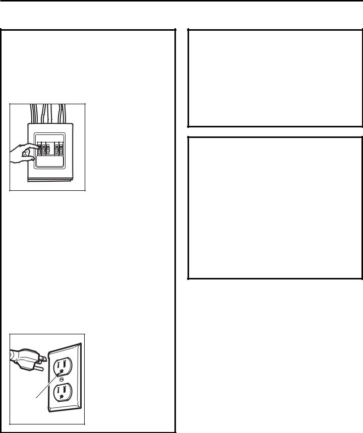
This product requires a three-prong grounded outlet. The installer must perform a ground continuity check on the power outlet box before beginning the installation to ensure that the outlet box is properly grounded. If not properly grounded, or if the outlet box does not meet electrical requirements noted (under ELECTRICAL REQUIREMENTS), a qualified electrician should be employed to correct any deficiencies.
CAUTION: For personal safety, remove house fuse or open circuit breaker before beginning installation to avoid severe or fatal shock injury.
CAUTION: For personal safety, the mounting surface must be capable of supporting the cabinet load, in addition to the added weight of this 63–85 pound (28.5–38.5 kg) product, plus additional oven loads of up to 50 pounds (22.7 kg) or a total weight of 113–135 pounds (51.3–61.2 kg).
CAUTION: For personal safety, this product cannot
be installed in cabinet arrangements such as an island or a peninsula. It must be mounted to BOTH a top cabinet AND a wall.
NOTE: For easier installation and personal safety, it is recommended that two people install this product.
IMPORTANT – PLEASE READ CAREFULLY. FOR PERSONAL SAFETY, THIS APPLIANCE MUST BE PROPERLY GROUNDED TO AVOID SEVERE OR
FATAL SHOCK.
Ensure proper |
ground exists |
before use |
The power cord of this appliance is equipped with a three-prong (grounding) plug which mates with a standard three-prong (grounding) wall receptacle to minimize the possibility of electric shock hazard from this appliance.
You should have the wall receptacle and circuit checked by a qualified electrician to make sure the receptacle is properly grounded.
Where a standard two-prong wall receptacle is encountered, it is very important to have it replaced with a properly grounded three-prong wall receptacle, installed by a qualified electrician.
DO NOT, UNDER ANY CIRCUMSTANCES, CUT, DEFORM OR REMOVE ANY OF THE PRONGS FROM THE POWER CORD. DO NOT USE WITH AN EXTENSION CORD.
ELECTRICAL
REQUIREMENTS
Product rating is 120 volts AC, 60 Hertz, 15 amps and 1.6 kilowatts. This product must be connected to a seperate and dedicated supply circuit of the proper voltage and frequency. Wire size must conform to the requirements of the National Electrical Code or the prevailing local code for this kilowatt rating.
The power supply cord and plug should be brought to a seperate and dedicated 15to 20ampere branch circuit single grounded outlet. The outlet box should be located in the cabinet above the microwave oven. The outler box and supply circuit should be installed by a qualifed electrician and conform to the National Electrical Code or the prevailing local code.
EN-3
Installation Instructions
DAMAGE—SHIPMENT/ INSTALLATION
•If the unit is damaged in shipment, return the unit to the store in which it was bought for repair or replacement.
•If the unit is damaged by the customer, repair or replacement is the responsibility of the customer.
•If the unit is damaged by the installer (if other than the customer), repair or replacement must be made by arrangement between customer and installer.
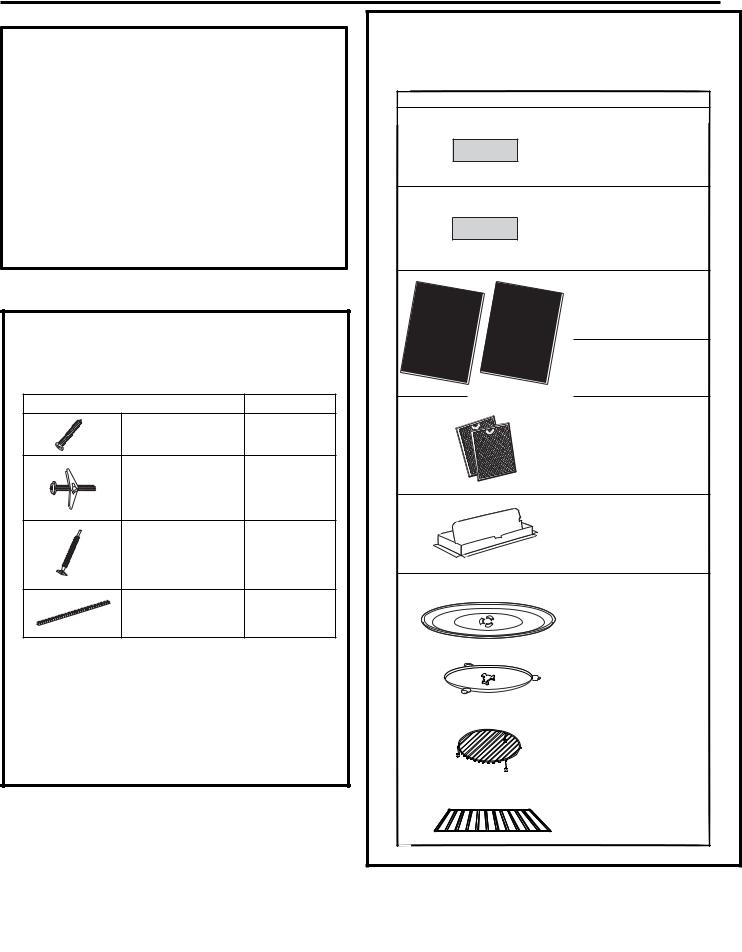
PARTS INCLUDED
HARDWARE PACKET
PART |
QUANTITY |
Wood Screws |
2 |
(1⁄4“ x 2“) |
|
Toggle Bolts (and |
2 |
wing nuts) (3⁄16“ x 3“) |
|
Self-Aligning Machine |
3 |
Screws (1⁄4“-28 x 31⁄4“) |
|
Nylon Grommet |
1 |
(for metal cabinets) |
|
You will find the installation hardware contained in a packet with the unit. Check to make sure you have all these parts.
NOTE: Some extra parts are included.
PARTS INCLUDED (CONT.)
ADDITIONAL PARTS
PART |
|
|
|
|
QUANTITY |
||
|
|
|
|
|
|
Top Cabinet |
1 |
|
|
|
|
|
|
Template |
|
|
|
|
|
|
|
|
|
|
|
|
|
|
|
Rear Wall |
1 |
|
|
|
|
|
|
Template |
|
|
INSTALLATION |
USE |
|
Installation |
1 |
||
|
IN |
STRUCTIONS |
|
|
|||
|
|
& |
CARE |
Instructions |
|||
|
|
|
|
MANUAL |
|
||
|
|
|
|
|
|
Use & Care |
1 |
|
|
|
|
|
|
Manual |
|
|
|
|
|
|
|
Separately |
|
|
|
|
|
|
|
Packed |
2 |
|
|
|
|
|
|
Grease |
|
|
|
|
|
|
|
|
|
|
|
|
|
|
|
Filters |
|
|
|
|
|
|
|
Exhaust |
1 |
|
|
|
|
|
|
adaptor |
|
|
|
|
|
|
|
Glass |
1 |
|
|
|
|
|
|
Tray |
|
|
|
|
|
|
|
Turntable |
1 |
|
|
|
|
|
|
Ring |
|
For |
some |
models |
|
|
|
|
|
|
|
|
|
|
|
Convection |
1 |
|
|
|
|
|
|
wire rack |
|
For |
some |
models |
|
|
|
|
|
|
|
|
|
|
|
Shelf |
1 |
EN-4
Installation Instructions
Tools you will need:
•Tape measure
•Hole saw
•Stud finder or hammer
•Level
•Duct and masking tape
•Scissors
•#1 Phillips screw driver
•Electric drill
•3/16”, 1/2”, 5/8” drill bit
•Filler wood blocks for recessed bottom cabinets
•Tin snips
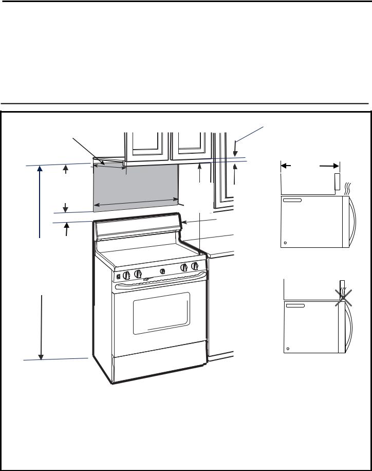
13" Max
(33 cm)
16 ½"
(41.9 cm)
2"(5.1 cm)
66"
(167.6 cm)
or more from the floor to the top of the microwave
Mounting Space |
¼" Min |
|
|
|
Clearance |
13" MAX. (33 cm)
.2 |
cm) |
30"(76 |
|
30"
(76.2 cm) min.
Backsplash
Cabinet
Cabinet
•The space between the cabinets must be 30" (76.2 cm) wide and free of obstructions.
•If you are going to vent your microwave oven to the outside, see Hood Exhaust Section for exhaust duct preparation
•When installing the microwave oven beneath smooth, flat cabinets, be careful to follow the instructions on the top cabinet template for power cord clearance.
•As a guide to installation, see page 26 for Mounting Template Information.
•If the cabinet depth, including the cabinet doors, is more than 13”, then the unit must be spaced out from wall using adequate materials supporting 150 lbs to allow proper top vent air exhaust/intake.
EN-5
Installation Instructions
1 PLACEMENT OF THE MOUNTING PLATE
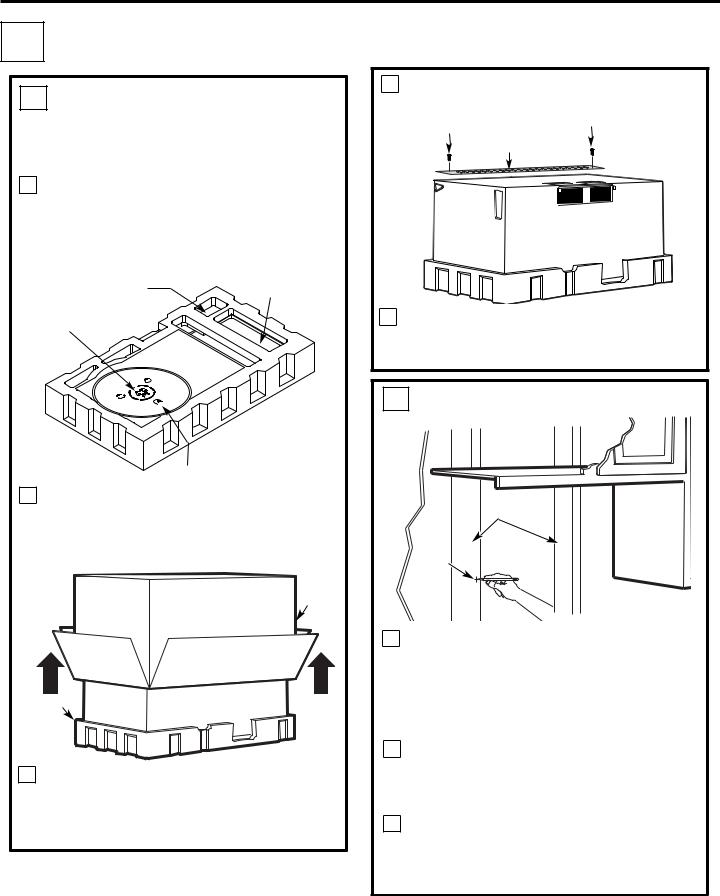
A. REMOVING THE MICROWAVE OVEN FROM THE CARTON/ REMOVING THE MOUNTING PLATE
1Remove the installation instructions,use and care, exhaust adapter, turntable ring, shelf, filters, glass tray and the small hardware bag.Do not remove the Styrofoam protecting the front of the oven. please note: Do Not Remove plastic plug protective cover until just before hanging the unit.
Small Hardware Bag |
Exhaust Adapter |
Filters and Turntable
Ring below glass tray
Glass Tray
2Fold back all 4 carton flaps fully against carton sides. Then carefully roll the oven and carton over onto the top side. The oven should be resting in the Styrofoam.
Carton
Styrofoam
3 Pull the carton up and off the oven.
4Cut the middle of the outer protective plastic bag to remove the mounting plate
Screws Screws
Mounting Plate
5Remove the screws from each end of the mounting plate. This plate will be used as the rear wall template and for mounting. Reinstall the screws into the holes where they were removed.
B. FINDING THE WALL STUDS
Wall
Studs
Center
1Find the studs, using one of the following methods:
A.Stud finder – a magnetic device which locates nails.
B.Use a hammer to tap lightly across the mounting surface to find a solid sound. This will indicate a stud location.
2After locating the stud(s), find the center by probing the wall with a small nail to find the edges of the stud. Then place a mark halfway between the edges. The center of any adjacent studs should be 16ω (40.6 cm) or 24ω (61 cm) from this mark.
3 Draw a line down the center of the studs.
THE MICROWAVE MUST BE CONNECTED TO AT LEAST ONE WALL STUD.
EN-6

Installation Instructions
C. DETERMINING WALL PLATE LOCATION UNDER YOUR CABINET
Plate position-beneath flat bottom cabinet
1/4" Minimum clearance
|
|
|
|
|
|
|
|
|
|
² |
|
|
||
|
|
16-1/22″ |
|
|
|
|
|
|
|
|
|
|
|
|
C
At least 30″
Draw a vertical line on the wall at the center of the 30″ wide space.
Tape the Rear Wall Template onto the wall matching the centerline and touching the bottom of the cabinet.
Plate position-beneath recessed bottom cabinet with front overhang
|
|
|
|
|
|
|
|
|
|
|
|
|
|
|
|
|
|
Draw a line on the
back wall equal to the depth of the front
overhang.
1/4" Minimum clearance
1/4" Minimum clearance


C
30300″to Cooktop
Plate position-beneath framed recessed cabinet bottom
1/4" Minimum clearance


C
30300″to Cooktop
Draw a vertical line on the wall at the center of the 30″ space.
Tape the Rear Wall Template onto the wall matching the centerline and touching the bottom cabinet frame.
Your cabinets may have decorative trim that interferes with the microwave installation. Remove the decorative trim to install the microwave properly and to make it level.
THE MICROWAVE MUST BE LEVEL.
Use a level to make sure the cabinet bottom is level.
If the cabinets have a front overhang only, with no back or side frame, install the mounting plate down the same distance as the front overhang depth. This will keep the microwave level.
1Measure the inside depth of the front overhang.
2Draw a horizontal line on the back wall an equal distance below the cabinet bottom as the inside depth of the front overhang.
3For this type of installation with front overhang only, align the mounting tabs with this horizontal line, not touching the cabinet bottom as described
in Step D.
EN-7
Installation Instructions
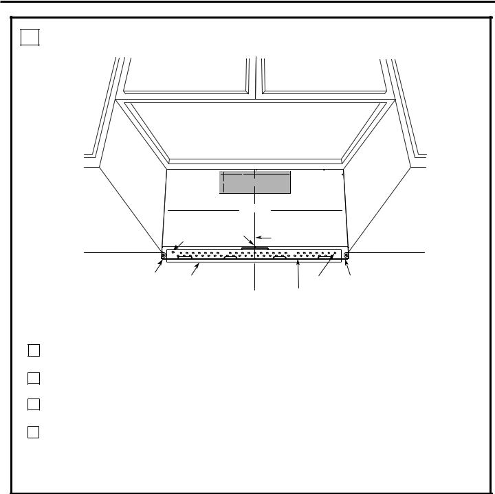
D. ALIGNING THE WALL PLATE
NOTE: IT IS VERY IMPORTANT TO
READ AND FOLLOW THE DIRECTIONS
IN THE INSTALLATION INSTRUCTIONS
BEFORE PROCEEDING WITH THIS
REAR WALL TEMPLATE.
4"
016'
|
3/8" TO EDGE |
12" |
Trim the rear wall template along the dotted line. |
( %76 176 (14 *14+<106#.1765+&' ':*#756
%76 *1.' 6*417)* 4'#4 9#.. (14 ':*#756 #ਸ਼
016'
Locate and mark holes to align with holes in the mounting plate.
IMPORTANT:
LOCATE AT LEAST ONE STUD ON EITHER SIDE OF THE CENTERLINE.
MARK THE LOCATION FOR 2 ADDITIONAL, EVENLY SPACED TOGGLE BOLTS IN THE MOUNTING PLATE AREA.
Hole B
%#76+10 Ä +( ':*#756 #ਸ਼ +5 215+6+10'& 1765+&'
4'%1//'0&'& &+/'05+10 )4'#5'Ä.#&'0 #+4 9+..
&+5%*#4)' +061 *175' 5647%674'
/+0+/7/ 9+&6* 4'37+4'& |
|
|
||
|
|
|
Locate and mark holes to align with holes in the |
|
4'#4 9#.. 6'/2.#6' |
mounting plate. |
|||
IMPORTANT: |
||||
THE CENTERLINE. |
||||
|
|
|
LOCATE AT LEAST ONE STUD ON EITHER SIDE OF |
|
|
|
|
MARK THE LOCATION FOR 2 ADDITIONAL, EVENLY |
|
Centerline |
|
|
SPACED TOGGLE BOLTS IN THE MOUNTING PLATE |
|
|
|
AREA. |
||
% |
Draw a Vertical Line |
|||
notches |
||||
|
on Wall from Center |
|||
|
|
of Top Cabinet |
||
$ |
& |
% |
# |
|
Horizontal Line |
Area E |
C
L
Hole A Horizontal Line
Draw a horizontal line on wall at the bottom of “Rear Wall Template”.
1
2
3
4
Draw a vertical line on the wall at the center of the 30" wide space.
Draw a horizontal line on the wall at the bottom of “Rear Wall Template”.
Find a wall stud in area "E" of mounting plate Refer to section 1B. Finding the wall studs.
For attaching the mounting plate into stud drill a 3/16" hole into wood stud. Drill a 5/8" hole for toggle bolt in 1 other location (Hole A or Hole B)
NOTE: DO NOT MOUNT THE PLATE AT THIS TIME.
NOTE: Holes A and B are inside area E. If neither of Holes A and B are not in a stud, find a stud somewhere in area E and draw a circle to line up with the stud. It is important to have at least one wood screw mounted firmly in a stud to support the weight of the microwave. Set the mounting plate aside.
EN-8
 Loading...