


Window Installation Instructions
Room Air Conditioners
AUTO |
|
AUTO |
°F °C |
CONTINUOUS |
|
AUTO |
|
SYSTEM |
FAN MODE |
SCHEDULE |
FAN SPEED |
Standard Chassis Models
115-Volt: SS08, SS10, SS12, SS14, SM15, 208-230-Volt: SS12, SM18,SM21 SL24, SL28, SL36
115-Volt: EQ08,YS10
208-230-Volt: ES12, ES16, YS12, EM18,
YM18, EM24, EL24, EL36, YL24
93001014_00
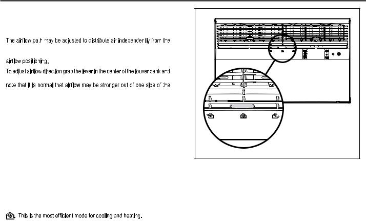
Airflow Selection and Adjustment
Air flow direction adjustment
left or right side of the discharge opening. Each of the banks of louvers can be directed left, right, up or down in order to achieve the most optimum
move it in the direction that you would like the air to be directed. Please
louvers than the other.
Fresh air and exhaust control
Your air conditioner has the ability to bring fresh air into the room or exhaust stale air out of the room. The control slide is found on the upper part of the unit (See Figure 13).
TO BRING IN FRESH AIR – Move the lever to the Fresh Air  position which allows outside air to enter the room. This is useful in fall and spring as a means of bringing in fresh outside air when using FAN ONLY . It can also be used in the summer with the compressor in the Cooling Mode if you wish.
TO EXHAUST INDOOR AIR – Move the lever to the Exhaust  position. This will allow stale air to be expelled to the outside of the dwelling. This is especially handy in the spring or fall when indoor air tends to get stale, or after a social gathering involving smokers, or to remove cooking odors.
BEST PERFORMANCE – Move the lever to the Re-Circulate Position
Figure 13 |
FRR008 |
17

Installation Instructions
READ THIS FIRST! Electrical Requirements
 WARNING
Electrical Shock Hazard
Make sure your electrical receptacle has the same configuration as your air conditioner’s plug. If different, consult a Licensed Electrician.
Do not use plug adapters. Do not use an extension cord. Do not remove ground prong.
Always plug into a grounded 3 prong oulet. Failure to follow these instructions can result in death, fire, or electrical shock.
IMPORTANT: Before you begin the actual installation of your air conditioner, check local electrical codes and the information below. Your air conditioner must be connected to a power source with the same alternating current (A.C.) voltage and amperage as marked on the name plate located on the chassis. Only A.C. can be used. Direct Current (D.C.) cannot be used.
CIRCUIT PROTECTION – Use on single outlet circuit only. An overloaded circuit will invariably cause malfunction or failure of an air conditioner, therefore, it is necessary that the electrical protection is adequate. Due to momentary high current demand when the air conditioner starts, use a "TIME DELAY" fuse or a HACR type circuit breaker. Consult your dealer or power company if in doubt.
Refer to the electrical name plate located on the air conditioner chassis (See page 2) to determine the correct fuse or circuit breaker amperage for your model (See Table 1 on Page 6 for electrical receptacle types).
The power cord has a plug with a grounding prong and a matching receptacle is required.
The following instructions are for standard chassis model groups
sizes listed in Table 3.
Table 3
MODEL DESIGNATION |
CABINET SIZE (H x W x D) |
|
|
SMALL CHASSIS - SS, |
15 15⁄16" x 25 15⁄16" x 29" (405 mm x |
ES, YS |
660 mm x 737 mm) |
MEDIUM CHASSIS - SM, |
17 15⁄16" x 25 15⁄16" x 29" (455 mm x |
EM, YM |
660 mm x 737 mm) |
LARGE CHASSIS - SL, |
20 3⁄16" x 28" x 35 1⁄2" (513 mm x 711 |
EL, YL |
mm x 851 mm) |
 WARNING
MOVING PARTS HAZARDS
*Do not operate unit out of sleeve or with front grille removed.
*Do not place hands in blower or
fan blade areas.
Failure to do so can result in serious injury.
 CAUTION
Excessive Weight Hazard
Use two or more people when installing your air conditioner.
Failure to do so can result in back or other injury.
Recommended Tools
1.Power Drill
2.5/32" Drill Bit
3.Gloves
4.Carpenters Level
5.5/16" Wrench
6.1/4" Wrench
7.#2 Phillips Screw Driver
8.Putty Knife or (wood stir stick)
|
|
4 |
1 |
5/16 |
|
|
|
|
|
|
1/4 |
|
5 |
6 |
|
5/16 |
1/4 |
2 |
|
|
|
7 |
8 |
3 |
ITEMS NOT TO SCALE |
|
18
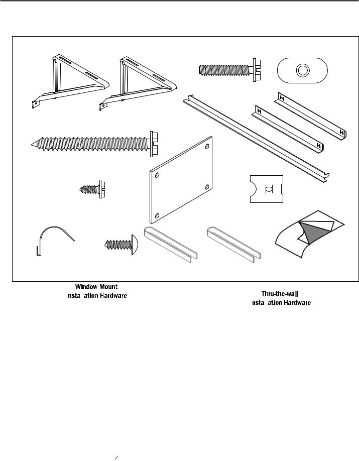
INSTALLATION HARDWARE AND ACCESSORY DETAIL
|
|
|
ITEM 2 |
ITEM 3 |
|
|
|
|
|
|
ITEM 1 |
|
|
|
|
|
|
ITEM 5 |
ITEM 6 |
|
ITEM 4 |
|
|
|
|
ITEM 7 |
|
ITEM 8 |
ITEM 9 |
ITEM 10 |
ITEM 11 |
ITEM 12 |
ITEM 13 |
ITEM 14 |
ITEMS NOT TO SCALE |
|
|
|
FRR009 |
|
|
|
|
|
|
|
|
|
|
|
|
|
|
|
|
|
|
ITEM |
|
DESCRIPTION |
|
QTY. |
||
NO |
|
|
||||
|
|
|
|
|
|
|
|
SHELL MOUNTING PARTS |
|
2 |
|||
|
|
|||||
1 |
SUPPORT BRACKET |
|
||||
2 |
SCREW, 10-24 x 1" HEX HEAD |
|
4 |
|||
3 |
10-24 FLAT WELD NUT |
|
4 |
|||
4 |
SCREW, SHEET METAL #12 x 2" |
|
7 |
|||
|
|
|
|
|
|
|
5 |
WINGBOARD ANGLE MOUNTING |
|
1 |
|||
WINGBOARD ANGLE, TOP |
|
|||||
|
2 |
|||||
6 |
WINGBOARD ANGLE, SIDE |
|
||||
|
2 |
|||||
7 |
SCREW, SHEET METAL #8 x 3 8" |
|
||||
|
|
|||||
|
|
|
|
|
|
|
8 |
WINGBOARD MOUNTING PARTS |
|
1 |
|||
WINGBOARD (MASONITE) |
|
|||||
9 |
"J" TYPE SPEED NUT |
|
4 |
|||
10 |
WINGBOARD CLIP (SPRING STEEL) |
|
4 |
|||
11 |
SCREW, #8 x ½" PHILLIPS TRUSS HD. |
|
4 |
|||
|
|
|
|
|
|
|
|
WINDOW SEALING |
|
|
|||
12 |
WINDOW SEAL GASKET (DARK FOAM) |
|
1 |
|||
13 |
CHASSIS SEAL GASKET (LIGHT FOAM) |
|
1 |
|||
14 |
R1 INSULATION PANEL (GREY FOAM) |
|
1 |
|||
|
|
|
|
|
|
|
|
|
|
|
|
|
|
|
|
|
|
|
ITEM |
|
DESCRIPTION |
QTY. |
||
NO |
|
||||
|
|
|
|
|
|
|
MOUNTING PARTS |
|
|||
4 |
SCREW, SHEET METAL #12A x 2” |
7 |
|||
13 |
CHASSIS SEAL GASKET (LIGHT FOAM) |
1 |
|||
|
|
|
|
|
|
NOTE: Kühl + models do not come with window mounting components. When mounting a cooling and heating model a window installation kit must be purchased separately.
KWIKS – For all ES and YS models.
KWIKM – For all EM and YM models.
KWIKL – For all EL and YL models.
19
Standard Window Installation
NOTE: Hardware and accessories used during installation are shown on page 18. Each part will be referred as Item No.
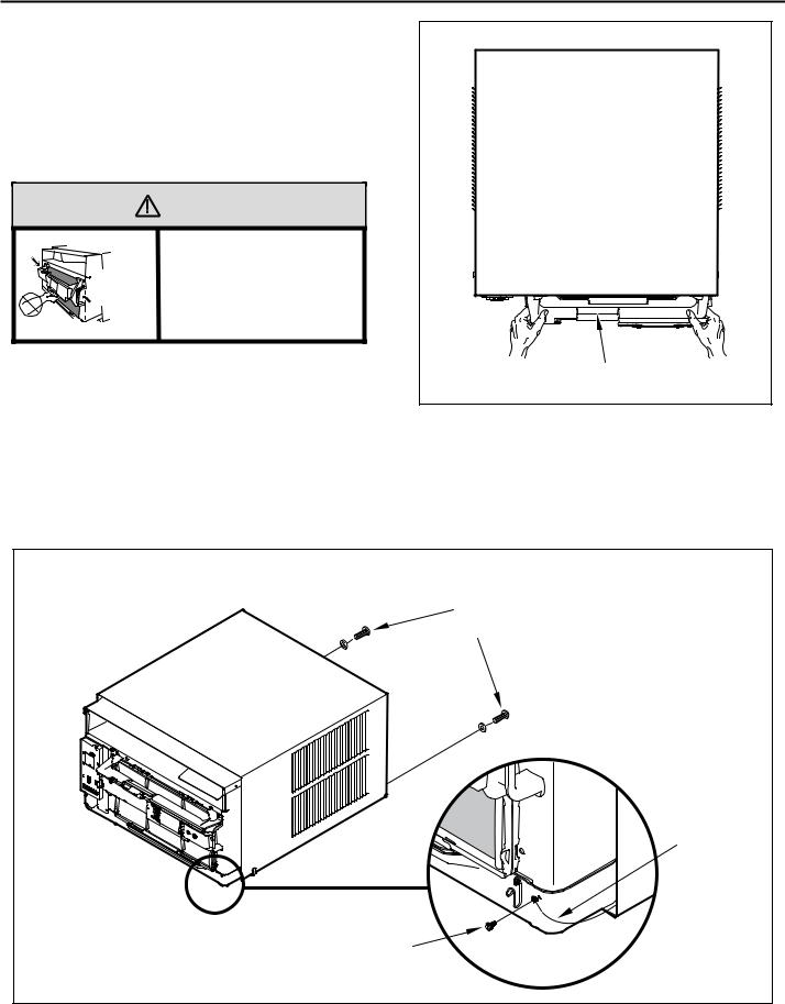
STEP 1. Remove the chassis Entrygard retainer by removing the far right screw (See Figure 14), save this screw to reattach the chassis retainer after installation (Step 12). Also, remove and discard the two retainer screws and washers located at the rear of the unit (See Figure 14).
|
CAUTION |
|
Handle Use |
Use Handle |
Use handle on both sides to |
pull unit from sleeve. |
|
Locations |
|
[both sides] |
Do not push, pull or lift from |
|
|
|
center of support. |
STEP 2. Hold the cabinet stationary, then use the hand grips on both ends of the control unit support bracket to pull the chassis out of the cabinet (See Figure 15).
STEP 3. Remove the large white foam blocks used to restrain the compressor during shipment (See Figure 16). Inspect base pan for dislodged white foam blocks and remove. Do not remove any other foam parts.
Figure 15
CONTROL UNIT
SUPPORT BRACKET
FRR012
STEP 4. Anchor the side angles (Item 6) by engaging the tabs of the lower sill plate (See Figure 17, Detail B-2) with the loops of the side angle. Engage the tabs of the top angle (Item 5) with the top loops of the side angle (See Figure 17, Detail B-1). Install two (2) screws (Item 7) to secure the top angle tabs and the side angle to the cabinet (See Figure 17, Detail B-1).
Figure 14 |
RETAINER SCREWS |
AND WASHERS |
ENTRYGARD |
RETAINER |
WIRE |
FAR RIGHT |
SCREW |
FRR011 |
20 |
 CAUTION
Remove Shipping Blocks
Prior to operating the unit remove the foam shipping blocks.
Failure to do so may result in damage to the unit which is not covered by the manufacturer’s warranty!
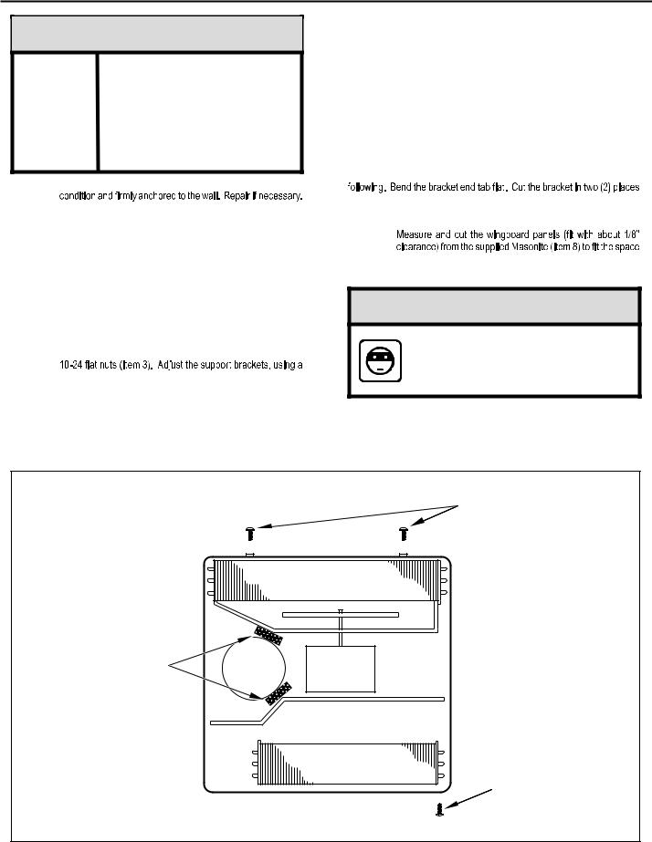
STEP 5. Check the window sill and frame to be sure they are in good
STEP 6. CABINET MOUNTING – Raise the lower window 1/4" more than the height of the cabinet. Carefully slide the cabinet through the opening until the lower sill plate channel rests behind the window sill and the top angle rests against the window (See Figure 18). Center the cabinet within the opening. Drill three (3) 5/32" diameter pilot holes into window sill using the holes in the cabinet sill plate as a guide. Install
three (3) #12 x 2" long screws (Item 4) (See Figure 18).
STEP 7. OUTSIDE SUPPORT MOUNTING – Refer to Figures 19 and 20. Assemble the support brackets (Item 1) to the bottom of the cabinet with four (4) 10-24 1” long screws (Item 2) and four
combination of the elongated holes of the bracket and different hole locations in the cabinet, to bring the bottom support bracket pads in contact with the wall. A 1" x 4" or 2" x 4" SPACER SHOULD BE USED BETWEEN THE WALL AND SUPPORT THE BRACKETS WHEN INSTALLED ON ALUMINUM OR VINYL SIDING. Drill 5/32" diameter pilot holes and secure the brackets to the wall with two (2) 12A x 2" long screws (Item 4).
NOTE: DO NOT LEVEL the cabinet from front to back. Make sure there is approximately 3/8” to 1/2” slope (1/8 to 1/4 bubble on level) toward the outside of the house.
Adjust the support brackets to provide an inside-to-outside slope for excess condensation drainage (Refer to Standard Window Installation, Figures 19 through 23). Tighten all screws.
Alternate support method A: If you have a wide window sill which prevents you from mounting the brackets as shown in Figure 22, try the following: Using the elongated holes and different hole locations in the cabinet, set the placement of the bracket to support the unit’s weight (Figure 22). Tighten all screws.
Alternate support method B: If the window ledge gap is narrow, try the
as shown in Figure 23. Bend the short piece so it will be vertical when installed. Adjust the placement as required. Tighten all screws.
STEP 8.
between the window side channels and cabinet. (Figure 24). Make sure you include the depth of the window channel.
NOTICE
For YOUR security and safety, YOU must provide a means of preventing the upper part of the window from opening.
STEP 9. To assemble the wingboard panels, push on the "J" type speed nuts (Item 9) and spring steel clips (Item 10) (See Figures 25) on page 26. Secure each panel with two (2) screws (Item 11).
Figure 16 |
TOP VIEW OF UNIT |
|
|
|
REMOVE AND DISCARD |
|
SCREWS |
|
BACK |
LEFT SIDE |
|
RIGHT SIDE |
|
REMOVE AND DISCARD |
COMPRESSOR |
FAN MOTOR |
|
FOAM BLOCKS |
|||
|
|
EVAPORATOR COIL |
|
|
REMOVE AND SAVE |
FRONT |
SCREW FOR |
RE-INSTALLATION |
FRR045
21
 Loading...