


2008
Service Manual
Compact Programmable
CP-14-18-24-ServMan (04-09)
Models
2009
2008

FRIEDRICH AIR CONDITIONING CO.
Post Ofce Box 1540 · San Antonio, Texas 78295-1540
4200 N. Pan Am Expressway · San Antonio, Texas 78218-5212
(210) 357-4400 · FAX (210) 357-4490
www.friedrich.com
Printed in the U.S.A.
TECHNICAL SUPPORT
CONTACT INFORMATION

1
Table Of Contents
Important Safety Information ........................................................................................................................................ 2-4
Introduction ...................................................................................................................................................................... 4
Unit Identication ............................................................................................................................................................. 5
Electrical Data .............................................................................................................................................................. 6-7
Specications and Performance Data .......................................................................................................................... 8-9
Functional Components Denitions ............................................................................................................................... 10
Air Conditioner Use ........................................................................................................................................................ 10
How to Operate the Friedrich CP Room Air Conditioner ........................................................................................... 11-12
Refrigeration Sequence of Operation ............................................................................................................................. 13
Sealed Refrigeration System Repairs ....................................................................................................................... 14-17
Method of Charging/Repairs ........................................................................................................................................... 15
.
Metering Device ...............................................................................................................................................................18
Compressor Checks ...................................................................................................................................................18-22
Routine Maintenance ................................................................................................................................................. 23-24
Troubleshooting ......................................................................................................................................................... 25-28
Wiring Diagrams for 2009 Models .................................................................................................................................. 29
Wiring Diagrams for 2008 Models .................................................................................................................................. 30
Parts for 2009 Models ............................................................................................................................................... 31-34
Parts for 2008 Models ............................................................................................................................................... 35-37
Warranty ......................................................................................................................................................................... 38
IMPORTANT SAFETY INFORMATION
The information contained in this manual is intended for use by a qualied service technician who is familiar
with the safety procedures required for installation and repair, and who is equipped with the proper tools and
test instruments required to service this product.
Installation or repairs made by unqualied persons can result in subjecting the unqualied person making
such repairs as well as the persons being served by the equipment to hazards resulting in injury or electrical
shock which can be serious or even fatal.
Safety warnings have been placed throughout this manual to alert you to potential hazards that may be
encountered. If you install or perform service on equipment, it is your responsibility to read and obey these
warnings to guard against any bodily injury or property damage which may result to you or others.
PERSONAL INJURY OR DEATH HAZARDS
ELECTRICAL HAZARDS:
Unplug and/or disconnect all electrical power to the unit before performing inspections, •
maintenance, or service.
Make sure to follow proper lockout/tag out procedures.•
Always work in the company of a qualied assistant if possible. •
Capacitors, even when disconnected from the electrical power source, retain an electrical charge •
potential capable of causing electric shock or electrocution.
Handle, discharge, and test capacitors according to safe, established, standards, and approved •
procedures.
Extreme care, proper judgment, and safety procedures must be exercised if it becomes necessary •
to test or troubleshoot equipment with the power on to the unit.
Your safety and the safety of others are very important.
We have provided many important safety messages in this manual and on your appliance. Always read
and obey all safety messages.
All safety messages will tell you what the potential hazard is, tell you how to reduce the chance of injury,
and tell you what will happen if the instructions are not followed.
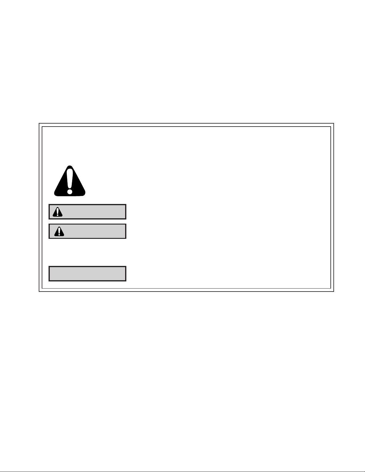
This is a safety Alert symbol.
This symbol alerts you to potential hazards that can kill or hurt you and others.
All safety messages will follow the safety alert symbol with the word “WARNING”
or “CAUTION”. These words mean:
You can be killed or seriously injured if you do not follow instructions.
You can receive minor or moderate injury if you do not follow instructions.
A message to alert you of potential property damage will have the
word “NOTICE”. Potential property damage can occur if instructions
are not followed.
WARNING
CAUTION
NOTICE
2

Do not spray or pour water on the return air grille, discharge air grille, evaporator coil, control panel, •
and sleeve on the room side of the air conditioning unit while cleaning.
Electrical component malfunction caused by water could result in electric shock or other electrically •
unsafe conditions when the power is restored and the unit is turned on, even after the exterior is dry.
Never operate the A/C unit with wet hands.•
Use air conditioner on a single dedicated circuit within the specied amperage rating. •
Use on a properly grounded outlet only.•
Do not remove ground prong of plug.•
Do not cut or modify the power supply cord.•
Do not use extension cords with the unit.•
Follow all safety precautions and use proper and adequate protective safety aids such as: gloves, •
goggles, clothing, adequately insulated tools, and testing equipment etc.
Failure to follow proper safety procedures and/or these warnings can result in serious injury or death. •
REFRIGERATION SYSTEM HAZARDS:
Use approved standard refrigerant recovering procedures and equipment to relieve pressure before •
opening system for repair.
Do not allow liquid refrigerant to contact skin. Direct contact with liquid refrigerant can result in minor •
to moderate injury.
Be extremely careful when using an oxy-acetylene torch. Direct contact with the torch’s ame or hot •
surfaces can cause serious burns.
Make sure to protect personal and surrounding property with re proof materials.•
Have a re extinguisher at hand while using a torch.•
Provide adequate ventilation to vent off toxic fumes, and work with a qualied assistant whenever •
possible.
Always use a pressure regulator when using dry nitrogen to test the sealed refrigeration system for •
leaks, ushing etc.
Make sure to follow all safety precautions and to use proper protective safety aids such as: gloves, •
safety glasses, clothing etc.
Failure to follow proper safety procedures and/or these warnings can result in serious injury or death. •
MECHANICAL HAZARDS:
Extreme care, proper judgment and all safety procedures must be followed when testing, •
troubleshooting, handling, or working around unit with moving and/or rotating parts.
Be careful when, handling and working around exposed edges and corners of sleeve, chassis, and •
other unit components especially the sharp ns of the indoor and outdoor coils.
Use proper and adequate protective aids such as: gloves, clothing, safety glasses etc.•
Failure to follow proper safety procedures and/or these warnings can result in serious injury or death.•
3
4
PROPERTY DAMAGE HAZARDS
FIRE DAMAGE HAZARDS:
Read the Installation/Operation Manual for this air conditioning unit prior to operating.•
Use air conditioner on a single dedicated circuit within the specied amperage rating. •
Connect to a properly grounded outlet only.•
Do not remove ground prong of plug.•
Do not cut or modify the power supply cord.•
Do not use extension cords with the unit.•
Failure to follow these instructions can result in re and minor to serious property damage.•
WATER DAMAGE HAZARDS:
Improper installation maintenance, or servicing of the air conditioner unit, or not following the above •
Safety Warnings can result in water damage to personal items or property.
Insure that the unit has a sufcient pitch to the outside to allow water to drain from the unit. •
Do not drill holes in the bottom of the drain pan or the underside of the unit. •
Failure to follow these instructions can result in result in damage to the unit and/or minor to serious •
property damage.
INTRODUCTION
This service manual is designed to be used in conjunction with the installation manuals provided with each unit.
This service manual was written to assist the professional HVAC service technician to quickly and accurately
diagnose and repair any malfunctions of this product.
This manual, therefore, will deal with all subjects in a general nature. (i.e. All text will pertain to all models).
IMPORTANT:
It will be necessary for you to accurately identify the unit you are
servicing, so you can be certain of a proper diagnosis and repair.
(See Unit Identication.)
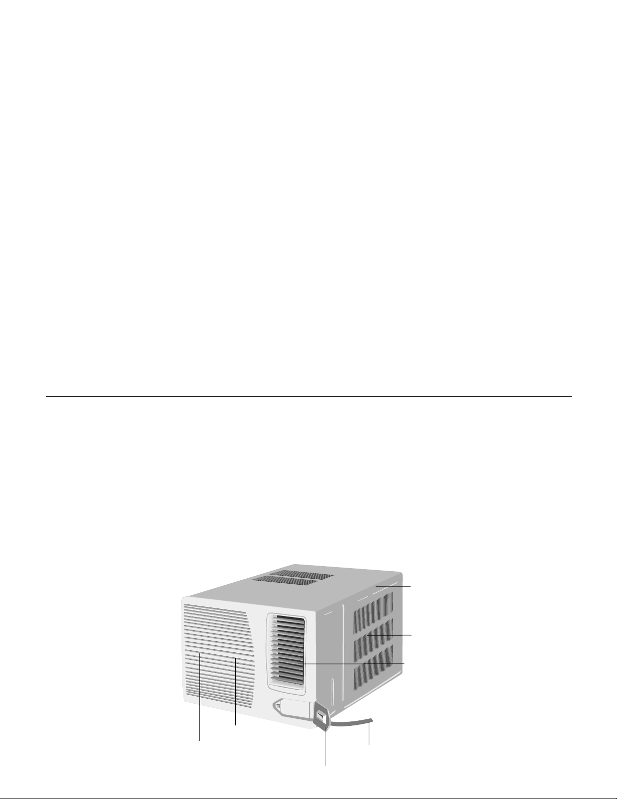
Cabinet
Airinlet louver
Front grille
Powercord
Control panelcover
Frontintakegrille
Airfilter
(behindfront intake grille)
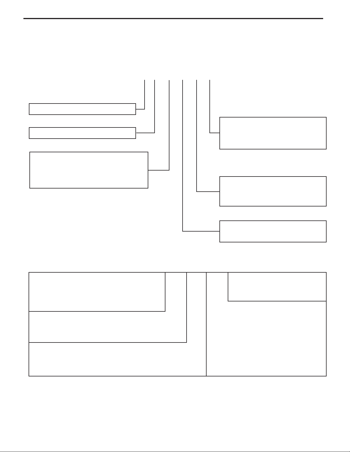
Serial Number
Decade Manufactured
L=0 C=3 F=6 J=9
A=1 D=4 G=7
B=2 E=5 H=8
L H G K 00001
Production Run Number
Year Manufactured
A=1 D=4 G=7 K=0
B=2 E=5 H=8
C=3 F=6 J=9
Product Line
K = RAC
Month Manufactured
A=Jan D=Apr G=Jul K=Oct
B=Feb E=May H=Aug L=Nov
C=Mar F=Jun J=Sept M=Dec
3rd and 4th Digit - Approximate
BTU/HR (Cooling)
Heating BTU/Hr capacity listed in the
Specication/Performance Data Section
7th Digit – Options
0 = Straight Cool &
Heat Pump Models
6th Digit – Voltage
1 = 115 Volts
3 = 230-208 Volts
5th Digit
Alphabetical Modier
COMPACT
PROGRAMMABLE
Model Number Code
C P 08 E 1 0
RAC Serial Number Identication Guide
UNIT IDENTIFICATION
5
ELECTRICAL DATA
ELECTRIC SHOCK HAZARD
WARNING
Turn off electric power before service or
installation.
All electrical connections and wiring MUST be
installed by a qualied electrician and conform to
the National Electrical Code and all local codes
which have jurisdiction.
Failure to do so can result in personal injury or
death.
Not following the above WARNING could result in re or
electically unsafe conditions which could cause moderate
or serious property damage.
Read, understand and follow the above warning.
NOTICE
FIRE HAZARD
Wire Size Use ONLY wiring size recommended for single outlet branch circuit.
Fuse/Circuit Breaker Use ONLY the correct HACR type and size fuse/circuit breaker. Read electrical ratings on unit’s
rating plate. Proper circuit protection is the responsibiity of the homeowner.
Grounding Unit MUST be grounded from branch circuit through service cord to unit, or through separate
ground wire provided on permanently connected units. Be sure that branch circuit or general
purpose outlet is grounded. Ground wire must be connected to ground screw located in lower
right corner of air conditioner when air conditioner is in cabinet. (CP 14, 18, 24)
Receptacle The eld supplied outlet must match plug on service cord and be within reach of service cord.
Do NOT alter the service cord or plug. Do NOT use an extension cord. Refer to the table above
for proper receptacle and fuse type.
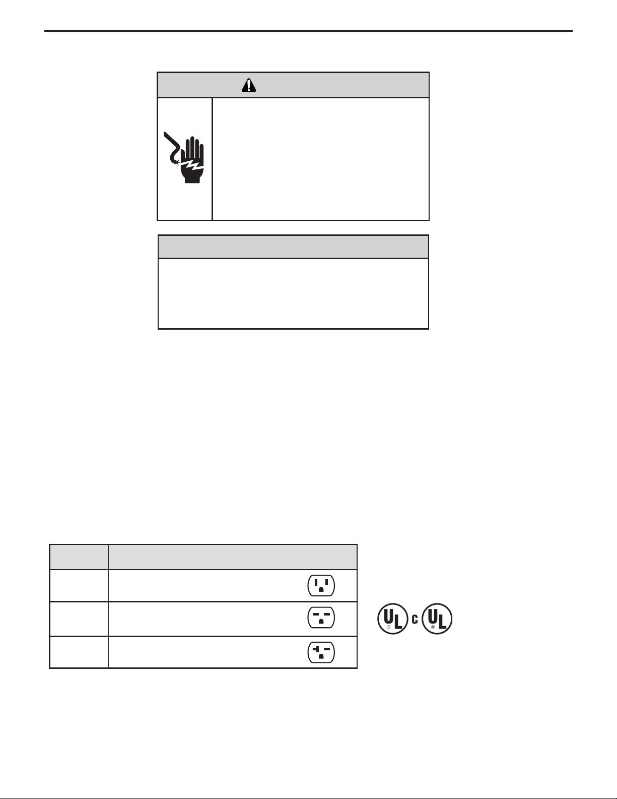
Plug/Outlet/Circuit Rating
Model
Circuit Rating
Breaker or T-D Fuse
Plug Face
(NEMA#)
Power Cord
Length (ft.)
Wall Outlet
Appearance
CP14 125V - 15A 5 - 15P 6
CP18 250V - 15A 6 - 15P 4
CP24 250V - 20A 6 - 20P 4
6
7
ELECTRICAL SHOCK HAZARD
WARNING
Plug into a grounded 3 prong outlet.
Do not remove powercord ground prong.
Do not use a plug adapter.
Do not use an extension cord.
Failure to follow these instructions can
result in death, re, or electrical shock.
This air conditioner must be grounded. This air conditioner
is equipped with a power supply cord having a grounded 3
prong plug. To minimize possible shock hazard, the cord
must be plugged into a mating, grounded 3 prong outlet,
grounded in accordance with all local codes and ordinances.
If a mating outlet is not available, it is the customer’s
responsibility to have a properly grounded 3 prong outlet
installed by a qualied electrical component installer.
It is the customer’s responsibility:
To contact a qualied electrical installer, and to assure
that the electrical installation is adequate and in
conformance with National Electrical Code, ANSI/NFPA
70 - latest edition, and all local codes and ordinances.
Copies of the standards listed may be obtained from:
National Fire Protection Association
One Batterymarch Park
Quincy, MA 02269
Recommended grounding method
To test your power supply cord:
1. Plug power supply cord into a grounded 3 prong outlet.
2. Press RESET.
3. Press TEST (listen for click; Reset button will trip and
pop out).
4. Press and release RESET (listen for click; Reset butto
will latch and remain in). The power supply cord is ready
for operation.
NOTES:
The Reset button must be pushed in for proper
operation.
The power supply cord must be replaced if it fails to trip
when the test button is pressed or if it fails to reset.
Do not use the power supply cord as an off/on switch.
The power supply cord is designed as a protective
device.
A damaged power supply cord must be replaced with
a new power supply cord obtained from the product
manufacturer and must not be repaired.
The power supply cord contains no user serviceable
parts. Opening the tamper-resistant case voids all
warranty and performance claims.
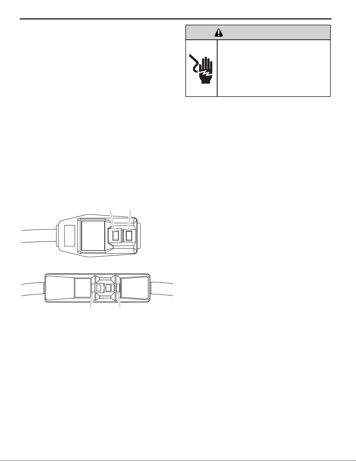
Power Supply Cord
NOTE: Your unit’s device may differ from the ones shown.
A. Reset button
B. Test button
This room air conditioner is equipped with a power supply
cord required by UL. This power supply cord contains
state-of-the-art electronics that sense leakage current. If
the cord is crushed, the electronics detect leakage current
and power will be disconnected in a fraction of a second.
TEST
TEST
RESET
RESET
A
A
B
B
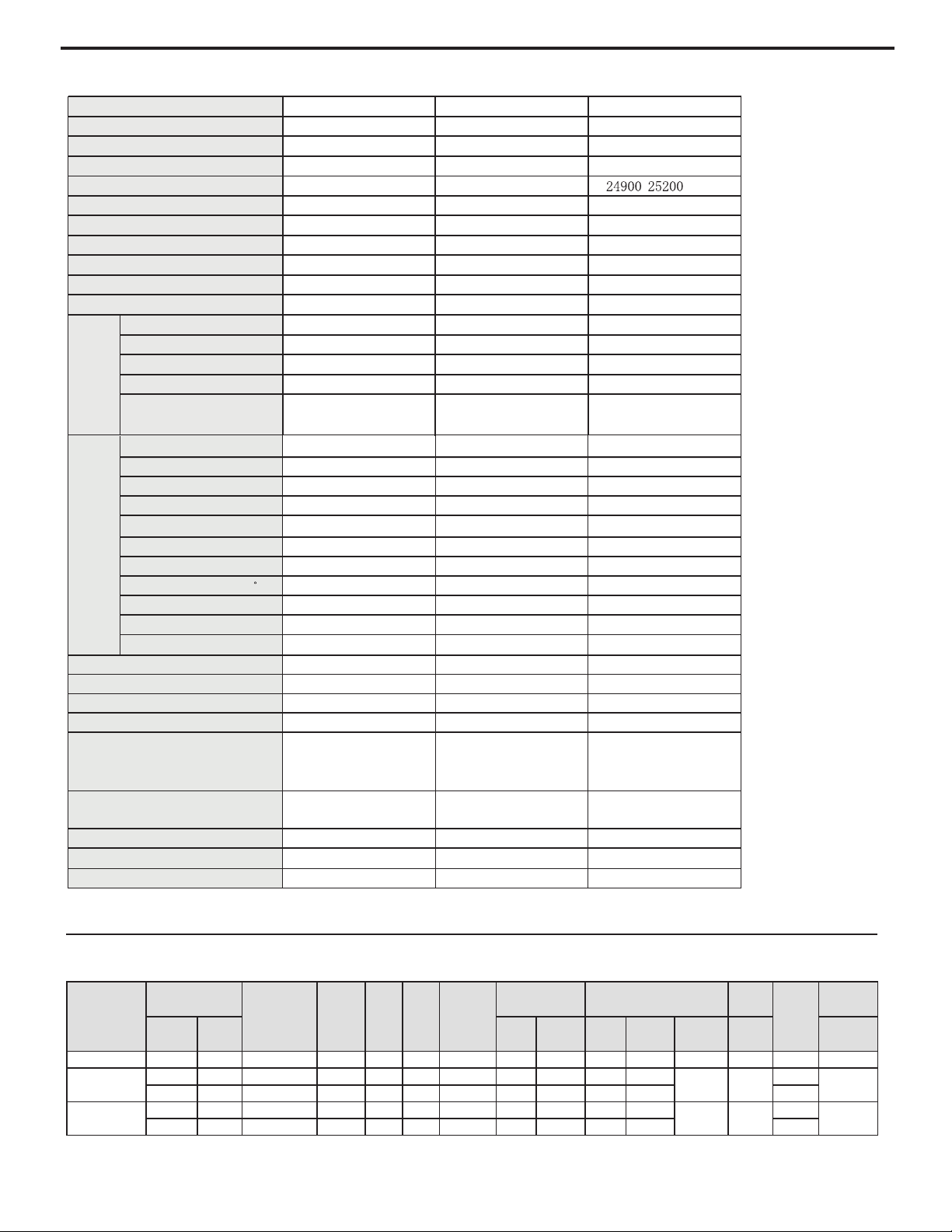
SPECIFICATIONS FOR 2009 MODELS
8
Performance Data
PERFORMANCE
DATA* Cooling
EVAP. AIR TEMP.
DEG. F
CONDENSER
TEMPERATURE
DEG. F
Discharge
Temp
Suction
Temp
Super
Heat
Sub-Cooling
OPERATING
PRESSURES
ELECTRICAL RATINGS R-22 REF.
Voltage
BREAKER
FUSE
Discharge
Air
Temp.
Drop F.
Suction Discharge
Amps
Cool
Amps
Heat
Locked
Rotor Amps
Charge in
OZ.
60 Hertz
Amps
CP14N10
59 21 118 173 56 41 54 78 267 12.1 / 58 26.5 115 15
CP18N30
58 22 119 173 66 52 55 77 269 8.3 /
38.9/42.4 27.9
230
15
802/5.8 962 775525 66 271 911 32 75
CP24N30
57 23 117 197 60 44 50 75 264 12.3 /
56A(230V) 33.5
230
20
802/1.31 462 570544 75 591 711 42 65
*Rating Conditions: 80 degrees F, room air temp. & 50% relative humidity, with 95 degree F, outside air temp & 40% relative humidity.
Compressor Type
Rotary Rotary Rotary
L.R.A. (A)
61 42 60
Compressor RLA(A)
11.5 11.2/10.7
Compressor Power Input(W)
1060
2310/2390
Overload Protector
InternalExternal Internal
Throttling Method
Capillary Capillary Capillary
Starting Method Capacitor Capacitor Capacitor
Working Temp Range (
F
)
50°-115° 50°-115° 50°-115°
Condenser
Aluminum fin-copper tube Aluminum fin-copper tube Aluminum fin-copper tube
Fan Type-Piece
Axial fan –1 Axial fan –1 Axial fan –1
F
an Diameter (inches)
15.59 15.59 15.59
900/780/730 1000/900/800 1060/970/820
205 297 320
1.78 1.29 1.39
15 7 7
300 300 300
150 150 150
17
½
X 26 X 27
⅝
17
½
X 26 X 29
¾
17
½
X 26 X 29
¾
121 141 165
R22/28.57 R22/32.10 R22/37.04
Outdoor
Side
Fan Motor Speed (rpm) (H/M/L)
Output of Fan Motor (W)
Fan Motor RLA(A)
Fan Motor Capacitor (uF)
Net
Weight
Refrigerant Charge (oz)
Permissible Excessive Operating
Pressure for the Discharge
Side(PSI)
Permissible Excessive Operating
Pressure for the Suction Side(PSI)
Dimension (W/H/D)
7.5
1606
CP14E10 CP18E30 CP24E30
COOLING
COOLING
COOLING
115V 208~230V 208~230V
60Hz 60Hz 60Hz
14700(Btu/h) 18000 /18450(Btu/h)
/ (Btu/h)
1370 1680/1730 2660/2690
1757W 2259W 3295W
17.61A 9.02A 15A
798/730/696 968/918/866 1002/950/866
5.28 5.92 9.93
10.8 10.8 / 10.8 9.4 / 9.4
Fan Type-Piece Centrifugal flow fan – 1 Centrifugal flow fan – 1 Centrifugal flow fan – 1
Diameter-Length (inch) 8.82 X 4.31 8.82 X 4.31 8.82 X 4.31
Evaporator Alum inum fin-copper tube Aluminum fin-copper tube Aluminum fin-copper tube
Pipe Diameter (inches)
.276 .276 .276
Coil length (l) x height (H) x
coil width (L)
422 X 381 X 25.4 422 X 381 X 25.4 422 X 381 X 25.4
Model
Function
Rated Voltage
Rated Input (W)
Rated Current (A)
Air Flow Volume
(CFM) (H/M/L)
Rated Frequency
Total Capacity (W/
Btu/h)
Power Input (W)
Indoor
Side
Dehumidifying Volume (pints/h)
EER
PERFORMANCE
DATA* Cooling
EVAP. AIR TEMP.
DEG. F
CONDENSER
TEMPERATURE
DEG. F
Discharge
Temp
Suction
Temp
Super
Heat
Sub-Cooling
OPERATING
PRESSURES
ELECTRICAL RATINGS R-22 REF.
Voltage
BREAKER
FUSE
Discharge
Air
Temp.
Drop F.
Suction Discharge
Amps
Cool
Amps
Heat
Locked
Rotor Amps
Charge in
OZ.
60 Hertz
Amps
CP14N10
59 21 118 173 56 41 54 78 267 12.1 / 58 26.5 115 15
CP18N30
58 22 119 173 66 52 55 77 269 8.3 /
38.9/42.4 27.9
230
15
802/5.8 962 775525 66 271 911 32 75
CP24N30
57 23 117 197 60 44 50 75 264 12.3 /
56A(230V) 33.5
230
20
802/1.31 462 570544 75 591 711 42 65
*Rating Conditions: 80 degrees F, room air temp. & 50% relative humidity, with 95 degree F, outside air temp & 40% relative humidity.
Compressor Type
Rotary Rotary Rotary
L.R.A. (A)
58 42 56
Compressor RLA(A)
10.9 11.7/11.0
Compressor Power Input(W)
1182
2425/2480
Overload Protector
ExternalExternal Internal
Throttling Method
Capillary Capillary Capillary
Starting Method Capacitor Capacitor Capacitor
Working Temp Range (
F
)
50°-115° 50°-115° 50°-115°
Condenser
Aluminum fin-copper tube Aluminum fin-copper tube Aluminum fin-copper tube
Fan Type-Piece
Axial fan –1 Axial fan –1 Axial fan –1
F
an Diameter (inches)
15.59 15.59 15.59
900/780/730
900/780/730 1000/900/800
200 200 190
3 1.45 1.35
15 7 7
300 300 300
150 150 150
17
½
X 26 X 27
⅝
17
½
X 26 X 27
⅝
17
½
X 26 X 29
¾
121 141 165
R22/26.46 R22/27.87 R22/33.51
Outdoor
Side
Fan Motor Speed (rpm) (H/M/L)
Output of Fan Motor (W)
Fan Motor RLA(A)
Fan Motor Capacitor (uF)
Net
Weight
Refrigerant Charge (oz)
Permissible Excessive Operating
Pressure for the Discharge
Side(PSI)
Permissible Excessive Operating
Pressure for the Suction Side(PSI)
Dimension (W/H/D)
7.45
1700
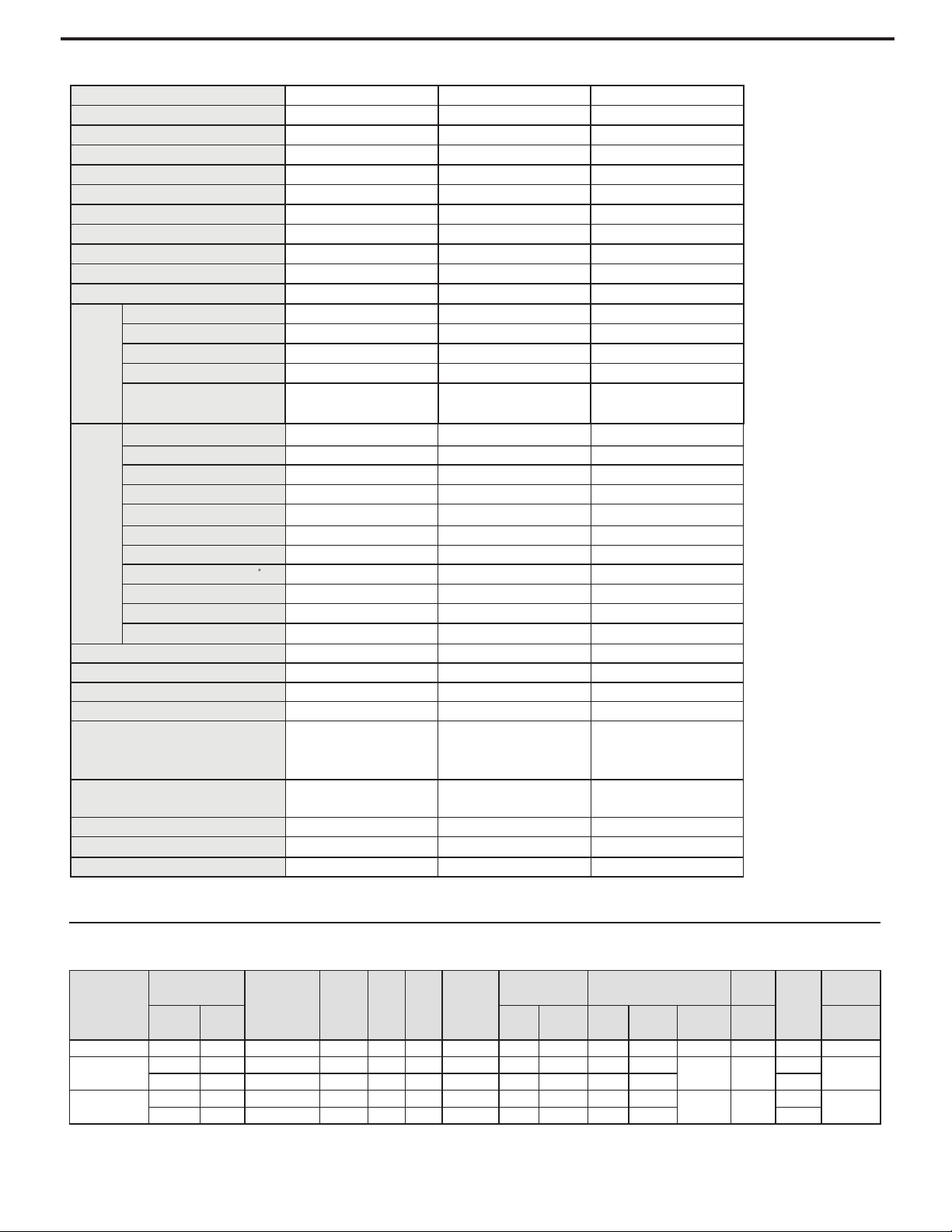
CP14N10 CP18N30 CP24N30
COOLING
COOLING
COOLING
115V 230V/208V~ 230V/208V~
60Hz 60Hz 60Hz
14000(Btu/h) 18000 /17600(Btu/h) 23500/23100(Btu/h)
1430 1850/1810 2740/2710
1540W 2478W 3538W
15A 12.57A 18.09A
458.8 458.8 617.6
3.38 4.65 8.46
9.8 9.7 / 9.7 8.6 / 8.5
Fan Type-Piece Centrifugal flow fan – 1 Centrifugal flow fan – 1 Centrifugal flow fan – 1
Diameter-Length (inch) 7.93 X 4.31 7.93 X 4.31 8.82 X 4.31
Evaporator Alum inum fin-copper tube Aluminum fin-copper tube Aluminum fin-copper tube
Pipe Diameter (inches)
0.276 0.276 0.276
Coil length (l) x height (H) x
coil width (L)
16.61 X 15 X 1 16.61 X 15 X 1 16.61 X 15 X 1
Model
Function
Rated Voltage
Rated Input (W)
Rated Current (A)
Air Flow Volume
(CFM) (H/M/L)
Rated Frequency
Total Capacity (W/Btu/h)
Power Input (W)
Indoor
Side
Dehumidifying Volume (pints/h)
EER
9
SPECIFICATIONS FOR 2008 MODELS
Performance Data

10
COMPONENT DEFINITIONS
A. Mechanical components
B. Electrical components
C. Hermetic components
Vent door
Exhausts stale room air outside.
Plenum assembly
Diffuser with directional louvers used to direct the conditioned airow.
Blower wheel
Attaches to the indoor side of the fan motor shaft and is used for distributing unconditioned, room side air through
the heat exchanger and delivering conditioned air into the room.
Slinger fan blade
Attaches to the outdoor side of the fan motor shaft and is used to move outside air through the condenser coil, while
slinging condensate water out of the base pan and onto the condenser coil, thus lowering the temperature and
pressures within the coil.
Thermistor
A sensor that automatically responds to temperature changes.
Capacitor
Reduces line current and steadies the voltage supply, while greatly improving the torque characteristics of the fan
motor and compressor motor.
MoneySaver® switch
Used to regulate the operation of the fan motor and the compressor or to turn the unit off. For troubleshooting, refer
to the wiring diagrams and schematics in the back of this service manual.
Fan Motor
Dual-shafted fan motor operates the indoor blower wheel and the condenser fan blade simultaneously.
Compressor
Motorized device used to compress refrigerant through the sealed system.
Capillary tube
A cylindrical meter device used to evenly distribute the ow of refrigerant to the heat exchangers (coils).
AIR CONDITIONER USE
Operating the air conditioner properly helps you to obtain
the best possible results.
This section explains proper air conditioner operation.
IMPORTANT:
If you turn off the air conditioner, wait at least 3 minutes
before turning it back on. This prevents the air conditioner
from blowing a fuse or tripping a circuit breaker.
Do not try to operate your air conditioner in the cool-
ing mode when outside temperature is below 65°F
(18°C). The inside evaporator coil will freeze up, and
the air conditioner will not operate properly.
NOTE: In the event of a power failure, your air condi-
tioner will operate at the previous settings when the
power is restored.
11
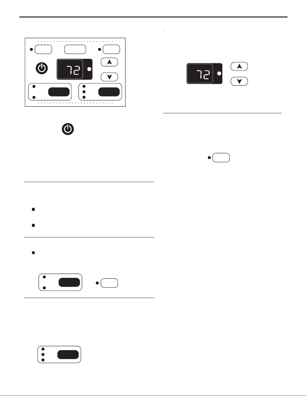
1. Press POWER to turn on air conditioner.
NOTE: When the unit is turned on, it will display the previous
settings for the Mode, Fan Speed and temperature.
2. Choose mode. See “Mode .”
3. Choose fan speed. See “ Fan Speed.”
4. Choose temperature. See “Temperature.”
Mode
1. Press and hold MODE.
2.
Cool—Cools room. Press FAN SPEED to choose fan
speed. Then adjust the temperature by pressing the up or
down arrow buttons.
Fan—Operates the fan at High sp eed, without cooling.
The display shows “FO” (fan only).
Fan Speed
NOTE: The Fan Speed button will operate only when the Cool or
Power Saver mode ha s been selected.
1. Press and hold FAN SPEED until you see the indicator light
for the desired setting.
2. Choose High, Medium or Low.
Temperature
Press, or press and hold, the plus button to raise the
temperature 1º until it reaches 86ºF (30ºC).
Press, or press and hold, the minus button to lower the
temperature 1º until it reaches 64ºF (18ºC).
Timer Delay
To set the Timer for a 1- to 24-hour delay until the air
conditioner turns o (the air conditioner must be On):
1. Press TIMER. Indicator light will ash.
2. Press the plus or minus button to change the delay time from
1 to 24 hours.
3. Press TIMER or wait 10 seconds. Indicator light will remain
on.
To set the Timer delay for a 1- to 24-hour delay until the air
conditioner turns on, keeping previous settings:
1. Turn o air conditioner.
2. Press TIMER. Indicator light wi
ll ash.
3. Press the plus or minus button to change the delay time from
1 to 24 hours.
4. Press TIMER or wait 10 seconds. Indicator light will remain
on.
To set the Timer delay for a 1- to 24-hour delay until the air
conditioner turns on, changing previous settings:
1. Turn on air conditioner.
2. Adjust MODE to desired setting.
3. Adjust FAN SPEEDto High, Medium or Low.
4. Adjust temperature between 64ºF (18ºC) and 86ºF (30ºC).
5. Turn o air conditioner.
6. Press TIMER. Indicator light will ash.
7. Press the plus or minus button to change delay time from 1 to
24 hours.
8. Press TIMER or wait 10 seconds.
To clear Timer delay program
NOTE: Air conditioner can be either on or o.
Press and hold TIMER for 3 seconds. Indicator light will turn o.
To see the time remaining (in hours)
1. Press TIMER once after it has been set.
2. While the display is showing the remaining time, you can
press the plus or minus button to increase or decrease the
time.
POWER
Temp/Hour
Timer
Fan Speed
Fan Only
Cool
Money
Saver
®
High
Med
Low
0
F
Mode
Hr.
Auto Swing
Temp/Hour
0
F
Hr.
Timer
Money Saver — Turns fan to low speed when
room temperature reaches the temperature setting
on the thermostat.
Fan Only
Cool
Mode
Money
Saver
®
Fan Speed
High
Med
Low
POWER
Money Saver
®
Choose Cool or Fan mode
How to operate the Friedrich room air conditioner
12
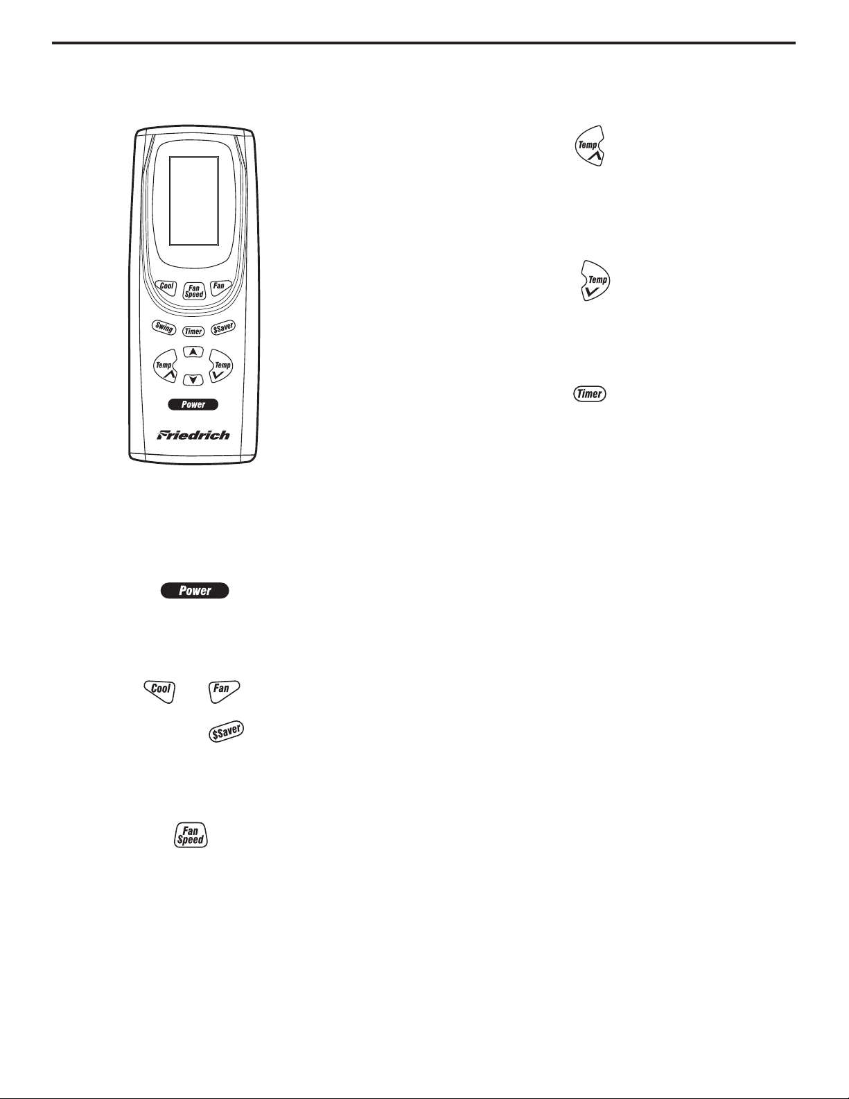
To operate air conditioner with remote control
NOTE: Remote control may vary in appearance.
NOTE: Two AAA batteries (included) power the remote control.
Replace batteries after 6 months of use, or when the remote
control starts to lose power.
To turn the air conditioner on or o:
Press POWER.
To select the mode:
To select the fan speed:
Press FAN SPEED for High, Medium or Low.
To raise the temperature:
Press the plus button to raise the temperature. Each time you
press or hold
the plus button, the temperature will go up 1º until it
reaches 86°F (30°C).
To lower the temperature:
Press the minus button to lower the temperature. Each time you
press or hold the minus butto n, the temperature will go down 1º
until it reaches 64°F (18°C).
To set Timer for a 1- to 24-hour delay before air conditioner
is turned o (air conditioner must be On):
1. Press TIMER. Indicator light on air conditioner control panel
will ash.
2. Press the plus or minus b
utton to change the delay time from
1 to 24 hours.
3. Press TIMER again or wait 10 seconds. Indicat or light on air
conditioner control panel will remain on.
To set Timer to turn on air conditioner, keeping previous
settings:
1. Turn o air conditioner.
2. Press TIMER. Indicator light on air conditioner control panel
will ash.
3. Press the plus or minus button to change delay time (1 to
24 hours).
4. Press TIMER again or wait 10 seconds. Indicat or light on air
conditioner control panel will remain on.
To set Timer to turn on air conditioner, changing the
previous settings:
1. Turn on air conditioner.
2. Adjust Mode to Cool, Fan Only, or Power Saver.
3. Adjust Fan Speed to High, Medium or Low.
4. Adjust temperature between 64°F (18ºC) and 86°F (30ºC).
5. Turn o air conditioner.
6. Press TIMER. Indicator light on air conditioner control panel
will ash.
7. Press the plus or minus button to change delay time (1 to
24 hours).
8. Press TIMER again or
wait 10 seconds. Indicator light on air
conditioner control panel will remain on.
Press COOL, FAN or $ SAVER
 Loading...