


CP10G10B
0
F
Power
Mode
Timer
0
n
/0ff
Fan
Speed
Temp
CoolMoney
Saver
®
Fan
Only
Dry
hr
Auto
Swing
0
F
Power
Mode
Timer
0
n
/0ff
Fan
Speed
Temp
CoolMoney
Saver
®
Fan
Only
Dry
hr
Auto
Swing
230
CP15
CP18
CP24
115
16

For inner cleaning, contact an Authorized Service Center or a dealer.
Do not use harsh detergent that causes corrosion or damage on the unit.
Harsh detergent may also cause failure of product, fire, or electronic shock.
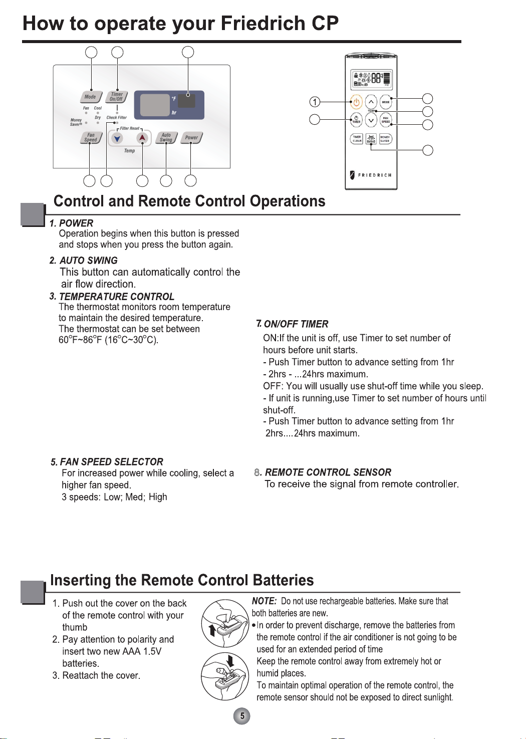
Check Filter: Your ‘Check Filter’ LED will
light up after approximately 250 hours of
operation, notifying you that your filter needs
to be cleaned.
*Timer Clear: On remote control, ‘Timer Clear’ button
will cancel the timer setting
8
2
1
3
4
5
6
7
8
3
2
5
6
7
Filter Reset: press ‘Temp ∨∧’ together to
turn off ‘Check Filter’ light.
*Filter Reset must be done from unit control
panel, not remote control
Push the ‘Mode’ button to rotate between
MoneySaver → Cool → Fan → Dry modes.
(select Dry mode for dry/dehumidifier
operation)
MoneySaver: The fan will stop when the compressor
stops cooling. The fan will turn on approximately
every 3 minutes to sample to room air and determine
if more cooling is needed.
Cool: fan runs continually for normal cooling operation
Fan Only: Fan-only operation
*MoneySaver has it’s own button on your remote
control
4. CHECK FILTER & FILTER RESET
6. OPERATION MODE SELECTOR

41
8
26
41
18
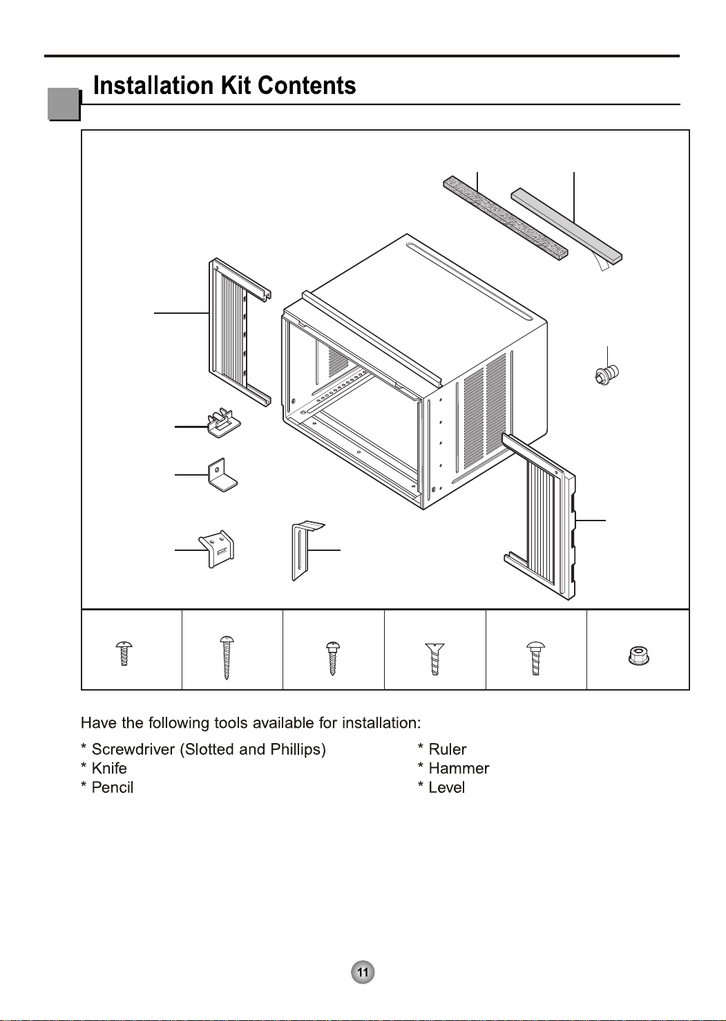
Foam-PE
(Adhesive-Backed)
Type C (5) Type D (2)
Type A (11)
Carriage Bolt (2) Lock Nut (4)
Type B (7)
Foam strip
(Plain-Back)
Right frame
curtain
Window locking
bracket
Left frame
curtain
Frame guide(2)
Sill
bracket
(2)
Support bracket(2)
Drain joint pipe
4
4
4
10
3
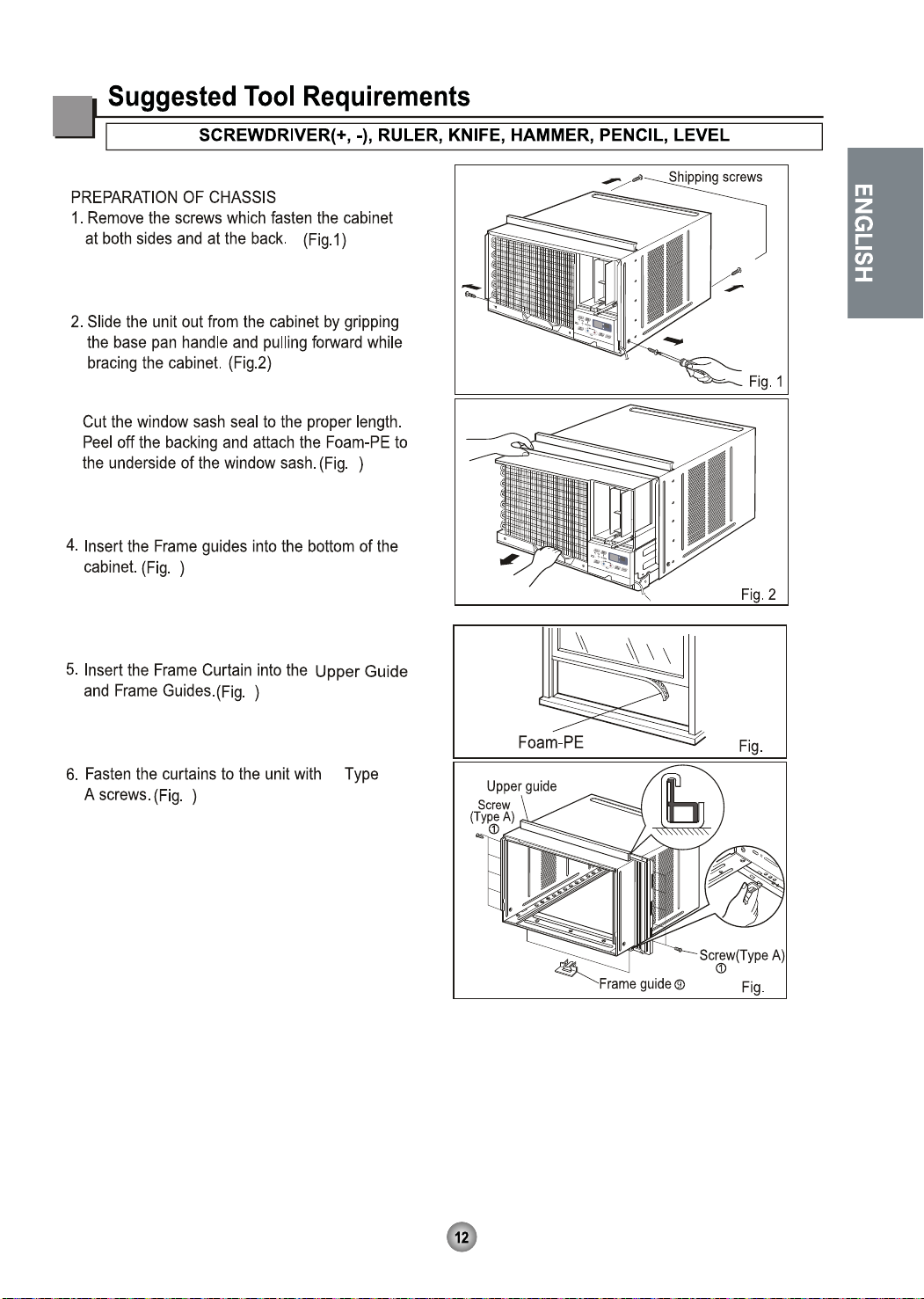
3.
3
44
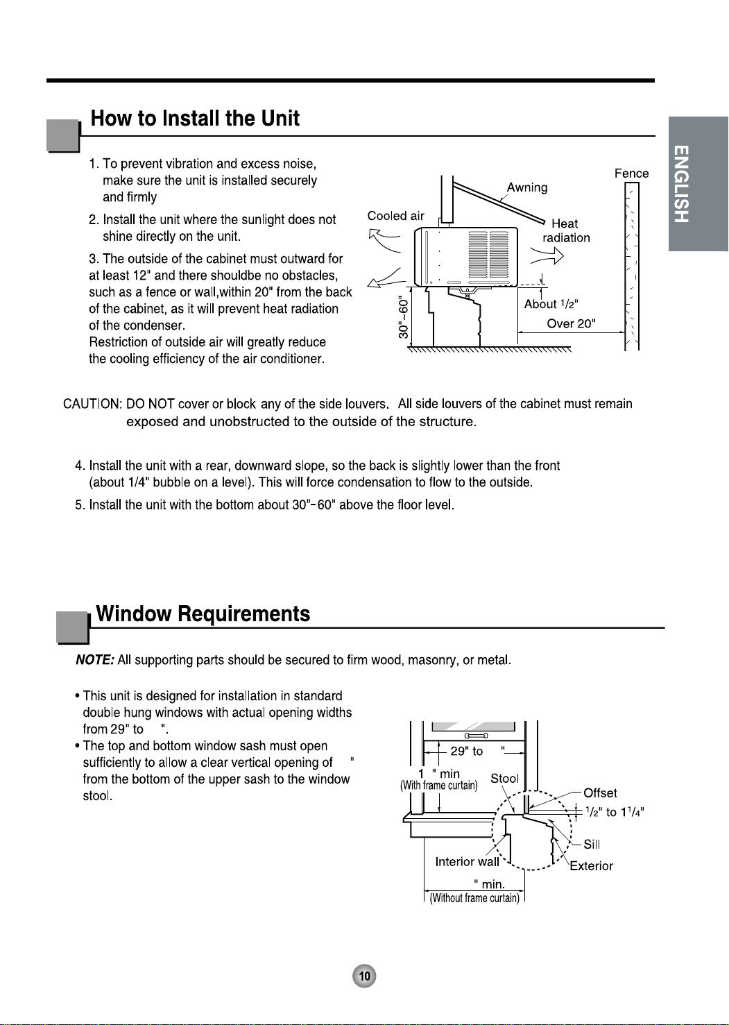
1. Open the window. Mark a line on the center of
the window stool between the side window stop
moldings.
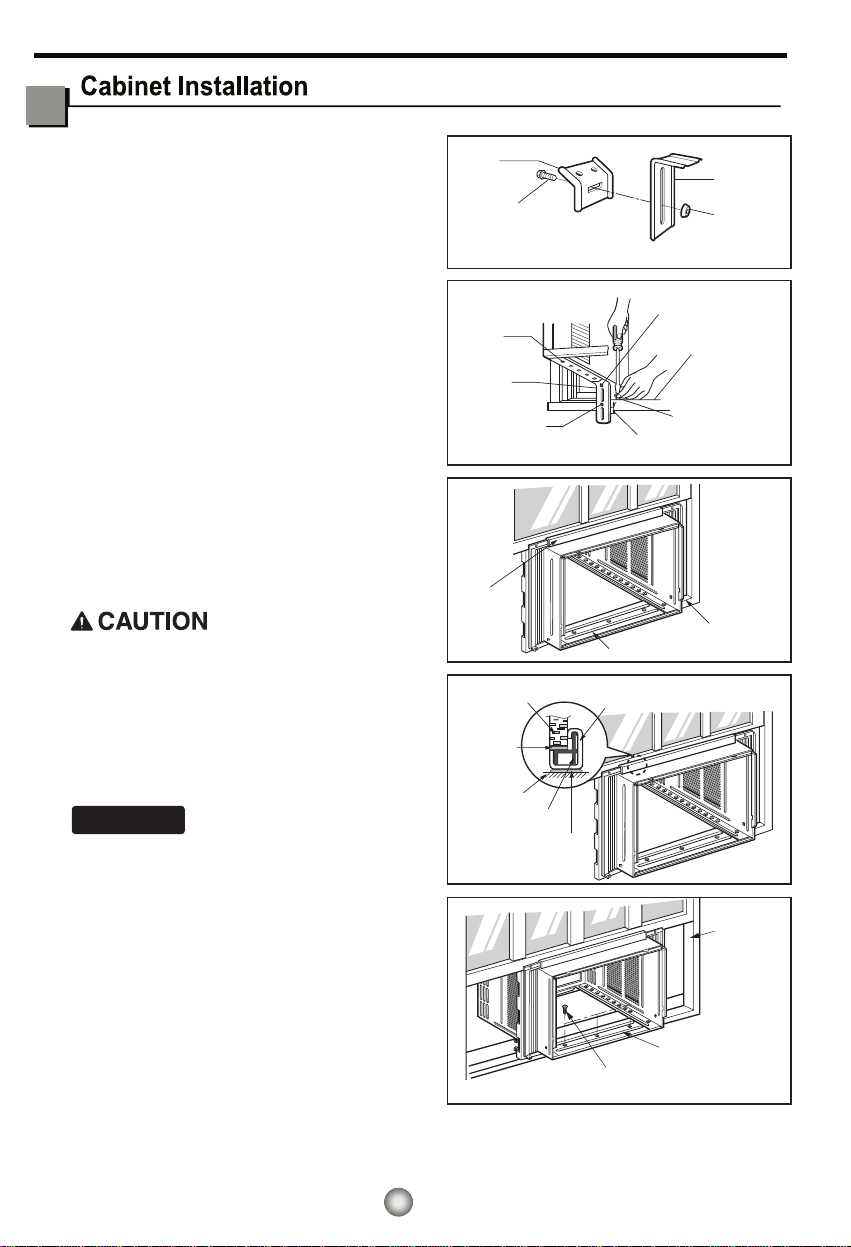
Loosely attach the sill bracket to the support
bracket using the carriage bolt and the lock nut.
2. Attach the sill bracket to the window sill using
the screws (Type B).
Carefully place the cabinet on the window stool
and align the center mark on the bottom front
with the center line marked window stool.
3. Using the M-screw and the lock nut, attach the
support bracket to the cabinet track hole. Use
the first track hole after the sill bracket on the
outer edge of the window sill. Tighten the
carriage bolt and the lock nut. Be sure the
cabinet slants outward.
Do not drill a hole in the bottom pan. The unit is
designed to operate with approximately 1/2" of
water in bottom pan.
4. Pull the bottom window sash down behind the
Top retainer bar until they meet.
1. Do not
pull the window sash down so tightly
that the movement of Frame curtain is
restricted. Attach the cabinet to the window
stool by driving the screws (Type B) through
the cabinet into window stool.
2.The cabinet should be installed with a very
slight tilt downward toward the outside.
NOTICE
Support
Bracket
Lock nut
Sill
Bracket
Carriage
Bolt
(M-Screw)
Front angle
Window stool
Window sash
Top retainer bar
Cabinet
Foam-PE
Frame curtain
Screw(Type B)
Front Angle
Sash track
Foam-PE
Cabinet
Track hole
Support
Bracket
Carriage bolt
and lock nut
Machine screw(Type D)
and lock nut
Outer edge
of window
sill
Screw(Type B)
Sill bracket
Top
retainer
bar
Fig. 5
Fig. 6
Fig. 7
Fig. 8
Fig. 9
13
ENGLISH
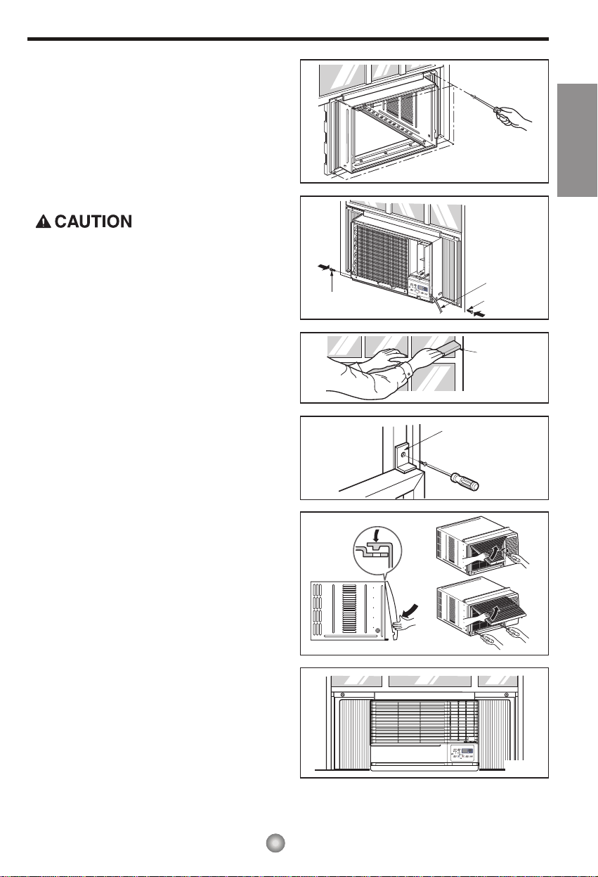
5.
Pull each Frame curtain fully to each window sash
track, and pull the bottom window sash down behind
the Top retainer bar until it meets.
6.
Attach each Frame curtain the window sash by
using screws (Type C.) (See Fig. 10)
7.
Slide the unit into the cabinet.(See Fig. 11)
For security purpose, reinstall screws(Type A) at
cabinet's sides.
8.
Cut the Foam-strip to the proper length and insert
between the upper window sash and the lower
window sash.(See Fig. 12)
9.
Attach the Window locking bracket with a screw
(Type C.) (See Fig. 13)
10.
Attach the front grille to the cabinet by inserting the
tabs on the grille into the tabs on the front of the
cabinet. Push the grille in until it snaps into
place.(See Fig.14)
Lift the inlet grille and secure it with a screw (Type
A) through the front grille.(See Fig. 14)
Window installation of room air conditioner is now
completed. See ELECTRICAL DATA for attaching
power cord
to electrical outlet.
Power Cord
Screw (Type A)
Screw
Window locking
bracket
Foam-Strip
Screw(Type C)
Fig. 10
Fig. 11
Fig. 12
Fig. 13
Fig. 14
Fig. 15
3.
4.
14

15

16
 Loading...