

Flintec DAS 72.1 Mark III User Manual
Process Indicator Type DAS 72.1 Mark III
MANUAL
Firmware Version 72.181.v.4.28 or higher
Hardware Version 72.101.5.v.3.0x
Document No G128 Rev6 GB
Manual DAS 72.1 Page 1
www.flintec.com

A GENERAL
A.1 INTRODUCTION AND SPECIFICATION
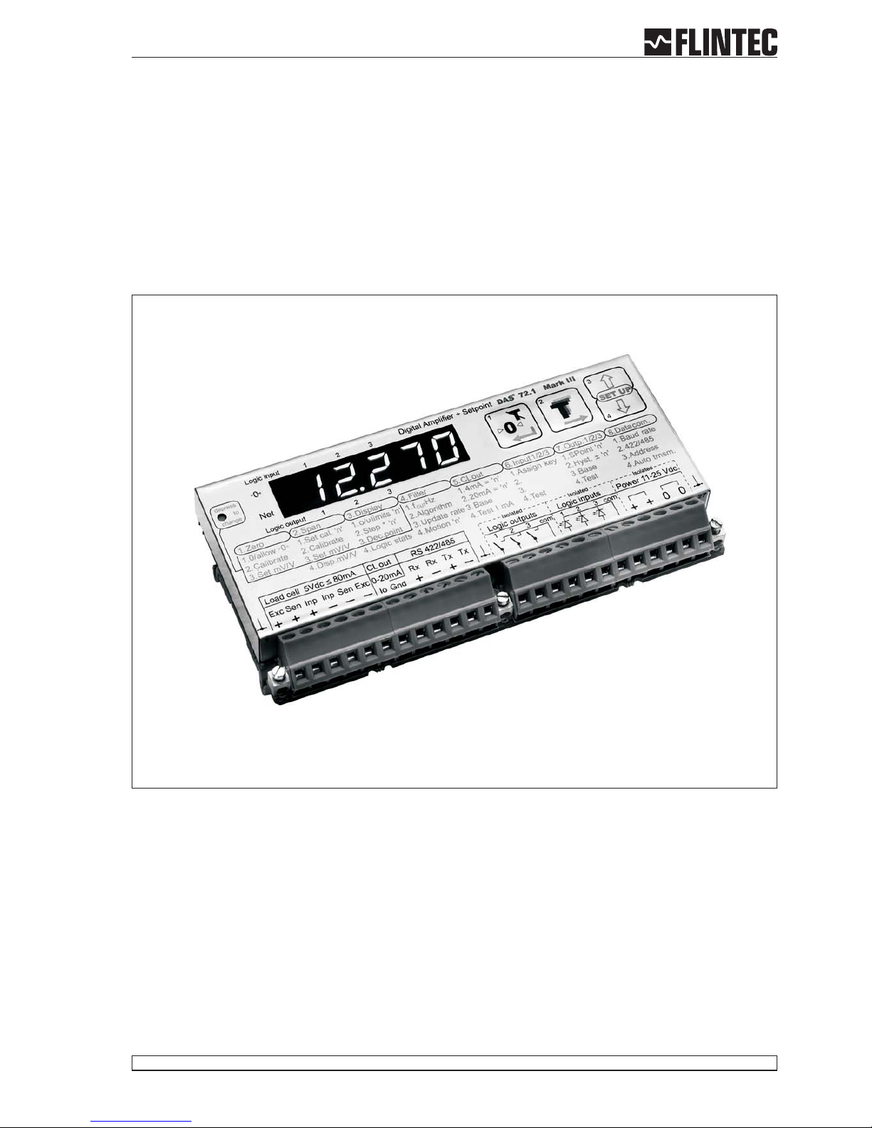
The model DAS 72.1 Mark III is a high precision, high speed digital amplifier for weighing and force
measurements with strain gauge (SG) sensors. The device can be controlled either by the front keys or via RS
485 port. 3 Logic inputsand outputs makecomplex control functionseasy.The 3 logic outputscan be controlled
external too.
With the available as standard analogue output 4…20 mA the DAS 72.1 fulfills industrial requirements. The
device features full multi-drop communications capability and can be programmed via a straightforward ASCII
command set. The LDU xx.x series and the amplifier DAS 72.1 with on-board digital display, use the same
command set. You can connect up to 32 SG amplifiers of either the LDU XX.X series or DAS 72.1 type onto a
single RS485 bus.
The DAS 72.1 with its high precision 18-bit A to D converter and internal sample rate of up to 2400 measure
-
ments / second, is particularly suitable for high dynamic measurements and control purposes.
Page 2 Manual DAS 72.1
Linearity < 0.002 %
Excitation 5 V DC, load cells 80-2000 Ohm, 6 wire technique
Analogue input range ±3.2 mV/V (bipolar, for weighing applications and force measurements)
Minimum input per vsi 0.05 μV/d
Resolution Internal ±260000 counts, ±18-Bit-A/D convertor; display max. ±99999 counts
Conversion rate Internal 2400 measurements per second; external up to 600 measurements per second
Digital filter FIR Filter 2.5 ... 19.7 Hz or IIR Filter 0.25 ... 18 Hz; programmable in 8 steps each
Calibration Software calibration and set up
Computer interface RS485 or RS422, full duplex, 9600 ... 115200 Baud; bus capability up to 32 devices
(RS485)
Weighing functions zero, gross, tare, net, filter etc.
Analogue output 0/4...20 mA, 14-Bit resolution
Display 10.2 mm LED, green, 5 digits, 3 status LED for nett/motion/sign,
6 status LED for logic inputs and outputs
Logic inputs 3 opto-isolated inputs, 10 ... 30 V DC, max. 3.5 mA
Logic outputs 3 opto-isolated outputs, < 45 V DC / AC, 1 A
Temperature effects on zero 5 ppm/°K typ.; max. <10 ppm/°K
on span 4 ppm/°K typ.; max. <8 ppm/°K
Temperature range –10 °C to +50 °C (operating); –20 °C to +60 °C (storage)
Enclosure tinned steel enclosure, protection IP 40; for 35 mm DIN-rail mounting.
Special housing IP 65 on request.
Dimensions 135 x 66 x 19 mm, weight ca. 180 g
Power supply 11 ... 25 V DC ±10 %, < 3 W, galvanically isolated
EMC CE 73/23/EEC; 93/98/EEC and 89/336/EEC
All dimensions in mm. Dimensions and specifications are subject to change without notice.
DAS 72.1 Mark II / III Specifications
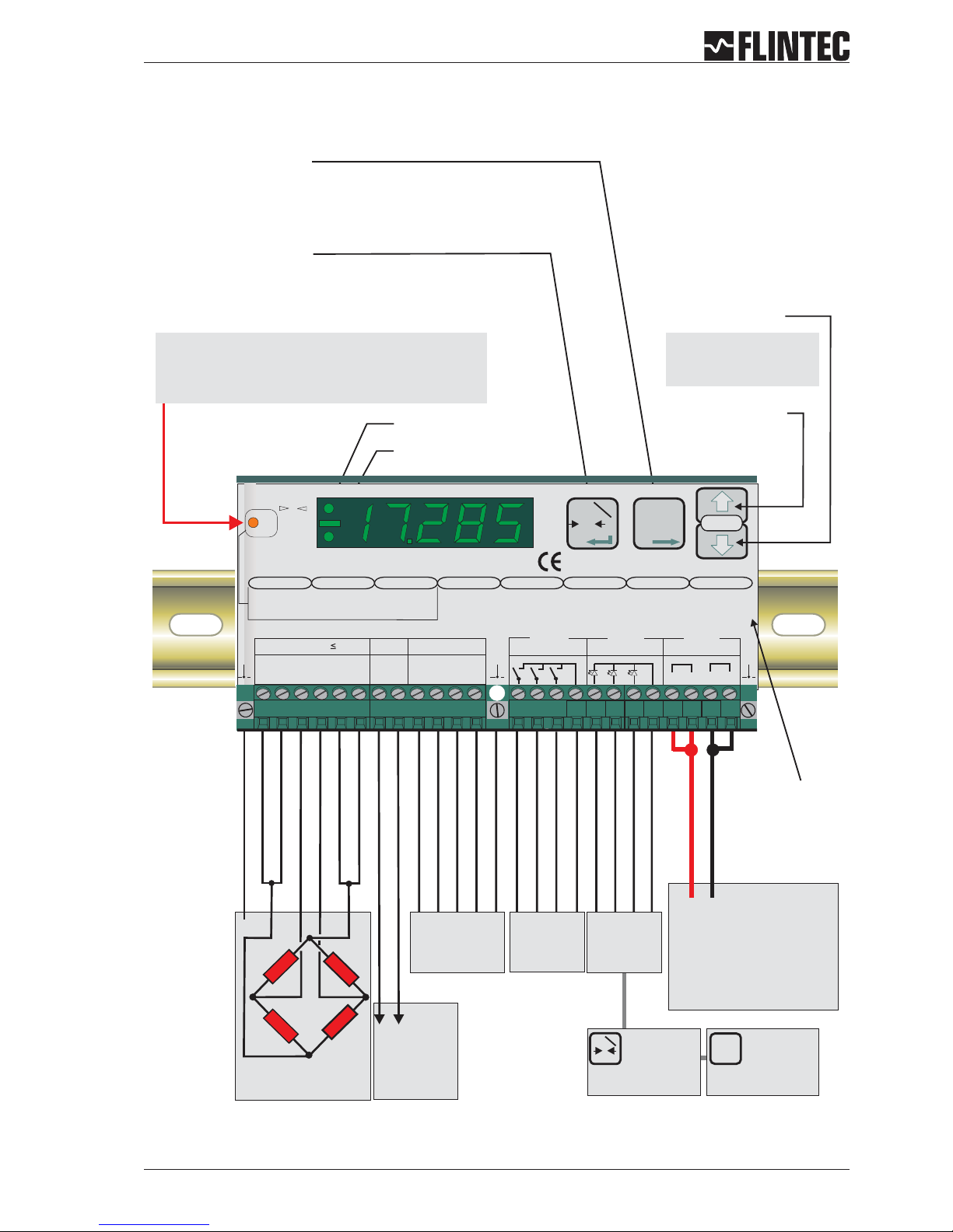
A.2 KEY FUNCTIONS
Manual DAS 72.1 Page 3
T
T
T
Inp.2
0
T
Inp.1
- SIGNAL
SHIELD
- EXCITATION
- SENSE
+ EXCITATION
+ SENSE
+SIGNAL
Load cell
connections
Power supply
12-25 V DC
+0
Input 1
(Functions as
Zero button,
Tare off, Set zero,
see paragraph B.3.6)
Net mode LED
Zero Key
Sets new zero (if enabled). Reverts to calibrated zero
if the button is held down for more than 3 seconds.
Switches unit back to ‘Gross’ mode if a tare has been
set. Acts as the‘Enter’ key in the ‘Set-up’ Mode.
Tare Key
Puts unit into ‘Net’ mode.When inside
‘Set-up’ Menu this key moves the menu
back one step. Also moves‘Digit Selected’
to the right inside sub menus.
“Set up”
menu structure
Press either key for
more than 3 seconds
to enter the set up mode
Recessed Enable Switch
(Enables changes to be made to important parameters.
Must be pressed before attempting to change
parameters 1.1 to 1.3, 2.1 to 2.3 and 3.1 to 3.3)
RS422/485
COM port
No motion LED
Logic
outputs
Logic
inputs
Input 2
(Functions as
Tare button,
Display net mode,
see paragraph B.3.6)
Down key
Up key
0 4-20mA
analogue
output
/
+0
Receive +
Receive -
Transmit +
Transmit -
Ground
Logic Input 1 (+)
Logic Input 2 (+)
Logic Input 3 (+)
Commmon
0
Net
Digital Amplifier + Setpoint DAS 72.1
+++ +
+
+
+
0-20mA
--- -
-
0
0
Exc Sen Sig Sig Sen Exc Rx Rx Tx Tx
Load cell 5Vdc 80mA
Isolated
Logic Outputs
Isolated
Logic Inputs
Isolated
Power 11 -25Vdc
RS422/485CL out
SET UP
1.Zero
1.0/allow>0<
2.Calibrate
3.Set mV/V
2.Span
1.Set cal. ´n´
2.Calibrate
3.Set mV/V
4.Disp.mV/V
3.Display
1.o/u limits´n´
2.Step * ´n´
3.Dec.point
4.Logic stats
4.Filter
1.f Hz
2.Algorithm
3.Update rate
4.
cut
Motion´n´
5.CLout
1.4mA=´n´
2.20mA=´n´
3.Base
4.TestImA
6.Input 1/2/3
1.Assign key
2.
3.
4.Test
7.Outp. 1/2/3
1.SPoint ´n´
2.Hyst. ´n´
3.Base
4.Test
±
8.Datacom.
1.Baud rate
2.422/485
3.Address
4.Auto trnsm.
T
T
T0
T
Inp.1 Inp.2
1
2 3 4 5 6 7 8 9 10 111213
14 27
261516 17 2324 251819 202122
12 3com
12 3com
Mark III
Io Gnd
Logic input 1 2 3
123
Logic output
Depress
To
Change

B KEYBOARD SET UP
Page 4 Manual DAS 72.1
A GENERAL 2
A.1 INTRODUCTION AND SPECIFICATION 2
A.2 KEYFUNCTIONS 3
B KEYBOARDSET UP 4
B.1 SHORTMANUALOF KEYBOARD SETUP 5
B.2 SETUPTABLE 6
B.3 SETUP FLOWCHARTS 7
B.3.1 Zerosetup,Menu 1.1 - 1.4 7
B.3.2 Spansetup,Menu 2.1 -2.4 8
B.3.3 Displaysetup,Menu 3.1 - 3.4 9
B.3.4 Filter / nomotion set up, Menu 4.1-4.4 10
B.3.5 Analogueoutput set up, Menu 5.1-5.4 11
B.3.6 Logicinput set up, Menu 6.1.3-6.3.4 12
B.3.7 Logicoutput set up, Menu 7.1-7.3 14
B.3.8 Datacommunication set up,menu 8.1 - 8.4 15
B.3.9 Errorcodes 16
B.4 EXAMPLES 17
B.4.1 Example1,calibration procedure using weights 17
B.4.2 Example2,calibration procedure using loadcell mV/V sensitivity and
zero offset 19
B.4.3 Example3,calibration procedure using loadcell mV/V sensitivity 21
D CEKONFORMITÄTSERKLÄRUNG 57
B.1 SHORT MANUAL OF KEYBOARD SETUP
Manual DAS 72.1 Page 5
Setup menu : To enter, press one of the arrow keys for 3 seconds. To change calibration data, also press recessed switch (to the left of the display) once.
1. ZERO 2. Span 3. Display 4. Filter 5. CL out 6. Input 1/2/3 7. Output 1/2/3 8. Data Com
1. 0 / allow >O< 1. Set cal.”n” 1. o/u limits ‘n’ 1. f-cut Hz 1. 4 mA=’n’ 1. Assign key 1. SPoint ‘n’ 1. Baud rate
2. Calibrate 2. Calibrate 2. Step*’n’ 2. Algorithm 2. 20 mA=’n’ 2. 2. Hyst +/- ‘n’ 2. 422/485
3. Set mV/V 3. Set mV/V 3. Dec.point 3. Update rates 3. Base 3. 3. Base 3. Address
4. Tare Memory 4. Disp. mV/V 4. Logic stats 4. Motion ‘n’ 4. Test I mA 4. Test 4. Test 4. Auto trnsm.
1. Zero Tracking or Set
Zero lock / unlock
2. Calibrate Zero with
actual or external
simulated input
signal
3. Calibrate Zero to
display "Zero” with
manual setup of
mV/V signal
4.1 Tare "ON":= Tare
value stred
non-volatile
Tare "OFF": Tare
value deleted at
power off
4.2 EX-Modus
"ON" Load cells
connected with
Zener barriers
"OFF" Load cells
connected without
Zener barriers
1. Calibration value for
actual measured
signal after 2.2 or
with internal mV/V
signal after 2.3
should be displayed
Example: 10 000 (g)
2. Input signal of load
cell(s) connected or
will be simulated by a
simulator
This signal refers to
calibrate value of
setup 2.1
3. Input signal in mV/
setupwiththefront
panel keys
This signal refers to
calibrate value of
setup 2.1
1,6500 mV/V @ 1000
(g)
4. Display of actual
input signal in mV/V
For test purposes
1. Measured value
at which the display
shows an overload (o)
or an underload (u)
2. Display step size as
1, 2, 5, 10, 20 etc
3. Position decimal
point of the display
Example:
000.00 @ 100.00(g)
4. Display I/O:
• No Status I/O
• Short display of
status
(approx 1,5 s)
• Permenant status
I/O
1. Cut off frequency
adjustable from
1=18Hzto
8 = 0.25 Hz
Typical setup:
"4"=3 Hz
2. Select Filter Type:
• FIR-Filter for quick
signal changes
• IIR-Filter for high
dampening
•
3. Update rate
This setup has
additional influence
on filters
4.1 No Motion Range
4.2 Stabilisation time
for in motion band
(Tare, Zero and
Zero Tracking are
only allowed at
"No Motion")
1. Setup value for an
output of 4 mA
Example:
0.0 (g) @ 4 mA
2. Setup value for an
output of 20 mA
Example:
1000 (g) @ 20 mA
3. Base of analogue
output:
• Gross value
• Nett value
• Average valuet
• Hold valuet
• Peak to Peak valuet
• Valley valuet
• Display value
• Swiched off
4. Simulate an analogue
output signal
Setup 12.345 for
getting an output
current of 12,345 mA
1. External Key control :
• (00) not used
• (01) Zero
• (02) Tare
• (03) Move up
• (04) Move down
• (05) External trigger
• (06) Get average
• (07) Display Peak
• (08) Delete Peak
• (09) Display Hold
• (10) Peak to Peak
• (11) Display Valley
• (12) Key lock
• (13) Store Weight
• (14) Tare and delete
2. not used
3. not used
4. Test of Logic inputs
The display shows
the signal status of
logic inputs
Standard display is
switched off!
1.1
Setup setpoints
for outputs 1/2/3
1.2 Setup switch logic
for:
• on
• off
•
2. Setup Hysteresis of
setpoints
3. Base of Outputs:
• (0) Gross
• (1) Net
• (2) Peak
• (3) Average
• (4) Hold
• (5) Peak to Peak
• (6) Valley
• (7) Error 4 or 5
• (8) Swiched of
4. Test of Logic outputs
The display shows
the signal status of
logic outputs
Standard display is
switched off!
1. Setup Baudrate:
9600...115,2 k Baud
2. Setup Mode for Com.
ports
• RS-422 full duplex
• RS-485 Network
•
3. Setup Port Address
Valid addresses
0...255
Address "0" device is
always active on bus
Address enable via
"open"
4. Auto Transmit of
data:
• Gross
• Net
• All (Data string)
• Sap (A/D value)
• Aver (Average
value)
• Pea (Peak value
• Hold (Hold value)
• Vall (Valley value)
• Pp (Peak to Peak
value)
• Off (switched off)

B.2 SETUP TABLE
Page 6 Manual DAS 72.1
Description
LED Display Pre Setup Example: 3000 kg scale
with 0.5 kg step
Menu Point Value Value Result
Function Zero key (on/off))
Zero Calibration / Weight
Zero Calibration / mV/V
<1.1>
<1.2>
<1.3>
0-oFF
0.000
0.000
0-oFF
0.000
0.400
Set zero not
possible
kg
mV/V
Span / Weight or mV/V
Span / Weight
Span / mV/V
Displays Actual mV/V Signal
<2.1>
<2.2>
<2.3>
<2.4>
20000
0.000
2.000
--
a)3000.0 or
b)750.0
0.9
2.000
--
Cal. with mV/V
Cal. with 750 kg
mV/V
mV/V
-Maximum Display Value
Maximum Display Value
Display Step Size
Decimal Point Position
Display Status I/O
< 3.1.o >
< 3.1.u >
<3.2>
<3.3>
<3.4>
99999
-9999
1
0
1
3100.0
-200.0
5
0.0
1
kg
kg
0,5 kg
0000.0
Status for 1 s
Cut Off Filter Frequency
Filter Type
Update Rate per second (filtered)
No Motion Range
<4.1>
<4.2>
<4.3>
<4.4>
33.3
FIR
3
1
3.0
FIR
3
1
Hz
for quick signal
changes
measurements/s
Set Analogue Output @ 4 mA
Set Analogue Output @ 20 mA
Base of Analogue Output
Simulate Analogue Output Signal
<5.1>
<5.2>
<5.3>
<5.4>
00000
20000
gross
--
0.0
3000.0
gross
--
kg
kg
gross
-Input 1 for External Key Control
Input 2 for External Key Control
Input 3 for External Key Control
Read Iinput Status
Base of Digital Inputs
Test Logic Inputs
< 6.1.1 >
< 6.2.1 >
< 6.3.1 >
<6.2>
<6.3>
<6.4>
--
--
--
--
--
--
--
--
--
--
--
--
--
--
--
--
--
-Output Setpoint 1
Output Setpoint 2
Output Setpoint 3
Hysteresis & Logic Setpoint 1
Hysteresis & Logic Setpoint 2
Hysteresis & Logic Setpoint 2
Base Setpoint 1
Base Setpoint 2
Base Setpoint 3
Function Test Output 1
Function Test Output 2
Function Test Output 3
< 7.1.1 >
< 7.2.1 >
< 7.3.1 >
< 7.1.2 >
< 7.2.2 >
< 7.3.2 >
< 7.1.3 >
< 7.2.3 >
< 7.3.3 >
< 7.1.4 >
< 7.2.4 >
< 7.3.4 >
99999
00000
oFF
--
--
--
--
--
--
--
--
--
0000.0
1000.0
3000.0
0000.0
0000.0
0000.0
net
net
net
--
--
--
kg
kg
kg
kg
kg
kg
net
net
net
--
--
-Baudrate RS-422/485 Port
Port Mode (422 or 485)
Device Address Com Port
Auto Transmit Data
<8.1>
<8.2>
<8.3>
<8.4>
9600
422
0
oFF
9600
422
0
nEt
Baud
422-Port
Device No.
auto transmit
net weight

B.3 SET UP FLOWCHARTS
B.3.1 Zero set up, Menu 1.1 - 1.4
Manual DAS 72.1 Page 7
Store Tare value, setting ON or OFF
OFF: Tare value deleted at power off
ON: Tare value stored non-volatile (max. 1 000 000 times)
0
T
Inp.1
0
T
Inp.1
CALIBRATE OR ADJUST THE ZERO POINT
Remark:
(CONVENTIONAL WEIGHING SYSTEM)
Display shows the actual input signal in mV/V.
Press the Enter key to store the zero.
scale should be unloaded.
CALIBRATE THE ZERO POINT FROM THE LOAD CELL mV/V READING
Use the UP/DOWN & MOVE RIGHT keys to set the mV/V reading at which the
unit should read zero.
SET UP
0
T
Inp.1
T
T
T
T
T
T
Inp.2
Inp.2
0
T
Inp.1
0
0
T
T
Inp.1
Inp.1
Press the UP or DOWN key
for more than 3 seconds to enter the Set-up Menu
0
T
Inp.1
T
T
T
Inp.2
Note:
Recessed Enable Switch
(Enables changes to be made
to important parameters.
Must be pressed before
attempting to change parameters
1.1 to 1.3, 2.1 to 2.3 and 3.1 to 3.3)
Automatic Zero Tracking
Settings: 0 ... 255 d
Function is swiched off at setting 00 000.
Zero Setting with zero key or by external signal is not possible (Menu 6).
Function is swiched on at setting 00 001 or higher, (max 00 255).
Zero Setting with zero key or by external signal (Menu 6).
Setting 00 001 sets a zero range of +/-2%ofUpper Display Limit (Menu 3.1),
setting 00 002 up to 00 255 sets a range of2dupto255d(independant of
decimal point setting).
0
T
Inp.1
T
T
T
T
T
T
Inp.2
Inp.2
0
T
Inp.1
T
T
T
Inp.2
0
T
Inp.1
EX-Modus, setting ON or OFF
OFF:Load cell connection without Zener barrieres
ON: Load cell connection with Zener barrieres,
extended error band for ERR 5
0
T
Inp.1
0
T
Inp.1
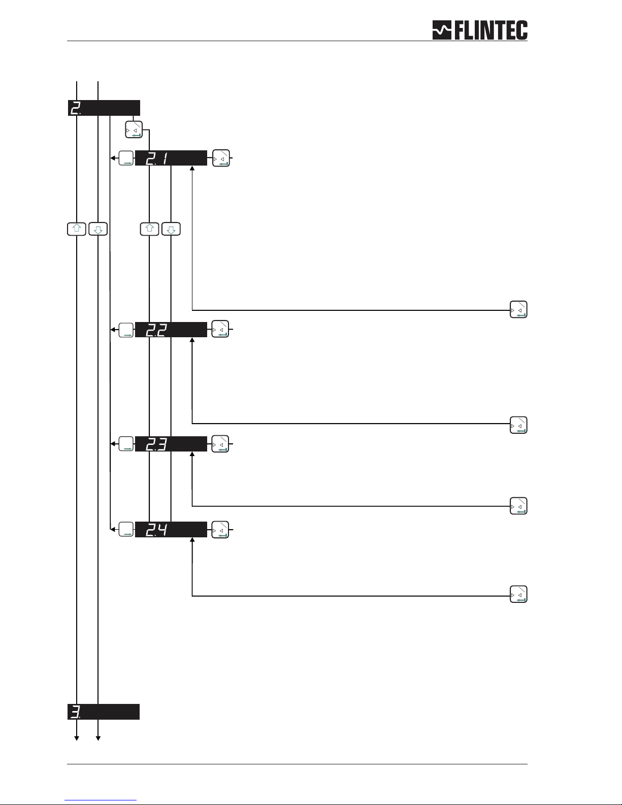
B.3.2 Span set up, Menu 2.1 - 2.4
Page 8 Manual DAS 72.1
0
T
Inp.1
0
T
Inp.1
0
T
Inp.1
0
T
Inp.1
T
T
T
T
T
T
T
T
T
T
T
T
Inp.2
Inp.2
Inp.2
Inp.2
0
0
0
T
T
T
Inp.1
Inp.1
Inp.1
0
T
Inp.1
0
T
Inp.1
SET THE SPAN CALIBRATION VALUE
Twopossibilities areavailable:
A. Setthedisplayvalueequivalent tothecalibrationweight,continue withstep2.2
or
B. Use themV/Vsignalderivedfromthe loadcell(s)test data,continuewith step2.3.
CALIBRATE THE SPAN (CONVENTIONAL WEIGHING SYSTEM)
Display shows the actual input signal in mV/V.
Apply test weights equivalent to the calibration value set in section 2.1. Press the Enter
key to store the new span value.
CALIBRATE THE SPAN FROM THE LOAD CELL mV/V READING
Use the UP/DOWN & MOVE RIGHT keys to set the mV/V reading at which the unit should
read the value set in section 2.1.
DISPLAY THE INPUT SIGNAL IN mV/V
This function allows you to view the input signal in mV/V.
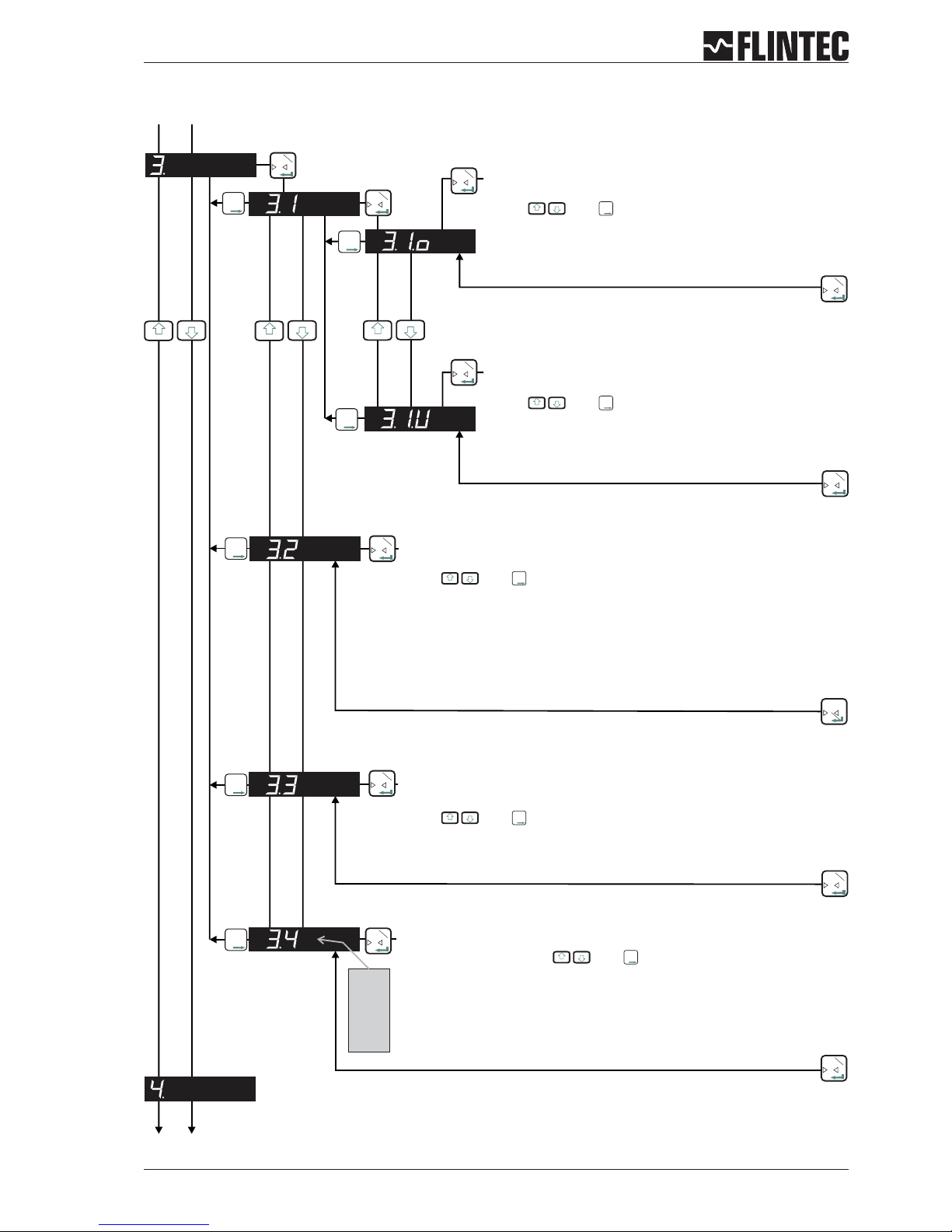
B.3.3 Display set up, Menu 3.1 - 3.4
Manual DAS 72.1 Page 9
0
T
Inp.1
0
T
Inp.1
0
T
Inp.1
0
T
Inp.1
0
T
Inp.1
0
T
Inp.1
T
T
T
T
T
T
T
T
T
Inp.2
Inp.2
Inp.2
0
T
Inp.1
0
T
Inp.1
0
T
Inp.1
0
T
Inp.1
SET THE DISPLAY OVER RANGE LIMIT
(MAXIMUM VALUE +99 999)
Use the and keys to set the maximum display value
above which the display shows over range (all dashes in the top of the
display).
SET THE DISPLAY UNDER RANGE LIMIT
(MINIMUM VALUE -99 999)
Use the and keys to set the minimum display value
below which the display shows under range (all dashes in the bottom
of the display).
SET THE DISPLAY DIVISION OR STEP SIZE
(1, 2, 5, 10, 20, 50, 100, 200, 500)
Use the and keys to set the required display division or step size.
SET THE DECIMAL POINT POSITION ON THE DISPLAY
(0, 0.0, 0.00, 0.000, 0.0000)
Use the and keys to set the required decimal point position on the
display.
LOGIC I-O STATUS
Select setting 0, 1 or 2 with and .
Setting 0 = Continious indication of Weight, no input/output status.
Setting 1 = Indication of Weight, short indication input/output status (ca. 1,5 sec)
Setting 2 = Continious indication of input/output status.
0
T
Inp.1
T
T
T
T
T
T
T
T
T
Inp.2
Inp.2
Inp.2
0
T
Inp.1
3.4.0
3.4.1
3.4.2
T
T
T
Inp.2
T
T
T
Inp.2
T
T
T
Inp.2
T
T
T
Inp.2
T
T
T
Inp.2

B.3.4 Filter / no motion set up, Menu 4.1 - 4.4
Page 10 Manual DAS 72.1
0
T
Inp.1
0
T
Inp.1
T
T
T
Inp.2
0
T
Inp.1
Set the low pass filter cut off frequency
: Setting
Set Range: 0 - 8 with
Filter setting 18 Hz (4.1.1) to 0.25 Hz (4.1.8) with Filter type IIR.
Filter setting 19.7 Hz (4.1.1) to 2.5 Hz (4.1.8) with Filter type FIR.
“0” (4.1.0) deactivates the Filter.
See Paragraph C.4.5 for more information.
Attention
Set the type of low pass filter required
Setting with
: FIR or IIR
Type IIR should be used where heavy damping is required.
Type FIR should be used where high speed is required.
Defines the number of filtered readings averaged
Attention:
Set Range: 0-7mit
This Parameter defines the number of Readings from the IIR or FIR filter that
will be averaged.
Selection between “0” (1 Reading) and “7” (128 Readings).
See Paragraph C.4.5 for more information.
Set the No Motion Range
Attention:
Set Range: 0 - 30 000 steps and
Fluctuations in weight values inside this range will be considered as
‘stable’.
See also 4.4.2 for the Stabilisation Time
If the condition of the No Motion Range is fullfilled within the Stabilistion
Time the “No Motion” status bit will be set to allow zero setting, taring as
well as calibrating zero and span.
0
T
Inp.1
0
T
Inp.1
0
T
Inp.1
0
T
Inp.1
0
T
Inp.1
0
T
Inp.1
T
T
T
T
T
T
Inp.2
Inp.2
0
T
Inp.1
T
T
T
Inp.2
0
T
Inp.1
Set the Stabilisation Time
Set Range: 0 - 30 000 mS with and
Sets the Stabilisation Time in milliseconds within which the weight value
displayed has to remain within the No Motion Range, for the weigh to be
considered ‘stable’.
0
T
Inp.1
T
T
T
Inp.2
4.1.0
:
:
:
4.1.8
4.3.0
:
:
:
4.3.7
T
T
T
Inp.2
T
T
T
Inp.2
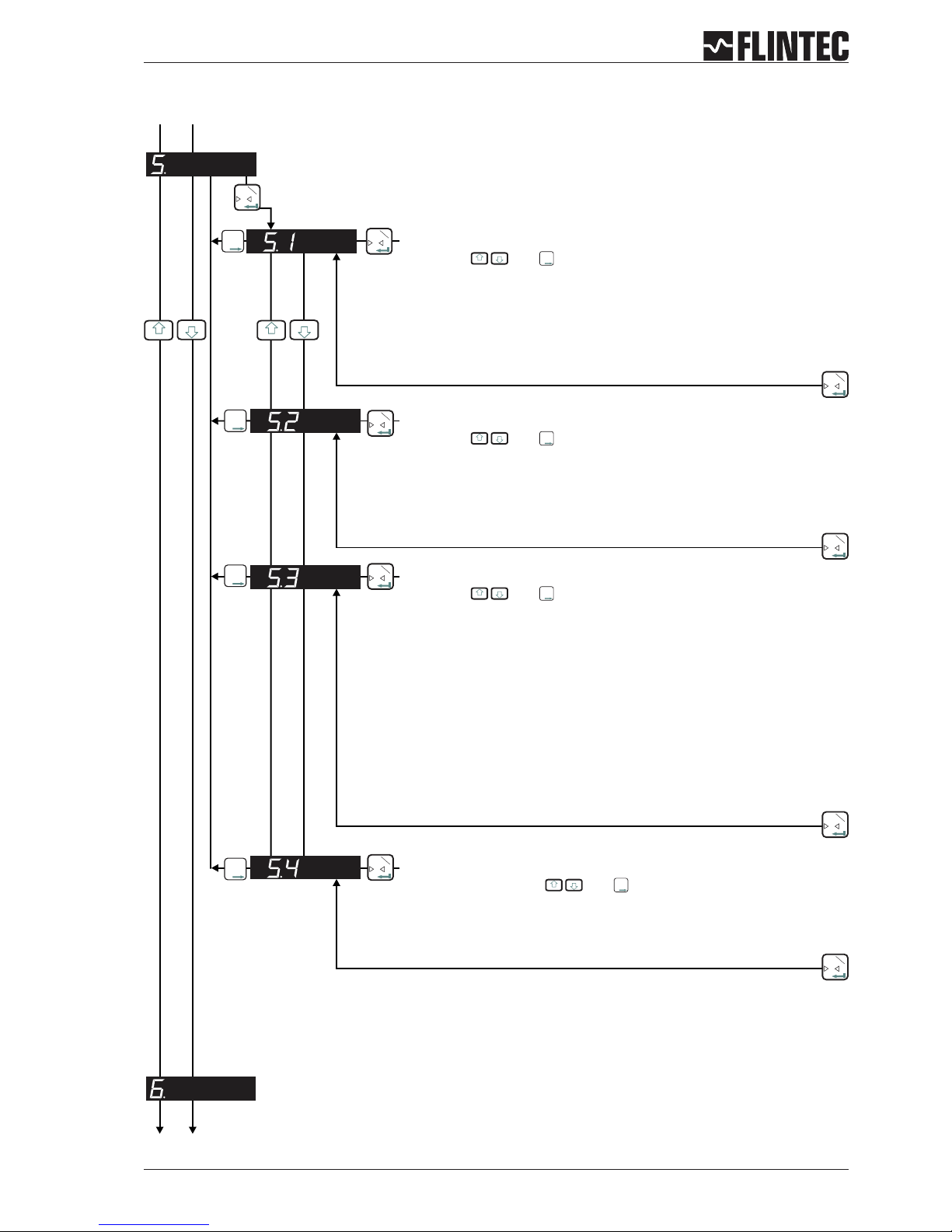
B.3.5 Analogue output set up, Menu 5.1 - 5.4
Manual DAS 72.1 Page 11
0
T
Inp.1
T
T
T
Inp.2
0
T
Inp.1
0
T
Inp.1
0
T
Inp.1
T
T
T
T
T
T
Inp.2
Inp.2
0
T
Inp.1
T
T
T
Inp.2
0
T
Inp.1
0
T
Inp.1
0
T
Inp.1
0
T
Inp.1
Set the weight value at which 4 mA is send
Examples:
Setting with and
Set the weight value at which 4 mA is send.
Weighing range 3 000 kg and 3 000 d with 0/4...20 mA.
Analogue output 4...20 mA: for 0 kg=4mAmake setting 00 000.
Analogue output 0...20 mA: for 600 kg=4mAmake setting 00 600.
Set the weight value at which 20 mA is send
Examples:
Setting with and
Set the weight value at which 20 mA is send.
Weighing range 3 000 kg and 3 000 d with 0/4...20 mA.
Analogue output 4...20 mA: for 3 000 kg = 20 mA make seting 03 000.
Analogue output 0...20 mA: for 3 000 kg = 20 mA make seting 03 000.
Set the analogue output base
GROS Gross
NET Net
PEA Peak
AVER Average
HOLD Hold
PP Peak÷Peak
VALL Valley
DISP Display
OFF OFF
Setting with and for the following values:
= Analogue output follows value
= Analogue output follows value
= Analogue output follows value (maximum)
= Analogue output follows value
= Analogue output follows value
= Analogue output follows value
= Analogue output follows value (minimum)
= Analogue output follows value
= Analogue output is switched
Test the current output
Set Range 0...20 mA with . And
Set a current value in mA, which will be sent down the analogue output,
independent of the load applied to the weighing system.
T
T
T
Inp.2
T
T
T
Inp.2
T
T
T
Inp.2
T
T
T
Inp.2
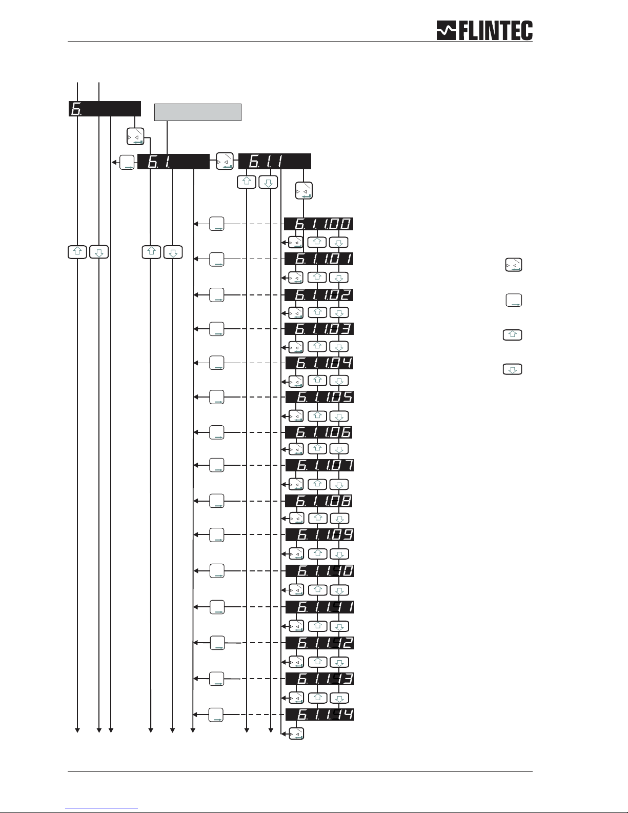
B.3.6 Logic input set up, Menu 6.1.3 - 6.3.4
Page 12 Manual DAS 72.1
T
T
T
2
T
T
T
2
T
T
T
2
T
T
T
2
T
T
T
2
T
T
T
2
T
T
T
2
T
T
T
2
T
T
T
2
T
T
T
2
T
T
T
2
T
T
T
2
T
T
T
2
T
T
T
2
0
T
1
0
T
1
0
T
1
0
T
1
0
T
1
0
T
1
0
T
1
0
T
1
0
T
1
0
T
1
0
T
1
0
T
1
0
T
1
0
T
1
0
T
1
0
T
1
0
T
1
T
T
T
2
T
T
T
2
0
T
1
0
T
1
Set the function for Logic Input “1”
Possible settings: 00, 01 ,02 ,03 ,04 ,05 ,06 ,07, 08, 09,
10, 11, 12, 13, 14.
Input “1” no function
Input “1” acts as Zero button
Input “1” acts as Tare button
Input “1” acts as Up arrow button
Input “1” acts as Down arrow button
Input “1” starts the Trigger function
Input “1” displays the Average value
Input “1” displays the Peak value (maximum)
Input “1” displays the Hold value
Input “1” displays the Peak to Peak value
Input “1” displays the Valley value (minimum)
Input “1” stores the actual weight (Hold value)
Input “1” disables the keyboard
Input “1” tares the display and deletes all other
values like 6.1.1.08
Input “1” deletes the Peak value
T
T
T
2
The second digit coresponds
with the input number
Fortsetzung nächste Seite
12
3
4
56
7
8
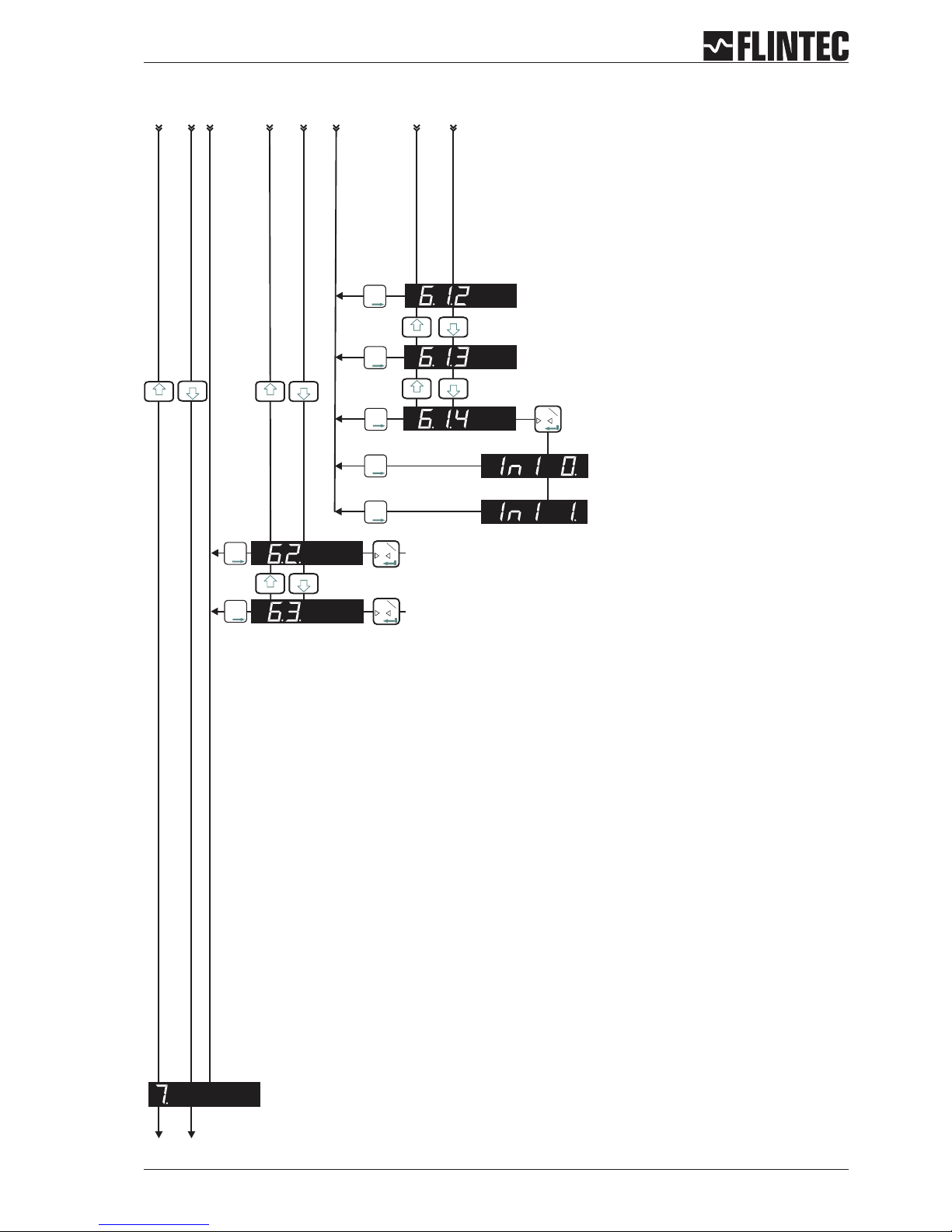
Logic input set up, Menu 6.1.3 - 6.3.4 (continued)
Manual DAS 72.1 Page 13
0
T
1
T
T
T
2
0
T
1
0
T
1
T
T
T
T
T
T
T
T
T
T
T
T
T
T
T
T
T
T
2
2
2
2
2
2
Check Logic Input “1”
(6.1.1. must be set to “0” => 6.1.1.0)
“In1 1.” Input is ”high”
As per section 6.1 but for Logic Input “2”
As per section 6.1 but for Logic Input “3”
“In1 0.” Input is ”low”
No function
No function
12
3
4
56
7
8
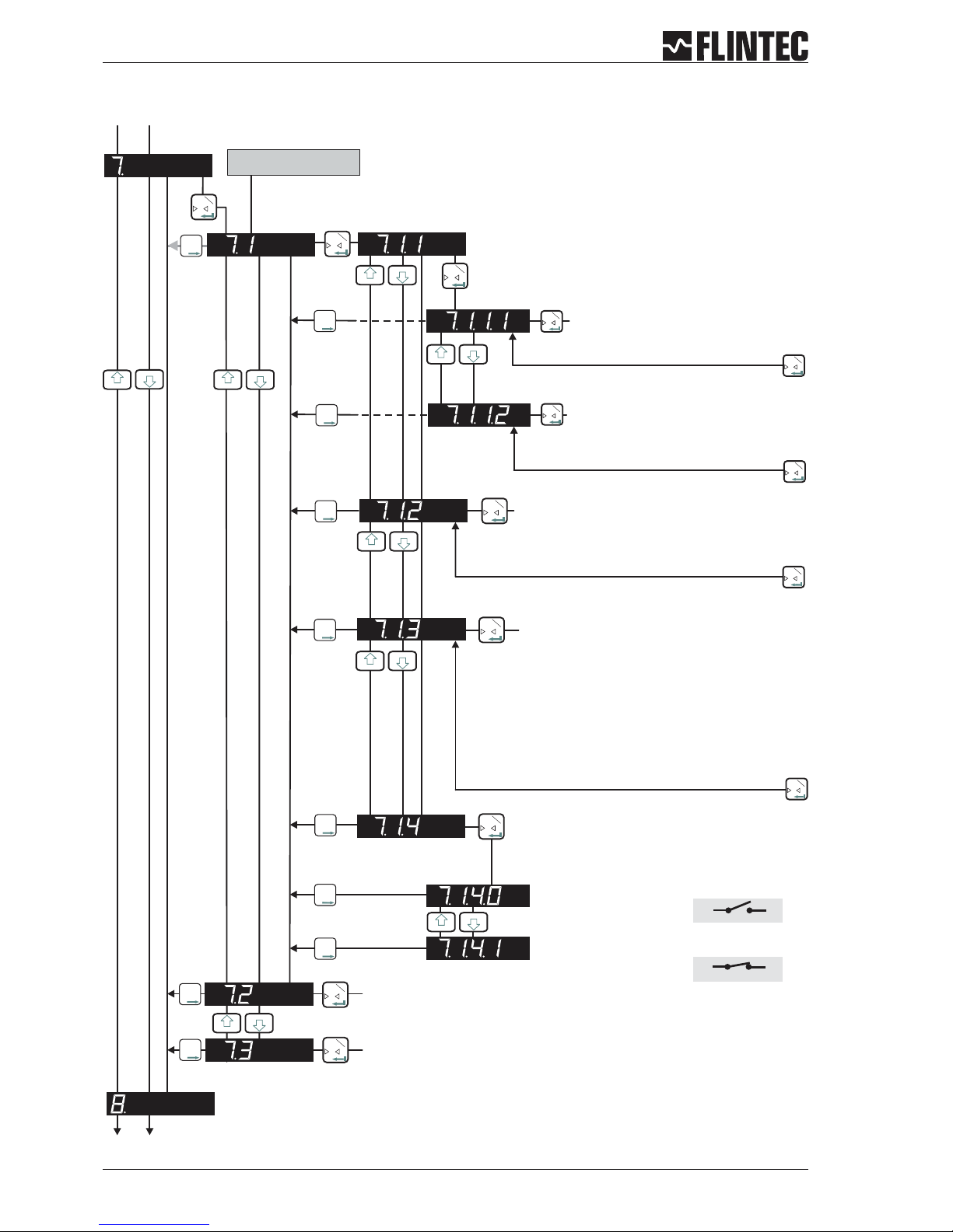
B.3.7 Logic output set up, Menu 7.1 - 7.3
Page 14 Manual DAS 72.1
0
T
1
0
T
1
0
T
1
0
T
1
0
T
1
0
T
1
0
T
1
0
T
1
T
T
T
2
0
T
1
0
T
1
T
T
T
2
0
T
1
Set the function for Logic Output “1”
Set whether Logic Output “1”
switches ON or OFF
Use the UP/DOWN keys to set whether
logic output 1 switches ON or OFF at the
Set the hysteresis value on the setpoint for
Logic Output “1”
Permitted values +/- 99 999.
Set base for Logic Output “1”
GROS Gross
NET Net
PEA Peak
AVER Average
HOLD Hold
PP Peak to Peak
VALL Valley
ERR Error
OFF OFF
= value
= value
= value (maximum)
= value
= value
= value
= value (minimum)
= 4 or 5
= Sets output
Set weight value at which Logic
Output “1” switches
Permitted values +/- 99 999
0
T
1
T
T
T
T
T
T
T
T
T
T
T
T
T
T
T
T
T
T
T
T
T
T
T
T
2
2
2
2
2
2
2
2
Check Logic Output “1”
Use the UP/DOWN keys to switch.
The output is “on”.
As per section 7.1 but for Logic Output “3”
The output is “off”.
0
T
1
0
T
1
out 1
out 1
com
com
The second digit coresponds
with the output number
As per section 7.1 but for Logic Output “2”

B.3.8 Data communication set up, menu 8.1 - 8.4
Manual DAS 72.1 Page 15
0
T
Inp.1
T
T
T
Inp.2
0
T
Inp.1
0
T
Inp.1
T
T
T
Inp.2
0
T
Inp.1
T
T
T
Inp.2
0
T
Inp.1
0
T
Inp.1
0
T
Inp.1
Set the Baud Rate for COMPORT (RS-422/485)
Setting with and
9 600 Baud
19 200 Baud
38 400 Baud
57 600 Baud
115 200 Baud
Select either RS-422 or RS-485
Setting with and
422 = RS-422-Interface (use for single DAS application)
485 = RS-485-Interface (use for multiple DAS application in BUS)
Set the Device Address Comport (RS-422/485)
Setting with and
Set the device address for multi-drop to 001 ... 255.
Set to 000 for single point to point applications.
T
T
T
Inp.2
T
T
T
Inp.2
T
T
T
Inp.2
0
T
Inp.1
T
T
T
Inp.2
0
T
Inp.1
Select the Autotransmit Mode
Setting with
= Gross value
= Net value
= Data string with Gross, Net and Status
= A/D value
= Average value
= Peak value (maximum)
= Hold value
= Valley value (minimum)
= Peak to Peak value
= Autotransmit OFF
GROS
NET
ALL
SAP
AVER
PEA
HOLD
VALL
PP
OFF
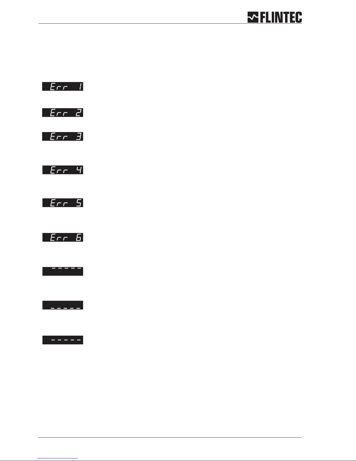
B.3.9 Error codes
Page 16 Manual DAS 72.1
Set final zero out of range.
(You are trying to set a zero which is greater than ±2% of the Upper Display Limit)
Excessive sensitivity requested.
(The input signal is being divided into too many divisions i.e the size of each division is < 0.5 V)m
Faulty load cell connection (Open circuit / Short Circuit / Wire disconnected)
You are trying to enter a value which is not valid (Outside the acceptable parameter range)
The input signal is in excess of ± 2.6 mV/V
Display underload (Display value is more negative than the lower limit set in Menu 3.1.U)
Display overload (Display value exceeds the upper limit set in Menu 3.1.o)
The zero key is not enabled (See menu 1.1)
Remark
If you need to return the DAS72.1 Mark III to the factory settings simply press and hold the recessed enable switch whilst
powering up the unit. All parameters will then revert to the factory settings
The Zero or Tare motion limit has been exceeded. Set Zero or Tare function disallowed.
Review Zero and Tare motion limits set in menu 4.4
B.4 EXAMPLES
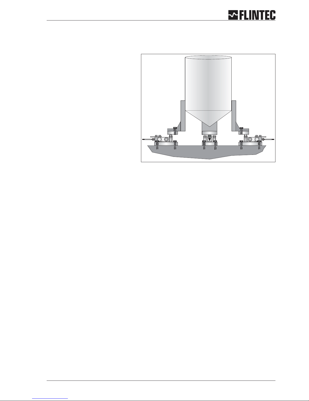
B.4.1 Example 1, calibration procedure using weights
Manual DAS 72.1 Page 17
3 Leg tank or silo fitted with 3 off 1000 kg
@ 2 mV/V load cells.
Dead load 600 kg.
Live range 2000 kg in 0.5 kg steps.
It is assumed that the load cell system is
connected to the DAS72.1 and the power
is on. The maximum and minimum display
values, display increment size and decimal
point position should be defined prior to
carrying out the calibration (See Menu 3).
For this example the display maximum is
defined as 2100.0, the display minimum is
-200.0, the display step size is 0.5 kg.
Remember that all parameters under
sections 1.1 - 1.3, 2.1 - 2.3 and 3.1 - 3.3 can only be accessed or changed after the Recessed Enable
Switch has been pressed.
a
Go to Menu 1.2 and using the UP/DOWN and RIGHT keys set the display to read 0000.0. Make sure that the
weighing system is empty or at the point where you want the display to read zero. Press the 0 [Enter] key.
This defines the actual zero calibration point.
b
Go to Menu 2.1 and using the UP/DOWN and RIGHT keys set the display to read the value of the calibration
weight(s) applied. For this example if the calibration load applied is 750 kg set the display to read 750.0.
Press the 0 [Enter] key. This defines the calibration weight.
c
Go to Menu 2.2.Apply the calibration weight(s) to the weighing system. Press the 0 [Enter] key. The display
will show the actual input signal in mV/V. Press the 0 [Enter] key. This defines the actual span calibration
point.The displaywill show 2.2. Press the rightarrow keytwice and theDAS will beback inweighing mode.
Calibration is now completed.
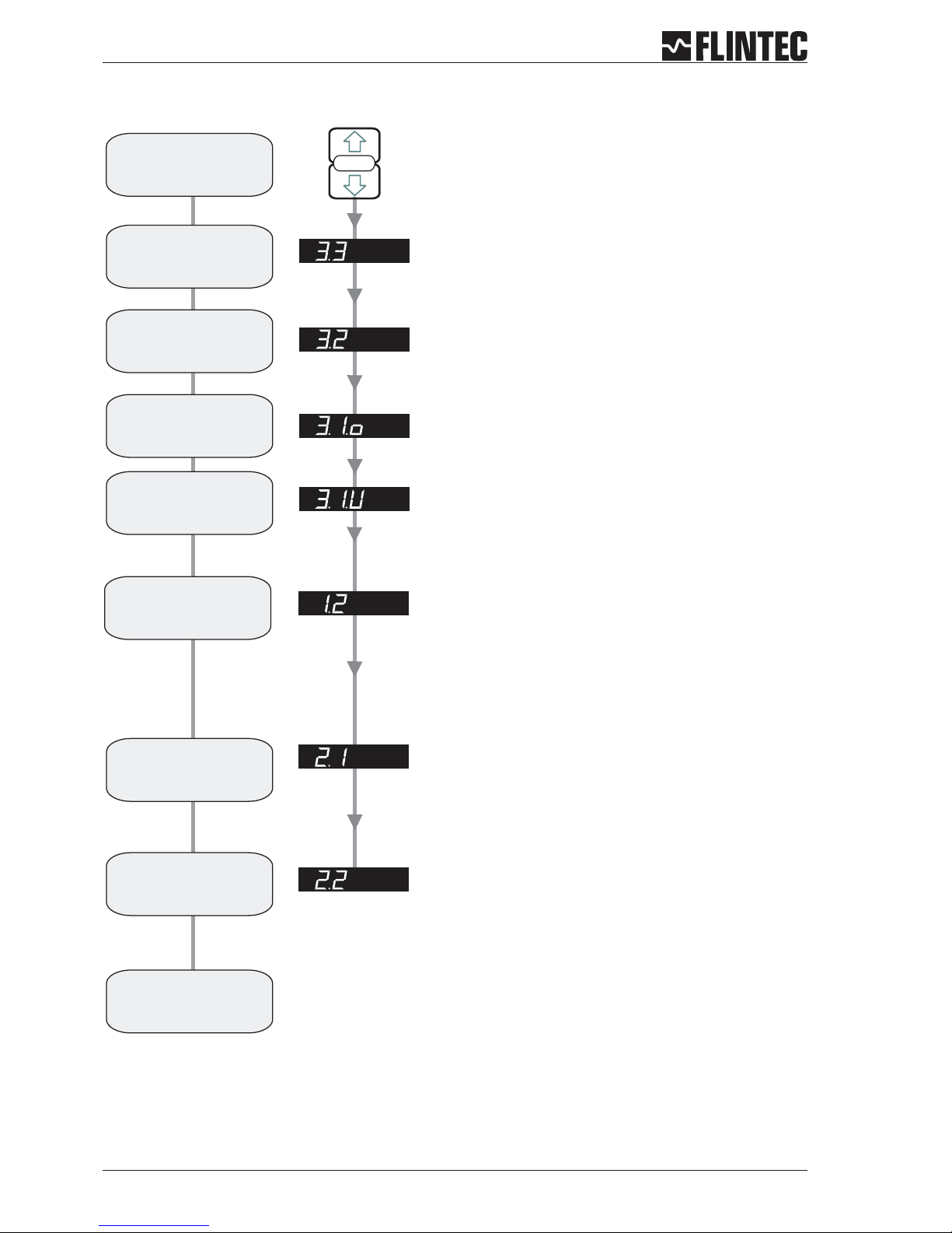
Flowchart Example 1
Page 18 Manual DAS 72.1
SET UP
SET THE DISPLAY STEP SIZE. (1, 2, 5, 10, 20, 50, 100, 200, 500)
Use the UP or DOWN key to set the required display step size.
1. Press the UP or DOWN key for more than
3 seconds to enter the Set-up Menu
2. Press the recessed enable switch
SET THE DISPLAY OVER RANGE LIMIT. (MAX. VALUE +99999)
Use the UP/DOWN & MOVE RIGHT keys to set the maximum display value
above which the display shows over range
(all dashes in the top of the display).
SET THE DISPLAY UNDER RANGE LIMIT. (MIN. VALUE -99999)
Use the UP/DOWN & MOVE RIGHT keys to set the minimum display value
below which the display shows under range
(all dashes in the bottom of the display).
SET THE DECIMAL POINT POSITION (0, 0.0, 0.00, 0.000, 0.0000)
Use the UP or DOWN key to set the required decimal point position.
Choose 0.0
SET THE SPAN CALIBRATION VALUE.
Use the UP/DOWN & MOVE RIGHT keys to set the display value equivalent
to the calibration weight, e.g. 750 kg.
CALIBRATE THE SPAN. (CONVENTIONAL WEIGHING SYSTEM)
Display shows the actual input signal in mV/V. Apply test weights equivalent
to the calibration value set in section 2.1.
Press the Enter key to store the new Span value
Choose Filter type IIR (menu 4.2), Low Pass Filter 6 ... 8 (menu 4.1)
and wait for ‘No Motion’ in the calibration routine.
Note:
Enter the
Set-up menu
Set the
step size
display
Set the Display
Upper Limit
(Overload)
Set the decimal
point position
Set the Display value
equal to the
Calibration weight
Calibrate
the Span
Calibration
completed
Set the Display
Lower Limit
Calibrate the
Zero point
CALIBRATE THE ZERO POINT. (CONVENTIONAL WEIGHING SYSTEM)
Display shows the actual input signal in mV/V.
 Loading...