


Process Indicator Type DAS 72.1 Mark III
MANUAL
Firmware Version 72.181.v.4.28 or higher
Hardware Version 72.101.5.v.3.0x
Document No G128 Rev6 GB
www.flintec.com
Manual DAS 72.1 Page 1

A GENERAL
A.1 INTRODUCTION AND SPECIFICATION
The model DAS 72.1 Mark III is a high precision, high speed digital amplifier for weighing and force
measurements with strain gauge (SG) sensors. The device can be controlled either by the front keys or via RS
485 port. 3 Logic inputsand outputs makecomplex control functionseasy.The 3 logic outputs canbe controlled
external too.
With the available as standard analogue output 4…20 mA the DAS 72.1 fulfills industrial requirements. The
device features full multi-drop communications capability and can be programmed via a straightforward ASCII
command set. The LDU xx.x series and the amplifier DAS 72.1 with on-board digital display, use the same
command set. You can connect up to 32 SG amplifiers of either the LDU XX.X series or DAS 72.1 type onto a
single RS485 bus.
The DAS 72.1 with its high precision 18-bit A to D converter and internal sample rate of up to 2400 measure
ments / second, is particularly suitable for high dynamic measurements and control purposes.
DAS 72.1 Mark II / III Specifications
Linearity < 0.002 %
Excitation 5 V DC, load cells 80-2000 Ohm, 6 wire technique
Analogue input range ±3.2 mV/V (bipolar, for weighing applications and force measurements)
Minimum input per vsi 0.05 μV/d
Resolution Internal ±260000 counts, ±18-Bit-A/D convertor; display max. ±99999 counts
Conversion rate Internal 2400 measurements per second; external up to 600 measurements per second
Digital filter FIR Filter 2.5 ... 19.7 Hz or IIR Filter 0.25 ... 18 Hz; programmable in 8 steps each
Calibration Software calibration and set up
Computer interface RS485 or RS422, full duplex, 9600 ... 115200 Baud; bus capability up to 32 devices
(RS485)
Weighing functions zero, gross, tare, net, filter etc.
Analogue output 0/4...20 mA, 14-Bit resolution
Display 10.2 mm LED, green, 5 digits, 3 status LED for nett/motion/sign,
6 status LED for logic inputs and outputs
Logic inputs 3 opto-isolated inputs, 10 ... 30 V DC, max. 3.5 mA
Logic outputs 3 opto-isolated outputs, < 45 V DC / AC, 1 A
Temperature effects on zero 5 ppm/°K typ.; max. <10 ppm/°K
on span 4 ppm/°K typ.; max. <8 ppm/°K
Temperature range –10 °C to +50 °C (operating); –20 °C to +60 °C (storage)
Enclosure tinned steel enclosure, protection IP 40; for 35 mm DIN-rail mounting.
Special housing IP 65 on request.
Dimensions 135 x 66 x 19 mm, weight ca. 180 g
Power supply 11 ... 25 V DC ±10 %, < 3 W, galvanically isolated
EMC CE 73/23/EEC; 93/98/EEC and 89/336/EEC
All dimensions in mm. Dimensions and specifications are subject to change without notice.
-
Page 2 Manual DAS 72.1
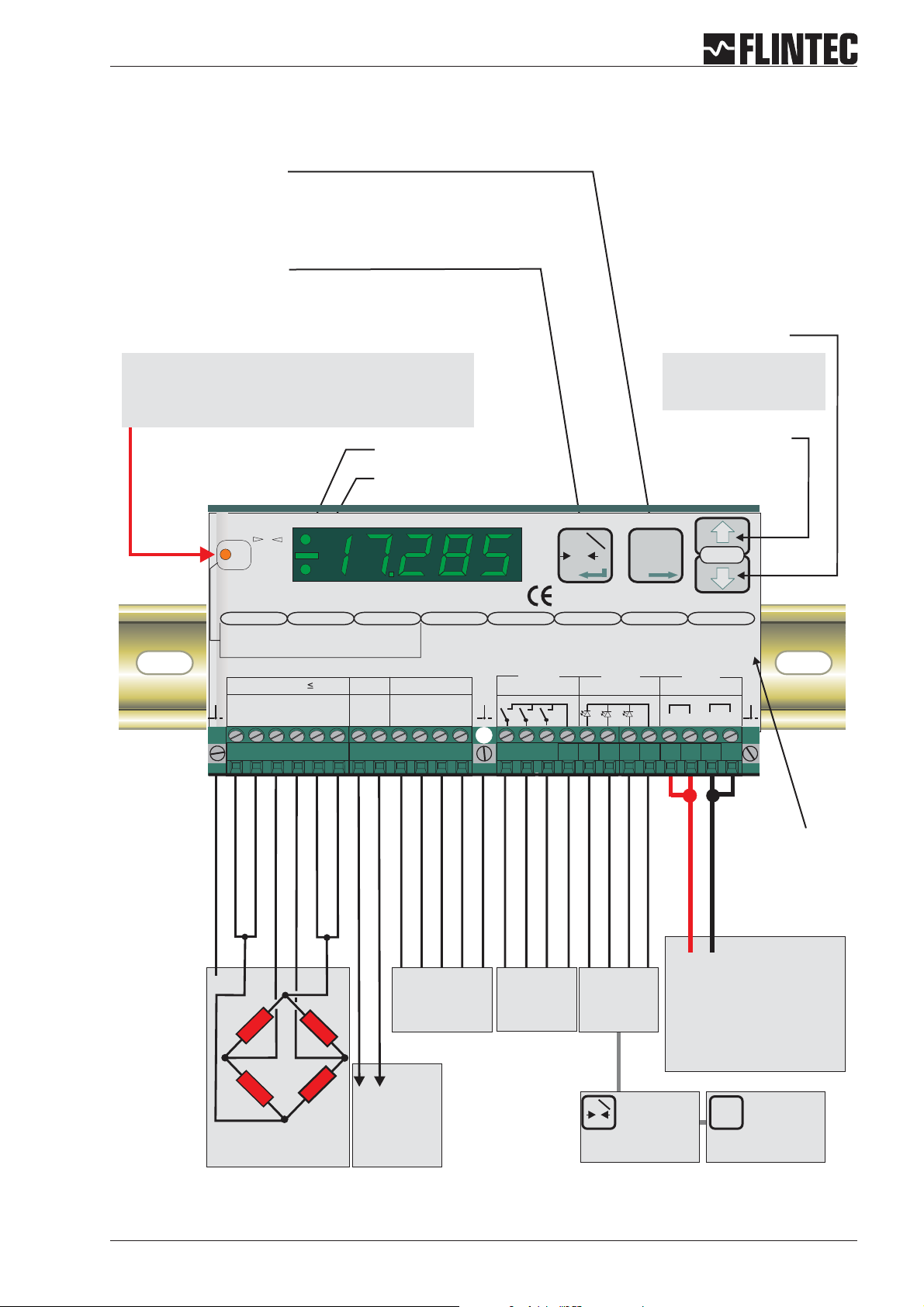
A.2 KEY FUNCTIONS
Tare Key
Puts unit into ‘Net’ mode.When inside
‘Set-up’ Menu this key moves the menu
back one step. Also moves‘Digit Selected’
to the right inside sub menus.
Zero Key
Sets new zero (if enabled). Reverts to calibrated zero
if the button is held down for more than 3 seconds.
Switches unit back to ‘Gross’ mode if a tare has been
set. Acts as the‘Enter’ key in the ‘Set-up’ Mode.
Down key
Recessed Enable Switch
(Enables changes to be made to important parameters.
Must be pressed before attempting to change
parameters 1.1 to 1.3, 2.1 to 2.3 and 3.1 to 3.3)
No motion LED
Net mode LED
Logic input 1 2 3
0
Depress
To
Change
Net
Logic output
1.Zero
1.0/allow>0<
2.Calibrate
3.Set mV/V
Load cell 5Vdc 80mA
Exc Sen Sig Sig Sen Exc Rx Rx Tx Tx
+++ +
2 3 4 5 6 7 8 9 10 111213
1
2.Span
1.Set cal. ´n´
2.Calibrate
3.Set mV/V
4.Disp.mV/V
--- -
123
3.Display
1.o/u limits´n´
2.Step * ´n´
3.Dec.point
4.Logic stats
0-20mA
Io Gnd
4.Filter
1.f Hz
cut
2.Algorithm
3.Update rate
4.
Motion´n´
RS422/485CL out
+
to enter the set up mode
7.Outp. 1/2/3
1.SPoint ´n´
2.Hyst. ´n´
3.Base
4.Test
Isolated
Mark III
T
T
T0
±
Isolated
Power 11 -25Vdc
+
+
SET UP
8.Datacom.
1.Baud rate
2.422/485
3.Address
4.Auto trnsm.
Digital Amplifier + Setpoint DAS 72.1
Inp.1 Inp.2
T
Isolated
6.Input 1/2/3
1.Assign key
2.
3.
4.Test
Logic Inputs
12 3com
5.CLout
1.4mA=´n´
2.20mA=´n´
3.Base
4.TestImA
Logic Outputs
12 3com
-
14 27
Press either key for
more than 3 seconds
Up key
0
0
261516 17 2324 25181920 2122
SHIELD
+ EXCITATION
+ SENSE
+SIGNAL
- SENSE
- SIGNAL
- EXCITATION
Receive -
Receive +
Ground
Transmit -
Transmit +
Logic Input 1 (+)
Logic Input 2 (+)
Logic Input 3 (+)
Commmon
“Set up”
menu structure
+0
RS422/485
COM port
Logic
outputs
+0
0 4-20mA
/
Load cell
connections
Manual DAS 72.1 Page 3
analogue
output
Logic
inputs
Input 1
Inp.1
T
(Functions as
0
Zero button,
Tare off, Set zero,
see paragraph B.3.6)
Power supply
12-25 V DC
Inp.2
Input 2
(Functions as
T
T
T
Tare button,
Display net mode,
see paragraph B.3.6)

B KEYBOARD SET UP
A GENERAL 2
A.1 INTRODUCTION AND SPECIFICATION 2
A.2 KEYFUNCTIONS 3
B KEYBOARDSET UP 4
B.1 SHORTMANUAL OF KEYBOARD SETUP 5
B.2 SETUPTABLE 6
B.3 SETUP FLOWCHARTS 7
B.3.1 Zeroset up,Menu 1.1 - 1.4 7
B.3.2 Spanset up,Menu 2.1 -2.4 8
B.3.3 Displayset up,Menu 3.1 - 3.4 9
B.3.4 Filter / no motion setup, Menu 4.1- 4.4 10
B.3.5 Analogueoutput set up, Menu 5.1- 5.4 11
B.3.6 Logicinput setup, Menu 6.1.3- 6.3.4 12
B.3.7 Logicoutput setup, Menu 7.1- 7.3 14
B.3.8 Datacommunication set up,menu 8.1 - 8.4 15
B.3.9 Errorcodes 16
B.4 EXAMPLES 17
B.4.1 Example1, calibration procedureusing weights 17
B.4.2 Example2, calibration procedureusing loadcell mV/V sensitivity and
B.4.3 Example3, calibration procedureusing loadcell mV/V sensitivity 21
D CE KONFORMITÄTSERKLÄRUNG 57
zero offset 19
Page 4 Manual DAS 72.1

B.1 SHORT MANUAL OF KEYBOARD SETUP
9600...115,2 k Baud
1. Setup Baudrate:
Setup setpoints
for outputs 1/2/3
1.1
• (00) not used
1. External Key control :
output of 4 mA
1. Setup value for an
• (01) Zero
Example:
2. Setup Mode for Com.
1.2 Setup switch logic
• (02) Tare
0.0 (g) @ 4 mA
ports
for:
Valid addresses
0...255
Address "0" device is
always active on bus
Address enable via
• RS-422 full duplex
• RS-485 Network
•
"open"
3. Setup Port Address
•
Example:
2. Setup Hysteresis of
• (06) Get average
• (07) Display Peak
1000 (g) @ 20 mA
setpoints
• (08) Delete Peak
• (09) Display Hold
output:
3. Base of analogue
• (0) Gross
3. Base of Outputs:
• (10) Peak to Peak
• Gross value
• (1) Net
• (11) Display Valley
• Nett value
• (12) Key lock
• Average valuet
• on
• off
• (03) Move up
• (04) Move down
• (05) External trigger
output of 20 mA
2. Setup value for an
• (2) Peak
• (3) Average
• (13) Store Weight
• Hold valuet
4. Auto Transmit of
• (14) Tare and delete
• Peak to Peak valuet
data:
• (4) Hold
• Valley valuet
• Gross
• (5) Peak to Peak
• Display value
2. not used
• Net
• (6) Valley
• Swiched off
• All (Data string)
• (7) Error 4 or 5
3. not used
• Sap (A/D value)
• (8) Swiched of
• Aver (Average
4. Test of Logic inputs
output signal
4. Simulate an analogue
value)
• Pea (Peak value
• Hold (Hold value)
The display shows
the signal status of
logic outputs
4. Test of Logic outputs
The display shows
the signal status of
logic inputs
Setup 12.345 for
getting an output
current of 12,345 mA
value)
• Vall (Valley value)
• Pp (Peak to Peak
• Off (switched off)
Standard display is
switched off!
Standard display is
switched off!
Setup menu : To enter, press one of the arrow keys for 3 seconds. To change calibration data, also press recessed switch (to the left of the display) once.
1. ZERO 2. Span 3. Display 4. Filter 5. CL out 6. Input 1/2/3 7. Output 1/2/3 8. Data Com
1. 0 / allow >O< 1. Set cal.”n” 1. o/u limits ‘n’ 1. f-cut Hz 1. 4 mA=’n’ 1. Assign key 1. SPoint ‘n’ 1. Baud rate
2. Calibrate 2. Calibrate 2. Step*’n’ 2. Algorithm 2. 20 mA=’n’ 2. 2. Hyst +/- ‘n’ 2. 422/485
3. Set mV/V 3. Set mV/V 3. Dec.point 3. Update rates 3. Base 3. 3. Base 3. Address
4. Tare Memory 4. Disp. mV/V 4. Logic stats 4. Motion ‘n’ 4. Test I mA 4. Test 4. Test 4. Auto trnsm.
adjustable from
1=18Hzto
1. Cut off frequency
at which the display
shows an overload (o)
1. Measured value
actual measured
signal after 2.2 or
1. Calibration value for
Zero lock / unlock
1. Zero Tracking or Set
8 = 0.25 Hz
or an underload (u)
with internal mV/V
2. Calibrate Zero with
Typical setup:
signal after 2.3
should be displayed
actual or external
"4"=3 Hz
2. Display step size as
simulated input
signal changes
• FIR-Filter for quick
dampening
• IIR-Filter for high
2. Select Filter Type:
1, 2, 5, 10, 20 etc
point of the display
Example:
000.00 @ 100.00(g)
3. Position decimal
Example: 10 000 (g)
cell(s) connected or
will be simulated by a
simulator
This signal refers to
2. Input signal of load
signal
display "Zero” with
manual setup of
mV/V signal
3. Calibrate Zero to
This setup has
additional influence
•
on filters
3. Update rate
status
• No Status I/O
(approx 1,5 s)
• Short display of
for in motion band
(Tare, Zero and
Zero Tracking are
only allowed at
4.1 No Motion Range
4.2 Stabilisation time
I/O
• Permenant status
"No Motion")
4. Display I/O:
calibrate value of
setup 2.1
4.1 Tare "ON":= Tare
value stred
3. Input signal in mV/
non-volatile
Tare "OFF": Tare
setupwiththefront
panel keys
This signal refers to
calibrate value of
setup 2.1
1,6500 mV/V @ 1000
(g)
input signal in mV/V
For test purposes
4. Display of actual
value deleted at
power off
"ON" Load cells
connected with
Zener barriers
"OFF" Load cells
connected without
Zener barriers
4.2 EX-Modus
Manual DAS 72.1 Page 5

B.2 SETUP TABLE
Description
Function Zero key (on/off))
Zero Calibration / Weight
Zero Calibration / mV/V
Span / Weight or mV/V
Span / Weight
Span / mV/V
Displays Actual mV/V Signal
Maximum Display Value
Maximum Display Value
Display Step Size
Decimal Point Position
Display Status I/O
Cut Off Filter Frequency
Filter Type
Update Rate per second (filtered)
No Motion Range
Set Analogue Output @ 4 mA
Set Analogue Output @ 20 mA
Base of Analogue Output
Simulate Analogue Output Signal
Input 1 for External Key Control
Input 2 for External Key Control
Input 3 for External Key Control
Read Iinput Status
Base of Digital Inputs
Test Logic Inputs
Output Setpoint 1
Output Setpoint 2
Output Setpoint 3
Hysteresis & Logic Setpoint 1
Hysteresis & Logic Setpoint 2
Hysteresis & Logic Setpoint 2
Base Setpoint 1
Base Setpoint 2
Base Setpoint 3
Function Test Output 1
Function Test Output 2
Function Test Output 3
Baudrate RS-422/485 Port
Port Mode (422 or 485)
Device Address Com Port
Auto Transmit Data
LED Display Pre Setup Example: 3000 kg scale
with 0.5 kg step
Menu Point Value Value Result
<1.1>
<1.2>
<1.3>
<2.1>
<2.2>
<2.3>
<2.4>
< 3.1.o >
< 3.1.u >
<3.2>
<3.3>
<3.4>
<4.1>
<4.2>
<4.3>
<4.4>
<5.1>
<5.2>
<5.3>
<5.4>
< 6.1.1 >
< 6.2.1 >
< 6.3.1 >
<6.2>
<6.3>
<6.4>
< 7.1.1 >
< 7.2.1 >
< 7.3.1 >
< 7.1.2 >
< 7.2.2 >
< 7.3.2 >
< 7.1.3 >
< 7.2.3 >
< 7.3.3 >
< 7.1.4 >
< 7.2.4 >
< 7.3.4 >
<8.1>
<8.2>
<8.3>
<8.4>
0-oFF
0.000
0.000
20000
0.000
2.000
--
99999
-9999
1
0
1
33.3
FIR
3
1
00000
20000
gross
--
--
--
--
--
--
-99999
00000
oFF
--
--
--
--
--
--
--
--
--
9600
422
0
oFF
0-oFF
0.000
0.400
a)3000.0 or
b)750.0
0.9
2.000
--
3100.0
-200.0
5
0.0
1
3.0
FIR
3
1
0.0
3000.0
gross
--
--
--
--
--
--
--
0000.0
1000.0
3000.0
0000.0
0000.0
0000.0
net
net
net
--
--
--
9600
422
0
nEt
Set zero not
possible
kg
mV/V
Cal. with mV/V
Cal. with 750 kg
mV/V
mV/V
-kg
kg
0,5 kg
0000.0
Status for 1 s
Hz
for quick signal
changes
measurements/s
kg
kg
gross
--
--
--
--
--
--
-kg
kg
kg
kg
kg
kg
net
net
net
--
--
--
Baud
422-Port
Device No.
auto transmit
net weight
Page 6 Manual DAS 72.1
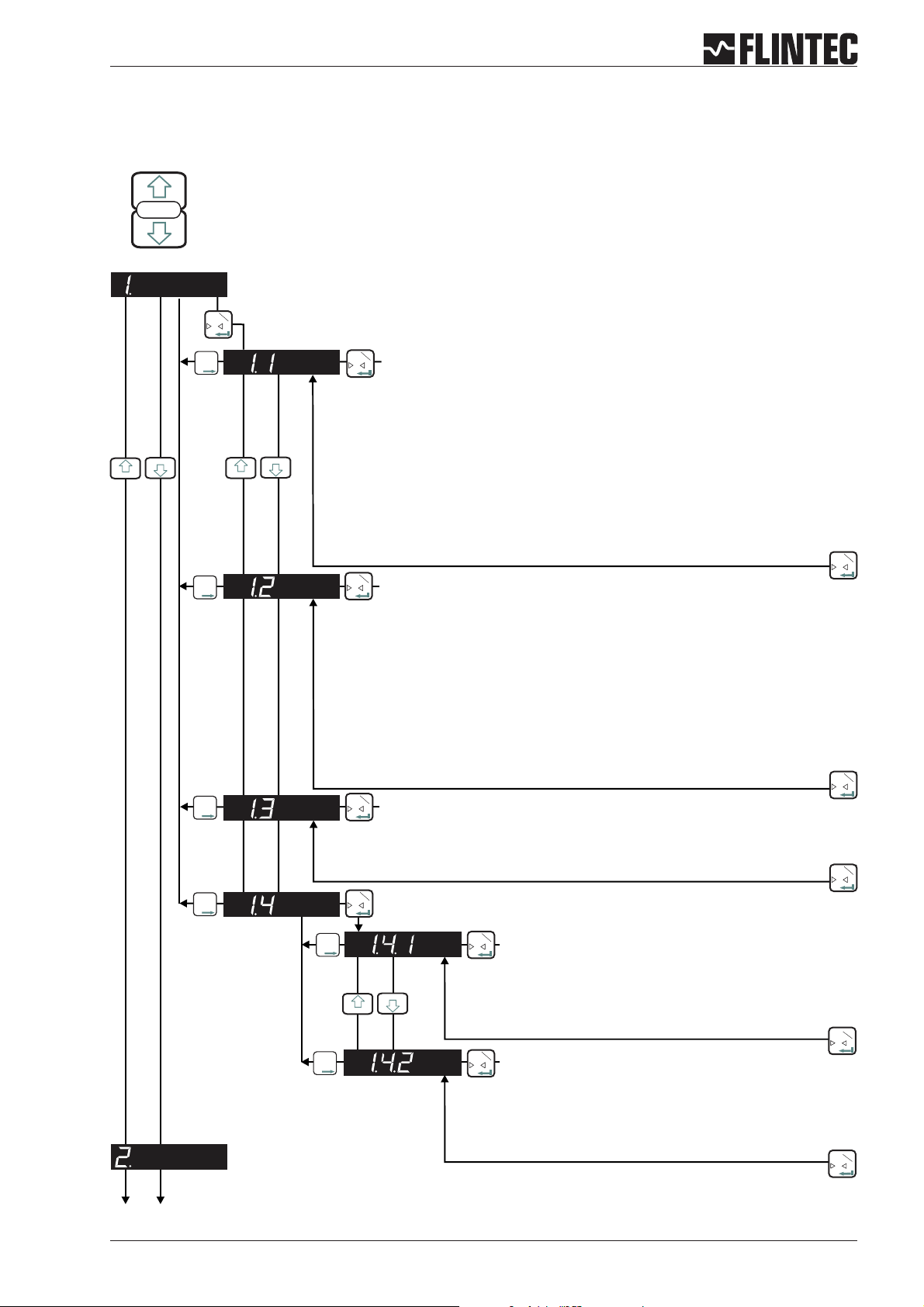
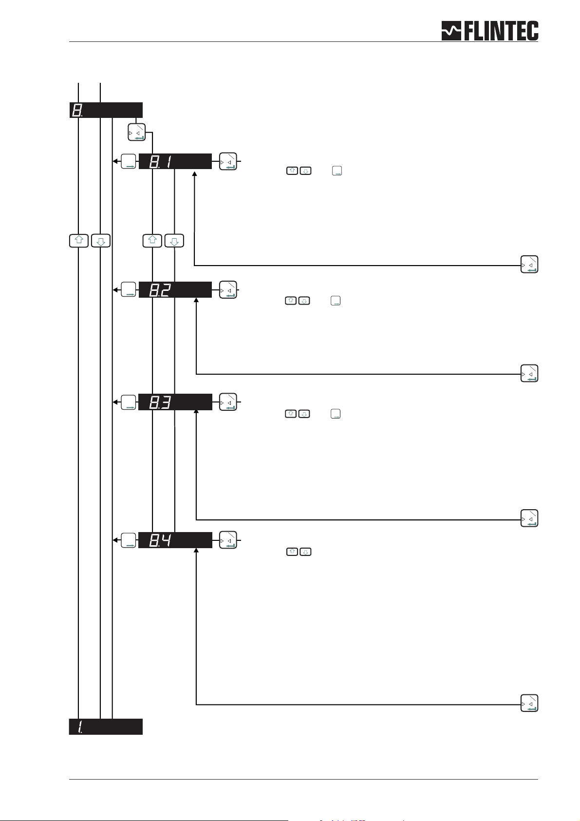
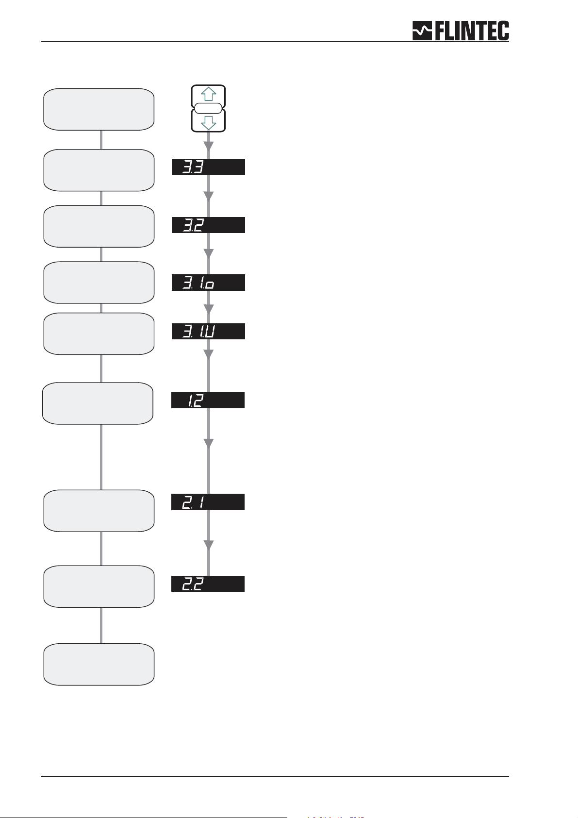
B.3 SET UP FLOWCHARTS
B.3.1 Zero set up, Menu 1.1 - 1.4
SET UP
Press the UP or DOWN key
for more than 3 seconds to enter the Set-up Menu
Inp.1
T
0
Inp.2
T
T
T
Inp.1
T
Automatic Zero Tracking
0
Settings: 0 ... 255 d
Function is swiched off at setting 00 000.
Zero Setting with zero key or by external signal is not possible (Menu 6).
Function is swiched on at setting 00 001 or higher, (max 00 255).
Zero Setting with zero key or by external signal (Menu 6).
Setting 00 001 sets a zero range of +/-2%ofUpper Display Limit (Menu 3.1),
setting 00 002 up to 00 255 sets a range of2dupto255d(independant of
decimal point setting).
Inp.2
T
T
T
Inp.1
T
0
CALIBRATE OR ADJUST THE ZERO POINT
(CONVENTIONAL WEIGHING SYSTEM)
Display shows the actual input signal in mV/V.
Press the Enter key to store the zero.
Note:
Recessed Enable Switch
(Enables changes to be made
to important parameters.
Must be pressed before
attempting to change parameters
1.1 to 1.3, 2.1 to 2.3 and 3.1 to 3.3)
Inp.1
T
0
Remark:
Inp.2
T
T
T
Inp.1
T
0
CALIBRATE THE ZERO POINT FROM THE LOAD CELL mV/V READING
scale should be unloaded.
Inp.1
T
0
Use the UP/DOWN & MOVE RIGHT keys to set the mV/V reading at which the
unit should read zero.
Inp.2
T
T
T
Inp.1
T
0
Inp.2
T
T
T
Inp.1
T
0
Store Tare value, setting ON or OFF
Inp.1
T
0
OFF: Tare value deleted at power off
ON: Tare value stored non-volatile (max. 1 000 000 times)
Inp.1
T
Inp.2
T
T
T
Inp.1
T
0
EX-Modus, setting ON or OFF
0
OFF:Load cell connection without Zener barrieres
ON: Load cell connection with Zener barrieres,
extended error band for ERR 5
Inp.1
T
0
Manual DAS 72.1 Page 7
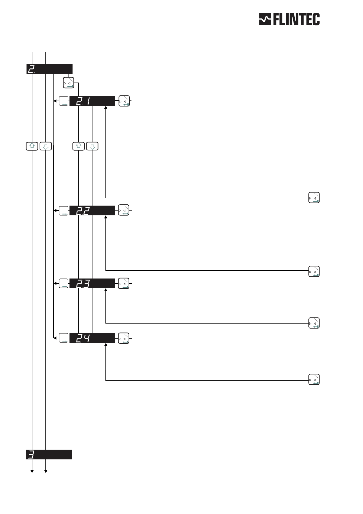
B.3.2 Span set up, Menu 2.1 - 2.4
Inp.1
T
0
Inp.2
T
T
T
Inp.1
T
SET THE SPAN CALIBRATION VALUE
0
Twopossibilities areavailable:
A. Setthe displayvalue equivalent to thecalibration weight,continue withstep 2.2
or
B. Use the mV/Vsignal derivedfrom the load cell(s)test data,continue withstep 2.3.
Inp.1
T
0
Inp.2
T
T
T
Inp.1
T
0
CALIBRATE THE SPAN (CONVENTIONAL WEIGHING SYSTEM)
Display shows the actual input signal in mV/V.
Apply test weights equivalent to the calibration value set in section 2.1. Press the Enter
key to store the new span value.
Inp.1
T
Inp.2
T
T
T
Inp.1
T
CALIBRATE THE SPAN FROM THE LOAD CELL mV/V READING
0
0
Use the UP/DOWN & MOVE RIGHT keys to set the mV/V reading at which the unit should
read the value set in section 2.1.
Inp.1
0
Inp.2
T
T
T
Inp.1
T
0
DISPLAY THE INPUT SIGNAL IN mV/V
This function allows you to view the input signal in mV/V.
Inp.1
0
Page 8 Manual DAS 72.1
T
T
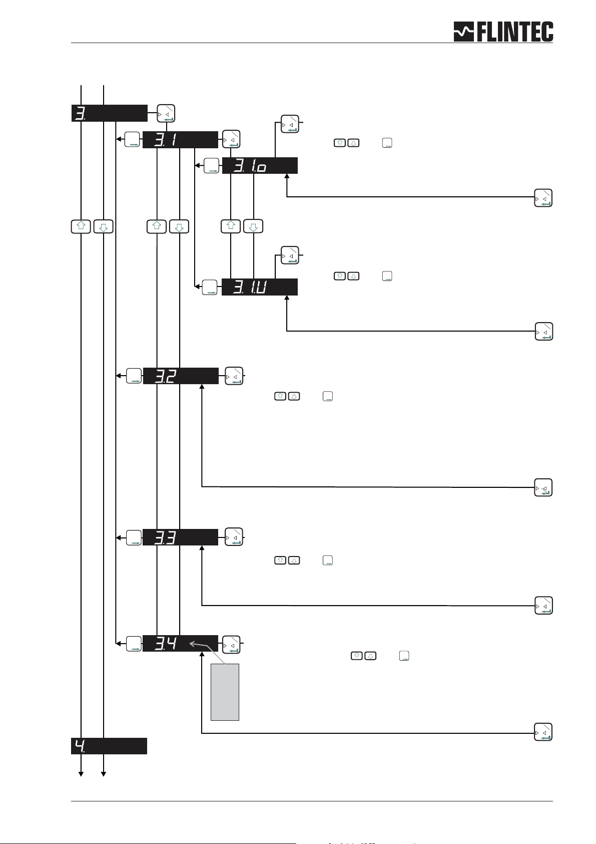
B.3.3 Display set up, Menu 3.1 - 3.4
Inp.1
T
0
Inp.2
T
T
T
Inp.1
T
0
Inp.2
T
T
T
Inp.2
T
T
T
Inp.1
T
SET THE DISPLAY OVER RANGE LIMIT
0
(MAXIMUM VALUE +99 999)
Use the and keys to set the maximum display value
Inp.2
T
T
T
above which the display shows over range (all dashes in the top of the
display).
Inp.1
T
SET THE DISPLAY UNDER RANGE LIMIT
0
(MINIMUM VALUE -99 999)
Use the and keys to set the minimum display value
Inp.2
T
T
T
below which the display shows under range (all dashes in the bottom
of the display).
Inp.1
T
0
Inp.1
T
0
Inp.2
T
T
T
Inp.2
T
T
T
Inp.1
T
SET THE DISPLAY DIVISION OR STEP SIZE
0
(1, 2, 5, 10, 20, 50, 100, 200, 500)
Use the and keys to set the required display division or step size.
Inp.1
T
0
SET THE DECIMAL POINT POSITION ON THE DISPLAY
(0, 0.0, 0.00, 0.000, 0.0000)
Use the and keys to set the required decimal point position on the
Inp.2
T
T
T
Inp.2
T
T
T
Inp.1
T
0
display.
Inp.1
T
0
Inp.2
T
T
T
Inp.1
3.4.0
T
LOGIC I-O STATUS
0
Select setting 0, 1 or 2 with and .
Inp.2
T
T
T
Setting 0 = Continious indication of Weight, no input/output status.
Setting 1 = Indication of Weight, short indication input/output status (ca. 1,5 sec)
3.4.1
Setting 2 = Continious indication of input/output status.
3.4.2
Inp.1
T
0
Manual DAS 72.1 Page 9
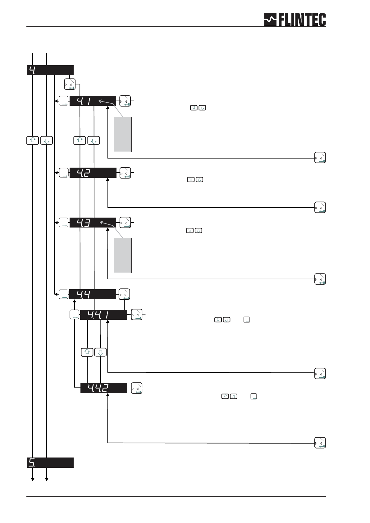
B.3.4 Filter / no motion set up, Menu 4.1 - 4.4
Inp.1
T
0
Inp.2
T
T
T
Inp.2
T
T
T
Inp.2
T
T
T
Inp.2
T
T
T
Inp.1
0
4.1.0
:
:
:
4.1.8
Inp.1
0
Inp.1
0
4.3.0
:
:
:
4.3.7
Inp.1
0
T
Set the low pass filter cut off frequency
Set Range: 0 - 8 with
Filter setting 18 Hz (4.1.1) to 0.25 Hz (4.1.8) with Filter type IIR.
Filter setting 19.7 Hz (4.1.1) to 2.5 Hz (4.1.8) with Filter type FIR.
Attention
See Paragraph C.4.5 for more information.
T
Set the type of low pass filter required
: FIR or IIR
Setting with
Type IIR should be used where heavy damping is required.
Type FIR should be used where high speed is required.
T
Defines the number of filtered readings averaged
Set Range: 0-7mit
This Parameter defines the number of Readings from the IIR or FIR filter that
will be averaged.
Selection between “0” (1 Reading) and “7” (128 Readings).
Attention:
T
: Setting
“0” (4.1.0) deactivates the Filter.
See Paragraph C.4.5 for more information.
Inp.1
T
0
Inp.1
T
0
Inp.1
T
0
Inp.2
T
T
T
Inp.1
T
Set the No Motion Range
0
Set Range: 0 - 30 000 steps and
Inp.2
T
T
T
Fluctuations in weight values inside this range will be considered as
‘stable’.
Attention:
See also 4.4.2 for the Stabilisation Time
If the condition of the No Motion Range is fullfilled within the Stabilistion
Time the “No Motion” status bit will be set to allow zero setting, taring as
well as calibrating zero and span.
Inp.1
T
0
Inp.1
T
0
Set the Stabilisation Time
Set Range: 0 - 30 000 mS with and
Inp.2
T
T
T
Sets the Stabilisation Time in milliseconds within which the weight value
displayed has to remain within the No Motion Range, for the weigh to be
considered ‘stable’.
Inp.1
T
0
Page 10 Manual DAS 72.1

B.3.5 Analogue output set up, Menu 5.1 - 5.4
Inp.1
T
0
Inp.2
T
T
T
Inp.1
T
Set the weight value at which 4 mA is send
0
Setting with and
Inp.2
T
T
T
Set the weight value at which 4 mA is send.
Examples:
Weighing range 3 000 kg and 3 000 d with 0/4...20 mA.
Analogue output 4...20 mA: for 0 kg=4mAmake setting 00 000.
Analogue output 0...20 mA: for 600 kg=4mAmake setting 00 600.
Inp.1
T
0
Inp.2
T
T
T
Inp.1
T
Set the weight value at which 20 mA is send
0
Setting with and
Inp.2
T
T
T
Set the weight value at which 20 mA is send.
Examples:
Weighing range 3 000 kg and 3 000 d with 0/4...20 mA.
Analogue output 4...20 mA: for 3 000 kg = 20 mA make seting 03 000.
Analogue output 0...20 mA: for 3 000 kg = 20 mA make seting 03 000.
Inp.2
T
T
T
Inp.1
T
Set the analogue output base
0
Setting with and for the following values:
GROS Gross
NET Net
PEA Peak
AVER Average
HOLD Hold
PP Peak÷Peak
VALL Valley
DISP Display
OFF OFF
= Analogue output follows value
= Analogue output follows value
= Analogue output follows value (maximum)
= Analogue output follows value
= Analogue output follows value
= Analogue output follows value
= Analogue output follows value (minimum)
= Analogue output follows value
= Analogue output is switched
Inp.2
T
T
T
Inp.1
T
0
Inp.1
0
Inp.2
T
T
T
Inp.1
T
0
Test the current output
Set Range 0...20 mA with . And
Inp.2
T
T
T
Set a current value in mA, which will be sent down the analogue output,
independent of the load applied to the weighing system.
Inp.1
0
Manual DAS 72.1 Page 11
T
T
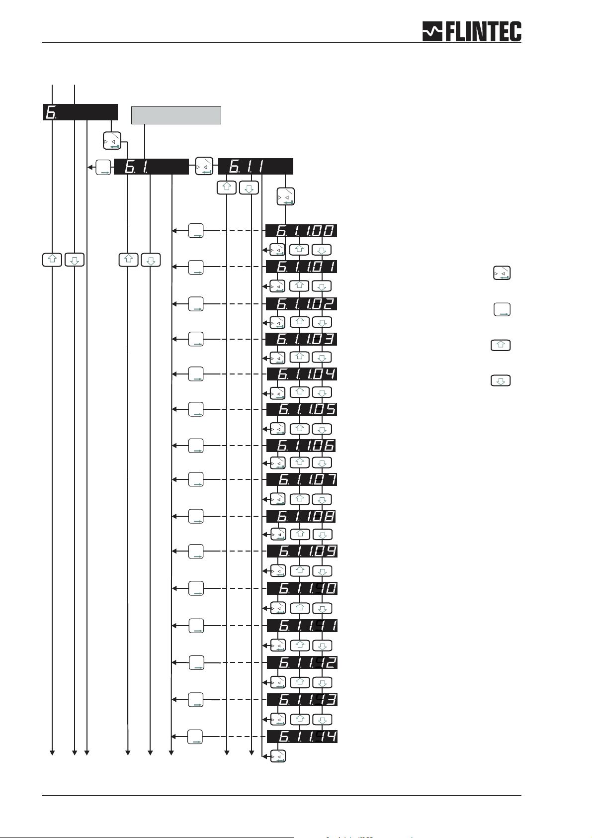
B.3.6 Logic input set up, Menu 6.1.3 - 6.3.4
The second digit coresponds
with the input number
1
T
0
2
T
T
T
1
T
0
Set the function for Logic Input “1”
Possible settings: 00, 01 ,02 ,03 ,04 ,05 ,06 ,07, 08, 09,
10, 11, 12, 13, 14.
1
T
0
12
3
56
4
Fortsetzung nächste Seite
2
T
T
T
1
T
0
2
T
T
T
1
T
0
2
T
T
T
1
T
2
T
T
T
2
T
T
T
2
T
T
T
2
T
T
T
2
T
T
T
2
T
T
T
2
T
T
T
2
T
T
T
2
T
T
T
2
T
T
T
2
T
T
T
2
T
T
T
7
0
1
T
0
1
T
0
1
T
0
1
T
0
1
T
0
1
T
0
1
T
0
1
T
0
1
T
0
1
T
0
1
T
0
8
1
T
0
Input “1” no function
Input “1” acts as Zero button
Input “1” acts as Tare button
1
T
0
2
T
T
T
Input “1” acts as Up arrow button
Input “1” acts as Down arrow button
Input “1” starts the Trigger function
Input “1” displays the Average value
Input “1” displays the Peak value (maximum)
Input “1” deletes the Peak value
Input “1” displays the Hold value
Input “1” displays the Peak to Peak value
Input “1” displays the Valley value (minimum)
Input “1” disables the keyboard
Input “1” stores the actual weight (Hold value)
Input “1” tares the display and deletes all other
values like 6.1.1.08
Page 12 Manual DAS 72.1
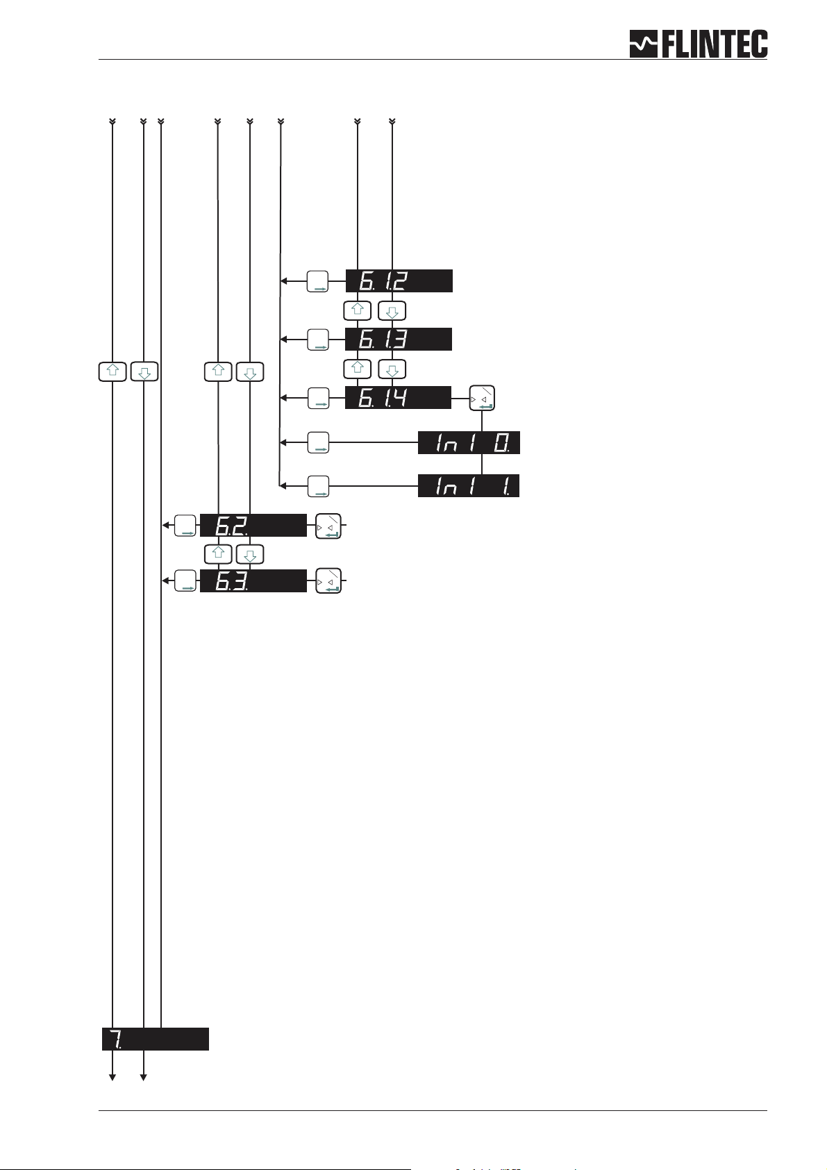
Logic input set up, Menu 6.1.3 - 6.3.4 (continued)
12
3
56
4
2
T
T
T
2
T
T
T
2
T
T
T
2
T
T
T
2
T
T
T
2
T
T
T
1
T
0
8
7
No function
No function
1
T
0
Check Logic Input “1”
(6.1.1. must be set to “0” => 6.1.1.0)
“In1 0.” Input is ”low”
“In1 1.” Input is ”high”
As per section 6.1 but for Logic Input “2”
2
T
T
T
1
T
As per section 6.1 but for Logic Input “3”
0
Manual DAS 72.1 Page 13
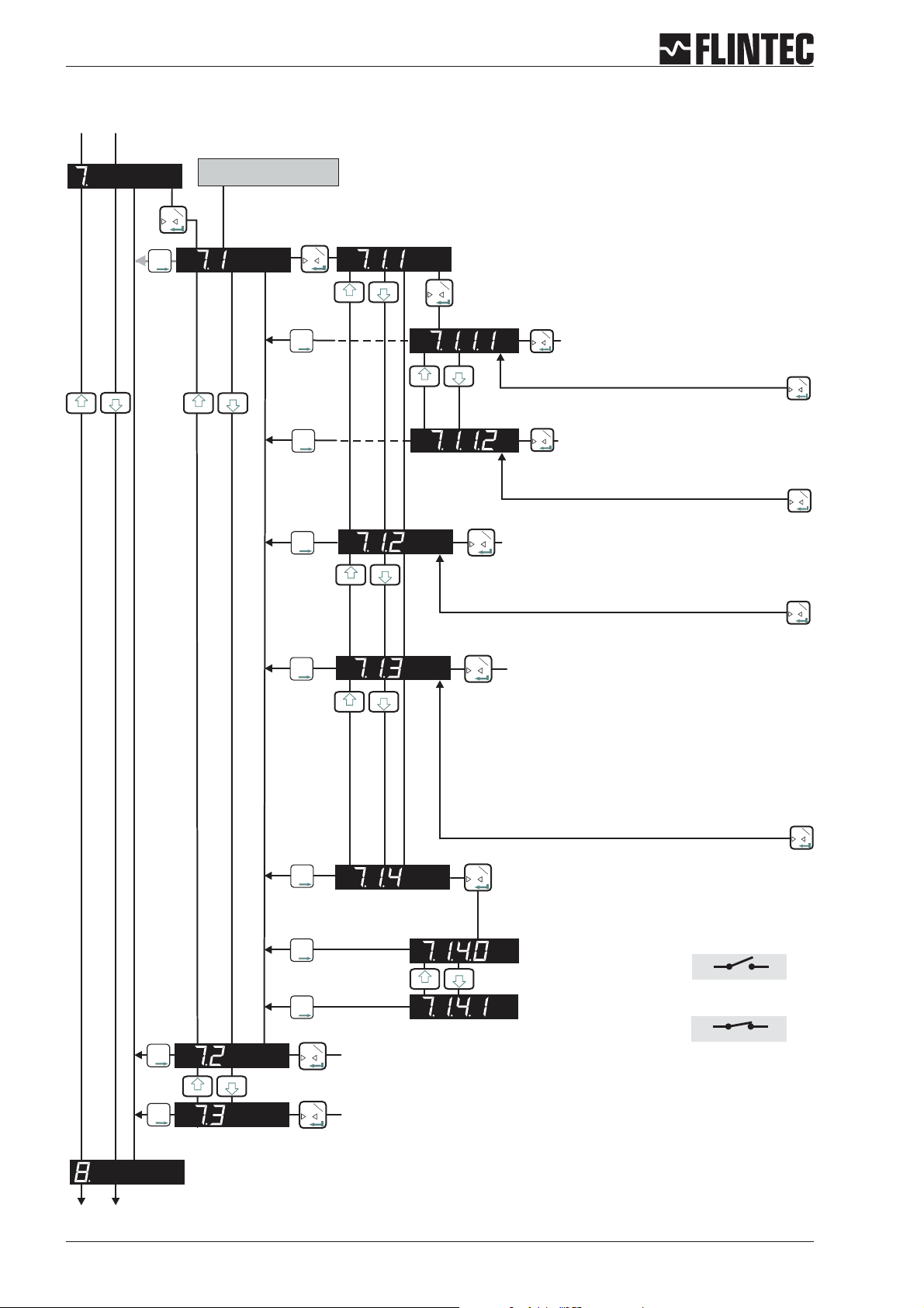
B.3.7 Logic output set up, Menu 7.1 - 7.3
The second digit coresponds
with the output number
1
T
0
2
T
T
T
1
T
0
2
T
T
T
2
T
T
T
2
T
T
T
Set the function for Logic Output “1”
1
T
0
Set weight value at which Logic
1
T
Output “1” switches
0
Permitted values +/- 99 999
1
T
0
Set whether Logic Output “1”
1
switches ON or OFF
T
0
Use the UP/DOWN keys to set whether
logic output 1 switches ON or OFF at the
1
T
0
Set the hysteresis value on the setpoint for
1
T
0
Logic Output “1”
Permitted values +/- 99 999.
1
T
0
Set base for Logic Output “1”
2
T
T
T
2
T
T
T
2
T
T
T
2
T
T
T
2
T
T
T
1
T
0
As per section 7.1 but for Logic Output “2”
1
T
0
GROS Gross
NET Net
PEA Peak
AVER Average
HOLD Hold
PP Peak to Peak
VALL Valley
ERR Error
OFF OFF
Check Logic Output “1”
1
T
Use the UP/DOWN keys to switch.
0
= value
= value
= value (maximum)
= value
= value
= value
= value (minimum)
= 4 or 5
= Sets output
The output is “off”.
The output is “on”.
out 1
out 1
com
com
1
T
0
2
T
T
T
1
T
As per section 7.1 but for Logic Output “3”
0
Page 14 Manual DAS 72.1
B.3.8 Data communication set up, menu 8.1 - 8.4
Inp.1
T
0
Inp.2
T
T
T
Inp.1
T
Set the Baud Rate for COMPORT (RS-422/485)
0
Setting with and
Inp.2
T
T
T
9 600 Baud
19 200 Baud
38 400 Baud
57 600 Baud
115 200 Baud
Inp.1
T
0
Inp.2
T
T
T
Inp.1
T
Select either RS-422 or RS-485
0
Setting with and
Inp.2
T
T
T
422 = RS-422-Interface (use for single DAS application)
485 = RS-485-Interface (use for multiple DAS application in BUS)
Inp.1
T
0
Inp.2
T
T
T
Inp.1
T
0
Set the Device Address Comport (RS-422/485)
Setting with and
Inp.2
T
T
T
Set the device address for multi-drop to 001 ... 255.
Set to 000 for single point to point applications.
Inp.1
0
Inp.2
T
T
T
Inp.1
T
0
Select the Autotransmit Mode
Setting with
GROS
NET
ALL
SAP
AVER
PEA
HOLD
VALL
PP
OFF
= Gross value
= Net value
= Data string with Gross, Net and Status
= A/D value
= Average value
= Peak value (maximum)
= Hold value
= Valley value (minimum)
= Peak to Peak value
= Autotransmit OFF
Inp.1
0
Manual DAS 72.1 Page 15
T
T
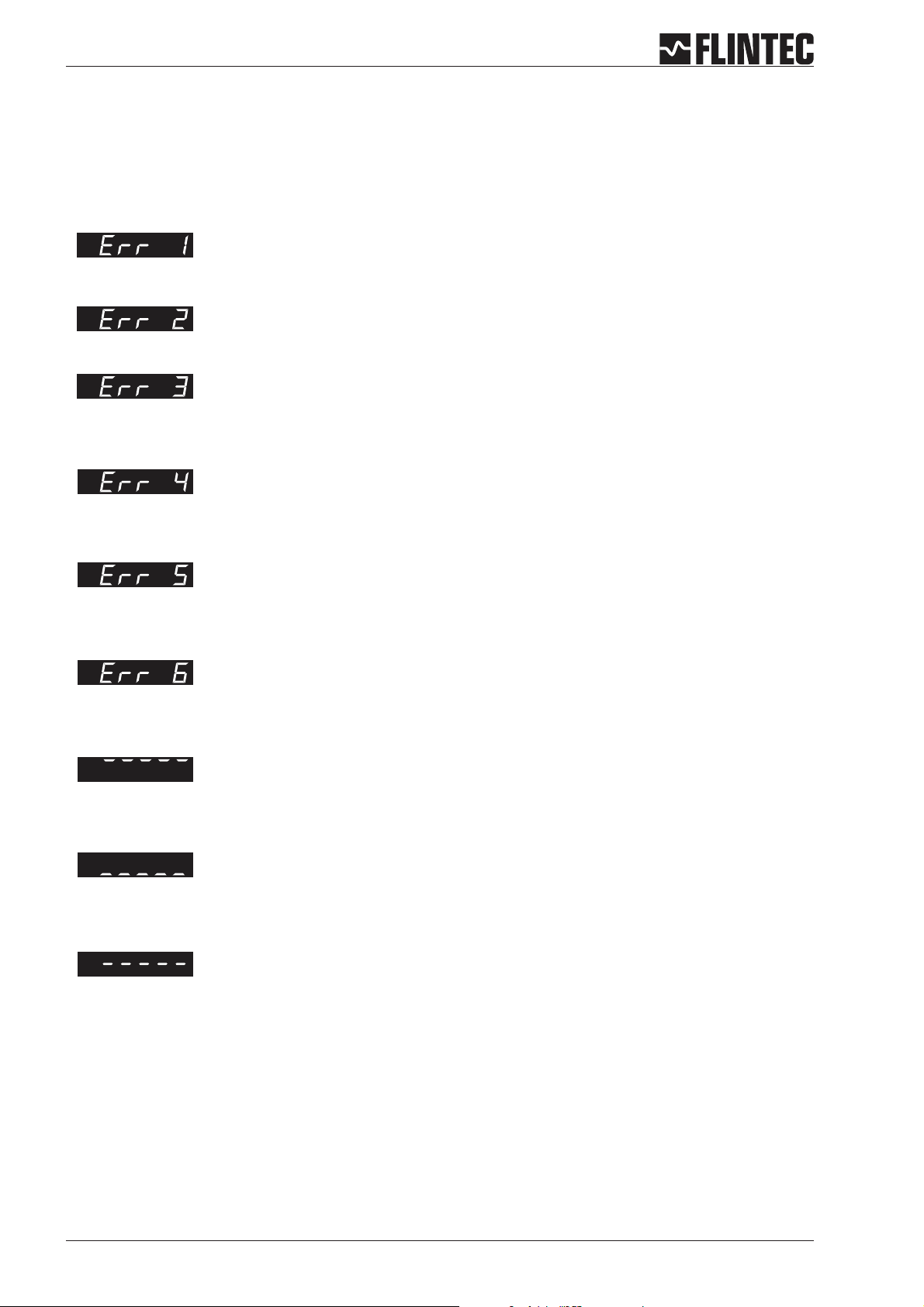
B.3.9 Error codes
The zero key is not enabled (See menu 1.1)
Set final zero out of range.
(You are trying to set a zero which is greater than ±2% of the Upper Display Limit)
Excessive sensitivity requested.
(The input signal is being divided into too many divisions i.e the size of each division is < 0.5 V)m
The input signal is in excess of ± 2.6 mV/V
Faulty load cell connection (Open circuit / Short Circuit / Wire disconnected)
You are trying to enter a value which is not valid (Outside the acceptable parameter range)
Display overload (Display value exceeds the upper limit set in Menu 3.1.o)
Display underload (Display value is more negative than the lower limit set in Menu 3.1.U)
The Zero or Tare motion limit has been exceeded. Set Zero or Tare function disallowed.
Review Zero and Tare motion limits set in menu 4.4
Remark
If you need to return the DAS72.1 Mark III to the factory settings simply press and hold the recessed enable switch whilst
powering up the unit. All parameters will then revert to the factory settings
Page 16 Manual DAS 72.1
B.4 EXAMPLES
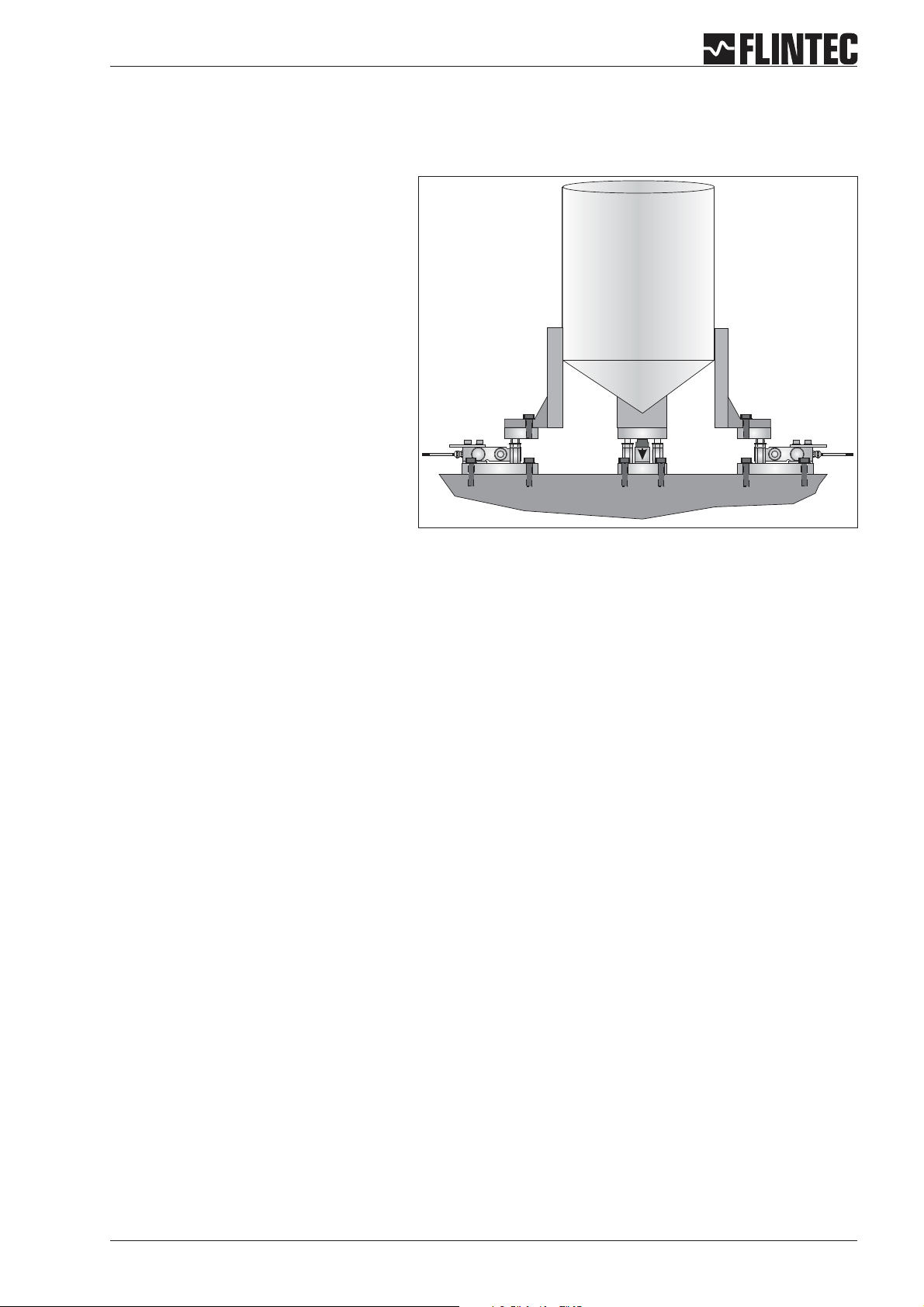
B.4.1 Example 1, calibration procedure using weights
3 Leg tank or silo fitted with 3 off 1000 kg
@ 2 mV/V load cells.
Dead load 600 kg.
Live range 2000 kg in 0.5 kg steps.
It is assumed that the load cell system is
connected to the DAS72.1 and the power
is on. The maximum and minimum display
values, display increment size and decimal
point position should be defined prior to
carrying out the calibration (See Menu 3).
For this example the display maximum is
defined as 2100.0, the display minimum is
-200.0, the display step size is 0.5 kg.
Remember that all parameters under
sections 1.1 - 1.3, 2.1 - 2.3 and 3.1 - 3.3 can only be accessed or changed after the Recessed Enable
Switch has been pressed.
Go to Menu 1.2 and using the UP/DOWN and RIGHT keys set the display to read 0000.0. Make sure that the
a
weighing system is empty or at the point where you want the display to read zero. Press the 0 [Enter] key.
This defines the actual zero calibration point.
b
Go to Menu 2.1 and using the UP/DOWN and RIGHT keys set the display to read the value of the calibration
weight(s) applied. For this example if the calibration load applied is 750 kg set the display to read 750.0.
Press the 0 [Enter] key. This defines the calibration weight.
c
Go to Menu 2.2.Apply the calibration weight(s) to the weighing system. Press the 0 [Enter] key. The display
will show the actual input signal in mV/V. Press the 0 [Enter] key. This defines the actual span calibration
point.The displaywill show 2.2. Press the rightarrow keytwice and the DAS willbe back in weighing mode.
Calibration is now completed.
Manual DAS 72.1 Page 17
Flowchart Example 1
Enter the
Set-up menu
Set the decimal
point position
Set the
display
step size
Set the Display
Upper Limit
(Overload)
Set the Display
Lower Limit
SET UP
1. Press the UP or DOWN key for more than
3 seconds to enter the Set-up Menu
2. Press the recessed enable switch
SET THE DECIMAL POINT POSITION (0, 0.0, 0.00, 0.000, 0.0000)
Use the UP or DOWN key to set the required decimal point position.
Choose 0.0
SET THE DISPLAY STEP SIZE. (1, 2, 5, 10, 20, 50, 100, 200, 500)
Use the UP or DOWN key to set the required display step size.
SET THE DISPLAY OVER RANGE LIMIT. (MAX. VALUE +99999)
Use the UP/DOWN & MOVE RIGHT keys to set the maximum display value
above which the display shows over range
(all dashes in the top of the display).
SET THE DISPLAY UNDER RANGE LIMIT. (MIN. VALUE -99999)
Use the UP/DOWN & MOVE RIGHT keys to set the minimum display value
below which the display shows under range
(all dashes in the bottom of the display).
Calibrate the
Zero point
Set the Display value
equal to the
Calibration weight
Calibrate
the Span
Calibration
completed
CALIBRATE THE ZERO POINT. (CONVENTIONAL WEIGHING SYSTEM)
Display shows the actual input signal in mV/V.
SET THE SPAN CALIBRATION VALUE.
Use the UP/DOWN & MOVE RIGHT keys to set the display value equivalent
to the calibration weight, e.g. 750 kg.
CALIBRATE THE SPAN. (CONVENTIONAL WEIGHING SYSTEM)
Display shows the actual input signal in mV/V. Apply test weights equivalent
to the calibration value set in section 2.1.
Press the Enter key to store the new Span value
Note:
Choose Filter type IIR (menu 4.2), Low Pass Filter 6 ... 8 (menu 4.1)
and wait for ‘No Motion’ in the calibration routine.
Page 18 Manual DAS 72.1

B.4.2 Example 2, calibration procedure using load cell mV/V sensitivity and zero offset
3 Leg tank or silo fitted with 3 off
1000 kg @ 2mV/V load cells
Dead load 600 kg.
Live range 2000 kg in 0.5 kg steps.
It is assumed that the load cell system is
connected to the DAS72.1 and the power is
on. The maximum and minimum display
values, display increment size and decimal
point position should be defined prior to
carrying out the calibration (See Menu 3).
For this example the display maximum is
defined as 2100.0, the display minimum is
-200.0, the display step size is 0.5 kg.
Remember that allparameters undersections 1.1 - 1.3, 2.1 - 2.3 and3.1 -3.3 can only be accessed or changed
after the Recessed Enable Switch has been pressed.
Go to Menu 1.3. and using the UP/DOWN and RIGHT keys to set the zero point of the 3 load cells to 0.0000
a
mV/V. Press the 0 [Enter] key. This defines the theoretical zero calibration.
b
Go to Menu 2.1 and using the UP/DOWN and RIGHT keys set the display to read the capacity of the load cell
system or the weight value at which the sensitivity is known. For this example the load cell capacity is 3 x
1000 kg = 3000 kg @ 2 mV/V. Set the display to read 3000.0. Press the 0 [Enter] key. This defines the
theoretical calibration weight (equivalent to 2mV/V in this example).
c
Go to Menu 2.3. Press the 0 [Enter] key. Use the UP/DOWN and RIGHT keys set the display to read the mV/V
sensitivity of the load cell system you are using.For this example the load cell sensitivity or Output at Rated
Load is 2.000 mV/V. In multiple load cell installations (load cells wired in parallel) the sensitivity is the
average of all the load cells connected. Press the 0 [Enter] key. This defines the theoretical span calibration
point.
d
If required the zero can be re-calibrated without affecting the span. To do this make sure that the weighing
system is empty or at the point where you want the display to read zero. Goto Menu 1.2. Press the 0 [Enter]
key. The display shows the actual input signal in mV/V. Press the 0 [Enter] key. Press the right arrow key
twice and the DAS will be back in weighting mode.
Calibration is now completed.
Manual DAS 72.1 Page 19

Flowchart Example 2
Enter the
Set-up menu
Set the decimal
point position
Set the
display
step size
Set the Display
Upper Limit
(Overload)
Set the Display
Lower Limit
Set Zero of load cells
mV/V sensitivity
for Zero point
SET UP
1. Press the UP or DOWN key for more than
3 seconds to enter the Set-up Menu
2. Press the recessed enable switch
SET THE DECIMAL POINT POSITION (0, 0.0, 0.00, 0.000, 0.0000)
Use the UP or DOWN key to set the required decimal point position.
Choose 0.0
SET THE DISPLAY STEP SIZE. (1, 2, 5, 10, 20, 50, 100, 200, 500)
Use the UP or DOWN key to set the required display step size.
Choose 5 = 0,5 kg display resolution
SET THE DISPLAY OVER RANGE LIMIT. (MAX. VALUE +99999)
Use the UP/DOWN & MOVE RIGHT keys to set the maximum display value
above which the display shows over range (all dashes in the top of the
display).
Choose 3100.0 = Over Range Limit at 3100 kg
SET THE DISPLAY UNDER RANGE LIMIT. (MIN. VALUE -99999)
Use the UP/DOWN & MOVE RIGHT keys to set the minimum display value
below which the display shows under range (all dashes in the bottom of the
display).
Choose -200.0 = Under Range Limit at -200 kg
CALIBRATE THE ZERO POINT IN mV/V.
Use the UP/DOWN & MOVE RIGHT keys to set the load cell summary mV/V
value, e.g. 0.000 mV/V.
Choose 0.0000 for Zero Point of Scale
Set the Display value
equal to
mV/V sensitivity
Set mV/V equivalent
to
Span Calibration Value
Set Zero point
Shift for Display
gross or net
Calibration
completed
SET THE SPAN CALIBRATION VALUE.
Use the UP/DOWN & MOVE RIGHT keys to set the display value equivalent
to the load cell summary nominal load, e.g. 3000 kg.
Choose 3000.0 for load cell summary nominal load 3000 kg
CALIBRATE THE SPAN FROM mV/V LOAD CELL SENSITIVITIES
Use the UP/DOWN & MOVE RIGHT keys to set the mV/V reading equivalent
to the span calibration value set in section 2.1.
Choose 2.0000 Sensitivity for summary nominal load 3000 kg
Note:
Choose Filter type IIR (menu 4.2), Low Pass Filter 6 ... 8 (menu 4.1) and
wait for ‘No Motion’ in the calibration routine.
SHIFT ZERO POINT of empty Silo.
Display reading is the actual mV/V value. Set the new Zero Point by
pressing the ENTER key.
Choose the Zero Shift to display gross (Silo weight) and net weight
Page 20 Manual DAS 72.1

B.4.3 Example 3, calibration procedure using load cell mV/V sensitivity
3 Leg tank or silo fitted with 3 off
1000 kg @ 2 mV/V load cells.
Dead load 600 kg.
Live range 2000 kg in 0.5 kg steps.
It is assumed that the load cell system is
connected to the DAS 72.1 and the power is
on. The maximum and minimum display
values, display increment size and decimal
point position should be defined prior to
carrying out the calibration (See Menu 3).
For this example the display maximum is
defined as 2100.0, the display minimum is
-200.0, the display step size is 0.5 kg.
Remember that allparameters undersections 1.1 - 1.3, 2.1 - 2.3 and3.1 -3.3 can only be accessed or changed
after the Recessed Enable Switch has been pressed.
Situation: The silo is partly filled, a zero point shift (menu 1.2) is not possible. Tare of the silo and load cell
a
sensitivity are known.
Example:Tare is600 kg,load cellsensitivity is 2.0000mV/V.In this casewe have to usealso 2.0000 mV/V for
3000 kg. This means at tare the signal is 0.4000 mV/V.
Go to Menu 1.3.using the UP/DOWN and RIGHT keysto set the zero pointof the 3 load cells to 0.4000mV/V.
b
Go to Menu 2.1 and using the UP/DOWN and RIGHT keys set the display to read the capacity of the load cell
system or the weight value at which the sensitivity is known. For this example the load cell capacity is 3 x
1000 kg = 3000 kg @ 2 mV/V. Set the display to read 3000.0. Press the 0 [Enter] key. This defines the
theoretical calibration weight (equivalent to 2 mV/V in this example).
c
Go to Menu 2.3. Press the 0 [Enter] key. Use the UP/DOWN and RIGHT keys set the display to read the mV/V
sensitivity of the load cell system you are using.For this example the load cell sensitivity or Output at Rated
Load is 2.000 mV/V. In multiple load cell installations (load cells wired in parallel) the sensitivity is the
average of all the load cells connected. Press the 0 [Enter] key. This defines the theoretical span calibration
point.
Calibration is now completed.
Manual DAS 72.1 Page 21

Flowchart Example 3
Enter the
Set-up menu
Set the decimal
point position
Set the
display
step size
Set the Display
Upper Limit
(Overload)
Set the Display
Lower Limit
SET UP
1. Press the UP or DOWN key for more than
3 seconds to enter the Set-up Menu
2. Press the recessed enable switch
SET THE DECIMAL POINT POSITION (0, 0.0, 0.00, 0.000, 0.0000)
Use the UP or DOWN key to set the required decimal point position.
Choose 0.0
SET THE DISPLAY STEP SIZE. (1, 2, 5, 10, 20, 50, 100, 200, 500)
Use the UP or DOWN key to set the required display step size.
SET THE DISPLAY OVER RANGE LIMIT. (MAX. VALUE +99999)
Use the UP/DOWN & MOVE RIGHT keys to set the maximum display value
above which the display shows over range
(all dashes in the top of the display).
SET THE DISPLAY UNDER RANGE LIMIT. (MIN. VALUE -99999)
Use the UP/DOWN & MOVE RIGHT keys to set the minimum display value
below which the display shows under range
(all dashes in the bottom of the display).
Calibrate the
Zero point
Set the Display value
equal to
mV/V sensitivity
Set mV/V equivalent
to
Span Calibration Value
Calibration
completed
CALIBRATE THE ZERO POINT IN mV/V.
Use the UP/DOWN & MOVE RIGHT keys to set the load cell summary mV/V
value, e.g. 0.000 mV/V.
SET THE SPAN CALIBRATION VALUE.
Use the UP/DOWN & MOVE RIGHT keys to set the display value equivalent to
the load cell summary nominal load, e.g. 3,000 kg.
Choose 3000.0 for load cell summary nominal load 3000 kg
CALIBRATE THE SPAN FROM mV/V LOAD CELL SENSITIVITIES
Use the UP/DOWN & MOVE RIGHT keys to set the mV/V reading equivalent
to the span calibration value set in section 2.1.
Choose 2.0000 Sensitivity for summary nominal load 3000 kg
Note:
Choose Filter type IIR (menu 4.2), Low Pass Filter 6 ... 8 (menu 4.1) and
wait for ‘No Motion’ in the calibration routine.
Page 22 Manual DAS 72.1

C SETUP VIA SERIAL PORT
C SETUP VIASERIAL PORT 23
C.1 COMMUNICATIONS& GETTING STARTED 24
C.1.1 Serial interface 24
C.1.2 Command Language 24
C.1.3 Setup baud rate/ deviceaddress 25
C.1.4 Getting Started 25
C.2 WIRING DIAGRAM 26
C.3 COMMANDS SUMMARY 27
C.4 COMMANDS 29
C.5 CALIBRATIONPROCEDURE. 54
C.6 USE IN “APPROVED”APPLICATIONS(only as information) 55
C.7 SOFTWARE (FIRMWARE) DOWNLOAD 56
Manual DAS 72.1 Page 23

C.1 COMMUNICATIONS & GETTING STARTED
C.1.1 Serial interface
Communicating with the DAS 72.1 digitizer is carried out via the RS422/RS485 port.
The data format is the familiar 8/N/1 structure (8 data bits, no parity, 1 stop bit).
Available baud rates via the RS422/RS485 port are as follows:
9.600, 19.200, 38.400, 57.600 or 115.200 baud.
RS422
Connection using a 4 wire technique.
•
Point-to-Point connection, i.e. no bus communication possible.
•
Half duplex setup (DX=0).
•
RS485
Connection using 2- or 4-wire techniques.
•
Multi-drop connection possible, up to 32 DAS 72.1.
•
Half or Full Duplex (DX=0 or DX=1) possible.
•
(RS232)
Select a RS485/RS232 converter.
•
C.1.2 Command Language
The command set of the DAS 72.1 series is based on a simple ASCII format (2 capital letters). This enables
the user to setup the device, get results or check parameters.
Example:
DAS 72.1 with the address or channel number 1 is connected via the RS 485 port to a bus system. You want
to get the net weight.
In this manual “_“ means space & “¿“ means enter (CR/LF)
Master (PC / PLC) sends Slave (DAS 72.1) responds Status
OP_1¿
OK
GN¿
N+123.45
open device #1
device #1 ready
get Net weigh
Net weight with algebraic
sign / comma
The command OP_2 opens the communication channel to DAS 72.1 device #2. Now device #2
acknowledges that it is active and responds to any commands on the bus. Communication with device #2
will be closed by another OP command (for another device on the bus e.g. OP_5) or by the command CL_2.
Each OP_X command implies a CL command to all other devices on the bus except device #X. This makes
the address structures easier and the system performance improves.
Page 24 Manual DAS 72.1

C.1.3 Setup baud rate / device address
Baud rate
Factory default: 9600 baud
Address settings
It is possible to set the network address of the device using the AD command. (Address range between 0
and 255). Setting the device address to 0 will set the continuously active mode, where the device becomes
permanently active, and will listen and respond to any command on the bus, without the need for an OP xxx
command.
Factory default: Address 0
C.1.4 Getting Started
You will require a:
PC or PLC with either a RS422 or RS485 communication port.
•
If using a PC/PLC with RS232 port, an RS422/485 to RS232 converter will be required.
•
Interconnecting cabling - confirm that all relevant pins used – See the wiring diagram at the end of this
•
section.
A load cell / scale with test weights or a load cell simulator.
•
A 12-25 V DC power supply capable of delivering approximately 150 mA for each DAS 72.1 and load cell.
•
One or more DAS 72.1.
•
• A suitable ASCII communication software *.
Refer to the wiring diagram on page 26.
* You can easily communicate between a PC and a DAS 72.1 using programs such as Procomm, Telemate,
Kermit or HyperTerminal (included in Windows).
Also, the DOP software with graphical user interface and oscilloscope function is now available on request
(Windows 98/2000/XP).
Manual DAS 72.1 Page 25

C.2 WIRING DIAGRAM
Logic input 1 2 3
0
Depress
To
Change
Net
Logic output
1.Zero
1.0/allow>0<
2.Calibrate
3.Set mV/V
Load cell 5Vdc 80mA
Exc Sen Inp Inp Sen Exc Rx Rx Tx Tx
+++ +
2 3 4 5 6 7 8 9 10 1112 13
1
SHIELD
2.Span
1.Set cal. ´n´
2.Calibrate
3.Set mV/V
4.Disp.mV/V
--- -
+ SENSE
- SIGNAL
+ SIGNAL
+ EXCITATION
123
3.Display
1.o/u limits´n´
2.Step * ´n´
3.Dec.point
4.Logic stats
0-20mA
Io Gnd
Relaisausgang 2 aktiv
- SENSE
- EXCITATION
RS422/485CL out
Receive +
4.Filter
1.f Hz
cut
2.Algorithm
3.Update rate
4.
Motion´n´
-
+
Receive -
Transmit -
Transmit +
7.Outp. 1/2/3
1.SPoint ´n´
2.Hyst. ´n´
3.Base
4.Test
Isolated
Mark III
T
T
T0
±
Isolated
Power 11 -25Vdc
+
+
SET UP
8.Datacom.
1.Baud rate
2.422/485
3.Address
4.Auto trnsm.
0
Digital Amplifier + Setpoint DAS 72.1
Inp.1 Inp.2
T
Isolated
6.Input 1/2/3
1.Assign key
2.
3.
4.Test
Logic Inputs
12 3com
5.CLout
1.4mA=´n´
2.20mA=´n´
3.Base
4.TestImA
Logic Outputs
12 3com
14 27
Ground
Commmon
Logic input 3 (+)
Logic input 1 (+)
Logic input 2 (+)
0
261516 17 232425181920 2122
Load cell
connections
+0
4-20mA
analogue
output
RS422/485
COM port
Logic
outputs
Logic
inputs
Input 1
Inp.1
T
(Functions as
0
Zero button,
Tare off, Set zero,
see description)
+0
Attention:
For load cells with 4-wire connection “Exc +” / “Sen +” and “Exc -” / “Sen -” should be shortened.
+ Excitation
+ Signal
– Excitation
– Signal
Shield
(green)
(white)
(black)
(red)
(yellow)
Flintec load cell; 4-wire
Flintec load cell; 6-wire
+ Excitation
+ Sense
+ Signal
– Sense
– Excitation
– Signal
Shield
Power supply
12-25 V DC
Inp.2
Output 2
(Funktions as
T
T
T
Tare button,
Display net mode,
see description)
(green)
(blue)
(white)
(brown)
(black)
(red)
(yellow)
Page 26 Manual DAS 72.1

C.3 COMMANDS SUMMARY
Get/set analog action Analog action 0 through 8 A+00000/OK/ERR
Network address Read/modify Network address 0 through 255 A:014/OK/ERR
Absolute gain calibrate (TAC protected) Cailbrate gain using absolute sensitivity in mV/V (without dp) +/-32000; 0 through 99999 G+2.0000/OK/ERR
Get/set analog high Analog calibration point 20 mA (high) -99999 through 9999 H+10000/OK/ERR
Action input n Function of logic input 1, 2 or 3 0 through 14 In:+00006
Get/set analog low Analog calibration point 4 mA (low) -99999 through 99999 L+00000/OK/ERR
Get/set setpoint n action Setpoint action 1, 2 or 3 0 through 8 An:+00000/OK/ERR
Save analog output parameters Save AL, AH, AA to EEPROM none OK/ERRAZAbsolute zero calibrate (TAC protected) Calbrate zero using absolute zero in mV/V (without decimal point) -32000 through 32000 Z+0.000/OK/ERR
Baudrate Read/modify baudrate setting 9600 through 115200 B 9600CECalibrate enable Open legal parameters (CE 'TAC') 0 through 65535 E+00001/OK/ERR
Calibrate gain (TAC protected) Calibrate gain at some load >> zero 0 through 99999 G+20000/OK/ERR
Calibrate min (TAC protected) Read/modify min 0 through -99999 I+09000/OK/ERR
Close all connections Close all devices (OP XXX implies CL) none noneCMCalibrate max (TAC protected) Read/modify max 0 through 99999 M+30000/OK/ERR
Calibrate save (TAC protected) Save CM, CZ, AZ, CG, AG, DS, DP, ZT to EEPROM none OK/ERCZCalibrate zero (TAC protected) Calibrate zero - no load on platform none OK/ERDPDecimal point (TAC protected) Read/modify decimal point position 0 through 5 P+00005/OK/ERR
Command Short Description Usage Parameter Values Typical Answer
AA
AD
AG
AH
AIn
AL
An
AS
BR
CG
CI
CL
CS
Manual DAS 72.1 Page 27
Display step size (TAC protected) Read/modify the display step size 1, 2.5, 10, 20, 50, 100, 200, 500 S+00001/OK/ERR
Duplex Select half (0) or full (1) duplex 0 oder 1 X+000/OK/ERR
Factory default (TAC protected) Load factory defaults into EEPROM none OK/ERFLFilter setting Read/modify filter setting 0 through 8 F+00008/OK/ERR
Filter mode Read/modify filter mode setting 0 oder 1 M+00001/OK/ERR
DS
DX
FD
FM
Get Average weight Returns the current average value none A+00000
Get Gross value Returns the gross value none G+01100GHGet Hold value Returns the hold value none H+01000/OK/ERR
Get Peak value (maximum) Returns the peak value none M+00100GNGet Net value Returns the net value none N+00000GOGet Peak to Peak value Returns the Peak to Peak value none O+01000/OK/ERR
GA
GG
GM
Get sample Returns the A/D value none S+000000
Get Tare value Returns the tare value none T+00000GVGet Valley value (minimum) Returns the valley value none V+01000/OK/ERR
Get long Weight information Get long weight information none W+00100+01100010F
Get/set setpoint n hysteresis Setpoint hysteresis 1, 2 or 3 -99999 through 99999 Hn:+00000/OK/ERR
GS
GT
GW
Hn

Inform. device ID Information - device identification none D:7210INRead input status Read input status none IN:0011IORead/Modify output status Read/Modify output status 0000 through 0111 IO:0011ISInform. on device status Information - no motion, zero and tare status none S:000000IVInform. version number Information - software version number none V:0428LIList settings Information - list settings as ASCII lines none List of settingsMTMeasuring Time The time over which the average value is derived 0 through 500 ms M+00100/OK/ERR
Command Short Description Usage Parameter Values Typical Answer
ID
No-motion range No-motion range 0 through 65535 R+00010/OK/ERR
No-motion time No-motion time in milliseconds 0 through 65535 T+00500/OK/ERR
Output mask Disable setpoint outputs 0000 through 0111 OM:0000/OK/ERR
Open connection Open device XXX 0 through 255 O:O02/OK
Get/set logic setpoint / hysteresis Logic hysteresis 1, 2 or 3 0 oder 1 Pn:+00000/OK/ERR
NR
NT
OM
OP
Pn
Reset peak weight value Clears the current peak weight value to zero none OK/ERRRTReset tare Restores current zero point none OK/ERRRZReset system zero Restores the calibration zero point none OK/ERRSDStart Delay Start delay between trigger and start of measurement 0 through 500 ms S+00100/OK/ERR
RM
Start auto-transmit gross Start auto-transmitting gross value none G+01100/OK/ERR
Auto-transmit hold value Start auto-transmitting hold value none H+01000/OK/ERR
Auto-transmit peak weight value Start auto-transmitting peak value none M+00100/OK/ERR
Start auto-transmit net Start auto-transmitting net value none N+00000/OK/ERR
SG
SH
SM
SN
Auto-transmit peak to peak value Start auto-transmitting peak to peak value none O+01000/OK/ERR
Get/set setpoint n Setpoint 1, 2 or 3 -99999 through 99999 Sn:+00000/OK/ERR
Software reset Restart the DAS none OKSSSave setpoint parameters Save S1, S2, S3, H1, H2, H3, A1, A2, A3 to EEPROM none OK/ERRSTSet tare Set tare point none OK/ERRSVAuto-transmit valley value Start auto-transmitting valley value none V+01000/OK/ERR
SO
Sn
SR
Start auto-transmit weight Start auto-transmitting long weight result none W+0750+750061F4
Set system zero Set system zero point none OK/ERRTETrigger Edge Selects trigger on a falling (0) or rising (1) edge 0 oder 1 E:000/OK/ERR
Software-Hold Store hold value none OK/ERRTLTrigger Level Set value of the rising or falling trigger edge 0 through 99999 T+00100/OK/ERR
Trigger Software trigger to start measuring cycle none OK/ERRURUpdate rate Read/modify update rate setting 0 through 7 U+00000/OK/ERR
SW
SZ
TH
TR
Save set-up parameters Save FL, FM, UR, NR, NT, AD, BR, DX to EEPROM none OK/ERRZTZerotrack (TAC protected) Zerotrack off (0) or zerotrack on (1) 0 bis 255 Z:001/OK/ERR
WP
Page 28 Manual DAS 72.1

C.4 COMMANDS
For better clarity, all commands are divided into groups as described on the following pages.
C.4.1 System diagnosis Commands – ID,IV,IS,SR 30
C.4.2 Set up Commands– SD,MT,GA,TE, TR, TL, AI 31
C.4.3 Calibration Commands – CE, CI,CM,DS,DP,CZ,CG, AZ, AG, ZT, FD,CS 33
C.4.4 Motion detection Commands – NR,NT 37
C.4.5 Filter setting Commands – FM, FL, UR 38
C.4.6 Set Zero/Tareand Reset Zero/Tare Commands –SZ, RZ, ST, RT 40
C.4.7 Output Commands – GG,GN, GT,GS,GM, RM, GH, GO,GV,GW 42
C.4.8 Auto-transmit Commands –SG, SN, SW, SM, SH,SO,SV 44
C.4.9 Commands for externalI/O control– IN,IO,OM, AI 46
C.4.10 Setpoint Commands- Sn,Hn,Pn,An 48
C.4.11 Communication setup Commands – AD, CL, BR, DX,OP, LI 50
C.4.12 Commands Analogue Output 4 – 20 mA- AL, AH, AA 52
C.4.13 Save parameters Commands –CS, WP, SS, AS, TH 53
Manual DAS 72.1 Page 29

C.4.1 System diagnosis Commands – ID, IV, IS, SR
Use these commands you get the DAS 72.1 type, firmware version or device status. These commands are
sent without parameters.
ID Request of device identify
Master ( PC / PLC ) sends DAS 72.1 responds
ID
¿
D:7210
The response to this request gives the actual identity of the active device. This is particularly useful when
trying to identify different device types on a bus.
IV Request of firmware version
Master ( PC / PLC ) sends DAS 72.1 responds
IV
¿
V:0210
The response to this request gives the firmware version of the active device.
IS Request device status
Master ( PC / PLC ) sends DAS 72.1 responds
IS¿
S:067000
The response to this request comprises of two 3-digit decimal values, which can be decoded according to
the table below:
Leftmost 3-digit value : R ightmost 3-digit value:
1 Signal stable 1 (not used)
2 Zero action performed 2 (not used)
4 Tare active 4 (not used)
8 (not used) 8 (not used)
16 (not used) 16 (not used)
32 Output 1 active 32 (not used)
64 Output 2 active 64 (not used)
128 Output 3 active 128 (not used)
The example decodes the result S:067000 (binary 01000011) as follows:
0
Signal stable (no-motion) [2
Zero action [2
Output 2 active [2
= 1, LSB ]
1
=2]
6
=64]
Note: the bits that are not used are set to zero.
SR Reset DAS 72.1 firmware
Master ( PC / PLC ) sends DAS 72.1 responds
SR¿
OK
This command will respond with ‘OK’ and after maximum 400 ms perform a complete reset of the DAS
72.1. It has the same functionality as power off and on again.
Page 30 Manual DAS 72.1

C.4.2 Set up Commands – SD, MT, GA, TE, TR, TL, AI
Note: All setups should be stored with the WP command before power off.
SD Start Delay 0 … 500 ms
Set the delay between falling/rising edge of trigger pulse and start of measurement. Permitted values are 0
… 500 ms.
Master ( PC / PLC ) sends DAS 72.1 responds Result
SD¿
SD_200¿
S+00100
OK
Request: SD=100 ms
Setting: SD=200 ms
Factory default: 0 [= 0 ms]
See time diagram of check weighing page 32
MT Measuring Time, range 0…500 milliseconds
Set the time over which the average value will be built. Permitted values are 0 … 500 ms.
Master ( PC / PLC ) sends DAS 72.1 responds Result
MT¿
MT_500
M+00100
¿
OK
Request: MT=100 ms
Setting: MT=500 ms
Note: MT = 0 means disabled trigger and average function.
Factory default: 0
See time diagram of check weighing page 32
GA Get Average
Issuing the GA command the DAS 72.1 returns the current average weight value by using the MT setup.
Master ( PC / PLC ) sends DAS 72.1 responds Result
GA¿
A+01100
Answer: GA=1100 g
Note: During the time between the trigger condition being accepted and the average value being updated,
the GA command will return the value 99 999.
TE Trigger Edge
Issuing the TE command selects rising or falling edge trigger. Parameter = 0 select falling edge and
parameter = 1 select rising edge.
Master ( PC / PLC ) sends DAS 72.1 responds Result
TE
TE_0
¿
¿
E:001
OK
Request: TE=1
Setting: TE=0
Factory default: 0 [falling edge]
See time diagram of check weighing page 32
Manual DAS 72.1 Page 31

TR Trigger
This command will start the measuring cycle in the same way as the hardware trigger input.
Master ( PC / PLC ) sends DAS 72.1 responds Result
TR¿
OK
Trigger started
TL Trigger Level
Set the trigger level for rising edge start of measurement. Permitted values are in the range 0 … 99 999.
Master ( PC / PLC ) sends DAS 72.1 responds Result
TL¿
TL_1000
T+99999
¿
OK
Request: TL=99 999
Setting: TL=1 000
With regard to all the trigger commands (SD, TR, TE, TL), a check weighing will automatically restart when
the weight falls below or overshoots by 1000 d (increment), e.g. 100,0 g.
Factory default: 99 999
The Timing Diagram for Check Weighing
M
(g)
Trigger point
choose 1 of 3:
1. Light barrier or
2. TR command or
3. TL Trigger Level
Typical Checkweigher Signal
SD
Start Delay
MT
Measuring Time
t
Page 32 Manual DAS 72.1

C.4.3 Calibration Commands – CE, CI, CM, DS, DP, CZ, CG, AZ, AG, ZT, FD, CS
Note: TAC represents Traceable Access Code (calibration counter).
CE TAC counter reading
With this command you get the TAC counter reading or you can enable a calibration sequence.
Master ( PC / PLC ) sends DAS 72.1 responds Result
CE¿
CE_17¿
E+00017 (example)
OK
Request: TAC-counter CE17
Calibration sequence active
This command must be issued PRIOR to any attempt to set the calibration parameters CZ, CG etc. In legal
for trade applications the TAC counter can be used to check if critical parameters have been changed
without re-verification. After each calibration the TAC counter increases by 1.
CI Set minimum output value
This command is used for setup minimum allowable output value. Permitted values are 0 ... -99 999
Master ( PC / PLC ) sends DAS 72.1 responds Result
CI¿
CE¿
CE_17¿
CI_-10000¿
I-00300
E+00017 (example)
OK
OK
Request: CI = -300
Request: TAC-counter CE17
Calibration sequence active
Setting: CI = -10 000
This value will determine the point at which the output will change to “uuuuuu”, signifying under-range.
Factory default setting: -9 000.
CM Set maximum output value
This command is used for setup the maximum output value. Permitted values are between 1 … 99 999.
Master ( PC / PLC ) sends DAS 72.1 responds Result
CM
¿
CE
¿
CE_17
¿
CM_50000
M+30000
E+00017 (example)
OK
¿
OK
Request: CM = 30 000
Request: TAC-counter CE17
Calibration sequence active
Setting: CM = 50 000
This value will determine the point at which the output will change to “oooooo”, signifying over-range.
Note: The range, in which a scale can be set to zero (SZ) or automatic zero tracking (ZT) is active, is +/- 2%
of CM value.
Factory default: CM = 99 999.
Manual DAS 72.1 Page 33

DS Display step size
This command allows the output to step up or down by a unit other than 1. Permitted values are 1, 2, 5, 10,
20, 50, 100 and 200.
Master ( PC / PLC ) sends DAS 72.1 responds Result
DS¿
CE¿
CE_17¿
DS_50¿
S+00002
E+00017 (example)
OK
OK
Request: display step size 2
Request: TAC-counter CE17
Calibration sequence active
Setting: step size 50
DP Set decimal point position
This command allows the decimal point to be positioned anywhere between leftmost and rightmost digits of
the 5-digit output result. Position 0 means no decimal point.
Master ( PC / PLC ) sends DAS 72.1 responds Result
DP¿
CE¿
CE_17¿
DP_0¿
P+00002
E+00017 (example)
OK
OK
Request: position of decimal point
Request: TAC-counter CE17
Calibration sequence active
Setting: no decimal point
CZ Set calibration zero point
This is the reference point for all weight calculations, and is subject to TAC control.
Master ( PC / PLC ) sends DAS 72.1 responds Result
CE¿
CE_17¿
CZ¿
E+00017 (example)
OK
OK
Request: TAC-counter CE17
Calibration sequence active
Zero point saved
Factory default: approx. 0 mV/V input signal
CG Set calibration gain (span) value
This is the reference point for calibration under load, and is subject to TAC control.
Permitted values are 1 … 99 999.
Master ( PC / PLC ) sends DAS 72.1 responds Result
CG¿
CE¿
CE_17¿
CG_15000¿
G+10000
E+00017 (example)
OK
OK
Request: measuring range 10 000 d
Request: TAC-counter CE17
Calibration sequence active
Setting: span 15 000 d
For calibration an input signal near the display maximum (CM) will give the best system performance. The
minimum calibration load of at least 20% is recommended.
Factory default: 20 000 = 2,000 mV/V input signal
Page 34 Manual DAS 72.1

AZ Absolute zero point calibration
The command AZ is used as reference point for all weight calculations and will setup in mV/V. Permitted values
are ± 32 000 (= ± 3.2000 mV/V).
Master ( PC / PLC ) sends DAS 72.1 responds Result
AZ¿
CE¿
CE_17¿
AZ_00500¿
Z+0.0005
E+00017 (example)
OK
OK
Request: Zero point @ 0.0005 mV/V
Request: TAC-counter CE17
Calibration sequence active
new: Zero point @ 0.0500 mV/V
Factory default: 00 000 @ 0.0000 mV/V input signal.
AG Absolute gain calibration
The command AG is used as absolute gain (or measuring range) for all weight calculations and will setup in
mV/V. Permitted values are ± 32 000 (= ± 3.2000 mV/V).
Master ( PC / PLC ) sends DAS 72.1 responds Result
AG¿
CE¿
CE_17¿
AG_17500_10000¿
G+2.0000
E+00017 (example)
OK
OK
Request: Meas. range 2.000 mV/V
Request: TAC-counter CE17
Calibration sequence active
new: Measuring range
1.750 mV/V @ 10 000 d
Factory default: 10 000 @ 2.0000 mV/V input signal.
ZT Zero tracking
This command enables or disables the zero tracking. Parameter = 0 disables the zero tracking and
parameter = 1 enables the zero tracking. Issuing the command without any parameter returns the current
ZT value.
Master ( PC / PLC ) sends DAS 72.1 responds Result
ZT¿
CE¿
CE_17¿
ZT 0¿
Z: 001
E+00017 (example)
OK
OK
Request: ZT-Status
Request: TAC-counter CE17
Calibration sequence active
Setting: ZT = OFF
Zero tracking will be performed only on results less than +/-0.5 d at a rate of 0.4 d/sec, where d = display
step size (see DS command).
The zero can only be tracked to +/- 2% of maximum (see CM command).
Factory default: ZT=0
Manual DAS 72.1 Page 35

FD Factory default settings
This command puts the DAS 72.1 back to a known state. The data will be written to the EEPROM and the
TAC will be incremented by 1.
Note: All calibration and setup information will be lost by issuing this command!
Master ( PC / PLC ) sends DAS 72.1 responds Result
CE¿
CE_17¿
FD¿
E+00017 (example)
OK
OK
Request: TAC-counter CE17
Calibration sequence active
Factory default setting
CS Save the calibration values
This command results in the calibration values being saved to EEPROM, and causes the TAC to be
incremented by 1.
Master ( PC / PLC ) sends DAS 72.1 responds Result
CE¿
CE_17¿
CS¿
E+00017 (example)
OK
OK
Request: TAC-counter CE17
Calibration sequence active
Calibration values saved
The CS command saves all of the calibration group values, as set by CZ, CG, CM, DS, DP and ZT. The
command returns ERR and has no updating action unless it is preceded by the CE_XXXXX.
Page 36 Manual DAS 72.1

C.4.4 Motion detection Commands – NR, NT
The motion detection facility provides a means of disabling certain functions whenever a condition of
instability, or “motion”, is detected. The “no-motion” or “stable” condition is achieved whenever the signal
is steady for the period of time set by NT, during which it cannot fluctuate by more than NR increments.The
stable condition activates the relevant bit of responses to “Info Status” (IS).
ATTENTION:
The following functions are disabled if motion is detected: “Calibrate Zero” (CZ)
“Calibrate Gain” (CG) “Set Zero” (SZ) and “Set Tare” (ST).
NR No Motion range
This is the range within which the weighing signal is allowed to fluctuate and still be considered as “stable”.
Permitted values are between 1 and 65 000.
Master ( PC / PLC ) sends DAS 72.1 responds Result
NR¿
NR_2¿
WP¿
R+00010
OK
OK
Request: NR = 10 d
Setting: NR = 2 d
Setting saved
NR = 2 i.e. fluctuations within a maximum of±2d,intheperiod NT, will be considered “stable”.
Factory default: NR = 1.
NT Stabilisation time for in motion band
This sets the time (in milliseconds) over which the weight signal is checked to see if it is “stable” or has
“no-motion“. The weight signal has to vary by less than NR divisions over the time period NT to be
considered ‘stable’. Permitted range 1 ... 65 535 milliseconds.
Master ( PC / PLC ) sends DAS 72.1 responds Result
NT¿
NT_500¿
WP¿
T+01000
OK
OK
Request: NT = 1 000 ms
Setting: NT = 500 ms
Setting saved
If the value of NT =500 milliseconds, the output must not fluctuate more than NR increments within 500
milliseconds in order to be considered “stable”.
Factory default: NT = 1 000 [=1000 ms].
Manual DAS 72.1 Page 37

C.4.5 Filter setting Commands – FM, FL, UR
Using the commands FM and FL, a digital filter type and strength can be set which will eliminate most of the
unwanted disturbances. Please note that these filters are positioned immediately after the A/D Converter
and therefore affect all aspects of the weighing operation.
FM Filter Mode FIR / IIR
Choose filter mode, permitted values are “0” for IIR and “1” for FIR.
Master ( PC / PLC ) sends DAS 72.1 responds Result
FM¿
FM_0¿
WP¿
M+00001
OK
OK
Request: FM = 1 (FIR)
Setting: FM = 0 (IIR)
Setting saved
The digital IIR filter works as a low-pass filter of 2nd order with Gaussian characteristic, damping is 40
dB/decade; see table mode 0.
The digital FIR filter works as a low-pass filter with quick response; damping see table mode 1.
Factory default: 0
FL Setup filters
Command for setup cut off frequency, permitted values are 0 … 8.
Master ( PC / PLC ) sends DAS 72.1 responds Result
FL¿
FL_1¿
WP¿
F+00003
OK
OK
Request: FL = 3
Setting: FL = 1
Setting saved
Filter values can be choosen between 0 and 8, see table below.
FL= 0 means no filter in mode 0 or 1 (command FM).
Factory default: 3
Mode 0 Characteristic (IIR-Filter)
FL Settling time to 0.1%
(ms)
0 no filtering ** 600
1551857600
2 122 8 78 600
3 242 4 96 600
4 322 3 104 600
5 482 2 114 600
6 963 1 132 600
7 1923 0.5 149 600
8 3847 0.25 164 600
3dB Cut-off frequency
(Hz)
* Output-rate = 600/2URsamples/s
** Antialiasing filter 17 Hz @ 60 dB/decade
Damping @300Hz
(dB)
Output-rate*
(samples/s)
Page 38 Manual DAS 72.1

Mode 1 Characteristic (FIR-Filter)
FL Settling time to
0.1%
(ms)
0 no filtering ** 600
1 47 19.7 48 64 >90 >80 600
2 93 9.8 24 32 >90 >40 300
3 140 6.5 16 21 >90 >26 200
4 187 4.9 12 16 >90 >20 150
5 233 3.9 10 13 >90 >16 120
6 280 3.2 8 11 >90 >13 100
7 327 2.8 7 9 >90 >11 85.7
8 373 2.5 6 8 >90 >10 75
3dBCut-off
(Hz)
20 dB damping
at frequency
(Hz)
40 dB damping
at frequency
(Hz)
Dampinginthe
stopband
(dB)
Stopband
(Hz)
Output rate
max.
(samples/s)
** Antialiasing filter 17 Hz @ 60 dB/decade
Attention:
In mode 1 the output rate is dependant on the selected filter level (FL).
UR Set the update rate (average building)
This command will define over how many measurements, from the preceeding IIR or FIR filter, an average
will be calculated. The average will be calculated over 2
UR
samples. Permitted values 0...7 (see table below)
UR 01234567
numberofsamples1248163264128
Check / adjustment update rate:
Master ( PC / PLC ) sends LDU XX.X responds Result
UR¿
UR_4¿
U+0001
OK
Request: average over 2 samples
Setting: average over 16 samples
Factory default: 0 [no average, = 600 samples/s]
Remark to Mode 1
Dependency Output Rate - averaging UR - Filter FL
UR Output Rate samples/s
FL 0 FL 1
19.7 Hz
0 600 600 300 200 150 120 100 85.7 75
1 300 300 150 100 75 60 50 42.85 37.5
2 150 150 75 50 37,5 30 25 21.42 18.75
3 75 75 37.5 25 18.75 15 12.5 10.71 9.38
4 37.5 37.5 18.75 12.5 9.38 7.5 6.25 5.36 4.69
5 18.75 18.75 9.38 6.25 4.69 3.75 3.13 2.68 2.34
6 9.38 9.38 4.69 3.13 2.34 1.88 1.56 1.34 1.17
7 4.69 4.69 2.34 1.56 1.17 0.94 0.78 0.67 0.59
FL 2
9.8 Hz
FL 3
6.5 Hz
FL 4
4.9 Hz
FL 5
3.9 Hz
FL 6
3.2 Hz
FL 7
2.8 Hz
FL 8
2.5 Hz
Manual DAS 72.1 Page 39

C.4.6 Set Zero/Tare and Reset Zero/Tare Commands – SZ, RZ, ST, RT
The following commands allow you to set and reset zero and tare values. The zero set during calibration
remains the ‘true zero’ but new ‘current zero’ can be set using the SZ command. If the SZ command is
issued and accepted then all weight values will then be based on the new ‘current zero’. Please remember
that zero value will be subject to the Zero tracking function if enabled.
If the weight signal is not stable (as defined by the No motion range NR and the No motion time NT) then
both the set zero SZ and set tare ST commands will be disabled.
Also the Set Zero SZ command is not allowed if the new zero value required and the ‘calibration zero’ differ
by more than2%oftheCMvalue (maximum allowable value).
See chapter 8 “Legal for trade” applications.
SZ Set Zero
This command sets a new “current zero” which is then the basis of all weight values until further updated
by the zero tracking function, another SZ command or the “reset zero” command RZ. The SZ command will
fail (DAS 72.1 responds with ERR) if the new “current zero” is more than 2% (of the CM value) higher or
lower than the “true zero” set during calibration. The SZ command will also fail if the weight signal is not
stable as defined by the No motion range (NR) and the No motion time (NT). If the weight signal is “stable”,
the response to the IS command (Device Status) will show the “signal stable” bit active and the SZ
command will be accepted (OK). If the “signal stable” bit is not active, the SZ command will be rejected and
the DAS 72.1 will respond with ERR (error).
Master ( PC / PLC ) sends DAS 72.1 responds Result
SZ¿
OK
Set zero performed
The SZ command is issued without any parameters and will return either the OK or ERR response. If the SZ
command is accepted the DAS 72.1 responds with OK and the “zero action performed” bit of the device
status (IS) response will be active.
If the command is acknowledged by the DAS 72.1 with OK, the status bit for Zero (request IS) is set to 1. A
renewed SZ command or the reset zero command [ RZ ] changes the current zero point. The command is
not implemented, if the current measured value is more than ±2% of the maximum display value [ CM ] of
calibrated zero point [ CZ ]. DAS 72.1 response is ERR (error).
RZ Reset Zero Point
This command cancels the SZ command and the zero reading reverts to that set by the CZ command during
calibration.
Master ( PC / PLC ) sends DAS 72.1 responds Result
RZ¿
OK
Zero point CZ active again
The DAS 72.1 responds to the RZ command with either OK or ERR. If OK is returned then the “zero action
performed” bit in the Device Status (IS) response will be set to “0”.
Page 40 Manual DAS 72.1

ST Set Tare
This command will activate the net weighing function by storing the current weight value as a tare.
The weight signal must be “stable” within the limits set by NR (No Motion Range) and NT (No Motion Time)
commands for the “signal stable” bit to be active and set tare command to be accepted.
Master ( PC / PLC ) sends DAS 72.1 responds Result
ST¿
OK
Tare performed
If the weight signal is “stable”, the response to the IS command (Device Status) will show the “signal
stable” bit active and the ST command will be accepted (OK). If the “signal stable” bit is not active, the ST
command will be rejected and the DAS 72.1 will respond with ERR (error)
RT Reset Tare
The weighing signal returns to gross mode.
Master ( PC / PLC ) sends DAS 72.1 responds Result
RT¿
OK
Tare deactivated
The DAS 72.1 responds to the RT command with either OK or ERR. If OK is returned then the “tare active”
bit in the Device Status (IS) response will be set to “0”.
Manual DAS 72.1 Page 41

C.4.7 Output Commands – GG, GN, GT, GS, GM, RM, GH, GO, GV, GW
The following commands “Get” the Gross, Net, Tare, long weight and ADC (Sample) values from the DAS
72.1.
GG Get Gross value
Master ( PC / PLC ) sends DAS 72.1 responds Result
GG¿
G+01.100
Gross 1 100 d
GN Get Net value
Master ( PC / PLC ) sends DAS 72.1 responds Result
GN¿
N+01.000
Net 1 000 d
GT Get Tare value
Master ( PC / PLC ) sends DAS 72.1 responds Result
GT¿
T+000.100
Tare 100 d
GS Get ADC Sample value
This command gets the actual Analogue to Digital Converter (ADC) value. This can be useful during
development or when calibrating to see how much of the ADC range is being used.
Master ( PC / PLC ) sends DAS 72.1 responds Result
GS¿
S+125785
AD-value=125 785 d
For service applications, it is helpful to note the GS values for the “no-load” or “zero” output and when the
“calibration load” is applied.
GM Get Peak value
This command gets the actual Peak value. This function has to be activated in menu 6.x.1 together with the
command AIx
Master ( PC / SPS ) sends
GM¿
DAS 72.1 responds Result
M+01.100
Peak value 1 100 d
Remark
The result of Peak value is depending on setup of Filter FL, Filtermode FM and
Update-Rate UR (average building).
RM Deletes Peak value
Master ( PC / SPS ) sends
RM¿
DAS 72.1 responds Result
OK
Peak value deleted
GH Get Hold value
Master ( PC / PLC ) sends DAS 72.1 responds Result
GH¿
H+01.100
Hold value 100 d
Page 42 Manual DAS 72.1

GO Get Peak to Peak value
Master ( PC / PLC ) sends DAS 72.1 responds Result
GO¿
O+01.000
Peak to Peak value 1 000 d
GV Get Valley value
Master ( PC / PLC ) sends DAS 72.1 responds Result
Valley value 1 000 d
GW
GV¿
V+01.000
Get the “long” weight values (in a data string)
Command for output of the current net weight, gross weight, scale status and checksum values. No decimal
point is available in this data string.
Master ( PC / PLC ) sends DAS 72.1 responds Result
GW¿
W+00100+01100010F
Explanation (see below)
The response is in the format W+00100+01100010F. The first two sections of the return string comprise the
net weight and gross weight results, followed by two hexadecimal characters, which represent two
bitmapped status indicators. The last two hexadecimal characters represent the checksum, which is the
inverse of the sum of all the ASCII values of the string, not including the checksum characters.
W +00100 +01100 0 1 0F
leading character
signifies the GW
response
net weight
excluding decimal
point
gross weight
excluding decimal
point
first
bitmapped binary
value
second bitmapped
binary value
checksum
Status bit:
first bit
value description
1 not used 1 no motion
2 output 1 active 2 zero action performed
4 output 2 active 4 tare active
8 output 3 active 8 not used
second bit
value description
The checksum is derived as follows :
a. Add the ASCII values (in hex) of all the 15 characters in the string
b. Invert the hexadecimal value
c. Add one to the value
d. Use only the last two digits
e. Convert the hexadecimal value to characters
Manual DAS 72.1 Page 43

C.4.8 Auto-transmit Commands – SG, SN, SW, SM, SH, SO, SV
The following commands allow the gross weight or net weight values to be continuously sent. Continuous
transmission starts as soon as the relevant command has been issued and finishes when any other valid
command is accepted by the DAS 72.1. The data output rate will depend on the baud rate being used e.g.
with a baud rate of 9600, approximately 100 readings per second can be transmitted.
Note: The commands will only work if the DAS 72.1 has been set to full duplex [DX=1].
The continuous transmission of either the gross or net values will stop when another valid command is
received by the DAS 72.1.
SG Send the Gross weight value continuously
Master ( PC / PLC ) sends DAS 72.1 responds Result
SG¿
G+01100
Gross value 1 100 d
SN Send the Net weight value continuously
Master ( PC / PLC ) sends DAS 72.1 responds Result
SN¿
N+01000
Net value 1 000 d
SW Auto-transmit of the “long” weight values (in a data string)
Command forcontinuous output of the current netweight, gross weight, scale status and checksumvalues. No
decimal point is available in this data string.
Master ( PC / PLC ) sends DAS 72.1 responds
SW¿
W+00100+01100010F
Explanation see below
Result
Further explanation see command GW (page 42)
SM Peak value transmitted continuously
This command gets the actual Peak value. This function has to be activated in menu 6.x.1 together with the
command AIx
Master ( PC / PLC ) sends DAS 72.1 responds
Result
SM¿
M+01.100
Peak value 1 100 d
Remark
The result of Peak value is depending on setup of Filter FL, Filtermode FM and Updatet-Rate UR (average
building).
SH Hold value transmitted continuously
This command gets the actual Hold value. This function has to be activated in menu 6.x.1 together with the
command AIx
Master ( PC / PLC ) sends DAS 72.1 responds
SH¿
Page 44 Manual DAS 72.1
H+01.100
Result
Hold value 1 100 d

SO Peak to Peak value transmitted continuously
This command gets the actual Peak to Peak value. This function has to be activated in menu 6.x.1 together
with the command AIx
Master ( PC / PLC ) sends DAS 72.1 responds
SO¿
M+01.100
Peak to Peak value 1 100 d
Result
SV Valley value transmitted continuously
This command gets the actual Valley value. This function has to be activated in menu 6.x.1 together with the
command AIx
Master ( PC / PLC ) sends DAS 72.1 responds
SV¿
M+01.100
Result
Valley value 1 100 d
Manual DAS 72.1 Page 45

C.4.9 Commands for external I/O control – IN, IO, OM, AI
The DAS 72.1 has 3 independent logic inputs and 3 independent logic outputs. These inputs and outputs
can be configured and controlled completely. The logic inputs can be read directly by the host application
and the logic outputs can be fully controlled via the setpoint commands.
The use of the setpoint commands (Sn, Hn, Pn, An) are explained in the following chapter 4.10.
IN Read the status of the logic inputs
This command reads the status of the logic inputs.
Master ( PC / PLC ) sends DAS 72.1 responds Result
IN¿
IN¿
IN¿
IN¿
IN:0001
IN:0010
IN:0011
IN:0100
Input 1 active
Input 2 active
Input 1 and 2 active
Input 3 active
The status response is in the form of a four digit code where 0 = false and 1 = true (inputs are active
“high”), the least significant bit corresponding to Input 1 etc.
IO Read/Modify the status of the output channels
This command reads and can modify the status of the logic outputs (if enabled by the OM command). The
status response is in the form of a four digit code where 0 = false and 1 = true (outputs are normally open,
open drain MOSFETs), the least significant bit corresponding to Output 1 etc.
Request
Master ( PC / PLC ) sends DAS 72.1 responds Result
IO¿
IO¿
IO¿
IO¿
IO:0001
IO:0010
IO:0011
IO:0100
Output 1 active
Output 2 active
Output 1 and 2 active
Output 3 active
The status of the outputs can be changed by issuing the IO command with the appropriate 4 digit code e.g.
IO 0001 where in this example output 1 will be activated (FET conducting). Please note that the status of the
logic outputs is normally determined by the internal setpoints (see section 4.10) and therefore setting the
logic output status using the IO commands is not allowed.
Setting
Master ( PC / PLC ) sends DAS 72.1 responds Result
IO_0001¿
IO_0010¿
IO_0011¿ OK
IO_0100¿ OK
OK
OK
Output 1 active
Output 2 active
Output 1 and 2 active
Output 3 active
However, the OM command can be used to allow the status of the logic outputs to be set via the IO
command or set their status directly by the host application.
Factory default: IO=0 000
Page 46 Manual DAS 72.1

OM Control of the logic outputs by the host application
The logic outputs can be controlled by the host application (as opposed to the normal internal setpoints) if
they are enabled by the IM command and the appropriate 4 digit code.
Request
Master ( PC / PLC ) sends DAS 72.1 responds Result
OM¿
OM¿
OM¿
OM¿
OM:0001
OM:0010
OM:0011
OM:0100
Enable Output 1
Enable Output 2
Enable Output 1 and 2
Enable Output 3
A “1” bit in the code enables the corresponding logic output to be controlled by the host application using
the IO command. A “0” in the code leaves the corresponding logic output controlled by the internal setpoint.
Logic output 1 is again the least significant bit.
Setting
Master ( PC / PLC ) sends DAS 72.1 responds Result
OM_0001¿
OM_0010¿
OM_0011¿
OM_0100¿
OK
OK
OK
OK
Enable Output 1
Enable Output 2
Enable Output 1 and 2
Enable Output 3
Note: When reading the status of the logic outputs using the IO command, the setpoint status will be
returned regardless of the OM setting. Sending OM_0000 disables the external logic output control.
Factory default: OM=0 000
AI Function of Logic Input 1, 2 or 3
The DAS 72.1 has 3 independent logic inputs. These inputs can be configured as follows:
0o: no function
01: acts as Zero button
02: acts as Tare button
03: acts as UP Arrow button
04: acts as DOWN Arrow button
05: starts the trigger function
06: displays the Average value
07: displays the Peak value
Master ( PC / PLC ) sends DAS 72.1 responds Result
AI_1¿
AI_1_6¿
AI_1¿
08: deletes the Peak value
09: displays the Hold value
10: displays the Peak to Peak value
11: displays the Valley value
12: disables the keyboard
13: stores the actual weight
14: tares display and deletes all other values
like 08
I1:+00000
OK
I1:+00006
no function
set display GA value
display GA value
Similarly to read or set the logic input 2 or 3, use AI_2 or AI_3 instead of AI_1.
Factory default: 0
Manual DAS 72.1 Page 47

C.4.10 Setpoint Commands - Sn, Hn, Pn, An
The DAS 72.1has 3logic outputs wherethe status isdependent on the weight value (setpoint).Each logic output
can be assignedan independentsetpoint value (Sn)with acorresponding hysteresis (Hn), switchaction (Pn) and
base (An – switch on the gross or the net weight).
Sn Setpoint value for logic output 1, 2 or 3
Request / Setting
Master ( PC / PLC ) sends DAS 72.1 responds Result
S1¿
S1_03000¿
S1:+01500
OK
setpoint S1 = 1 500 d
setpoint S1= 3 000 d
Similarly to read or set the logic output 2 or 3 setpoint, use S2 or S3 instead of S1.
H1 Hysteresis for logic output 1, 2 or 3
Using the H1 command, the hysteresis on the setpoint value is set by the numeric value. Permitted values
are 1 … 9 999.
Master ( PC / PLC ) sends DAS 72.1 responds Result
H1¿
H1_03000¿
H1:+00100
OK
Hysteresis H1 = 100 d
Hysteresis H1 = 3 000 d
Pn Switch Logic for output 1, 2 or 3
Using the P1 command, the switch characteristic setpoint S1 ”ON“ or ”OFF“ will be setup. Permitted values
are0or1.
Master ( PC / PLC ) sends DAS 72.1 responds Result
P1¿
P1_00001¿
P1:+00000
OK
switch logic P1 = 0
switch logic P1 = 1
Example
Setpoint Hysteresis Switch logic Load Output open Output closed
S1 = 2 000 kg
S1 = 2 000 kg
S1 = 2 000 kg
S1 = 2 000 kg
H1 = 100 kg P1 = 1 increasing
H1 = 100 kg P1 = 1 decreasing
H1 = 100 kg P1 = 0 increasing 0 ... 1 999 kg
H1 = 100 kg P1 = 0 decreasing 1 900 ... 0 kg
³ 2 101 kg
³ 2 000 kg
0 ... 2 100 kg
1 999 ... 0 kg
³ 2 000 kg
³ 1 901 kg
Example switch logic P1=1 for setpoint (S1) of 2 000 kg (lines1&2oftable above):
When the weight is increasing between 0 kg and 2100 kg the logic output is “ON”. Once the weight increases
above 2 100 kg then the logic output is “OFF”. The logic output will come “ON” again when the weight value
drops below 2 000 kg.
Example switch logic P1=0 for setpoint (S1) of 2 000 kg (lines 3 & 4 of table above):
When the weight is increasing between 0 kg and 1 999 kg the logic output is “OFF”. Once the weight increases
above 1 999 kg then the logic output is “ON”. The logic output will switch “OFF” again when the weight value
drops below 1 900 kg.
Page 48 Manual DAS 72.1

A2 Request / Set the Base for logic output 1,2 or 3
The A1 command defines the Base on which the setpoint value acts. If A1 is set to “0” then setpoint 1 acts
on the unfiltered gross weight. If A1 is set to “1” then setpoint 1 acts on the unfiltered net weight.
A1 = 0 Not filtered gross weight
A1 = 1 Not filtered net weight
A1 = 2 Peak value
A1 = 3 Average value
A1 = 4 Hold value
A1 = 5 Peak to Peak value
A1 = 6 Valley value
A1 = 7 Error message for ERROR 4/5
A1 = 8 Output diabled
Request / Set Base for logic output 1
Master ( PC / PLC ) sends DAS 72.1 responds Result
A1
A1_1
¿
¿
0+00000
OK
Allocation gross weight
Allocation net weight
Similarly to read or set the logic output 2/3 Base, use A2/A3 instead of A1.
NOTE: All changes to the setpoint settings have to be stored in EEPROM using the SS command. See
section 4.13.
Manual DAS 72.1 Page 49

C.4.11 Communication setup Commands – AD, CL, BR, DX, OP, LI
NOTE: These settings will only take effect after a power on reset (remember to store the settings using the
WP command before turning the power off.)
AD Device address setup / request
Setting the device address to 0 will cause the device to be permanently active, listening and responding to
every command on the bus without the need for an OP command.
Request
Master ( PC / PLC ) sends DAS 72.1 responds Result
AD
AD_49
¿
¿
A:000
OK
Request: Address 0
Setting: Address 49
Factory default: Address 0
CL Close Device address n
Master ( PC / PLC ) sends DAS 72.1 responds Result
CL_3
¿
OK
Close device 3
BR Request / Setup Baud rate
With this command the following Baud rates can be setup: 9 600, 19 200, 38 400, 57 600 and 115 200
Baud.
Master ( PC / PLC ) sends DAS 72.1 responds Result
BR¿
BR_115200¿
B 9600
OK
Request: 9 600 Baud
Setting: 115 200 Baud
Factory default: 9600 Baud
In section 2 (page 24) an automatic search and adjusting mode for Baud rate is described. For this the sol
der pads SW3 must be closed.
-
DX Half or full duplex communication
With this command the communication can be set to half (DX=0) or full duplex (DX=1).
Master ( PC / PLC ) sends DAS 72.1 responds Result
DX
DX_1
¿
¿
X:000
OK
Request: DX=0 half-duplex
Setting: DX=1 full-duplex
Half duplex communication can be used for 2 wire RS485 communication.
Note: The auto transmit commands SG, SN and SW will only work if full duplex communication (DX=1) is
selected.
Factory default: DX=0 (half duplex)
Page 50 Manual DAS 72.1

OP Device communication enable / request
This command, if sent without parameters, requests the address or device number of the device active on
the bus. If sent with parameters, this enables the device defined by the parameters.
Request / Enable device communication
Master ( PC / PLC ) sends DAS 72.1 responds Result
OP¿
OP_14¿
O:003
OK
Request: device 3 open
Setting: open device 14
The requested device acknowledges its readiness and responds to all bus commands until a further OP
command arrives with a different device address or a CL command is received.
LI Listing of complete setup
After issuing command LI the DAS 72.1 Mark II answers with following data string:
TAC : +00005
1.1 : ON
1.2,
1.3 : +01.531
2.1 : +05000
2.2,
2.3 : +02.239
2.4 : +00001
3.1.O : +20000
7.3.1.1 : +00999
7.3.1.2 : On
7.3.2 : +00000
7.3.3 : GROSS
8.1 : 9600
8.2 : RS422
8.3 : +00000
8.4 : OFF
$
3.1.U : -10000
3.2 : +00001
3.3 : +00001
4.1 : +00003
4.2 : IIR
4.3 : +00002
4.4.1 : +00002
4.4.2 : +01000
5.1 : +00000
5.2 : +10000
5.3 : NET
6.1.1 : +00001
6.1.2 : +00000
6.1.3 : +00000
7.1.1.1 : +01000
7.1.1.2 : Off
7.1.2 : +00100
7.1.3 : GROSS
7.2.1.1 : +04000
7.2.1.2 : Off
7.2.2 : +00100
7.2.3 : GROSS
Manual DAS 72.1 Page 51

C.4.12 Commands Analogue Output 4 – 20 mA - AL, AH, AA
The following commands must be saved in EEPROM by command AS.
AA Sets the source which will be used by analogue output
Possible selections for analogue output:
AA = 0 gross weight
AA = 1 net weight
AA = 2 Peak value
AA = 3 Average value
AA = 4 Hold value
AA = 5 Peak-to Peak value
AA = 6 Valley value
AA = 7 Hold value
AA = 8 analogue output OFF
Request / Set up analogue output:
Master ( PC / PLC ) sends DAS 72.1 responds Result
AA
AA_0
¿
¿
A+00001
OK
Factory default: 2 [= analogue output OFF]
AH Set the analogue high level
Request / Set up high level for analogue output 20 mA:
Master ( PC / PLC ) sends DAS 72.1 responds Result
AH¿
AH_5000¿
H+10000
OK
Factory default: 10 000 [10 000d=20mA]
AL Set the analogue low level
Request / Set up low level for analogue output 4 mA:
Master ( PC / PLC ) sends DAS 72.1 responds Result
AL¿
AL_00500¿
L+00000
OK
set net
set gross
Request: 10 000 d @ 20 mA
Setting: 5 000 d @ 20 mA
Request: 00 000 d @ 4 mA
Setting: 500 d @ 4 mA
Factory default: 00 000 [0d=4mA]
Page 52 Manual DAS 72.1

C.4.13 Save parameters Commands – CS, WP, SS, AS, TH
The setup and calibration parameters can be divided into 4 groups:
Calibration parameter: CZ, CG, CM, CI, DS, DP, ZT, are saved by the CS command.
•
Setup parameters (other than setpoint): FL, FM, NR, NT, BR, AD, DX etc are saved by the WP command.
•
Setpoint parameters: Sn, Hn, Pn, An are saved by the SS command.
•
Analogue output parameters: AA, AH, AL are saved by the AS command.
•
Store Actual Weight saved by “TH“
•
CS Save Calibration Parameters
Calibration parameters can only be saved if the TAC code is known and precedes the CS command. See the
CE and CS commands on page 33.
WP Save the setup parameters
With this command the settings of the “Filter” (FL, FM) ,the “No-Motion” (NR, NT) and the communication
(AD, BR, DX) will be saved in the EEPROM.
Master ( PC / PLC ) sends DAS 72.1 responds Result
WP
WP
¿
¿
OK
ERR
Parameter saved
Error
SS Save the “setpoint” set-up parameters
With this command the settings of the setpoints (Sn), the “setpoint hysteresis” (Hn), the “switch logic” (Pn)
and the “setpoint action” (An) will be saved in EEPROM.
Master ( PC / PLC ) sends DAS 72.1 responds Result
SS
SS
¿
¿
OK
ERR
Parameter saved
Error
AS Save the analogue output parameters
With this command the settings of the analogue output setup (AA, AH and AL) will be saved in EEPROM.
Master ( PC / PLC ) sends DAS 72.1 antwortet Result
AS¿
AS¿
OK
ERR
Parameter saved
Error
TH Save the actual weight
With this command the settings of the actual weight will be saved in EEPROM.
Master ( PC / PLC ) sends DAS 72.1 antwortet Result
TH¿
TH¿
Manual DAS 72.1 Page 53
OK
ERR
Parameter saved
Error

C.5 CALIBRATION PROCEDURE.
The calibration interface features a “TRACEABLE ACCESS CODE” (TAC), as is required for use in “Approved”
applications (see section 7, “USE IN APPROVED APPLICATIONS” for more details). This feature also ensures
that access to the calibration functions is protected from inadvertent or unauthorised change. The following
parameters are considered as CALIBRATION commands:
CE: Calibration Enable - returns the current TAC value.
•
CZ: Calibrate zero - sets the system zero point.
•
CG: Calibrate gain - sets the system gain.
•
CM: Calibrate maximum - sets the maximum allowable display value.
•
DS: Display step size - sets the output incremental step size.
•
DP: Display decimal point - sets the position of the output decimal point.
•
ZT: Zero track enable.
•
FD: Factory default setting (return to)
•
CS: Calibration save.
•
Example: setup of zero point, gain and decimal point.
The choosen test weight has the value 5000 increments. That could be 500 g, 5 kg or also 5000 kg. We
calibrate with 500 g. The decimal point is setup by command DP, here 1 figure after decimal point. A
measured weight of 500 g is displayed as 500.0.
Master ( PC / PLC ) sends DAS 72.1 responds Result
CE¿
CE_17¿
CZ¿
CE_17¿
CG_5000¿
CG¿
CE_17¿
DP_1¿
CE_17¿
CS¿
E+00017
OK
Scale no load !
OK
OK
Put calibration weight on (500 g) !
OK
G+05000
OK
OK
OK
OK
Request: TAC-counter CE = 17
Calibration sequence active
System zero point saved
Calibration sequence active
Setting span
Request: span 5 000 d
Calibration sequence active
Setting: decimal point 0000.0
Calibration sequence active
Save calibration data in EEPROM
Zero point, gain and decimal point position were saved in the EEPROM; the calibration counter (TAC) is
increased automatically by 1.
Page 54 Manual DAS 72.1

C.6 USE IN “APPROVED” APPLICATIONS (only as information)
The term “approved” applies whenever the weighing application is intended to be used for “legal-for-trade”
weighing - that is, money will change hands according to the weight result. Such applications are bound by
the legal metrology regulations of the relevant governments around the World, but most countries will
comply with either the relevant EN’s (Euro Norms) or the relevant OIML (Organisation Internationale de
Metrologie Legale) recommendations.
The LDU 78.1 (e.g.) has been approved as a component for use in weighing systems according to OIML
recommendation R76, the highest performance level approved being Class III, 5000 division. The approval
Authority was the Danish Electronics, Light & Acoustics (DELTA), and the approval certificate number was
DK0199-R76-02.02 Revision 1, dated 30.07.2003. This approval will allow the use in approved weighing
systems throughout Europe, and in many other countries of the World.
To achieve approval on a particular application, it will be necessary to satisfy the relevant Governmental
Trading Standards Authority that the requirements of the various rules and regulations have been satisfied.
This task is greatly simplified if the key components of the weighing system, namely the load cells and the
weighing indicator or digitizer, are already approved as “components”.
Usually, a discussion with the Weighing Equipment Approvals Officers at the relevant National Weights &
Measures Office will then reveal the extent of any pattern testing that may be necessary to ensure
compliance.
Restrictions upon usage when in “Approved” applications
A number of performance restrictions must come into force. These restrictions are the number of display
divisions, which become limited to 5000 divisions, and the sensitivity per display division, which becomes
0.7 mV per division.
Once installed in the application, an “approved” application will require “stamping” by an Officer of the
relevant Governmental Trading Standards Department. This certifies the equipment or system as being in
accordance to the relevant regulations and within calibration limits.
The Traceable Access Code (TAC)
The user software must then provide a guard against improper access of the calibration commands (see the
“Calibration Commands” section). The DAS 72.1 digitizer features the “Traceable Access Code” or TAC
method of controlling the access to the calibration commands group. This means that a code is maintained
within the device, and is incremented whenever any change to any of the calibration commands is saved.
When performing the “stamping” test, the Trading Standards Officer will make a note of the TAC, and advise
the user that any change to this code which occurs prior to the regular re-inspection by the Trading
Standards Office, will result in legal prosecution of the user.
The user software is required as a condition of approval, to make the TAC available to the weight display
indicator or console, on demand.
Manual DAS 72.1 Page 55

C.7 SOFTWARE (FIRMWARE) DOWNLOAD
For software update of DAS 72.1 a Windows PC with RS 232 port and a converter RS232 to RS485/RS422 is
required. The solder pads on the back side of PCB (see drawing below) must be closed before switching
on. After download the solder pads must be opened again.
A download is accomplished with help of our program “PROG78”.
C.7.1 Firmware update for DAS 72.1 Mark II series
First all necessary files (LduDownload.exe, prog78.a20, das72mII.a20) have to be stored in same directory.
The firmware for DAS 72.1 is stored in file das72mII.a20.
Close the solder pads SW 4 on the under side of PCB.
•
Enable DAS 72.1.
•
Start program “DAS 72.1Download”.
•
Press button “Load” and choose file ”das72mII.a20”.
•
Press button “Program”.
•
At message “Reset DAS 72.1 before proceeding”switch the DAS 72.1 off and on again and press the button
•
“OK”.
Download proceed. - The end will be indicated with ”Programing OK “.
•
Switch off DAS 72.1 .
•
Open solder pads on the back side of PCB again.
•
Now use a terminal program or DOP software for running a factory reset of DAS 72.1 by command FD.
•
Note: The command FD is TAC protected.
FD Factory default settings
This command puts the DAS 72.1 back to a known state. The data will be written to the EEPROM and the
TAC will be incremented by 1.
Note: All calibration and setup information will be lost by issuing this command!
Master ( PC / PLC ) sends DAS 72.1 responds Result
CE¿
CE_17¿
FD¿
E+00017 (example)
close the solder pads SW4
before software download
OK
OK
back side
Request: TAC-counter CE17
Calibration sequence active
Factory default setting
Remark
On request we can supply a Download-Software for updating DAS 72.1 Mark III.
Page 56 Manual DAS 72.1

D CE DECLARATION OF CONFORMITY
Flintec GmbH
Bemannsbruch 9
D 74909 Meckesheim
Konformitätserklärung
Artikel:
Hersteller:
Typ/ Modell:
Detaillierte
Gerätebezeichnung:
Der Hersteller dieser Produkte versichert hiermit, daß die Produkte den Anforderungen der
europäischen Normen für technische Instrumente entsprechen und sowohl die
Sicherheitsvorschriften, als auch andere Schutzbestimmungen und die allgemein
genehmigten Regeln für technische Sicherheit, Umweltschutz und elektromagnetische
Verträglichkeit eingehalten werden.
Es wird weiterer versichert, daß die Artikel den vom Hersteller mitgelieferten Dokumenten
entsprechen.
Um dieses sicherzustellen, sind während der Produktion alle notwendigen
Überwachungsmaßen durchgeführt worden.
Geräte für digitale Datenerfassung von Wägezellen
Flintec GmbH
QLC62.1 LDU68.X LDU69.1 DAS72.1 CAP76.1 LDU78.X
UIM62.5 (Anzeigeneinheit); QLJ67.x (Verteilerkasten);
UA73.x (Adapter); UA77.x (Adapter)
Die Produkte sind entsprechend den folgenden Richtlinien hergestellt und getestet worden:
Sicherheitsbestimmungen: CENELEC EN 60742
Elektromagnetische Kompatibilität: EN 55011 und EN 61000.
Meckesheim, 10. Oktober 2003
Gerhard K. Adam
Geschäftsführer
Manual DAS 72.1 Page 57
 Loading...