

Page 1

FANUC AC SERVO MOTOR @* series
FANUC AC SERVO MOTOR #
PARAMETER MANUAL
* series
B-65270EN/05
Page 2

• No part of this manual may be reproduced in any form.
• All specifications and designs are subject to change without notice.
In this manual we have tried as much as possible to describe all the various matters.
However, we cannot describe all the matters which must not be done, or which cannot be
done, because there are so many possibilities.
Therefore, matters which are not especially described as possible in this manual should be
regarded as ”impossible”.
This manual contains the program names or device names of other companies, some of
which are registered trademarks of respective owners. However, these names are not
followed by or in the main body.
Page 3

B-65270EN/05 DEFINITION OF WARNING, CAUTION, AND NOTE
DEFINITION OF WARNING, CAUTION, AND NOTE
This manual includes safety precautions for protecting the user and
preventing damage to the machine. Precautions are classified into
Warning and Caution according to their bearing on safety. Also,
supplementary information is described as a Note. Read the Warning,
Caution, and Note thoroughly before attempting to use the machine.
WARNING
Applied when there is a danger of the user being
injured or when there is a damage of both the user
being injured and the equipment being damaged if
the approved procedure is not observed.
CAUTION
Applied when there is a danger of the equipment
being damaged, if the approved procedure is not
observed.
NOTE
The Note is used to indicate supplementary
information other than Warning and Caution.
- Read this manual carefully, and store it in a safe place.
s-1
Page 4

Page 5

B-65270EN/05 TABLE OF CONTENTS
TABLE OF CONTENTS
DEFINITION OF WARNING, CAUTION, AND NOTE .................................s-1
1 OVERVIEW .............................................................................................1
1.1 SERVO SOFTWARE AND SERVO CARDS SUPPORTED BY EACH NC
MODEL.......................................................................................................... 2
1.2 ABBREVIATIONS OF THE NC MODELS COVERED BY THIS MANUAL .... 4
1.3 RELATED MANUALS.................................................................................... 5
2 SETTING αiS/αiF/βiS SERIES SERVO PARAMETERS ....................7
2.1 INITIALIZING SERVO PARAMETERS.......................................................... 8
2.1.1 Before Servo Parameter Initialization ......................................................................8
2.1.2 Parameter Initialization Flow ...................................................................................9
2.1.3 Servo Parameter Initialization Procedure...............................................................10
2.1.4 Setting Servo Parameters when a Separate Detector for the Serial Interface is
used ......................................................................................................................25
2.1.5 Setting Servo Parameters when an Analog Input Separate Interface Unit is used .36
2.1.6 Setting Parameters When a CZi Sensor is used......................................................38
2.1.7 Setting Parameters when the PWM Distribution Module is used ..........................42
2.1.8 Actions for Illegal Servo Parameter Setting Alarms ..............................................45
3 αiS/αiF/βiS SERIES PARAMETER ADJUSTMENT .........................56
3.1 SERVO TUNING SCREEN.......................................................................... 57
3.2 ACTIONS FOR ALARMS ............................................................................ 60
3.3 ADJUSTING PARAMETERS FOR HIGH-SPEED AND HIGH-PRECISION
MACHINING ................................................................................................ 68
3.3.1 Servo HRV Control Adjustment Procedure ...........................................................68
3.3.2 High-Speed Positioning Adjustment Procedure.....................................................91
3.3.3 Rapid Traverse Positioning Adjustment Procedure................................................94
3.3.4 Vibration in the Stop State .....................................................................................99
3.3.5 Vibration during Travel........................................................................................101
3.3.6 Stick Slip ..............................................................................................................104
3.3.7 Overshoot .............................................................................................................105
4 SERVO FUNCTION DETAILS ............................................................106
4.1 SERVO HRV CONTROL ........................................................................... 107
c-1
Page 6

TABLE OF CONTENTS B-65270EN/05
4.1.1 Servo HRV2 Ccontrol ..........................................................................................110
4.2 HIGH-SPEED HRV CURRENT CONTROL............................................... 114
4.2.1 Servo HRV3 Control ............................................................................................114
4.2.2 Servo HRV4 Control ............................................................................................120
4.2.3 High-speed HRV Current Control........................................................................124
4.3 CUTTING/RAPID SWITCHING FUNCTION.............................................. 125
4.4 VIBRATION SUPPRESSION IN THE STOP STATE................................. 131
4.4.1 Velocity Loop High Cycle Management Function ..............................................131
4.4.2 Acceleration Feedback Function ..........................................................................133
4.4.3 Variable Proportional Gain Function in the Stop State ........................................135
4.4.4 N Pulses Suppression Function ............................................................................139
4.5 MACHINE RESONANCE ELIMINATION FUNCTION ...............................141
4.5.1 Torque Command Filter (Middle-Frequency Resonance Elimination Filter) ......141
4.5.2 Resonance Elimination Filter Function (High-Frequency Resonance
Elimination Filter) ................................................................................................143
4.5.3 Disturbance Elimination Filter Function (Low-Frequency Resonance
Elimination Filter) ................................................................................................149
4.5.4 Observer Function ................................................................................................153
4.5.5 Current Loop 1/2 PI Control Function .................................................................157
4.5.6 Vibration Damping Control Function ..................................................................159
4.5.7 Dual Position Feedback Function (Optional function) ........................................161
4.5.8 Machine Speed Feedback Function......................................................................166
4.6 CONTOUR ERROR SUPPRESSION FUNCTION ....................................169
4.6.1 Feed-forward Function .........................................................................................169
4.6.2 Advanced Preview Feed-forward Function..........................................................173
4.6.3 RISC Feed-forward Function ...............................................................................176
4.6.4 Cutting/Rapid Feed-forward Switching Function ................................................178
4.6.5 Feed-forward Timing Adjustment Function.........................................................180
4.6.6 Backlash Acceleration Function...........................................................................182
4.6.7 Two-stage Backlash Acceleration Function.........................................................188
4.6.8 Static Friction Compensation Function................................................................204
4.6.9 Torsion Preview Control Function .......................................................................206
4.7 OVERSHOOT COMPENSATION FUNCTION ..........................................216
4.8 HIGH-SPEED POSITIONING FUNCTION ................................................ 223
4.8.1 Position Gain Switching Function........................................................................223
4.8.2 Low-speed Integral Function................................................................................227
4.8.3 Fine Acceleration/Deceleration (FAD) Function .................................................229
c-2
Page 7

B-65270EN/05 TABLE OF CONTENTS
4.9 SERIAL FEEDBACK DUMMY FUNCTIONS .............................................238
4.9.1 Serial Feedback Dummy Functions......................................................................238
4.9.2 How to Use the Dummy Feedback Functions for a Multiaxis Servo Amplifiers
When an Axis Is Not in Use.................................................................................240
4.10 BRAKE CONTROL FUNCTION................................................................. 241
4.11 QUICK STOP FUNCTION ......................................................................... 245
4.11.1 Quick Stop Type 1 at Emergency Stop ................................................................245
4.11.2 Quick Stop Type 2 at Emergency Stop ................................................................247
4.11.3 Lifting Function Against Gravity at Emergency Stop..........................................248
4.11.4 Quick Stop Function for Hardware Disconnection of Separate Detector.............253
4.11.5 Quick Stop Function at OVL and OVC Alarm ....................................................255
4.11.6 Overall Use of the Quick Stop Functions.............................................................256
4.12 UNEXPECTED DISTURBANCE TORQUE DETECTION FUNCTION
(Optional function) .....................................................................................257
4.12.1 Unexpected Disturbance Torque Detection Function ..........................................257
4.12.2 Cutting/Rapid Unexpected Disturbance Torque Detection Switching Function..268
4.13 FUNCTION FOR OBTAINING CURRENT OFFSETS AT EMERGENCY
STOP......................................................................................................... 270
4.14 LINEAR MOTOR PARAMETER SETTING................................................ 271
4.14.1 Procedure for Setting the Initial Parameters of Linear Motors ............................271
4.14.2 Detection of an Overheat Alarm by Servo Software When a Linear Motor
and a Synchronous Built-in Servo Motor are Used..............................................297
4.14.3 Smoothing Compensation for Linear Motor ........................................................300
4.15 TORQUE CONTROL FUNCTION .............................................................310
4.16 TANDEM DISTURBANCE ELIMINATION CONTROL
(POSITION TANDEM) (Optional function)................................................. 313
4.17 SYNCHRONOUS AXES AUTOMATIC COMPENSATION........................ 321
4.18 TORQUE TANDEM CONTROL FUNCTION (Optional function) ............... 325
4.18.1 Preload Function ..................................................................................................331
4.18.2 Damping Compensation Function........................................................................334
4.18.3 Velocity Feedback Average Function ..................................................................337
4.18.4 Servo Alarm 2-axis Simultaneous Monitor Function...........................................337
4.18.5 Motor Feedback Sharing Function .......................................................................338
4.18.6 Full Preload Function ...........................................................................................339
4.18.7 Position Feedback Switching Function ................................................................344
4.18.8 Adjustment ...........................................................................................................347
4.18.9 Cautions for Controlling One Axis with Two Motors..........................................351
c-3
Page 8

TABLE OF CONTENTS B-65270EN/05
4.18.10 Block Diagrams....................................................................................................353
4.19 SERVO TUNING TOOL SERVO GUIDE................................................... 355
4.19.1 SERVO GUIDE ...................................................................................................355
5 DETAILS OF PARAMETERS .............................................................367
5.1 DETAILS OF THE SERVO PARAMETERS FOR Series 30i, 31i, 32i, 15i,
16i, 18i, 21i, 0i, 20i, Power Mate i (SERIES 90D0, 90E0, 90B0, 90B1,
90B6, 90B5, AND 9096) ............................................................................ 368
6 PARAMETER LIST ............................................................................. 392
6.1 PARAMETERS FOR HRV1 CONTROL .................................................... 393
6.2 PARAMETERS FOR HRV2 CONTROL .................................................... 402
6.3 PARAMETERS FOR HRV1 CONTROL (FOR Series 0i-A)....................... 414
APPENDIX
A ANALOG SERVO INTERFACE SETTING PROCEDURE.................. 419
B PARAMETERS SET WITH VALUES IN DETECTION UNITS ............ 428
B.1 PARAMETERS FOR Series 15i ................................................................ 429
B.2 PARAMETERS FOR Series 16i, 18i, AND 21i .......................................... 431
B.3 PARAMETERS FOR THE Power Mate i ................................................... 433
B.4 PARAMETERS FOR Series 30i, 31i, AND 32i .......................................... 435
C FUNCTION-SPECIFIC SERVO PARAMETERS ................................. 437
D PARAMETERS RELATED TO HIGH-SPEED AND
HIGH-PRECISION OPERATIONS ......................................................445
D.1 MODEL-SPECIFIC INFORMATION ..........................................................446
D.1.1 Series 15i-MB.......................................................................................................446
D.1.2 Series 16i/18i/21i/0i/0i Mate-MB, 0i/0i Mate-MC/20i-FB ..................................449
D.1.3 Series 30i/31i/32i-A, 31i-A5 ................................................................................459
D.2 SERVO PARAMETERS RELATED TO HIGH-SPEED AND
HIGH PRECISION OPERATIONS............................................................. 462
E VELOCITY LIMIT VALUES IN SERVO SOFTWARE .........................469
F SERVO FUNCTIONS .......................................................................... 472
G PARAMETERS FOR α AND OTHER SERIES ...................................475
G.1 MOTOR NUMBERS OF α SERIES MOTORS .......................................... 476
G.2 MOTOR NUMBERS OF β SERIES MOTORS........................................... 478
G.3 MOTOR NUMBERS OF CONVENTIONAL LINEAR MOTORS................. 479
G.4 PARAMETERS FOR SERVO HRV2 CONTROL ....................................... 480
c-4
Page 9

B-65270EN/05 TABLE OF CONTENTS
G.5 HRV1 CONTROL PARAMETERS FOR α SERIES, β SERIES, AND
CONVENTIONAL LINEAR MOTORS........................................................ 481
G.6 HRV2 CONTROL PARAMETERS FOR βM SERIES MOTORS................ 490
H DETAILS OF HIGH-SPEED AND HIGH-PRECISION
ADJUSTMENT .................................................................................... 492
I SERVO CHECK BOARD OPERATING PROCEDURE ...................... 517
c-5
Page 10

Page 11

B-65270EN/05 1.OVERVIEW
1 OVERVIEW
This manual describes the servo parameters of the following NC
models using an FANUC AC SERVO MOTOR α
descriptions include the servo parameter start-up and adjustment
procedures. The meaning of each parameter is also explained.
i or βi series. The
- 1 -
Page 12

1.OVERVIEW B-65270EN/05
1.1 SERVO SOFTWARE AND SERVO CARDS SUPPORTED
BY EACH NC MODEL
NC product name Series and edition of applicable servo software Servo card
Series 21i-MODEL B (Note1)
Series 0i-MODEL B (Note1)
Series 0i Mate-MODEL B (Note1)
Power Mate i-MODEL D (Note1)
Power Mate i-MODEL H (Note1)
Series 15i-MODEL B
Series 16i-MODEL B
Series 18i-MODEL B
Series 0i-MODEL C
Series 0i Mate-MODEL C
Series 20i-MODEL B
Series 30i-MODEL A
Series 31i-MODEL A
Series 32i-MODEL A
Series 9096/A(01) and subsequent editions
(Supporting i series CNC and SERVO HRV1 control) (Note2)
Series 90B0/H(08) and subsequent editions
Series 90B6/A(01) and subsequent editions
(Supporting i series CNC and SERVO HRV1, 2, and 3 control)
(Note3)
Series 90B1/A(01) and subsequent editions (Note3)
Series 90B5/A(01) and subsequent editions
(Supporting i series CNC and SERVO HRV1, 2, and 3 control)
(Note4)
Series 90D0/A(01) and subsequent editions
(Supporting i series CNC and SERVO HRV4 control)
(Note5, Note6)
Series 90E0/A(01) and subsequent editions
(Supporting i series CNC and SERVO HRV2 and 3 control)
(Note6)
320C52 servo card
320C5410 servo card
320C5410 servo card
Servo card for FS30i
servo HRV4 control
Servo card for FS30i
servo HRV2 and 3
control
NOTE
1 The servo software series of the Series
21i-MODEL B, 0i-MODEL B, 0i Mate MODEL B, or
Power Mate i-MODEL D/H depends on the
incorporated servo card, as shown below:
Servo software Servo card
Series 9096 320C52 servo card
Series 90B0 or Series 90B6 320C5410 servo card
- 2 -
Page 13

B-65270EN/05 1.OVERVIEW
NOTE
2 The servo software Series 9096 is compatible with
the conventional servo software Series 9090
except for the following function:
- Electric gear box (EGB) function can not be used.
3 The servo software Series 90B0 is upwardly
compatible with the conventional servo software
Series 90A0. Series 90B6 is a successor of Series
90B0. Series 90B1 is a special series compatible
with Series 90B0 and is required when a PWM
distribution module or pulse input DSA is used.
4 Servo software Series 90B5, which is a successor
of Series 90B0 and supports the same functions as
Series 90B6, is used in the Series 0i-MODEL C, 0i
Mate-MODEL C, and 20i-MODEL B.
5 When servo HRV4 control is used in the Series
30i-MODEL A and 31i-MODEL A, the servo
software series to be used is changed.
6 Servo software Series 90D0 and 90E0 is upwardly
compatible with conventional servo software Series
90B0 except the following functions:
- Fine Acc./Dec. (FAD) function can not be used.
- HRV1 control can not be used.
- 3 -
Page 14

1.OVERVIEW B-65270EN/05
1.2 ABBREVIATIONS OF THE NC MODELS COVERED BY
THIS MANUAL
In this manual, the NC product names are abbreviated as follows.
NC product name Abbreviations
FANUC Series 30i-MODEL A Series 30i-A Series 30i
FANUC Series 31i-MODEL A Series 31i-A Series 31i
FANUC Series 32i-MODEL A Series 32i-A Series 32i
FANUC Series 15i-MODEL B Series 15i-B Series 15i
FANUC Series 16i-MODEL B Series 16i-B Series 16i
FANUC Series 18i-MODEL B Series 18i-B Series 18i
FANUC Series 20i-MODEL B Series 20i-B
FANUC Series 21i-MODEL B Series 21i-B Series 21i
FANUC Series 0i-MODEL C Series 0i-C
FANUC Series 0i Mate-MODEL C Series 0i Mate-C
FANUC Series 0i-MODEL B Series 0i-B
FANUC Series 0i Mate-MODEL B Series 0i Mate-B
FANUC Power Mate i-MODEL D
FANUC Power Mate i-MODEL H
Power Mate i-D
PMi-D
Power Mate i-H
PMi-H
Series 20i
FS20i
Series 0i
FS0i
Power Mate i
Power Mate i-D,-H
NOTE
In this manual, Power Mate i refers to the Power
Mate i-D, and Power Mate i-H.
(Note 1)
Series 30i
FS30i
Series 15i
FS15i
Series 16i and so on
Series 16i etc.
FS16i and so on
FS16i etc.
- 4 -
Page 15

B-65270EN/05 1.OVERVIEW
1.3 RELATED MANUALS
The following seven kinds of manuals are available for FANUC AC
Table 1.3 Related manuals of SERVO MOTOR αi/βi series
Document name
FANUC AC SERVO MOTOR αis series
FANUC AC SERVO MOTOR αi series
DESCRIPTIONS
FANUC AC SERVO MOTOR βis series
DESCRIPTIONS
FANUC LINEAR MOTOR series
DESCRIPTIONS
FANUC SERVO AMPLIFIER αi series
DESCRIPTIONS
FANUC SERVO AMPLIFIER βi series
DESCRIPTIONS
FANUC AC SERVO MOTOR αis series
FANUC AC SERVO MOTOR αi series
FANUC AC SPINDLE MOTOR αi series
FANUC SERVO AMPLIFIER αi series
MAINTENANCE MANUAL
FANUC AC SERVO MOTOR βis series
FANUC AC SPINDLE MOTOR βi series
FANUC SERVO AMPLIFIER βi series
MAINTENANCE MANUAL
FANUC AC SERVO MOTOR αi series
FANUC AC SERVO MOTOR β
PARAMETER MANUAL
FANUC AC SPINDLE MOTOR αi series
FANUC AC SPINDLE MOTOR βi series
PARAMETER MANUAL
i series
SERVO MOTOR α
In the table, this manual is marked with an asterisk (*).
Document
number
B-65262EN
B-65302EN
B-65222EN
B-65282EN
B-65322EN
B-65285EN
B-65325EN
B-65270EN *
B-65280EN
i or βi series.
Major contents Major usage
• Specification
• Characteristics
• External dimensions
• Connections
• Specifications and functions
• Installation
• External dimensions and
maintenance area
• Connections
• Start up procedure
• Troubleshooting
• Maintenance of motor
• Initial setting
• Setting parameters
• Description of parameters
• Selection of motor
• Connection of motor
• Selection of amplifier
• Connection of
amplifier
• Start up the system
(Hardware)
• Troubleshooting
• Maintenance of
motor
• Start up the system
(Software)
• Turning the system
(Parameters)
- 5 -
Page 16

1.OVERVIEW B-65270EN/05
Other manufactures’ products referred to in this manual
* IBM is registered trademark of International Business Machines
Corporation.
* MS-DOS and Windows are registered trademarks of Microsoft
Corporation.
All other product names identified throughout this manual are
trademarks or registered trademarks of their respective companies.
In this manual, the servo parameters are explained using the following
notation:
(Example)
Series 15i Servo parameter function name
No.1875(FS15i)
No.2021(FS30i, 16i)
Series 30i, 31i, 32i, 16i, 18i, 21i, 0i, Power Mate i
The following α
i/βi Pulsecoders are available.
Pulsecoder name Resolution Type
αiA1000
αiI1000
αiA16000
βiA128
βiA64
1,000,000 pulse/rev Absolute
1,000,000 pulse/rev Incremental
16,000,000 pulse/rev Absolute
131,072 pulse/rev Absolute
65,536 pulse/rev Absolute
When parameters are set, these pulse coders are all assumed to have a
resolution of 1,000,000 pulses per motor revolution.
NOTE
Load inertia ratio
The effect of α
iA16000 can be increased when
used together with AI nano contour control.
- 6 -
Page 17

B-65270EN/05 2. SETTING αiS/αiF/βiS SERIES SERVO PARAMETERS
2 SETTING αiS/αiF/βiS SERIES SERVO
PARAMETERS
- 7 -
Page 18

2. SETTING αiS/αiF/βiS SERIES SERVO PARAMETERS B-65270EN/05
2.1 INITIALIZING SERVO PARAMETERS
2.1.1 Before Servo Parameter Initialization
Before starting servo parameter initialization, confirm the following:
<1> NC model (ex.: Series 16i-B)
<2> Servo motor model (ex.: α
<3> Pulsecoder built in a motor (ex.:
<4> Is the separate position detector used? (ex.: Not used)
<5> Distance the machine tool moves per revolution of the motor
(ex.:10 mm per one revolution)
<6> Machine detection unit (ex.:0.001 mm)
<7> NC command unit (ex.:0.001 mm)
iF8/3000)
αiA1000)
- 8 -
Page 19
B-65270EN/05 2. SETTING αiS/αiF/βiS SERIES SERVO PARAMETERS
A
)
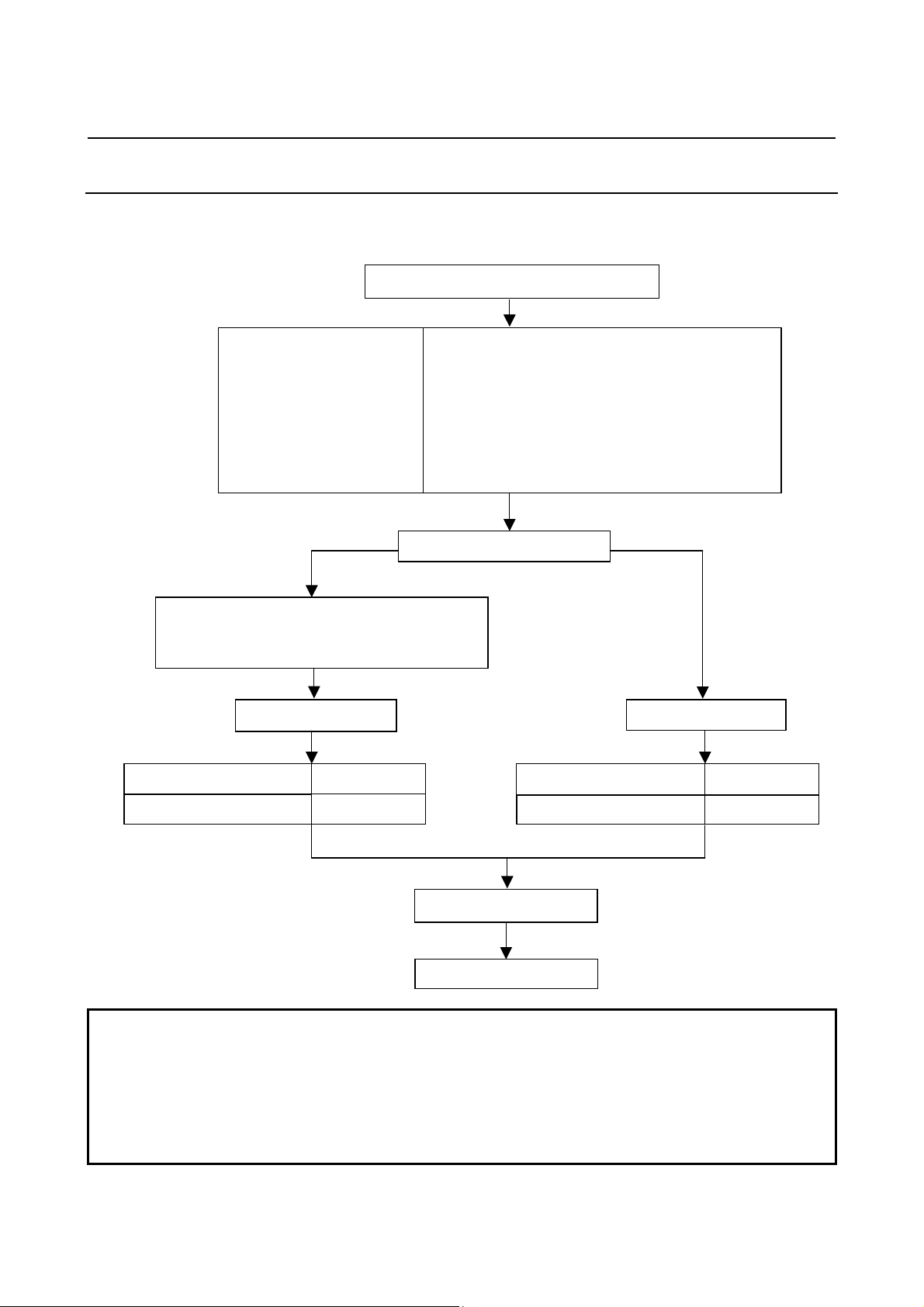
2.1.2 Parameter Initialization Flow
On the servo setting and servo adjustment screens, set the following:
In emergency stop state, switch on NC.
Initialization bits
Motor No.
MR
CMR
Move direction
Reference counter
Velocity gain
Make settings for using separate detector.
No. 1807#3 = 1, 1815#1 = 1 (Series 15i)
No. 1815#1 = 1 (Series 30i, Series 16i and so on)
Set flexible feed gear.
Number of velocity pulses
8192
00000000 See (2) and (8)-(b)-3 in Subsec. 2.1.3.
See (3) in Subsec. 2.1.3.
See (4) in Subsec. 2.1.3.
See (5) in Subsec. 2.1.3.
See (7) in Subsec. 2.1.3.
See (9) in Subsec. 2.1.3.
Set 150% if the machine inertia is unknown.
(Equivalent to load inertia ratio parameter)
Semi-closed loop Closed loop
Which system is being used?
← See (6) in Subsec. 2.1.3. →
Number of velocity pulses
Set flexible feed gear.
8192
Number of position pulses
Ns (Note 1
Number of position pulses
Turn power off then on.
End of parameter setting
12500
NOTE
1 When a separate detector of A/B phase parallel type and a serial linear scale are
used, Ns indicates the number of feedback pulses per motor revolution, sent from
the separate detector.
When a serial rotary scale is used, the number of pulses is calculated using
following expression: 12500 × (gear reduction ratio between the motor and table)
See (8)-(b)-2 in Subsec. 2.1.3.
- 9 -
Page 20
2. SETTING αiS/αiF/βiS SERIES SERVO PARAMETERS B-65270EN/05
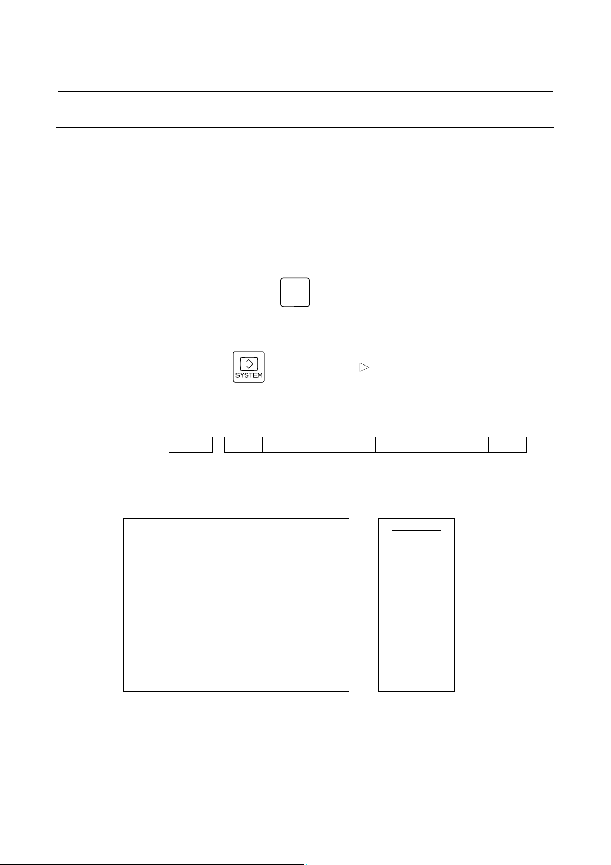
2.1.3 Servo Parameter Initialization Procedure
(1) Preparation
Switch on the NC in an emergency stop state.
Enable parameter writing (PWE = 1).
Initialize servo parameters on the servo setting screen.
For a Power Mate i with no CRT, specify a value for an item number
on the servo setting screen. See Fig. 2.1.3.
To display the servo setting screen, follow the procedure below, using
the key on the NC.
- Series 15i
Press the
SYSTEM
key several times, and the servo setting screen will
appear.
- Series30i,31i,32i,16i,18i,21i,20i,0i
→ [SYSTEM] → [ ] → [SV-PRM]
If no servo screen appears, set the following parameter as shown, and
switch the NC off and on again.
#7 #6 #5 #4 #3 #2 #1 #0
3111 SVS
SVS (#0) 1: Displays the servo screen.
When the following screen appears, move the cursor to the item you
want to specify, and enter the value directly.
Power Mate
No.2000
No.2020
No.2001
No.1820
No.2084
No.2085
No.2022
No.2023
No.2024
No.1821
X axis
16
2
1
100
111
8192
12500
10000
01000 N0000
Z axis
00001010
16
00000000
2
1
100
111
8192
12500
10000
Servo set
INITIAL SET BITS
Motor ID No.
AMR
CMR
Feed gear N
(N/M) M
Direction Set
Velocity Pulse No.
Position Pulse No.
Ref. counter
Fig. 2.1.3 Servo setting screen Correspondence of Power Mate i
00001010
00000000
- 10 -
Page 21

B-65270EN/05 2. SETTING αiS/αiF/βiS SERIES SERVO PARAMETERS
(2) Initialization
Start initialization.
Do not power off the NC until step (11).
#7 #6 #5 #4 #3 #2 #1 #0
INITIAL SET BIT PRMC DGPR PLC0
( Note)
Reset initialization bit 1 to 0.
DGPR(#1)=0
After initialization is completed, DGPR (#1) is set to 1.
NOTE
Once initialization has been completed, bit 3
(PRMC) for initialization automatically set to 1.
(Except Series 30i)
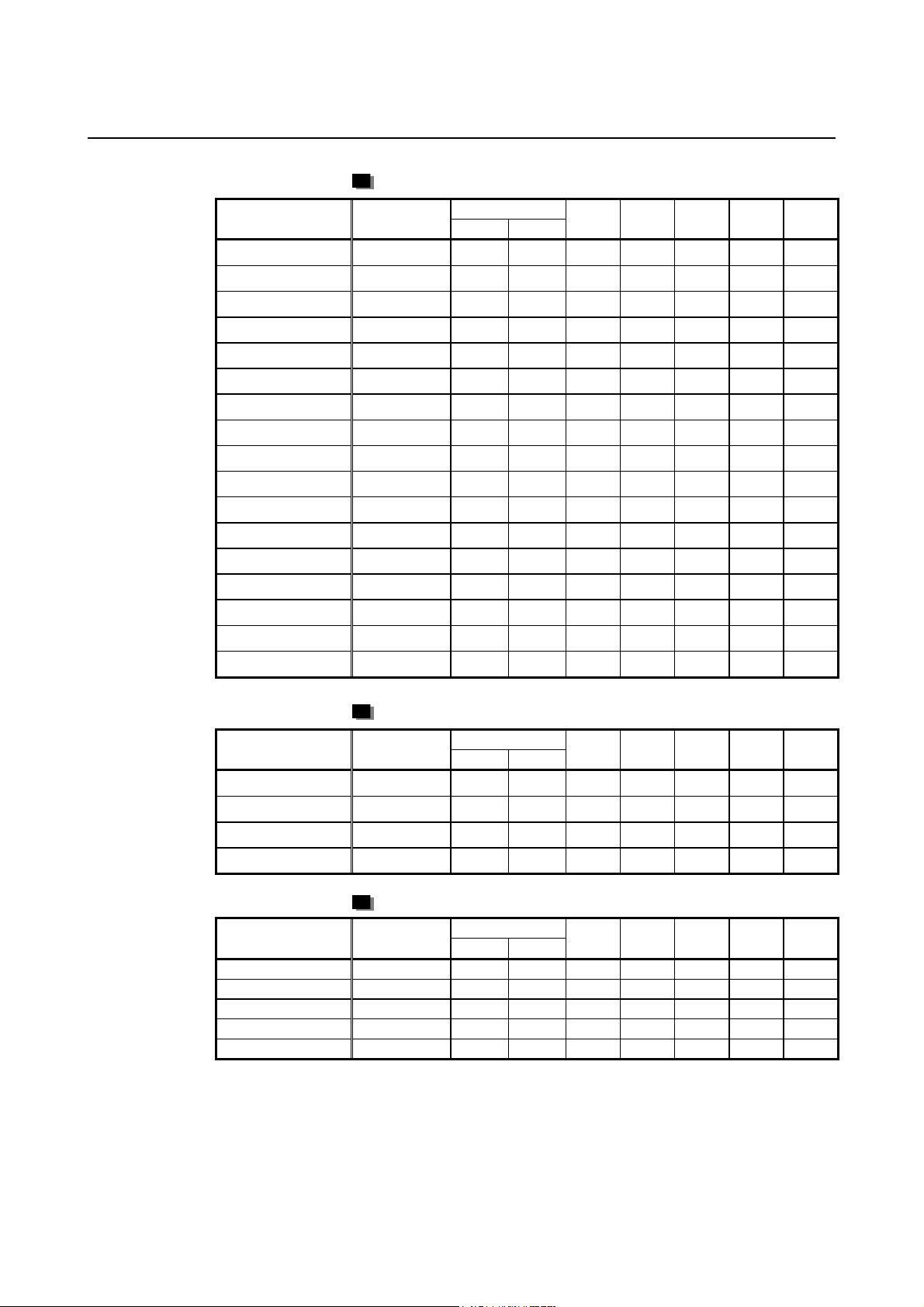
(3) Motor ID No. setting
Specify the motor ID number.
Select the motor ID number of a motor to be used according to the
motor model and motor specification (the middle four digits in
A06B-****
When using servo HRV3 or HRV4 control, perform loading by using
the motor ID number for servo HRV2 control. Loading is possible
with the series and editions listed in the table and later editions.
The mark "x" indicates a value that varies depending on the options
used.
The mark "-" indicates that automatic loading of standard parameters
is not supported as of February, 2005.
NOTE
• Series 30i
Specify the motor ID number for servo HRV2 control.
• Other than the Series 30i
When a pair of the values set in parameter No. 1023 (servo axis number) are
consecutive odd and even numbers, set motor ID numbers for servo HRV control of
the same type.
(Correct examples)
Servo axes when parameter No.1023= 1,2: Motor ID number for servo HRV2 control
Servo axes when parameter No.1023= 3,4: Motor ID number for servo HRV1 control
(Wrong examples)
Servo axes when parameter No.1023= 1: Motor ID number for servo HRV2 control
Servo axes when parameter No.1023= 2,3: Motor ID number for servo HRV1 control
-B***) listed in the following tables.
- 11 -
Page 22

2. SETTING αiS/αiF/βiS SERIES SERVO PARAMETERS B-65270EN/05
αiS series servo motor
Motor model
αiS2/
5000
αiS
2/6000
αiS4
/5000
αiS
8/4000
αiS
8/6000
αiS
12/4000
αiS
22/4000
αiS
30/4000
αiS
40/4000
αiS5
0/3000
αiS
50/3000 FAN
αiS
100/2500
αiS
200/2500
αiS
300/2000
αiS
500/2000
Motor
specification
0212 162 262 A H A A A
0218 - 284 G - B B -
0215 165 265 A H A A A
0235 185 285 A H A A A
0232 - 290 G - B B -
0238 188 288 A H A A A
0265 215 315 A H A A A
0268 218 318 A H A A A
0272 222 322 A H A A A
0274 224 324 B V A A F
0275-Bx1x 225 325 A N A A D
0285 235 335 A T A A F
0288 238 338 A T A A F
0292 - 342 B V A A -
0295 245 345 A T A A F
Motor ID No.
HRV1 HRV2
90D0
90E0
90B0
90B5
90B6
90B1 9096
Motor model
αiF1/5000
αiF2/5000
αiF4/4000
αiF8/3000
αiF12/3000
αiF22/3000
αiF30/3000
αiF40/3000
αiF40/3000
FAN
αiF series servo motor
Motor
specification
0202 152 252 A H A A A
0205 155 255 A H A A A
0223 173 273 A H A A A
0227 177 277 A H A A A
0243 193 293 A H A A A
0247 197 297 A H A A A
0253 203 303 A H A A A
0257 207 307 A H A A A
0258-Bx1x 208 308 A I A A C
Motor ID No.
HRV1 HRV2
90D0
90E0
90B0
90B5
90B6
90B1 9096
- 12 -
Page 23
B-65270EN/05 2. SETTING αiS/αiF/βiS SERIES SERVO PARAMETERS
αiS(HV) series servo motor
Motor model
αiS2/
5000HV
αiS
2/6000HV
αiS
4/5000HV
αiS
8/4000HV
αiS
8/6000HV
αiS
12/4000HV
αiS
22/4000HV
αiS
30/4000HV
αiS
40/4000HV
αiS
50/3000HV FAN
αiS
50/3000HV
αiS
100/2500HV
αiS
200/2500HV
αiS
300/2000HV
αiS
500/2000HV
αiS
1000/2000HV
αiS
2000/2000HV
Motor
specification
0213 163 263 A Q A A D
0219 - 287 G - B B -
0216 166 266 A Q A A D
0236 186 286 A N A A D
0233 - 292 G - B B -
0239 189 289 A N A A D
0266 216 316 A N A A D
0269 219 319 A N A A D
0273 223 323 A N A A D
0276-Bx1x 226 326 A N A A D
0277 227 327 B V A A F
0286 236 336 B V A A F
0289 239 339 B V A A F
0293 243 343 B V A A F
0296 246 346 B V A A F
0298 248 348 B V A A F
0091 - 340 - - - B -
Motor ID No.
HRV1 HRV2
90D0
90E0
90B0
90B5
90B6
90B1 9096
Motor model
αiF
4/4000HV
αiF
8/3000HV
αiF
12/3000HV
αiF
22/3000HV
Motor model
αC4/3000i
αC8/2000i
αC12/2000i
αC22/2000i
αC30/1500i
αiF(HV) series servo motor
Motor
specification
0225 175 275 A Q A A E
0229 179 279 A Q A A E
0245 195 295 A Q A A E
0249 199 299 A Q A A E
Motor ID No.
HRV1 HRV2
90D0
90E0
90B0
90B5
90B6
90B1 9096
αCi series servo motor
Motor
specification
0221 171 271 A H A A A
0226 176 276 A H A A A
0241 191 291 A H A A A
0246 196 296 A H A A A
0251 201 301 A H A A A
Motor ID No.
HRV1 HRV2
90D0
90E0
90B0
90B5
90B6
90B1 9096
- 13 -
Page 24

2. SETTING αiS/αiF/βiS SERIES SERVO PARAMETERS B-65270EN/05
A
A
βiS series servo motor
Motor model
βiS0.2/
5000
βiS0.3/
5000
βiS0.4/
5000
βiS0.5/
5000
βiS0.5/
6000
βiS1/
5000
βiS1/
6000
βiS2/
4000
βiS4/
4000
βiS8/
3000
βiS12/
3000
βiS22/
2000
Motor
specification
0111 4A - 260 A N A A
0112 4A - 261 A N A A
0114 20A - 280 A N A A
0115 20A 181 281 A N A A D
0115 20A 181 281 G - B B -
0116 20A 182 282 A N A A D
0116 20A 182 282 G - B B -
0061
0063
0075
0078 40A 172 272 B V A A F
0085 40A 174 274 B V A A F
mplifier
driving
20A 153 253 B V A A F
40A 154 254 B V A A F
20A 156 256 B V A A F
40A 157 257 B V A A F
20A 158 258 B V A A F
40A 159 259 B V A A F
Motor ID No.
HRV1 HRV2
90D0
90E0
90B0
90B5
90B6
90B1 9096
*
*
*
Motor model
βiS2/
4000HV
βiS4/4
000HV
βiS8/3000HV
βiS12/
3000HV
βiS22/
2000HV
With the βiS0.2/5000, βiS0.3/5000, and βiS0.4/5000, HRV1 control
cannot be used. Therefore, it cannot be used with Series 9096.
βiS(HV) series servo motor
Motor
specification
0062 10A 151 251 - - B - -
0064 10A 164 264 - - B - -
0076 10A 167 267 - - B - -
0079 20A 170 270 - - B - -
0086 20A 178 278 - - B - -
mplifier
driving
Motor ID No.
HRV1 HRV2
90D0
90E0
90B0
90B5
90B6
90B1 9096
The mark "-" indicates that automatic loading of standard parameters
is not supported as of February, 2005.
- 14 -
Page 25

B-65270EN/05 2. SETTING αiS/αiF/βiS SERIES SERVO PARAMETERS
Linear motor
Linear motor parameters for servo HRV2 control
Note: The following linear motors are driven by 200V.
Motor model
LiS300A1/4
LiS600A1/4
LiS900A1/4
LiS1500B1/4
LiS3000B2/2
LiS3000B2/4
LiS4500B2/2
LiS6000B2/2
LiS6000B2/4
LiS7500B2/2
LiS7500B2/4
LiS9000B2/2
LiS9000B2/4
LiS3300C1/2
LiS9000C2/2
LiS11000C2/2
LiS15000C2/2
LiS15000C2/3
LiS10000C3/2
LiS17000C3/2
Motor
specification
0441-B200 351 G - B B 0442-B200 353 G - B B 0443-B200 355 G - B B 0444-B210 357 G - B B 0445-B110 360 G - B B 0445-B210 362 G - B B 0446-B110 364 G - B B 0447-B110 368 G - B B 0447-B210 370 G - B B 0448-B110 372 G - B B 0448-B210 374 G B B 0449-B110 376 G - B B 0449-B210 378 G - B B
0451-B110 380 G - B B 0454-B110 384 G - B B 0455-B110 388 G - B B 0456-B110 392 G - B B 0456-B210 394 G - B B 0457-B110 396 G - B B 0459-B110 400 G - B B -
Motor ID No.
90D0
90E0
90B0
90B5
90B6
90B1 9096
Note: The following linear motors are driven by 400V.
Motor model
LiS1500B1/4
LiS3000B2/2
LiS4500B2/2HV
LiS4500B2/2
LiS6000B2/2HV
LiS6000B2/2
LiS7500B2/2HV
LiS7500B2/2
LiS9000B2/2
LiS3300C1/2
LiS9000C2/2
LiS11000C2/2HV
LiS11000C2/2
LiS15000C2/3HV
LiS10000C3/2
LiS17000C3/2
Motor
specification
0444-B210 358 G - B B 0445-B110 361 G - B B 0446-B010 363 G - B B 0446-B110 365 G - B B 0447-B010 367 G - B B 0447-B110 369 G - B B 0448-B010 371 G - B B 0448-B110 373 G - B B 0449-B110 377 G - B B 0451-B110 381 G - B B 0454-B110 385 G B B
0455-B010 387 G - B B 0455-B110 389 G - B B 0456-B010 391 G - B B 0457-B110 397 G - B B 0459-B110 401 G - B B -
Motor ID No.
90D0
90E0
90B0
90B5
90B6
90B1 9096
- 15 -
Page 26

2. SETTING αiS/αiF/βiS SERIES SERVO PARAMETERS B-65270EN/05
Linear motor parameters for servo HRV1 control
Motor model
LiS1500B1/4
LiS3000B2/2
LiS6000B2/2
LiS9000B2/2
LiS1500C2/2
LiS3000B2/4
LiS6000B2/4
LiS9000B2/4
LiS15000C2/3
LiS300A1/4
LiS600A1/4
LiS900A1/4
LiS6000B2/4
LiS9000B2/2
LiS9000B2/4
LiS15000C2/2
Motor
specification
0444-B210 90 A A A A A
0445-B110 91 A A A A A
0447-B110 92 A A A A A
0449-B110 93 A A A A A
0456-B110 94 A A A A A
0445-B210 120 A A A A A
0447-B210 121 A A A A A
0449-B210 122 A A A A A
0456-B210 123 A A A A A
0441-B200 124 A A A A A
0442-B200 125 A A A A A
0443-B200 126 A A A A A
0412-B811
0413
0413-B811
0414
Motor ID No.
127
(160-A driving)
128
(160-A driving)
129
(360-A driving)
130
(360-A driving)
90D0
90B0
90E0
A R A A D
A N A A D
A Q A A D
A Q A A D
90B5
90B6
90B1 9096
(Reference)
The parameter table presented in Chapter 6 has two motor ID Nos. for
the same linear motor. One of the two is for driving the α series servo
amplifiers (130A and 240A). Be careful not to use the wrong ID No.
αi servo amplifier driving
Amplifier
maximum
current [A]
Motor ID No.
Motor model
LiS6000B2/4
LiS9000B2/2
LiS9000B2/4
LiS15000C2/2
α servo amplifier driving
Amplifier
maximum
current [A]
240 121 160 127
130 93 160 128
240 122 360 129
240 94 360 130
Motor ID No.
(4) AMR setting
For AMR, set 00000000. When using a linear motor, set AMR
according to the description in Section 4.14, "LINEAR MOTOR
PARAMETER SETTING".
αiS/αiF/βiS motor
00000000
- 16 -
Page 27
B-65270EN/05 2. SETTING αiS/αiF/βiS SERIES SERVO PARAMETERS
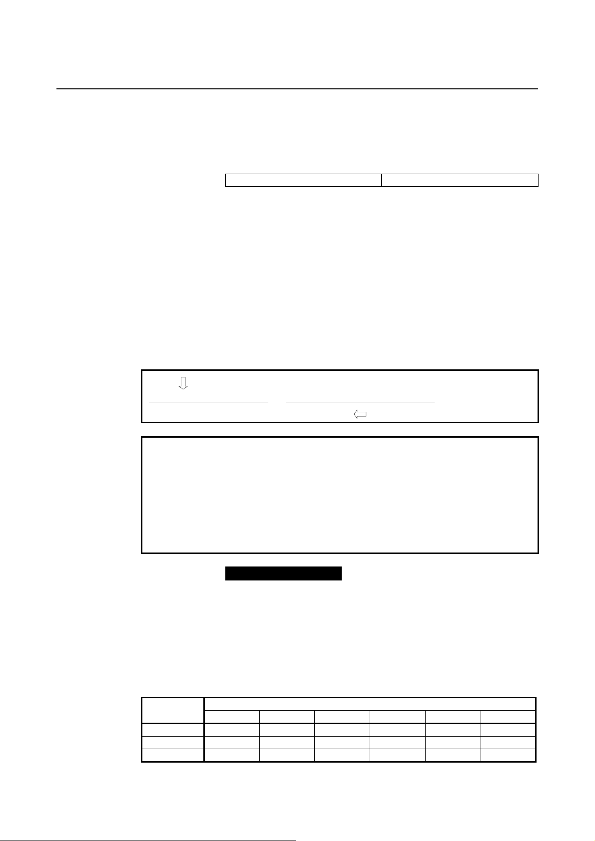
(5) CMR setting
Set CMR, Command Multiply Ratio, it converts the axis movement
command into pulses-
with the scale of a distance the NC instructs the machine to move.
CMR = Command unit / Detection unit
CMR 1/2 to 48 Setting value = CMR × 2
Usually, set CMR with 2, because command unit = detection unit
(CMR = 1).
(6) Flexible feed gear setting
Specify the flexible feed gear (F⋅FG). This function makes it easy to
specify a detection unit for the leads and gear reduction ratios of
various ball screws by changing the number of position feedback
pulses from the Pulsecoder or separate detector. It converts the
incoming number of pulses from the position detector so that it
matches the commanded number of pulses.
(a) Semi-closed feedback loop
Setting for the αi Pulsecoder
(Note 1) Necessary position feedback pulses
F⋅FG numerator (≤ 32767) per motor revolution
= (as irreducible fraction)
F⋅FG denominator (≤ 32767) 1,000,000 (Note 2)
NOTE
1 For both F⋅FG numerator and denominator, the maximum setting
value (after reduced) is 32767.
2 αi Pulsecoders assume one million pulses per motor revolution,
irrespective of resolution, for the flexible feed gear setting.
3 If the calculation of the number of pulses required per motor
revolution involves π, such as when a rack and pinion are used,
assume π to be approximately 355/113.
Example of setting
If the ball screw used in direct coupling has a lead of 5 mm/rev and
the detection unit is 1 µm
The number of pulses generated per motor turn (5 mm) is:
5/0.001 = 5000 (pulses)
Because the αi Pulsecoder feeds back 1000000 pulses per motor turn:
FFG = 5000 / 1000000 = 1 / 200
Other FFG (numerator/denominator) setting examples, where the gear
reduction ratio is assumed to be 1:1
Ball screw lead Detection
unit
1µm 6 / 1000 8 / 1000 10 / 1000 12 / 1000 16 / 1000 20 / 1000
0.5µm 12 / 1000 16 / 1000 20 / 1000 24 / 1000 32 / 1000 40 / 1000
0.1µm 60 / 1000 80 / 1000 100 / 1000 120 / 1000 160 / 1000 200 / 1000
6mm 8mm 10mm 12mm 16mm 20mm
- 17 -
Page 28

2. SETTING αiS/αiF/βiS SERIES SERVO PARAMETERS B-65270EN/05
r
N
Example of setting
If the gear reduction ratio between the rotation axis motor and table is
10:1 and the detection unit is 1/1000 degrees
The table rotates through 360/10 degrees when the motor makes one
turn.
The number of position pulses necessary for the motor to make one
turn is:
360/10 ÷ (1/1000) = 36000 pulses
F⋅FG numerato
36,000 36
= =
F⋅FG denominator 1,000,000 1,000
If the gear reduction ratio between the rotation axis motor and table is
300:1 and the detection unit is 1/10000 degrees
The table rotates through 360/300 degrees when the motor makes one
turn.
The number of position pulses necessary for the motor to make one
turn is:
360/300 ÷ (1/1000) = 12000 pulses
F⋅FG numerator 12,000 12
= =
F⋅FG denominator 1,000,000 1000
(b) Full-closed feedback loop
Setting for use of a separate detector (full-closed)
Number of position pulses corresponding
F⋅FG numerator (≤ 32767) to a predetermined amount of travel
= (as irreducible fraction)
F⋅FG denominator (≤ 32767) Number of position pulses corresponding
to a predetermined amount of travel from
a separate detector
Example of setting
To detect a distance of 1-µm using a 0.5-µm scale, set the following:
(L represents a constant distance.)
umerator of F⋅FG L/1 1
= =
Denominator of F⋅FG L/0.5 2
Other FFG (numerator/denominator) setting examples
Detection unit
1µm 1 / 1 1 / 2 1 / 10 1 / 20
0.5µm - 1 / 1 1 / 5 1 / 10
0.1µm - - 1 / 1 1 / 2
1 µm 0.5 µm 0.1 µm 0.05 µm
Scale resolution
- 18 -
Page 29
B-65270EN/05 2. SETTING αiS/αiF/βiS SERIES SERVO PARAMETERS
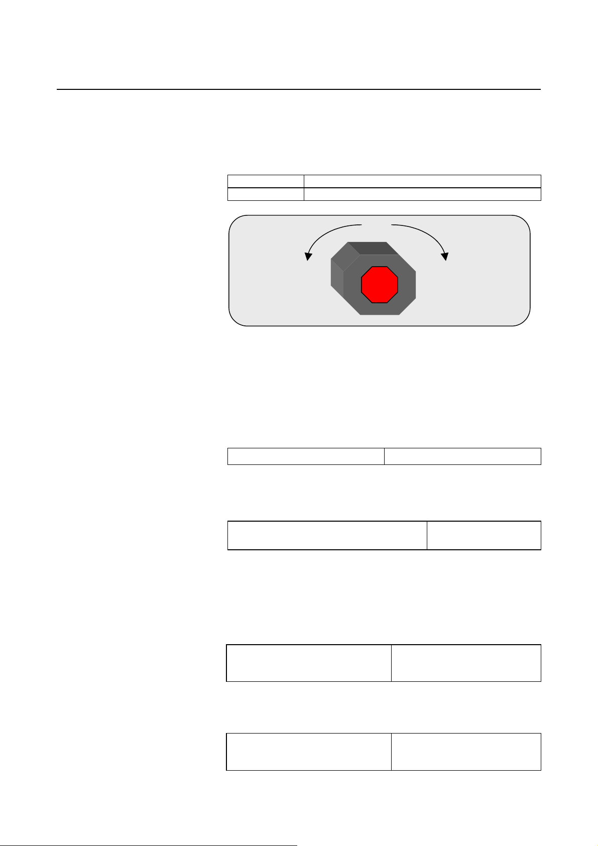
(7) Motor rotation direction setting
Set the direction in which the motor is to turn when a positive value is
specified as a move command. For linear motors, set the parameter
according to the description in Section 4.14, "LINEAR MOTOR
PARAMETER SETTING".
111 Clockwise as viewed from the Pulsecoder
−111 Counterclockwise as viewed from the Pulsecoder
Counterclockwise as
viewed from the
Pulsecoder
Set -111.
FANUC
Clockwise as viewed from
the Pulsecoder
Set 111.
(8) Specify the number of velocity pulses and the number of position pulses.
Set the number of velocity pulses and the number of position pulses
according to the connected detector. For linear motors, set these
parameters according to the description in Section 4.14, "LINEAR
MOTOR PARAMETER SETTING".
(a) Number of velocity pulses
Set the number of velocity pulses to 8192.
αiS/αiF/βiS motor
(b) Number of position pulses
(b)-1 Number of position pulses for semi-closed feedback loop
Set the number of position pulses to 12500.
Number of position pulses
(αiS/αiF/βiS motor, semi-closed feedback loop)
(b)-2 Number of position pulses for full-closed feedback loop
(See Subsections 2.1.4 and 2.1.5)
Set the number of position pulses to the number of pulses fed back
from the separate detector when the motor makes one turn. (The
flexible feed gear has nothing to do with the calculation of the number
of position pulses).
Number of position pulses (full-closed
feedback loop)
When using a serial rotary scale with a resolution of 1,000,000 pulses
per revolution, set a value assuming that 12500 is equivalent to
1,000,000 pulses.
Number of position pulses (full-closed
feedback loop)
* 1,000,000 pulses / rev
8192
12500
Number of pulses fed back from the
separate detector when the motor
makes one turn
12,500 ×
(motor-table gear reduction ratio)
- 19 -
Page 30

2. SETTING αiS/αiF/βiS SERIES SERVO PARAMETERS B-65270EN/05
Example 1:
Parallel type, serial linear scale
If the ball screw used in direct coupling has a lead of 10 mm and
the separate detector used has a resolution of 0.5 µm per pulse
Number of position pulses = 10 / 0.0005 = 20,000
Example 2:
Serial rotary scale
If the motor-table gear reduction ratio is 10:1,
Number of position pulses = 12,500 × (1/10) = 1250
(b)-3 If the setting for the number of position pulses is larger than 32767
Conventionally, initialization bit 0 (high resolution bit) must be
i series CNC,
2628 (FS15i)
2185 (FS30i,16i)
changed according to the command unit. For the current
however, there is no mutual dependence between the command unit
and initialization bit 0.
Of course, the conventional setting method is applicable, but using the
conversion coefficient for the number of position feedback pulses
makes the setting easier.
Conversion coefficient for the number of position feedback pulses
Series 90E0, Series 90D0, Series 90B0, Series 90B5, Series 90B6,
Series 90B1 :
Set the number of position pulses with a product of two
parameters, using the conversion coefficient for the number of
position feedback pulses.
Number of feedback pulses per motor revolution, sent from the
separate detector
= Number of position pulses × Conversion coefficient for the
number of position feedback pulses
Series 9096 :
No conversion coefficient for the number of position feedback
pulses can be used. As usual, set the initialization bit 0 to 1, and
set the number of velocity pulses and the number of position
pulses to 1/10 the respective values stated earlier.
Number of feedback pulses per motor revolution, sent from the
separate detector
= Number of position pulses × 10
→ See Supplementary 3 of Subsection 2.1.8.
- 20 -
Page 31

B-65270EN/05 2. SETTING αiS/αiF/βiS SERIES SERVO PARAMETERS
(9) Reference counter setting
Specify the reference counter.
The reference counter is used in making a return to the reference
position by a grid method.
(a) Semi-closed loop
Count on the reference
counter
NOTE
If the motor-table rotation ratio for a rotation axis is
not an integer, it is necessary to set the reference
counter capacity in such a way that points where
reference counter = 0 (grid points) appears always
at the same position for the table.
Example of setting
αi Pulsecoder and semi-closed loop (1-µm detection)
Ball screw lead
(mm/revolution)
10
20
30
When the number of position pulses corresponding to a single motor
revolution does not agree with the reference counter setting, the
position of the zero point depends on the start point.
In such a case, set the reference counter capacity with a fraction to
change the detection unit and eliminate the error in the reference
counter. (Except Series 9096)
Example of setting
System using a detection unit of 1 µm, a ball screw lead of 20
mm/revolution, and a gear reduction ratio of 1/17
(a)-1 Method of specifying the reference counter capacity with a fraction (except
Series 9096)
The number of position pulses necessary for the motor to make one
turn is: 20000/17
Set the following parameter as stated below.
1896 (FS15i)
1821 (FS30i, 16i)
[Valid data range] 0 to 99999999
Reference counter capacity (numerator)
Set the numerator of a fraction for the reference counter capacity.
Number of position pulses corresponding to a
=
single motor revolution or the same number
divided by an integer value
Necessary number of
position pulses
(pulse/revolution)
10000
20000
30000
Reference
counter
10000
20000
30000
Grid width
(mm)
10
20
30
- 21 -
Page 32

2. SETTING αiS/αiF/βiS SERIES SERVO PARAMETERS B-65270EN/05
2622 (FS15i)
2179 (FS30i, 16i)
Reference counter capacity (denominator)
[Valid data range] 0 to 32767
A value up to around 100 is assumed to be set as the denominator of
the reference counter capacity. Note that if a larger value is set, the
grid width becomes too small, which makes it difficult to perform
reference position return by grid method.
The denominator parameter is not indicated in the servo setting screen,
so it must be set in the parameter screen.
In this example, set the numerator and denominator, respectively, to
20000 and 17.
NOTE
The reference counter capacity takes only an
integer. If a fraction is specified for it, an interval
between points where reference counter = 0 is
corrected.
(It is impossible to control a position where the
number of pulses is smaller than one because of
the pulse control principle, grid interval correction is
performed in such a way that the grid point error
will always be less than one detection unit.)
(a)-2 Method of changing the detection unit
The number of position pulses necessary for the motor to make one
turn is: 20000/17
In this case, increase all the following parameter values by a factor of
17, and set the detection unit to 1/17 µm.
Parameter modification
FFG
CMR
Reference counter
Effective area
Position error limit in traveling
Position error limit in the stop state
Backlash
Changing the detection unit from 1 µm to 1/17 µm requires
multiplying each of the parameter settings made for the detection unit
by 17.
CAUTION
In addition to the above parameters, there are
some parameters that are to be set in detection
units. For details, see Appendix B.
Series 30i,15i,16i,0i,
PowerMatei, and other CNC
Servo screen
Servo screen
Servo screen
Nos. 1826, 1827
No. 1828
No. 1829
Nos. 1851, 1852
- 22 -
Page 33

B-65270EN/05 2. SETTING αiS/αiF/βiS SERIES SERVO PARAMETERS
Making these modifications eliminates the difference between the
number of position pulses corresponding to a single motor revolution
and the reference counter setting.
Number of position pulses corresponding to a single motor revolution
= 20000
Reference counter setting = 20000
(b) Full-closed loop (See Subsections 2.1.4 and 2.1.5)
Reference
counter setting
If the reference counter capacity setting is not an integer, see the
example in "Semi-closed loop."
Z-phase (reference-position) interval divided by the
=
detection unit, or this value sub-divided by an integer
value
NOTE
If the separate detector-table rotation ratio for the
rotation axis is not an integer, it is necessary to set
the reference counter capacity in such a way that
points where reference counter = 0 (grid points)
appear always at the same position for the table.
Example of setting
Example 1) When the Z-phase interval is 50 mm and the detection
unit is 1 µm:
Reference counter setting = 50,000/1 = 50,000
Example 2) When a rotation axis is used and the detection unit is
0.001°:
Reference counter setting = 360/0.001 = 360,000
Example 3) When a linear scale is used and a single Z phase exists:
Set the reference counter to 10000, 50000, or another
round number.
(10) Full-closed system setting (go to (11) if a semi-closed system is in use)
For a full-closed system, it is necessary to set the following function
bit.
(a) Series15i only
#7 #6 #5 #4 #3 #2 #1 #0
1807 (FS15i)
2002 (FS30i, 16i)
PFSE(#3) The separate position detector is:
PFSE
↑ To be specified only for the Series 15i
0: Not to be used
1: To be used
CAUTION
Specify this parameter only for the Series 15i.
- 23 -
Page 34

2. SETTING αiS/αiF/βiS SERIES SERVO PARAMETERS B-65270EN/05
(b) Series30i,15i,16i, 0i,Power Mate i, and so on
#7 #6 #5 #4 #3 #2 #1 #0
1815 OPTX
↑To be specified for
every NC.
OPTX(#1) The separate position detector is:
0: Not to be used
1: To be used
NOTE
For the Series 30i, 16i, 0i, Power Mate i, and other
NC, specifying this parameter automatically sets bit
3 of parameter No. 2002 to 1.
(11) NC restart
Switch the NC off and on again.
This completes servo parameter initialization.
If an invalid servo parameter setting alarm occurs, go to Subsec. 2.1.8.
If a servo alarm related to Pulsecoders occurs for an axis for which a
servo motor or amplifier is not connected, specify the following
parameter.
#7 #6 #5 #4 #3 #2 #1 #0
1953 (FS15i)
2009 (FS30i, 16i)
SERD
SERD (#0) The serial feedback dummy function is: (See Sec. 4.9 for function detail)
0 : Not used
1 : Used
(12) Absolute position detector setting
When you are going to use an αi/βi Pulsecoder as an absolute
Pulsecoder, use the following procedure.
Procedure
1. Specify the following parameter, then switch the NC off.
#7 #6 #5 #4 #3 #2 #1 #0
1815 APCx
APCx (#5) The absolute position detector is:
0: Not used
1: Used
2. After making sure that the battery for the Pulsecoder is connected,
3. A request to return to the reference position is
4. Cause the motor to make one turn by jogging.
5. Turn off and on the CNC.
6. A request to return to the reference position is
7. Do the reference position return.
turn off the CNC.
displayed.
displayed.
These steps
were added
for the α
Pulsecoder.
i/βi
- 24 -
Page 35

B-65270EN/05 2. SETTING αiS/αiF/βiS SERIES SERVO PARAMETERS
2.1.4 Setting Servo Parameters when a Separate Detector for the
Serial Interface is used
(1) Overview
When a separate detector of the serial output type is used, there is a
possibility that the detection unit becomes finer than the detection unit
currently used. Accordingly, a few modifications are made to the
setting method and values of servo parameters.
When using a separate detector of the serial output type, follow the
method explained below to set parameters.
(2) Series and editions of applicable servo software
(Series 30i,31i,32i)
Series 90D0/A(01) and subsequent editions
Series 90E0/A(01) and subsequent editions
(Series 15
Series 90B0/A(01) and subsequent editions
Series 90B1/A(01) and subsequent editions
Series 90B6/A(01) and subsequent editions
(Series 0
Series 90B5/A(01) and subsequent editions
(3) Classification of serial detectors and usable detector examples
Usable separate detectors for the serial interface are classified into
four major types as shown below. Note that parameter settings vary
with these types.
(a) Serial output type linear encoder
Minimum resolution Model Backup
MITSUTOYO Co., Ltd.
HEIDENHAIN
(b) Analog output type linear encoder plus high-resolution serial converter
manufactured by FANUC
Signal pitch Model Backup
MITUTOYO Co., Ltd.
HEIDENHAIN
Sony Precision Technology Inc.
(c) Serial output type rotary encoder
Minimum resolution
FANUC 220 pulse/rev αA1000S Required
i-B,16i-B,18i-B,21i-B,0i-B,0i Mate-B,Power Mate i)
i-C,0i Mate-C,20i-B)
0.05µm
0.05µm/0.1µm
0.05µm/0.1µm
20µm
20µm
20µm
(Note 1)
AT353, AT553 Not required
LC191F
LC491F
AT402 Required
LS486, LS186 Required
SH12 Required
Model Backup
Not required
Not required
- 25 -
Page 36

2. SETTING αiS/αiF/βiS SERIES SERVO PARAMETERS B-65270EN/05
(d) RCN220, RCN223, RCN723, and RCN727 manufactured by Heidenhain
Minimum resolution
HEIDENHAIN 220 pulse/rev
23
2
pulse/rev
27
2
pulse/rev
(Note 1)
Model Backup
RCN220
RCN223, 723
RCN727
Not required
Not required
Not required
NOTE
1 The minimum resolution of a rotary encoder is the resolution of the
encoder itself.
For the FANUC systems, however:
20
One million pulses/rev for a minimum resolution of 2
Eight million pulses/rev for a minimum resolution of 2
pulses/rev
23
pulses/rev
Eight million pulses/rev for a minimum resolution of 227 pulses/rev
(4) Setting parameters
Set the following parameters according to the type of the detector
(described in the previous item).
(a) Parameter setting for a linear encoder of a serial output type
(Parameter setting method)
In addition to the conventional settings for a separate detector (bit 1 of
parameter No. 1815 (Series30
i), bit 3 of parameter No. 1807 (Series 15i), and if needed, FSSB),
note the following parameters:
[Flexible feed gear]
Parameter Nos. 1977 and 1978 (Series 15i) or Nos. 2084 and 2085
(Series 30
i, 16i and so on)
Flexible feed gear (N/M)
= minimum resolution of detector [µm] / controller detection unit
[µm]
[Number of position pulses]
Parameter No. 1891 (Series 15i) or No. 2024 (Series 30i, 16i and so
on)
Number of position pulses
= Amount of movement per motor revolution [mm] /
detection unit of the sensor [mm]
* If the result of the above calculation does not fall in the setting
range (0 to 32767) for the number of position pulses, use
“position feedback pulse conversion coefficient” to specify the
number of position pulses according to the following procedure.
Number of position pulses to be set = A × B
Select B so that A is within 32767. Then, set the following:
A: Position pulses parameter (32767 or less)
No.1891 (Series15
B: Position pulses conversion coefficient parameter
No.2628 (Series15
i,15i,16i,18i,21i,20i, 0i, and Power Mate
i), No.2024 (Series 30i, 16i and so on)
i), No.2185 (Series 30i, 16i and so on)
- 26 -
Page 37

B-65270EN/05 2. SETTING αiS/αiF/βiS SERIES SERVO PARAMETERS
(Example of parameter setting)
[System configuration]
• The Series 16i is used.
• A linear scale with a minimum resolution of 0.1 µm is used.
• The least input increment of the controller is 1 µm.
• The amount of movement per motor revolution is 16 mm.
[Parameter setting]
• To enable a separate detector, set bit 1 of parameter No. 1815 to
1.
• Calculate the parameters for the flexible feed gear.
Because flexible feed gear (N/M) = 0.1 µm/1 µm = 1/10:
No. 2084 = 1 and No. 2085 = 10
• Calculate the number of position pulses.
Number of position pulses = 16 mm/0.0001mm = 160000
Because this result does not fall in the setting range (0 to 32767),
set A and B, respectively, with the "number of position pulses"
and "position pulses conversion coefficient" by assuming:
160,000 = 10,000 × 16 → A = 10,000 and B = 16
No.2024 = 10,000, No.2185 = 16
(b) Parameter setting for analog output type linear encoder +
FANUC high-resolution serial output circuit
(Parameter setting method)
In addition to the conventional separate detector settings (bit 1 of
parameter No. 1815 (Series15
Mate
FSSB setting), pay attention to the following parameter settings.
First check the type of the FANUC high-resolution output circuit to be
coupled to the linear encoder, and then determine the settings of the
following function bits.
[Function bit]
i, 30i,16i,18i,21i,20i, 0i, and Power
i), bit 3 of parameter No. 1807 (Series 15i), and, if necessary,
Circuit Specification
High-resolution serial output circuit A860-0333-T501 512
High-resolution serial output circuit H A860-0333-T701 2048
High-resolution serial output circuit C A860-0333-T801 2048
Interpolation
magnification
- 27 -
Page 38

2. SETTING αiS/αiF/βiS SERIES SERVO PARAMETERS B-65270EN/05
#7 #6 #5 #4 #3 #2 #1 #0
2687 (FS15i)
2274 (FS30i, 16i)
HP2048(#0) The 2048-magnification interpolation circuit (high-resolution serial
HP2048
output circuit H or C) is:
1: To be used
0: Not to be used
NOTE
This function bit can be used with the following
series and editions:
(Series 30i, 31i, 32i)
Series 90D0/A(01) and subsequent editions
Series 90E0/A(01) and subsequent editions
(Series 15i-B, 16i-B, 18i-B, 21i-B, 0i-B, 0i Mate-B,
Power Mate i)
Series 90B0/Q(17) and subsequent editions
Series 90B1/A(01) and subsequent editions
Series 90B6/A(01) and subsequent editions
(Series 0i-C, 0i Mate-C, 20i-B)
Series 90B5/A(01) and subsequent editions
If this bit is specified, the minimum resolution
setting of the detector is assumed to be:
Encoder signal pitch/512 [µm]
If the minimum resolution (signal pitch/2048 [µm])
is necessary as the detection unit, specify:
Flexible feed gear = 4/1
[Minimum resolution of the detector]
In the following calculation of a flexible feed gear and the number of
position pulses, the minimum detector resolution to be used is:
(Linear encoder signal pitch/512 [µm])
(Specifying the above function bit appropriately makes it unnecessary
to take the difference in the interpolation magnification among the
high-resolution serial output circuits into account. So always use 512
for calculations.)
[Flexible feed gear]
Parameters Nos. 1977 and 1978 (Series 15i) or Nos. 2084 and 2085
(Series 30
Flexible feed gear (N/M)
= minimum resolution of the detector [µm] /
detection unit of controller [µm]
i, 16i, and so on)
- 28 -
Page 39

B-65270EN/05 2. SETTING αiS/αiF/βiS SERIES SERVO PARAMETERS
[Number of position pulses]
Parameter No. 1891 (Series 15i) or No. 2024 (Series 30i, 16i, and so
on)
Number of position pulses
= Amount of movement per motor revolution [mm] /
minimum resolution of the detector [mm]
* If the result of the above calculation does not fall in the setting
range (0 to 32767) for the number of position pulses, use
“position feedback pulse conversion coefficient” to specify the
number of position pulses according to the following procedure.
Number of position pulses to be set = A × B
Select B so that A is within 32767. Then, set the following:
A: Position pulses parameter (32767 or less)
No.1891 (Series15
i), No.2024 (Series 30i, 16i, and so on)
B: Position pulses conversion coefficient parameter
No.2628 (Series15
i), No.2185 (Series 30i, 16i, and so on)
(Example of parameter setting)
[System configuration]
• The Series 16i is used.
• A linear encoder with a signal pitch of 20 µm is used.
• The linear encoder is coupled with high-resolution serial output
circuit H.
• The least input increment of the controller is 1 µm.
• The amount of movement per motor revolution is 16 mm.
[Parameter setting]
• To enable a separate detector, set bit 1 of parameter No. 1815 to
1.
• To use high-resolution serial output circuit H, set bit 0 of
parameter No. 2274 to 1.
Minimum resolution of the detector = 20 µm/512
= 0.0390625 µm
• Calculate the parameters for the flexible feed gear.
Because flexible feed gear (N/M)=(20/512µm)/1µm=5/128
No.2084=5, No.2085=128
• Calculate the number of position pulses.
Number of position pulses = 16 mm/(20/512µm) = 409,600
Because this result does not fall in the setting range (0 to 32767),
set A and B, respectively, with the "number of position pulses"
and "position pulses conversion coefficient" by assuming:
409,600 = 25,600 × 16 → A = 25,600, B = 16
No.2024 = 25,600, No.2185 = 16
- 29 -
Page 40

2. SETTING αiS/αiF/βiS SERIES SERVO PARAMETERS B-65270EN/05
(c) Parameter setting for the serial output type rotary encoder
* For explanations about the rotary encoders RCN220, RCN223,
RCN723, and RCN727 made by Heidenhain, see "Parameter
setting for the rotary encoders RCN220, RCN223, RCN723, and
RCN727 made by Heidenhain."
(Parameter setting method)
In addition to the conventional settings for a separate detector (bit 1 of
parameter No. 1815 (Series15
i), bit 3 of parameter No. 1807 (Series 15i), and if needed,
Mate
FSSB), note the following parameters:
[Flexible feed gear]
Parameters Nos. 1977 and 1978 (Series 15i) or Nos. 2084 and 2085
(Series 30
Flexible feed gear (N/M) =
(Amount of table movement [deg] per detector revolution) /
[Number of position pulses]
Parameter No. 1891 (Series 15
on)
Number of position pulses = 12500×(motor-to-table deceleration ratio)
* If the result of the above calculation does not fall in the setting
Number of position pulses to be set = A × B
Select B so that A is within 32767. Then, set the following:
i, 16i and so on)
(detection unit [deg]) / 1,000,000
range (0 to 32767) for the number of position pulses, use
“position feedback pulse conversion coefficient” to specify the
number of position pulses according to the following procedure.
A: Position pulses parameter (32767 or less)
No.1891 (Series15
B: Position pulses conversion coefficient parameter
No.2628 (Series15
i, 30i, 16i, 18i, 21i, 20i, 0i, and Power
i) or No. 2024 (Series 30i, 16i and so
i), No.2024 (Series 30i, 16i and so on)
i), No.2185 (Series 30i, 16i and so on)
(Example of parameter setting)
[System configuration]
• The Series 16i is used.
• The least input increment of the controller is 1/1000 degree.
• The amount of movement per motor revolution is 180 degrees
(deceleration ratio: 1/2)
• Table-to-separate-encoder reduction ratio = 1/1
- 30 -
Page 41

B-65270EN/05 2. SETTING αiS/αiF/βiS SERIES SERVO PARAMETERS
[Parameter setting]
• To enable a separate detector, set bit 1 of parameter No. 1815 to
1.
• Calculate the parameters for the flexible feed gear.
Because flexible feed gear (N/M)
=360 degrees /0.001 degrees /1,000,000 =36/100
No.2084=36, No.2085=100
• Calculate the number of position pulses.
Because number of position pulses = 12500 × (1/2)=6250
No.2024=6250
- 31 -
Page 42

2. SETTING αiS/αiF/βiS SERIES SERVO PARAMETERS B-65270EN/05
(d) Parameter setting for the rotary encoders RCN220, RCN223, RCN723, and
RCN727 made by Heidenhain
(Series and editions of applicable servo software)
To use high-resolution rotary encoder RCN220, RCN223, RCN723,
or RCN727 manufactured by Heidenhain, the following servo
software is required.
[RCN220,223,723]
(Series 30i,31i,32i)
Series 90D0/A(01) and subsequent editions
Series 90E0/A(01) and subsequent editions
(Series 15
i-B,16i-B,18i-B,21i-B,0i-B,0i Mate-B,Power Mate i)
Series 90B0/T(19) and subsequent editions
Series 90B1/A(01) and subsequent editions
Series 90B6/A(01) and subsequent editions
(Series 0
i-C,0i Mate-C,20i-B)
Series 90B5/A(01) and subsequent editions
[RCN727]
(Series 30i,31i,32i)
Series 90D0/J(10) and subsequent editions
Series 90E0/J(10) and subsequent editions
(Series 15
i-B,16i-B,18i-B,21i-B,0i-B,0i Mate-B,Power Mate i)
Series 90B1/B(02) and subsequent editions
(Parameter setting method)
To specify parameters for the high-resolution rotary encoders
RCN220, RCN223, RCN723, and RCN727 (supporting FANUC serial
interface) made by HEIDENHAIN, use the following procedure.
In addition to the conventional separate detector settings (bit 1 of
parameter No. 1815 (Series 30
i), bit 3 of parameter No. 1807 (Series 15i), and, if necessary, FSSB
setting), pay attention to the following parameter settings.
[Function bit]
To use the RCN220, RCN223, RCN723, or RCN727, set the
following function bit to 1.
#7 #6 #5 #4 #3 #2 #1 #0
2688 (FS15i)
2275 (FS30i, 16i)
RCNCLR 800PLS
800PLS (#0) A rotary encoder with eight million pulses per revolution is:
1: To be used. (To use the RCN223, RCN723, or RCN723, set the
bit to 1.)
0: Not to be used. (To use the RCN220, leave this bit set to 0.)
i, 15i, 16i, 18i, 21i, 0i, and Power Mate
- 32 -
Page 43

B-65270EN/05 2. SETTING αiS/αiF/βiS SERIES SERVO PARAMETERS
RCNCLR (#1) The number of revolution is:
1: To be cleared. (To use the RCN220, RCN223, RCN723, or
RCN727, set the bit to 1.)
0: Not to be cleared.
This function bit is to be set in combination with the number of data
mask digits, described below.
2807 (FS15i)
2394 (FS30i, 16i)
Number of data mask digits
[Settings] 8. (To use the RCN223, RCN723, or RCN727)
5. (To use the RCN220)
The value to be set in this parameter depends on the detector. At
present, only the above detectors require clearing the speed data.
This parameter is to be set in combination with RCNCLR, described
above.
NOTE
The speed data of the RCN220, RCN223,
RCN723, or RCN727 is maintained while the power
to the separate detector interface unit is on. The
data, however, is cleared when the unit is turned
off. Since the speed data becomes undetermined
depending on where the power is turned off, it is
necessary to make a setting to clear the speed
data. In addition, for this reason, the RCN220,
RCN223, RCN723, and RCN727 cannot be used
with a linear axis.
When using the RCN220, set the parameters for the flexible feed gear
and the number of position pulses according to the setting method
described in the previous item, "Parameter setting for the serial output
type rotary encoder".
The following explains how to calculate the parameter values when
the RCN223, RCN723, or RCN727 is used.
[Flexible feed gear]
Parameters Nos. 1977 and 1978 (Series 15i) or Nos. 2084 and 2085
(Series 30
Flexible feed gear (N/M) =
(Amount of table movement [deg] per detector revolution) /
For the RCN223, RCN723, and RCN727, the number of pulses per
detector turn is assumed to be eight million for calculation.
For the RCN727, when the detection unit is set to 1/8,000,000
revolution or less, the flexible feed gear may be set to up to 8/1. (If the
flexible feed gear is set to 8/1, the detection unit is 64,000,000 pulses
per revolution.)
i, 16i, and so on)
(detection unit [deg]) / 8,000,000
- 33 -
Page 44

2. SETTING αiS/αiF/βiS SERIES SERVO PARAMETERS B-65270EN/05
[Number of position pulses]
Parameter No. 1891 (Series 15
on)
Number of position pulses = 100,000×(motor-to-table reduction ratio)
* If the result of the above calculation does not fall in the setting
range (0 to 32767) for the number of position pulses, use
“position feedback pulse conversion coefficient” to specify the
number of position pulses according to the following procedure.
Number of position pulses to be set = A × B
Select B so that A is within 32767. Then, set the following:
A: Position pulses parameter (32767 or less)
No.1891 (Series15
B: Position pulses conversion coefficient parameter
No.2628 (Series15
[Reference counter capacity]
Parameter No. 1896 (Series 15i) or No. 1821 (Series 30i, 16i, and so
on)
Specify the number of feedback pulses per table turn (detection unit).
* If bit 0 of parameter No. 2688 (Series 15
(Series 30
table turn divided by 8 as the reference counter capacity. In this
case, eight grid points occur per table turn.
i, 16i, and so on) is 0, specify the number of pulses per
i) or No. 2024 (Series 30i, 16i, and so
i), No.2024 (Series 30i, 16i, and so on)
i), No.2185 (Series 30i, 16i, and so on)
i) or parameter No. 2275
(Example of parameter setting)
[System configuration]
• The Series 16i is used.
• The rotary encoder RCN223 made by HEIDENHAIN is used.
• The least input increment of the controller is 1/10,000 degree.
• The amount of movement per motor revolution is 180 degrees
(reduction ratio: 1/2)
• Table-to-separate-encoder reduction ratio = 1/1
[Parameter setting]
• To enable a separate detector, set bit 1 of parameter No. 1815 to
1.
• To use the detector RCN223, set bit 0 of parameter No. 2275 to 1,
bit 1 of this parameter to 1, and parameter No. 2394 to 8.
• Calculate the parameters for the flexible feed gear.
Because flexible feed gear (N/M) =
(360 degrees /0.0001 degrees)/8,000,000=9/20
No.2084=9, No.2085=20
• Calculate the number of position pulses.
Number of position pulses = 100,000 × (1/2) = 50,000
Because this result does not fall in the setting range (0 to 32767),
set A and B, respectively, with the "number of position pulses"
and "position pulses conversion coefficient" by assuming:
50,000 = 12,500 × 4 → A = 12,500, B = 4
No.2024 = 12,500, No.2185 = 4
- 34 -
Page 45

B-65270EN/05 2. SETTING αiS/αiF/βiS SERIES SERVO PARAMETERS
• Calculate the reference counter capacity.
Reference counter capacity = 360 degrees/0.0001 degrees =
3,600,000
(About speed limit)
When the RCN223, RCN723, or RCN727 is used as a separate
detector, the maximum permissible speed that can be controlled is 938
-1. (*)
min
(See Appendix E.)
(*) The above maximum speed does not include hardware
limitations. For the maximum permissible speed of the detector
itself, refer to the specifications of the detector.
Setting the signal direction of the separate detector
When a serial type separate detector is used with its signals connected
in reverse directions, the following parameter must be used:
#7 #6 #5 #4 #3 #2 #1 #0
1960 (FS15i)
2018 (FS30i, 16i)
RVRSE
RVRSE (#0) The signal direction of the separate detector is:
1: Reversed.
0: Not reversed.
(5) Reference position return when a serial type separate detector is used as
an absolute-position detector
When a serial type separate detector is used as an absolute-position
detector, the phase-Z position must be passed once before a reference
position return is performed. Then, turn the CNC off then back on to
allow reference position return.
(This description does not apply if a detector that does not require
battery backup is in use.)
When reference position return is performed, adjust the deceleration
dog so that the grid-shifted reference position is not too near the
deceleration dog.
Encoder position
Reference position data
of the detector = 0
Position data from
the encoder
Direction of reference
Start position of
reference position return
position return
Reference counter
Reference position not grid-shifted
Grid-shifted reference
position
Grid shift amount
- 35 -
Reference counter capacity
Deceleration dog
To be adjusted so that the grid-shifted reference
position is not too near the deceleration dog.
Machine position
Page 46

2. SETTING αiS/αiF/βiS SERIES SERVO PARAMETERS B-65270EN/05
Y
A
2.1.5 Setting Servo Parameters when an Analog Input Separate
Interface Unit is used
(1) Overview
An analog input separate interface unit (analog SDU) can be
connected directly to an encoder having an analog output signal of 1
Vp-p. This subsection explains parameter settings to be made when
this unit is connected to a separate detector. After performing the
initialization procedure (full-closed loop) described in Subsection
2.1.3, change the setting described below according to the signal pitch
of the detector.
Configuration where analog SDU is used
X 000.000
000.000
Z 000.000
FSSB
nalog SDU
(2) Series and editions of applicable servo software
(Series 30i,31i,32i)
Series 90D0/J(10) and subsequent editions
Series 90E0/J(10) and subsequent editions
(3) Setting parameters
After performing the initialization (full-closed loop) described in
Subsection 2.1.3, change the following setting according to the signal
pitch of the detector:
[Setting the flexible feed gear]
1977 (FS15i)
2084 (FS30i,16i)
1978 (FS15i)
2085 (FS30i,16i)
1891 (FS15i)
2024 (FS30i,16i)
Numerator of flexible feed gear
Denominator of flexible feed gear
Set the flexible feed gear according to the following equation.
(Equation for parameter calculation)
Flexible feed gear (N/M) =
Detector signal pitch [µm]/512
Detection unit of controller [µm]
[Setting the number of position pulses]
Number of position pulses (PPLS)
Set the number of position pulses according to the following equation:
(Equation for parameter calculation)
Number of position pulses =
Amount of movement per motor revolution [mm]
If the calculation result is greater than 32767, use the following
position pulse conversion coefficient (PSMPYL) to obtain the
parameter setting (PPLS).
Detector signal pitch [mm]/512
Separate detector
1Vp-p
- 36 -
Page 47

B-65270EN/05 2. SETTING αiS/αiF/βiS SERIES SERVO PARAMETERS
2628 (FS15i)
2185 (FS30i,16ii)
Position pulse conversion coefficient (PSMPYL)
This parameter is used when the calculation result of the number of
position pulses is greater than 32767.
(Equation for parameter calculation)
Set this parameter so that the following equation is satisfied:
Number of position pulses = PPLS × PSMPYL
(→ See Supplementary 3 in Subsection 2.1.8.)
(Example of parameter setting)
[System configuration]
• The Series 30i is used.
• A linear scale with a signal pitch of 20 µm is used.
• The least input increment of the controller is 1 µm.
• The amount of movement per motor revolution is 16 mm.
[Parameter setting]
• To enable a separate detector, set bit 1 of parameter No. 1815 to
• Calculate the parameters for the flexible feed gear.
Because flexible feed gear (N/M)=(20/512µm)/1µm=5/128
No.2084=5, No.2085=128
• Calculate the number of position pulses.
Number of position pulses = 16 mm/(0.02 mm/512= 409,600
Because this result does not fall in the setting range (0 to 32767),
409,600 = 25,600 × 16 → A = 25,600, B = 16
No.2024 = 25,600, No.2185 = 16
1.
set A and B, respectively, with the "number of position pulses"
and "position pulses conversion coefficient" by assuming:
- 37 -
Page 48

2. SETTING αiS/αiF/βiS SERIES SERVO PARAMETERS B-65270EN/05
2.1.6 Setting Parameters When a CZi Sensor is used
(1) Overview
CZi sensors may be used in the following two ways:
<1> Used as a detector for a synchronous built-in servo motor
<2> Used as a separate detector
This subsection explains parameter settings to be made when the
sensor is used in each of these two ways.
The following two types of CZi sensor are available:
Signal interval Number of pulses at setting
CZi512S
CZi1024S
(2) Series and editions of applicable servo software
(Series 30i,31i,32i)
Series 90D0/A(01) and subsequent editions
Series 90E0/A(01) and subsequent editions
(Series 15i-B,16i-B,18i-B,21i-B,0i-B,0i Mate-B,Power Mate i)
Series 90B0/A(01) and subsequent editions
Series 90B1/A(01) and subsequent editions
Series 90B6/A(01) and subsequent editions
(Series 0i-C,0i Mate-C,20i-B)
Series 90B5/A(01) and subsequent editions
(*) With Series 90B0, 90B5, and 90B6, a CZi sensor cannot be used
as the detector for a synchronous built-in servo motor. (The CZi
sensor can be used as a separate detector.)
(3) Setting parameters (<1> Used as the detector for a synchronous built-in
servo motor)
[Setting AMR]
#7 #6 #5 #4 #3 #2 #1 #0
1806 (FS15i)
2001 (FS30i,16i)
0 AMR6 AMR5 AMR4 AMR3 AMR2 AMR1 AMR0
Set the value listed below according to the detector.
Detector AMR
CZi512S
CZi1024S
Setting example:
When an 88-pole synchronous built-in servo motor and the
CZi1024S are used:
Number of poles/2 = 88/2 = 44
→ The binary representation of the above value is 00101100.
This value is set in AMR.
512λ/rev 500,000pulse/rev
1024λ/rev 1,000,000pulse/rev
(*)
(*)
(*)
Set the number of poles of the synchronous built-in servo
motor in binary.
Set a value obtained by dividing the number of poles of the
synchronous built-in servo motor by 2 in binary.
- 38 -
Page 49

B-65270EN/05 2. SETTING αiS/αiF/βiS SERIES SERVO PARAMETERS
[Setting flexible feed gear]
1977 (FS15i)
2084 (FS30i,16i)
Flexible feed gear (numerator)
1978 (FS15i)
2085 (FS30i,16i)
Flexible feed gear (denominator)
Set the flexible feed gear according to the equation below.
The number of pulses per detector rotation is as follows:
Detector Number of pulses per detector rotation
Amount of movement per motor revolution [deg]/
CZi512S
Amount of movement per motor revolution [deg]/
CZi1024S
detection unit [deg]
500,000
detection unit [deg]
1,000,000
(Equation for parameter calculation)
Amount of movement per motor revolution [deg]/
Flexible feed gear (N/M) =
Number of pulses per detector rotation
detection unit [deg]
[Setting number of velocity pulses]
1876 (FS15i)
2023 (FS30i,16i)
Number of velocity pulses (PULCO)
Set a value listed in the following table according to the detector used.
Detector Number of velocity pulses
CZi512S
CZi1024S
4096
8192
[Setting number of position pulses]
1891 (FS15i)
2024 (FS30i,16i)
Number of position pulses (PPLS)
Set a value listed in the following table according to the detector used.
Detector Number of position pulses
CZi512S
CZi1024S
6250
12500
[Setting reference counter capacity]
1896 (FS15i)
1821 (FS30i,16i)
Reference counter capacity
Set the number of pulses per motor revolution (detection unit) or a
fraction of the integer value indicating the number of pulses per motor
revolution.
(Example of parameter setting)
[System configuration]
• The Series 30i is used.
• An 88-pole/rev, synchronous built-in servo motor is used.
• The detector used is the CZi512S.
• The least input increment of the controller is 1/1000 deg.
• Gear ratio 1:1
- 39 -
Page 50

2. SETTING αiS/αiF/βiS SERIES SERVO PARAMETERS B-65270EN/05
[Parameter setting]
AMR=01011000 (88 in decimal representation)
Flexible feed gear (N/M) = 360,000/500,000 = 18/25, so parameter No.
2084 = 18, and parameter No. 2085 = 25
Number of velocity pulses = 4096
Number of position pulses = 6235
Reference counter capacity = 60,000
(4) Setting parameters (Used as a separate detector)
After performing the initialization procedure (full-closed loop)
described in Subsection 2.1.3, change the settings described below
according to the signal pitch of the detector.
[Setting flexible feed gear]
1977 (FS15i)
2084 (FS30i,16i)
1978 (FS15i)
2085 (FS30i,16i)
1891 (FS15i)
2024 (FS30i,16i)
2628 (FS15i)
2185 (FS30i,16i)
Flexible feed gear (numerator) (N)
Flexible feed gear (denominator) (M)
Set a value listed in the following table according to the detector used.
Detector Flexible feed gear (N/M)
Amount of movement per motor revolution [deg]/
CZi512S
Amount of movement per motor revolution [deg]/
CZi1024S
detection unit [deg]
500,000
detection unit [deg]
1,000,000
[Setting number of position pulses]
Number of position pulses (PPLS)
Set a value listed in the following table according to the detector used.
Detector Number of position pulses
CZi512S
CZi1024S
6250 × (gear reduction ratio from the motor to table)
12500 × (gear reduction ratio from the motor to table)
If the calculation result is greater than 32767, use the following
position pulse conversion coefficient (PSMPYL) to obtain the
parameter value (PPLS).
Conversion coefficient for the number of position feedback pulses (PSMPYL)
This parameter is used when the calculated number of position pulses
is greater than 32767.
(Equation for parameter calculation)
Set this parameter so that the following equation is satisfied:
Number of position pulses = PPLS × PSMPYL
(→ See Supplementary 3 in Subsection 2.1.8.)
- 40 -
Page 51

B-65270EN/05 2. SETTING αiS/αiF/βiS SERIES SERVO PARAMETERS
[Setting reference counter capacity]
1896 (FS15i)
1821 (FS30i,16i)
Reference counter capacity
Set the number of pulses per detector (detection unit) or a fraction of
the integer value indicating the number of pulses per detector.
(Example of parameter setting)
[System configuration]
• The Series 30i is used.
• The detector used is the CZi1024S
• The least input increment of the controller is 1/1000 deg.
• Gear ratio 1:1
[Parameter setting]
Flexible feed gear (N/M) = 360,000/1,000,000=9/25,
so parameter No. 2084 = 9, and parameter No. 2085 = 25
Number of position pulses = 12500
Reference counter capacity = 360,000
- 41 -
Page 52
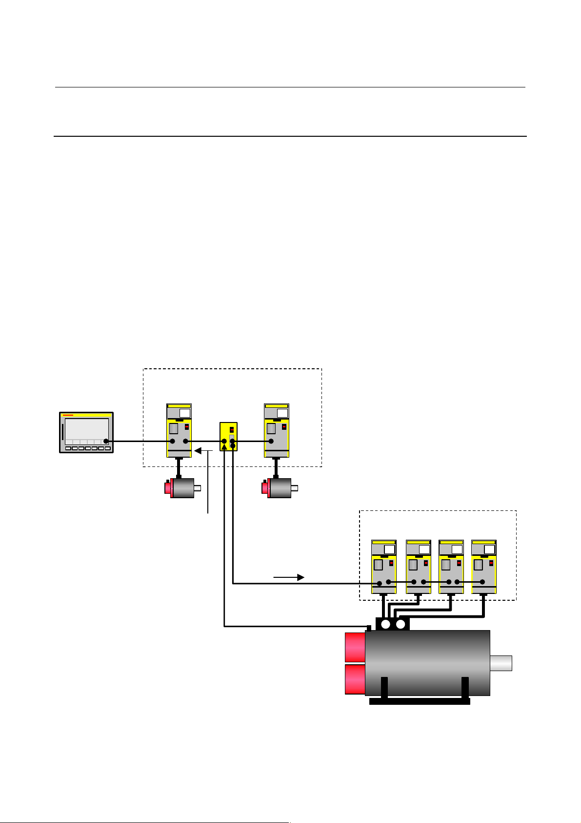
2. SETTING αiS/αiF/βiS SERIES SERVO PARAMETERS B-65270EN/05
A
A
A
A
A
A
A
α
2.1.7 Setting Parameters when the PWM Distribution Module is
used
(1) Overview
The PWM distribution module (PDM) distributes a copy of a PWM
command for one axis received from the CNC to more than one servo
amplifier. When receiving current feedback signals from the servo
amplifiers, the PDM obtains an average current value per servo
amplifier and transfers it to the CNC. Since the CNC regards servo
amplifiers connected to the PDM as one axis, use of the PDM allows
large output by parallel driving without increasing the number of axes
controlled by the CNC.
The PDM is used mainly for driving a servo motor having four or
Connection example:
Three slaves are recognized by the CNC.
MP
(X axis)
CNC
X 000.000
Y 000.000
Z 000.000
Main
FSSB
Current values fed back by
slaves are averaged and
fed back to the Y-axis by
the PDM.
more windings (such as the α
iS3000/2000HV).
α
PDM
(Y axis)
Local
FSSB
Y-axis is distributed to
multiple slaves.
MP
(Z axis)
PWM command for the
MP
Slave 1
MP
Slave 2
iS2000/2000HV and
MP
Slave 3
MP
Slave 4
Pulsecoder Feed back
Power
line
Servo motor (
2000/2000Hvis and so on)
- 42 -
Page 53

B-65270EN/05 2. SETTING αiS/αiF/βiS SERIES SERVO PARAMETERS
(2) Series and editions of applicable servo software
(Series 16i-B,18i-B,21i-B, Power Mate i)
Series 90B1/A(01) and subsequent editions
(*) When the PDM is used, it must be supported by the CNC system
software. (With the system software series listed below, the PDM
can be used.)
CNC model Series and edition
16i-MB
18i-MB
18i-MB5
21i-MB
Power Mate i-D
Power Mate i-H
B0HA-17 and subsequent editions
BDHA-17 and subsequent editions
BDHE-07 and subsequent editions
DDHA-17 and subsequent editions
88E1-01 and subsequent editions
88F2-01 and subsequent editions
(3) Setting parameters
(a) Setting for the PDM
When the PDM is used for an axis, servo HRV3 control must be set
for the axis. Set the parameter shown below.
After setting parameters with servo HRV2 control specified, set servo
HRV3 control by parameter setting as follows (
axis)
#7 #6 #5 #4 #3 #2 #1 #0
2013 (FS16i)
HRV3
HRV3(#0) 1: Uses servo HRV3 control.
0: Does not use servo HRV3 control.
(*) To use the PDM, set
HRV3 to 1. In actual control, operation
equivalent to HRV2 takes place. (It is also impossible to perform
switching between high-speed current control modes by G5.4.)
HRV3 = 1). (For each
For the axis for which the PDM is used, set the following parameter in
addition to the above HRV3 setting.
2165 (FS16i)
Set 0.
If this setting is omitted, the invalid motor-amplifier combination state
may occur.
(b) Setting for 16-pole servo motors
For an axis for which one of the following servo motor is used, set the
following parameter for 16-pole servo motors:
Servo motor name Motor specification
αiS2000/2000HV
αiS3000/2000HV
#7 #6 #5 #4 #3 #2 #1 #0
2220 (FS16i)
P16(#5) 1: Uses a 16-pole servo motor.
0: Does not use a 16-pole servo motor.
P16
0091
0092
- 43 -
Page 54

2. SETTING αiS/αiF/βiS SERIES SERVO PARAMETERS B-65270EN/05
#7 #6 #5 #4 #3 #2 #1 #0
2001 (FS16i)
AMR0 to 6 (#0 to 6) Set the AMR value according to the number of motor poles.
0 AMR6 AMR5 AMR4 AMR3 AMR2 AMR1 AMR0
AMR
6 543210
0 001000
0 000000Other than 16-pole servo motor (8-pole servo motor)
16-pole servo motor
iS2000/2000HV, αiS3000/2000HV
α
Number of motor poles
- 44 -
Page 55

B-65270EN/05 2. SETTING αiS/αiF/βiS SERIES SERVO PARAMETERS
2.1.8 Actions for Illegal Servo Parameter Setting Alarms
(1) Overview
When a setting value is beyond an allowable range, or when an
overflow occurs during internal calculation, an invalid parameter
setting alarm is issued.
This section explains the procedure to output information to identify
the location and the cause of an invalid parameter setting alarm.
(2) Series and editions of applicable servo software
(Series 30i,31i,32i)
Series90D0/A(01) and subsequent editions
Series90E0/A(01) and subsequent editions
(Series 15
Series9096/A(01) and subsequent editions
Series90B0/A(01) and subsequent editions
Series90B1/A(01) and subsequent editions
Series90B6/A(01) and subsequent editions
(Series 0
Series90B5/A(01) and subsequent editions
(3) Illegal parameter setting alarms that can be displayed in parameter error
detail display
Invalid parameter setting alarms detected by the servo software can be
displayed. Alarms detected by the system software cannot be
displayed here.
To check whether the servo software detects an alarm, check the
following:
Alarm 4 on the servo screen PRM
#7 #6 #5 #4 #3 #2 #1 #0
1: Alarm detected by the servo software (Detail display is enabled.)
0: Alarm detected by the system software (Detail display is not
The table given below lists the valid motor numbers for each series.
If a number beyond the indicated range is set, an illegal parameter
setting alarm is issued.
(In this case, keep PRM = 0.)
Series 9096/A(01) and subsequent editions 1 to 250
Series 90B0/H(08) and subsequent editions 1 to 350
Series 90B1/B(02) and subsequent editions 1 to 550
Series 90B5,90B6/B(02) and subsequent editions 1 to 550
Series 90D0,90E0/B(02) and subsequent editions 1 to 550
i-B,16i-B,18i-B,21i-B,0i-B,0i Mate-B,Power Mate i)
i-C,0i Mate-C,20i-B)
enabled.)
Servo software series/edition Motor No.
- 45 -
Page 56

2. SETTING αiS/αiF/βiS SERIES SERVO PARAMETERS B-65270EN/05
(4) Method
When an illegal parameter setting alarm detected by the servo
software is issued, analyze the cause of the alarm by following the
procedure explained below.
* When more than one alarm is issued, one of the causes of these
alarms is displayed. Analyze the alarms one by one.
Procedure for displaying detail information about an illegal parameter setting alarm
(For the Series 15
On the servo alarm screen, an item indicating parameter error
details is located in the lower left side. Check the number
indicated here.
(For the Series 30
On the diagnosis screen, search for No. 352. Check the number
written in No. 352.
Analyzing illegal parameter setting alarms in detail
i)
i, 16i and so on)
The detail alarm data basically consists of three to five digits as
shown:
0 0434
Location where an
alarm was caused
Cause of the alarm
Upper four digits:
Indicate the location where an alarm was caused.
Table 2.1.8 lists the displayed numbers and corresponding
parameter numbers.
*1 Basically, the low-order three digits of the 4-digit
parameter number of the Series 16
i indicate the
location where an alarm was caused. (When an alarm
is due to more than one parameter, these digits and
parameter numbers do not sometimes match.)
*2 When the digits are displayed on the servo alarm
screen (Series 15
i) or diagnosis screen (Series 30i, 16i,
and so on), 0s in high-order digits are not displayed.
Lowest digit:
Indicates the cause of an alarm.
The displayed numbers and their meanings are explained
below:
2: The set parameter is invalid. The corresponding
function does not operate.
3: The parameter value is beyond the setting range.
Alternatively, the parameter is not set.
4 to 9: An overflow occurred during internal calculation.
- 46 -
Page 57

B-65270EN/05 2. SETTING αiS/αiF/βiS SERIES SERVO PARAMETERS
Table 2.1.8 Detail analysis of illegal parameter setting alarms
Alarm
detail No.
83 - 2008
143 1708 2014
233 1876 2023
243 1891 2024
434
435
443
444
445
474
475
534
535
544
545
686
687
688
694
695
696
699
754
755
764
765
843 1977 2084
Parameter No.
(Series 15i)
1855 2043
1856 2044
1859 2047
1865 2053
1866 2054
1961 2068
1962 2069
1968 2075
1969 2076
Parameter No.
(Series 30i, 16i,
and so on)
Cause Action
Parameter settings related to
learning control are illegal
→ See Supplementary 1.
Parameter settings related to the HC
level of an αi amplifier are illegal.
Series 15i :
1707#1-#4 > 1708#1-#4
Series 16i and so on :
2013#1-#4 > 2014#1-#4
When initialization bit 0 is set to 1,
the number of velocity pulses
exceeds 13100.
When initialization bit 0 is set to 1,
the number of position pulses
exceeds 13100.
The internal value of the velocity
loop integral gain overflowed.
The internal value of the velocity
loop proportional gain overflowed.
The internal value of the observer
parameter (POA1) overflowed.
The internal value of a parameter
related to dead zone compensation
overflowed.
The internal value of a parameter
related to dead zone compensation
overflowed.
The internal value of the
feed-forward coefficient overflowed.
The internal value of the velocity
feed-forward coefficient overflowed.
The setting for this parameter has
overflowed.
The setting for this parameter has
overflowed.
A positive value is not set as the
flexible feed gear numerator.
Alternatively, the numerator of the
feed gear is greater than the
denominator.
Change the parameter settings so
that they fall in the applicable
range.
Make the following settings.
Series 15i :
1707#1-#4 ≤ 1708#1-#4
Series 30i, 16i, and so on :
2013#1-#4 ≤ 2014#1-#4
Correct the number of velocity
pulses so that it is within 13100.
Correct the number of position
pulses so that it is within 13100.
→ See Supplementary 3.
Decrease the value of the velocity
loop integral gain parameter.
Use the function for changing the
internal format of the velocity loop
proportional gain.
Alternatively, decrease the
parameter setting.
→ See Supplementary 4.
Correct the setting to
(−1) × (desired value)/10.
Decrease the setting to the extent
that the illegal parameter setting
alarm is not caused.
Decrease the setting to the extent
that the illegal parameter setting
alarm is not caused.
Use the position gain expansion
function.
→ See Supplementary 5.
Decrease the velocity feed-forward
coefficient.
This parameter is not used at
present. Set 0.
This parameter is not used at
present. Set 0.
Set a positive value as the flexible
feed gear numerator.
Alternatively, correct the parameter
so that the numerator of the feed
gear is less than or equal to the
denominator. (For other than
parallel type separate detectors)
- 47 -
Page 58

2. SETTING αiS/αiF/βiS SERIES SERVO PARAMETERS B-65270EN/05
Alarm
detail No.
853 1978 2085
883 1981 2088
884
885
886
926
927
928
953
994
995
996
1033 1996 2103
1123 1705 2112
1182
1284
1285
1294
1295
Parameter No.
(Series 15i)
1981 2088
1985 2092
1988
1763
2808
1992 2099
1729
1971
1972
1736 2128
1752 2129
Parameter No.
(Series 30i, 16i,
and so on)
2095
2140
2395
2118
2078
2079
Cause Action
A positive value is not set as the
flexible feed gear denominator.
For an axis with a serial type
separate detector, a value
exceeding 100 is set as the machine
velocity feedback coefficient.
The internal value of the machine
velocity feedback coefficient
overflowed.
The internal value of the look-ahead
feed-forward coefficient overflowed.
The internally set value of the
feed-forward timing adjustment
coefficient is ±12800 or over.
The internal value for N pulse
suppression overflowed.
There is a difference in retract
distance under unexpected
disturbance torque between position
tandem synchronous axes (if the
same-axis retract function is in use).
Although a linear motor is used, the
AMR conversion coefficient
parameter is not input.
The dual position feedback
conversion coefficient has not been
specified.
When a small value is set as the
number of velocity pulses, the
internal value of a parameter related
to current control overflows.
When a large value is set as the
number of velocity pulses, the
internal value of a parameter related
to current control overflows.
Set a positive value as the flexible
feed gear denominator.
For an axis with a serial type
separate detector, the upper limit
of the machine velocity feedback
coefficient is 100. Correct the
coefficient so that it does not
exceed 100.
Decrease the machine velocity
feedback coefficient.
Alternatively, use the
vibration-damping control function
that has an equivalent effect.
Use the "position gain precision
optimization function" or the
"position gain increment function".
→ See Supplementary 5.
This error can be avoided by
setting bit 4 of parameter No. 2612
(for the Series 15i) or bit 5 of
parameter No. 2224 (for the Series
16i and so on) to 1 if not
nano-interpolation is used.
Disable the N pulse suppression
function.
(Series 15i : No.1808#4=0, Series
30i, 16i, and so on : No.2003#4=0)
Alternatively, decrease the
parameter setting so that no
overflow will occur.
Set the same value for position
tandem synchronous axes.
Set the AMR conversion
coefficient.
Specify the dual position feedback
conversion coefficient.
Decrease the value in this
parameter to the extent that the
alarm is not caused.
When the value set in this
parameter is resolved to the form a
× 256 + b, set a smaller value in a
again.
- 48 -
Page 59

B-65270EN/05 2. SETTING αiS/αiF/βiS SERIES SERVO PARAMETERS
Alarm
detail No.
1393 1762 2139
1446
1447
1448
1454
1455
1456
1459
1493 1772 2149
1503 1773 2150
1793 2622 2179
1853 2628 2185
2243 2612#5 2224#5
2713 1707#0 2013#0
3423 2755 2342
3433 2756 2343 A value not within -180 to 180 is set. Set a value within -180 to 180.
8213 1896 1821
8254
8255
8256
Parameter No.
(Series 15i)
1767 2144
1768 2145
1825 1825
Parameter No.
(Series 30i, 16i,
and so on)
Cause Action
The AMR offset value of a linear
motor exceeds ±45.
In the cutting feed/rapid traverse
FAD function, the feed-forward
coefficient for cutting overflowed.
In the cutting feed/rapid traverse
FAD function, the velocity
feed-forward coefficient for cutting
overflowed.
A value greater than 6 is specified in
this parameter.
A value equal to or greater than 10 is
set.
A negative value or a value greater
than the setting of parameter No.
1821 (Series 16i and so on) or
parameter No. 1896 (Series 15i) is
set.
A negative value or a value greater
than the setting of parameter No.
2023 (Series 16i and so on) or
parameter No. 1876 (Series 15i) is
set.
Series 15i : No.2612#5=1 and Series
16i and so on : No.2224#5=1
(feed-forward timing adjustment
function overflow alarm ignored) were
specified and a nano interpolation
command was issued.
The PDM is used, but the HRV3
function bit is off.
A negative value or a value equal to
or greater than 101 is set.
A positive value is not set in the
reference counter capacity
parameter.
The internal value of the position
gain overflowed.
Keep the setting of this parameter
within ±45. Alternatively, set bit 0
of parameter No. 2683 (for the
Series 15i) or bit 0 of parameter
No. 2270 (for the Series 30i, 16i,
and so on) to 1 to increase the
setting range of the AMR offset,
and then specify the parameter
anywhere within ±60.
Use the position gain expansion
function.
→ See Supplementary 5.
Decrease the velocity feed-forward
coefficient.
Only 6 or less can be specified in
this parameter. Change the setting
to 6 or below 6.
Set a value less than 10.
Set a positive value less than the
setting of parameter No. 1821
(Series 30i, 16i, and so on) or
parameter No. 1896 (Series 15i).
Set a positive value less than the
setting of parameter No. 2023
(Series 30i, 16i, and so on) or
parameter No. 1876 (Series 15i).
Use either one.
Set the HRV3 function bit to 1.
Set a positive value less than 100.
Set a positive value in this
parameter.
Use the "position gain precision
optimization function" or the
"position gain increment function".
→ See Supplementary 5.
- 49 -
Page 60

2. SETTING αiS/αiF/βiS SERIES SERVO PARAMETERS B-65270EN/05
Alarm
detail No.
10016
10019
10024
10025
10033 1809 2004
10053 1960#0 2018#0
10062 1749#4 2209#4
10072 1951#6 2007#6
10082 2601#6 2213#6
10092
1009393
10103
Parameter No.
(Series 15i)
1740#0 2200#0
1809
1707#0
1708#0
1809
1707#0
Parameter No.
(Series 30i, 16i,
and so on)
2004
2013#0
2014#0
2004
2013#0
Cause Action
The internal value of a parameter
related to runaway detection
overflowed.
An overflow occurred in internal
calculation on the separate detector
serial feedback extrapolation level.
Illegal control cycle setting
This error occurs if automatic
modification is carried out for the
control cycle.
When a linear motor is used, the
scale reverse connection bit is set.
The amplifier used does not support
the HC alarm prevention function.
The customer's board function and
FAD were specified at the same time.
The NC does not support the
improved version of the cutting/rapid
position gain switching function.
This alarm is issued when an invalid
control cycle is set.
Different control cycles are set within
one servo CPU.
When HRV4 is enabled, a detector
that does not support HRV4 is used.
(FS30i only)
When HRV4 is enabled, a servo
amplifier that does not support HRV4
is connected. (FS30i only)
HRV1 is set. (FS30i only)
If a current control cycle of 250 µs is
set, this error occurs when HRV3 is
specified.
Do not use the runaway detection
function. (Set bit 0 to 1.)
When servo software Series 90B0
is used, change the software
edition to edition D or a later
edition. (For series other than
90B0, the software edition need not
be changed.)
Correct this parameter related to
interrupt cycle setting.
When the linear motor is used, the
scale reverse connection bit
cannot be used.
When you use the current amplifier
continuously, set the function bit
shown to the left to 0.
When using the HC alarm
prevention function, use an
appropriate amplifier that supports
the function.
The customer's board function and
the FAD function cannot be used
together. Turn off one of them.
Disable this function.
Change the control cycle setting to
HRV1, HRV2, HRV3, or HRV4.
→ See Supplementary 2.
Set the same control cycle for axes
controlled by one servo CPU.
→ See Supplementary 2.
Replace the detector with a
detector supporting HRV4.
Alternatively, disable HRV4.
→ See Supplementary 2.
Replace the servo amplifier with a
servo amplifier supporting HRV4.
Alternatively, disable HRV4.
→ See Supplementary 2.
The Series 30i does not allow
HRV1 setting. Set HRV2, HRV3, or
HRV4.
→ See Supplementary 2.
Set the control cycle correctly.
→ See Supplementary 2.
- 50 -
Page 61

B-65270EN/05 2. SETTING αiS/αiF/βiS SERIES SERVO PARAMETERS
Alarm
detail No.
10113 1707#0 2013#0
10123
10133
(*4)
Parameter No.
(Series 15i)
1707#0 2013#0
1707#0
1708#0
1707#0
1708#0
Parameter No.
(Series 30i, 16i,
and so on)
2013#0
2014#0
2013#0
2014#0
Cause Action
This error occurs if the specified
current cycle does not match the
actual setting.
This alarm is issued when the axis
supports HRV3 but the other axis of
the pair does not support HRV3.
When HRV4 is set, this alarm is
issued if any of the following
conditions is met. (FS30i only)
- Servo software not supporting
HRV4 is used.
- The same FSSB system includes
axes with HRV4 setting and axes
with HRV2 or HRV3 setting.
- The limitation in the number of axes
is not observed.
(In HRV4 control, one axis/DSP is
set.)
This alarm is issued when HRV3 or
HRV4 is set, but the amplifier does
not support these control types.
An axis for which HRV3 is specified
exists on the same optical cable.
Review the placement of the
amplifier, or disable HRV3.
→ See Supplementary 2.
Eliminate the cause of the disability
in setting the other axis.
Alternatively, cancel the HRV3
setting.
→ See Supplementary 2.
Eliminate the causes listed on the
left. Alternatively, cancel the HRV4
setting.
→ See Supplementary 2.
HRV3 or HRV4 is unusable for the
axis on which the error occurred.
→ See Supplementary 2.
* The alarms indicated by "(FS30
i only)" may be issued only when
servo software Series 90D0 or 90E0 is used. When other servo
software series are used, these alarms are not issued.
Supplementary 1: Details of illegal settings of learning control parameters
For the Series 16i and so on, reset parameter No. 2115 to 0, and set
parameter No. 2151 to 1913, and then change the value of diagnosis
information (DGN) No. 353 to binary form. If a resulting binary bit is
1, its bit position indicates the detail cause. (For the Series 15
learning control is available.)
Bit position Cause
B3 The band stop filter setting (No. 2244) is out of the valid range.
B4 The profile number setting (No. 2233) is out of the valid range.
B5 The command data cycle setting (Nos. 2243, 2236, 2238, 2240, and 2266) is out of the valid range.
B6 The total of the profiles (No. 2264) is out of the valid range.
B7 G05 was started during memory clear processing.
B8 The profile number (No. 2233) was 0 when the total of profiles (No. 2264) is nonzero.
B9
An automatically set value for thinning-out shift was out of the valid range because of a long command
data cycle.
i, no
- 51 -
Page 62

2. SETTING αiS/αiF/βiS SERIES SERVO PARAMETERS B-65270EN/05
Supplementary 2: Control cycle setting
There are four different types of control cycle setting (HRV1, HRV2,
HRV3, and HRV4). Their settings are explained below.
For Series 15
i
HRV1: No1809=0X000110
HRV2: No1809=0X000011, No1707#0=0
HRV3: No1809=0X000011, No1707#0=1
For Series 16
i and so on
HRV1: No2004=0X000110
HRV2: No2004=0X000011, No2013#0=0
HRV3: No2004=0X000011, No2013#0=1
For Series 30
i
HRV2: No2004=0X000011, No2013#0=0, No2014#0=0
HRV3: No2004=0X000011, No2013#0=1, No2014#0=0
HRV4: No2004=0X000011, No2013#0=0, No2014#0=1
When an invalid value is set in control cycle related parameters, the
following alarm messages are indicated on the CNC:
Alarm detail No. Alarm number Message
10092
10093
10103 457 Invalid High-speed HRV setting
10113 458 Invalid current control cycle setting
10123 459 High-speed HRV setting not allowed
10133 468
456 Invalid current control cycle setting
High-speed HRV setting not allowed
(amplifier)
Supplementary 3: Setting the number of position pulses
If the resolution of the separate detector is high and the number of
position feedback pulses becomes greater than 32767, take the
following measure.
(a) For other than servo software Series 9096
Use "position feedback pulse conversion coefficient" to make settings.
Number of position feedback pulses = A × B
Select B so that A is within 32767.
A: Number of position feedback pulses set in the parameter (less
than or equal to 32767)
B: Conversion coefficient for the number of position feedback
pulses
1891 (FS15i)
2024 (FS30i, 16i)
2628 (FS15i)
2185 (FS30i, 16i)
Number of position feedback pulses
Conversion coefficient for the number of position feedback pulses
- 52 -
Page 63

B-65270EN/05 2. SETTING αiS/αiF/βiS SERIES SERVO PARAMETERS
(Example of setting)
If the linear scale used has a minimum resolution of 0.1 µm and the
distance to move per motor turn is 16 mm
Set A and B, respectively, to 10000 and 16, because:
Ns = distance to move per motor turn (mm)/detector minimum
resolution (mm) = 16 mm/0.0001 mm = 160000(>32767) = 10000×16
NOTE
If the detector on the motor is an αi Pulsecoder
(number of velocity pulses = 8192), select a value
raised to the second power (2, 4, 8, ...) as the
conversion coefficient as much as possible (so the
position gain used within the software becomes
more accurate).
If the setting of the number of position pulses becomes very large, a
subtle difference in response may occur between two axes submitted
to interpolation, because of position gain canceling. To avoid this
problem, make the following setting.
#7 #6 #5 #4 #3 #2 #1 #0
1749 (FS15i)
2209 (FS30i, 16i)
PGAT
PGAT(#6) The position gain precision optimization function is:
1: Enabled
0: Disabled (conventional method)
NOTE
1 Specify this function for all the simultaneous
contouring axes.
2 In servo software Series 90D0 and 90E0,
automatic format change for position gain is
enabled by default regardless of the PGAT setting.
So, PGAT need not be set.
(b) For servo software Series 9096
Because the "position feedback pulse conversion coefficient" is
unusable, change the parameters as stated below.
(i) If the number of position pulses is in a range from 32,768 to
131,000
Change the parameters according to the following table.
Parameter number
Series 15i Series 30i, 16i, and so on
1804#0 2000#0 1
1876 2023 (Setting target)/10
1891 2024 (Setting target)/10
Method for changing parameters
- 53 -
Page 64

2. SETTING αiS/αiF/βiS SERIES SERVO PARAMETERS B-65270EN/05
(ii) If the number of position pulses is larger than 131,000
Change the parameters according to the following table.
In this table, letter E satisfies:
Number of position feedback pulses/10/E < 13100
Parameter number
Series 15i Series 30i, 16i, and so on
1804#0 2000#0 1
1876 2023 (Setting target)/10/E
1891 2024 (Setting target)/10/E
1855 2043 (Setting target)/E
1856 2044 (Setting target)/E
1859 2047 (Setting target)×E
1865 2053 (Setting target)×E
1866 2054 (Setting target)/E
1871 2059 (Setting target)×E
1969 2076 (Setting target)/E
1736 2128 (Setting target)/E
1752 2129
Method for changing parameters
(Quotient of setting target/256) ×E×256
+(remainder of setting target/256)
Supplementary 4: Function for changing the internal format of the velocity loop
proportional gain
An overflow may occur in the velocity loop proportional gain during
internal calculation by the servo software. This can be avoided by
setting the parameter shown below.
#7 #6 #5 #4 #3 #2 #1 #0
1740 (FS15i)
2200 (FS30i, 16i)
P2EX
P2EX (#6) 1: Changes the internal format of the velocity loop proportional
gain to prevent an overflow.
0: Uses the standard internal format for the velocity loop
proportional gain.
Supplementary 5: Preventing an overflow in the position gain or the feed-forward
coefficient
If the position gain or feed-forward coefficient overflows, take one of
the following measures depending on the servo software series in use.
In servo software Series 90D0 and 90E0 for the Series 30
automatic format change for position gain is enabled regardless of the
following setting. (Setting is unnecessary.)
i/31i/32i,
- 54 -
Page 65

B-65270EN/05 2. SETTING αiS/αiF/βiS SERIES SERVO PARAMETERS
(a) For other than servo software Series 9096
#7 #6 #5 #4 #3 #2 #1 #0
1749 (FS15i)
2209 (FS16i)
PGAT
PGAT(#6) The position gain precision optimization function is:
1: To be enabled
0: To be disabled (conventional method)
NOTE
Specify this function for all the simultaneous
contouring axes.
(b) For servo software Series 9096
#7 #6 #5 #4 #3 #2 #1 #0
1804 (FS15i)
2000 (FS16i)
PGEX (#4) 1: Enables the position gain setting range expansion function.
0: Disables the position gain setting range expansion function.
PGEX
The setting of the number of position pulses need not be changed.
If an overflow in the position gain cannot be prevented by this
function, change the CMR.
If the CMR is multiplied by N (integer), multiply also the flexible feed
gear by N. This means that the detection unit is refined to 1/N. So, the
settings of all parameters that need to be set in the detection unit need
to be increased by N.
See Appendix B for a list of the parameters set in the detection unit.
- 55 -
Page 66

3. αiS/αiF/βiS SERIES PARAMETER ADJUSTMENT B-65270EN/05
3 αiS/αiF/βiS SERIES PARAMETER
ADJUSTMENT
This chapter describes parameter tuning for the FANUC AC SERVO
MOTOR α
GUIDE, is available which lets you perform parameter tuning
smoothly. See Section 4.19 for the summary of SERVO GUIDE.
iS, αiF, or βiS series. A servo tuning tool, SERVO
- 56 -
Page 67

B-65270EN/05 3. αiS/αiF/βiS SERIES PARAMETER ADJUSTMENT
3.1 SERVO TUNING SCREEN
Display the servo tuning screen, and check the position error, actual
current, and actual speed on the screen.
Using the keys on the NC, enter values according to the procedure
explained below. (The Power Mate i DPL/MDI does not provide the
servo tuning function.)
- Series 15i
Press the
Then press the
SYSTEM
key several times to display the servo setting screen.
key to display the servo tuning screen.
- Series 30i, 31i, 32i, 16i, 18i, 21i, 20i, 0i, and Power Mate i
SYSTEM
→ [SYSTEM] → [ ] → [SV-PRM] → [SV-TUN]
If the servo screen does not appear, set the following parameter, then
switch the NC off and on again.
#7 #6 #5 #4 #3 #2 #1 #0
3111 SVS
SVS (#0) 1: Displays the servo screen.
<1>
<2>
<3>
<4>
<5>
<6>
<7>
<8>
Fig. 3.1(a) Tuning screen
<9>
<10>
<11>
<12>
<13>
<14>
<15>
<16>
<17>
<18>
<9>
<10>
<11>
<12>
<13>
<20>
<21>
Fig. 3.1(b) Diagnosis screen
- 57 -
Page 68

3. αiS/αiF/βiS SERIES PARAMETER ADJUSTMENT B-65270EN/05
<
<2>
<5>
<6>
<8>
<7>
14>
<15>
<16>
<17>
<18>
<9>
<10>
<11>
<12>
<13>
Fig. 3.1(c) Series 15i servo tuning screen
<19>
<20>
<21>
<22>
Fig. 3.1 (d) Series 15i servo diagnosis screen
The items on the servo tuning screen correspond to the following
parameter numbers:
- 58 -
Page 69

B-65270EN/05 3. αiS/αiF/βiS SERIES PARAMETER ADJUSTMENT
Table 3.1 Correspondence between the servo tuning screen and diagnosis screen, and parameters
<1> Function bit
<2> Loop gain
<3> Tuning start bit
<4> Setting period
<5> Velocity loop integral gain
<6> Velocity loop proportional gain
<7> TCMD filter
Series 15i Series 30i, 16i, and so on
No. 1808
No. 1825
No. 2003
No. 1825
Not used at present
Not used at present
No. 1855
No. 1856
No. 1857
No. 2043
No. 2044
No. 2067
Related to No. 1875 Related to No. 2021
<8> Velocity loop gain
The relationship with the load inertia ratio (LDINT=No.1875,No.2021) is as
follows:
Velocity gain = (1 + LDINT/256) × 100(%)
<9> Alarm 1 diagnostic
<10> Alarm 2
<11> Alarm 3
<12> Alarm 4
<13> Alarm 5
<19> Alarm 6
<20> Alarm 7
<21> Alarm 8
<22> Alarm 9
Nos. 3014 + 20(X - 1)
Nos. 3015 + 20(X - 1)
Nos. 3016 + 20(X - 1)
Nos. 3017 + 20(X - 1)
__________
__________
__________
__________
__________
No. 200
No. 201
No. 202
No. 203
No. 204
__________
No. 205
No. 206
__________
<14> Loop gain or actual loop gain The actual servo loop gain is displayed.
No. 3000 No. 300
<15> Position error diagnostic
Position error =
(feedrate) (mm/min) / (least input increment × 60 × loop gain × 0.01) (mm)
<16> Actual current (%)
<17> Actual current (A)
<18> Actual speed (rpm) or (min
Indicates the percentage (%) of the current value to the continuous rated current.
Indicates the current value (peak value).
-1
Indicates the actual speed.
)
- 59 -
Page 70

3. αiS/αiF/βiS SERIES PARAMETER ADJUSTMENT B-65270EN/05
3.2 ACTIONS FOR ALARMS
If a servo alarm occurs, detail alarm information is displayed on the
diagnosis screen (Figs. 3.1 (b) and (d)). Based on this information,
check the cause of the servo alarm and take appropriate action. For
alarms with no action number, refer to relevant manuals such as the
maintenance manual on the amplifier.
Table 3.2 Alarm bit names
#7 #6 #5 #4 #3 #2 #1 #0
Alarm 1 OVL LVA OVC HCA HVA DCA FBA OFA
Alarm 2 ALD EXP
Alarm 3 CSA BLA PHA RCA BZA CKA SPH
Alarm 4 DTE CRC STB PRM
Alarm 5 OFS MCC LDM PMS FAN DAL ABF
Alarm 6 SFA
Alarm 7 OHA LDA BLA PHA CMA BZA PMA SPH
Alarm 8 DTE CRC STB SPD
Alarm 9 FSD SVE IDW NCE IFE
NOTE
The blank fields do not contain any alarm code.
(1) Alarms related to the amplifier and motor
Alarm 1 Alarm 5 Alarm 2
OVL LVA OVC HCA HVA DCA FBA MCC FAN ALD EXP
1 0 0 Overcurrent alarm (PSM)
1 0 1 Overcurrent alarm (SVM) 1
1 0 1 Overcurrent alarm (software) 1
1 Excessive voltage alarm
1
1 0 0
1 1 0 Insufficient DC link voltage (PSM)
1 0 1
1 1 1 Insufficient DC link voltage (SVM)
1 0 0 Overheat (PSM) 2
1 1 0 Motor overheat 2
1 1 1 Motor overheat
1 MCC fusing, precharge
1 0 0 Fan stopped (PSM)
1
1 0 1 Fan stopped (SVM)
OVC alarm 3
Excessive regenerative discharge
alarm
Alarm indicating insufficient power
voltage (PSM)
Insufficient control power voltage
(SVM)
Description Action
(Note)
2
- 60 -
Page 71

B-65270EN/05 3. αiS/αiF/βiS SERIES PARAMETER ADJUSTMENT
NOTE
1 For alarms with no action number indicated, refer
to the Maintenance Manual.
2 OVL = 1, ALD = 1, and EXP = 1 indicate an
overheat alarm using DI signals in a linear motor or
a synchronous built-in servo motor and are set
when bit 7 of parameter No. 2713 (Series 15i) or bit
7 of parameter No. 2300 (Series 30i, 16i, and so
on) is set to 1. When these alarms are issued, take
the same action as for ordinary motor overheat
alarms. (See the description of overheat alarms in
linear motors and synchronous built-in motors in (7)
in Subsection 4.14.1, "Procedure for Setting the
Initial Parameters of Linear Motors".)
Action 1: Overcurrent alarms
This type of alarm occurs when an extremely large current flows
through the main circuit.
When an overcurrent alarm always occurs after emergency stop is
released or at the time of moderate acc./dec., the cause of the alarm is
determined to be an amplifier failure, cable connection error, line
disconnection, or a parameter setting error. First, check that standard
values are set for the following servo parameters. If these parameter
settings are correct, check the amplifier and cable status by referring
to the maintenance manual on the servo amplifier.
No. 1809 No. 1852 No. 1853
No. 2004 No. 2040 No. 2041
(Parameters for the Series 15i are indicated on the upper side, and
parameters for the Series 30i, 16i, and so on are indicated on the lower
side.)
If an overcurrent alarm occurs only when an strong acc./dec. is
performed, the operating conditions may be too abrupt. Increase the
acc./dec. time constant, and see whether the alarm occurs.
CAUTION
When an emergency stop is released with the
power line to the motor disconnected, an
overcurrent alarm (software) may occur. If this
poses a problem, set the following parameter bit to
1:
Bit 0 of parameter No. 1747 (Series 15i) or bit 0 of
parameter No. 2207 (Series 30i, 16i, and so on) :
Ignores the overcurrent alarm (software).
- 61 -
Page 72

3. αiS/αiF/βiS SERIES PARAMETER ADJUSTMENT B-65270EN/05
Action 2: Overheat alarms
If an overheat alarm occurs after long-time continuous operation, the
alarm can be determined to have been caused by a temperature rise in
the motor or amplifier. Stop operation for a while. If the alarm still
occurs after the power is kept off for about 10 minutes, the hardware
may be defective.
If the alarm occurs intermittently, increase the time constant, or
increase the programmed stop time period to suppress temperature
rise.
Motor and Pulsecoder temperature information is displayed on the
diagnosis screen.
Motor temperature (°C)
Pulsecoder temperature
(°C)
Action 3: OVC alarms
When an OVC alarm occurs, check that standard values are set for the
following parameters. If the parameters are correct, increase the time
constant or increase the programmed stop time period to suppress
temperature rise.
No. 1877 No. 1878 No. 1893
No. 2062 No. 2063 No. 2065
No. 1784 No. 1785 No. 1786 No. 1787
No. 2161 No. 2162 No. 2163 No. 2164
(Parameters for the Series 15i are indicated on the upper side, and
parameters for the Series 30i, 16i, and so on are indicated on the lower
side.)
For the Series 30i and 15i, OVC data is displayed on the diagnosis
screen. (An OVC alarm occurs when OVC data is set to 100%.)
For the Series 16i, the OVC status can be checked if thermal
simulation data is obtained by using the waveform display function.
OVC data (%)
Series 30i, 16i, and so on Series15i
Diagnosis No.308 Diagnosis No.3520
Diagnosis No.309 Diagnosis No.3521
Series 30i and so on Series 15i
Diagnosis No.750 Diagnosis No.3540
- 62 -
Page 73

B-65270EN/05 3. αiS/αiF/βiS SERIES PARAMETER ADJUSTMENT
(2) Alarms related to the Pulsecoder and separate serial Pulsecoder
(2-1) αi Pulsecoder
These alarms are identified from alarms 1, 2, 3, and 5. The
meanings of the bits are as follows:
Alarm 3 Alarm 5 1 Alarm 2
CSA BLA PHA RCA BZA CKA SPH LDM PMA FBA ALD EXP
1 Soft phase alarm 2
1 Zero volts in battery 1
1 1 1 0 Count error alarm 2
1 EEPROM abnormal alarm
1 Voltage drop in battery
1 Pulse error alarm
1 LED abnormality alarm
CAUTION
For alarms with no action number indicated, the
Pulsecoder may be defective. Replace the
Pulsecoder.
(2-2) Separate serial detector coder
These alarms are identified from alarm 7. The meanings of the
bits are as follows:
Alarm 7
OHA LDA BLA PHA CMA BZA PMA SPH
1 Soft phase alarm 2
1 Pulse error alarm
1 Zero volts in battery 1
1 Count error alarm 2
1 Phase alarm 2
1
1 LED abnormality alarm
1 Separate detector alarm
CAUTION
For alarms with no action number indicated, the
detector may be defective. Replace the detector.
Action 1: Battery-related alarms
Check whether the battery is connected. When the power is
turned on for the first time after the battery is connected, a
battery zero alarm occurs. In this case, turn the power off then on
again. If the alarm occurs again, check the battery voltage. If the
battery voltage drop alarm occurs, check the voltage, then
replace the battery.
Description Action
(Caution)
Description Action
Voltage drop in battery
(Caution)
1
1
- 63 -
Page 74

3. αiS/αiF/βiS SERIES PARAMETER ADJUSTMENT B-65270EN/05
Action 2: Alarms that may occur due to noise
When an alarm occurs intermittently or occurs after emergency
stop is released, there is a high possibility that the alarm is
caused by noise. Take thorough noise-preventive measures. If the
alarm still occurs continuously after the measures are taken,
replace the detector.
(3) Alarms related to serial communication
These alarms are identified from alarms 4 and 8.
Alarm 4 Alarm 8
DTE CRC STB PRM DTE CRC STB SPD
1
1
1
1
1
1
Communication alarm in serial Pulsecoder
Communication alarm in separate serial Pulsecoder
Description
Action: Serial communication is not performed correctly. Check
whether cable connection is correct and whether there is a
line disconnection. If CRC or STB occurs, the alarm may be
caused by noise. Take noise-preventive measures. If the
alarm always occurs after power is turned on, the Pulsecoder,
the control board of the amplifier (i series), or the separate
detector interface unit (i series) may be defective.
(4) Disconnection alarms
These alarms are identified from alarms 1, 2, and 6.
Alarm 1 Alarm 2 6
OVL LVA OVC HCA HVA DCA FBA ALD EXP SFA
1 1 1 0
1 0 0 0 Software disconnection (closed loop) 2
1 0 0 1 Software disconnection (α Pulsecoder) 3
Hardware disconnection (separate
phase A/B disconnection)
Action 1: This alarm occurs when the separate phase A/B scale is
used. Check whether the phase A/B detector is connected
correctly.
Action 2: This alarm occurs when the change in position feedback
pulses is relatively small for the change in velocity
feedback pulses. Therefore, with the semi-closed loop, this
alarm does not occur. Check whether the separate detector
outputs position feedback pulses correctly. If the detector
outputs pulses correctly, the alarm is determined to have
been caused by the reverse rotation of only the motor at the
start of machine operation because of a large backlash
between the motor position and scale position.
Description Action
1
- 64 -
Page 75

B-65270EN/05 3. αiS/αiF/βiS SERIES PARAMETER ADJUSTMENT
#7 #6 #5 #4 #3 #2 #1 #0
1808 (FS15i)
2003 (FS30i, 16i)
TGAL
TGAL (#1) 1: The level for detecting the software disconnection alarm is set by
parameter.
1892 (FS15i)
2064 (FS30i, 16i)
Software disconnection alarm level
Standard setting 4: Alarm occurs when motor turns 1/8 of a turn.
Increase this value.
Action 3: This alarm occurs when the absolute position data sent from
the built-in Pulsecoder cannot be synchronized with the
phase data. Remove the Pulsecoder cable with the NC
power switched off and wait for about 10 minutes, then
connect the cable again. If this alarm occurs again, replace
the Pulsecoder.
When an absolute type linear encoder is used with a linear
motor or when a synchronous built-in servo motor is used,
this alarm must be ignored because the detector does not
have phase data. Set the following bit.
#7 #6 #5 #4 #3 #2 #1 #0
1707(FS15i)
2013(FS30i ,16i)
APTG
APTG(#7) 1: Ignores α Pulsecoder software disconnection.
(5) Invalid parameter setting alarm
This alarm is identified from alarm 4.
Alarm 4
DTER CRC STB PRM
1
Invalid parameter setting detected
by servo software
Description
If PRM is set to 1, an invalid parameter setting has been detected by
the servo software. Investigate the cause of the alarm according to
Subsec. 2.1.5, "Actions for Illegal Servo Parameter Setting Alarms."
(6) Other alarms
Alarms are identified from alarm 5. The meanings of the bits are as
follows:
Alarm 5
OFS MCC LDM PMS FAN DAL ABF
1 Feedback mismatch alarm 1
1 Excessive semi-closed loop error alarm 2
1 Current offset error alarm 3
Description Action
- 65 -
Page 76

3. αiS/αiF/βiS SERIES PARAMETER ADJUSTMENT B-65270EN/05
Action 1: This alarm occurs when the move directions for the position
detector and velocity detector are opposite to each other.
Check the rotation direction of the separate detector. If the
direction is opposite to the direction in which the motor
turns, take the following action:
Phase A/B detector: Switch the A and
Serial detector: Switch the signal direction setting for
the separate detector.
The following servo software allows the signal directions
to be reversed by setting the parameter shown below even
when a detector of A/B phase parallel type is used.
(Series 30i,31i ,32i )
Series 90D0/A(01) and subsequent editions
Series 90E0/A(01) and subsequent editions
(Series 15i-B,16i-B,18i-B,21i-B,0i-B,0i Mate-B,
Power Mate i)
Series 90B0/G(07) and subsequent editions
Series 90B1/A(01) and subsequent editions
Series 90B6/A(01) and subsequent editions
(Series 0i-C,0i Mate-C,20i-B)
Series 90B5/A(01) and subsequent editions
#7 #6 #5 #4 #3 #2 #1 #0
1960 (FS15i)
2018 (FS30i, 16i)
RVRSE
RVRSE (#0) The signal direction for the separate detector is:
0: Not reversed.
1: Reversed.
When there is a large torsion between the motor and separate detector,
this alarm may occur when an abrupt acc./dec. is performed. In such a
case, change the detection level.
#7 #6 #5 #4 #3 #2 #1 #0
1741 (FS15i)
2201 (FS30i, 16i)
RNLV (#1) Change of the feedback mismatch alarm detection level
RNLV
-1
1: To be detected at 1000 min
0: To be detected at 600 min
or more
-1
or more
Action 2: This alarm occurs when the difference between the motor
position and the position of the separate detector becomes
larger than the semi-closed loop error level. Check that the
dual position feedback conversion coefficient is set
correctly. If the setting is correct, increase the alarm level.
If the alarm still occurs after the level is changed, check the
scale connection direction.
__
A connections.
- 66 -
Page 77

B-65270EN/05 3. αiS/αiF/βiS SERIES PARAMETER ADJUSTMENT
1971 (FS15i)
2078 (FS30i, 16i)
Dual position feedback conversion coefficient (numerator)
1972 (FS15i)
2079 (FS30i, 16i)
1729 (FS15i)
2118 (FS30i, 16i)
Dual position feedback conversion coefficient (denominator)
Number of feedback pulses per motor
revolution (detection unit)
Conversion coefficient =
1,000,000
Dual position feedback semi-closed loop error level
[Setting] Detection unit. When 0 is set, detection does not take place.
Action 3: The current offset (equivalent to the current value in the
emergency stop state) of the current detector becomes too
large. If the alarm occurs again after the power is turned on
and off, the current detector may be abnormal. Replace the
amplifier.
- 67 -
Page 78

3. αiS/αiF/βiS SERIES PARAMETER ADJUSTMENT B-65270EN/05
3.3 ADJUSTING PARAMETERS FOR HIGH-SPEED AND
HIGH-PRECISION MACHINING
3.3.1 Servo HRV Control Adjustment Procedure
(1) Overview
For higher positioning precision, higher precision in machined surface
and machining profile, shorter machining time, and other
improvements in machine tools, servo adjustment is required. This
subsection explains the servo adjustment procedure using servo HRV
control. In the i series CNCs (such as the Series 30i and 16i), servo
adjustments can be made easily by using SERVO GUIDE, which
supports adjustments.
(2) Outline of the adjustment procedure
Before servo control performance can be improved by servo
adjustment, it is necessary to understand these procedures and make
adjustments step by step accordingly. Servo control is implemented by
the structure shown in the block diagram below. Servo HRV current
control, which is located just before the motor in the regulation loop,
drives the motor according to the command output by high-speed
velocity control. The performance of high-speed velocity control is
supported by the performance of servo HRV current control.
High-speed velocity control controls the motor speed according to the
velocity command output by position control. To attain the final target,
which is to improve the capability to follow up position commands, a
higher position gain must be set. This requires improvement of
high-speed velocity control performance. Hence, this requires
improvement in servo HRV current control performance.
Therefore, in servo adjustment for improving the performance of
servo control, the highest priority is given to the improvement in servo
HRV current control, the next highest priority is given to the
improvement in high-speed velocity control, then the third priority is
given to the improvement of position control. Be sure to follow this
order.
Feed-forward
Command
from the
CNC
Fine
Acc./Dec.
Position
gain
+
+
High-speed
velocity loop
Resonance
elimination
filter
Servo HRV
current control
Servo HRV control improves the response speed of the current loop,
therefore, higher gains can be set for the velocity loop and position
loop. Increased gains lead not only to improvement in command
follow-up performance and disturbance suppression performance but
also to simplification in servo function adjustments such as quadrant
protrusion compensation. As a result, servo adjustments can be made
more easily.
- 68 -
Page 79

B-65270EN/05 3. αiS/αiF/βiS SERIES PARAMETER ADJUSTMENT
The figure below shows the results of a gain adjustment for each servo
HRV control type. The figure indicates that improvement in response
speed of the current loop by servo HRV control further improves the
response speed of velocity control and position control, and therefore
quadrant protrusions can be reduced without the backlash acceleration
function.
Servo HRV1 control Servo HRV2 control Servo HRV3 control
R100mm 10000mm/min without backlash acceleration function
This manual explains the servo adjustment procedure in the following
order:
• Initialization of parameters related to high-speed and
high-precision machining
Before starting the servo adjustment for high-speed and
high-precision machining, set minimum required parameters.
• Servo HRV control setting
Select the servo HRV control type. Select suitable servo HRV
control from servo HRV2, HRV3, and HRV4.
• Adjustment of high-speed velocity control
Adjust the velocity loop gain and filter by using SERVO
GUIDE.
• Adjustment of acc./dec. in rapid traverse
Adjust the time constant for rapid traverse. In position gain
setting made in the next step, the limit is confirmed by checking
stability during rapid traverse.
• Position gain adjustment
Adjust the position gain while observing the TCMD and motor
speed in rapid traverse and cutting feed.
• Adjustment by using an arc
Adjust the feed-forward and backlash acceleration while
measuring an arc figure.
• Adjustment by using a square figure
Adjust the reduced feedrate and the acceleration for deceleration
at a corner while measuring the corner figure.
• Adjustment by using a square figure with 1/4 arcs
Adjust the velocity in the round corners while measuring the
contour error in the round corners.
- 69 -
Page 80

3. αiS/αiF/βiS SERIES PARAMETER ADJUSTMENT B-65270EN/05
(3) Initialization of parameters related to high-speed and high-precision
machining
The parameter values to be set first before servo adjustments are made
are listed below. Sufficient performance can be obtained just by
setting these values. Furthermore, by separately adjusting the settings
indicated by gray shading, much higher speed and higher precision
can be obtained.
[Fundamental Parameters]
Parameter No.
FS15i FS30i, 16i, and so on
1809 2004 0X000011
1852 2040 Standard parameter
1853 2041 Standard parameter
1808 #3 2003 #3 1
1959 #7 2017 #7 1
1884 #4 2006 #4 1 Enables 1-ms velocity feedback acquisition
1958 #3 2016 #3 1 Enables variable proportional gain in the stop state
1730 2119
1825 1825 5000 Position gain
1875 2021 128 Load Inertia ratio (Velocity Loop Gain)
1742 #1 2202 #1 1 Cutting/rapid traverse velocity loop gain variable
1700 2107 150 Velocity loop gain override at cutting traverse
NOTE
1 Optimum parameters can be loaded automatically by setting a motor ID number for
servo HRV2 control.
If there is no motor ID number for servo HRV2 control, load the standard
parameters for servo HRV1, then calculate parameter values as follows:
No. 2004 = 0X000011 (Keep X unchanged.)
No. 2040 = Standard parameter for HRV1 × 0.8
No. 2041 = Standard parameter for HRV1 × 1.6
2 To use I-P function, set 0.
PI function and I-P function have the following features:
PI function: Provides good follow-up to a target command. This function is required
for high-speed and high-precision machining.
I-P function: Requires a relatively short time to attain a target position. This function
is suitable for positioning applications.
3 With some machines, a higher velocity loop gain can be set by using neither the
acceleration feedback function nor auxiliary function rather than by using these
functions. If it is impossible to set a high velocity loop gain (about 300%) when the
velocity loop high cycle management function is used, try to use the acceleration
feedback function (See Subsection 4.4.2), and use the function that allows a higher
velocity loop gain to be set.
4 There is the following relationship between the load inertia ratio and velocity loop
gain (%).
Velocity loop gain (%) = (1 + load inertia ratio / 256) × 100
Standard setting value Description
(Note 1)
Enables HRV2 control
(Note 1)
Current integral gain
(Note 1)
(Note 1)
Enables PI function
(Note 1)
Enables velocity loop high cycle management function
2 (detection unit of 1 µm)
20 (detection unit of 0.1µm)
Current proportional gain
For variable proportional gain function in the stop state :
judgment level for stop state
(specified in detection units)
(Note 4)
- 70 -
Page 81

B-65270EN/05 3. αiS/αiF/βiS SERIES PARAMETER ADJUSTMENT
[Feed-forward and FAD(Fine acc./dec.)]
Parameter No.
FS15i
1951 #6 2007 #6 1 Enables FAD (Fine acc./dec.)
1749 #2 2209 #2 1 Enables FAD of linear type.
1702 2109 16 FAD time constant
1883 #1 2005 #1 1 Enables feed-forward
1800 #3 1800 #3 0 Feed-forward at rapid traverse
1959 #5 2017 #5 1 RISC feed-forward is improved
1740 #5 2200 #5 1 RISC feed-forward is improved
1985 2092 10000 Advanced preview feed-forward coefficient
1962 2069 50 Velocity feed-forward coefficient
FS30i, 16i,
and so on
NOTE
1 With the Series 30i, Series 31i, and Series 32i, which use nano interpolation
as a standard function, the fine acc./dec. function is not required.
During AI nano contour control, AI contour control, and high precision
contour control, the fine acc./dec. function is disabled. So, set the time
constant of acc./dec. after interpolation on the CNC side.
2 As the time constant of fine acc./dec., be sure to set a multiple of 8.
When using fine Acc./Dec also in rapid traverse, enable rapid traverse
feed-forward, or use the cutting/rapid FAD switching function (see
Subsection 4.8.3).
3 RISC feed-forward is enabled during AI contour control and high precision
contour control and allows smoother feed-forward operation.
Standard setting
value
Description
(Note 2)
(Note 1)
(Note 2)
[Backlash Acceleration]
Parameter No.
FS15i
1851 1851 1 or more Backlash compensation
1808 #5 2003 #5 1 Enables backlash acceleration
1884 #0 2006 #0 0/1
1953 #7 2009 #7 1 Backlash acceleration stop
1953 #6 2009 #6 1 Backlash acceleration only at cutting feed (FF)
2611 #7 2223 #7 1 Backlash acceleration only at cutting feed (G01)
1957 #6 2015 #6 0 Two-stage backlash acceleration
1769 2146 50 Stage-2 backlash acceleration end timer
1860 2048 100 Backlash acceleration amount
1975 2082
1964 2071 20 Backlash acceleration time
FS30i, 16i,
and so on
NOTE
The above table lists the initial values set when the conventional backlash
acceleration function is used. When much higher precision is required, use
the 2-stage backlash acceleration function.
Standard setting value Description
0 : Semi-close system
1 : Full-close system
5 (detection unit of 1 µm)
50 (detection unit of 0.1 µm)
Backlash acceleration stop timing
(Note)
- 71 -
Page 82

3. αiS/αiF/βiS SERIES PARAMETER ADJUSTMENT B-65270EN/05
[Time Constant]
Set the initial value of the time constant of acc./dec. according to the
high-speed and high-precision function of the CNC used. Adjust the
time constant of acc./dec. to an optimum value while checking the
rapid traverse and cutting feed operations.
• AI nano contour control, AI contour control, AI advanced
preview control, and advanced preview control
Parameter No.
FS16i and so on
1620 200 Time constant of acc./dec. in rapid traverse - linear part (ms)
1621 200 Time constant of acc./dec. in rapid traverse - bell-shaped part (ms)
1770 10000 Acc./dec. before interpolation: Maximum cutting feedrate
1771 240 Acc./dec. before interpolation: Time (ms) Æ 0.07G
1772 64
1768 24 Time constant for acc./dec. after interpolation (ms)
Parameter No.
FS16i and so on
1620 200 Time constant of acc./dec. in rapid traverse - linear part (ms)
1621 200 Time constant of acc./dec. in rapid traverse - bell-shaped part (ms)
8400 10000 Acc./dec. before interpolation: Maximum cutting feedrate
19510 240
8416 64 Acc./dec. before interpolation: Bell-shaped time constant (ms)
1768 24 Time constant for acc./dec. after interpolation (ms)
Parameter No.
FS30i
1620 200 Time constant of acc./dec. in rapid traverse - linear part (ms)
1621 200 Time constant of acc./dec. in rapid traverse - bell-shaped part (ms)
1660 700 Acc./dec. before interpolation: Acceleration(mm/s2) Æ 0.07G
1772 64 Acc./dec. before interpolation: Bell-shaped time constant (ms)
1769 24 Time constant for Acc./dec. after interpolation (ms)
Parameter No.
FS15i
1620 200 Time constant of Acc./dec. in rapid traverse - linear part (ms)
1636 200 Time constant of Acc./dec. in rapid traverse - bell-shaped part (ms)
1660 700 Acc./dec. before interpolation: Acceleration(mm/s2) Æ 0.07G
1663 700 Acc./dec. before interpolation: Acceleration(mm/s2) Æ 0.07G
1656 64 Acc./dec. before interpolation: Bell-shaped time constant (ms)
1635 24 Time constant for acc./dec. after interpolation (ms)
Standard
setting value
Standard
setting value
Standard
setting value
Standard
setting value
Description
Acc./dec. before interpolation: Bell-shaped time constant (ms) (for other than
advanced preview control)
• AI nano high-precision contour control, AI high-precision
contour control, and high-precision contour control
Description
Acc./dec. before interpolation: Time (ms) Æ 0.07G (No. 8401 for high precision
contour control)
• AI contour control I and AI contour control II (Series 30i, Series
31i, and Series 32i)
Description
• Series 15i
Description
- 72 -
Page 83

B-65270EN/05 3. αiS/αiF/βiS SERIES PARAMETER ADJUSTMENT
(4) Servo HRV control setting
Set the type of servo HRV control. The setting of servo HRV2 is
always required. So, load the standard parameters for servo HRV2 by
following the description given below. Then, set HRV3 or HRV4 as
necessary.
(For Series 30i)
In standard setting, servo HRV2 control is set. However, to make
high-speed and high-precision adjustments, servo HRV3 is
recommended. If sufficient precision cannot be obtained with
servo HRV3, consider using servo HRV4. (See Subsec. 4.2.2.)
(For other than Series 30i)
In standard setting, servo HRV2 control is set. However, if
sufficient precision cannot be obtained with servo HRV2,
consider using servo HRV3. (See Subsec. 4.2.1.)
(a) Servo HRV2 control
By setting a motor ID number for servo HRV2 control, load the
standard parameters.
NOTE
If there is no motor ID number for servo HRV2
control, load the standard parameters for servo
HRV1, then calculate parameter values as follows:
No. 2004 = 0X000011 (Keep X unchanged.)
No. 2040 = Standard parameter for HRV1 × 0.8
No. 2041 = Standard parameter for HRV1 × 1.6
(b) Servo HRV3 control
After setting servo HRV2 control, set the following parameters:
[HRV3 parameters]
Parameter No.
FS15i FS30i, 16i, and so on
1707#0 2013#0 1 Enables HRV3 current control.
1742#1 2202#1 1
- 2283#0 1
2747 2334 150 Current gain magnification in HRV3 mode
2748 2335 200 Velocity gain magnification in HRV3 mode
NOTE
1 With Series 90B0, 90B1, 90B6, and 90B5, the torque command
during HRV3 control is limited to 70% of the maximum value. (This
limitation does not apply to Series 90D0 and 90E0.)
2 With Series 90E0, use of servo HRV3 control decreases the
maximum number of axes per servo card.
3 To use HRV3 control, G codes must be set. (HRV3 control is
enabled between G5.4Q1 and G5.4Q0.)
4 Bit 0 of parameter No. 2283 is valid for the Series 30i. When bit 0 of
parameter No. 2283 is set to 1, G codes are not required.
Recommended
value
Description
Enables the cutting/rapid velocity loop gain
switching function.
Enables high-speed HRV current control in
cutting feed
(Note 1)
.
- 73 -
Page 84

3. αiS/αiF/βiS SERIES PARAMETER ADJUSTMENT B-65270EN/05
(c) Servo HRV4 control
After setting servo HRV2 control, set the parameters listed below.
Servo HRV4 control and servo HRV3 control cannot be set at the
same time.
[HRV4 parameters]
Parameter No.
FS30i
2014#0 1 Enables HRV4 current control.
2300#0 1 Enables the extended HRV function.
2202#1 1
2334 150 Current gain magnification in HRV4 mode
2335 200 Velocity gain magnification in HRV4 mode
Recommended
value
Description
Enables the cutting/rapid velocity loop
gain switching function.
NOTE
1 Servo HRV4 can be used with Series 90D0.
2 Use of servo HRV4 decreases the maximum
number of axes per servo card and limits the
maximum torque of the servo motor to 70%. For
details, see Subsection 4.2.2, "Servo HRVV4
Control".
3 To use HRV4 control, G codes must be set. (HRV4
control is enabled between G5.4Q1 and G5.4Q0.)
(5) Adjustment of high-speed velocity control
After setting servo HRV control, adjust the velocity loop gain and the
resonance elimination filter.
To obtain high servo performance, a high velocity loop gain must be
set. Some machines, however, vibrate easily at a particular frequency,
and setting a high velocity loop gain can cause vibration at that
frequency (machine resonance). As a result, it becomes impossible to
set a high velocity loop gain.
In such a case, the resonance elimination filter must be adjusted. The
resonance elimination filter can lower the gain only in an area around
a particular frequency, therefore allowing a high velocity loop gain to
be set without the occurrence of machine resonance.
The velocity loop gain and the resonance elimination filter can be
adjusted more easily by using Tuning Navigator of SERVO GUIDE.
- 74 -
Page 85

B-65270EN/05 3. αiS/αiF/βiS SERIES PARAMETER ADJUSTMENT
(a) Adjusting the velocity loop gain and the resonance elimination filter (when
Tuning Navigator is used)
For adjustment of the resonance elimination filter, Tuning Navigator
of SERVO GUIDE can be used. On the main bar of SERVO GUIDE,
press the [Tuning Navi] button.
[Starting Tuning Navigator]
Clicking this button displays the menu as shown below.
<1>
<2>
<3>
(Procedure for adjusting the velocity loop gain and the resonance
elimination filter)
In the adjustment of the velocity loop gain and the resonance
elimination filter, use <1> through <3> in the above figure. Make
adjustments in order from <1>.
<1> Initial Gain Tuning
Initial Gain Tuning determines the velocity loop gain value with
a margin for the oscillation limit. By making this adjustment, a
higher velocity gain than the initial value is set, so the frequency
of machine resonance can be determined clearly.
First, select Initial Gain Tuning from the dialog box of Tuning
Navigator.
- 75 -
Page 86

3. αiS/αiF/βiS SERIES PARAMETER ADJUSTMENT B-65270EN/05
Under 10dB
Under -20dB
Wide
Tuning Navigator shows bode-plot of velocity loop and you can
check the performance of velocity loop.
Upper line in bode-plot shows gain characteristic and lower line
shows phase characteristic. Important points of this figure that
you should note are as follows. (About the details of bode-plot,
please refer to several books of basic control method)
• The width of 0dB level of gain line is important. By setting
higher velocity loop gain, it becomes wide.
• Gain level of resonance frequency has to be suppressed at
least under -10dB.
• Gain level around cut-off frequency is less than 10dB.
• Gain level near 1000Hz has to be lower than -20dB.
<2> Filter Tuning
Next, select Filter Tuning from Tuning Navigator to adjust the
resonance elimination filter to suppress machine resonance.
Following example shows that gain line at two resonance
frequencies (250Hz and 530Hz) are suppressed by Filter Tuning.
Under -10dB
<3> Gain Tuning
Finally, select "Gain Tuning". Tuning Navigator decides the final
result of gain tuning. By adjusting the resonance elimination
filter, the influence of machine resonance can be eliminated, so a
high velocity loop gain can be set.
- 76 -
Page 87

B-65270EN/05 3. αiS/αiF/βiS SERIES PARAMETER ADJUSTMENT
(b) Adjusting the velocity loop gain and the resonance elimination filter (when
Tuning Navigator is not used)
A)Adjustment by torque command waveform
1. Perform rapid traverse with a full stroke of the machine, and
observe the torque command when the machine is stopped
and when the machine moves at high speed. (The sampling
cycle period should be 125 µs.)
NOTE
When using the cutting/rapid velocity loop gain
switching function, perform cutting feed at the
maximum cutting feedrate to also check the
cutting-time oscillation limit.
2. As the velocity loop gain is increased gradually, the
following oscillation phenomena occur:
• Vibration occurs in the torque command waveform.
• Vibration sound is generated from the machine.
• A large variation in positional deviation is observed
when the machine movement stops.
3. Perform frequency analysis (Ctrl-F) for the torque
command issued when the above phenomena occur, and
measure the vibration frequency.
4. Set the measured vibration frequency as the attenuation
center frequency, and set the initial values of the attenuation
bandwidth and damping by consulting the setting guideline.
[Setting guideline]
Resonance frequency Attenuation bandwidth Damping
Lower than 150 Hz
150 to 200 Hz
200 to 400 Hz
Higher than 400 Hz
Decrease the velocity loop gain.
Decrease the velocity loop gain.
60 to 100Hz 0 to 50%
100 to 200Hz 0 to 10%
[Parameter Nos.]
Series 30i, 16i
Resonance elimination filter 2
Resonance elimination filter 3
Resonance elimination filter 4
Resonance elimination filter 1
Attenuation
center
frequency
[Hz]
No.2360 No.2361 No.2362
No.2363 No.2364 No.2365
No.2366 No.2367 No.2368
No.2113 No.2177 No.2359
Attenuation
bandwidth
[Hz]
Series 15i
Resonance elimination filter 2
Resonance elimination filter 3
Resonance elimination filter 4
Resonance elimination filter 1
Attenuation
center
frequency
[Hz]
No.2773 No.2774 No.2775
No.2776 No.2777 No.2778
No.2779 No.2780 No.2781
No.1706 No.2620 No.2772
Attenuation
bandwidth
[Hz]
(Note 1)
(Note 2)
Damping
Damping
[%]
[%]
- 77 -
Page 88

3. αiS/αiF/βiS SERIES PARAMETER ADJUSTMENT B-65270EN/05
NOTE
1 The disturbance elimination filter (see Section 4.5)
may be effective.
2 When the resonance elimination filter is used, set a
narrow attenuation bandwidth (about 50 Hz or less)
and a large damping attenuation factor (about 50%
to 80%).
3 When the center frequency becomes 200 Hz or
lower, almost the same effect as when the velocity
loop gain is decreased is obtained. Since the
resonance elimination filter also has the effect in
the change of phase, decreasing the velocity loop
gain is recommended.
4 The resonance elimination filter becomes more
effective as damping becomes closer to 0%.
Therefore, when adjusting damping, start with a
large value and decrease it gradually.
When SERVO GUIDE can be used, the resonance elimination filter
can be set from the parameter window.
[Starting the parameter window]
Clicking this button displays the parameter window.
[Parameter window main screen] [Velocity control + filter]
- 78 -
Page 89

B-65270EN/05 3. αiS/αiF/βiS SERIES PARAMETER ADJUSTMENT
5. After setting the resonance elimination filter in step 4,
measure the torque command again. If there is still vibration
left at the same frequency, decrease the damping setting. If
vibration occurs at a frequency other than the set frequency,
it may be adversely influenced by the setting of the
resonance elimination filter. So, try to increase the setting of
damping to about 80% to reduce the influence of the
resonance elimination filter on velocity control. If vibration
is still observed, stop setting the resonance elimination filter
and decrease the velocity loop gain.
6. After determining the attenuation bandwidth and damping,
increase the velocity loop gain again until vibration
phenomena listed in step 2 occur. The final value of the
velocity loop gain is 70% to 80%
set when the vibration phenomena occur.
B) Adjustment using the frequency characteristics
The velocity loop gain can be adjusted also by increasing the
velocity loop gain while measuring the frequency characteristics.
As the velocity loop gain increases, the gain at a certain
frequency swells in the frequency characteristics. The frequency
corresponding to the swell is the resonance frequency. So, the
velocity loop gain is increased while the swell in gain is
suppressed with the resonance elimination filter.
The velocity loop gain to be set is 70% to 80% of the velocity
loop gain observed when the swell can no longer be suppressed
by the resonance elimination filter. It is regarded as the final
setting if there is no problem during rapid traverse and cutting
feed at the maximum feedrate. If vibration occurs, decrease the
velocity loop gain until the vibration stops.
For measurement of the frequency characteristics, see "Details".
of the velocity loop gain
(6) Adjustment of acc./dec. in rapid traverse
The time constant of acc./dec. in rapid traverse is adjusted. Adjusting
the time constant in rapid traverse can reduce the total machining time.
While observing the torque command (TCMD) at the time of acc./dec.
in rapid traverse to check that the TCMD does not reach the maximum
current value, decrease the time constant of acc./dec. in rapid traverse.
When bell-shaped acc./dec. in rapid traverse is used, a small TCMD
value can be obtained with mechanical impact suppressed.
NOTE
Make adjustments in rapid traverse with the
maximum load applied to the machine.
- 79 -
Page 90

3. αiS/αiF/βiS SERIES PARAMETER ADJUSTMENT B-65270EN/05
The following graphs show how the time constant in rapid traverse is
adjusted.
Feedrate
Feedrate
TCMD
TCMD
Maximum current
Maximum current
- 80 -
Page 91

B-65270EN/05 3. αiS/αiF/βiS SERIES PARAMETER ADJUSTMENT
[Parameter window main screen] [Acc./dec. + normal control]
(7) Adjustment of the position gain
Observe the torque command waveform at the time of acc./dec. during
rapid traverse and cutting feed at the maximum cutting feedrate. When
a low frequency vibration (hunting) of about 10 to 30 Hz occurs in the
torque command waveform, the corresponding position gain is
regarded as the oscillation limit. The position gain to be set is about
80% of the position gain of the oscillation limit.
The standard setting is within 5000 to 10000.
<3>
Feedrate
<4>
<5>
<1>
<2>
TCMD
<3>
<4> <5>
<2>
(Check points)
• No vibration is allowed in the stopped state. Also check the
positional deviation on the CNC. (<1>)
• Neither vibration nor sound must be generated during
acceleration and deceleration. If the TCMD level has reached the
maximum value, increase T1. (<2>, <5>)
• Neither vibration nor excessive overshoot must be generated at
the end of acceleration and deceleration. If the TCMD level has
reached the maximum value, increase T2. (<3>, <7>)
• There must be no large variation in feedrate during movement at
a constant feedrate. (<4>)
NOTE
For axes for which interpolation is performed, set
the same position gain.
<7>
- 81 -
Page 92

3. αiS/αiF/βiS SERIES PARAMETER ADJUSTMENT B-65270EN/05
[Parameter window main screen] [Position control]
(8) Adjustment by using an arc (adjustment of the feed-forward coefficient
and adjustment of the servo function)
(a) Feed-forward function
For higher precision (higher performance) with small servo follow-up
delay, the feed-forward function is used. When the feed-forward
coefficient is set to 100%, the positional deviation can be almost
eliminated.
(Feed-forward)
By adding to a velocity command value the velocity
compensation value equivalent to the position command issued
from the CNC, the contour error due to position loop response
delay can be reduced.
(Velocity feed-forward)
The torque compensation amount equivalent to the amount of
change in velocity command (acceleration) is added to a
specified torque value so that the contour error due to velocity
loop response delay can be reduced.
Position
command
Feed-forward
Velocity compensation
+
-
Position control
++
+
Velocity
command
Position feedback
Velocity
feed-forward
amount
Velocity control
Torque
compensation
+
Current
command
- 82 -
Page 93

B-65270EN/05 3. αiS/αiF/βiS SERIES PARAMETER ADJUSTMENT
The following figure shows the effect of the feed-forward function.
The figure indicates that an arc radius error of 250 µm, which was
measured before the use of the feed-forward function, has been
reduced to almost 0 after the use of the feed-forward function.
Feed-forward coefficient 0% Feed-forward coefficient 100%
Radius error is about
250 µm
Radius error is
almost 0 µm
(b) Adjusting the feed-forward coefficient
The feed-forward coefficient can be adjusted on the screen shown
below. Note that, however, setting the feed-forward coefficient to
more than 10000 (100%) means that the actual machine position
advances ahead of commands from the CNC. So, such setting is not
permitted.
[Parameter window main screen] [Contour error suppression + feed-forward]
While checking fluctuation of radius by using an arc with about
R10/F4000 or R100/F10000 set, make an adjustment so that the actual
path matches the commanded path. At this time set the velocity
feed-forward coefficient to about 100.
NOTE
To fine-tune the amount of arc radius, also adjust
the feed-forward timing parameter after adjusting
the feed-forward coefficient. (See Subsection
4.6.5.)
- 83 -
Page 94

3. αiS/αiF/βiS SERIES PARAMETER ADJUSTMENT B-65270EN/05
(c) Adjusting backlash acceleration
To reduce quadrant protrusions (errors generated where the axis move
direction is reversed), the backlash acceleration function is used.
While observing the quadrant protrusion size, change the backlash
acceleration value in steps of about 10 to 20, and ends the adjustment
immediately before undercut occurs. A large quadrant protrusion or
undercut may adversely affect cutting results. So, adjust the backlash
acceleration so that any quadrant protrusion is not greater than 5 µm.
NOTE
1 For the adjustment of the conventional backlash
acceleration function, see Subsection 4.5.6.
2 When higher precision is required, use the 2-stage
backlash acceleration function (see Subsection
4.5.7).
[Parameter window main screen] [Contour error suppression + backlash acceleration]
- 84 -
Page 95

B-65270EN/05 3. αiS/αiF/βiS SERIES PARAMETER ADJUSTMENT
A
A
(9) Adjustment by using a square figure (adjustment of the high-speed and
high-precision function and adjustment of the servo function)
(a) Setting the corner deceleration function
When the automatic corner deceleration function is used, an error at
the corner (overshoot) can be reduced. First, set the reduced corner
feedrate to 400 mm/min.
[Parameter window main screen] [Acc./dec. + AI contour control 2 (when AI contour
control II is used)]
The figure below shows the effect of the corner deceleration function.
Deceleration at a corner reduces the amount of the overshoot.
20µm 20µm
xis
xis
NOTE
For fine-adjustment of a corner overshoot, the
following parameters are also related:
• Acc./dec. before interpolation
• Velocity feed-forward coefficient
- 85 -
Page 96

3. αiS/αiF/βiS SERIES PARAMETER ADJUSTMENT B-65270EN/05
A
ABCDABC
D
(b) Adjusting the time constant in cutting feed
In automatic corner deceleration, the feedrate at which the tool moves
along a corner is reduced according to the permissible acceleration set
for acc./dec. before interpolation. When the automatic corner
deceleration function is used, the tangential feedrate at the corner
changes in a V-shaped manner as shown below. As the permissible
acceleration for acc./dec. before interpolation is decreased,
deceleration at the corner becomes smoother, therefore, the contour
error at the corner can be decreased.
D
Position path
Linear part
F3000
Corner: F500
Tangential feedrate indication
[Parameter window main screen] [Acc./dec. + AI contour control 2 (when AI
Y
X
BC
Feedrate along X-axis
F3000
Feedrate along Y-axis
Indication of feedrate along each axis
contour control II is used)]
If the contour error at the corner cannot be reduced even by adjusting
the permissible feedrate difference, increase the time constant of
acc./dec. before interpolation.
When bell-shaped Acc/Dec. before interpolation is used, contour
errors not only at corners but also rounded corners may be improved.
Note that, however, a larger time constant extends the total machining
time.
- 86 -
Page 97

B-65270EN/05 3. αiS/αiF/βiS SERIES PARAMETER ADJUSTMENT
(c) Adjusting velocity feed-forward
The velocity feed-forward function has the effect of helping the torque
command start earlier at the time of acc./dec. This effect is reflected in
corner figures. So, adjust the velocity feed-forward coefficient so that
corner figures can be improved. When nano interpolation is not used,
set the coefficient value to 400 or smaller.
[Parameter window main screen] [Contour error suppression + feed-forward]
- 87 -
Page 98

3. αiS/αiF/βiS SERIES PARAMETER ADJUSTMENT B-65270EN/05
(10) Adjustment by using a square figure with 1/4 arcs (adjustment of the
high-speed and high-precision function and adjustment of the servo
function)
When acceleration changes suddenly at an arc part, positional
deviation occurs. To reduce this positional deviation, set the
permissible acceleration. Hence, the feedrate is changed depending on
whether the tool moves along a linear part or an arc part in a square
figure with 1/4 arcs as shown below. In this example, the feedrate
decreases to F1000 in an arc part, and after the arc part is passed, the
feedrate increases to restore F4000. The acc./dec. before and after an
arc is determined by the time constant of acc./dec. before
interpolation.
D
Y
Figure
A
X
BC
Linear part: F4000
A B C D
Target velocity command
Arc part: F1000
F4000
10µm error
X-axis velocity command
F4000
F4000
A B C D
Y-axis velocity command
Velocity command (each axis)
The following figure shows that this function reduces the positional
deviation.
F4000
F4000
10µm error
F2000
- 88 -
Page 99

B-65270EN/05 3. αiS/αiF/βiS SERIES PARAMETER ADJUSTMENT
[Parameter window main screen] [Acc./dec. + AI contour control 2 (when AI
contour control II is used)]
When advanced preview control is used, the feedrate at a rounded
portion is suppressed by setting the arc radius and feedrate. For
example, when the arc radius is 5 mm, and the feedrate is to be
decreased to F2000, set R to 5 mm, and the feedrate to F2000
mm/min.
[Parameter window main screen] [Acc./dec. + advanced preview control (when
advanced preview control is used)]
- 89 -
Page 100

3. αiS/αiF/βiS SERIES PARAMETER ADJUSTMENT B-65270EN/05
X
Y
Y
V
V
The positional deviation in an arc part can be suppressed also by
adjusting the velocity feed-forward coefficient. Since the positional
deviation in an arc part is caused by velocity loop delay at the start
and end of the arc, velocity feed-forward, which compensates for
delay, is effective in the suppression of the positional deviation in arc
parts.
Positional
deviation due to
delay on Y-axis
Positional
deviation due to
delay on X-axis
X
elocity feed-forward disabled
elocity feed-forward enabled
- 90 -
 Loading...