

Page 1

FANUC Series 16/160/18/180 –Model B
PARAMETER MANUAL
B-62450E/02
Page 2

• No part of this manual may be reproduced in any form.
• All specifications and designs are subject to change without notice.
The export of this product is subject to the authorization of the government of the country
from where the product is exported.
In this manual we have tried as much as possible to describe all the various matters.
However, we cannot describe all the matters which must not be done, or which cannot be
done, because there are so many possibilities.
Therefore, matters which are not especially described as possible in this manual should be
regarded as ”impossible”.
This manual contains the program names or device names of other companies, some of
which are registered trademarks of respective owners. However, these names are not
followed by or in the main body.
Page 3
PREFACE .
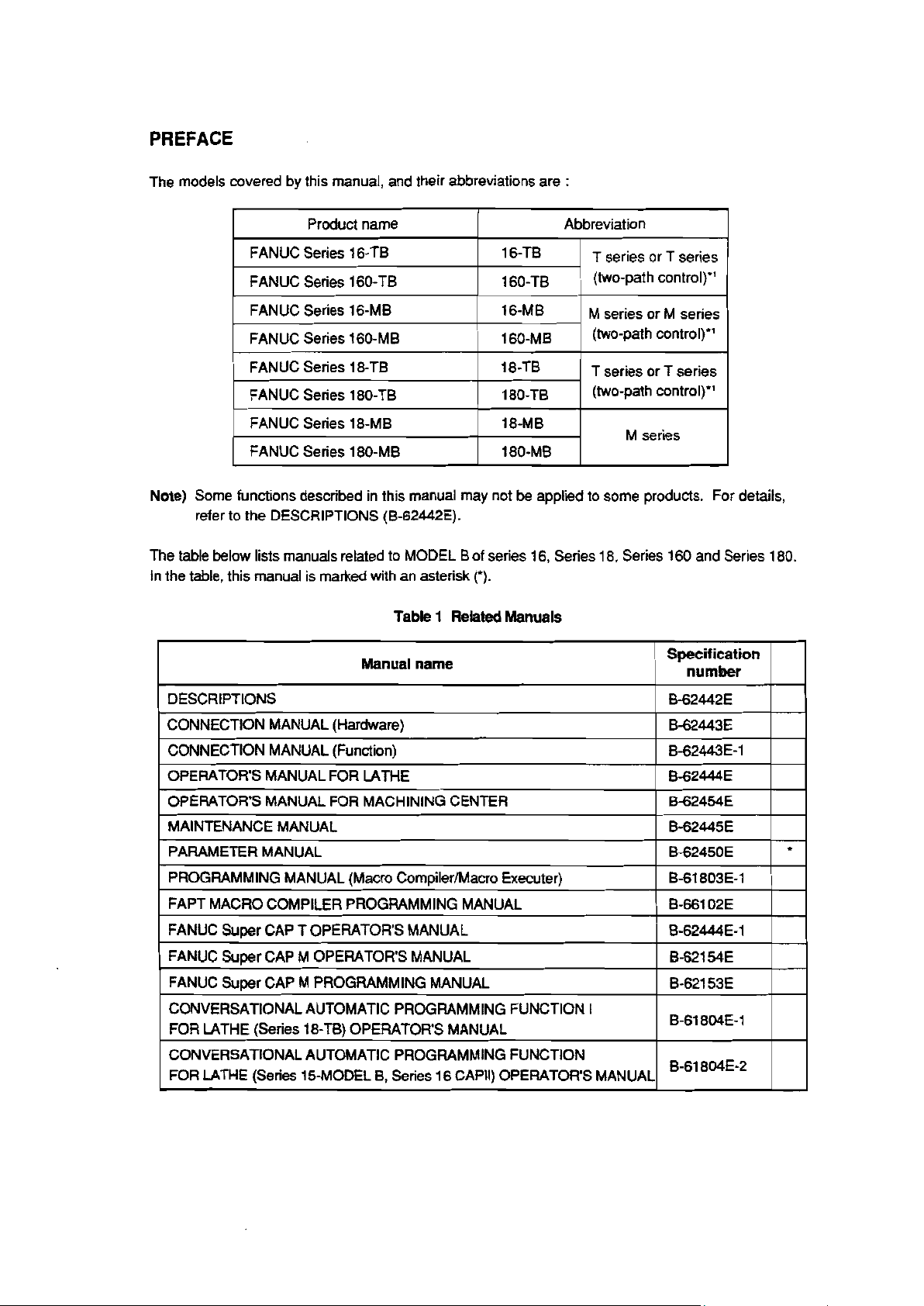
The models covered by this manual, and their abbreviations are :
1
FANUC Series 16.TB
FANUC Series 160.TB
I
FANUC Series 16.MB
I
FANUC Series 160.MB
I
FANUC Series 18-TB 180TB
FANUC Series 180-TB 180-TB
FANUC Series 18.MB 180MB
I
FANUC Series 180.MB 1800MB
Note) Some functions described in this manual may not be applied to some products. For details,
refer to the DESCRIPTIONS (B-62442E).
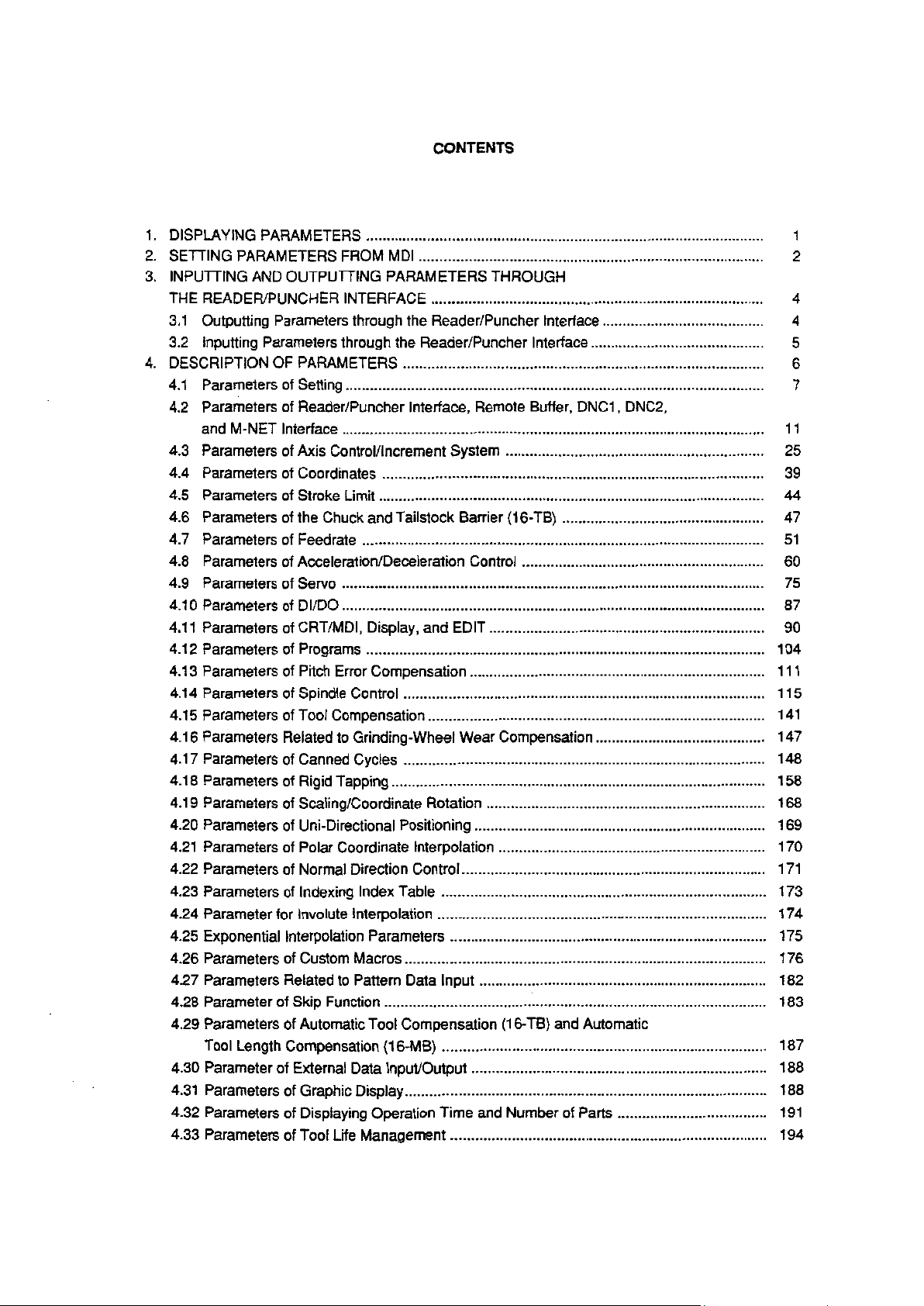
The table below lists manuals related to MODEL B of series 16, Series 18, Series 160 and Series 180.
In the table, this manual is marked with an asterisk (‘).
DESCRIPTIONS
I
1 CONNECTION MANUAL (Hardware)
1 CONNECTION MANUAL (Function)
OPERATOR’S MANUAL FOR LATHE
OPERATOR’S MANUAL FOR MACHINING CENTER
MAINTENANCE MANUAL
I
PARAMETER MANUAL
PROGRAMMING MANUAL (Macro Compiler/Macro Executer)
Product name 0 Abbreviation
I
I
I
Table 1 Related Manuals
Manual name
160TB
1600TB
160MB
1600MB
T series or T series
two-path control)”
I (
M series or M series
1 (two-path control)*’
T series or T series
(two-path control)‘l
M series
Specification
number
B62442E
I
B-62443E
I
1 B-62443E-I -11
B-62444E
B-62454E
B-62445E
I
B-62450E
B-61 803E-1
I I
I I
I I
I I
l
FAPT MACRO COMPILER PROGRAMMING MANUAL
FANUC Super CAP T OPERATOR’S MANUAL
FANUC Super CAP M OPERATOR’S MANUAL
1 FANUC Super CAP M PROGRAMMING MANUAL
CONVERSATIONAL AUTOMATIC PROGRAMMING FUNCTION I
FOR LATHE (Series 18.TB) OPERATOR’S MANUAL
CONVERSATIONAL AUTOMATIC PROGRAMMING FUNCTION
FOR LATHE (Series 15MODEL B, Series 16 CAPII) OPERATOR’S MANUAL
B-661 02E ~~ 7-1
I
’ B-62444EE-1
B-621 54E
B-621 53E
I
B-61 804E-1
B-61 804E2
-11
I I
I1
Page 4
CONTENTS
DISPLAYING PARAMETERS . . . . . . . . . . . . . . . . . . . . . . . . . . . . . . . . . . . . . . . . . . . . . . . . . . . . . . . . . . . . . . . ..*...**...........................
1.
.
2
SETTING PARAMETERS FROM MDI
.
3
INPUTTING AND OUTPUTTING PARAMETERS THROUGH
THE READER/PUNCHER INTERFACE
3.1 Outputting Parameters through the Reader/Puncher Interface
Inputting Parameters through the Reader/Puncher Interface
3.2
.
DESCRIPTION OF PARAMETERS
4
4.1 Parameters of Setting
.......................................................................................................
.....................................................................................
..................................................................................
........................................
...........................................
.........................................................................................
4.2 Parameters of Reader/Puncher Interface, Remote Buffer, DNCl, DNC2,
and M-NET Interface
Parameters of Axis Control/increment System
4.3
........................................................................................................
................................................................
4.4 Parameters of Coordinates ..............................................................................................
4.5 Parameters of Stroke Limit ...............................................................................................
Parameters of the Chuck and Tailstock Barrier (16.TB) ..................................................
4.6
4.7 Parameters of Feedrate
4.8 Parameters of Acceleration/Deceleration Control
4.9 Parameters of Servo
4.10 Parameters of Dl/DO
4.11 Parameters of CRT/MDI, Display, and EDIT
4.12 Parameters of Programs
4.13 Parameters of Pitch Error Compensation
4.14 Parameters of Spindle Control
4.15 Parameters of Tool Compensation
4.16 Parameters Related to Grinding-Wheel Wear Compensation
4.17 Parameters of Canned Cycles
4.18 Parameters of Rigid Tapping
4.19 Parameters of Scaling/Coordinate Rotation
4.20 Parameters of Uni-Directional Positioning
4.21 Parameters of Polar Coordinate Interpolation
4.22 Parameters of Normal Direction Control
4.23 Parameters of Indexing Index Table
4.24 Parameter for Involute Interpolation
4.25 Exponential Interpolation Parameters
4.26 Parameters of Custom Macros
4.27 Parameters Related to Pattern Data Input
4.28 Parameter of Skip Function
...................................................................................................
............................................................
........................................................................................................
........................................................................................................
....................................................................
..................................................................................................
.........................................................................
.........................................................................................
...................................................................................
..........................................
.........................................................................................
............................................................................................
.....................................................................
........................................................................
..................................................................
...........................................................................
................................................................................
.................................................................................
..............................................................................
.........................................................................................
.......................................................................
..............................................................................................
4.29 Parameters of Automatic Tool Compensation (16-TB) and Automatic
Tool Length Compensation (16.MB)
4.30 Parameter of External Data Input/Output
4.31 Parameters of
Graphic Display
4.32 Parameters of Displaying Operation Time and Number of Parts
4.33 Parameters of
Tool Life Management
................................................................................
.........................................................................
.........................................................................................
.....................................
..............................................................................
1
2
11
25
39
44
47
51
60
75
87
90
104
111
115
141
147
148
158
168
169
170
171
173
174
175
176
182
183
187
188
188
191
194
Page 5
4.34
Parameters of Position Switch Functions
Parameters of Manual Operation and Automatic Operation
4.35
Parameters of Manual Handle Feed, Handle Interruption and Handle Feed in Tool
4.36
Axial Direction
4.37
Parameters Related to Butt-Type Reference Position Setting .........................................
4.38
Parameters of Software Operator’s Panel
4.39
Parameters of Program Restart
4.40
Parameters of High-Speed Machining (High-Speed Cycle
Machining/High-Speed Remote Buffer) ............................................................................
4.41
Parameters of Polygon Turning ........................................................................................
4.42
Parameters of the External Pulse Input ............................................................................
4.43
Parameters of the Hobbing Machine and Electronic Gear Box
4.44
Parameters of Axis Control by PMC .................................................................................
4.45
Parameters of Two-path Control
4.46
Parameters for Checking Interference between Tool Posts (Two-path Control)
4.47
Parameters Related to Path Axis Reassignment
4.48
Parameters for Angular Axis Control ................................................................................
4.49
Parameters Related to B-Axis Control ..............................................................................
4.50
Parameters of Simple Synchronous Control ....................................................................
4.51
Parameters of Related to Check Termination ..................................................................
4.52
Parameters of High-Speed High-Precision Contour Control by RISC (16 MB)
Other Parameters
4.53
4.54
Parameters for Maintenance
APPENDIX 1 CHARACTER CODE LIST
..................................................................................................................
.......................................................................................
......................................................................................
.............................................................................................................
............................................................................................
.........................................................................
............................................
........................................................................
........................................
.............................................................
. . . . . . . . . . . . . . . . . . . . . . . . . . . . . . . . . . . . . . . . . . . . . . . . . . . . . . . . . . . . . . . . . . . . . . . . . . . . . . . . .
..............
................
196
199
200
202
204
206
207
209
212
212
216
220
221
223
232
233
236
239
240
245
248
249
Page 6
I.
DISPLAYING PARAMETERS
1 l DISPLAYING PARAMETERS
Follow the procedure below to display parameters.
@
Press the SYSTEM function key on the
the SYSTEM function key once, then the
then selected.
Function keys
Note)
Pressing the SYSTEM function key displays section select soft keys including
CRT/MD1
PARAM
as many times as required, or alternatively, press
section select soft key. The parameter screen is
PARAM.
: >
I
i
MEM STRT
[PARAM]
Return menu key Soft keys Continuous menu key
@
The parameter screen consists of multiple pages. Use step (a) or (b) to display the page that contains
Ml-N
FIN
*** lOzO2:30
[ DGNOS ] [ PMC ][SYSTEM] [(OPRT)]
I
Soft
/t
(section select)
j
key display
the parameter you want to display.
Use the page select key or the cursor move keys to display the desired page.
(a)
(b)
Enter the data number of the parameter you want to display from the keyboard, then press the
NO.SRH soft
key. The parameter page containing the specified data number appears with the
cursor positioned at the data number. (The data is displayed in reverse video.)
Note)
If key entry is started with the section select soft keys displayed, they are replaced automatically
by operation select soft keys including
NO.SRH.
Pressing the (OPRT) soft key can also cause the
operation select keys to be displayed.
/
i >
1410
i
i
MEM STRT MTN FIN
\
[NO. SRH][ ON:1 ]
*** lOzO2:34
[OFF:0 ]
[+INPUTJ [INPUTJ
Data
f-
\
the keyboard
1
Soft key display
(operation select)
entered from
PARAMETER (FEEDRATE) 00001 NO0010
1401
1402
1410 DRY
1412
1420 RAPID
>
MEM
STRT
[NOSRH] [
RDR
0 0 0 0
JRV
0 0 0 0
RUN
FEEDRATE
FEEDRATE X
MTN FIN
*** 10102:35
ON:1 ] [OFF:0 ] [+INPUTJ [INPUT)
JZR
0
0
Y
z
0 0 0
0 0 0
-/
RPD
09
0
15000
15000
15000
Cursor
/
0
Page 7
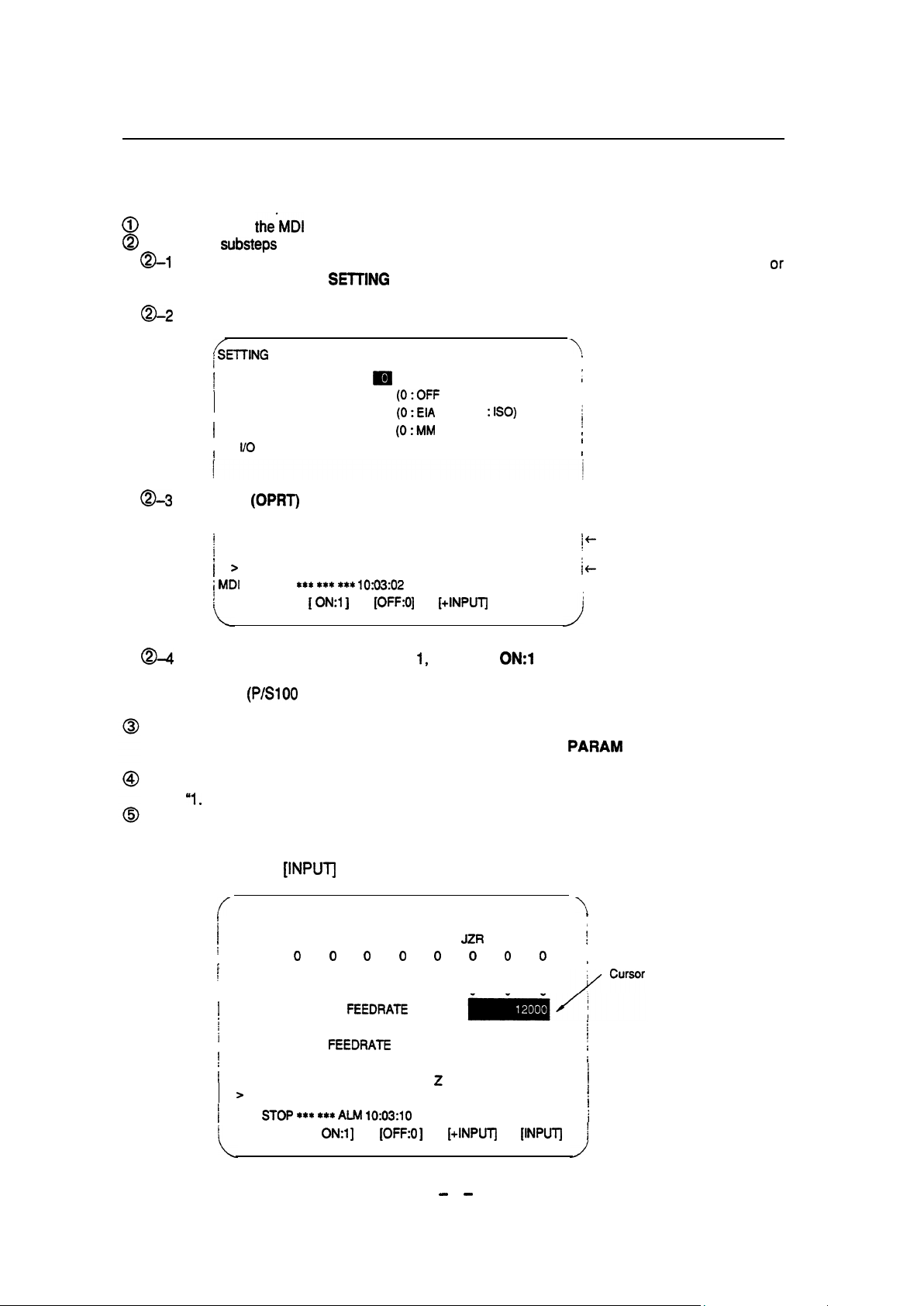
2. SETTING PARAMETERS FROM MDI
Follow the procedure below to set parameters.
2.
SETTING PARAMETERS FROM MDI
@@Place the NC in
Follow the
@I
substeps
To display the setting screen, press the SETTING function key as many times
alternatively press the
The first page of the setting screen appears.
Position the cursor on “PARAMETER WRITE” using the cursor move keys.
B-2
f
I
SElTlNG (HANDY)
I
PARAMETER WRITE = m (0 : DISABLE 1 : ENABLE)
’
/
TV CHECK
PUNCH CODE
I
INPUT UNIT
I
i
l/O
I
a-3
Press the
i
i
>
1410
I
i
MDI
STOP
i
[NO. SRH]\[ ON:1 ]
Q-4
To set “PARAMETER WRITE=” to I, press the
press the INPUT soft key. From now on, the parameters can be set. At the same time an alarm
condition
(P/S100
the’MDI
mode or the emergency stop state.
below to enable writing of parameters.
CHANNEL
(OPRT)
***
SETTING
soft key to display operation select soft keys.
*s*
*** 10:03:02
function key once, then the SETTING section select soft key.
00001 NO0010
[+lNPUT]
1 :ON)
1
: ISO)
1 : INCH)
[INPUTJ
ON:1
soft key, or alternatively enter 1 and
= 0
(0:OFF
= 0
(0:ElA
= 0 (0:MM
= 0 (O-3 : CHANNEL NO.)
[OFF:01
PARAMETER WRITE ENABLE) occurs in the CNC.
as required,
\
s
;
I
,
1
1
I
I
1 +
Data entered from the keyboard
i +
Soft key display (operation select)
or
To display the parameter screen, press the
SYSTEM
function key as many times as required, or
alternatively press the SYSTEM function key once, then the
(See “I. Displaying Parameters.“)
Display the page containing the parameter you
(See
“I.
Displaying Parameters.“)
Enter data, then press the
INPUT soft
key. The parameter indicated by the cursor is set to the entered
want
to set, and position the cursor on the parameter.
data.
[Example] 12000
f
I
PARAMETER (FEEDRATE)
I
I
i
;
i
I
I
i
I
i
i
i
f
I
>
1
MDI
[NO. SRH][ ON:1 ]
[INPUTJ
1401
0
1402
0
1410
DRY RUN
1412
1420 RAPID
SVOP
*** **= ALM 10:03:10
RDR
0 0 0 0
JRV
0 0
FEEDRATE
FEEDRATE
0 0
[OFF:0 ]
00001 NO0010
JZR
0
0
X
Y
2
[+INPUTj [INPUTJ j
RPD
0 0
0 0
0
15000
15000
15000
PARAM
\
’
I
j
I
f
/
i
I
i
I
1
8
t
i
I
section select soft key.
- -
2
Page 8
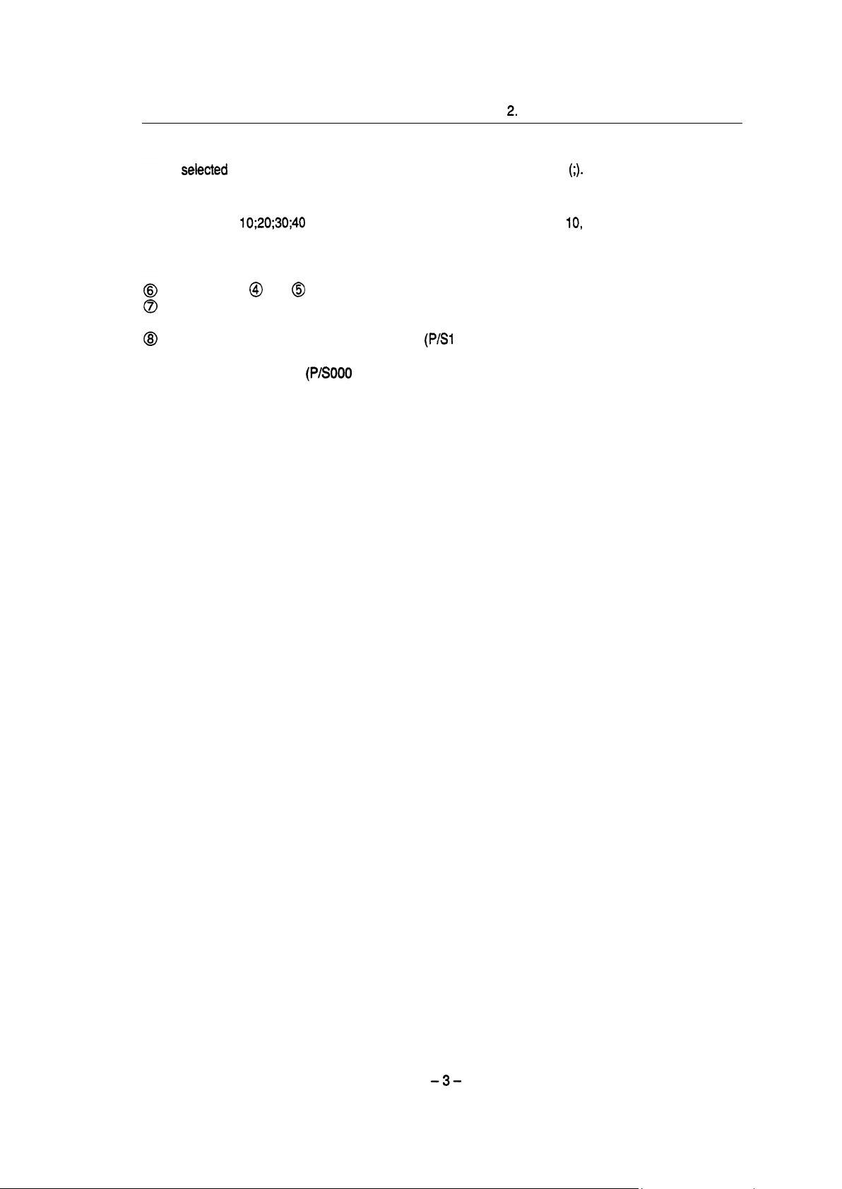
2.
SETTING PARAMETERS FROM MDI
Data can be entered continuously for parameters, starting at the
seiected
parameter, by separating each data
item
with a semicolon
(;).
[Example]
Entering
20, 30, and 40 to parameters in order starting at the parameter
indicated by the
Repeat steps @ and @ as required.
If parameter setting is complete, set
further
Reset
10;20;30;40
and
pressing the INPUT key assigns values
cursor.
“PARAMETER
parameter setting.
the NC to release the alarm condition
(P/S1
IO,
WRITE=” to 0 on the setting screen to disable
00).
If an alarm condition
continuing operation.
Note) The bits left blank in4. DESCRIPTION OF PARAMETERS and the parameter numbers that appear
on the CRT screen but are not found in the parameter list are resewed for future expansion. They
must always be 0.
(P/SO00
PLEASE TURN OFF
POWER)
occurs in the NC, turn it off before
Page 9
3. INPUTTING AND OUTPUTTING PARAMETERS THROUGH
THE READER/PUNCHER INTERFACE
3. INPUTTING AND OUTPUTTING PARAMETERS THROUGH
This section explains the parameter input/output procedures for input/output devices connected to the
reader/puncher interface.
It
The following description assumes the input/output devices are ready for input/output.
parameters peculiar to the input/output devices, such as the baud rate and the number of stop bits, have
been set in advance.
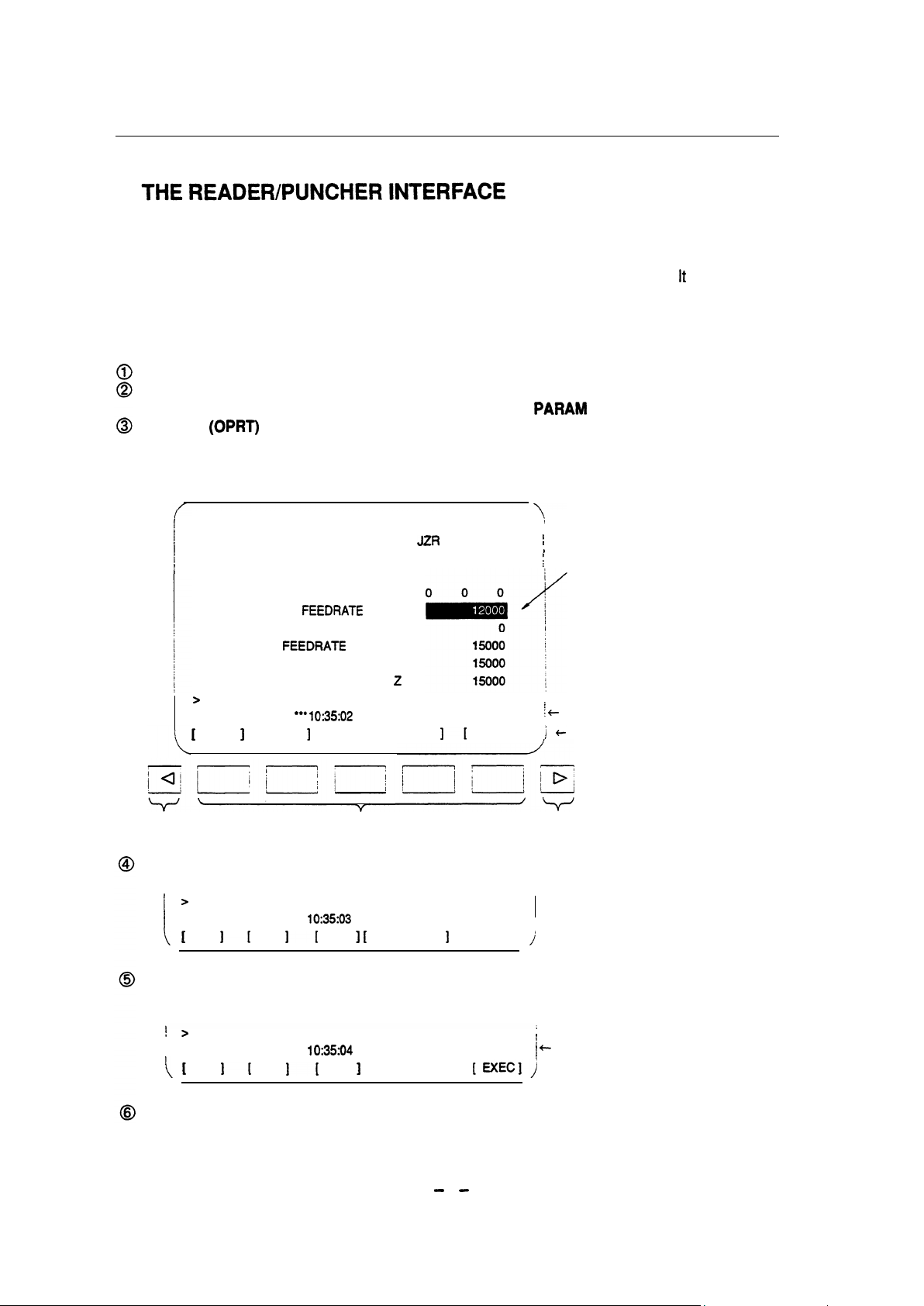
3.1 Outputting Parameters through the Reader/Puncher Interface
Select the EDIT mode.
To select the parameter screen, press the SYSTEM function key as many times as required, or
alternatively press the SYSTEM function key once, then the PARAM section select soft key.
Press the
located at the right-hand side of the soft keys to display another set of operation select keys including
PUNCH.
(OPRT)
soft key to display operation select soft keys, then press the forward menu key
also assumes
PARAMETER (FEEDRATE)
1401
1402 JRV
1410 DRY RUN
1412
1420 RAPID
RDR
0 0
0 0
FEEDRATE
FEEDRATE X
0
0
0 0
0 0
Y
z
00001 NO0010
JtR
0 0 0
RPD
\
I
0
;
Cursor
>
! t
EDIT STOP l ** l -*
[
Return menu key
*-+ lo:3502
]
[READ ] [PUNCH] [
Soft keys
I[
1
Continuous menu key
State display
c- Soft key display (operation select)
Pressing the PUNCH soft key changes the soft key display as shown below:
>
I
1
EDIT STOP l ** l ** l **
II
\ [
I[
lo:3503
] [
CANCEL
]
[ EXEC]
/
Press the EXEC soft key to start parameter output. When parameters are being output, “OUTPUT”
blinks in the state display field on the lower part of the screen.
!
>
EDIT STOPl *+ l +* l **
I
I[
i
11
t 0:35:04
OUTPUT
]
[CANCEL]
[EXEC],j
t
1 +
OUTPUT blinking
When parameter output terminates, “OUTPUT” stops blinking. Press the RESET key to interrupt
parameter output.
- -
4
Page 10
3.2 Inputting Parameters through the Reader/Puncher interface
3.2 Inputting Parameters through the Reader/Puncher Interface
Place the NC in the emergency stop state.
@
0 Enable parameter writing.
To display the setting screen, press the SETTING function key as many times as required, or
alternatively press the SElTlNG function key once, then the SETTING section select soft key.
The first page of the setting screen appears.
Position the cursor on “PARAMETER WRITE” using the cursor move keys.
Press the (OPRT) soft key to display operation select soft keys.
To set “PARAMETER WRITE=” to 1, press the ON:1 soft key, or alternatively enter 1, then press
the INPUT soft key. From now on, parameters can be set. At the same time an alarm condition
(P/S100 PARAMETER WRITE ENABLE) occurs in the NC.
To select the parameter screen, press the SYSTEM function key as many times as required, or
alternatively press the SYSTEM key once, then PARAM soft key.
Press the (OPRT) soft key to display operation select keys, then press the forward menu key located
at the right-hand side of the soft keys to display another set of operation select soft keys including
READ.
>
j
, EDIT STOP m A!Jvl 10:37:30
i
1 [READ I [PUNCH1 [ I 1
[
Soft keys
i
I c- State display
I
Soft key display
1
Continuous menu key
t
Pressing the READ soft key changes the soft key display as shown below:
I
: EDIT STOP - Altv’l 10:37:30
11 3 1
] [ CANCEL
[
EXEC]
]
I
/
Press the EXEC soft key to start inputting parameters from the input/output device. When parameters
are being input, “INPUT” blinks in the state display field on the lower part of the screen.
>
j EDIT STOP - Al&l 10:37:30
II II
]
INPUT
[CANCEL] [EXEC])
When parameter input terminates, “INPUT” stops blinking.
I
1 t INPUT blinking
Press the RESET key to interrupt
parameter input.
When parameter read terminates, “INPUT” stops blinking, and an alarm condition (P/SOOO) occurs
in the NC. Turn it off before continuing operation.
Page 11
4. DESCRIPTION OF PARAMETERS
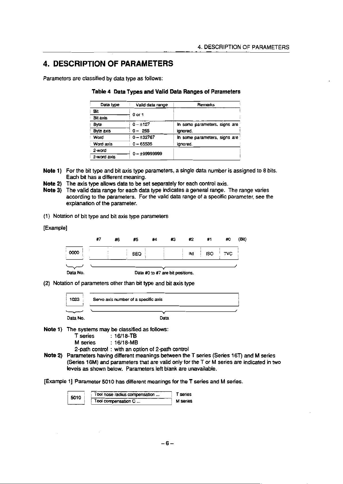
Parameters are classified by data type as follows:
Table 4 Data Types and Valid Data Ranges of Parameters
!
4
Data type
1 Bit
: Bit axis
iv*
b
(
Byteaxis
I
I word
I
:
Word axis
l 2-word
i 2-word axis
i
hddata range [
I
1 Oorl
t
i O-+127
! o- 255
1 0 - k32767
i 0 - 65535
I
1 0 -299999999
I
4. DESCRIPTION OF PARAMETERS
Remarks
1
I
In some parameters, signs are
ignored.
In some parameters, signs are !
ignored.
;
I
0
:
I
1
j
1
4
8
i
I
Note 1)
For the bit type and bit axis type parameters, a single data number is assigned to 8 bits.
Each bit has a different meaning.
Note 2)
Note 3)
The axis type allows data to be set separately for each control axis.
The valid data range for each data type indicates a general range. The range varies
according to the parameters. For the valid data range of a specific parameter, see the
explanation of the parameter.
(1) Notation of bit type and bit axis type parameters
[Example]
l
(W
I
1
j i
I
IoooOi :
; 1.
#7
#6
I
,
t I
#5
I
i SEQ ;
##4 ##3 #2 #1
I
I
/
I
I
i
1 IN1
/
##O
/
i IS0 / Tvc ;
I I
I
\
Data No. Data ##0 to #y7 are bit positions.
(2) Notation of parameters other than bit type and bit axis type
;
I :
I
1
1023 ; ; Servo axis number of a specific axis
I
I i
Data No. Data
t
!
I
Note 1) The systems may be classified as follows:
T series : 16/l 8-TB
M series : 16/l 8-MB
2-path control : with an option of 2-path control
Note 2) Parameters having different meanings between the T series (Series 16T) and M series
(Series 16M) and parameters that are valid only for the T or M series are indicated in two
levels as shown below. Parameters left blank are unavailable.
[Example l] Parameter 5010 has different meanings for the T series and M series.
I
5010 I
8
i Tool nose radius compensation ..;
! Tool compensation C . . .
)
- -
1 T
1 M series
6
series
Page 12
4.1 Parameters of Setting
[Example 21 DPI is a parameter common to the M and T series, but GSB and GSC are parameters valid
only for the T series.
157 #6
GSC GSB
#O
T series
M series
[Example 31 The following parameter is provided only for the M series.
,
i ’
I
’ ;
;14501 :
-
; Fl digit feed . . .
I
i T series
i M series
4.1 Parameters of Setting
#?
#6
Setting entry is acceptable.
Data type: Bit
TVC
TV check
0: Not performed
1: Performed
IS0
Code used for data output
0: EIA code
1: IS0 code
INI
Unit of input
0: In mm
1: In inches
Automatic insertion of sequence numbers
SEQ
0: Not performed
1: Performed
#5
##4 #3 #2 #I
.
#O i
(W
When a program is prepared by using MDI keys in the part program storage and edit mode, a
Note)
sequence number can automatically be assigned to each block in set increments. Set the
increment to parameter 3216.
#l #O i
I
FCV !
I
!
I
i
I
(W
j 0001 ; ;
: 8
I
L
#7 #6 I#5
6
j
I
I
/
#4
I
j
#3 #2
!
j
I
I
I
Setting entry is acceptable.
Data type: Bit
FCV Tape format
0: Series 16 standard format
1: Series 15 format
Note I)
Programs created in the Series 15 tape format can be used for operation on the following
functions:
Subprogram call M98
(1)
Thread cutting with equal leads G32 (T series)
(2)
Canned cycle G90, G92, G94 (T series)
(3)
Multiple repetitive canned cycle G71 to G76 (T series)
(4)
Drilling canned cycle G73, G74, G76, G80 to G89 (M series)
(5)
Cutter compensation C (M series)
(6)
Page 13
4.1 Parameters of Setting
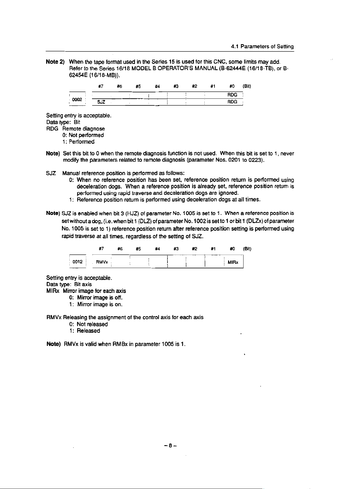
Note 2) When the tape format used in the Series 15 is used for this CNC, some limits may add.
Refer to the Series 16/l 8 MODEL B OPERATOR’S MANUAL (B-62444E (16/l 8-TB), or B-
62454E (16/l 8-MB)).
RDG :
(Bit)
,
I
I
’ 0002 i , sJz f
I
#7
i :
!
#6
#5 #4
i
I
#3 #2
1
,
I ! j
I
I
1
,
#l #O
I
I
’ RDG j
Setting entry is acceptable.
Data type: Bit
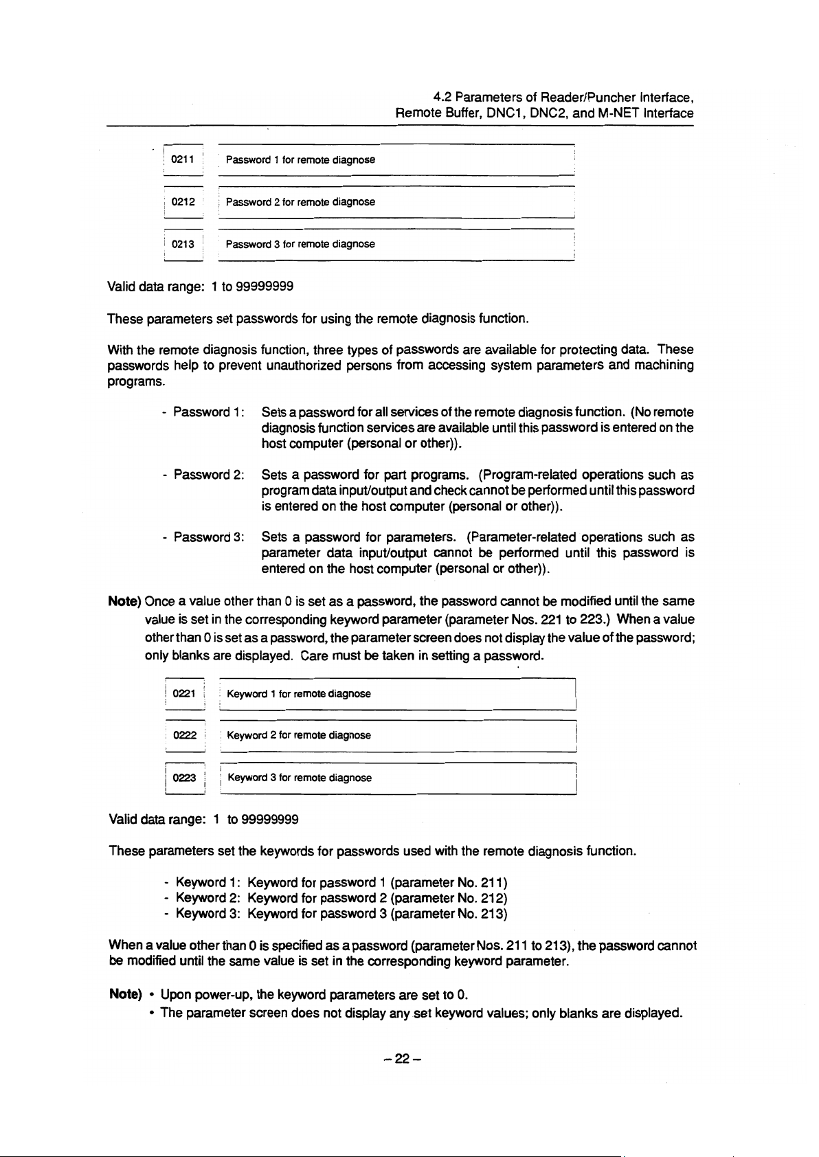
RDG Remote diagnose
0: Not performed
1: Performed
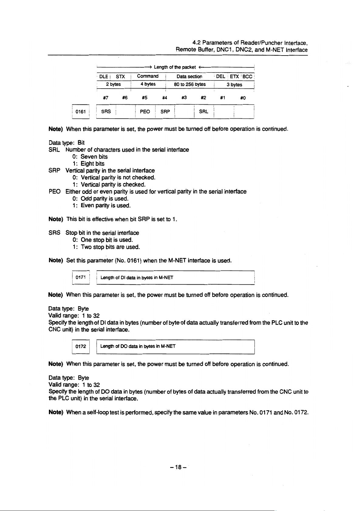
Note) Set this bit to 0 when the remote diagnosis function is not used. When this bit is set to 1, never
modify the parameters reiated to remote diagnosis (parameter Nos. 0201 to 0223).
SJZ Manual reference position is performed as follows:
0: When no reference position has been set, reference position return is performed using
deceleration dogs. When a reference position is already set, reference position return is
performed using rapid traverse and deceleration dogs are ignored.
1: Reference position return is performed using deceleration dogs at all times.
Note) SJZ is enabled when bit 3
(HJZ) of parameter No. 1005 is set to 1. When a reference position is
set without a dog, (i.e. when bit 1 (DLZ) of parameter No. 1002 is set to 1 or bit 1 (DLZx) of parameter
No. 1005 is set to 1) reference position return after reference position setting is performed using
rapid traverse at all times, regardless of the setting of SJZ.
#7 #6 #5
I
/ 0012 ! ; RMVx j
:
/
!
I
I
I
i
\
##4 #3 #I2 #l #0 i
I
1
I
,
I
I
I
I
!
1 MRx
(B t)
Setting entry is acceptable.
Data type: Bit axis
MlFIx Mirror image for each axis
0: Mirror image is off.
1: Mirror image is on.
RMVx Releasing the assignment of the control axis for each axis
0: Not released
1: Released
Note) RMVx is valid when RMBx in parameter 1005 is 1.
- -
8
Page 14
4.1 Parameters of Setting
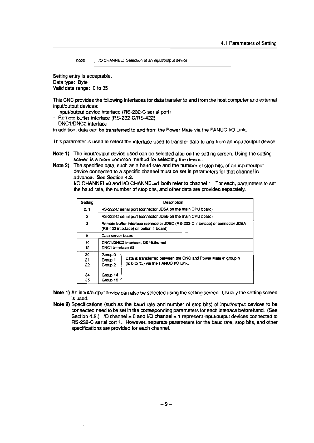
0020 !
l/O CHANNEL: Selection of an input/output device
I
i
Setting entry is acceptable.
Data type: Byte
Valid data range: 0 to 35
This CNC provides the following interfaces for data transfer to and from the host computer and external
input/output devices:
- Input/output device interface (RS-232-C serial port)
- Remote buffer interface (RS-232.CYRS-422)
- DNCl /DNC2 interface
In addition, data can be transferred to and from the Power Mate via the FANUC I/O Link.
This parameter is used to select the interface used to transfer data to and from an input/output device.
Note 1)
The input/output device used can be selected also on the setting screen. Using the setting
screen is a more common method for selecting the device.
Note 2)
The specified data, such as a baud rate and the number of stop bits, of an input/output
device connected to a specific channel must be set in parameters for that channel in
advance. See Section 4.2.
I/O CHANNEL=0 and l/O CHANNEL=1 both refer to channel I. For each, parameters to set
the baud rate, the number of stop bits, and other data are provided separately.
[
Setting r
1 k-232-C serial port (connector JD5A on the main CPU board)
091
I ~~~ ~~~
2 I RS-232-C serial port (connector JD5B on the main CPU board)
I
Remote buffer interface (connector JDSC (RS-232-C interface) or connector JDGA
I 3 I
1 5 1 Dataserver board
20
21
22
(RS-422 interface) on option 1 board)
DNWDNC2 interface, OSI-Ethernet
DNCl interface #2
Group 0
Group 1
Group 2
Data is transferred between the CNC and Power Mate in group n
(n: 0 to 15) via the FANUC l/O Link.
Description
I
I
I
I
I
34
35
GroLp 14
Group 15
I
Note 1) An input/output device can also be selected using the setting screen. Usually the setting screen
is used.
Note 2) Specifications (such as the baud rate and number of stop bits) of input/output devices to be
connected need to be set in the corresponding parameters for each interface beforehand. (See
Section 4.2.) I/O channel = 0 and l/O channel =
1 represent input/output devices connected to
RS-232-C serial port I. However, separate parameters for the baud rate, stop bits, and other
specifications are provided for each channel.
- -
9
Page 15
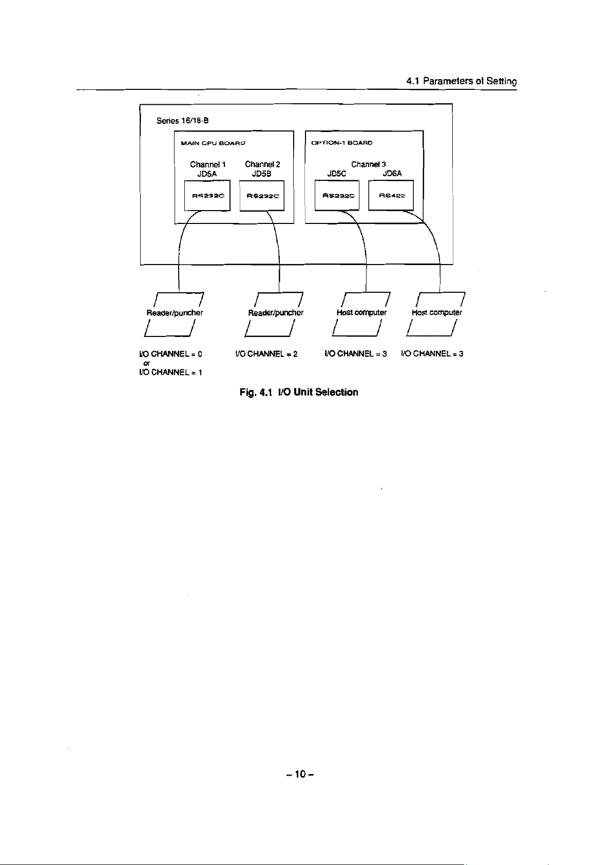
Series 16/l 8-B
4.1 Parameters of Seth
Reader/puncher
l/O CHANNEL = 0
l/&HANNEL = 1
Reader/puncher Host computer
Host computer
u uu
l/O CHANNEL = 2 VO CHANNEL = 3 I/O CHANNEL = 3
Fig. 4.1 l/O Unit Selection
Page 16
4.2 Parameters of Reader/Puncher Interface,
Remote Buffer, DNCl, DNCZ, and M-NET Interface
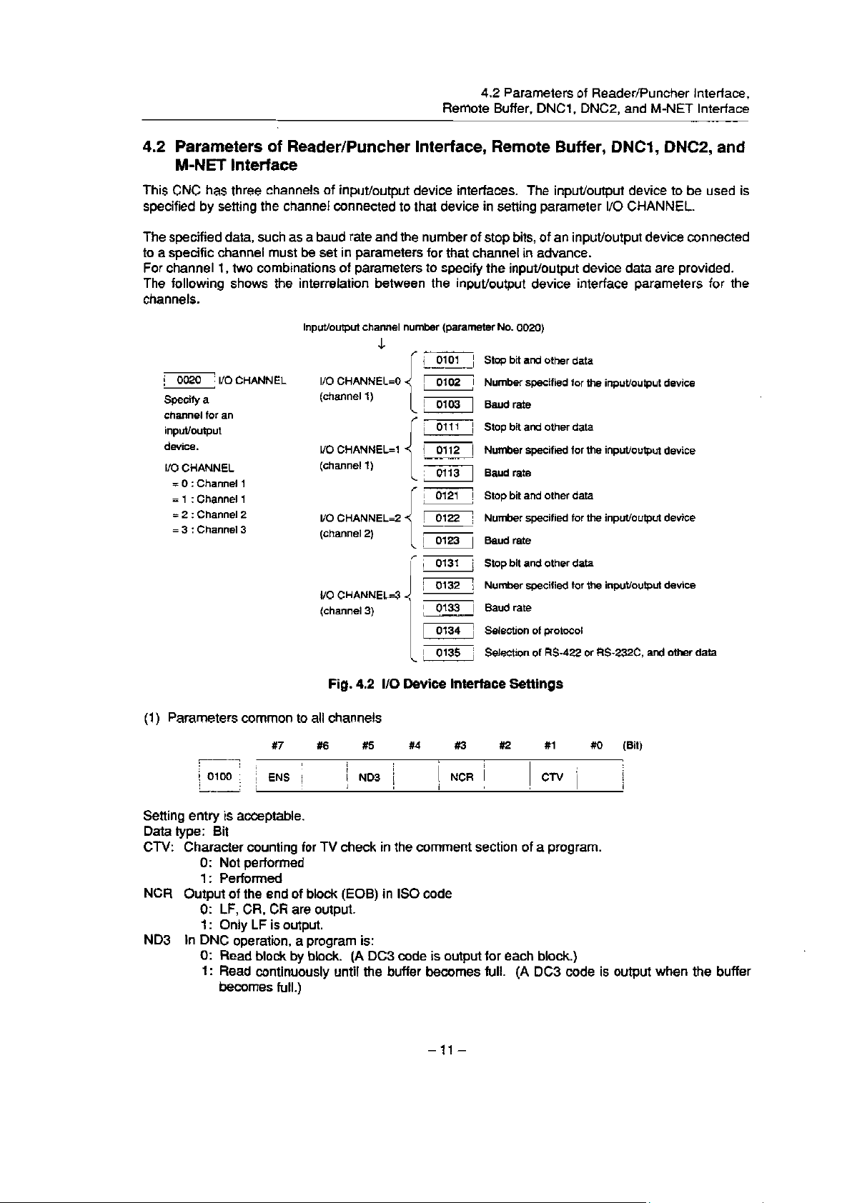
4.2 Parameters of Reader/Puncher Interface, Remote Buffer, DNCl, DNC2, and
M-NET interface
This CNC has three channels of input/output device interfaces. The input/output device to be used is
specified by setting the channel connected to that device in setting parameter 110 CHANNEL.
The specified data, such as a baud rate and the number of stop bits, of an input/output device connected
to a specific channel must be set in parameters for that channel in advance.
For channel 1, two combinations of parameters to specify the input/output device data are provided.
The following shows the interrelation between the input/output device interface parameters for the
channels.
Input/output channel number (parameter No. 0020)
Stop bit and other data
! 0020 i I/O CHANNEL
Specify a
channel for an
input/output
device.
I/O CHANNEL
= 0 : Channel
= 1 :
Channel
: Channel
= 2
: Channel 3
3
=
1
1
2
I/O CHANNEL=0
(channel 1)
l/O CHANNEL=1
(channel 1)
l/O CHANNEL=2
j
iT/
I
Number specified for the input/output device
Baud rate
Stop bit and other data
Number specified for the input/output device
Baud rate
Stop bit and other data
Number specified for the input/output device
Baud rate
Stop bit and other data
Number specified for the input/output device
Baud rate
Selection of protocol
Selection of M-422 or RS232C, and other data
Fig. 4.2 I/O Device Interface Settings
(1) Parameters common to all channels
, 1
9
/ 0100 ;
!A
I
I
j
#7 #6
I
ENS /
#5
i
/ ND3 /
##4 #3 #2 81
I
I
I
/ NCR 1
i
I i
Setting entry is acceptable.
Data type: Bit
Character counting for W check in the comment section of a program.
CTV:
0: Not performed
1: Performed
NCR Output of the end of block (EOB) in IS0 code
0: LF, CR, CR are output.
1: Only LF is output.
In DNC operation, a program is:
ND3
0: Read block by block. (A DC3 code is output for each block.)
1: Read continuously until the buffer becomes full. (A DC3 code is output when the buffer
becomes full .)
\
clv :
#O i
WI
,
/
i
i
Page 17
4.2 Parameters of Reader/Puncher Interface,
Remote Buffer, DNCI, DNC2, and M-NET interface
Note) in general, reading is performed more efficiently when ND3 = 1. This specification reduces the
number of buffering interruptions caused by reading of a series of blocks specifying short
movements. This in turn reduces the effective cycle time.
ENS: Action taken when a NULL code is found during read of EIA code
0: An aiarm is generated.
1: The NULL code is ignored.
(2) Parameters for channel 1 (I/O CHANNEL=O)
#I #O
1
,
j
SB2 i
(Bit)
1
1
/
m
0101 j
1,
#7
1
NFD
#6 #5
i j
I
I
I
I
#4 #3 #Q
i
i
I
) AS!
I
/
1
Data type: Bit
The number of stop bits
SB2
0: 1
1: 2
Code used at data input
ASI
0: EIA or IS0 code (automatically distinguished)
1: ASCH code
Feed before and after the data at data output
NFD
0: output
I : Not output
(Note) When input/output devices other than the FANUC PPR are used, set NFD to 1.
I
j 0102 j
I
! L
Data type: Byte
Set the number specified for the input/output device used when the I/O CHANNEL is set to 0, with one of
the set values listed in Table 4.2 (a).
i Number specified for the input/output device (when the l/O CHANNEL is
!
set to 0)
1
/
!
,
Table 4.2 (a) Set Value and Input/Output Device
I
!
I
I
j
i
i
I
,
I
I
I
I
I
1
/
I ,
I
i :
i 0103 i
I
I
I
:
i Set value : Input/output device
! 0 ; RS-232-C (Used control codes DC1 to DC4)
i
:
I
i
f 3 j FANUC FLOPPY CASSETTE ADAPTOR
I
!
j 4
i
; 6
i
I
!
Baud rate (when the I/O CHANNEL is set to 0)
FANUC CASSETTE ADAPTOR 1 (FANUC CASSElTE Bl/B2)
1
2 i
FANUC CASSE-ITE ADAPTOR 3 (FANUC CASSEI-I-E Fl)
i
FANUC PROGRAM FILE Mate, FANUC FA Card Adapter
i
FANUC SYSTEM P-MODEL H, FANUC Handy File
j RS-232-C (Not used control codes DC1 to DC4) 1
5 ; ‘Portable tape reader
j FANUC PPR
FANUC SYSTEM P-MODEL G, FANUC SYSTEM P-MODEL H
[
Data type: Byte
Set the baud rate of the input/output device used when the I/o CHANNEL is set to 0, with a set value in
Table 4.2 (b).
-12-
Page 18
4.2 Parameters of Reader/Puncher interface,
Remote Buffer, DNCI , DNC2, and M-NET Interface
Table 4.2
1 set value f Baud rate (bps) !
r --2-- I
f 3 i 110 I I , 9 ; 2400
1 i 4
i 4 i 1% ! :
1 5 j
* 1
j 6
j 300 i 1 12 j 19200 !
(b) Baud Rate Settings
] Set value ! Baud rate (bps)
I
;
loo
I
200 j 11 i 9600
8 j 1200
10 j 4800 i
I
(3) Parameters for channel 1 (I/O CHANNEL=1 )
i
1 0111 i
I
c
I
j NFD i
I I
#I7
#6 #5
i
1 .
i
i I
#4
#3 #2
1
ASI 1
1
!
#l
I
I
,
I
1
##o
1 SB2 j
I
i
w
i
Data type: Bit
These parameters are used when I/O CHANNEL is set to 1. The meanings of the bits are the same as
for parameter 0101.
I
/
,
0112
i
; Number specified for the input/output device (when l/O CHANNEL is
i
settol)
: ;
Data type: Byte
Set the number specified for the input/output device used when the l/O CHANNEL is set to 1, with one of
the set vaiues listed in Table 4.2 (a).
.
I
I
;0113! ,
i
Baud rate (when I/O CHANNEL is set to 1)
I 1
Data type: Byte
Set the baud rate of the input/output device used when I/O CHANNEL is set to 1, with a value in Table 4.2
.
(b)
(4) Parameters for channel 2 (I/O CHANNEL=2)
#5 #4 #3 #2 a1 80 i
I
I
I
i
I
I
I
! ASI 1
I
I
I
I
j SB2
I
(W
’ .
I .
0
/ 0121 j ;
!:
I
#7 #6
I
NFD j
Data type: Bit
These parameters are used when I/O CHANNEL is set to 2. The meanings of the bits are the same as
for parameter 0101.
:
0122 i
i
I ,
, to2)
I
- L
/
Number specified for the input/ou@ut device (when l/O CHANNEL is set
!
--
/
Data type: Byte
Set the number specified for the input/output device used when I/O CHANNEL is set to 2, with a value
in Table 4.2 (a).
r
i
0123 i
i
*
,
,
i (
1 Baud rate (when the l/O CHANNEL is set to 2)
! !
9
-- I
Data type: Byte
Set the baud rate of the input/output device used when I/O CHANNEL is set to 2, with a value in Table 4.2
.
(b)
-13-
Page 19
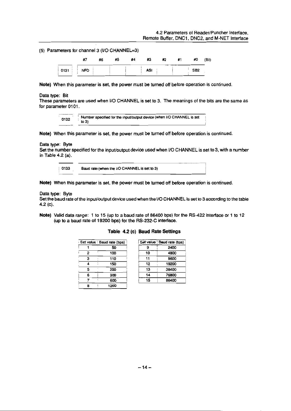
(5) Parameters for channel 3 (I/O CHANNEL=3)
4.2 Parameters of Reader/Puncher Interface,
Remote Buffer, DNCI, DNC2, and M-NET Interface
1 c
/ 0131 f j
I I
I
A.
#7
I
NFD ;
#6 #5 #4
,
1
I
1
j
9
I
/
!
I
#a #2 #1
I
j ASI /
#O (Bit)
[
: SB2 :
,
Note) When this parameter is set, the power must be turned off before operation is continued.
Data type: Bit
These parameters are used when I/O CHANNEL is set to 3. The meanings of the bits are the same as
for parameter 0101.
0132 !
I
u
j Number specified for the input/output device (when I/O CHANNEL is set :
D to3)
I
I
Note) When this parameter is set, the power must be turned off before operation is continued.
Data type: Byte
Set the number specified for the input/output device used when I/O CHANNEL is set to 3, with a number
in Table 4.2 (a).
!
/
0133 :
,
:
Baud rate (when the I/O CHANNEL is set to 3)
I
Note) When this parameter is set, the power must be turned off before operation is continued.
Data type: Byte
Set the baud rate of the input/output device used when the I/O CHANNEL is set to 3 according to the table
4.2 (c).
Note) Valid data range: 1 to 15 (up to a baud rate of 86400 bps) for the RS-422 interface or 1 to 12
(up to a baud rate of 19200 bps) for the RS-232-C interface.
Table 4.2
: Set value ! Baud rate (bps) !
I 1 ;
2 i 100 i
i
3 # t
1 4
/ 5 t
6 1
I
7
1 :
i 8 i
50 1
110
150 /
j
200 ;
300 I
j 600
1200 f
1
Baud Rate Settings
(cl
1 Set value
1 9 1 2400 I
i
’ 10 i
I
i
1
11 ‘i
I
1 12 j
i
13 I 38400
I 14 I
! 15 1 86400
,
! Baud rate (bps) !
4800 /
9600 /
19200 1
!
76800 I
-14-
Page 20
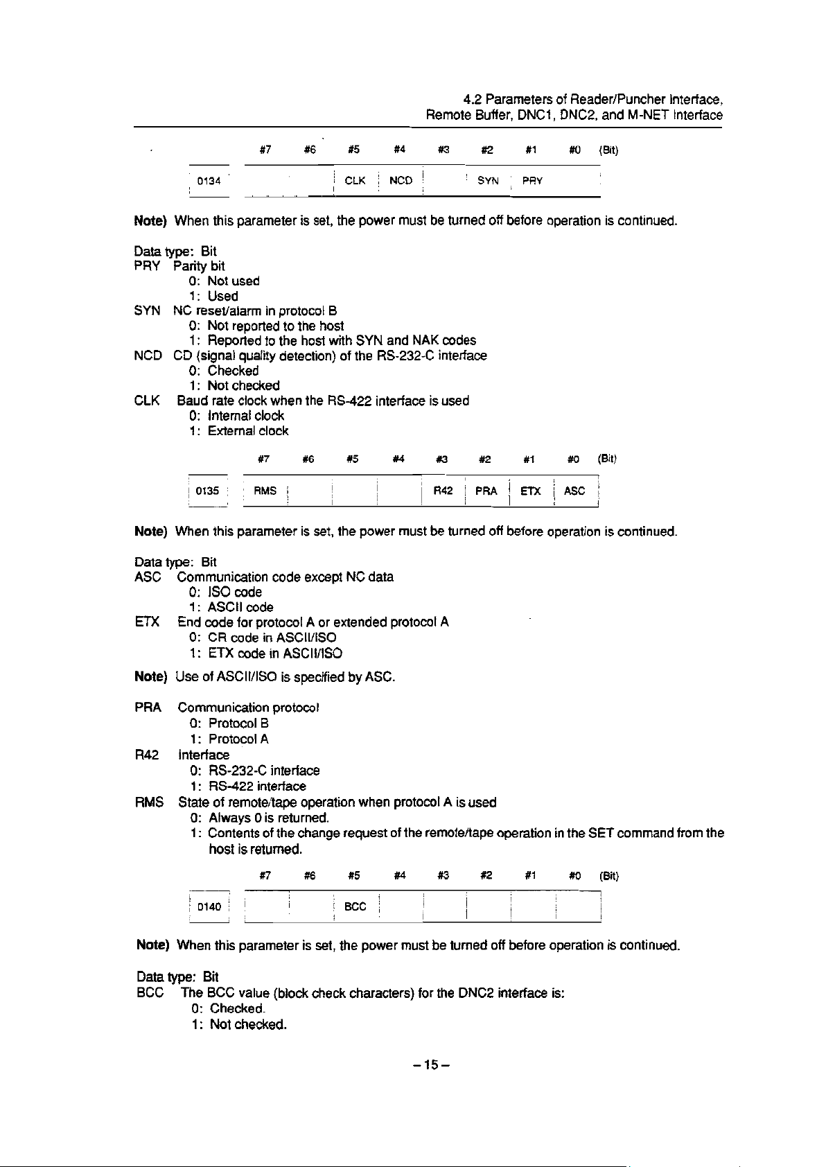
4.2 Parameters of Reader/Puncher Interface,
Remote Buffer, DNCl, DNC2, and M-NET Interface
.
!0134! j
I
I
#7
#6
t5
1 CLK j NCD !
I
X4 #3 #2
I
’ SYN ; PRY
#l
,
#O (Bit)
:
Note) When this parameter is set, the power must be turned off before operation is continued.
Data type: Bit
PRY Parity bit
0: Not used
1: Used
SYN NC reset/alarm in protocol B
0: Not reported to the host
1: Reported to the host with SYN and NAK codes
NCD CD (signal quality detection) of the RS-232-C interface
0: Checked
1: Not checked
CLK
Baud rate clock when the RS-422 interface is used
0: Internal clock
1: External clock
i
#7 #6
.
/
0135 ; i RMS j
I ;
I
#5
i
i
#4 #3 ##2
i
1
/ R42 [ PRA j ETX 1 ASC ;
i I
#l
#0
(B t)
1
t
I
1
Note) When this parameter is set, the power must be turned off before operation is continued.
Data type: Bit
ASC Communication code except NC data
0: IS0 code
1: ASCII code
ETX End code for protocol A or extended protocol A
0: CR code in ASCII/IS0
1: ETX code in ASCII/IS0
Note) Use of ASCII/IS0 is specified by ASC.
PRA Communication protocol
0: Protocol B
1: Protocol A
R42 Interface
0: RS-232-C interface
1: RS-422 interface
RMS State of remote/tape operation when protocol A is used
0: Always 0 is returned.
1: Contents of the change request of the remote/tape operation in the SET command from the
host is returned.
#2 #1 #O (Bit)
1
i
I
I
I
)
i
1
!
1
1
I
!
I
i
1 0140 j I
I ,
I
I 1
#7
I I
#6
\
I
I
#5
8
j BCC j
##4 #3
i
I
!
j
Note) When this parameter is set, the power must be turned off before operation is continued.
Data type: Bit
BCC
The BCC value (block check characters) for the DNC2 interface is:
0: Checked.
1: Not checked.
-15-
Page 21
4.2 Parameters of Reader/Puncher interface,
Remote Buffer, DNCI , DNC2, and M-NET Interface
i
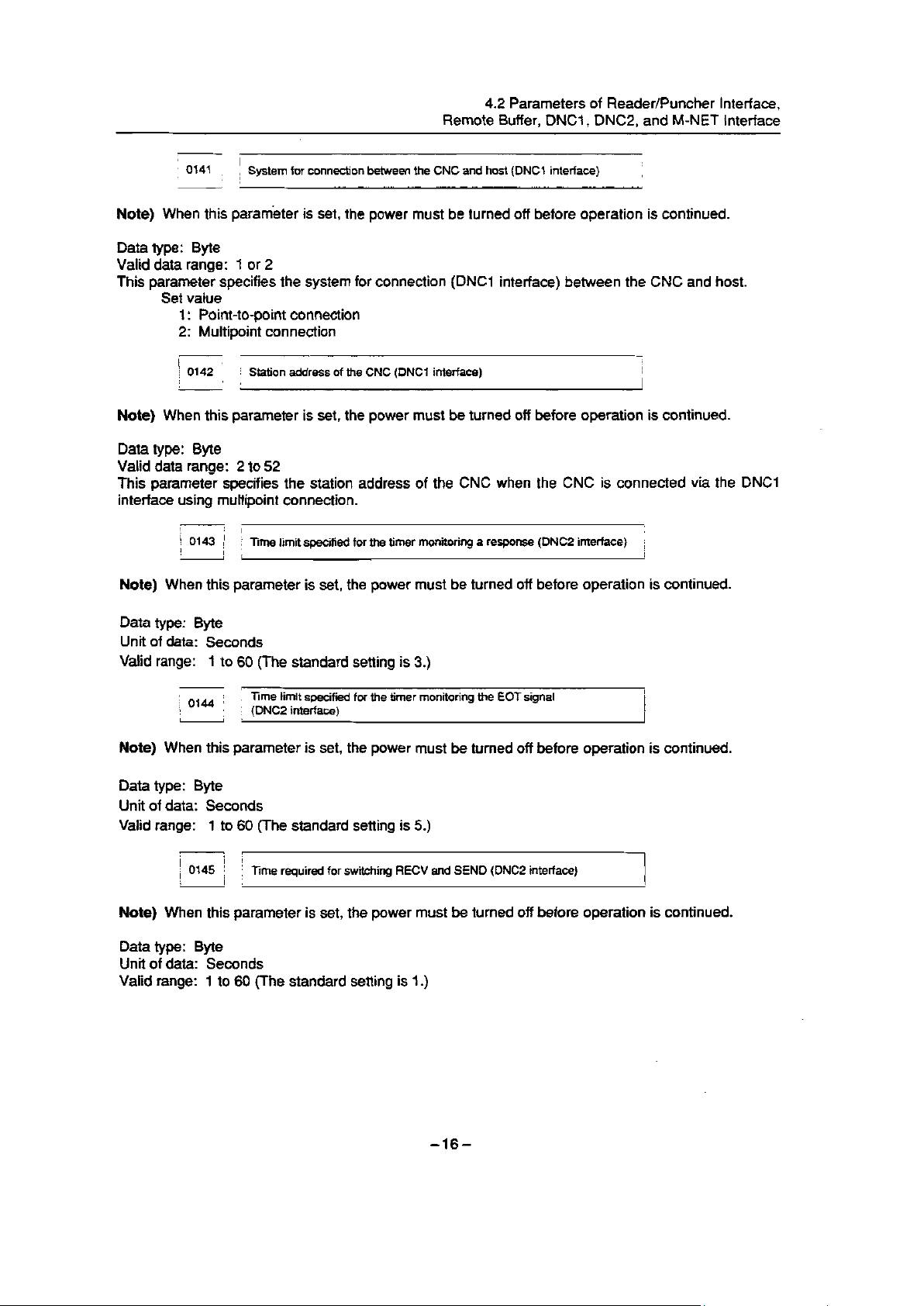
; 0141 ;
L
/ System for connection between the CNC and host (DNCl interface)
I
I
I
I
Note) When this parameter is set, the power must be turned off before operation is continued.
Data type: Byte
Valid data range: 1 or 2
This parameter specifies the system for connection (DNCI interface) between the CNC and host.
Set value
I : Point-to-point connection
2: Multipoint connection
I i
I
i 0142 i ; Station address of the CNC (DNCl interface)
, I!
Note) When this parameter is set, the power must be turned off
before operation is continued.
Data type: Byte
Valid data range: 2 to 52
This parameter specifies the station address of the CNC when
the CNC is connected via the DNCI
interface using multipoint connection.
I
0143 ; 1 j
/
I
I
3me limit specified for the timer monitoring a response (DNC2 interface)
ji
I
/
i
Note) When this parameter is set, the power must be turned off before operation is continued.
Data type: Byte
Unit of data: Seconds
Valid range:
Note) When this
1 to 60 (The standard setting is 3.)
j ;
i 0144 ;
j Time limit specified for the timer monitoring the EOT signal
: (DNC2 interface)
parameter is set, the power must be turned off before operation is continued.
Data type: Byte
Unit of data: Seconds
Valid range:
1 to 60 (The standard setting is 5.)
d r
,
i i
i
i 0145 i
i
(
lime required for switching RECV and SEND (DNC2 interface)
] ;
Note) When this parameter is set, the power must be turned off before operation is continued.
Data type: Byte
Unit of data: Seconds
Valid range: 1 to 60 (The standard setting is 1.)
-16-
Page 22
4.2 Parameters of Reader/Puncher Interface,
Remote Buffer, DNCI, DNC2, and M-NET Interface
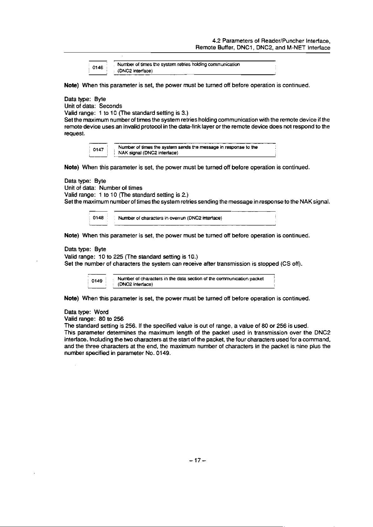
io,&: j
i
I
Number of times the system retries holding communication
(DNC2 interface)
1 :
Note) When this parameter is set, the power must be turned off before operation is continued.
Data type: Byte
Unit of data: Seconds
Valid range: 1 to 10 (The standard setting is 3.)
Set the maximum number of times the system retries holding communication with the remote device if the
remote device uses an invaiid protocol in the data-link layer or the remote device does not respond to the
request.
-
0147 j
/
I
; I!
: ! Number of times the system sends the message in response to the
NAK signal (DNC2 interface)
i
]
Note) When this parameter is set, the power must be turned off before operation is continued.
Data type: Byte
Unit of data: Number of times
Valid range: 1 to IO (The standard setting is 2.)
Set the maximum number of times the system retries sending the message in response to the NAK signal.
1
;
I
,
: Number of characters in overrun (DNC2 interface)
1
Note) When this parameter is set, the power must be turned off before operation is continued.
Data type: Byte
Valid range: 10 to 225 (The standard setting is IO.)
Set the number of characters the system can receive after transmission is stopped (CS off).
I
0149 /
i
1 1 ;
j
Number of characters in the data section of the communication packet
(DNC2 interface)
‘
1
i
.
Note) When this parameter is set, the power must be turned off before operation is continued.
Data type: Word
Valid range: 80 to 256
The standard setting is 256. If the specified value is out of range, a value of 80 or 256 is used.
This parameter determines the maximum length of the packet used in transmission over the DNC2
interface. including the two characters at the start of the packet, the four characters used for a command,
and the three characters at the end, the maximum number of characters in the packet is nine plus the
number specified in parameter No. 0149.
Page 23
Page 24
Page 25
Page 26
Page 27
Page 28
Page 29
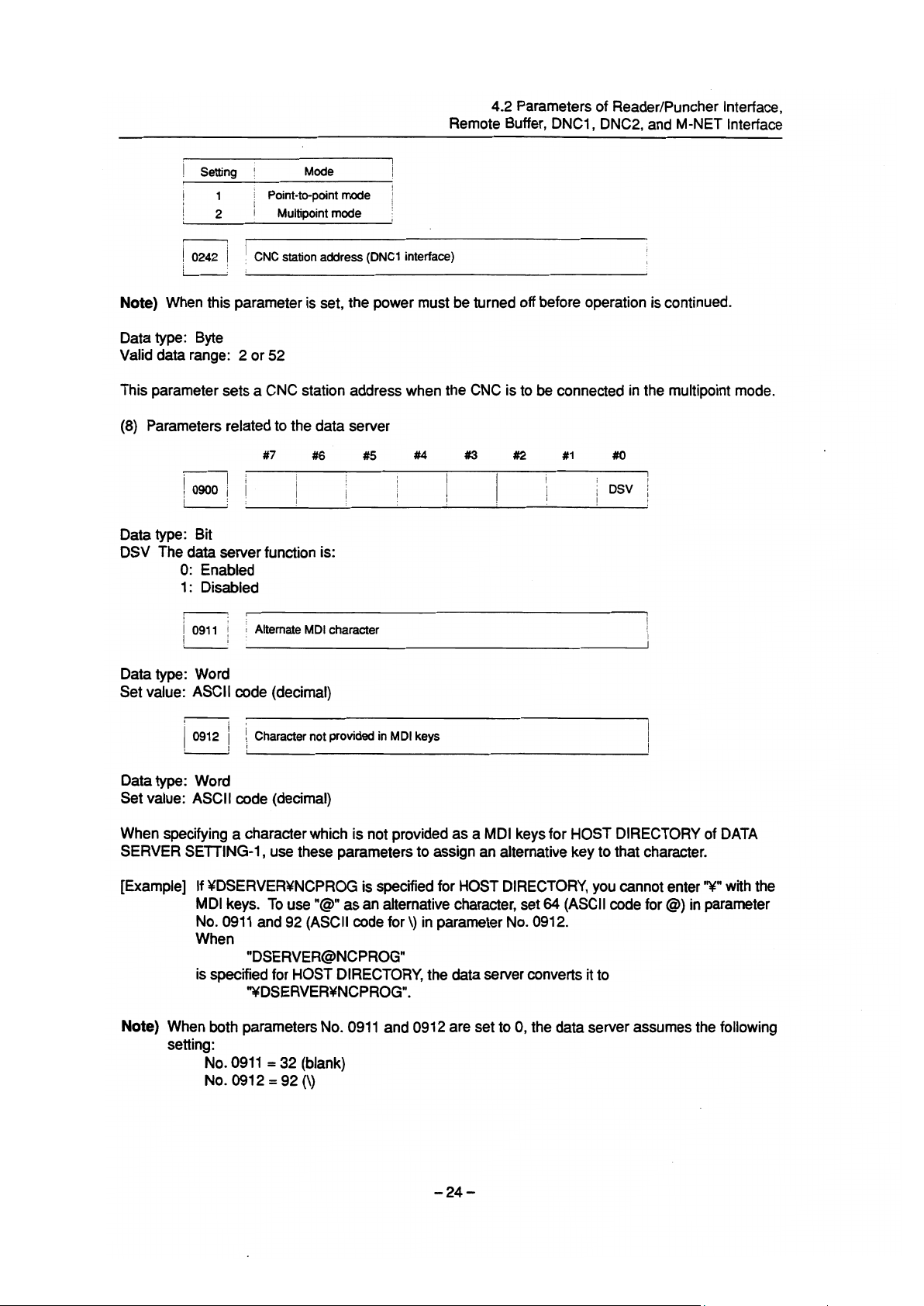
Page 30
Page 31

Page 32

Page 33

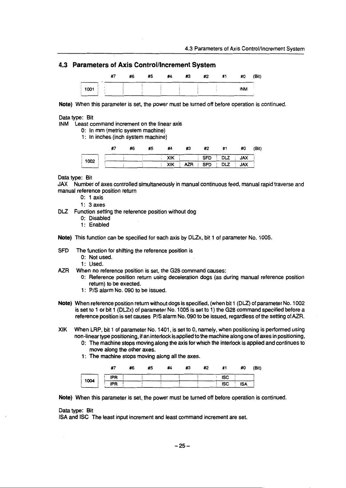
4.3 Parameters of Axis Control/increment System
DIAx Either a diameter or radius is set to be used for specifying the amount of travel on each axis.
0: Radius
1: Diameter
ZMIx The direction of reference position return and the direction of initial backlash at power-on
0: Positive direction
1: Negative direction
#7
#6 #5
#4 #3 ##2 #1
Data type: Bit axis
RAAx When an absolute command is specified for a rotation axis:
0: The end point coordinates and direction of rotation conform to bit 1 (RABx) of parameter No.
1008.
1: The end point coordinates conform to the absolute value of the value specifed in the command.
The rotational direction conforms to the sign of the value specified
Note) This parameter is valid when the rotary axis control function is provided and the rotation axis
rollover function is applied (bit 0 (ROAx) of parameter No. 1008 is set to 1).
#?
#6
#5
##4 #3 ##2
#O
in the command.
#1 #O
,-
Note) When this parameter is set, the power must be turned off before operation is continued.
Data type: Bit axis
The roll-over function of a rotation axis is
ROAX
0: Invalid
1: Valid
Note)
ROAx specifies the function only for a rotation axis (for which ROTx, #0 of parameter No. 1006,
issettol)
In the absolute commands, the axis rotates
RABx
in the direction
0: In which the distance to the target is shorter.
1: Specified by the sign of command value.
RABx is valid only when ROAx is 1.
Note)
Relative coordinates are
RRLx
0: Not rounded by the amount of the shift per one rotation
1: Rounded by the amount of the shift per one rotation
Note 1) RRLx is valid only when ROAx is 1.
Note 2) Assign the amount of the shift per one rotation in parameter No. 1260.
I
I
10091 j
i
’ I
,
#7
#6
I n
I I 1
#5
#4
1
I
RAAx The rotation direction of a rotation axis and end point coordinates in the absolute command mode:
0: Agree with the setting of bit 1 (RABx) of parameter No. 1008.
1: Agree with the absolute value of the specified value for the end point coordinates and the sign
of the specified value for the rotation direction.
#I3 #2 #1 #o
I
RAAx !
i *
I
I
i
Note) This parameter is enabled when the rotary axis control function is provided and the rotation axis
roll-over function is used (with bit
0 (ROAx) of parameter No. 1008 set to 1).
-280
Page 34

4.3 Parameters of Axis Control/Increment System
i
1010 /
Number of CNC-controlled axes
j
Note) When this parameter is set, the power must be turned off before operation is continued.
Data type: Byte
Valid data range:
1,2,3, . . . . the number of controlled axes
Set the maximum number of axes that can be controlled by the CNC.
[Example] Suppose that the first axis is the X axis, and the second and subsequent axes are the Y, Z,
A, B, and C axes in that order, and that they are controlled as follows:
X, Y, Z, and A axes: Controlled by the CNC and PMC
B and C axes: Controlled by the PMC
Then set this parameter to 4 (the 4th axis: A axis).
v
f
i 1020 *
I
I
! Name of the axis used for programming for each axis
1.
Data type: Byte axis
Set the name of the program axis for each control axis, with one of the values listed in the following table:
Note 1)
I Axis name 1 Set value
,
I
x i
Y 89 j V i 86 i
,
L
2 : 90
j Axis name / Set value i Axisname
88 ; u i 85 i A 65 1
j W ; 87 1 C 67
In the T series, when G code system A is used, neither U, V, nor W can be used as an axis name.
B
Set value
66 1
1
1
Only when G code system B or C is used, U, V, and W can be used as axis names.
Note 2)
Note 3)
The same axis name cannot be assigned to more than one axis.
When the secondary miscellaneous function is provided, address B cannot be used as an axis
name. In the T series, when CCR, ##4 of parameter 3405, is set to 1, addresses A and C may
not be used with functions, chamfering, corner R, and direct input of drawing dimensions.
Y I
I 1
I
j1022i :
I
I :
I
Setting of each axis in the basic coordinate system
I
!
1
Note) When this parameter is set, the power must be turned off before operation is continued.
Data type: Byte axis
To determine the following planes
used for circular interpolation, cutter compensation C (for the M series),
tool nose radius compensation (for the T series), etc., each control axis is set to one of the basic three axes
X, Y, and Z, or an axis parallel to the X, Y, or Z axis.
G17: Plane Xp-Yp
Gi 8: Plane Zp-Xp
G19: Plane Yp-Zp
Only one axis can be set for each of the three basic axes X, Y, and Z, but two or more parallel axes can
be set.
-290
Page 35

4.3 Parameters of Axis Control/Increment System
Meaning
axes nor a parallel axis
1
I
I
1
I
I
i
/
T I
j
i 1023
,
I ’
*
Set value i
j Neither the basic three
0
1 ! X axis of the basic three axes
i
2 ! Y axis of the basic three axes
I
3
5
6 I 1 Axis parallel to the Y axis
7
I
1
Number of the servo axis for each axis
axis of the basic three axes
! 2
Axis parallel to the X axis
i
j Axis paraDeI to the 2 axis
Note) When this parameter is set, power must be turned off before operation is continued.
Data type: Byte axis
Valid data range: 1,2,3, . . . . number of control axes
Set the servo axis number for each control axis.
Usually set the same number as the control axis number.
The control axis number is the order number that is used for setting the axis-type parameters or axis-type
machine signals.
-3o-
Page 36

(Example 1) In case of 1 path control
(a) Main CPU board max. 4 axes + Additional board
(I) Parameter No. 1023 X 1
Y 2
z 3
C 4
U 5
V
W
6
7
A 8
Main CPU board
Control axis
number
ProgElMXiSWYE
(Set by parameter No. 1020) (Set by parameter No. 1023)
4.3 Parameters of Axis ControUncrement System
Servo axis
number
1
1
2 Y
3
4
- Additional axis board
5
6
7
8 A
I
X
Z
C
U
v -
W
L
’ JVI/JSl
1
>
JVUJS2
>
1
2
.
v JV3/JS3
3
>
motor
7
t
I
-X
*
-Y
-Z
I .
I
JV4/JS4 4
>
1 .
-C
I
I .
v
JVI /JV5/JSl 5
?
>
I
l JVUJVGjJS2 6
c
*
-U
-V
4
I
JV3/JV7/JS3 7
>
c
I
I
JV4/JV8/JS4 8 A
>
I
I
-W
A
-A
-31.
Page 37

4.3 Parameters of Axis Control/Increment System
(II) Parameter No. 1023
- Main CPU board ~-1
Control axis
number
1
I
Program axis name
(Set by parameter No. 1020)
1
X
X
Y
Z
C
U
V
W
A
(Set by parameter No. 1023)
7 ’
\
*
.
JVl /JSl 1
I ,
JV2/JS2
I
I
t JV3IJS3
1 ’
l JV4WS4 4
’
L
Sewo axis number
2
3
motor
w
1
+
.
1
-X
-U
.
-Y
f
-Z
- Additional axis board
W
V
A
X
’ - JVINVSIJSI 5
l
I
JV2lJV6/JS2 6
I
I
’ - JV3IJV7IJS3 7
I
’ ’ JV4NV8/JS4 8
I
I ’
,
&
w
.
-C
,
-V
.
-A
-W
-320
Page 38

4.3 Parameters of Axis Control/increment System
(b) Main CPU board max. 6 axes + Additional board
(I) Parameter No. 1023 X
- Main
ControI axis
number
I
X
Y
z
C
U
V
Additional axis board
7 W
8
A
Y ) 2
z 3
C
U 5
V 6
>
>
>
>
l
1
4
(Set by parameter No. 1023)
I JS1
h
4
I
JS2 2 .
4
I
JS3 3
I
JS4
I
I
I ’ JS6 6
I
I
,
L .
JVI /JV5/JSl 7
’
l JV2lJV6/JS2 8
I
Sew0 axis number
1
4
motor
*
L *
t
-X
-Y
-2
‘- c
U
-V
.
l
-W
I
-A
-330
Page 39

4.3 Parameters of Axis Control/Increment System
(II) Parameter No. 1023 X
- Main CPU board
Contrul axis
number
I
1 X
2
3
4
5 U
6
(Set by parameter No. 1020)
1
Y
Z
C
V
Y
Z
C 5
U
V 6
W
A
1
3
4
2
8
7
Servo axis number
(Set by parameter No. 1023)
motor
.
1
I
.
4
-X
-U
-Y
-Z
-C
-V
>
>
I
I 4
v
I ,
v
I
L
I
’ ’ JS6
I
JSI
JS2
I
I
JS3
v JS4
JS5
.
i
A
1
2
3
4
5
6
Page 40

4.3 Parameters of Axis Control/increment System
(Example 2) In case of 2 path control
(a) Main CPU board max. 4 axes + Sub CPU board max. 4 axes
(I) Parameter No. 1023
Xl 1
Yl
Zl
Cl
- Main CPU board
Control axis Programaxisname
number
I
1
2
(Set by parameter No. 1020)
I
X
Y
3 Z
4 C
- Sub CPU board
X
Y -
3
Z
4 C
Path
1
2
3 22
4
1
JVI /JSl
>
I
I
JWJS2
>
+
. JV3/JS3
>
I
I
.
9 JV4lJS4
>
1 ,
?
>
*
I
c
>
&
l
JVl /JV5/JSl 5
I ,
JWJS6/JS2 6
A .
I
JV3IJWJS3 7
l t
’ 4 JV4lJS8fJS4 8
Path 2
x2
Y2
c2
Servo axis number
5
6
7
8
(Set by parameter No. 1023)
-1
1
motor
c
.
2
.
3
4
.
l
l
- Xl
1
- YI
- Zl
*
1
-
TX2
*
-
$
-Z2
- c2
Cl
Y2
-35-
Page 41

4.3 Parameters of Axis ControVincrement System
(II) Parameter No. 1023
- Main CPU board
Control axis
number (Set by pararwter No. 1020)
1
2
3
4
-
Sub CPU board g61
Path 1 Path 2
Xl
YI 3
Zl
Cl
X
Y
Z
C
X
Y
1 x2
2 22
4
>
.
’ 4 JWJS2 2
x ; ’ :I
I
>
I
1
I
t
Y2 7
c2
Serva axis number
(Set by parameter No. 1023)
JVllJSl
.
JV3/JS3
JV4/JS4
JWJV5lJSl 5
JWJS6IJS2 6
r
5
6
a
4
1
3
4
motor
L
1
t
.
!
\
.
*
*
-
- Zl
,
- Yl
.
- Cl
-
*
-22
Xl
x2
Z
C
x
JV3/JS?lJS3 7
-
Y2
?
JV4/JS8/JS4 8
I
c
- c2
-360
Page 42

4.3 Parameters of Axis Control/Increment System
(b) Main CPU board max. 6 axes + Sub CPU board max. 6 axes
(I) Parameter
No. 1023 Path 1
.
- Main CPU board
Control axis
number
1
2
3
4
(Set by parameter No. 1020)
X
Y
z
C
5 U
6
V
- Sub CPU board ‘1
1
X
2 Y
3
4
z
C
Xl 1
Yl 2
21 3
Cl 4
Ul 5
Vl
Path 2
X2 7
Y2
22
8
9
c2 IO
u2
6
v2 12
Servo axis number
(Set by parameter No. 1023)
11
4
’ 8 JSl 1
\
I
JS2
1
’ 4 JS3 3
I )
\
JS4
L
v
I
JS5
l
v
’ JS6 6
I
I
JSI
*
c
, A
JS2 8
JS3
+
.
I
JS4 10
2
4
5
7
9
motor
c .
, .
t
c
t
h
-
Xl
- Yl
+
- 21
.
- Cl
- Ul
- VI
-X2
-
Y2
-22
.
-
c2
71e.
5
U
6 V
I 1 JS5
I
I
-370
.
1 JS6
11
12
c
4
u2
-
.
,
v2
-
.
Page 43

Page 44

Page 45

4.4 Parameters of Coordinates
G50 When the CNC has commands G54 to G59 specifying workpiece coordinate systems (optional
function), if the G50 command for setting a coordinate system (or the G92 command in G command
system B or C) is specified,
0: The G50 (dr G92) command is executed without an alarm.
1: P/S alarm No. 010 is issued and the G50 (or G92) command is not executed.
Local coordinate system is
RLC
0: Not cancelled by reset
1: Canceled by reset
112201 I
; 11
External workpiece zero point offset value
A
Data type: 2-word axis
Unit of data:
input increment
j Linear axis (input in mm)
i Linear axis (input in inches)
Rotation axis
j IS-A i IS-B j IS-C j Unit j
j 0.01 j 0.001 i 0.0001 i mm i
f 0.001 i 0.0001 1 0.09001 i inch
1 0.01 j 0.001 : 0.0~1 : da !
j
Valid data range: -7999 to 7999
This is one of the parameters that give the position of the origin of workpiece coordinate system (G54 to
G59). It gives an offset of the workpiece origin common to ail workpiece coordinate systems.
In general,
the offset varies depending on the workpiece coordinate systems. The value can be set from the PMC
using the external data input function.
_i
t
i
I
I
I
I
,
;
I
,
I
)
m ’
i 1221 ;
I
:
/
lzzz I
t L
r
1
1223 j
;
1 PP ---I
,
1 I’
P24! !(G57)
; 1
; ’
/ 1225 [
I
I
1 1226 /
I
Workpiece zero point offset value in workpiece coordinate system 1
; WV
I
8
1
Workpiece zero point offset value in workpiece coordinate system 2 I
i 1 (G55)
,
j Workpiece zero point offset value in workpiece coordinate system 3 i
--
; ] GW
Workpiece zero point offset value in workpiece coordinate system 4
)
---
1
I
Workpiece zero point offset value in workpiece coordinate system?
] (GW
!
_-
I
I
I
1 Workpiece zero point offset value in workpiece coordinate system 6
: 1 (G59)
;- ---
--
--P-P
--e---. -- ._- _ ____
----_ --_ _-J
_-.,.-w-J
--
--..__-- ___.
Data type: 2-word axis
Unit of data:
Input increment
i Linear axis (input in mm)
--
! Linear axis (input in inches)
rEotation axis
--
i IS-A : IS-B ;
0.01 i 0.001 i 0.9001 j mm i
/
t 0.001 :
j
0.01
-_---__ -- ----
O.oool I o.oooo1~ xii-j
-----_-i
: 0.001 1 0.0091 f deg i
.--------
IS-C
: Unit ;
_ ---
Valid data range: -99999999 to 99999999
The workpiece zero point offset values in workpiece coordinate systems 1 to 6 (G54 to G59) are set.
-40s
Page 46

Workpiece coordinate
system 1 (G54)
>
\
Zero position of a machine cwrdiiate system
Fig. 4.4 Workpiece Zero Point Offset
4.4 Parameters of Coordinates
A
Workpiece coordinate
system 2 (G55)
>
i
t
I
/
i
1
i
0
1241 ’
1242 ’
_
i 1243 ;
Coordinate value of the reference position on each axis in the machine
:
coordinate system
I
Coordinate value of the second reference position on each axis in the 1
machine coordinate system
’
Coordinate value of the third reference position on each axis in the machine )
:
coordinate system
Coordinate value of the fourth reference position on each axis in the ;
machine coordinate system
Data type: 2-word axis
Unit of data
Increment system I
Millimeter machine
e Inch machine
I Rotation axis
&A I IS-8 f IS-C ;
~ -I----
: 0.01
i 0.001
i 0.01
i 0.001
! 0.0001 1 0~00001~ inch 1
1 0.001 i 0.0001 \ deg i
i 0.0001 ! mm i
1
Unit j
Valid data range: -99999999 to 99999999
Set the coordinate values of the reference positions in the machine coordinate system.
,
i :
p2444 i ;
I
:
Coodinates of the floating reference position for each axis
1
1
I
Data type: 2-word axis
Unit of data:
-41.
Page 47

4.4 Parameters of Coordinates
Increment svstem
I Millimeter machine
’ inch machine f 0.001 I 0.0001 i 0.00001 ! inch !
i Rotation
axis
1 IS-A 1 IS-B i IS-C I Unit !
i 0.01
j 0.01
0.001 j 0.0001 mm i
i
i 0.001 i 0.0001 ! dw 7
Valid data range: -99999999 to 99999999
This parameter specifies the coordinates of the floating reference position for each axis. The parameter
is automatically set when the floating reference position is specified using soft keys on the current position
display screen.
j
11250i i
I
1
i
Coordinate value of the reference position used when automatic coordinate
l system setting is performed
(
Data type: 2-word axis
Unit of data
I
Increment system
/ Linear axis (input in mm)
! Linear axis (input in inches)
Rotation axis
f
1
IS-A / IS-B i IS-C ! Unit i
;
0.01 j 0.001 1 0.0001 j mm
! 0.001 [ 0.0001 1 0.000011 inch
i 0.01
1 0.001 / 0.0001 ; deg ]
Valid data range: -99999999 to 99999999
Set the coordinate value of the reference position on each axis to be used for setting a coordinate system
automatically.
1
I
i
1251 j
!
i Coordinate
value of the reference position on each axis used for setting a
[ coordinate system automatically when input is performed in inches
i
i
Data type: 2-word axis
Unit of data .
Increment system
! Linear axis (input in inches)
j IS-A i IS-B 1 IS-C i Unit i
1 0.001 i 0.0001 j 0.00001 i inch 1
Valid data range: -99999999 to 99999999
Set the coordinate value of the reference position on each axis to be used for setting a coordinate system
automatically when input is performed in inches.
Note) This parameter is valid when ZPI in parameter 1201 #I is set to I.
Amount of a shift per one rotation of a rotation axis
Note) After setting the parameter, turn off the power once and turn it on again to operate the machine.
Data type: 2-word axis
Unit of data
-420
Page 48

4.4 Parameters of Coordinates
i Standard value i
: 36000
j 360000
1 3600000
Valid data range:
Set the amount of
i
increment system ! Unit of data
I
i
1
1000
IS-A i 0.01 deg
IS-B j 0.001 deg
IS-C : 0.0001 deg
to 9999999
a shift per one rotation of a rotation axis.
j Distance between two oooosite tool posts in mirror image
Data type: 2-word
Unit of data:
Increment system / IS-A ! IS-B j IS-C ’
f Miliimeter machine
1 Inch machine
j 0.01 ) 0.001 i
I
:
0.001 1 0.0001
Valid data range: 0 to 99999999
Set the distance between two opposite tool posts in mirror image.
1
I
:
0.0001
o.00001 i
f
Unit
1 mm i
inch I
1
i
j
-439
Page 49

Parameters of Stroke Limit
4.5
4.5 Parameters of Stroke Limit
#7
#6 #5
I
BFA ’ LZR 1 RL3
I
#4 #3 #2 #1
I
1 LMS j
I
I
##O i
i
i OUT 1
I
(B t)
I
I
J
Data type: Bit
OUT The area inside or outside of the stored stroke limit 2 is set as an inhibition area.
0: Inside
1: Outside
LMS The EXLM signal for switching stored stroke limit 1
0: Disabled
1:
Enabled
RL
Stored stroke limit 3 release signal RLSOT3 is
0: Disabled
1: Enabled
LZR Checking of stored stroke limit 1 during the time from power-on to the manual position
reference return
0: The stroke limit 1 is checked.
1: The stroke limit 1 is not checked
BFA When a command that exceeds a stored stroke limit is issued
,
0: An alarm is generated after the stroke limit is exceeded.
1: An alarm is generated before the stroke limit is exceeded.
Note) When an absolute position detector is used and a reference position is already set upon power-
up, stored stroke limit check I is started immediately after power-up, regardless of the setting.
(Bit)
3
,
I
/ 1301
L
, 1
1
I ’
i
#7 #6
1
PLC 1
#5
i
#4 #I3 #2 #l 80
NPC (
I
,
I
I
I
I
I
1
I
I
I
!
Data type: Bit
NPC As part of the stroke limit check performed before movement, the movement specified in G31 (skip)
and G37 (automatic tool length measurement (for M series) or automatic tool compensation (for
T series)) blocks is:
0: Checked
1: Not checked
PLC Stroke limit check before movement is:
0: Not performed
1: Performed
#7 #6 #5
I
I
I
!
#4 ##3 #2 #I
I
!
i
]
I
i oT3x i onx
I
I
#IO i
OT2x
i
(BV
Data type: Bit axis
OT2x Whether stored stroke limit 2 is checked for each axis is set.
0: Stored stroke limit 2 is not checked.
1: Stored stroke limit 2 is checked.
OT3x Whether stored stroke limit 3 is checked for each axis is set.
0: Stored stroke limit 3 is not checked.
1: Stored stroke limit 3 is checked.
Page 50

4.5 Parameters of Stroke Limit
1
i 13201
i
1
I
1 1321 i
I
,-
Coordinate value
;=is
,L
j
’
i Coordinate value
each axis
I of stored stroke limit 1 in the positive direction on each
1 of stored stroke limit 1 in the negative direction on
i
[
I *
Data type: 2-word axis
Unit of data:
I
Increment svstem
I Millimeter machine i 0.01
!
; Inch machine i 0.001
Rotation axis ’ 0.01
I
f 0.001 ! 0.0001 : mm 1
I
j 0.0001 ; 0.00001
0.001 j 0.ooo1 ’ deg i
/
Unit 1
inch /
+
Valid data range: -99999999 to 99999999
The coordinate values of stored stroke limits I in the positive and negative directions are set for each axis
in the machine coordinate system. The outside area of the two limits set in the parameters is inhibited.
Note 1)
Note 2)
For axes with diameter specification, a diameter value must be set.
When the parameters are set as follows, the stroke becomes infinite:
parameter 1320. < parameter 1321
For movement along the axis for which infinite stroke is set, only incremental commands are
available.
If an absolute command is issued for this axis, the absolute register may overflow,
and normal movement will not result.
7
I
: .
/ 1322 i
1
;
/-) Ls
Coordinate value of stored stroke limit 2 in the positive direction on each
axis
Coordinate value of stored stroke limit 2 in the negative direction on each
’
A
7
’
1 ,
Data type: 2-word axis
Unit of data:
Increment system
i Millimeter machine
I Inch machine
; Rotation axis
/ IS-A 1 IS-B j IS-C f Unit 1
1
i 0.01
! O-001 / 0.00Ol j 0.00001 : inch i
; 0.01 i 0.001 [
f 0.001 j 0.0001 i mm i
0.0001 ; &g i
‘(
I
Valid data range: -99999999 to 99999999
Set the coordinate values of stored stroke limits 2 in the positive and negative directions for each axis in
the machine coordinate system. OUT, #O of parameter 1300, sets either the area outside or the area
inside specified by two limits as the inhibition area.
Note) For axes with diameter specification, a diameter value must be set.
I
/ 1324 i
I
i
i 1325 j i Coordinate value of stored stroke limit 3 in the negative direction on each axis
L I I
I
I
Coordinate value of stored stroke limit 3 in the positive direction on each axis
1
I
I
I *
J
,
I
Data type: 2-word axis
Unit of data:
-45-
Page 51

4.5 Parameters of Stroke Limit
I
Increment system
j Millimeter machine
! Inch machine i 0.001 1 0.0001 i 0.00001 j inch 1
I
Rotation axis
i
i IS-A ; IS-B i IS-C i Unit !
! 0.01
I
/ 0.001 0.0001 j mm
I
I 0.01 I i 0.001 i 0.0001 ! deg :
j
Valid data range: -99999999 to 99999999
Set the coordinate values of stored stroke limits 3 in the positive and negative directions for each axis in
the machine coordinate system. The area inside the limits set in the parameters is inhibited.
Coordinate value II of stored stroke limit 1 in the positive direction on each
/ f
Coordinate value Ii of stored stroke limit 1 in the negative direction on each i
i
I
,
1
Data type: 2-word axis
Unit of data:
Valid data range:
I
Increment svstem
; Millimeter machine
j Inch machine
i Rotation
axis
-99999999 to 99999999
! IS-A ! IS-B 1 IS-C i Unit !
I 0.01 I 0.001 I 0.0001 j mm i
0.001 i 0.0001 1 0.00001
0.01 f 0.001 1 0.0001
f I
inch
1 / deg /
!
Set the coordinate values of stored stroke limits 1 in the positive and negative directions for each axis in
the machine coordinate system.
When stroke limit switching signal EXLM is ON, stroke limits are checked with parameters 1326 and 1327,
not with parameters 1320 and 1321. The area outside that set by parameters 1326 and 1327 is inhibited.
Note) The EXLM signal is enabled only when LMS, #2 of parameter 1300, is set to 1.
-460
Page 52

4.6 Parameters of the Chuck and
4.6 Parameters of the Chuck and Tailstock Barrier (160TB)
i Profile of a chuck
Data type: Byte
Vaiid range: 0 or 1
0: Chuck which holds a workpiece on the inner surface
1: Chuck which holds a workpiece on the outer surface
Tailstock Barrier
(16.TB)
/
-
, 1333 /
I
i
11334: !
!
i
/1335j
i Dimensionsoftheclawofachuck(L)
I ’
I
c
jrnxnsof claw of a chuck (W)
! Dimensions
I i
Dimensions of the part of a claw at which a workpiece is held (W 1)
of the part of a claw at which a workpiece is held (Ll )
1
1 f
X coordinate of a chuck (CX)
f
L J !
[ ;
1 ,336
I
1 2 coordinate of a chuck (CZ)
.
i L
Data type: Two words
Unit of data:
Increment system
i Millimeter machine i 0.001 i 0.0001 i mm j
Inch machine
Valid range: No. 1331 to No. 1334: 0 to 99999999
No. 1335 to No. 1336: -99999999 to 99999999
Specify the profile of a chuck.
i 0.0001 j 0.00001 j inch 1
I
#
1
,
1
!
I
I
1
-479
Page 53

4.6 Parameters of the Chuck and
Tailstock Barrier (I 6-TB)
Chuck which holds a workpiece on the outer surface m=l )
Y
L A
A
I+
W
V
-L
Ll +
Wl
x
A
cx
Zero point of the
workpiece
coodinate system
n
! Symbol 1 Description
j TY 1
[
j
I
i cz i Z coordinate of a chuck
I
:
,
i
i
t
i Wl
Profile of a chuck (0: Chuck which holds a workpiece on the inner surface,
Chuck which holds a workpiece on the outer surface)
1 1:
cx
I X coordinate of a chuck
L ! Dimensions of the claw of a chuck
w
I Dimensions of the claw of a chuck (radius input)
Ll
I Dimensions of the part of a claw at which a workpiece is held
I
Dimensions of the par-t of a claw at which a workoiece is held (radius in;DutI i
!
Chuck which holds a workpiece on the inner surface (Ty=O)
Y
I
A’ T
,
w - 1
4 ” .
L
WI
( Ll 1
X
)r
h
A
cx
i
,
I
!
I
i
!
I
i
1
i
/
!
TY: Specifies the profile of a chuck. When TY is set to 0, the chuck holding a workpiece on the inner
surface is specified. When TY is set to 1, the chuck holding a workpiece on the outer surface is
specified. The profile of the chuck is assumed to be symmetrical with respect to the z-axis.
CX, and CZ : Specify the position (point A) of a chuck with the coordinates of the workpiece coordinate
system. In this case, do not use the coordinates of the machine coordinate system.
Note) Specifying the coordinates with a diameter or radius depends on whether the corresponding axis
conforms to diameter or radius specification . When the axis conforms to diameter specification,
specify the coordinates with a diameter.
L, Ll, W, and WI : Define the profile of a chuck.
Note) Always specify W and WI with radiuses. Specify Land L1 with radiuses when the Z-axis conforms
to radius specification.
Page 54

4.6 Parameters of the Chuck and
Tailstock Barrier (16.TB)
1
1
1,342; ;
I
I Length of a tailstock (L)
j ;
I .
I :
1’
I I
i j
/1343i !
I
1 / Diameter of a tailstock (01)
113441
1
i
I
I
T i Diameter of a tailstock (02)
1346 / i
I
1347
I
1
113481
i
1
/
L
: Length of a tailstock (L2)
I
! :
I
6 I
1 i
/ i
I I
r
7
j
/
i
I
; 8
Data type: Two words
Unit of data:
Diameter of a tailstock (0)
Length of a tailstock (Ll )
Diameter of the hole of a taiktock (03)
2 coordinate of a tailstock (TZ)
I
/
I
I
I
6
1
I
I
I
I
I
I
Increment svstem f IS-B i
i Millimeter machine
j Inch machine
Valid
range: No. 1341 to No. 1347
No. 1348
Specify the profile of a tailstock.
IS-C 1
i 0.001 I o.oooi i mm I
I 0.0001 j o.oooo1 i
: 0 to 99999999
: -99999999 to 99999999
Unit t
inch i
Page 55

4.6 Parameters of the Chuck and
Tailstock Barrier (I 6-TBI
X
T
Zero point
workpiece
system
Tz
: Specifies the position (point B) of a tailstock with the Z-axis coordinate of the workpiece
coordinate system.
of the
coordinate
I
[ Symbol 1
I
i lz 1 ; Z-axis coordinate of a tailstook
jL
,
j
I Ll : Lenclth of a tailstock (1)
: Dl
! I2 I
:. 02
j D3
I
Length of a tailstock
D 1
Diameter of a tailstock (diameter input)
Diameter of a tailstock (1) (diameter inrW
Lenoth of a tailstock (2)
0 Diameter of a tailstock (2) (diameter input)
: Diameter of the hole of a tailstock (diameter input)
In this case, do not use the coordinate of the machine coordinate system.
Description
V
1
I
I
j
The profile of a taiistock is assumed to be symmetrical with respect to the Z-axis.
Note) Specifying the position of a tailstock with a radius or diameter depends on whether the Z-axis
conforme to radius or diameter specification.
L2, D, Dl , D2, and 03 :
L L1,
Define the profile of a tailstock.
Note)
Always specify D, Dl , D2, and 03 with diameters. Specify L, Ll , and L2 with radiuses if the Z-axis
conforms to radius specification.
-5O-
Page 56

4.7 Parameters of Feedrate
4.7 Parameters of Feedrate
: ;
! 1401 / 1
; I;_
#7 #6 #5 #4
i RDR i TDR
i RDR I TDR RF0 4
RF0
#3 #2 #1
JZR
LRP RPD
LRP
#0 i
t RPD ,
.--_
(B t)
Data type: Bit
RPD Manual rapid traverse during the period from power-on time to the completion of the reference
position return.
0: Disabled (Manual continuous feed is performed.)
1: Enabled
LRP Positioning (GOO)
0: Positioning is performed with non-linear type positioning so that the tool moves along each
axis independently at rapid traverse.
1: Positioning is performed with linear interpolation so that the tool moves in a straight line.
JZR The manual reference position return at continuous manual feedrate
0: Not performed
1: Performed
RF0 When cutting feedrate override is 0% during rapid traverse,
0: The machine tool does not stop moving.
1: The machine tool stops moving.
TDR Dry run during threading or tapping (tapping cycle G74 or G84; rigid tapping)
0: Enabled
1: Disabled
RDR Dry run for rapid traverse command
0: Disabled
1: Enabled
#7 #6 85
,‘ ;--- :
I
11402; L-- ; :
8 .
I
- -___-
##4
I
1
i JRV
1
#3 #2
j OV2 j FeA i i 1
,
’
OV2 1 F8A 1
#I
#O (Bit)
1
I !
<For T series>
F8A Valid data range for an F command in feed-per-minute mode
0: Range specified with bit 0 (MIF) of parameter No. 1403
1: 7
;
I
i
I
Increment system
Metric input
Inch input i inch/min j
Rotation axiS 1 deg/min
;
Units j
f
mm/min ; 0.001 - 240000. j 0.001 - 100000. I
IS-A, IS-B j IS-C
/
0.00001 - 9600. I / 0.00001 -4000. i
! 1 - 240000. 1 I-looooo. 1
1
I
I
<For M series>
F8A Valid data range for an F command with a decimal point in feed-per-minute mode
.
0 I
. I
I
;
i
_~_ _
i
r- ~~
.
1 ; .
,
Increment system /
Metric input
Inch input
Rotation axis (mm)
Rotation axis (inch)
Increment system j Units I
Metric input
Inch input ,
Rotation axis
Units 1 IS-A, IS-B j IS-C
:
; mm/min i
i inch/min j
[ deg/min 1
degimin 1 I-9600. j
i
1 mmfmin f
i
inch/min [
j deg/min 1 1 - 240000. ; I - 1ooooo. 1
0.001 - 99999.999
0.00001 - 999.99999
I- 240000.
IS-A, IS-B /
0.001 - 240000. j 0.001 - 100000. !
o.oooo1- 9600. I 0.00001 -
( 1-100000. j
I-4000. j
IS-C
4ooo. i
1
I
!
I
I
i
I
-51.
Page 57

4.7 Parameters of Feedrate
Data type:
Bit
0V2 2nd feedrate override is
0: specified every 1%
1: specified every 0.01%
Signals used for 2nd feedrate override are:
Note)
l AFVO to AFV7 (GO13) when OV2 = 0
*APFOQ to
l AFPl5 (G094, G095) when 0V2 = 1
JRV Manual continuous feed (jog feed)
0: Jog feed is performed at feed per minute.
1: Jog feed is
Specify a feedrate in parameter No. 1423.
Note)
I 1
I
I ; R~I i
’ 1403
I
1 ;
Note)
When this parameter is set, the power must be turned off before operation is continued.
Data type: Bit
MlF Cutting feedrates at feed per minute is specified by F commands
0: In units of 1 mm/min for millimeter machines or 0.01 inches/min for inch machines.
1: In unit of 0.001 mm/min for millimeter machines or 0.00001 inches/min for inch machines.
performed at feed per rotation.
#7
#6
I
I I
#5
i
j
i
#4 #3 #2 #l #O i
I
j
I
I
i
I
i MIF
(Bt)
1
I
Note) M series are not equipped with this parameter. Cutting feedrates are specified by F commands in
units of 0.001 mm/min for millimeter machines or 0.00001 inches/min for inch machines.
RTV Override while the tool is retracting in threading
0: Override is effective.
1: Override is not effective.
,
#7 #6
I
i
i
#5 #4 #3
I I
1
i
I
I
i
;
Data type: Bit
HFC The feedrate for helical cutting is:
0: Clamped so that the feedrates along an arc and linear axis do not exceed the maximum
cutting feedrate specified by parameter.
1: Clamped so that the composite feedrate along an arc and linear axis does not exceed the
maximum cutting feedrate specified by parameter.
DLF After a reference position is set, manual reference position return is performed at:
0: Rapid traverse rate (parameter No. 1420).
1: Manual rapid traverse rate (parameter No. 1424)
This parameter selects a feedrate for reference position return performed without dogs. This
Note)
parameter also selects a feedrate when manual reference position return is performed according
to bit 7 (SJZ) of parameter No. 0002
using rapid traverse without deceleration dogs after a
reference position is set.
#2 #1
I
I
!
f
#O (Bit)
DLF 1 HFC
j
I
i DLF j HFC
-52-
Page 58

4.7 Parameters of Feedrate
; 1410
I
1 Dry run
I
rate/Manual continuous feed rate (at linear feed and circular feed)
:
Data type: Word
Unit of data:
Valid data range:
Increment system i Unit of data
j Millimeter machine
: Inch machine
i Vaiid data range
i
IS-A, IS-B : IS-C
:
f 1 mm/min 6-15000 1 642000 i
! 0.1 inch/min
! 6-6000 : 6-4800 I
1
Set the dry run rate when the jog feedrate is overridden by 100%.
Specify the jog feedrate when the override is 100% for manual linear or circular interpolation.
r-7
t
1411 I !
1 1;
;
Cutting feedrate in the automatic mode at power-on
I
I
I
Setting entry is acceptable.
Data type: Word
Unit of data: j .
Valid data range: 1
j Millimeter machine
; Inch machine
Increment system i Unit of data j
1
1 1 mrn/min
f 0.01 inch/min 1
’ Validdatarange 1
1 IS-A, IS-B : G-C j
I
0
6 - 32767
I
When the machine requires little change in cutting feedrate during cutting, a cutting feedrate can be
specified in the parameter. This eliminates the need to specify a cutting feedrate in the NC command data.
I 1
t
I
; 1414 j
I
I 6
Feedrate for reverse movement
i
i
I
I
I
This parameter sets the feedrate for reverse movement when the retrace function
is used.
(1) For rapid traverse
Unit of data, valid data range:
i
Valid data range
/
,s A ,s B ,s c
-
( - : -
L
1
i
6-240000 i 6-100000 j
1
increment system
I
: Miikneter machine
: Inch machine
i Rotation axis
1
Unit of data
j
j 1 mrn/min ; &24OW& ; s-100~0 i
i 1 deg/min
Note) When 0 is set in this parameter, the rapid traverse rate that is set in parameter No. 1420 is used
for reverse movement.
(2) For cutting feed
When a value other than 0 is specified in this parameter, the same feedrate as an F command specified
using the value without a decimal point is set. When 0 is specified in this parameter, the programmed
feedrate (F command) is used for reverse movement.
-530
Page 59

4.7 Parameters of Feedrate
i
* ,
i 1420 i
I
-
i ;
1 Rapid traverse rate for each axis
!
/
Data type: 2-word axis
Unit of data: !
Valid data range i
tncrement system
,
I Millimeter machine
1 Inch machine
r
!
Rotation axis
Unit of data 1
j 1 mrn/min
0.1 inch/min
, 1
deg/min
’
Vaiid data range 1
IS-A, IS-B 1 IS-C
i
; 30-240000 ; 30-100000 j
i 30-96000 i 30-48000 !
i 30-240000 / 30-100000 1
Set the rapid traverse rate when the rapid traverse override is 100% for each axis.
j 1421 t
1
1 FO rate of rapid traverse override for each
I
i
Data type: Word axis
Unit of data:
i
Valid data range: i
: Millimeter machine
I Inch machine
’ Rotation axis
Increment system
I
I
) 1 mm/min
0.1 inch/min
i
i 1 deg/min
axis
Unit of data
i Valid data range I
’
IS-A, IS-B / IS-C
j
1 6-15000
1 6-12000 1
! 6-6000 j 64800 i
i 6-15000 1 6-12000 1
Set the FO rate of the rapid traverse override for each axis.
1 Rapid traverse override signal 1 Ovenide vdue !
ROV2 )
I
I
I
I
0
0 I
1 I
1
ROVl j
0
I
0
I 1
100 %
i
1
50 %
i
25 %
FO
i
/
FO: Parameter 1421 ,
1
j
I
1
i
1
i
1 1422
I
Maximum cutting feedrate for all axes
/
I !
Data type: 2-word
Unit of data, valid range:
Increment system
1 Millimeter machine 1 mWmin
8
Inch machine 1 0.1 inch/min I 6-96000
1
1
Unit of data
I
I
j
_~~__~~
6-240000 6-100000
1
i 6-48000
Specify the maximum cutting feedrate.
A feedrate in the tangential direction is clamped in cutting feed so that it does not exceed the feedrate
specified in this parameter.
Note) To specify the maximum cutting feedrate for each axis, use parameter No. 1430 instead.
Page 60

4.7 Parameters of Feedrate
; 1423 :
I
Feedrate in manual continuous feed (jog feed) for each axis
I
Data type: Word axis
(1) In M series, or in T series when JRV, bit 4 of parameter No. 1402, is set to 0 (feed per minute), specify
a feedrate in manual continuous feed at feed per minute with an override of 100% applied to the jog
feedrate.
Unit of data, valid range:
fncrement system
: Millimeter machine
; Inch machine
’ Rotation axis
1 1 mm/min
j
0.1 incNmin i
1 deg/min
!
I
I
1
I
6-32767
i
(2) When JRV, bit 4 of parameter No. 1402, is set to 1 (feed per revolution) in T series, specify a jog
feedrate (feed per revolution) under an override of 100%.
Unit of data, valid range:
Increment system
i Millimeter machine
: Inch machine
I Rotation axis
i Unit of data i
i 0.01 mm/rev 1
i 0.001 inch/rev
i 0.01 degkev
Valid data range 1
O-32767
9
i
/
f
I
j 1424 ;
Data type: 2-word
Unit of data:
Valid data range:
Manual rapid traverse rate for each axis
axis
Increment system
I
Millimeter machine
I
Inch machine
Rotation axis
i
I
i 1 mm/min
/ 0.1 inch/min
1 deg/min
i
Unit of data
i
Valid data range
’ Is A Is B
j
!
IS-C i
i 3~2k000 I 30-100000 i
~30-96000
i 30-48000 1
i 30-240000 i 30-100000 i
1
-I
Set the rate of manual rapid traverse when the rapid traverse override is 100% for each axis.
Note) If 0 is set, the rate set in parameter 1420 is assumed.
i
j 1425 :
1
Data type: Word
Unit of data:
Valid data range:
FL rate of the reference position return for each axis
8
axis
Increment system
i Millimeter machine
: Inch machine
; Rotation axis
j Unit of data !
I 1 mmlmin
! 0.1 inch/min
j
1 deg/min
I
Valid data range
;
IS-A, IS-B i
IS-C !
1 6-15000 i 6-12000 /
i 66000 ] 6-4600 j
i 6-15000 1 6-12000 /
/
Set a feedrate (FL rate) after deceleration when the reference position return is performed for each axis.
-55-
Page 61

4.7 Parameters of Feedrate
I
j 1426 1
I External deceleration rate of cutting feed
Data type: Word
Unit of data:
Valid data range:
Increment system Unit of data
I Millimeter machine
r
i Inch machine
I
I 1 mm/min
( 0.1 inch/min
IS-A, IS-B : IS-C i
t
I 6-15000 : 6-12000 /
i 6-6000 : 6-4800 :
Set the external deceleration rate of cutting feed.
! :
j 1427 1
,
:
Data type: Word axis
Unit of data:
Valid data rancle: !
,
1
External deceleration rate of rapid traverse for each axis
I
/
” I
1 Millimeter machine
[- Inch machine
! Rotation axis
Increment system
I
f
l Unit Of data ! &A, IS-9 1
I
1
1 mrWmin 1 6-15000
i 0.1 inch/min
i 1 deg/min
I
I
1 64000
I 6-15000 ; 6-12000 j
Set the external deceleration rate of rapid traverse for each axis
I
/ 1428 i
I
I
I
Reference position return feedrate
!
I
, 1
Valid data range
Valid data range
IS-C I
) 6-12000 1
m4800 i
1
1
i
I
,
I
I
/
,
1
4
Data type: 2-word axis
Unit of data:
Valid data range:
i
I Millimeter machine
’ Inch machine
Rotation axis
Increment system
Unit
of data 1
i
j 1 mrn/min
; 0.1 inch/min
i 1 deg/min
,
Valid data range
I IS-A, IS-B j IS-C ,
; 30-240000 i 3CHOOOOO~
1 30-96000 ; 30-48000
1
1
i 30-240000 ; 30-100000~
This parameter sets a rapid traverse rate for reference position return operation using deceleration dogs,
or for reference position return operation
before a reference position is set.
This parameter is also used to set a feedrate for the rapid traverse command (GOO) in automatic operation
before a reference position is set.
Note) This parameter is enabled when the reference position return feedrate setting function is used.
When 0 is set in this parameter, this parameter disables the reference position return feedrate
setting function.
Page 62

4.7 Parameters of Feedrate
i Before a reference position is set j After a reference position is set
I
Reference position return feedrate ; Reference position return fee&ate
i
)
I
,
Reference position return by G28
/ Rapid traverse command (GOO) in
, automatic operation
I
1
Manual reference i Without dogs ‘I
I position return
,
Manual rapid traverse
I
*
1
With/without dogs: Reference position return operation not using/using deceleration dogs
‘2
For manual rapid traverse before a reference position is set, a jog feedrate (parameter No. 1423) or
f
1 Withdogs' 1 No.'424 1
I
I
i
1
i
1
I
I
I
setting function
Disabled /
I
d
No.
1420 !
I
/
! No. 1428 :
/
,
No. 1423 or No. 14247
setting function
Enabled ’ Disabled i
1
!
I
I
; No. 1424 i
I
/
No.
No. 1420 or No. 1 42403
No. 1424
Enabled ’
1420
No.
1428
manual rapid traverse rate (parameter No. 1424) is used according to the setting of bit 0 (RPD) of parameter No. 1401.
+
3
The rapid traverse rate set in parameter No. 1424 or No. 1420 is used according to the setting of bit
1 (DLF) of parameter No. 1404 when reference position return is performed without dogs, or when
reference position return operation is performed with bit 7 (SJZ) of parameter No. 0002 set to 1 after
a reference position is set (when reference position return operation is performed using rapid traverse
without deceleration dogs).
7 I
I
I
I I
114301 ;
i ; :
Maximum cutting feedrate for each axis
,
Data type: 2-word axis
Unit of data, valid range:
I
I
Valid data range
i
I IS-A. IS-B 1 IS-C 1
1 -602kOOO
1 6-96000
i 6-100000
i 6-48000
i 6-240000 i 6-100000 j
1
’
increment system
Millimeter machine
!
j Inch machine
i Rotation axis
I
Unit of data
/
/
I
i 1 mm/min
1 0.1 inch/min
1 1 degfmin
Specify the maximum cutting feedrate for each axis.
A feedrate for each axis is clamped in cutting feed so that it does not exceed the maximum feedrate
specified for each axis.
Note 1)
This parameter’ is effective only in linear and circular interpolation. In polar coordinate,
cylindrical, and involute interpolation, the maximum feedrate for all axes specified in
parameter No. 1422 is effective.
Note 2)
If the setting for each axis is 0, the maximum feedrate specified in parameter No. 1422 is
applied to all axes and the feedrate is clamped at the maximum feedrate.
7
1 :
; 1431 / ’
i
-
’
Maximum cutting feedrate for all axes in the look-ahead control mode
I
1
1
Data type: 2-words
Unit of data, valid range:
Page 63

4.7 Parameters of Feedrate
,
1
Increment system
! Millimeter machine
I
I Inch machine
I
Rotation axis
I
Unit of data
1 1 mfn/min
-m%nch/min
I -1 deg/min
I
Valid range
1
1 IS-A. IS-8 ; IS-C i
1 O-240000 ; 0-100000 1
i 046000 i 048000 i
! O-240000 i O-100000 1
Specify the maximum cutting feedrate for all axes in the look-ahead control mode.
A feedrate in the tangential direction is clamped in cutting feed so that it does not exceed the feedrate
specified in this parameter.
Note 1)
Note 2)
To specify the maximum cutting feedrate for each axis, use parameter No. 1432 instead.
In
a mode other than the look-ahead, mode, the maximum cutting feedrate specified in
parameter No. 1422 or No. 1430 is applied and the feedrate is clamped at the maximum
feedrate.
1
i-----l 1
114321 6
Maximum cutting feedrate for each axis in the look-ahead control mode
(
I
Data type: 2-word axis
Unit of data, valid range:
Increment system
1 Millimeter machine
i Inch machine
1 Rotation axiS
Unit of da@
i lmmhnin
I 0.1 incNmin
i 1 deg/min
O-240000 i 0400ooo 1
1
! O-96000 i 048000 I
1 O-240000 j o-1ooooo I
.a
Specify the maximum cutting feedrate for each axis in the look-ahead control mode.
A feedrate for each axis is clamped during cutting feed so that it does not exceed the maximum cutting
feedrate specified for each axis.
Note 1) This parameter is effective only in linear and circular interpolation. In polar coordinate,
cylindrical, and involute interpolation, the maximum feedrate for all axes specified in parameter
No. 1431 is effective.
Note 2) If a setting for each axis is 0, the maximum feedrate specified in parameter No. 1431 is applied
to all axes and the feedrate is clamped at the maximum feedrate.
Note 3) In a mode otherthan the look-ahead mode, the maximum cutting feedrate specified in parameter
No. 1422 or No. 1430 is applied and the feedrate is clamped at the maximum feedrate.
145oj 1
: A j Changeof feedratefor onegraduation on the manual pulsegeneratorduring Fl digit feed
I
Data type: Byte
Unit of data:
Valid data range: 1 to 127
Set the constant that determines the change in feedrate as the manual pulse generator is rotated one
graduation during one-digit F code feed.
=
AF
Fmaxi
1OOn
(where, i = 1 or 2)
In the above equation, set n. That is, the number of revolutions of the manual pulse generator, required
to reach feedrate Fmaxi is obtained.
Fmaxi refers to the upper limit of the feedrate for an one-digit F code
feed command, and set it in parameter 1460 or 1461.
Fmaxi : Upper limit of the feedrate for Fl to F4 (parameter 1460)
Fmax2: Upper limit of the feedrate for F5 to F9 (parameter 1461)
-580
Page 64

; 1451 j ;
i j
I
i 1
j
i 1452
4
; !
-
j I
14
/ 53
I
! I
11 j
i1454/ !
, 1
1 \
r----l i
11455’ I
I
1 !
I
I !
/ 4571 1
1 ’ I i
I I
,
1 !
I
i1458j t
! I
1 1459,j j
1
:
Feedrate for Fl digit command
1
Feedrate for Fl digit command F2 1
1
Feedrate for Fl digit command F3
Feedtate for Fl digit command F4
Feedrate for Fl digit command F5
,
Feedrate for Fl digit command F6
Feedrate for Fl digit command F7
: Feedrate for Fl digit command F8 : ,
r
i
Feedrate for Fl digit command F9 :
Fl
4.7 Parameters of Feedrate
I
!
I
I
I
J
#
I
I
I
!
,
1
1
I
I
Input for setting is enabled.
Data type: 2-word
Unit of data: I
Valid data range: i
Increment system
i Millimeter machine
j Inch machine
1 Rotation axis 1 0.1 dWmin
Unit of data
I 0.1 mm/min
i 0.01 inch/min
i 6-150000 i 6-120000 1
i 6-60000 1 6-46000 1
1 6-150000 1 6-120000 1
Set Feedrates for one-digit F code feed commands Fl to F9.
When an one-digit F code feed command is executed, as the feedrate is changed by turning the manual
pulse generator, these parameter values also change accordingly.
y&o: /
Data type: 2-word
Unit of data:
Valid data range: i
;
Upper limit of feedrate for the one-digit F code feed command (Fl to F4)
;
Upper limit of fee&ate for the one-digit F code feed command (F5 to F9)
I
Increment system
i Millimeter machine
i
Inch machine
!
1 Rotation axis
1
Unit of data
;
I
.mm/min
1
1
! 0.1 inch/min
I
i 1 wmin 1 6-15000 j 6-12000
1 j
Valid data range
1
j IS-A, IS-Bi IS-C
1 6-15000
i 6-6000 j 6-4800
I
I 6-12000
7
,
Set the upper limit of feedrate for the one-digit F code feed command.
As the feedrate increases by turning the manual pulse generator, the feedrate is clamped when it reaches
the upper limit set. If an one-digit F code feed command Fl to F4 is executed, the upper limit is that set
in parameter 1460. If an one-digit F code feed command F5 to F9 is executed, the upper limit is that set
in parameter 1461.
-59-
Page 65

4.8 Parameters of Accelaration/Deceleration Control
4.8 Parameters of Acceleration/Deceleration Control
117 ii6 #5
1
r---I
/ 16*’ i i
Data type: Bit
OVB Block overlap in cutting feed
0: Blocks are not overlapped in cutting feed.
1: Blocks are overlapped in cutting feed.
Block overlap outputs the pulses remaining at the end of pulse distribution in a block together with
distribution pulses in the next block. This eliminates changes in feedrates between blocks.
Block overlap is enabled when blocks containing GO1 , G02, or GO3 are consecutively specified in G64
mode. If minute blocks, however, are specified consecutively, overlap may not be performed.
The following pulses in block F2 are added to the pulses remaining at the end of pulse distribution in block
Fl .
(Number of pulses to be added) = F2 x
When Fl = F2
1
........ ............ ........
............................
.... .... .... .... .... .... ....
.... .... .... .... .... .... ....
.... .... .... .... .... .... ....
........ .... .... .... .... ....
.... .... .... .... .... .... ....
.... .... .... .... .... .... ....
........ .... .... .... .... ....
.... .... .... .... .... .... ....
.... .... .... .... .... .... ....
.... .... .... .... .... .... ....
.... .... .... .... .... .... ....
.... .... .... .... .... .... ....
........ ..I. .... .... .... ....
........ .... .... .... .... ....
.... .... .... .... .... .... ....
.... .... .... .... .... .... ....
........ .... .... .... .... ....
.... ................ .... ....
.... .... .... .... .... .... ....
.... .... .... .... .... .... ....
.... .... .... .... .... .... ....
.... .... .... .... .... .... ....
............ .... ............
~
ACD ; NCI f RTO ; j
; ACD ; NCI j RTO 1
#4 #3 #2 #l ##0 i
j
i
i OVB 1
(Number of pulses required at the end of block Fl )
1
!
Fl
(B t)
I
I
t
F
. . .
. . .
. . .
. . .
. . .
. . .
. . .
. . .
. . .
. . .
. . .
. . .
. . .
. . .
. . .
. . .
. . .
. . .
. . .
I..
. . .
. . .
I..
. . .
. . .
I
When block overlap is disabled
Fl
When block overlap is enabled
-60-9
F2
Page 66

4.8 Parameters of AccelaratiorVDeceleration Control
RTO Block overlap in rapid traverse
0: Blocks are not overlapped in rapid traverse.
1: Blocks are overlapped in rapid traverse.
Note) See the description of parameter No. 1722.
inposition check at deceleration
NCI
0: Performed
1: Not performed
ACD Function for automatically reducing the feedrate at corners (automatic corner override function)
0: The function is not used.
1: The function is used.
,
I
i
’ j
(16021 I
! *
!
#7 . #6
.
,
I
/ LS2 j
I
#5 #4
i
CSD
#3 #2
i
I
j ,
I
Data type: Bit
FWB Cutting feed acceleration/deceleration before interpolation
0: Type A of acceleration/deceleration before interpolation is used.
1: Type B of acceleration/deceleration before interpolation is
Type A:
When a feedrate is to be changed by a command, acceleration/deceleration starts
after the program enters the block in which the command is specified.
Type 8:
When a feedrate is to be changed by a command, deceleration starts and terminates
at the block before the block in which the command is specified.
When afeedrate is to be changed by a command, acceleration starts after the program
enters the block in which the command is specified.
c Example of a deceleration process >
Feedrate
Point 1
T
~~~~~~~~~~~~~~~~.
F3
r-rrrrrrrrr,
t-l
7
8
t
*
- Specified
- ---- Feedrate after accelera-
tion/deceleration before
interpolation is applied
Type A
I(
8
s
\
8
\
b
\
\
\
8 I 8
8
1
\
t
\
t
fee&ate
. .
c Example of an acceleration process >
Feedrate
,
F3
#l
i
i
#O
i
1 FWB ’
I I
[
used.
-
Specified feedfate
- - - - - Feedrate after accelera-
tion/deceleration before
interpolation is applied
Nl N2
To change the feedrate from F3 to F2, it is necessary
NI N2
to start reducing the feedfate at point 1.
-61 -
Page 67

4.8 Parameters of AccelarationIDeceleration Control
CSD In the function for automatically reducing a feedrate at comers,
0: Angles are used for controlling the feedrate.
1: Differences in feedrates are used for controlling the feedrate.
LS2 Acceleration/deceleration after interpolation for cutting feed in the look-ahead control mode is:
0: Exponential acceleration/deceleration
1: Linear acceleration/deceleration. (The function for linear acceleration/deceleration after
interpolation for cutting feed is required.)
87
#6 #5
,
i
,
##4 #3 #I2 #l ##O
I I
/ JGLx j
I
/
j
I
0
4
i CTBx i CTLX ’
I
i
0
Data type: Bit axis
CTLx Acceleration/deceleration in cutting feed including feed in dry run
0: Exponential acceleration/deceleration is applied.
1: Linear acceleration/deceleration after interpolation is applied.
Note) If the optional function of linear acceleration/deceleration after interpolation in cutting feed is not
provided, exponential acceleration/deceleration is used irrespective of this setting.
To use bell-shaped acceleration/deceleration after interpolation, set this parameter to 0 and select
the acceleration/deceleration using CTBx, bit 1 of parameter No. 1601.
I
I cnx / CTLx i
I 0 1 0 Exponential acceleration/deceleration
6
Parameter
0
1
Acceleration/deceleration
1
i Linear acceleration/deceleration after interpolation
0
1 Bell-shaped acceleration/deceleration after interpolation
,
j
i
I
I
i
CTBx Acceleration/deceleration in cutting feed including feed in dry run
0: Exponential acceleration/deceleration or linear acceleration/deceleration after interpolation
is applied (depending on the setting in CTLx, bit 0 of parameter No. 1610).
1: Bell-shaped acceleration/deceleration after interpolation is applied.
Note) This parameter is effective only when the function of bell-shaped acceleration/deceleration after
interpolation in cutting feed is provided. If the function is not provided, the setting in CTLx, bit 0 of
parameter No. 1610, determines the type of acceleration/deceleration irrespective of the setting
in this parameter.
JGLx Acceleration/deceleration in manual continuous feed (jog feed)
0: Exponential acceleration/deceleration is applied.
The same acceleration/deceleration as used for cutting feed is applied (depending on which
1:
is used in cutting feed).
TimeconstantT(T1) used in linear acceleration/deceleration or bell-shaped
acceleration/deceleration in rapid traverse for each axis
1
Data type: Word axis
Unit of data: ms
Valid range: 0 to 4000
Specify a time constant used in acceleration/deceleration in rapid traverse. When the optional function of
bell-shaped acceleration/deceleration in rapid traverse is provided, bell-shaped acceleration/deceleration
is applied in rapid traverse. If the function is not provided, linear acceleration/deceleration is applied.
-620
Page 68

4.8 Parameters of AccelarationIDeceleration Control
(I) When the function is provided, set this parameter to time constant Tl used in bell-shaped
acceleration/deceleration in rapid traverse, and set parameter No. 1621 to time constant T2.
(2) When the function is not provided, specify a time constant used in linear acceleration/deceleration.
Note 1)
When parameter No. 1621 (time constant T2 used in bell-shaped acceleration/deceleration in
rapid traverse) is set to 0, linear acceleration/deceleration is applied in rapid traverse even if the
function is provided. In this case, this parameter stands for a time constant used in linear
acceleration/deceleration in rapid traverse.
c Linear acceleration/deceleration for rapid traverse r
I
,
1: Time constant for linear acceleration/deceleration
c Bell-shaped acceleration/deceleration for rapid traverse >
Speed
Rapid -
traverse
rate
T :
Tl : Time constant under linear acceleration/deceieration
T2: Time for comer rounding
Totai time = Tl + T2
Time for linear part = Tl - T2
Time for curved part = T2
Set the value when the rapid traverse rate is 1 OO?k. If it is under
I
+ +
T2
1 OO?b, the total time is reduced. (Constant acceleration method)
Set the value when the rapid traverse rate is 100%. If it is under 1 00%, the total time is reduced. (Constant
acceleration method)
The value of Tl is determined from the torque of motor. Usually set the value of T2 to 24 ms or 32 ms.
,
;
I
L
1621
i
i Time constant T2 used in bell-shaped acceleration/deceleration in rapid
j
; i
traverse for each axis
1
I
1
Data type: Word axis
Unit of data: ms
Valid range: 0 to 512
Specify time constant T2 used in bell-shaped acceleration/deceleration in rapid traverse for each axis.
Note 1)
This parameter is effective when the function of bell-shaped acceleration/deceleration in rapid
traverse is provided. Set parameter No. 1620 to time constant Tl used in bell-shaped
acceleration/deceleration in rapid traverse, and set this parameter to time constant T2.
For details of time constants Tl and T2, see the description of parameter No. 1620.
Note 2)
When this parameter is set to 0, linear acceleration/deceleration is applied
in rapid traverse. The
setting in parameter No. 1620 is used as a time constant in linear acceleration/deceleration.
-630
Page 69

4.8 Parameters of Accelaration/Deceieration Control
Time constant of exponential acceleration/deceleration or bell-shaped accel- 1
eration/deceleration after interpolation, or linear acceleration/deceleration i
after
interpolation in cutting feed for each axis
I
I
Data type: Word axis
Unit of data: ms
Valid data range: 0 to 4000
Set the time constant used for exponential acceleration/deceleration, bell-shaped acceleration/decelera-
tion after interpolation, or linear acceleration/deceleration after interpolation in cutting feed for each axis.
Except for special applications, the same time constant must be set for all axes in this parameter.
time constants set for the axes differ from each other, proper straight lines and arcs cannot be obtained.
If the
Bell-shaped acceleration/deceleration after cutting
l Time
I
/ 1623 ;
I
+
b
T
f
FL rate of exponential acceleration/deceleration in cutting feed for each axis
1
I 1
feed interpolation
1: Total time. It is constant irrespective of feed rate. (Time
constant is constant).
The curve corresponds to that Tl = T/2 and T2 = T/2 set in
parameter no. 1620 and 1621.
1
Data type: Word axis
Unit of data:
Valid data range: j
;
Increment system j Unit of data
i Millimeter machine
t Inch machine
/ Rotation axis
I
I 1 mrn/min
i 0.1 inch/min
) 1 deg/min
i
’
Valid data range
i
IS-A, IS-B
IS-C
1
1 6-15000 j 6-12000 1
/ 6-6000 t 6-4800 1
1 6-15000 1 6-12000 /
Set the lower limit (FL rate) of exponential acceleration/deceleration in cutting feed for each axis. Except
for special applications, this parameter must be set to 0 for all axes.
If a value other than 0 is specified,
proper straight lines and arcs cannot be obtained.
I
I ;
! 1624
Time constant of exponential acceleration/deceleration or bell-shaped
i
; acceleration/deceleration or linear acceleration/deceleration after interpola-
’ i
I
, ; tion,
in jog feed for each axis.
Data type: Word axis
Unit of data: ms
Valid data range: 0 to 4000
Set the time constant used for exponential acceleration/deceleration, bell-shaped acceleration/decelera-
tion or linear acceleration/deceleration after interpolation in jog feed for each axis.
I
/1625/ ’
1 I
’
FL rate of
exponential acceleration/deceleration in jog feed for each axis
,
_
Data type: Word axis
Unit of data:
Valid data range:
Page 70

4.8 Parameters of Accelaration/Deceleration Control
Increment system Unit of data
! Millimeter machine
1 Inch machine
Rotation axis
I 1 mm/min
1 0.1 incNmin
I 1 deg/min
: Valid
’
: 6-15000 8 642000 i
Is A Is B
9 -
6-6000
645000
data range /
* IS-C :
6-4800
- 642000 8
i
Set the lower limit (FL rate) of exponential acceleration/deceleration in jog feed for each axis.
] Time constant of exponential acceleration/deceleration in the thread cutting
’ cycle for each axis
:
Data type: Word
Unit of data: ms
Valid data range: 0 to 4000
Set the time constant used for exponential acceleration/deceleration in the thread cutting cycle (G76, G78
(G92 in G code system A)) for each axis.
5
’ 1 ; FL rate of exponential acceleration/deceleration in the thread cutting cycle
I I
I
: e
j 16271 ;
for each axis
I
: :
I
Data type: Word axis
i
Unit of data:
Valid data range: t
Increment system
:
Millimeter machine
j Inch machine
: Rotation axis
i Unit of data ’
!
! 1 mm/min
f 0.1 inch/min
i 1 deg/min
Valid data range ’
IS-A, IS-B i IS-C
1
i 6-15000 j 6-12000
f 6-6000
1 6-15000
j 6-4800 !
I 6-12000 (
Set the lower limit (FL rate) of exponential acceleration/deceleration in the thread cutting cycle (G76, G78
(G92 in G code system A)) for each axis.
7:
/1mo ;
’
:
Parameter 1 for setting an acceleration for pre-interpolation linear accelera-
tion/deceleration (maximum machining speed during pre-interpolation lin-
: ear acceleration/deceleration)
j
1
I
Data type: 2-word
Unit of data, valid range:
I I
I
Increment system
I
’ Millimeter machine
: Inch machine
[ Unit of data 1
i 1 mm/min
j 0.1 inch/min
I
Valid range
1 IS-A, IS-B !
IS-C
j 6-240000 1 O-160-600 1
; 6-96000 ! o-48000 f
This parameter is used to set an acceleration for linear acceleration/deceleration before interpolation. In
this parameter, set a maximum machining speed during linear acceleration/deceleration before interpo-
lation. In parameter No. 1631, set a time used to reach the maximum machining speed.
-65
Page 71

4.8 Parameters of Accefaration/Deceleration Control
Note 1)
Parameter 1: Parameter No.
Parameter 1
Parameter 2
Parameter 2: Parameter No. 1631
Time
When 0 is set in parameter No. 1630 or parameter No. 1631, linear acceleration/deceleration
1630
before interpolation is disabled.
Note 2)
In the look-ahead control mode, parameter No. 1770 and parameter No. 1771 are valid.
7 I Parameter 2 for setting an acceleraiion for linear acceleration/deceleration ’
’ :
1 1 before interpolation (time used to reach the maximum machining speed
1631 ’
I
; !,
during linear acceteration/deceleration before interpolation.)
1
Data type: Word
Unit of data: 1 ms
Valid range: 0 to 4000
This parameter is used to set an acceleration for linear acceleration/deceleration before interpolation.
this parameter, set the time (time constant) used to reach the speed set in parameter No. 1630.
Note 1) When 0 is set in parameter No. 1630 or parameter No. 1631, linear acceleration/deceleration
before interpolation is disabled.
Note 2) In parameter Nos. 1630 and 1631, set values that satisfy the following:
Parameter No. 1630/Parameter No. 1631 > 5
Note 3) In the look-ahead control mode, parameter No. 1770 and parameter No. 1771 are valid.
,
1 ;
I ,
/ 1710 ; j
f ;
I
1
Minimum deceleration ratio (MDR) of the inner circular cutting rate in
automatic comer override
!
1
I
I
I
In
Data type: Byte
Unit of data: %
Valid data range: 1 to 100
Set the minimum deceleration ratio (MDR) in changing the inner circular cutting feed rate by automatic
comer override.
In
circular cutting with an inward offset, the actual feedrate for a specified feedrate (F) becomes as follows:
F x Rc (Rc :
RP
1 Rp :
\
Radius of the path of the cutter’s center
Programmed radius
\
1
I
/
By the actual feedrate becomes the value obtained from the above equation, the specified rate F can be
achieved on the program path.
-660
Page 72

Fig. 4.8 (a) Rp and Rc
If Rc is too small in comparison with Rp so that
deceleration ratio (MDR) is set.
When @ + 0,
RP
The actual rate becomes as follows:
F x (MDR)
!
/I714 1
I ,
, Angle (0~) to recognize the inner
4.8 Parameters of AccelaratiorVDeceieration Control
Programmed path
RC
- + 0, the cutter will stop. To prevent this, the minimum
RP
comer in automatic override
Data type: Byte
Unit of data: Degree
Valid data range: 1 to 179 (standard value = 91)
Set the angle to recognize the inner corner when automatic override is performed for the inner corner
! 1712 j
, Ankunt of automatic override for an inner comer
Data type: Byte
Unit of data: %
Valid data range:
Set the amount of
1 to 100 (standard value = 50)
automatic override for an inner corner.
------ ---
I Distance Le from the starting point in inner comer automatic override
--___ _----_----.
I
Data type: Word
Unit of data:
Unit
_..-_-
1
Valid data range:
7
! Increment svstem i
1
in mm i Yl ! 0.1 / 0.01 1 mm j
Input
Input in inches 1 0.1 I 0.01 1 0.001 ! inch _I
f
~ _ _~
0
to 3999
I
IS-A f IS-B i IS-C !
Set distance Le from the starting point in an inner corner for automatic corner override.
-670
Page 73

4.8 Parameters of Accelaration/Deceleration Control
-
j Distance Ls up to the ending point in inner corner automatic override :
Data type: Word
Unit of data:
i Increment system (
j Input in mm 11
i Input in inches
j 0.1 i 0.01
IS-A i Is-8 i IS-C j
I 0.1
1 0.01 j mm
Unit I
Valid data range: 0 to 3999
Set distance Ls up to the end point in an inner corner for automatic corner override.
If 8 c 8p, the inside of a comer is recognized. = ( 0p is set in parameter 1711.)
When an inner corner is recognized, the feedrate is overridden in the range of Le in the block immediately
before the intersection of the corner and Ls in the next block following the intersection.
Ls and Le are each a straight line connecting the intersection of the corner and a given point on the path
of the cutter’s center.
Ls and Le are set in parameters 1713 and 1714.
Y
ti Programmed
. a
* .
#
.
.
An override is applied from point a to b.
.
.
.
.
.
*‘,’ Cutter center path
.
path
Fig. 4.8 (b) Distance Le and Ls in the automatic corner override at an inner corner
I 1
I
1
1 1722 /
/ #!
1 L
I Rapid
traverse feedrate reduction ratio for overlapping rapid traverse blocks
Data type: Byte axis
Unit of data: %
Valid range: 0 to 100
This parameter is used when rapid traverse blocks are arranged successively, or when a rapid traverse
block is followed by a block that does not cause movement. When the feedrate for each axis of a block
is reduced to the ratio set in this parameter, the execution of the next block is started.
1
i
f
I
-680
Page 74

Example:
4.8 Parameters of Acceiaration/Deceleration Control
X-axis feedrate
rh
Nl GOOX--; N2GOOX--;
A
Fh
Fh: Rapid traverse feedrate
a
: Setting of parameter No. 1722 (feedrate reduction ratio)
Fd: Feedrate where deceleration is terminated:
When the function of overlapping rapid
traverse blocks is enabled
Wh’en the function of overlapping rapid
traverse blocks is disabled
Fh x a/l00
Note) The parameter No. 1722 is effective when parameter No. 1601 #4 (RTO) is set to 1.
I
/ i
I 1730 i 1 Maximum feedrate for arc radius R
] ;!
!
I
1
I
Data type: Word
Unit of data, valid range:
i Millimeter machine
l Inch machine
I 1 mm/min
) 0.1 inch/min
1 8-15000
t 8-6000
i 042000 I
:
O-4800 i
Set a maximum feedrate for the arc radius set in parameter No. 1731. Set this parameter when the arc
radius-based feedrate clamping function is enabled.
7 I
i 1731 1 ; Arc radius value corresponding to a maximum feedrate
e ,
I ;
1
1
I
I
Data type: 2-word
Unit of data:
,
1 Linear axis (millimeter machine) i
t Linear axis (inch machine)
L
Unit
i IS-A 1 IS-8 i IS-C 1 Unit !
0.01
1 0.001 I 0.0001
1 0.001 i O.OOOl [ 0.0OOO~nch ]
i ~~
1 mm 1
Valid range: 1000 to 99999999
Set the arc radius corresponding to the maximum feedrate set in parameter No. 1730. Set this parameter
when the arc radius-based feedrate clamping function is enabled.
i
i
’ 1732 \
I I
i Minimum value (RVmin) for arc radius-based feedrate clamp
Data type: Word
Unit of data, valid
range:
Increment system Unit of data
1 Millimeter machine
i Inch machine I 0.1 incNmin
I 1 mmlmin
Valid range
7
IS-A, IS-8 ;
,
IS-C
i 0-15000 ! o-t2000 I
I O-6000 i o-4800 !
-690
Page 75

4.8 Parameters of Accelaration/Deceleration Control
The arc radius-based feedrate clamping function reduces the maximum feedrate as the arc radius
decreases. When the specified maximum feedrate is not greater than RVmin (minimum value for arc
radius-based feedrate clamping), RVmin is used as the maximum feedrate.
1740 j
Data type: 2-word
Unit of data: 0.001 deg
Valid range: 0 to 180000
Set a critical angle to be subtended by two blocks for corner deceleration when the angle-based automatic
comer deceleration function is used.
The angle subtended by two blocks is defined as 8 in the examples shown below.
GB(Gol)
Angle subtended by two straight lines
i
1741 i ’
,
I
Data type: Word axis
Unit of data, valid range:
; Critical angle subtended by two blocks for automatic corner deceleration
A (GO1 )
Block
Block B (GOl)
Angle subtended by an arc and its tangent
1 ! Feedrate for assuming the termination of automatic comer deceleration (for ;
1 1
acceleration/deceleration after interpolation)
I
increment system
1 Millimeter machine
! inch machine
:
Rotation axis
/ Unit of data i
I
j 1 mrWmin
i 0.1 inch/min
i 1 deg/min
Valid range i
1
IS-A, IS-B j
! 6-15000 ! 6-12000 1
! 6-6000
1 6-15000 j 6-12000 i
is-c t
i 6-4800 i
8
>
I
I
Set the feedrate for assuming the termination of deceleration in automatic corner deceleration.
11762
I j
Data type: Word axis
Unit of data: 1 ms
Valid range: 0 to 4000
Set an exponential acceleration/deceleration time constant for cutting feed in the advanced control mode.
’ Exponential acceleration/deceleration time constant for cutting feed in the look- 1
;
ahead control mode
-7o-
3
Page 76

7
‘1
/ 1763 : 1
I
,
i Minimum speed in exponential aecekration/deceleration for cutting feed in the
look-ahead control mode
i
:
,
Data type: Word axis
Unit of data, valid range:
4.8 Parameters of AccelaratiorVDeceleration Control
j
1
Increment system
i Millimeter machine
i inch machine
I
Rotation axis
I
i Unit of data
i 1 mm/min
1 0.1 inch/min
i 1 deg/min
Valid range 1
i Is A Is B
, - :
IS-C j
1 6-15000 6-12000 j
!
i 6-6000
64800 i
; 6-15ooO , 6-12000 j
Set a minimum speed (FL) in exponential acceleration/deceleration for cutting feed in the look-ahead
control mode
i
I
f 1768 ,
Data type: Word
i Time constant for linear acceleration/deceleration during cutting feed in look-
/
ahead control mode.
axis
j
I
Unit of data: ms
Valid range: 8 to
512
This parameter sets a time constant for linear acceleration/deceleration for cutting feed in the look-ahead
control mode.
Note) The function for linear acceleration/deceleration after interpolation for cutting feed is required.
I
i
I
j 1770 ;
I
] Parameter 1 (for look-ahead control) for setting an acceleration for linear accelera-
tion/deceieration before interpolation (maximum machining speed during linear
;
i ! i acce)eration/deceleration before interpolation)
/
J
Data type: 2-word
Unit of data, valid range:
I
increment system
i Millimeter machine
I
i Inch machine 1
Valid range
Unit of data
!
1 1 mm/min
0.1 inch/min i ( 6-96000 i 648000
r
IS-A, IS-B j
6-240000 i 6-100000
/
1
I
IS-C I
I
i
1
This parameter is used to set an acceleration for linear acceleration/deceleration before interpolation in
the look-ahead control mode. In this parameter, set the maximum machining speed during linear
acceleration/deceleration before interpolation. Set the time used to reach the maximum machining speed
in parameter No. 1771.
Parameter 1
(No. 1?70)
Time
Parameter 2 (No. 1771)
Note) When 0 is set in parameter No. 1770 or parameter No. 1771, linear acceleration/deceleration
before interpolation is disabled.
-71-
Page 77

4.8 Parameters of Accelaration/Deceleration Control
! 1 Parameter 2 (for look-ahead contrrrttfpr setting an acceleration for linear accelera- I
;
1771 j
i
tion/deceletation before interpolation (time used to reach the maximum machining
I : speed during linear acceleration/deceleration before interpolation)
i
I
!
Data type: Word
Unit of data: 1 msec
Valid range: 0 to 4000
This parameter is used to set an acceleration for linear acceleration/deceleration before interpolation
in
the look-ahead control mode. In this parameter, set the time (time constant) used to reach the speed set
in parameter No. 1770.
Note 1)
When 0 is set in parameter No. 1770 or parameter No. 1771, linear acceleration/deceleration
before interpolation is disabled.
Note 2)
In parameter Nos. 1770 and 1771, set values that satisfy the following:
Parameter No. 1770/Parameter No. 1771 g 5
pq
If761 /
I
/
I
1 (Must not be used)
I !
f
! 1
j Minimum speed for the automatic comer deceleration function (look-ahead
/ :
control)
1
(Must not be used)
!
I
9
!
I
I
j
j
Data type: Word axis
Unit of data, valid range:
Increment system
j Millimeter machine
! Inch machine
Rotation axis
j
i
Unit Of data
: 1 mm/min
j 0.1 inch/min
i 1 dec/min
1
Valid range
/ IS-A, IS-B ;
1 6-15000
IS-C j
j 6-12000 i
i 6-6000 i 6-4600 1
i 6-15000
i 6-12000 1
Set a speed at which the number of buffered pulses in deceleration is assumed to be 0 when
linear acceleration/deceleration before interpolation is used.
t
I
!
/
’ 778 /
i Minimum speed for the automatic comer deceleration function (for linear i
j
acceleration/deceleration before interpolation)
1 1
i
I
1
Data type: Word axis
Unit of data, valid range:
1
i Millimeter machine
! Inch machine
i Rotation axis
’
Increment system
Unit of data
i 1 mm/min
! 0.1 inch/min
I 1 deg/min
Valid range
i
1
IS-A, IS-B i
IS-C i
i 645000 j 642000 1
j 6-6000 i 6-4800 1
i 645000 i 642006 (
I
j
Set a speed at which the number of buffered pulses in deceleration is assumed to be 0 when
linear acceleration/deceleration before interpolation is used.
-720
Page 78

4.8 Parameters of Accelaration/Deceieration Control
i
/
17791 ’
I
i
Critical angle subtended by twobiocksfor automatic comer deceleration (for look- I
ahead control)
t
Data type: 2-word
Unit of data: 0.001 deg
Valid range: 0 to 180000
Set a critical angle to be subtended by two blocks for corner deceleration when the angle-based automatic
corner deceleration function is used.
The angle subtended by two blocks is defined as 8 in the examples shown
below.
, e
>
,
Angle subtended by two straight lines Angle subtended by an arc and its tangent
1780/
i
1 I /
I
Data type: Word
Unit of data, valid range:
Block B (GOl)
,
1 Allowable speed difference for the speed difference-based comer deceleration !
function (for iinear acceleration/deceleration before interpoiation)
;
Increment system
i Miliimeter machine
1
Inch machine
Unit of data t
1 1 mm/min ] 6-15000 1 6-12000
I 0.1 inch/min 1 . 6-6000 f 64800
Valid range j
i IS-A, IS-B ! IS-C j
1
j
Set the speed difference for the speed difference-based automatic corner deceleration function when
linear acceleration/deceleration before interpolation is used.
I
/ 1781 ;
( Allowable speed difference for the speed difference-based comer deceteration
1 t 1 function (linear acceierationkkeleration after interpolation)
Data type: Word axis
Unit of data, valid range:
,
Increment system
1 Millimeter machine
I
j Inch machine
! Rotation axis
Unit of data
i 1 mm/min
; 0.1 incWmin
; 1 deg/min
I
Valid range
IS-A. IS-B i IS-C j
1 6-15000 i 642000 1
I
/
6-6000
1
6-15000 i 642000 /
1
1 6-4800
I
Set a speed difference for the speed difference-based automatic corner deceleration function whenlinear
acceleration/deceleration after interpolation is used.
-730
Page 79

4.8 Parameters of Acceiaration/Deceieration Control
1
; 1783 :
I
Allowable speed difference forlMsyeed difference based comer
function (linear acceleration/deceleration before interpolation)
I
deceleration
l
[
Data type: Word axis
Unit of data, valid range:
Increment system
j Millimeter machine
! Inch machine
i Rotation axis
I
Unit of data
1
1
i 1 mm/min
f 0.1 inch/min
[ 1 deg/min
Valid range
1
I
IS-A, IS-B !
1 6-1500(3 1 6-12000 f
1 6-6000
i 6-15000
i 6-4800 j
i 6-12000 j
!
IS-C !
A separate allowable feedrate difference can be set for each axis. The allowable feedrate difference is
set for each axis with this parameter. Among the axes that exceed the specified allowable feedrate
difference, the axis with the greatest ratio of the actual feedrate difference to the allowable feedrate
difference is used as the reference to calculate the reduced feedrate at the comer.
/
LA,
I
j
Speed when overtravel alarm has genefated during acceleration/deceleration
] before interpolation
1
/
I
Data type: Word axis
Unit of data:
Valid data range:
I
Increment system
: Millimeter machine
i Inch machine
j Unit of data
,
1 1 mm/min
0.1 inch/min
:I
1 6-15000 I 6-12000 1
~~_~
! 6-6000
; 6-48001
Deceleration is started beforehand to reach the speed set in the parameter when an overtravel alarm is
issued (when a limit is reached) during linear acceleration/deceleration before interpolation. By using this
parameter, the overrun distance that occurs when an overtravel alarm is output can be reduced.
Note 1) When 0 is set in this parameter, the control described above is not exercised.
Note 2) Use type-B linear acceleration/deceleration before interpolation (by setting bit 0 (FWB) of
parameter No. 1602 to 1).
Note 3) The control described above is applicable only to stored stroke limit 1.
-749
Page 80

4.9 Parameters of Servo
4.9 Parameters of Servo
#7
#6
#5
#4
#3
#I2
Data type: Bit
CVR When velocity control ready signal VRDY is set ON before position control ready signal
comes ON
0: A sewo alarm is generated.
1: A servo alarm is, not generated.
OZR When manual reference position return is attempted in the halt state during automatic operation
(feed hold stop state) under any of the conditions listed below:
0: Manual reference position return is not performed, with P/S alarm No. 091.
1: Manual reference position return is performed without an alarm occurring.
e Conditions >
(1) When
there is a remaining distance to travel.
(2) When a auxiliary function (miscellaneous function, spindle-speed function, tool function) is being
executed.
(3) When a cycle such
as a dwell cycle or canned cycle is being executed.
FFR Feed-foward control is enabled for
0: Cutting feed only
1: Cutting feed and rapid traverse
RBK Backlash compensation applied separately for cutting feed and rapid traverse
0: Not performed
1: Performed
TRC The servo trace functon is:
0: Disabled
1: Enabled (Also set parameter No. 1870.)
##I #O
(Et)
PRDY
#7 ##6
#5 #4
! CIN [ CC1 1
i GIN 1 CCI 1
#3 ##2 #I
i PM2
i
#O
i PM1
I
(W
i
Data type: Bit
PM1 , PM2 Sets a gear ratio between the spindle and motor when the servo motor-based speed control
function is used.
#
l/4 : 1 i 0
b
,
I
l/8 j 1 : 1 1
i
The in-position area for cutting feed is:
0: Set in parameter No. 1826
(same as for rapid traverse).
1: Set in bit 5 (CIN) of parameter No. 1801.
When bit 4 (Ccl) of parameter No. 1801 = 1, the in-position area for cutting feed is:
0 . .
Use value in parameter No. 1827 if the next block is also for cutting feed, or use value in
parameter No. 1826 if the next block is not for cutting feed.
1:
Use value in parameter No. 1827, regardless of the next block. (The setting of parameter No.
1826 is used for rapid traverse, and the setting of parameter No. 1827 is used for cutting
feed.)
-7s-
Page 81

4.9 Parameters of Servo
.
#7
#6 #5 _#_L #3 ##2 #I
#o
Note) After this parameter is set, the power needs to be turned off.
Data type: Bit
CTS The servo motor-based speed control function is:
0: Not used
1: Used
DPS When servo motor-based speed control is applied, a position coder is:
0: Used
1: Not used
(Bit)
#O
I
j
i j
11804, i
I
1 i
#7 #6 #5
I
/ SAK
##4
I
#3 #2 #l
I
i
I I
I
i
Data type: Bit axis
SAK When the VRDY OFF alarm ignore signal IGNVRY is 1, or when the VRDY OFF alarm ignore
signals for all controlled axes IGVRYl to IGVRY8 are 1:
0: Servo ready signal SA is set to 0.
1: Servo ready signal SA remains set to 1.
#7 #6 #5
I 1
1815 ; i ZMGX i APCx
I
!
#4
I
1 APZx /
#3 #2 81 #O i
I
I I
I
OPTx 1
m
Note) When this parameter has been set, the power must be turned off before operation is continued.
Data type: Bit axis
OPTx Position detector
0: A separate pulse coder is not used.
1: A separate pulse coder is used.
APZx
Machine position and position on absolute position detector when the absolute position detector
is used
0: Not corresponding
1: Corresponding
Note)
When an absolute position detector is used, after primary adjustment is performed or after the
absolute position detector is replaced, this parameter must be set to 0, power must be turned off
and on, then manual reference position return must be performed. This completes the positional
correspondence between the machine position and the position on the absolute position detector,
and sets this parameter
APCx
Position detector
to 1 automatically.
0: Other than absolute position detector
1: Absolute position detector (absolute pulse coder)
ZMGx
Reference position return method is:
0: Grid method
1: Maone-switch method
Page 82

4.9 Parameters of Servo
I
/ 1816 /
#7 #6’ #5 #4
I 1
/
1 DM3x ; DM2x i DMlx 1
I
I
#3 ##2 #I
,
I
I
I
#0 i
(W
I
I
t
I
Note) When this parameter has been set, the power must be turned off before operation is continued.
Data type: Bit axis
DMlx to DM3x Setting of detection multiply
f
I
i DM3x
Set value
DM2x ! DMlx ;
i
T
1 I 0 7J2
I
1
i
j 1
i
1 Detection multiply I
I
4
Note) When the flexibly feed gear is used, do not use these parameters. Set the numerator and
denominator of
DMR to an appropriate values in parameters 2084 and 2085 respectively.
#7 #6
#5 #4 #3 #2 #l #O i
,
WI
Note)
When this parameter has been set, the power must be turned off before operation is continued.
Data type: Bit axis
TAN Tandem control
0: Not used
1: Used
Note) Set this parameter to both master axis and slave axis.
#7
1 r 1
I
1
1819 j i : :
I 1
i NAHx : .
#6
#5
I
i i
114 #3 #I2 #l
!
j
\
I
I
I
#O
: FUPX i
I FlJPx !
Data type: Bit axis
FUPx To perform follow-up when the servo is off is set for each axis.
0: The follow-up signal,
When
l FLWU is 0, follow-up is performed.
When
l FLWU is 1, follow-up is not performed.
l FLWU, determines whether follow-up is performed or not.
1: Follow-up is not performed.
Note) When the index table indexing function (M series) is used, be sure to set FUPx of the 4th axis
to 1.
NAHx In the look-ahead control mode, advanced feed-forward is:
0: Used
1: Not used
Note) Set 1 for a PMC-based control axis.
Page 83

4.9 Parameters of Servo
Command multiply for each axis (CMR)
_---
Note) When this parameter has been set, the power must be turned off before operation is continued.
Data type: Byte axis
Set a command multiply indicating the ratio of the least command increment to the detection unit for each
axis.
Least command increment = detection unit x command multiply
Relationship between the increment system and the least command increment
Least command increment
Increment svstem
Millimeter machine
1
Inch machine
f Rotation axis
! IS-A 1 IS-B i IS-C ; Unit j
[ 0.01 I 0.001 1 0.0001
I 0.001 ! 0.0001 1 0.00001
j mm
! inch
I 0.01 I 0.001 t 0.0001 f deg j
Setting command multiply (CMR), detection multiply (DMR), and the capacity of the reference counter
least
command
increment
L-J
!
1
j
Reference
counter
w
Detection x DMR
1
Feedback pulse
,
1 Position detector
unit
Fig. 4.9 (a) CMR, DMR, and the Capacity of the Reference Counter
Set the magnification ratios of CMR and DMR so that the weight of positive inputs to the error counter
equals that of negative inputs.
Least command increment = detection unit = feedback pulse unit
CMR DMR
The feedback pulse unit varies according to the type of detector.
Feedback pulse unit =
the number of pulses per rotation of the pulse coder (2000,2500, or 3000)
the size of the reference counter, specify the grid interval for the reference position return in the grid
As
method.
Size of the reference counter = Grid interval/detection unit
Grid interval = the amount of travel per rotation of the pulse coder
the amount of travel per rotation of the pulse coder
-78-
Page 84

4.9 Parameters of Sew0
The value set in the parameter is obtained as follows:
When command multiply is I/2 to l/27
(1)
Set value =
1
(Command multiply)
+ loo
Valid data range: 102 to 127
When command multiply is 1 to 48
2)
Set value = 2 x command multipiy
Valid data range: 2 to 96
Note) When command multiply is 1 to 48, the set value must be determined so that an integer can be set
for command multiply.
’
;1821j ;
Reference counter size for each axis
1
Data type: 2-word axis
Valid data range: 0 to 99999999
Set the size of the reference counter.
Note) When this parameter has been set, the power must be turned off before operation is continued.
-
i
j1825; ;
I
!
7
I I
Servo loop gain for each axis
I
I
,
Data type: Word axis
Unit of data: 0.01 s -l
Valid data range: 1 to 9999
Set the loop gain for position control for each axis.
When the machine performs linear and circular interpolation (cutting), the same value must be set for all
axes. When the machine requires positioning only, the values set for the axes may differfrom one another.
As the loop gain increases, the response by position control is improved. A too large loop gain, however,
makes the servo system unstable.
The relationship between the positioning deviation (the number of pulses counted by the error counter)
and the feedrate is expressed as follows:
Positioning deviation =
.
.
.
Unit
Positioning deviation
feedrate
60 x (loop gain)
mm, inches, or deg
Feedrate mm/min, inches/min, or deg/min
loop gain so1
;
118261 ,
I
! 1
i
In-position width for each axis
!
I
Data type: Word axis
Unit of data: Detection unit
Valid data range: 0 to 32767
The in-position width is set for each axis.
When the deviation of the machine position from the specified position (the absolute value of the
positioning deviation) is smaller than the in-position width, the machine is assumed to have reached the
specified position. (The machine is in the in-position state.)
-79-
Page 85

4.9 Parameters of Servo
1
1827 /
i
i Ii
/
i In-position width in cutting feedforh axis
I
Data type: Word
Unit of data: Detection unit
Valid range: 0 to 32767
Set an in-position width for each axis in cutting feed. This parameter is v&lid when bit 4 (Ccl) of parameter
1801 =l.
No.
I ,
I
118281 !
I
1
Positioning deviation limit for each axis in movement
I :
I
I
Data type: 2-word axis
Unit of data: Detection unit
Valid data range: 0 to 99999999
Set the positioning deviation limit in movement for each axis.
If the positioning deviation exceeds the positioning deviation limit during movement, a servo alarm is
generated, and operation is stopped immediately (as in emergency stop).
Generally, set the positioning deviation for rapid traverse plus some margin in this parameter.
I ‘:
1
1 1829 1
I
Positioning deviation limit for each axis in the stopped state
1
, :
Data type: Word axis
Unit of data: Detection unit
Valid data range: 0 to 32767
Set the positioning deviation limit in the stopped state for each axis.
If, in the stopped state, the positioning deviation exceeds the positioning deviation limit set for stopped
state, a servo alarm is generated, and operation is stopped immediately (as in emergency stop).
I I
j 1832 j
I
- *
/ feed stop positioning deviation for each axis
I
Data type: 2-word axis
Unit of data: Detection unit
Valid data range: 0 to 99999999
Set the feed stop positioning deviation for each axis.
If the positioning deviation exceeds the feed stop positioning deviation during movement, pulse
distribution and acceleration/deceleration control are stopped temporarily. When the positioning
deviation drops to the feed stop positioning deviation or below, pulse distribution and acceleration/
deceleration control are resumed.
The feed stop function is used to reduce overshoot in acceleration/deceleration mainly by large servo
motors.
Generally, set the middle value between the positioning deviation limit during movement and the
positioning deviation at rapid traverse as the feed stop positioning deviation.
-8O-
Page 86

4.9 Parameters of Servo
i
j 1636 1
I
t
I
; Servo error amount where reference position return is possibie
I
1
/
Data type: Byte
Unit of data: Detection unit
Valid data range: 0 to 127
This parameter sets a servo error used to enable reference position return in manual reference position
return.
In general, set this parameter to 0. (When 0 is set, 128 is assumed as the default.)
Note) When bit 0 of parameter No. 2000 is set to 1, a value ten times greater than the value set in this
parameter is used to make the check.
[Example] When the value 10 is set in this parameter, and bit 0 qf parameter No. 2000 is set to 1, reference
Grid shift and reference point shii for each axis
Data type: 2-word axis
Unit of data: Detection unit
Valid data range: 0 to +99999999
A grid shift or reference point shift is set for each axis, to shift the reference position.
Up to the maximum value counted by the reference counter can be specified as the grid shift.
In case of parameter SFD (No. 1002#2) is 0 : Grid shift
In case of parameter SFD (No. 1002#2) is 1 : Reference point shift
Note) When this parameter has been set, the power must be turned off before operation is continued.
3
’ t
i
I
i
1851 j
!
1
Backlash compensating value for each axis
1
I .
I
I
Data type: Word axis
Unit of data: Detection unit
Valid data range: -9999 to +9999
Set the backlash compensating value for each axis.
When the machine moves in a direction opposite to the reference position return direction after the power
is turned on, the first backiash compensation is performed.
Backlash compensating value used for rapid traverse for each axis
Data type: Word axis
Unit of data: Detection unit
Valid data range: -9999 to +9999
Set the backlash compensating value.used in rapid traverse for each axis.
This parameter is valid when RBK, #M of parameter 1800, is set to I.
More precise machining can be performed by changing the backlash compensating value depending on
the feedrate, the rapid traverse or the cutting feed.
Let the measured backlash at cutting feed be A and the measured backlash at rapid traverse be B. The
backlash compensating value is shown below depending on the change of feedrate (cutting feed or rapid
traverse) and the change of the direction of movement.
-81 -
Page 87

4.9 Parameters of Servo
Table 4.9 Backlash Compensating Value
Change of feedrate
I\
1 Change of direction of movement
[ Same direction
i Opposite direction
/ Cutting feed to
1
cutting feed j rapid traverse
1
0 0
I
+,A
Rapid traverse to
/ Rapid traverse to ’ Cutting feed to
i cutting feed
I
; +(B+a) i
; rapid traverse i
+w
+(B+a)
Note 1) a = (A-B)/2
Note 2) The positive or negative direction for compensating values is the direction of movement.
Fig. 4.9 (b) Backlash Compensating Value
,
I
;
’
Note 3)
Assign the measured backlash at cutting feed (A) in parameter No. 1851 and that at rapid
traverse (B) in parameter No. 1852.
Note 4)
Note 5)
Manual continuous feed is regarded as cutting feed.
The backlash compensation depending on a rapid traverse and a cutting feed is not performed
until the first reference position return is completed after the power is turned on. The normal
backlash compensation is performed according to the value specified in parameter No. 1851
irrespective of a rapid traverse and a cutting feed.
Note 6)
The backlash compensation depending on a rapid traverse and a cutting feed is performed only
when RBK, ##4 of parameter No.
1800, is set to 1. When RBK is set to 0, the normal backlash
is performed.
/
1 1870 1
I
)j
Number of the program for storing servo trace data
j
j
I
i
I
I
Data type: Word axis
Valid range: 0 to 9999
Set the number of the program for storing sen/o trace data.
i
Numerator of the conversion coefficient for lnductosyn position detection
Denominator of the conversion coefficient for lnductosyn position detection
1
a
I
Note) When this parameter has been set, the power must be turned off before operation is continued.
Data type: Word axis
Valid range: 1 to 32767
Set a conversion coefficient for lnductosyn position detection for each axis. The value set is determined
as follows:
No. 1874
No. 1875 =
Number of position feedback pulses per motor revolution
1 ,ooo,ooo
-820
Page 88

4.9 Parameters of Servo
I
t
: 1876 /
;
Note) When this parameter has been set, the power must be turned off before operation is continued.
Data type: Word axis
Unit of data: Detection unit
Valid data range: 1 to 32767
Set a one-pitch interval of the lnductosyn for each axis.
f
1877 / / Amount of lnductosyn shift
L-h
Note) When this parameter has been set, the power must be turned off before operation is continued.
Data type: Word axis
Unit of data: Detection unit
Valid data range:
Set the amount of lnductosyn shift for each axis.
By using this parameter, calculate the machine position
Machine position = i
+ One-pitch interval of the lnductosyn
I
-32767 to 32767
f
M - S - (parameter No. 1877)
\
h
from the expression below.
Rounded off x h + S
M : Absolute motor position (detection unit)
S : Data of offset from the inductosyn (detection unit)
h : One-pitch interval of the Inductosyn (detection unit) (Parameter No. 1876)
The remainder of (M - S) divided by Xapproaches 0. (Normally, set the value of diagnostic data No. 380.)
Abnormal load detection alarm timer
Data type: Word axis
Unit of data: ms
Valid data range: 0 to 32767 (200 mse is assumed when 0 is set)
This parameter sets the time from the detection of an abnormal load until a servo alarm is issued. The
specified value is rounded up to the nearest integral multiple of 8 msec.
[Example] When 30 is specified, the value is rounded up to 32 (msec).
-830
Page 89

4.9 Parameters of Servo
: 1
I
I
f
4
1890
I Servo motor speed for detection
I *
Note) When this parameter has been set, the power must be turned off before operation is continued.
Data type: Word axis
Unit of data: rpm
Valid data range: 0 to 8000
The servo motor speed of each axis is monitored and a motor speed detection signal is output indicating
whether the speed of each axis exceeds the value set in this parameter (set in the Y address specified
in parameter No. 1891).
Note) No motor speed detection signalsare output when the servo/spindle motor speed detection function
is not used or 0 is set in this parameter.
7 r
1891 ;
/
1
Initial value of the Y address where motor speed detection signals are output
I
*
I :
Note) When this parameter has been set, the power must be turned off before operation is continued.
Data type: Word axis
Valid data range: 0 to 126,lOOO to 1013,1020 to 1033
This parameter specifies the Y address where motor speed detection signals are output.
The spindle motor speeds and servo motor speed of each axis are monitored and motor speed detection
signals are output to the Y address specified in this parameter and (Y address + 1) to indicate whether
speeds exceed the values set in the parameters.
- Y address n : Servo motor speed detection signals are output.
(See the description of parameter No. 1890.)
Y address n+l : Spindle motor speed detection signals are output.
-
(See the description of parameter No. 4345.)
I
1
Y(n+O) I
1
iY(n+l)i
#7 #6 #5
! DSV8 i DSV7 1 DSV6 j DSVS j DSV4 j DSV3 1 DSV2 1 DSVl 1 n : Setting
t
i ( : t
#4
,
.Reserved: ;
#3 #E##l #O -
I
DSP2 j DSPl
)!
WI
DSVI -DSV8 : Motor speed detection signals of servo motors for axis 1 to axis 8
DSPI , DSP2 : Motor speed detection signals of the first and second serial spindles
Note 1)
No motor speed detection signals are output when the selvolspindle motor speed detection
function is not used, the value 0 or a value beyond the allowable data range is specified in this
parameter, or an input/output address specified within the allowable data range represents an
address where no I/O device is mounted.
Note 2)
Note 3)
Be sure to specify a Y address that is not used with a PMC sequence program (ladder).
When controlling two systems, ensure that the same value is not set for tool post 1 and tool post
2. (Set a separate address for tool post 1 and tool post 2.)
Page 90

The following parameters are not explained in this manual:
Table 4.9 Parameters of Digital Servo (IQ)
j No. Data type ;
i 2000 ! Bit axis
/ 2001
j 2002 : Bit axis
1 2003
i 2004
i 2005
8
! 2007
I 2008
I 2009
f 2010
,
! 2011 i Bit axis 1
!2012 1 Bitaxis f
1 2013 i Bit axis
1 2014
12015
1 2018 1 Bitaxis :
! 2020
i 2021
/ 2022 i Word axis i
I
/ 2023
I 2024
12025
I
! 2026
! 2027 i Word axis i
c
i 2028
12029
! 2030 j Word axis 1
, 2632 i wordaxis
I
! 2033
1 2034 j Word axis ’
t 2036
i 2037 i Word axis i
j 2038
i 2639 i Wofdaxis
j 2040
f 2041 ! Word axis :
i 2042 i Word axis 1
I 2043
j Bit axis
i Bit axis 1 VOFST ! OVSCMP
1 Bit axis
i Bit axis
’ Bit axis
i Bit axis
/ Bit axis : BLSTP I BLCUT j
! Bit axis
i Bitaxis
i Bitaxis j
2016 f Bit axis
2017 ! Bit axis
2019 I Bit
axis f DPFBCT i
i Word axis ’
1 Word axis i
i Word axis ;
i Word axis :
i word axis ’
i Word axis
j Word axis
i
Word axis #
’ Word axis
2031
! Word axis ;
i Word axis
2035
i Word axis :
j Word axis !
! Wordaxis 8
i Word axis i
2044 1 Wordaxis :
, 2045 1 Word axis I
1 2046
12047 i Word&s
1 2050
12051
I Word axis i Velocity lomc~ain (PK4V)
2048
! Wordaxis i
2049 ! Wordaxis
1 Word axis
i Word axis i
i
! AMR7 ’
AMR6 I AMRS t AMR4 ! AMR3 : AMR2 1 AMRl e AMRO
; BLENBL j IPSPRS-7 PIENBL : OBENBL =kM B
i DLYI !
1
I POLENBi
I
(Reserve)
! (Reserve)
j
DLYO I
BRKCTL i
I
1 DCBEMF /
I
I
i
1
, 1
i
I
I
I
i i
I
I
! i
VCMD2 / VCMDl 1
]
I
: TDOUT I
i i
I (Reserve)
(Reserve)
Motor twe
Load inertia ratio (LDtNTI i
Direction of motor rotation (DIRCTL)
Number of velocity detection feedback pulses (PULCO)
Number of position detection feedback pulses (PPLS)
!
I
-
:
Position gain change effective speed (TWNSP)
Acceleration effective speed for integral function at low speed (INTSPl )
Deceleration effectiie speed for integral function at low speed (INTSP2)
(Resewe)
: (Reserve)
(Resewe)
(Reserve)
i (Reserve)
(Reserve)
(Reserve)
(Reserve)
(Reserve)
Current loop gain (PKl )
Current 1000 aain (PK2)
Current loop gain (PK3)
Velocity loop gain (PKlV)
Velocity loop gain (PK2V)
Incomplete integral coefficient (PK3V)
i
i
i
control observer parameter (POAl)
Velocitv
Improvement of velocity control backlash compensation (BLCMP)
Not used
Velocity control observer parameter (POKl)
Veiocity control observer parameter (POK2)
Contents
j
PGEXPD j : DGPRM , PLCOl -
I
I
1
! MODEL
!
ACCPB i
, 1
!
I
I
i PLCRST 1
I
4.9 Parameters of Servo
1 TRW1 ! TRW0 1 TIBO :
I
1
I
i
: DMRl/5 : FEEDFD i
j PKVER i
1
I
t
i
1 BLTEN
1
,
I
, I I
1 ADBLSH i j SERDMY
1
I
I
I
I i MSFEN j
I
!
I
I
SSGl
i
I
I
~~
TIAO
; FCBLCM .
;
L
I
j PGTWN :
i
ABNTDT ’
I
I
I
I
1
I
I
I
1
t
I
I
!
4
i
i
!
I
,
I
I
1
4
i
I
,
i
I
I
I
I
I
-85-
Page 91

4.9 Parameters of Servo
.
No. 1 Data type 1
2052
f Word axis j Not used
j 2053 j Wordaxis
i 2054
j
i 2056
I 2057 :
I Word axis
2055 : Word axis
Word axis i Back electromotive force compensation (EMFCMP)
1
Word axis j Current phase control (PVPA)
i Compensation for current non-operating area (PPMAX)
I
i Compensation for current non-operating area (PHYST)
I
Table 4.8 Parameters of Digital Servo (2/2)
Contents
Compensation
for current non-operating area (PDDP)
j 2058 / Word axis i Current phase control (PALPH)
1 2059 j Word axis Back electromotive force cwnpensation (EMFBAS)
j 2060 j WOrdaXis i
j 2061
1
,
] 2069
1 2071
i Word axis i Back electromotive force compensation (EMFLMT)
2062
i Wordaxis ; Overload protection coefficient (OVCl)
2063 Word axis
2064 1 Word axis
2065
1 Wordaxis i
2066 / Wordaxis i
2067 f Word axis i
i Word axis 1
2068
1 Word axis
2070 f Word axis ;
i Word axis 1 Backlash compensation accekration parameter (PBLCT)
Torque limit (TQUM)
1 Overload protection coefficient (OVC2) 0
1 TG alarm level (TGALMLV)
Overload protection coefficient (OVCLMT)
PK2VAUX
Torque command filter (TCFIL)
Feed-forward coefficient (FALPH)
i
Feed-forward filter coefficient (VFFLT)
Back&h compensation acceleration parameter (ERBLN)
) 2072 f Word axis 1 I
j Wor(j&s I
2073
2074
: woraxis ;
2075
i Word axis i
2076
i Word axis t
! 2077 / Word axis i
1 Word axis j
2078
’ 2079 1 Word axis
I 2060 i Wordaxis I
1 Wordaxis [
2081
2082
I wordaxis I Backlash acceleration end amount (BLEND)
2083
i Word axis 1
2084 1 Wordaxis 1
1 2085 1 Wordaxis i
2086
1 Wordaxis i
2087
I Wordaxis i Torque offset (TCPRLD)
i Word axis 1
2088
2089 1 Word axis
2090 I wordaxis 1
1 Wordaxis i
2091
j Wordaxis j
2092
2093 1
2094 i
2095 j Word axis 1
I 2096
2097 I i Word axis i
,
2098 1 Wordaxis i
1 2099 / Wordaxis
2100.
2101 i WoKiaxis I
2102 i Word tiS 1
2103 ! Word axis
2104 1 Word axis
Wordaxis 1
Word axis i
Word axis /
j
i Word axis f
i
Velocity-dependent current loop gain (RALPH)
Acceleration feedback gain (WKAC) I
Overshoot preventive counter (OSCTP)
Numerator of dual position feedback conversion coefficient (PDPCH)
i
Denominator of dual position feedback conversion coefficient (PDPCL)
constant of dual position feedback (DPFEX)
lime
Zero width of dual position feedback
Brake control hold time
i
Numerator of DMR when the flexibly feed gear is used
Denominator of DMR when the flexibly feed gear is used
Rated current parameter (RTCURR)
Mechanical speed feedback coefficient (MCNFB)
,
I
i
Base pulse in backslash acceleration (BLBSL)
Non-finear control input (ACCSPL)
Look-ahead feed forward coefficient (ADFFl) I
I
Phase progress compensation coefficient in deceleration (PIPVPL)
1
pulse suppress level (ONEPSL)
1
(MOFCT)
I
!
Restored amount in abnormai bad detection (ABVOF)
Threshold in the alarm of abnormal load detection (ABTSli)
1
/
,
I
,
,
I
I
,
4
I
i
I
4
I
4
1
j
t
1
1
I
t
1
1
I
I
Y
i
I
-860
Page 92

4.10 Parameters of DUD0
4.10 Parameters of DVDO
#7
I :
F
t
i 3001 ! j MHI /
I
#6 85
4
I
1
I
I
#4 #3
I
,
,
#2
i RWM i j ;
#1
#o
(Bit}
Data type: Bit
RWM RWD signal indicating that rewinding is in progress
0: Output only when the tape reader is being rewound by the reset and rewind signal RRW
1: Output when the tape reader is being rewound or a program in memory is being rewound by
the reset and rewind signal RRW
MHI Exchange of strobe and completion signals for the M, S, T, and B codes
0: Normal
1: High-speed
#7
#6
#5 ##4 I#3 #2 #1 #O (Bit)
Data type:
IOV For the cutting feedrate override signal, second feedrate override signal, and rapid traverse
override signal:
0: Negative logic is used.
1: Positive logic is used.
r
1 3003 ; ;
i MVG ; MVX I DEC :
1 b : MVX i DEC i
/ DIT i ITX 1
i DIT f ITX 1
,
i In )
(Bit)
ITL i
Data type: Bit
ITL Interlock signal
0: Enabled
1: Disabled
ITX Interlock signals for the axes
0: Enabled
1: Disabled
DIT interlock signals for each axis direction
0: Enabled
1: Disabled
DEC Deceleration signal (‘DECI to
l DEC8) for manual reference position return
0: Deceleration is applied when the signal is 0.
1: Deceleration is applied when the signal is 1.
MVX The axis-in-movement signal is set to 0 when:
0: Distribution for the axis is completed. (The signal is set to 0 in deceleration.)
1: Deceleration of the axis is terminated, and the current position is in the in-position.
If, however, a parameter specifies not to make in-position during deceleration, the signal
turns to “0” at the end of deceleration.
MVG While drawing using the dynamic graphics function (with no machine movement), the axis-in-
movement signal is:
0: output
1: Not output
Note) In case of M series the signal is not output.
-870
Page 93

4.10 Parameters of DVDO
I
i i
13M)4/ i
,
8
!
/
!
I
i OTH j
I
I
I
1
I
I
!
I
1
I
1
I
I
,
Data type: Bit
OTH The overtravel limit signal is:
0: Checked
1: Not checked
Note) For safety, usually set 0 to check the overtravel limit signal.
GDC As the deceleration signal for reference position return:
0: X009/X007 is used.
1: G196/G1196 is used. (X009/X007 is disabled.)
t
1 I
1
13010 I
I
Time lag in strobe signals MF, SF, TF,
and BF
I
I
!
Data type: Word
Unit of data: 1 ms
Valid data range: 16 to 32767
The time required to send strobe signals MF, SF, TF, and BF after the M, S, T, and B codes are sent,
respectively.
M,S,T,B code
t
.
I
MF,SF,TF,BF signal
:
:
.
.
.
. .
:
;-;
i Delay time i
Fig. 4.10(a) Delay Time of the strobe signal
Note) The time is counted in units of 8 ms. If the set value is not a multiple of eight, it is raised to the next
multiple of eight.
[Example] When 30 is set, 32 ms is assumed.
When 32 is set, 32 ms is assumed.
When 100 is set, 104 ms is assumed.
Acceptable width of M, S, T, and B function completion signal (FIN)
Data type: Word
Unit of data:
1 ms
Valid data range: 16 to 32767
Set the minimum signal width of the valid M, S, T, and B function completion signal (FIN).
I
-88-
Page 94

4.10 Parameters of DVDO
M,S,T,B code
I
MF,SF,TF,BF signal
FIN signal
Fig. 4.10 (b) Valid Width of the FIN (M,S,T, and 6 Function Completion) Signal
Note) The time is counted in units of 8 ms.
If the set value is not a multiple of eight, it is raised to the next
multiple of eight.
[Example] When 30 is set, 32 ms is assumed.
I I 1
’
I
j 3017 i 1 Output time of reset signal RST
I
1 :
-
Data type: Byte
Unit of data: 16 ms
Valid data range: 0 to 255
I
*
H
Ignored because
shorter
signal
than min.
width
6
l
\
t
Valid because
longer than min.
signal width
To extend the output time of reset signal RST, the time to be added is specified in this parameter.
RST signal output time
;
:
= time required for reset + parameter value x 16 ms
: Allowable number of digits for the M code
Nowabie number of dig-6 for the S code
1
f
I
i
; 3032 /
I
d 1
c
I
1 3033 ’
1 ii
i Allowable number of digits for the T code
!
1 ;
i
Allowable number of digits for the B code
Data type: Byte
Valid data range: 1 to 8
Set the allowable numbers of digits for the M, S, T, and B codes.
Note) Up to 5 digits can be specified in the S code
-890
Page 95

4.11 Parameters CRT/MDi, Display, and EDIT
4.11 Parameters of CRT/MDI, Display,-and EDIT
#7 #6
.
T : COR 1 i ; FPT f f=KY j ;
/ 3100 / 1
c
1 COF? /
I
#5 #4 #3 #2
I
I !FKyf ’ 1
I
1
#l #tO i
4
(W
t
Data type: Bit
FKY CRT/MD1 keyboard
0: Small type keys are used.
1: Standard keys are used.
FPT CRT/MD1 keyboard for CAP-ii
0: Not used.
1: Used
Note) When CAP-Ii function is equipped, this parameter is not required to be set to I
COR g-inch CRT
0: Monochrome display
1: Color display
#7 #6
I
1 3101 I
I
type: Bit
Data
KBF
When the screen or mode is changed, the contents of the key-in buffer are:
I
I i
1 SBA i
I
,
I
1
#5
i
I
I
#4
i BGD ’
I
,
##3 ##2 #1 #O i
I
I
I
1 KBF l
I
0
(BV
,
0: Cleared.
I : Not cleared.
l
Note) When KBF = 1, the contents of the key-in buffer can ail be cleared at one time by pressing the
SHIFT key followed by the CAN key.
BGD In background editing, a program currently selected in the foreground:
0: Cannot be selected. (BP/S alarm No. 140 is issued disabling selection.)
1: Can be selected. (However, the program cannot be edited, only displayed.)
SBA When two systems are controlled, the current positions on the current position display screen are
displayed:
0: in the order of tool post 1, followed by tool post 2.
1: in the order of tool post 2, followed by tool post 1 e
#l
/ GRM
I
#O i
JPN
I
I
(B 0
I ii
j 3102 j
#7 #6 #5
i
I i
#4 #3 #2
I
/ SPN j HNG j ITA CHI
!
!
I
I
1
!
I FRN
1
I
Data type: Bit
Note) When this parameter is set, turn off the power
once.
-go-
Page 96

The language used in the display on the CRT is selected.
4.11 Parameters CRT/MDl, Display, and EDiT
1 SPN ! HNG i ITA 1 CHI j FRN ! GRM i JPN / CRT display language
t
; 0 i 0 ;
: 0 i 0 i 0 1 0 i 0 I 0 1 1 i Japanese
: 0 i 0 ’ 0 i 1 1 0 0
; 0 i 0 i 1 j 0 i 0
0 1 1
i
j 1
i 0 i 0 i 0 i 0 i 0 i 0 i Spanish
#7
0 i 0 : 0 : 0 i
; 0 i 0 i Italian
i 0 / 0 i 6 i 0 I 0 1 Hanoul
#6 #5 #4 #3 #2 #l
0 1 English
1 0 / Chinese (Taiwanese) 1
j
0
i
#0 i
(B t)
\
Data type: Bit
ABR When two systems are controlled using a 9” CRT display unit and absolute position/relative position
display requires two current position display screens (when five or more controlled axes are
involved in total):
0: The first screen displays tool post 1 data and the second screen displays tool post 2 data.
1: The first screen displays the data of the tool post selected with the tool post selection signal
and the second screen displays the data of the other tool post.
Note) When ABR = 1, bit 7 (SBA) of parameter No. 3101 is disabled.
, 9
I
; 3104
I ’
#7
i i
I DAC / DAL :
t
#6 #5 #4 #I3 #2 #l
I
I
!
DRC ;
i
DRL j PPD 1
! i
,
i
i
I
!
#O (Bit)
1 MCN
1
i
I
Data type: Bit
MCN Machine position
0: Not displayed according to the unit of input.
(Regardless of whether input is made in mm or inches, the machine position is displayed in
mm for millimeter machines, or in inches for inch machines.)
1: Displayed according to the unit of input.
(When input is made in mm, the machine position is displayed in mm, and when input is made
in inches, the machine position is displayed in inches accordingly.)
PPD Relative position display when a coordinate system is set
0: Not preset
1: Preset
Note) When PPD is set to 1 and the absolute position display is preset by one of the following, the relative
position display is also preset to the same value as the absolute position display:
1) The manual reference position return
2) Setting of a coordinate system by G92 (G50 for T series G code system A)
DRL Relative position
0: The actual position displayed takes into account tool length offset (M series) or tool offset
(T series).
1: The programmed position displayed does not take into account tool length offset (M series)
or tool offset (T series).
-91-
Page 97

Page 98

4.11 Parameters CRT/MDl, Display, and EDIT
SPD Names for actual spindle speed values are displayed:
0: Regardless of the selected spindle position coder
1: Depending on the selected spindle position coder
i
I
SPD=O 1
/
Spindles 1 and2 i
1
!
I
1
I
When SPD is set to 1, during 2-path control, the actual spindle speed names for a spindle of path
Note)
S
SACT
ACT, S
Spindle 1 j Spindle 2 1
;
I
I
SACTl j
!
Sl
SPD=l
I
s2
I
SACT2 i
I I
!
I
I
2 are displayed in reverse video.
OPH The operation history screen is:
0: Not displayed.
1: Displayed.
SOV The spindle override value is:
0: Not displayed.
I: Displayed.
Note) This parameter is enabled only when bit 2 (DPS) of parameter No. 3105 is set to I.
When absolute coordinates are displayed in the three-dimensional coordinate conversion mode:
DAK
0: Coordinates in the program coordinate system are displayed.
1: Coordinates in the workpiece coordinate system are displayed.
OHS Operation history sampling is:
0: Performed.
1: Not performed.
#1 ##O i
I
i
I
(W
,
NAM
/
3107 /
; I;
#7 86
,
MDL j
i
#5 ##4
I
I
I
i DMN
; SOR
#3
#2
Data type: Bit
NAM Program list
0: Only program numbers are displayed.
1: Program numbers and program names are displayed.
DNC Upon reset, the program display for
DNC operation is:
0: Not cleared
1: Cleared
SOR Display of the program directory
0: Programs are listed in the order of
registration.
1: Programs are listed in the order of program number.
DMN G code menu
0: Displayed
1: Not displayed
Display of the modal state on the program display screen
MDL
0: Not displayed
1: Displayed (only in the MDI mode)
-93-
Page 99

4.11 Parameters CRT/MDl, Display, and EDIT
#7
#6 85
#4= #3 #2
#1
##0 i
(B t)
Data type: Bit
PCT On the 9” CRT program check screen and 14”
CRT position screen, T code displayed
0: is a T code specified in a program (T).
1: is a T code specified by the PMC (HD.T/NX.T)
#7 #6
pIj ; \ 1 j
1 310g I t
I :
#5 ##4
I
I
#3 #2
I
1 IKY I DW j
I
#1
i DWT !
#o i
(B t)
I
0
Data type: Bit
DVVT Characters G and W in the display of tool wear/geometry compensation amount
The characters are displayed at the left of each number.
0
1:
The characters are not displayed.
IKY On the
offset screen, the [INPUT] soft key is:
Displayed
0
Ii
Not displayed.
#7 86 #5
r
G i
I
!
c
NPA j OPS 1 OPM j
I
##4 #3 #2
I
SVP
#1
SPS j SVS
##O i
(W
Data type: Bit
SVS Servo setting screen
0: Not displayed
1: Displayed
SPS Spindle setting screen
0: Not displayed
1: Displayed
SVP Synchronization errors displayed on the spindle adjustment screen
0: Instantaneous values are displayed.
1: Peak-hold values are displayed.
OPM Operating monitor
0: Not displayed
1: Displayed
OPS The speedometer on the operating monitor screen indicates:
0: Spindle motor speed
1: Spindle speed
NPA Action taken when an alarm is generated or when an operator message is entered
0: The display shifts to the alarm or message screen.
1: The display does not shift to the alarm or message screen.
-94-
Page 100

4.11 Parameters CRTIMDI, Display, and EDIT
3112
#7 #6 #5 #4 #3 #2 #l
OPH
) , EAH : OMH
#O (Bit)
SGD
Note) When this parameter is set, the power must be turned off before operation is continued.
Data type: Bit
SGD Servo waveform
0: Not displayed
1: Displayed
Note) If SGD is set to 1, no graphic display other than servo waveform display is
done.
OMH The external operator message history screen is:
0: Not displayed.
1: Displayed.
EAH The improved alarm history is:
0: Not used.
I: Used.
OPH The operation history log function is:
0: Disabled.
1: Enable.
#7 #6
3113 MS1 ’ MS0 j j
;
#5
#4 #3 #I2
I
!
1
I
I
i
I
i
#l #0 i
I
i
1
I
MHC [
(et)
1
I
MHC External operator message history data:
0: Cannot be cleared.
1: Can be cleared. (Such data can be cleared using the [CLEAR] soft key.)
MSO, MS1 A combination of the number of characters preserved as external operator message history
data and the number of history data items is set according to the table below.
I
MS1 1 MS0 [ Number of history 1
I
0 0 ;
o-:
1
1 ; 1 i
When the values of MS0 and MS1 are changed, all preserved external operator message history
Note)
-
: 0
1
-1 :
data characters
i
I
255 i 8
200
;
100
50 /
Number of !
history data items i
1
j
j
10
18
32
4
1
;
I
I
,
I
data is cleared.
#4
#3 #I2 #l #0 (Bit)
/
I
1
1
iP0 j
I
;
1
,
\
3114 1 I
L t
#7
#6 #5
I
i ICS i IUS I IMS ; ISY ‘i IOF j IPR
I
Data type: Bit
IPO When the cPOS> function key is pressed while the position display screen is being displayed:
0: The screen is changed.
I : The screen is not changed.
IPR When the cPROG> function key is pressed while the program screen is being displayed:
0: The screen is changed.
1: The screen is not changed.
-95-
 Loading...