

Page 1

FANUC Series 16/160/18/180 –Model B
CONNECTION MANUAL
(Hardware)
B-62443E/02
Page 2

• No part of this manual may be reproduced in any form.
• All specifications and designs are subject to change without notice.
The export of this product is subject to the authorization of the government of the country
from where the product is exported.
In this manual we have tried as much as possible to describe all the various matters.
However, we cannot describe all the matters which must not be done, or which cannot be
done, because there are so many possibilities.
Therefore, matters which are not especially described as possible in this manual should be
regarded as ”impossible”.
This manual contains the program names or device names of other companies, some of
which are registered trademarks of respective owners. However, these names are not
followed by or in the main body.
Page 3
H2443E/O2
Table of Contents . .
IPREFACE ............................
.....................
........
2. CONFIGURATION . ..e..*...m.**..o~*.*.~**~.~a~mmm~a~~.*...o~~.~~..*..*...~.
3.1
3.2
3.3 POWERCAPACITY
3.4 DESIGN
3.5 THERMAL DESIGN OF THE CABINET
3.6 INSTALLING THE HEAT EXCHANGER
3.7
3.8 CONTROLUNIT .................................................................
3.9 C~LELEAD-INDIAGRAM
ENVIRONMENTAL REQUIREMENTS OF CNC
INSTALLATION CONDITION OF SERVO UNIT
................................................................
........................................
........................................
AND INSTALLATION CONDITIONS OF THE MACHINE TOOL
MAGNETICCABINET
3.5.1 Temperature Rise within the Cabinet
3.5.2 Coolingby HeatExchanger
3.5.3 HeatLossofEachUnit
3.6.1 CoolingFinA/B/C ............................................................
3.6.2
3.6.3
3.7.1
3.7.2
3.7.3 Connecting the Signal Ground (SG) of the Control Unit
3.7.4
3.7.5
3.8.1 Configuration and Installation of the Control Unit
3.8.2 Battery for Memory Backup
Heat Exchanger for CRT/MD1 Unit
The Heat Pipe Type Heat Exchanger
3.6.3.1 Installation
ACTIONAGAINSTNOISE
Separating Signal Lines
Ground .....................................................................
NoiseSuppressor .............................................................
Cable Clamp and Shield Processing
.............................................................
...............................................
...............................................
......................................................
..........................................................
.............................................
................................................
..............................................
..............................................................
.........................................................
........................................................
...............................................
....................................
.....................................................
.......................................................
...............................
.........
1
3
5
5
5
6
8
8
8
9
10
10
15
18
18
22
22
24
25
26
27
30
30
34
36
TOTAL CONNECTION
4.
4.1 CONTROLUNIT . . . . . . . . . . . . . . . . . . . . . . . . . . . . . . . . . . . . . . . . . . . . . . . . . . . . . . . . . . . . . . . . . 51
5.1 POWER SUPPLY UNIT PANEL LAYOUT
5.2 POWER SUPPLY UNIT CONNECTION
5.3
5.4
CONNECTION OF I/O UNITS TO MACHINE INTERFACE . l l . . . . l l . l l l l l l l a l l l l l
6.
6.1
6.2
24V INPUT POWER SOURCE
5.3.1
5.3.2
5.3.3 Procedure for Turning off the Power
Power Supply for the Control Unit
Procedure for Turning on the Power
CABLE FOR POWER SUPPLY TO CONTROL UNIT
GENERAL....................................................................... 76
CONNECTION OF THE FANUC I/O Link . . . . . . . . . . . . . . . . . . . . . . . . . . . . . . . . . . . . . . . . . . . . . 77
*m*~mm*m*~~*mmom~~m~~mo*~mo*~m*~~*~o~*mm~mmm**o*m~mmo*
.............................................
...............................................
......................................................
................................................
...............................................
..............................................
...................................
c-l
50
67
69
71
71
73
73
74
75
Page 4
TABLE OF COIVTENTS
B-624436/02
.
6.2.1 General .....................................................................
6.2.2
6.2.3
6.3
6.3.1 Structure of FANUC I/O Unit-MODEL A
6.3.2
6.3.3
Connection of FANUC I/O Link by Electric Cable ...................................
ConnectionofFANUCI/OLinkOpticalFiberCabIe
................................. 79
CONNECTIONOFTHEFANUCI,‘OUnit-MODELA ...................................
..........................................
OuterDimensions.. ...........................................................
Mounting and Dismounting Modules ..............................................
6.3.4 ConnectionDiagram ...........................................................
6.35 Connecting Input Power Source ..................................................
6.3.6 Grouding ....................................................................
6.3.7 ConnectingSignaIcabIes .......................................................
6.3.8 Connecting with I/O Modules ....................................................
6.3.9
DigitalInput/OutputModule
6.3.10 Correspondence between I/O Signals and Addresses in a Module
6.3.11 Number of Points for I/O Unit-MODEL A
6.4
CONNECTION OF MACHINE OPERATOR’S PANEL INTERFACE UNIT ..................
6.4.1
6.4.2
6.4.3
6.4.4
6.4.5
6.4.6
6.4.7
6.4.8
6.4.9
FunctionOverview ............................................................
System Configuration ..........................................................
SignalAssignment ............................................................
Interface ....................................................................
PMCAddresses ..............................................................
Major Connection Precautions ..................................................
State of the LEDs on the Machine Operator’s Panel Interface Unit
Connector (on the Cable Side) Specifications ......................................
Machine Operator’s Panel Interface Unit Dimension Diagram
.................................................... 90
........................ 92
.........................................
...................... 110
(Including Connector Locations) ................................................
6.4.10
6.4.11
6.5 CONNECTION OF OPERATOR’S PANEL CONNECIION UNIT
6.5.1 Input Signal Regulations for Operator’s Panel Connection Unit
Machine Operator’s Panel Interface Unit Mounting Dimension Diagram
Fuse Mounting Position .......................................................
......................... 116
........................ 117
6.5.2 Output Signal Regulations for Operator’s Panel Connection Unit .......................
6.5.3 Connector Layout for Operator’s Panel Connection Unit
............................. 119
6.5.4 External View of Operator’s Panel Connection Unit .................................
6.6
CONNECTIONOFI/OCARD ......................................................
6.6.1 I/O Card Input Signal Regulation
................................................
6.6.2 Specifications of the Output Signals of the I/O Card (Sink Type) .......................
6.6.3
6.6.4
6.6.5
6.6.6 Address Mapping of I/O Card (Sink Type)
Connector Layout of I/O Card (Output on the Sink Side) .............................
Connector Pin Layout of I/O Card (Sink Type) (Input Signals) .........................
Connector Pin Layout of I/O Card (Sink type) (Output Signals)
........................ 130
.........................................
6.7 SOURCEOUTPUTI/OCARD.. ....................................................
6.7.1 Input Signal Specifications .....................................................
6.7.2 Output Signal Specifications
....................................................
6.7.3 ConnectorLocations ..........................................................
6.7.4
6.7.5
Pin Assignment of the Input Connectors on the Source Type I/O Card
Pin Assignment of the Output Connectors on the Source Type I/O Card
................... 143
6.7.6 AddressMap.. ..............................................................
77
78
81
81
81
82
83
84
85
86
89
93
94
94
96
97
99
109
110
110
112
................. 113
115
118
121
122
123
124
125
126
133
138
138
140
142
................. 145
146
c-2
Page 5
8_62443E/o2
TA8LE OF CONTENT-S
6.8
USEOFTWOVOCARDS..
6.8.1
6.8.2
6.8.3
Specifications of Input and Output Signals
VOCardAddressMap
Addresses Assigned to Each I/O Card
.......................................................
........................................................
7. CONNECTION TO CNC PERIPHERALS
7.1
7.2
7.3 MANUAL PULSE GENERATOR INTERFACE
7.4
7.5
7.6
7.7
7.8 HIGH SPEED DI SIGNAL INTERFACE
7.9
7.10
CRT/MD1 UNIT INTERFACE
7.1.1
7.1.2
Outline .....................................................................
CRT or PDP Display Interface
......................................................
7.1.2.1 CRT or PDP display interface
7.1.2.2 9” PDP display interface for CE marking
7.1.2.3 14” CRT/MD1 unit interface for CE marking (14” analog CRT unit)
7.1.3
7.1.4
7.1.5
7.2.1
7.2.2
7.2.3
7.2.4
7.2.5
7.2.6
LCD Dispiay Interface
Adjusting the Flat Display
Keyboard Interface
I/ODEVICEINTERFACE
RS-232-CSerialPort
PPRConnection
........................................................
.....................................................
...........................................................
.........................................................
.........................................................
.............................................................
Portable Tape Reader Connection
FANUC FLOPPY CASSETTE Connection
Connection of Tape Reader without Reels
Connection of Tape Reader with Reels
REMOTE BUFFER INTERFACE (RS-232-C)
REMOTE BUFFER INTERFACE (R-22)
DNClINTERFACE
7.6.1
7.6.2
Multi-points Connection
1tolConnection ............................................................
DNC2INTERFACE(RS-232-C)
SPINDLE INTERFACE
7.9.1
7.9.2
7.9.3
7.9.4
Serial Spindle Interface
Analog Spindle Interface
a Series Spindle Amplifier Interface
Position Coder Interface
SERVOINTERFACE
7.10.1
Outline
.....................................................................
7.10.2 Servo Amplifier Interface
..............................................................
......................................................
....................................................
...........................................................
........................................................
......................................................
.......................................................
.............................................................
......................................................
7.10.2.1 S series servo amplifier (Series 16 MAIN-A SPEC.)
7.10.2.2 C series servo amplifier a series servo amplifier
(Series 16/160 MAIN-A SPEC.)
7.10.2.3 C series semo amplifier (Series 16/160 MAIN-B SPEC. and Series 18/180)
7.10.3 Serial Pulse Coder Interface
7.10.3.1
7.10.3.2
Serial pulse coder A and B (Series 16 MAIN-A SPEC.)
Serial pulse coder C (for OS or subsequent models)
....................................................
(Series 16/160 MAIN-A SPEC.) . . . . . . . . . . . . . . . . . . . . . . . . . . . . . . . . . . . . . . . . . . . .
7.10.3.3
Serial pulse coder C (for models MS to O-OSP
(Regardless of incremental or absolute command))
(Series 16/160 MAIN-A SPEC.) . . . . . . . . . e . . . . . . . . . . . . . . . . . . . . . . . . . . . . . . . . . .
........................................
............................................
. mm~mmmmmmmm*~mmmoa~mmm~mmmm~mmm~
..................................................
..............................................
.....................................
................................................
........................................
.........................................
............................................
........................................
.........................................
...........................................
..............................................
.............................................
............................
............................................
....
................
.......... 187
. . . . . . . . . . . . . . . . . . . . . . . . .
152
152
152
153
154
155
155
156
156
157
158
159
160
161
162
162
163
164
165
166
167
168
170
172
174
174
175
176
177
178
179
180
181
183
184
184
185
185
186
188
188
189
190
c-3
Page 6
TABLE OF COi’JTENTS
B=62443E/o2
7.1034 Serial cz pulse coder interface
7.10.3.5 a3/30OOto
a40/2000,aC3/2000 to aC22/1500.. ...............................
...............................................
7.10.3.6 Cable connection for the incremental pulse coder ...............................
7.10.3.7 Cable connection for the absolute pulse coder
7.10.4 Separate Type Detector Interface
7.10.4-l Linear scale interface
................................................
.....................................................
..................................
7.10.4.2 Separate type pulse coder interface ..........................................
7.11
7.10.4.3 Input signal requirements
7.10.4.4 Time requirements
7.10.4.5 Receiver circuit
7.10.5
APC Battery Interface
ANALOG SIGNAL INTERFACE
..........................................................
.........................................................
..................................................
.......................................................
...................................................
APPENDIX
A. EXTERNAL DIMENSIONS OF EACH UNIT.. . . . . . . . . . . l ~mmmmomomommmoomommmmm
B. EXTERNAL DIMENSIONS OF EACH CONNECTOR . . . . . .
Cm Z&PIN INTERFACE CONNECTORS AND CABLES
m
l mmmmm~mmmm~mmmmmmmm 243
l l m l l l l l l l l l m l l l l a l l l l l l l 266
191
193
195
196
197
197
198
200
201
201
202
204
207
D. LIST OF UNIT FOR CE MARKING
l a~~~om~mmom~~~~mmmm~~omam~m~~~mmommmoooao
275
Page 7
B=62443E/o2
::.:.:.:.:.:.::.:.:.:.::.:.:.:,:.:,,.’.):.:.:.’::.
1. PREFACE
1
PREFACE
:.:.:.‘.~~:.:.‘.:.:.:.:.~.,.: :.:.:...:. ..,...:,. . . . . . . . . . . . . . . . . . . ..,.. .:.*. . . . . . . . . . . . -.....- . . ,.,. .: . .
.,....... . . . . .:.:. .,
....I. ‘.‘.‘.‘.‘.‘.‘.‘.‘.~,.:. :.::,::..: ._., . ,... :;;.... ., :........,.:. ,. ,,.,., :,:, ,,
. . . . . .:....;.... . . . .
: .‘.‘,:,~:::~‘:‘:::‘:::~~:::::,:,::: : :. ..:_
:::::::‘.:::::.:j::::::::::.~~:::~.~ ~:;;;. . . . .
:::::; i:i::‘:“‘:‘:‘:‘:::::;:‘:::.:.:.:.
. : .:. . . . .
. . . . . . . . . . . . . . . . . ..~............
. . . ..‘.......‘..........
‘..,.. ~...v,.:,_.:,.
::::::‘:::::.:::‘:::::::~~:..: . : ..?. . . ,j: ,.,.: .;:..,.. . . ,..., ;;. . . ..:. : .::
. . . . . . ~.,.,‘,‘,.,.~~~) ~ :.,. :::I :.:.:,::
:.:.:.:.:q.:.:.: .,.......
. . . . . . . . ..~.........:.:.:.~.:.:.: ..,. :.:.‘2.~.~.~.~.~,.~ ..,. >>:.. ,... :.:.:+:.y,- ..,.... . . . . . . . ..i.... ~... ..L. ‘I. . . . . . * . . . . . . . . . . . . . . . . . . . ..,.............i..............................,... . . . . . . . . . .
.* . . . . . . . . . . . . . . . . . . ..+.. . . . ..‘.....‘.....‘...............................~..~~~.........,.......,.....,......... :.~:::.~:.:.:.~.~~:..:...‘.‘.‘...’. . . . . . . . . . . . . . . . . . ..5....... . . . . . . . . ..,.. . . . . . . . . . . . . . . . . . . . . . . . 5
. . . ,:,:.,,. .,,,,,: :,.. .:. : . ,‘.~,..~.~,..~.~ ‘...‘....,..
::. . . ...‘.‘.‘. .‘:::::‘::.: . . . . . :.:.:.:.:.,. . . .
. .
. : ::. .,:;: ...’ ‘1 :.
. . ...‘.‘. ,L....
. ..‘. . . . . . . . . . . .
.,.‘.‘.‘.‘.
..::;:
.,.,.,.,.,.,.
.,...,..,..... .,...,...,
.,
. ..,.. . . . . ..-.. . . . . . . . . . . . . . . . . . .
,.
. . . . . . ..,., :. .: .:
.,,~,~.,,~.,,I.:.:,~ .,+:.:.,.:.:. > :+::.:,., :.I :.;:: ‘.’ ‘.‘.>: +:.:.:.>:.:.:.:.:.:...:.>..:.; y.‘.‘.‘.‘.“:. . . . . . . . . . . . . . . . . . . . . . :.::.:., . . . . . . . ..,...,.,.. . . .‘.L.... .
”
‘.’ ....’ ~.‘.‘.‘...‘.‘.‘.‘.‘.‘.:.:.:.:.~.~~.:.:.:.:.~. . . ..+ :,: .:...:,:, .:. i..,...,... . . . . . . . ‘.,.:.~:.~:.‘.:.:.:.:.:.~ :.,.:.: . . .: :.,..
. ‘.’ . “‘:‘:““‘:“.::::::.::.,:: 2.: :.: :.:.:,:.:.:.:.: ,.,.~.,.~,~,~.,.,.2~.,.~.,,., . . .
‘:.,:::,:::.‘.:.‘.:.:o . . . . . . . . . . . . .
. . . . . . I . . . . . . . . . . . . . . . . . . . . . . . . . . . . r ..*.,..._.*.......,. :...:.:.:.:.:...:.:.,.~ :.
. ..: ..,.. ,........., . . . ..,.... . . . . . . . . . . . . . .:, .i...,........,.. . . :: .:...:.::.:. . . . . ., ,.,.,.:. ,.: . .
:.:.:.:.:.:.:.:...... . . . . . . . . ..h’...
. . . . . . . . . . . . . ‘.~:.:.:.:.:.:.:,:.:...~.~.!.~,~.:.... .,..
.
. . . ::.. .‘.‘.:.:‘:.:. x::::::: :,.. >:.x,. . . . . . . . . . . . . ..-...-. . . ,.. .:,:,;:.:,:,,.:,> .>: ~.~.~,Y.~.~~
: ‘.:.:.:...‘,‘: >:, . .
:.:,. ,...: ,.,:. ,,,: ,.,:..,.,,,
,. . . . . ,. .,. .,... :.:.,.: ‘.:.:.: ‘.‘.:I :.:.:.:.‘.:.:.:‘.:.:.:.~:,:..,.,... S........... ..;, . .
: . . “...‘.‘... .‘...‘...’ .‘.‘.’ .‘..‘.‘.‘.‘. ..‘i..,‘... :. , .
_. . . . . . . . . . . . . . . . . _... . . . ._... . . . .._...,. .,.......,... . . . . . . .
. .?i.‘.‘.. ~.~.‘.‘.~.~.~.~.~.‘,~.~.~.~.. . . . . . . . . . . . . . . ..l.......-....‘. .:::. . . . . . . . . . . . . . . . . . . . . . . . . . . . . . . . . . . . . . . . . . . . . . . . . . . . . . . . . . . . . . .
. . .
.: . .
. . . . . . . .,. . . , . .., .. . ... . . . .,. ..,._. ...,’ . . _ . . .
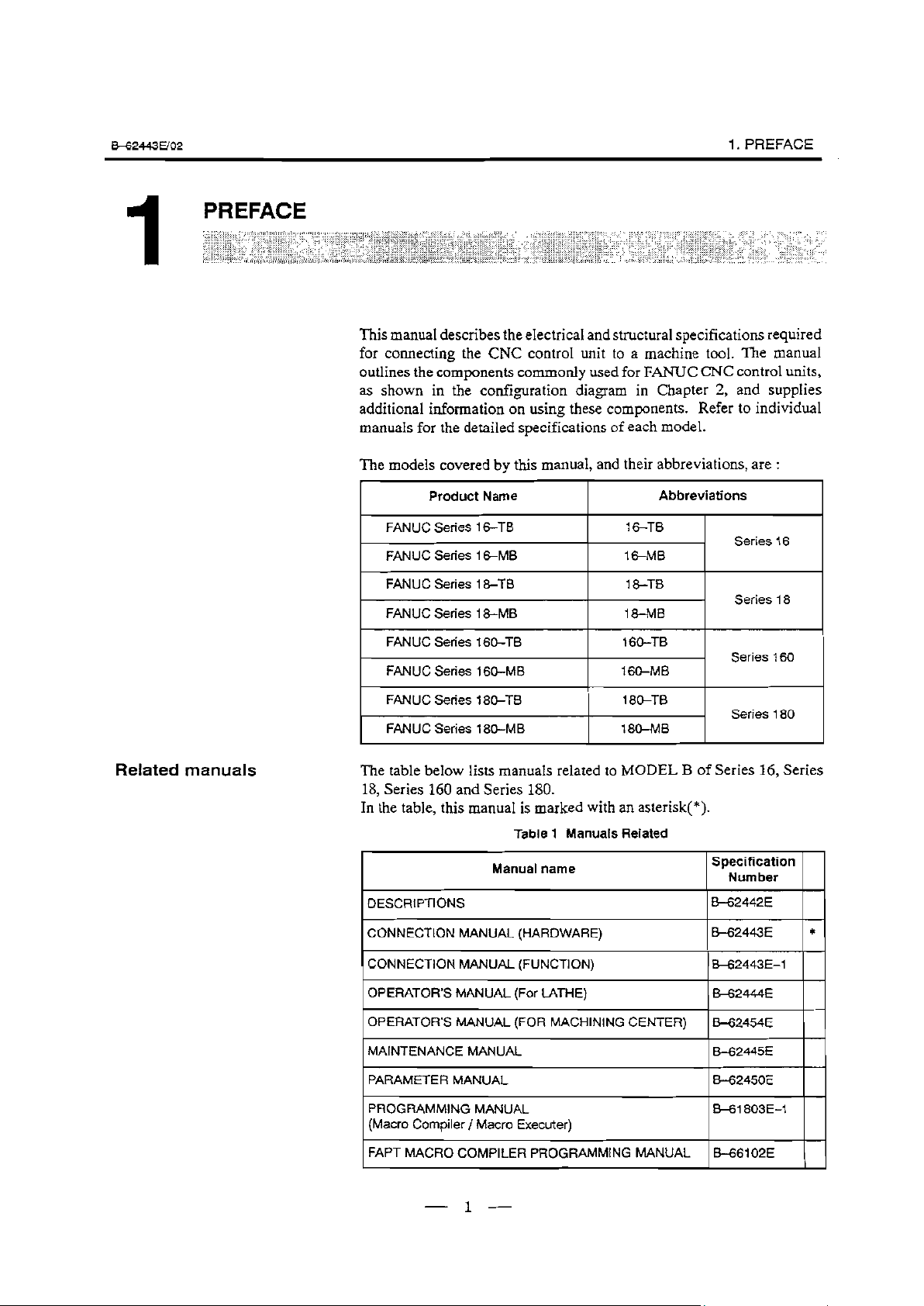
This manual describes the electrical and structural specifications required
for connecting the CNC control unit to a machine tool. The manual
outlines the components commonly used for FANUC CNC control units,
as shown in the configuration diagram in Chapter 2, and supplies
additional information on using these components. Refer to individual
manuals for the detailed specifications of each model.
The models covered by this manual, and their abbreviations, are :
\
. . . . . . . . . . . . . .
. . . .
.
.,,__,._, . . . . . . . . . . . . . . . . . . . . . . . . . . . . . . . . . . . . . . . >:...>:l: ,... ..y.: : ..: ..:.: ; ::::: :.:.: y+$:::. . . . . . . . .::,.. . . . . . . . .,.,. ._.,. .F.> .:..,.v ..v...,.>>: ‘. .,... ._
.‘.S.......,............. ~.~.L~...~.~,~.~.~.~ . . .
. .
. . . . . :.y.: :.:.:.:.: I:.‘.: ;. . . .‘...‘...‘...... “““:.y$$:::::::: ‘.‘.‘.‘.‘.‘.: ‘.:.‘.: 1, ;;:
. . .,.*...,..... .,.,.;.. .~‘~.,‘,.,‘,‘,‘,‘~.~.~,~‘.~ .:.:,:.:. . ..z.:.:‘:‘.,:,. >: .,.,
. ..::::... .*. . . . .., . . . . .
Product Name Abbreviations
FANUC Series 16-TB
FANUC Series 16-MB
FANUC Series 18-TB
FANUC Sen’es
FANUC Series 160-TB
FANUC Series 160-MB
.,.,....
. . . . . . .;::... . . ..i......... .;;
.
::, . . . . ...“.‘.
. .:.:.:.:.~,:.:.:.:‘.:.:,:,~.:.~.:.:.::.’.’,’”.’. .*.‘..+:.L* ‘,‘.‘.‘.‘.‘.:.:.:..:.:.~.:.:,:.~:.:.~~:.:.’.~...‘.‘...‘. . . t
.
.
. .:.:.: : : ,..
.
. . .,.. .,. . . . . . . . . . . . . .. ,... . . .
. . . . . . . .
. . . . . . . . . . . . . .
. . . . ..‘.‘.‘.~.~.~.‘.“.“.“. ..‘.
*...-..... . . . . ..‘.......... :.:.: ,.
:+>:.:.>>:.: ..,.:
.‘.1.‘.‘...‘.‘.’ ‘.‘. . . .I..,.,.,...,.,._...,. . . . . . . . .
. . . . . . . . ::
::
1 &-MB
. . . . . . . . . . . . .
,, ::::.:~:~:::#:i:i::::::::::::::;:.:.:.:.:.~:.~.:.:.:.:.~::~!~:~, y: :.,. .,
_...,... .;....,.,... ~..~..:.:.~:...:...~..:...~.,.:.:. . . .: .:. .:. ._ :.:.:.: :. . .:.:., . . . .,.. ..:....,.. ..,...;. ,.. ,+:. ~..: :.:.:> 1.1.: :. ,: ,:::. ..:.: :,, ,.. .:
._ . . . ..,.
. . . . . . . ..,....... . . . . . ..:: : >:...;.;:‘: ::::.:;‘::‘:.:., . ..,., ‘. .‘.‘I :::..:. . . . .T’ . :. :.:..:. .::. .‘.‘.‘. . . . . . . . ..., . . ._
. . . . . . . . ; . . . . . .
. . . . . . . . . . . . . . .>:.:.:.:.:.y . . . . .
:,:.:.:,:.:
. . . . . . . . . . . . . . . . . . . . ..~.....~. :.:.:.:.:.:.:.:.:.:.~...‘.‘.....:.:~ ‘..
. . . . . . . . .*..... . . . . . . ..‘.\’ ::
. . . . . . . ..‘. . ., :.:.:.:.:.‘.....,.,...,., ,..., ,.. ..,.....,. ._ ..,.
‘Q’.‘. .,.:.: >:.>:.:.: . . . . ..,....... .,...,...;: . .._ :.:.:,‘.~,:,~. : .:,. cc.::
::, . .~i.~.i’.‘..~.~.‘.~.~.~.‘.~.~.‘.’.’~.’ ...i..,.,...,. :., ;:.:. .,.:. ., ::.:.:.:: ::::::::::::.,.:.‘.:.‘.~:., .., ;, _. .,., ,... >: .,...,...,._. . . . . ,.,....... ,. . ,.. ., ,, .,,;,, ,, .,,. .
. . . . . . . . . ...‘.’ ‘. . . . . . :.:.:>,.:.: ; .:: .y:. ‘.
‘... :::, . . :.:‘::.‘:~::.p .:+:.:-: :.:.‘.:x.: :.:.;.:.:...:.:.:...‘.:.‘.:.:.~.:.:.: :.:.: :..:y+.:. q:;,::i : :_i; .,,,,,,... .;,,,. ..:,:, ~:
., ,.,. . .,. .,. ._ ,. . . . . . . . .;,...,.,... . . . . *.. .,...,...,
. ., . . . : . ‘.‘.++. .:.:,.,.., : . . . . . .
:.: . . .’ .:.:.:.: . .
.’ :j :::. :, :.:..,. .‘.. . . . . .:.,.:.:. ..:,
.i:... . . ,.::.; .,.:
,.,.....,.,..... :.,.:.:. . . . . .,..., .
16-TB
l&MB
18-l-0
18-M%
160-TB
160-MB
,.>:.v.~....,.,... ....v .
c+ .:-;:. ,. .:::. .:.: ~:.:.:.:..‘.‘.‘.‘.‘.‘. ::::,.:.. .
., ,... .: :.y.: :,:.>:.:.:.‘.:.: ‘...:.:.:.:.:.:.:.:... ,, y. .,
,’ y.:. ‘,:.:.:.:. : .::: ‘: . . . . . ..,.. ‘.. . . . . . . ..:...... . . . . . . . . . .*
:. . . ...‘.... . . . . . . . . . . . . . . . . . . . . . . . ..-.......... . . . .
.> ._, .
:: ‘.‘_.’ .: ‘.‘.‘.‘.‘.‘. : .::::,. .,.. . . ., _,,, 1.1,. ,,,.. ._.. . ., ,,,. ,.
.:, ..‘...“.‘. .: :.:.,
. .
. . . .,. . . . .,. . ._. . . . . . . . . . . . . . . , . . . . . .,. . .
;. . . . . . . . . . . . . . . . . . . : . . . _.:..;.. ._.:.._.;.. . . . .
..,..., _.;: ..:.: ‘.: .,.,
. _.;
. . . .I..:+ . . . .:.:.:.... ;..:
,.:, ..: ;z.:: ,.
:;:,... ‘.‘.:.:.‘.,. .,. .;,
,.
; . . .,
:.:.:. ..,.., .., . . ,:,:g:;: .+f.i:g:.:.: ;: :_:.:. :. .,. .:.
.,..,,..: . . . . . . . . . .
. 9 .
. . . . ::.> .,:,.,:,,: . . . . . . . . :: ..,. ..:.,:::
:, :.::.:
,.
. . . :.:.>,.:.: ,,, ;, . .:. .;.:: :,:.:.:.:,:.: :~‘p:.:. .,. .
. _. ,., . .
.._, :‘,‘:..:‘..‘.“.‘.:.‘:.‘.“:.‘,
. . . . . .,. . . . . . . .,. .,. . . ., . . . . . . . . . . . . ...+ . . . . ..,. . .,...... . . . . . . . . .,, . _ .,. .,,_. ..,..: . . . . . . . . . . . . . . . .:..:y.y.:.::.~: :.:.: .:, .:: ,.... _.... . . . . . . . . .‘.‘..‘-’ ‘. . . . . . . . . ..‘.‘...‘....I..‘..‘.‘.‘...‘...‘. .‘. . . . . .T.‘. . . . ..‘.....‘.....‘i. .,.,., ,.. ..,.
Series 16
Series 18
Series 160
.::.., . :.:. :.l.~: :.::, ;,i, 1::
*
. . . . . ... ::::;:.>:.:., ::::+,:: >:::::
.,.,. ., ,,. ,.,.; . . . . .
::,: .:“i:.: ::‘,...: ::
_‘, ;;~:;~: .,: :..,::
Related manuals
FANUC Series 180-TB
FANUC Series 180-MB
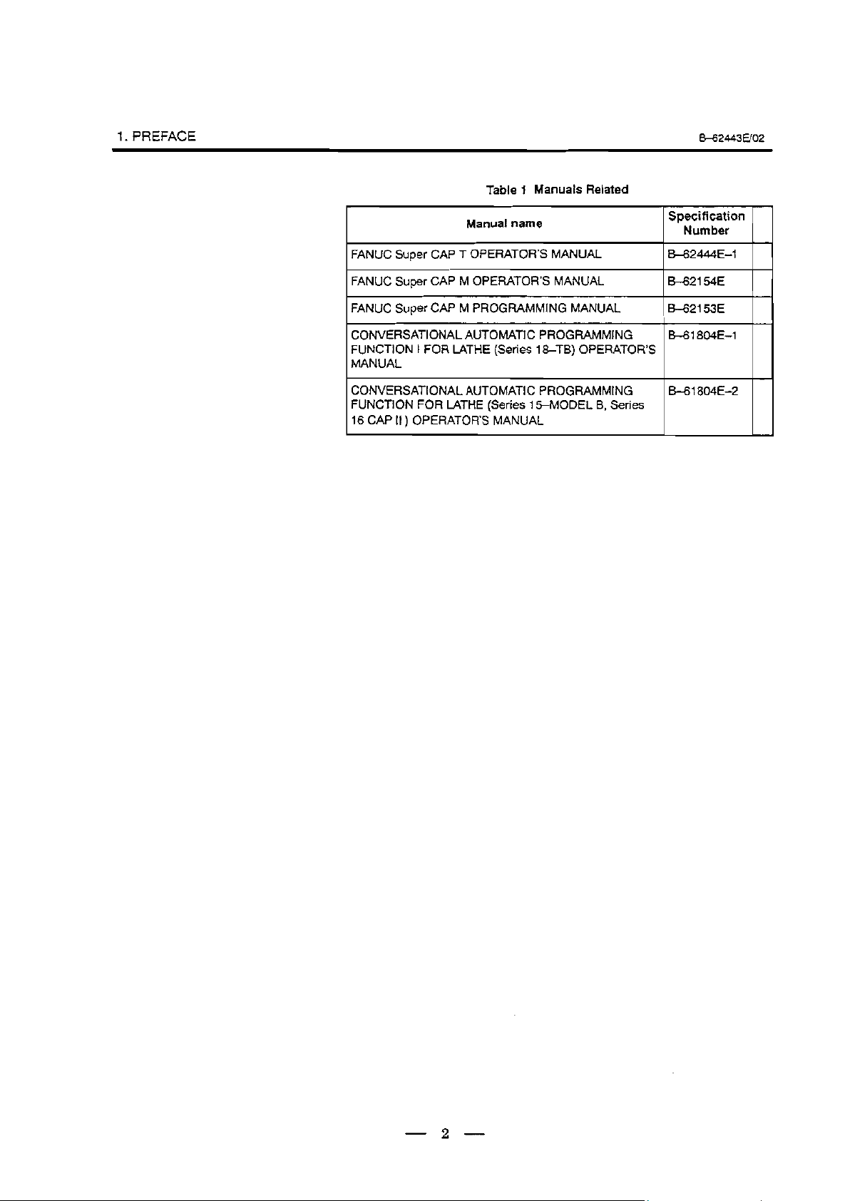
The table below lists manuals related to MODEL B of Series 16, Series
18, Series 160 and Series 180.
In the table, this manual is marked with an asterisk(*).
Table 1 Manuals Related
Manual name
DESCRIPTIONS
I
CONNECTION MANUAL (HARDWARE)
I
CONNECTION MANUAL (FUNCTION)
I
OPERATOR’S MANUAL (For LATHE)
I
1 OPERATOR’S MANUAL (FOR MACHINING CENTER) (&-62454E
MAINTENANCE MANUAL
I
PARAMETER MANUAL
I
PROGRAMMING MANUAL
(Macro Compiler / Macro Executer)
180-TB
180-MB
Series 180
Specification
Number
H2442E
I
B-62443E *
1w2443E-1
B-62444E
I
8-62445E
B-62450E
B+1803E-1
I I
I I
I I
1 1
I I
1 1
I I
FAPT MACRO COMPILER PROGRAMMING MANUAL
- l-
B-661 02E
Page 8
I. PREFACE
B42443Elo2
Table 1 Manuals Related
Manual name
FANUC Super CAP T OPERATOR’S MANUAL
FANUC Super CAP M OPERATOR’S MANUAL
FANUC Super CAP M PROGRAMMING MANUAL
CONVERSATIONAL AUTOMATIC PROGRAMMING
FUNCTION
MANUAL
CONVERSATIONAL AUTOMATh PROGRAMMING
FUNCTION FOR LATHE (Series ISMODEL B, Series
16 CAP II ) OPERATOR’S MANUAL
I FOR LATHE (Series I&-TB) OPERATOR’S
Specification
Number
8_62444E-E-1
I
2z-f
B-61 804E-1
s-61 804E-2
- 2 -
Page 9
&62443EJo2
:.:.:.:.:.:.:.:.:.~,:.~:~:.:.:.:...:.:.:.:.~:.:.:.~:.:
::.‘.:.:.:.:.:.:.‘.~.~.~.~....,‘,.,..:.,.:.~.:.~.~.~..~,~.:.~:.:.:.:.:‘.~:.:.:.:.:
‘.L’i.~.‘.‘.~.‘..,~.~.....~.‘.~.~,
.,.~.~.,.~.~.,.,‘,.~.,.~.,.,.,.~.~.,.~.~.~.
:.:.:.?:.:.:.:.~,:.:.:.:.:.:.:
.:.:.~:.:.~:,:.:.:.~.~.~~.:.~.:...~...:.~:.....:.~~:.~,..~::::~:.~.:;::~::.~.:.~.......~.~...~...............~.~...
~,~.‘..,~,-.‘.‘.‘.‘.‘.‘.‘.‘.~.~.~.~.~.~.~.’.~.’.
2
CONFIGURATION
. . . . . . . . . . . . . . . . . . . . .
. . . . . . . . . . . . . . . . . . . . . . . . . . . . . . . . . . . . . . . . . . . . . . . . . . . .:.:.:.:‘:‘:..‘:.:,.:.:,:...~;.: : : : . . . . . . . .
.:.:*..:.:.:.:.: :: ,.~:.“:~.:.,.:.:.‘.‘.‘.‘.‘. ,‘.“‘.:.:.~~:.,.~:,:, ..,.;.. ‘.‘.‘,‘.‘.‘.‘,‘,‘.‘:.:.:,‘,,
:+x>.+.:~.~: cc.:.: ::.:.. . . . . . . . . . . ,.
. . . . . . . . . . . . . . . . . . . . . . . . . . . . . . . . . . . . . . . . ..~.... :.>:.:.y. . . . . . . . . :.:.: ~.~,~,..~,~,‘....,‘,...,...........,. .,..., . . . . . . . . . . . . . . . . . . ..‘....*...* .
.‘.‘.‘.‘.‘.‘...‘.‘.‘.:.:.:.~:.:.~: . . . . . . . . . . . . . . . . . . . . . . . . . . . . . . . .
. ..‘. :. . . . ‘...
.:.:.:.p...:. . . . . . :.:.:.:.:.:.:.:.:.:.:,:.~:.~:,:.~.:.:...:.:..,..:..,...~~:.: :v... . .
. . ..v. . ...‘:.:.:.:.‘.‘.‘!‘:‘:‘:‘:‘:‘:.,’: :‘:‘:‘: :’
:.:.: . . . . . . . . . . . . . . . . . .:: : : : : : :: : : :: : :
.>;.:.: :.:.:.: :.: : :c.:.:.:.:.:.:.:.:.:.:.:.:.: :,:,:.:.:.‘.’ :,: :,..:...: :...:.:.
:.:.>: :.:.:.:.:.:.:.:.::.:.:.:.:.:.~:.:.’.:,:.:.:.:,;.:.:.:.:.:.:,:.:.:.:.... ..,.. . . ..‘.....‘.......‘........... . . .,.
. . . . . . . . . . . . . . .
. . . ._. . . . . . . . . . . . 1 . . . . .,. . . . .,.,. , . . . . . . . .,. . .,. . .,. . .
. . . . . . . . . . .
. . . . . . . . . :.:.:.:.: :.; ,...... . ..i. . . . ..~......... ,. . . . . . ..‘...‘.‘.‘..i.‘.. . . . . . . . ‘.. .,.....,. ::_.:.:,:.:. .,.,. . .,.,.,.,...,..,
.
,. . . . . . . .
. _. . .
.I.,.: ,..,.: :::..... . . . . . .
> ,...,,, ,,,.,.,. :.: . . . . ‘.‘.:,:.:.:.~,:.:.~~~,.:
. . . . . . . . . * . . . . .‘.‘.‘...‘.~.‘.‘.‘... ..a’.‘.. . . . .’
. ...:,.... ;.. . . . . . . . .* . . . . . . . . . . . . . . . . . . . . *. . . . . . . . . . . . . . . . . . . . . . . . . . . . . . . . . . . . . . . . . . ..S.............................. . . . . . . . . . . . . . . ,.........,........ ..,.... . . . . . . . . . . . . . . . . . . . . . . ... .... . .
. . . . . .,.. ., . . . . ,. .
,: . ::::‘:::::: ::::::::::::::: :::,y . . . . . . :.:.~.:.:.~:.:.:.:.‘.~~:.:.:.:.~:.~.~.:.:::::,~:.~: :.:.:.:::.: :.> ,..... . . . . . . . . . . . . . . . . . . . . . . . . . . .
.: :.:.: :.: . . .: %:.:...>,._ . . . . . .,,,.,...,. .,. .,:,: ::::::::::::::::::::.::,:: :::ij:.:.:.:.: .,.. . ._. . .., . . . . , ._. .,. . . . . . . . . . . . . . . .5.... . . . . . . . . . . . . . .‘.‘.:.:.;. .:...:::‘::::,::::.:.:.:.:.:.:.~.:.,.:.~.:.,.:,. . . . . . :,..::.:.:.:.: :+::~::+:+:.: :.:.:.: :.::::+:x.: :.:.:.::.:.~.:.‘................. . . . . . . .: .. +: :.:.:.:.‘.:.:‘.:.:.:.:.:.:.::.,:,:..
..;.... . . . . . . . .
. ;....:;. . . .::; . . ;, :. :... . .
.;
. . . .+ :. :, . ,. .,...
..,.... .;.., ;. . . .
.‘.‘...‘...... ‘i.‘.. ‘.‘.:.:.:.:.:.:.‘.:.;~ .,.;. ,.... ,... . . . . . . . . . . . . . . . . . ..i......... . . . . .
..‘.‘.~.‘.:*: . . . . . , . . . . . . ,.,.,., ..,.,...,.,...................,.......,.: y.:.: :.,.:.:..:. .
.5’.................... ‘...... “.‘.:,:,:.:.: :.:.:.:,:.:.:.:.:.:.:.~ ..,. :,:.: ..: . . . . . . .
._
. . . . ._. .,. . . . . . . . .,a,.. .,. . .,. . .,
. . . . . . . , . . . . . . . . . . . . . . :,:.?:.:.:.~f..‘.‘... .._ . . . . . . . . . . . . . . ..‘.‘..‘...‘.*.‘.“.‘...:.:.~:.:.:.~:.:.:.:.: ,....... . . . . . . . . . ,.,../..._... .;,.
_.:,... . . . . . ..: ,.....,. .~.~.,.........,.,.,...~.~~,. .,:,: :.:.:,:, :.:.:‘:~:.:.:.:.:.~~~. .:.:.y.: :.:.:.:.:.>:.: .,.I... ,...,. .,.....,.. s.: :.:.I.: :.,.:.:.:.:.:.:,~:.:.:.. ..,..., :.:,::::::::::,:..:. :.:,:. .~.:.;.:.:,:.‘.‘........, . . . . I . . . . . . . . . . . . .,..I.. . . . . . . . . .
. . . ...‘.
‘.‘.:.:...:.:.:.:.:.:.~.:.:.:.:.:.~:.:.:.:.~:.:,~:.:.:.~ ,.., :. . . . . . . ..,....... . . . . . . . . . . . . . . . . . . ..i.....‘....‘...‘.‘.‘............. . . . . . . . . . . . . . . . . . . . . . . . . . . . . . . . . . .,
. . . . . . .,...,.,.....,. . . . . . . . . . . . . . . . . . . . . . . . . . . . . . . . . . . . . . . . . .‘.“.>>~:.: :.:.:.:.~~:.:.:.:‘~:.: : ~.:.:.:.~)~:.::.:.:.~:.:.:.:.~~:.~: :.:.>: :.‘.:.:.:.:.:.:.~:...~ .,.. ,.,.........,.,.,. ::.:.
. .i’*.. .‘.....‘.... . . . . . * . . . . . . . . . . . . . . . . . . .
:: ._.. . . . . . . . . . . . . . . . . . . . . . . . . . . . . ..,...*...
‘...... . . .._ . . . . . . . . . . . . . . . . ..,.......... . . . . . . . . . . . . . ..,.......... . . . . . . . . . . . . . . . . . . . *.... . . . . . . . . . . ..:.._.... I..
. .
.
.
.
.
. . . . . . . . . . . . . . . . . . . , . ,.,.....,.,.. . . . . . . . .
. : . ...:;. ..,..‘.‘.. ‘.‘.L......‘...........‘.. ..‘.‘.‘...‘.:.:.:.~:.~. ., ..,.,..... . .,.,.
. . . .,. ._. .,...,. . . . . . . . . . . . .,. . ., .
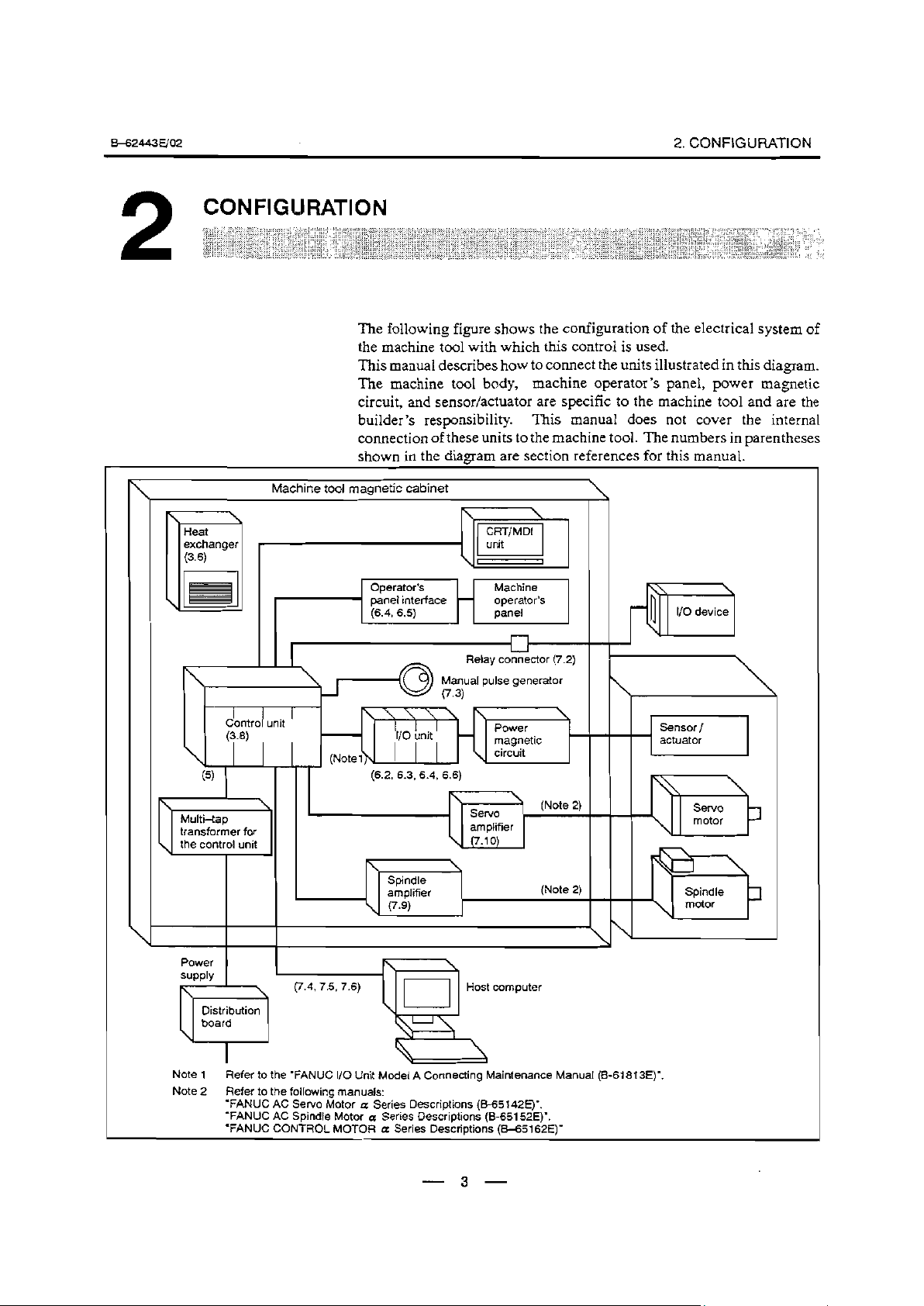
The following figure shows the configuration of the electrical system of
the machine tool with which this control is used.
This manual describes how to connect the units illustrated in this diagram.
The machine tool body, machine operator’s panel, power magnetic
circuit, and sensor/actuator are specific to the machine tool and are the
builder’s responsibility. This manual does not cover the internal
connection of these units to the machine tool. The numbers in Darentheses
shown in the
. . . . . ..‘*‘.‘.‘.:.: .,....... .;.. ._...,. :.:.: ‘:.:.:.:.~~:.“.‘.‘.‘.......‘.:.:.~.:’.: . . . . . . . _. . . . _
, .
.:.:.:... ‘......,.,. . . . . . . . . . .
. .
.
.:.~~,~:.~.:.:.:.~.~.~.~.~~.~.~,~.~.~,~.~.~.~.~,,.~~.~. +:.:.:.:,:.‘.‘.‘.’ .:... .‘.‘.‘.‘.‘,‘.‘.‘.‘.‘...‘.~.~.~...’.:.: :.:.:.:.~:.:.:.:.:.‘.‘....,..........’,.,... . . . . . . . . ..,......‘......................,..’. . . . . . . . . . . . . . .?. . .
. . . . .
.
,.,...,, .,.....,.,.,.*...... y:.:.:.:.
. . . . . . . .,., . . . . . . . . . . . . . ,*, ,.,... ., .
:: :::*: ::::::““‘“.“‘~.“‘~.‘...~..‘.:::::,:::::::::::::‘:i:i:: :..::: ~~‘:~,:i:.:l,‘:
. . . . t.. . f
. . . . *. . . . . . . ..L....... . . . . . . . . v.:.:.:.y.:.:. .: . . . . . . . . . . . .;,.,.;, . . .
. . . . . . .~. . . .,,. .
diagram are section references for this manual.’
. .
” ..:_:.:c.:.:.: :-:::.:.:.:.......::. . . . .
. . . . . :.I.>
. .,.,.,. . . .,. . . .
. . . . . .
. . . . . . . . . . . . . .,. . . . . ._.
.,,,.:,,....,.....,.........,
. . . 9 ,.,. ._. . . . .,..,.,. . .,* . .
. . . . . . . . . . . . . . . . . . . . . .
r:..:.: :.:.:.:.:.:.:.:.:.s: . . . . . . . ‘.‘.‘.:+.x...... ..‘..........................,...,.., . _.
. . .,.,.;.. ‘.: :.. >:.:.: .(.,. :.:.:.:.:.:.‘.:.:.:.‘.:.:.....~~’.~.~:.:.:.~.,.:.. ..‘...‘.....‘.‘.....‘.~.~,~,; ~:,:,: :,:.:,: :.~:,. .:.:.:.:‘: :::::,:::::::::::::j::: ._ _. ._
.,... ..‘.‘........’ . . . . ..‘~‘.
. .,,~: :::‘:‘::s >: . . . . . . . . .._. ..,.... . . . . . . , . . . . . . . . . . . .
. . . ..,.. . . . . . . ..~.~.~.~.~.....~.. .‘... ~.5....~.~.~,.,.,~......,. ..:. . .:.. . . . . . . . ..I,. . .,..., . . . .
. . . . _.
. . . . . . . . . . ~,~,~,~...5~.~, .
. . . . . . . . . . . . . . . . . . . . . .:.:.:+:.: . . . . . ..I... . . . . . . . . . . . . . . . . . . . . . . . . ..,.i... ., ..,..
.:.::.:q..
. . . . * . . . ...‘...‘.‘.‘.’ ‘.‘..Z....... . .
. , . . . . . . . .._......... ;,.*..:,.*..:. . . . .
2. CONFIGURATION
‘. . -*.*. . . . . * . . . 5............. .:........:. .:
. . ‘...‘. . .‘.‘.‘...L..... ‘.. ‘.‘.:‘:.:.~:.:,:,:,:., :,. ,..,, . . ..,..,
. . . . . . . . . . . . ...‘.....‘.‘.‘.. ‘... .
.
. . . ..*....... ..,..*.._...:..
. . . . . . . . . . . . . ..,.. ‘,‘,‘.‘.‘.‘,‘.‘.‘.:.~
. . . . . . . . ,....::..,.......;.. . . . . . . . . . . . . . . . . . . . .
. . . . . . . . . . . . . . . . . . . . . . . . . . . . . .
. . .
. . . . . . .
* . . . . . . .
.
. . . . . . . . . . . . . . . . . . . .
.
““““‘::::y .,...,.....,.l.,.,..,.~. ,.;.... ..,.,,::.‘.:~ ,:,..:,: ,.,.:,:.::,...
:.. :‘.+.:.:.:.: . . . . . . . . . . . . . . . . . ‘+..
. . . ..,..‘. .
‘...‘..,..‘.............. . 7.::. ...:i:::::::~.~:,:.:.:.:. . . . .., . .
:. :.........-..,.....,.. .‘.‘.‘.,.: 1. .+.....,...,,........,...,, > :. . ..,. . . . ., ,.
.‘.‘_‘.‘.‘...~...... . . . . . . . 1.‘. .,...~.~....,,.,..,,.,. .,, .:.::.: : : : :. .:
. . . . . :.:i,... .:..:......:
.:+ . . . . . ..i...... . . . . . . . . . . . . . ,.... . . . .
,....,...,.,.,., . _.;;;.. .._ ..,...............,.....,.
.‘.... ,._. .,...,... . . . . . . .., . . .
. . . . . . . . . . . . . * ..,.... . . ..a . . . . . . . . . . . . . . . . . . . .._....... . . ._. ._. . .,
:.: . .,.. ..,.. . . . . . .,. ‘.‘.T ,. .:,
.‘.‘.‘.‘. :::. .‘. . ..‘.. .;. . . . . .,..
,.: 1.1 : >I.,.: I.‘.‘. :. ,c; .:; ..‘.,.;,.
.: :::. . . , . . , . . :.. . . :;.
.
. . ..*+. . . . . . . . . . . . ..:.
. :..:.. . . . . . . .
. . :.-:: .‘... . ...*..... . . . . . . . . .: .: . .
:.:.:.:,:. .:,:,,, ,:,: _:,:.:. .:
,. _.
:,.. ,,,,_ .:
._ ‘.: :.
:., T.1 : :.:.:,:.,_:: :.:+
. . . .‘.>,.:.:.: ,.:: ..;,:
I Inl I
1
Contro unit
.
(3 8)
(5)
1 Multi-tap
Machine tool magnetic cabinet
Operator’s Machine
Panel interface - operator’s
(6.4, 6.5)
, \ I
-
I
I II
I I Sninflle
-r- l -*-
amplifier
\ (7.9)
panel
Relay connector (7.2)
A_. .,I ,..I-- ------*--
Manual purse gewrarur
.
(7 3)
magnetic ’
circuit
(Note 2)
L
\
(Note 2)
\
.
\
1
I I\
sor /
1
actuator
J
\
b
Power
supply
I
I
Note 1 Refer to the “FANUC I/O Unit Model A Connecting Maintenance Manual (B-61 813E)“.
Note 2
Refer to the following manuals:
‘FANUC AC Servo Motor a Series Descriptions (R65142E)“.
l FANUC AC Spindle Motor a Series Descriptions (B-651 52E)“.
‘FANUC CONTROL MOTOR a Series Descriptions (B-651 62E)”
‘“gi y m puter
1
!
- 3 -
Page 10

3. INSTALLATION .
“‘..“.:.:‘:.:.‘.~:.:.~::,~:.~.~:,~~~~~~~,~,~~.~.~..
:.:.~.:.:.‘.:.:.:.:.:.:.:.::.:.:.:
..5..‘.....5...................
“‘.:,:‘:‘:‘:.~:.:,:,~~.~~~..
..‘...‘...‘...‘...i........‘.....’.’.....
~.‘.~.~.~.‘.‘.~.‘.‘.~.~.~.~.~.~.’.~.’.~.~.~,~.
“:.‘::.~~:.~:,~:.‘.:.~:,:.~,~~,,~,~~.~~.~.
:.:s.:.:.:.j:.~.:.::.:.~.~.~.~.:.:.~:,:,:,:.:,:
~.~.~.~.~~.‘.~.~.~.~.~.~.~.~.‘.~.~.~.~.~.~.~.~.~.~.~.~.~.~.~.~.~.~.~.~.~.~.~.~.~.~.‘.‘.~.~.’.~,~.~.~,~,.
~.~.~.~...~,....
.5’.‘..‘.~.‘.‘.“.‘.‘.‘.‘.‘...“..,’.’.....~.:.:.~.:.:.:.:.:.~.:.:.~:.:.~‘....
.-..‘.‘..‘.................L....’........
&62443E/o2
3
INSTALLATION
.’ * . . . . . .f * . . . . . . v... . . . . . . . . . ..I....
..‘.‘.....‘................,~..... . . . . . . . . . . . . . . . . . . . . . . . . . . . . . . . . .
. . . . . . . . . . . . . . . . . . . . . . . . . . . . . .._....... . . . . . . ~.~.‘,~.~.~..,....~,~.~.~.~,~.~.~.~...’..,~.~. .:,:.:...:
..\.... ..,., . . . . . . . . . . . . .
. . . . ..-........i . . . . . . . . ...‘.‘.. . . . . . . . . 55. . . . .
. . . . i::::::::::::,::::::.:.~:.... . . . . . . . ..r..+.....
.*......:...... . . . * ..,.. .,..‘...f...,. .,. . .,.:... . ..: . .:.:.:.:.‘.:.:.:*:i.>‘.::.:.‘.: :...:.~.~:.f.:.:.:.~~.. .,....... ..:, :.:.~~ :,:, ::+:.: ~ ,.,...,.,.,..... .,.,.,. . . . .
.~.~.‘.‘.‘.‘,~.‘.‘.~.~......,~. .‘.‘i...‘.‘. .
. . . . . . . , . . . . . . . . . . . . . . . .._. . . . . . . . . . . . . . . . . . . . . . . . ...+... . . . . . . . . . . . . . . . . . ..,. .+...,. ~ .,.,.
‘.‘.‘.’ . . ..‘.‘..~‘...5..‘.‘............
f:.:.:.:.:.:.:.: :.~f:.:.:.:.:.:.:.:.:.:.:.:.:.:.:.~.:.:.: :
.~~:.:...:,~:,:.::::::::::::::::~:::~:::~:::.:.:.:.:.:...:.:.:.:.:.:.:.:.~:.:.:.~:.:.:.~:.:.:.:.:.:.~
. . . . . . . . . ...*...
.,.,...,.,., . . . . . ..._...+.. . . . ,...Z_.~.,‘~.,.,.~ 5 .._....... . . . . . . . . . . . . . . . . . . . . . . .,.......:....
:::::::::::j.:::j:::::::::‘::~~::::i::::’::.:. .
f.............,.,.. * . . . . . . . . . . . . . . . . . . . . . . . . . . -: ,.....I..... . . . . . . . . . . . . ‘s’,., . . . . . . . . . . . *....,* . . . . . . . . . . . . . . . . . . . . . . . . . . . . . . . . ..,...:.
.,. . . .,. . . . .,., . . . . . . . . . . . . . . . . . . . . . . . . . . . . . . . . .
. . . . . . . . * . . . . ..‘.......‘.5..‘......‘...‘... ..:.-...........- . . . . . .,.,. ..‘.., . . . . . . . . . . . ..,.:..........,.:;.. ,...:. . . . . . . . . , . . . . , . . . . . . . . . . . . . . . . . . . . . . . . . . . :.:.:.:.~:.:.:.:.:.~.:.~.~:.~...’...........’...‘.‘..‘.‘. .
. . . . . . .
. . . . . . . . .. . . . . . . . . * . . . . . . . . . . ,.... . . . ...* * . . . . . . . ..I....... . ..,.......,.. :.:
. . ..*.........
..‘.......S....‘.i....‘...‘..........
*
. . . . . . . . . . . . . . . . . . . . . . . . . . . . . . . . . . . . . ,.,.i~.~.,.,...~.,...,.~.,.
:.:*:.:.:.:.: . . . . . . . .
,.. ,...... ,.,.. ,... . . . . . . . . . . . .
.; ..,.......,..., ..,.....,.....,.,.. , ,.,.,...,. . . . . . . . . . ..,...
. . . .
. . . . . . . . . . . . . . . ;.:2.:.: : ..:.:.> . . ,.. . . . . . . . . . . . . . . . . . . . . . . . .
.
. . . . . . . . . . . . . ..,..,..,.......................,......,,..
. . . . . . . . . . . . . .
. . . . . . . . . . . . . . . . . . . .
. . .
. ..‘.‘. . . . ..‘.L..‘. : ‘...... . . ‘.‘.‘...’ ‘..::.-.
. . . . . . . . . . . . . . . . . . . . . . . . . . . . . . . . . . . . . . . . .
. . . . . I . .~...,...,.,.~.,.,.~.,.~ . . ..,..,, .,,,.,.,.,.l. . . .., ,.... . . . . ...*......... . ..v...‘...‘.
:
: : :. :
:: ::: : : : 1.1 ..,.
. . . . . . . . . . .
. . . . . . . . . . ,...,.,..._. .;,. . ..., :,:,:,:.: :::::::::‘.:::::.:.~~~~.....‘.‘..’.’.’.’...*...:. . . . . . . . . . . . . . . . . . . . . . . . . . . . . . . . . . . , .,...,.,...,.,... .,.,.....,.,.....,...,... . . . . . . .
. ,.,.,.,.,..., ._..... :,:_:.: .:,:_:,: ,:.:,..::,,..,.,. . . . . . . . . . . . . . . . . . . . . . . . . . . . . . . . . . . . . . . . . . ,..... .I...... . . . . *. . . . . . . . . . . . . . . .
. .
,~:....;;: :...., -.. . . . . . . . .:: . . . ..L...... . . ..* . . . . . . . . :‘:.:.:.:.I::.:.~:.:.:.:.: :.I~:.:.:.:.:.:.:.:.: :.:.:.~~:.:.:.:.:.:.:.:.~.:.:.:.~.:
.
. . a.. . . . . . . . . . . . . . . . . . . . . . . . . . .:,..:. ~ ..,... . . . .
. . . ,.... t ,.,.,.......,.,.,.......
.:.:,:.‘.:.:.:.:.:,:.~:..,... ..Z. . . . . .
. . . . . . .,.,. ‘.“:.‘.:3:.:.:.:.:.:.‘.:.:.:.:.~~. . . . . . . .: : ::: : :::
:.:.:,: :,:,:,:,: . . . . . . . . . . . . ,.,.,...... ,‘......I..........,. . . . . . . . . . . ..‘.‘.‘.‘...’ . .’ -. . .
.‘... : . ..‘.....‘.‘.‘........‘.‘.. ‘.‘...’ ..‘...... L....
. . .
. . . . . . . . . . . . . . I . . . . . . . . . . . . . . . . . . . . . . ..‘..........
., ;.,,., ;. . . . . . . . . . . . . . . . . . . .
.,.~.,.,...,.,.~.~.,.~.,.~.,.,.,.~ ..,
..: .:;:.:
. . .
. .
. . . ..,...,.............,. _ .............,.,...r.,...
..‘.........‘...,. ..,..f .,... . ..‘. .:...... . . . . . . . . . . . . . .
‘...i.
.
. ..,.,.
.2.::.:.:.~.:,::‘:::‘:.:.:.:.:.:.:.~,~.~..~.:.:~.:.~~.:.:.:.:.:.~~.,~..
. . . . . . . %... . . . . . . . . . . . . . . . . . . . . . . . . . . . . . . . . . . . . . . . . * . . . . . . . . . . . :.‘.:.:.f:.~.~. .:.:.I~:.:.:.:.:.:.:.:.~ ..,.... . . . . . . . . . . . . . . . . . . . . . . . . . . . . . . . . . . . . . .
. . . . . . .
. . . . . . . . . . . . . . . . . . . . . . . . . ,.,.......,.I........,............ .
. . . . .‘..‘.’
.‘...’ .:: ‘.‘...‘...‘.f:.:.:.:.:.~:,:.:.:.:
. . . . . . . . . ..r..............................
.
. . . . . . . . .
, ,
. . . . , .
.a.... . . . . . *:.. . . . . . :.:.:.~:,:i,:.:,:,:,~,:.~ . . . . . . ..I... * . . .._.... . . . . . . . . . . ..::,...... I ,.(.. . . . ...* . . . . . . . . . . . . . . . . . . . . . . . ‘.:,:.:.:.:,:.~~:,:...:.:.:.:.:.:, . . . ..‘........... , ,.... . . . . _..-, .:.:.>:.:
.:.>:
:.:.:.‘.:.:.~:.:.:.:.~:.:.~.~:.:.:.:.: . . . . . .
. . ,.......
. . . . . . . . . . . . ..,.. . . . . . . . . . . .,... ,........ . . . . . . . . . . . . . . . . . . . . . . . . . . . . . . . . . . .._........ . ..> . . . . . . . . . . . . . . . . . ..f .,...:............ .,...................,.......,.. ..,.,.
. . . ..f... . . . . . . . . . . . . . . . . . . . . . ..*................
. . . . . . . .~.,.,.~.~.~.,.~.,.,.~.~.~.. . . . . . . . . . . . . . . . . . . . . . . .
.
. . . . , . . . . , . . . ..i............... . . . ..,...,., . . . . . . . . ..,.......:............... . . . ,.......;. . . . . . . . . . . . . . . . . . . . . . . . . . . . . . . :.:.:.:.: :: :.:: : : : : :: :
. . . . . . . .._ . ..,... . . . . . . . . . . . . . . .
:......... . . . . . . . .<...:,:.:.: .:.:. :.> :.:.:. ~ :.~.~.:......,., * . . . . . . . . . . . . . . . . . . . . . . . . . . . . . . . . . . . . . . . . . . . . . . . . . . . . . . . . . . . . . . . . . . . . . . . . . . . . . . . . . . . . . . . . .
. . . . . . . . . . . . . . . ,.,‘..,.... . . . . . . . . ..L.. . . . . . . _...... ..,.f.. ..:..;... . . . ..::,.. . . . . . . . . . . . . . . . .:..::: . . . . . . . . . . . . . ..;:. . . . . . . . . . . . :,.......,. >:.:.>..>
. . * . . . . . . ._. . . . . . . . . . . . . . . . . . . . . . . . . . . . . . . . . . . . . . . . . . . . . . . . . .,. . . . . . . . . . . . . . . . . . . . . . . ._. . . . .,. . . . . . . . . . . . . .‘.‘.‘.‘.‘.~.~.~.~.~.~~.~ . . . . . ‘i.‘...‘...‘.‘.:...~.:.
.. . . ..,...,...,.....,.... . . . . . . . . . . . .
. . . . . . . ( . ,
..L.........,......... . . . . . . . . . . . . . .._
.:::... . . . . . . . . . . . . .P.‘.‘.‘~..‘..‘.~.‘...~.~,~ . . . . . .
. . . . . . . . . . .
.I,.*.. . . . . . ..I . . . . ..L.....
. . . . . . . . . .
. . . . . . . . . . . . . . . :.:.:.:.:.~.‘.“.‘.......~...~.‘.~
..,.....,.,.......,.....,.......,.....,.... . . . . . ..f.....................
. . . . . . . . . . . . . . . . * .
. . . . . . . . . . . *. . . . . . . . . . . . . . . . . . . .‘i.‘. .‘...........5....5..‘. . . . . , . . . . . . . . . . . . .
. . . . . . . . . . . . . . . . . . .
. . . . . . . . . . . . . . . . . . . . . . . . . . . . . . . . . .
. .* ..‘.‘.’ ‘.............. . ...-...‘.‘...*.- -.....-........... . . . . . ‘. . . . . . . . . . . . . . :.:.i!.:.:.:.:.:.:.~:.~. :.‘:.‘.‘. . . . . . . . f .;_
..,.:,:. y: .:,., >; +:,‘*‘,....” . . . . . . . . . . ,.,.;,... :: . .
..i......; . . . . . .
<.... . . . . . .x. .Y+,..... Z...
. .
,+:.:, ~.
..,, ~~~~: ~ :.:, :z . . . . . . . . . . . . ., . . . . . . . . . . . . . . . .:.::
>:.>>:.>:.:.: . . . . . . . . . . . .
,.I..,.,...,._.,.Z.... .:.:.~:.:.:.:3:,:...‘.......‘.‘.
. . . .
. .
:.;.:.:.:.
:.:z.>>:. :.y.:.>:
.
. . . . . . . . . . . . . . . . ..,...,.....,
,.,.,...,. . . . . . . . . .. .. .....,.............,. . . . . . es..:...*...
,. .,. . . . . . . . . . . . . . . . . . . . . . . .
. . .‘...........‘.. ....’ ‘...‘.. ..’ . . . . . . . . . . . . . . . . . . . . .,.,.,.,.i,., . . . . . . . .
..,........ * . . . . . . . . . . . . .,. ;..
. . . . :.:...:.:.: :.:.:.: ::.: :.:.:.:.:.:.:.:.:.;.:.:.:..
.
. . . . . .,.,........... .~.,.,.,.~.,.,.,.,.~
. . . . . .
. . . . . . . . . .
. . . . . .
:.:.:.~:.:.:.:.:.:.:.:...’
. .
,...,. ::.,.:, :. .:...>:.:
: :.>:.:.:.:. . . . ::
.>>>?:.:...:.:.:.
.,._ * . . . . . . . .‘.’
.
._ ,. .
‘. .‘...., ;, . . . . .
.‘.:.:.:.‘.>:.:.:..
. . .
. . . . . . ..‘......................
>.“.‘.‘. ..‘.‘..... .‘....
.‘.‘.:.:.‘.:.:.:.:.~.‘.: y.>:.:.>>:.:.>>: .
. . . . . . . . . . . . . . . . . . . . . . . . . . . . . . . . . . . . . . . . . . . . ..I 2:. Q.....,‘.‘... . . . . . . .
..:.: ‘.:.,.:,:.:.:.: :,: ,., ,.,._ ._,.,.,., ..,
:.:.
. . ,..... ,.......,. .:.:r.,.:‘::.:
. .
. . . . 9 . . . . . .’ . . . *...,.a %v..:..::.:
. . . . . a,. . . . . . . .,. . . . . . . . .,.,... . . . . .
. . . . . . .
,‘.‘,‘.,.:.:.:.,, . . . . . .
:.y .:.. .
. :: . . . . . . . . . . .
.,...,., ;...
- . . . . . . . . . . . * .
. . . . .
.>>
. .,.
- 4 -
Page 11

G62443E102
3. INSTALLATION
l
31
ENVIRONMENTAL
The peripheral units, such as the control unit and CRT/MIX, have been
designed on the assumption that they are housed in closed cabinets. In
this manual “cabinet” refers to the following:
REQUIREMENTS OF l
CNC
0
The environmental conditions when installing these cabinets shall
conform to the following table. Section 3.4 describes the installation and
design conditions of a cabinet satisfying these conditions.
Change in
temperature
Vibration
Cabinet manufactured by the machine tool builder for housing
the control unit or peripheral units;
Cabinet for housing the flexible turnkey system provided by
FANUC ;
Operation pendant, manufactured by the machine tool builder,
for housing the CRT/MD1 unit or operator’s panel.
Equivalent to the above.
45O
Room temperature 1
Relative humidity L
1 In operation:
1 Normal machine shoe environment
Environment
I
1 and/or organic solvent is relatively high.)
In operation
In storage or
lYC/minute max.
Normal
Temporary (within 1 month)
uhe environment must be considered if the cabinets
are in a location where the density of dust, coolant,
transportation
0.5G or less
0” to
-20" to 60"
I 75% or less
of less
95%
32
IiSTALLATlON
CONDITION OF
SERVO UNIT
33
PbWER CAPACITY
?
Room temperature
Relative humidity
Vibration
Environment
In operation
In storage or transportation
95% RH or less (no condensation)
I
0.5 G or less
The unit shall not
bricant or cutting chips.
be exposed direct to cutting oil, lu-
o”c to +55”C
-20°C to +6O”C
The power capacity of the CNC control unit, which in this section means
the specification required for the power supply, is obtained by adding the
power capacity of the control section and the power capacity of the servo
section.
The power capacity of the control section includes the power capacity of
the control unit, CRT/MDI, I/O unit, and operator’s panel interface.
Power capacity of
the control section
Power capacity
the servo
of
section
When
power supply Al is used and AC out-
put terminals CP2 and CP3 are not used.
When power supply Al is used and AC out-
put terminals CP2 and CP3 are
When power supply BI is used and AC out-
put terminals CP2 and CP3 are not used.
When power supply BI is used and AC out-
put terminals CP2 and CP3 are
Depends on seNo motor type.
used.
used.
0.3kVA
0.8kVA
0.5kVA
I I
1 .OkVA
I I
1
,
5
Page 12
3. INSTALLATION . 842443uo2
3.4
DESIGN AND
INSTALLATION
CONDITIONS OF THE
MACHINE TOOL MAGNETIC CABINET
When a cabinet is designed, it must satisfy the environmental conditions
described in Section 3.1. In addition, the magnetic interference on the
CRT screen, noise resistance, and maintenance requirements must be
considered. The cabinet design must meet the following conditions :
.
The cabinet must be fully closed.
The cabinet must be designed to prevent the entry of airborne
dust,coolant,and organic solvent.
Cabinets that let in air may be designed for the servo amplifier and
servo transformer provided that they :
0
Use an air filter on the air inlet ;
0
Place the ventilating fan so that it does not blow air directly toward
the unit;
0 Control the air flow so that no dust or coolant enters the air outlet
The cabinet must be designed to maintain a difference in temperature
of 10°C or less between the air in the cabinet and the outside air when
the temperature in the cabinet increases.
See Section 3.5 for the details on thermal design of the cabinet.
A closed cabinet must be equipped with a fan to circulate the air
within.
The fan must be adjusted so that the air moves at 0.5 m/set along the
surface of each installed unit.
CAUTION : If the air blows directly from the fan to the unit, dust
easily adheres to the unit. This may cause the unit to fail.
For the air to move easily, a clearance of 100 mm is required between
each unit and the wall of the cabinet.
Packing materials must be used for the cable port and the door in order
to seal the cabinet.
Because the CRT unit uses a voltage of approximately 11 kV, airborne
dust gathers easily. If the cabinet is insufficiently sealed, dust passes
through the gap and adheres to the unit. This may cause the insulation
of the unit to deteriorate.
The CRT/MIX unit must be installed in a location where coolant
cannot be poured directly on it. The unit does have a dust-proof front
panel.
Noise must be minimized.
As the machine and the CNC unit are reduced in size, the parts that
generate noise may be placed near noise-sensitive parts in the
magnet& cabinet.
The CNC unit is built to protect it from external noise. Cabinet design
to minimize noise generation and to prevent it from being transmitted
to the CNC unit is necessary. See section 3.7 for details of noise
elimination/management.
0
The units must be installed or arranged in the cabinet so that they are
easy to inspect and maintain.
- 6 -
Page 13
&-62443E/o2 3. INSTALlATlON
The CRT screen can be distorted by magnetic interference.
Arranging magnetic sources must be done with care.
If magnetic sources (such as transformers, fan motors,
electromagnetic contactors, solenoids, and relays) are located near the
CRT display, they frequently distort the display screen. To prevent
this, the CRT display and the magnetic sources generally must be kept
300 mm apart. If the CRT display and the magnetic sources are not
300 mm apart, the screen distortion may be suppressed by changing
the direction in which the magnetic sources are installed.
The magnetic intensity is not constant, and it is often increased by
magnetic interference from multiple magnetic sources interacting
with each other. As a result, simply keeping the CRT and the magnetic
sources 300 mm apart may not be enough to prevent the distortion.
If they cannot be kept apart, or if the CRT screen remains distorted
despite the distance, cover the screen with a magnetic shield.
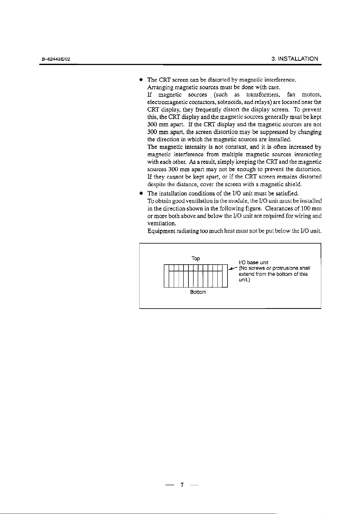
The installation conditions of the I/O unit must be satisfied.
To obtain good ventilation in the module, the I/O unit must be installed
in the direction shown in the following figure. Clearances of 100 mm
or more both above and below the I/O unit are required for wiring and
ventilation.
Equipment radiating too much heat must not be put below the I/O unit.
6ottom
l/O base unit
H (No screws or
extend from the bottom of this
unit.)
protrusions shall
7
Page 14
3. INSTALLATION .
3.5
THERMALDESIGN
OFTHECABINET
3.5.1
Temperature Rise
within the Cabinet
&-62443E/O2
purpose of the thermal design of the cabinet is to limit the difference
The
in temperature between the air in the cabinet and the outside air to 10°C
or less .when the temperature in the cabinet increases.
The internal air temperature of the cabinet increases when the units and
parts installed in the cabinet generate heat. Since the generated heat is
radiated from the surface of the cabinet, the temperature of the air in the
cabinet and the outside air balance at certain heat levels. If the amount
of heat.generated is constant, the larger the surface area of the cabinet, the
less the internal temperature rises. The thermal design of the cabinet
refers to calculating the heat generated in the cabinet, evaluating the
surface area of the cabinet, and enlarging that surface area by installing
heat exchangers in the cabinet, if necessary. Such a design method is
described in the following subsections.
The
cooling capacity of a cabinet made of sheet metal is generally 6 W/“C
per lm2 surface area, that is, when the 6W heat source is contained in a
cabinet having a surface area of 1 mz, the temperature of the air in the
cabinet rises by l°C. In this case the surface area of the cabinet refers to
the area useful in cooling, that is, the area obtained by subtracting the area
of the cabinet touching the floor from the total surface area of the cabinet.
There are two preconditions : The air in the cabinet must be circuited by
the fun, and the temperature of the air in the cabinet must be almost
constantThe following expression must then be satisfied to limit the
difference in temperature between the air in the cabinet and the outside air
to 10°C or less when the temperature in the cabinet rises:
Internal heat loss P m (
6w/m2 l
For example, a cabinet having a surface area of 4m2 has a cooling capacity
of 24W/“C. To limit the internal temperature increase to 10°C under these
conditions, the internal heat must not exceed 240W. If the actual internal
heat is 32OW, however, the temperature in the cabinet rises by 13’C or
more. When this happens, the cooling capacity of the cabinet must be
improved using the heat exchanger described next.
“C] X surface area S[m2] X lO[OC] of rise in temperature
3.5.2
Exchanger
If the temperature rise cannot be limited to 10°C by the cooling capacity
Heat Cooling by
of the cabinet, a heat exchanger must be added. The heat exchanger
forcibly applies the air from both the inside and outside of the cabinet to
the cooling fin to obtain effective cooling. The heat exchanger enlarges
the surface area. Section 3.7 explains five heat exchangers supplied by
FANUC. Select one of these according to the application.
If cooling fin A is used for the cabinet, the total cooling capacity of a
cabinet having a surface area of 4 rn? in the example above is improved
as follows :
6W/m* l “C X 4m2 + 9.1WI°C= 33.1Wl°C
The calculated value verifies that even if the internal heat is 320 W, the
temperature rise can be limited to less than 10°C.
See Section 3.6 for installing the heat exchanger.
Page 15
562443Em2
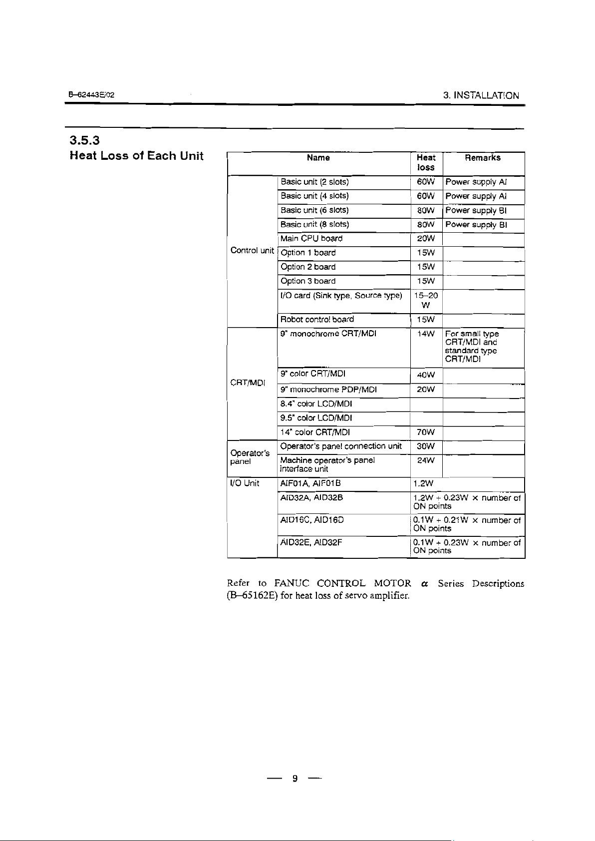
3.53
Heat Loss of Each Unit
Name Heat
Basic unit (2 slots)
Basic unit (4 slots)
Basic unit (6 slots)
Basic unit (8 slots)
Main CPU board
Contfol unit Option 1 board
Option 2 board
Option 3 board
I/O card (Sink type, Source type) 15-20
control board
Robot
monochrome CRT/MD1
9”
CRT/MD1 ’
Operator’s
panel
l/O Unit
9” color CRT/MD1
9” monochrome PDP/MDi 2ow
8.4” color LCD/MD1
9.5” color LCD/MD1
14” color CRT/MD1 7ow
Operator’s panel connection unit
I
Machine operator’s panel 24W
interface unit
AIFOIA, AIFOI B
AID32A, AID328
AID1 6C, AID1 60
AlD32E, AlD32F
3. INSTAUATION
loss
60W
60W Power supply Al
80W Power supply BI
80W Power supply BI
2ow
15w
l5W
Remarks
Power supply Al
15w
W
15w
14W For small type
CRT/MD1 and
standard type
CRT/MD1
4ow
3ow
1.2w
1.2W + 0.23W x number of
points
ON
0.1 W + 0.21 W x number of
ON points
0.1 W + 0.23W x number of
ON points
Refer to FANUC CONTROL MOTOR a Series Descriptions
(E345162E) for heat loss of servo amplifier.
- 9 -
Page 16
3. INSTALLATION .
562443uo2
36
iSTALLING THE
HEAT EXCHANGER
3.6.1
Cooling Fin A/B/C
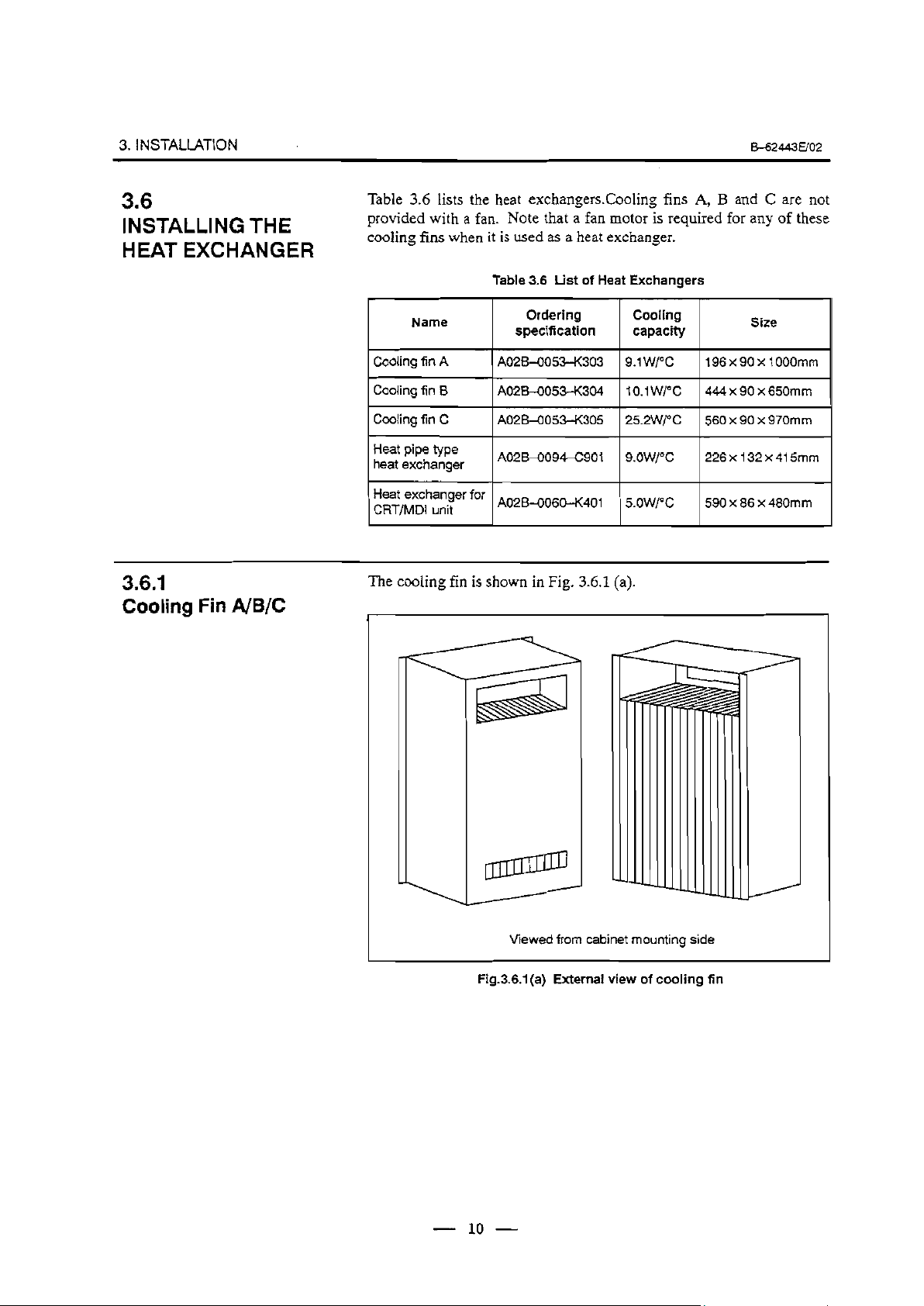
Table 3.6 lists the heat exchangers.Cooling fins A, B and C are not
provided with a fan. Note that a fan motor is required for any of these
cooling fins when it is used as a heat exchanger.
Table 3.6 List of Heat Exchangers
Name
Cooling fin A
Cooling fin B A02B-O053-K304
Cooling fin C A02B-O0533<305
Heat pipe type
heat exchanger
I Heat exchanger for
CRT/MD1 unit
The
cooling fin is shown in Fig. 3.6.1 (a).
Ordering
specification
A02B-0053-K303 9.1 W/“C
A02B-0094-C901
AO2BqO603<401
Cooling
capacity
196x90x1OOOmm
1o.1w/oc
25.2W/“C
9.OW/OC 226xl32x415mm
5.OWl”C
444 x 90 x 650mm
560 x 90 x 970mm
590 x 86 x 480mm
Size
Viewed from cabinet mounting side
Fig.3.6.l(a) External view of cooling fin
10
Page 17
B-62443WO2
3. INSTALlATlON
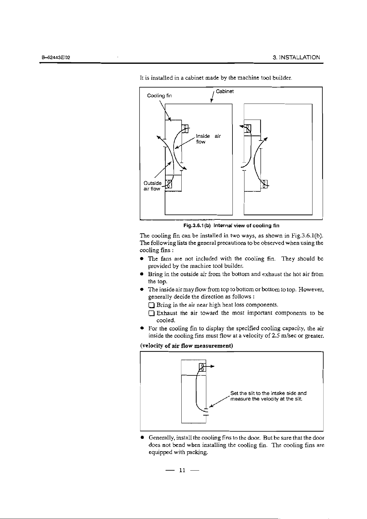
It is installed in a cabinet made by the machine tool builder.
Cooling fin
Inside
fiow
Cabinet
ou
air
Fig.3.6.1 (b) Internal view of cooling fin
The cooling fin can be installed in two ways, as shown in Fig.3.6.l(b).
The following lists the general precautions to be observed when using the
cooling fins :
The fans are not included with the cooling fin. They should be
provided by the machine tool builder.
Bring in the outside air from the bottom and exhaust the hot air from
the top.
The inside air may flow from top to bottom or bottom to top. However,
generally decide the direction as follows :
0
Bring in the air near high heat loss components.
0 Exhaust the air toward the most important components to be
cooled.
For the cooling fin to display the specified cooling capacity, the air
inside the cooling fins must flow at a velocity of 2.5 m/set or greater.
(velocity of air flow measurement)
Set the slit to the intake side and
measure the velocity at the slit.
l Generally, install the cooling fins to the door. But be sure that the door
does not bend when installing the cooling fin. The cooling fins are
equipped with packing.
- 11 -
Page 18
3. INSTALLATION .
562443uo2
1 External dimensions 1
Fan mounting
Mounting metal for
cooling fins (sheet met-
al about 3mm thick).
AM4
mounting
screw
cooling fins
4
PANEL CUT DRAWING
;
for
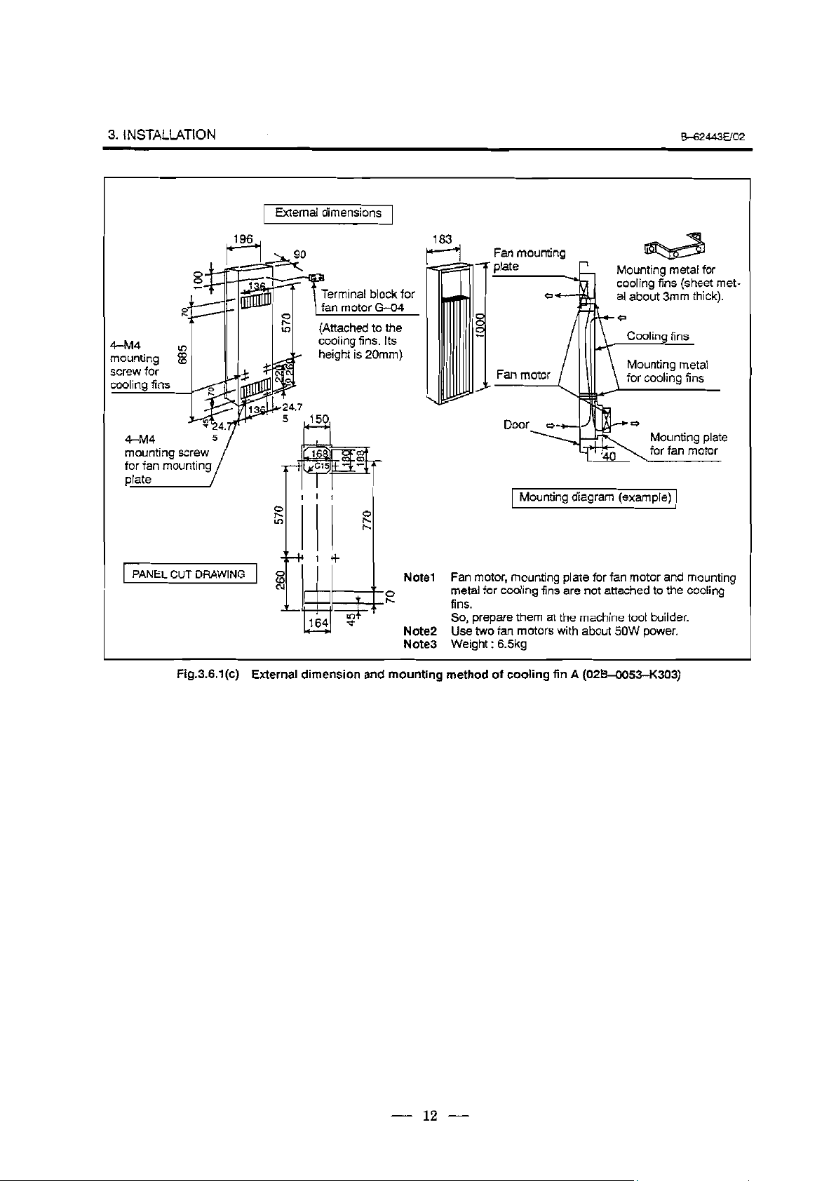
Fig.3.6.l(c)
II I I I
0
s;
cooling fins. Its
height is 20mm)
(Mounting diagram (example)
0
k
/l/l I
I I+
g
cv
:
ILuLl :I
164 %
w
External dimension and mounting method of cooling fin A (0254053-K303)
Note1
E
Note2
Note3 Weight
Fan motor, mounting plate for fan motor and mounting
metal for cooling fins are not attached to the cooling
fins.
So, prepare them at the machine tool builder.
Use two fan motors with about 5OW power.
: 6.5kg
1
- 12 -
Page 19
B42443uo2
3. INSTALLATION
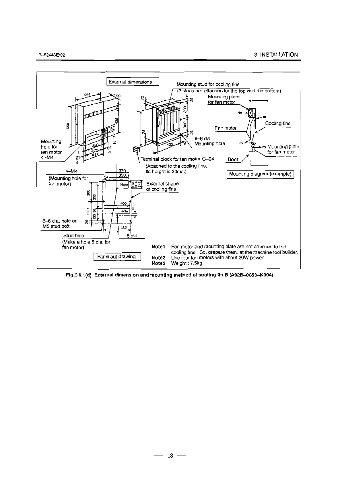
(Make a hole 5 dia. for
fan motor)
t
Panel cut drawing
c
External dimensions
Mounting stud for cooling fins
Note1
Note2
Note3 Weight
Fan motor and mounting plate are not attached to the
cooling fins. So, prepare them, at the machine tool builder.
Use four fan motors with about 20W power.
: 7.5kg
Mounting diagram (example)
.
Fig.3.6.l(d) External dimension and mounting method of cooling fin 6 (A02B405WC304)
- 13 -
Page 20
3. INSTALLATION .
BG2443E/O2
0
H
P
&M4
Mounti--
m olor
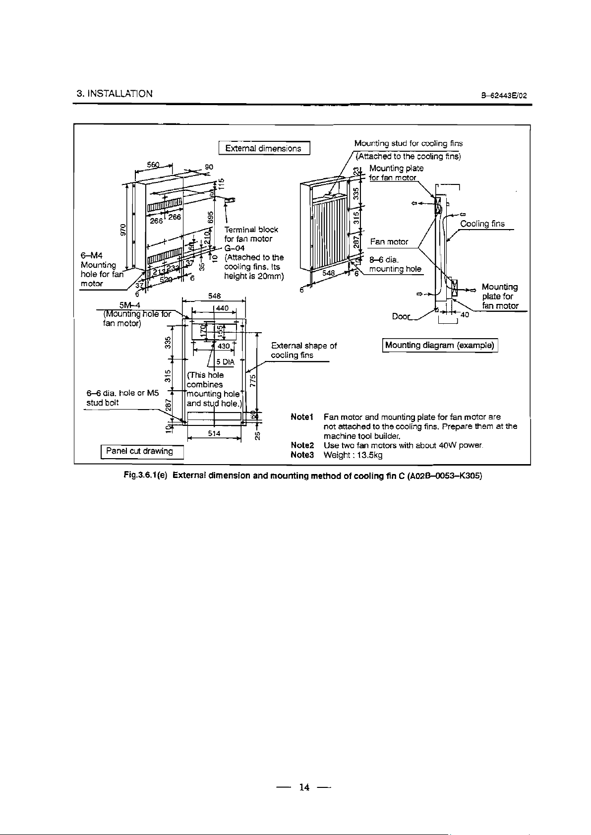
6-6 dia. hole or M5
stud bolt
Panel cut drawing 1
I
I
c
External dimensions
.
P
Terminal block
for fan motor
HE-04
(Attached to the
__
._
cooling fins. Its
height is 20mm)
548 I
.
External shape of
cooling fins
Note1 Fan motor ar Id mounting plate for fan motor ar
not attached
machine tool
Note2 Use two fan
Note3 Weight
unting stud for cooling
MO
/(Attached
to the cooling fins)
Mounting plate
for fan motor
an motor /
F
Ezkg hole
1 Mounting diagram (example)
to the cooling fins. Prepare them
bl uilder.
motors‘ with about 40W power.
: 13.5kg
fins
1
+-a
Cooling fin
S
1
l e
at the
Fig.3.6.l(e) External dimension and mounting method of cooling fin C (A02B4053-K305)
- 14 -
Page 21
b62443uo2
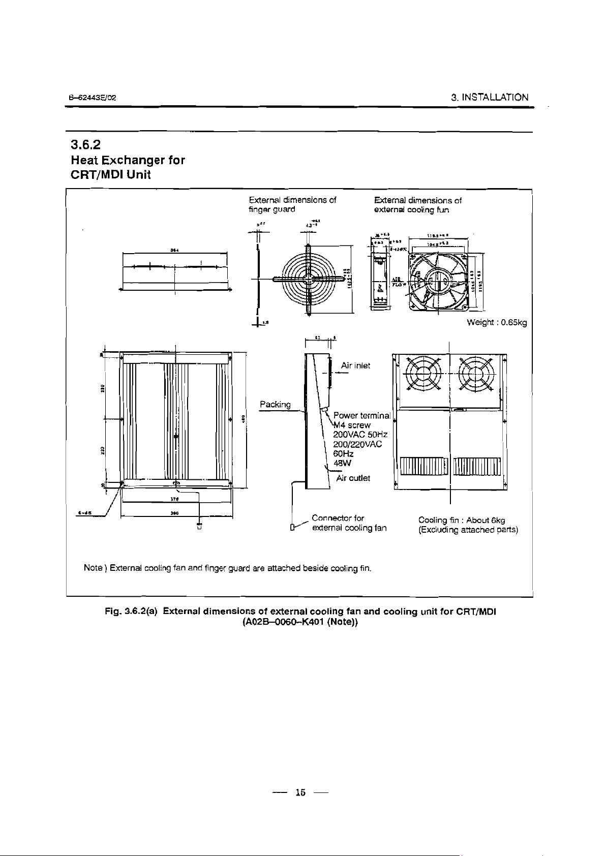
3.6.2
Heat Exchanger for
CRT/MD1 Unit
3. INSTALLATION
External dimensions of
finger guard
s*’
+rl
43”
-It-
External dimensions of
external cooling fun
Weight : 0.65kg
37a
I
396
Note
) External cooling fan and finger guard are attached beside cooling fin.
Fig. 3.6.2(a) External dimensions of external cooling fan and cooling unit for CRT/MD1
(A02B-O060-K401 (Note))
Connector for
k
external cooling fan
Cooling fin
(Excluding attached parts)
: About 6kg
15
Page 22
3. INSTALDWON .
8 Outside Inside
Heat exchanger
Air outlet -
&624436/02
I-
body of
exchanger
Prepare
mounting
screws and
mounting panel
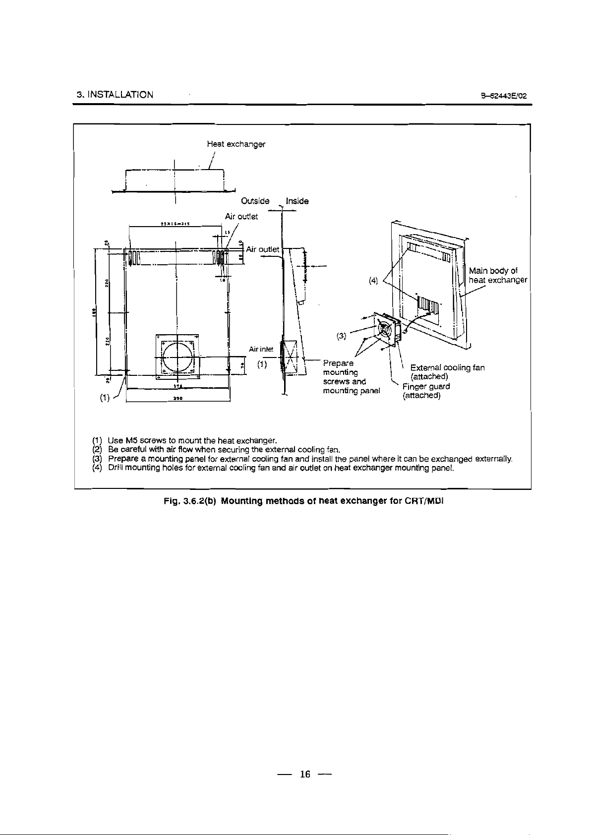
(1)
Use M5 screws to mount the heat exchanger.
(2)
Be careful with air flow when securing the external cooling fan.
Prepare a mounting panel for external cooling fan and install the panel where it can be exchanged externally.
(3)
(4)
Drill mounting holes for external cooling fan and air outlet on heat exchanger mounting panel.
Fig. 3.6.2(b) Mounting methods of heat exchanger for CRT/MD1
. 1
t External cooling fan
I
\ (attached)
Finger guard
(attached)
- 16 -
Page 23
B42443EiO2
3. INSTALLATION
Horizontal type CRT/MD1 only
L Inside
f’ -
f
,.L outs
1
‘ide
Horizontal type CRT/MDI and
machine operator’s panel
Side view
CRT/MD1
I
Heat exchanger
Min
t-7
Top view
-tt
I
I
I
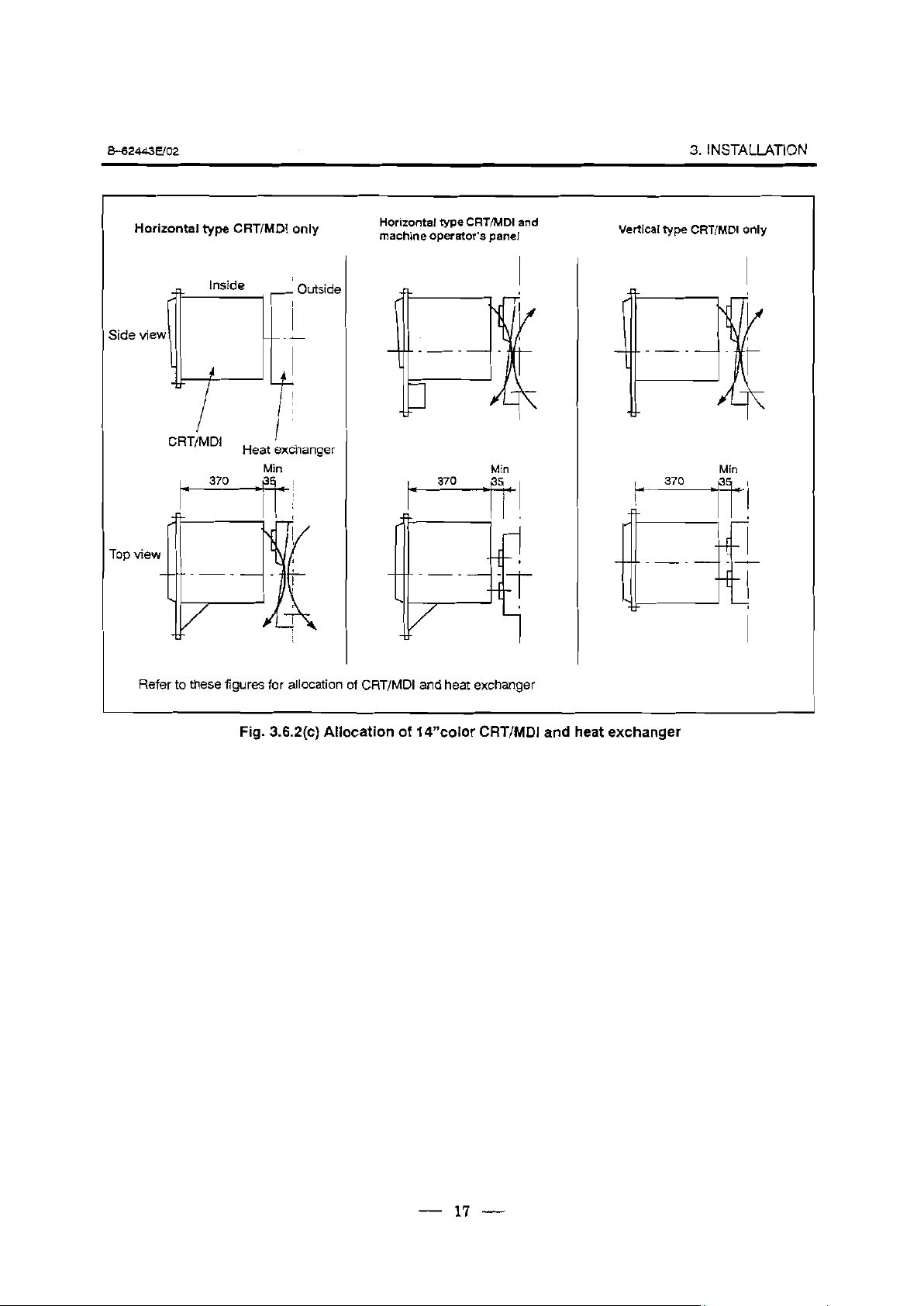
Refer to these figures for allocation of CRT/MD1 and heat exchanger
Min
Vertical type CRT/MD1 only
Min
Fig. 3.6.2(c) Allocation of 14”color CRT/MDl and heat exchanger
- 17 -
Page 24

3. INSTALLATION .
3.6.3
The Heat Pipe Type Heat
Exchanger
B-62443uoz
3.6.3.1
Installation
Specifications
The heat pipe type heat exchanger is used for cooling the airtight cabinet
of small sized electronic devices.
It is a compact, lightweight, and
heat-efficient unit. Because the fan is built-in, it is used simply by
installing it, performing the “panel cut’ operation.
I
Fan
specifications
Weight (kg)
Color
Installation format
Cooling ability (w/“C)
L
Voltage (V)
Frequency (Hz)
1 Rating current (A)
Rating input (W)
1 Installation type in board
9 (50Hz when operating)
200VAC
50
0.28
28
4
Munsell signal N 1.5
60
0.24
26
Order specifications 1 Heat exchanger A02B-O094-C901 1
Remarks
A filter is installed on the outside air inhalation side.
The installation board thickness is the standard 1.6 t.
When a fan motor and filter are necessary for maintenance, prepare
them separately.
Fan motor specifications
A90L=0001”219#A
Filter specifications
A250-0689-X004
If the heat exchanger is installed near the CRT, screen distortion may
occur due to magnetic flux leakage from the fan motor.
18
Page 25
8-62443EJo2
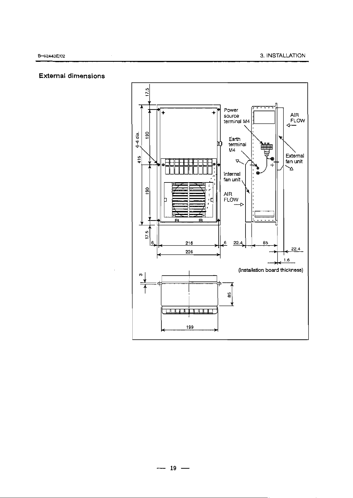
External dimensions
-
-
L
-
Power
source
terminal M4
Earth
: terminal
M4
Internal
fan unit
3.iNSTALLATION
AIR
FLOW
\
\
External
Fan unit
b
AIR
FLOW
,
-
-
226
P
PI
1
__----
L
22.
-A-
(Installation board thickness)
85
-4
4 1.6
22.4
- 19 -
Page 26
3. INSTALLATION .
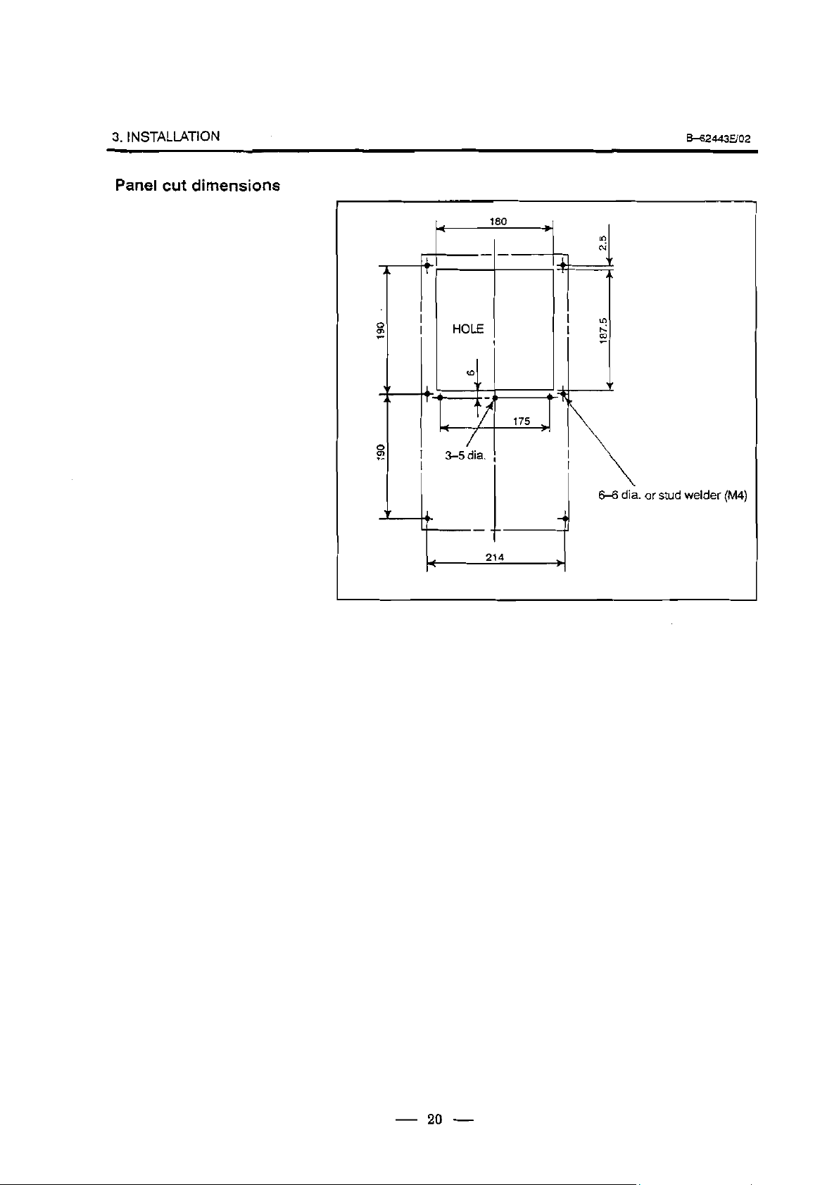
Panel cut dimensions
&-62443E/o2
180
I
. or stud
welder
uw
- 20 -
Page 27
&62443u02
3.lNSTALlATiON
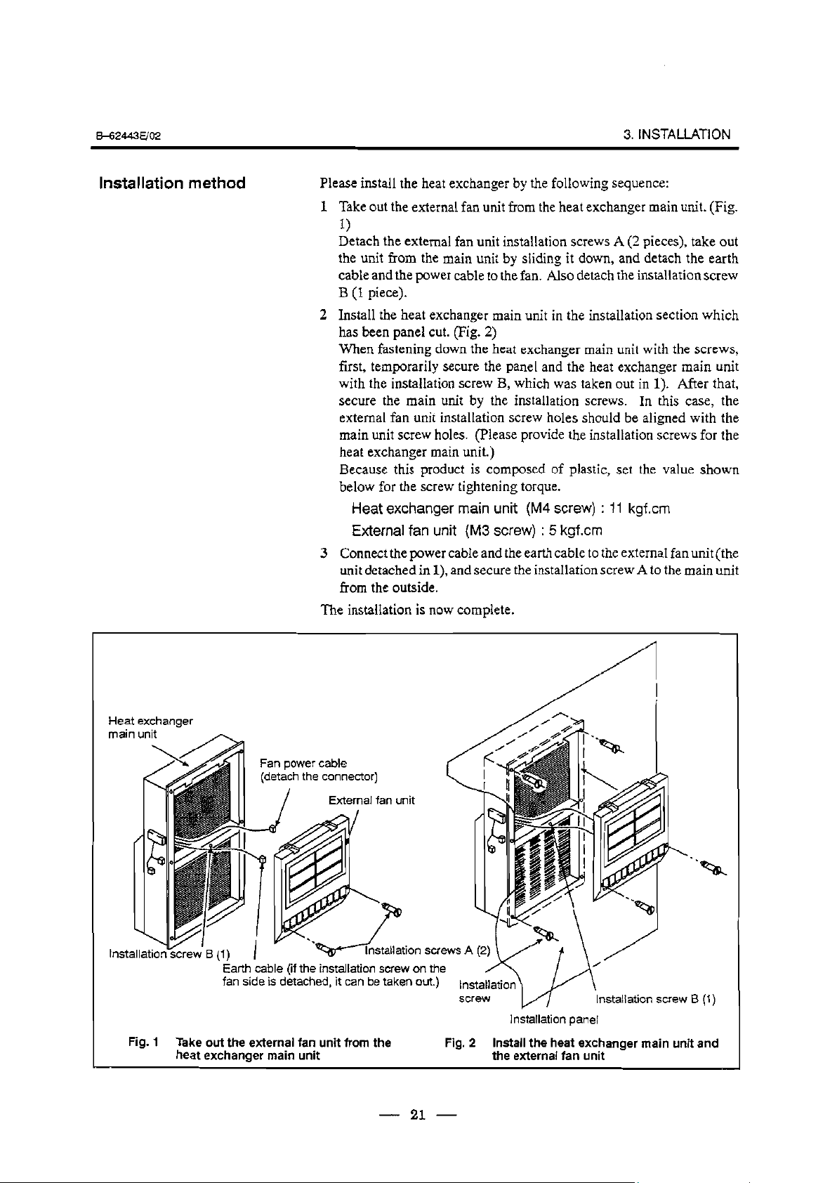
Installation method
Please install the heat exchanger by the following sequence:
1 Take out the external fan unit from the heat exchanger main unit. (Fig.
1)
Detach the external fan unit installation screws A (2 pieces), take out
the unit from the main unit by sliding it down, and detach the earth
cable and the power cable to the fan. Also detach the installation screw
B (1 piece).
2 Install the heat exchanger main unit in the installation section which
has been panel cut. (Fig. 2)
When fastening down the heat exchanger main unit with the screws,
first, temporarily secure the panel and the heat exchanger main unit
with the installation screw B, which was taken out in 1). After that,
secure the main unit by the installation screws. In this case, the
external fan unit installation screw holes should be aligned with the
main unit screw holes. (Please provide the installation screws for the
heat exchanger main unit.)
Because this product is composed of plastic, set the value shown
below for the screw tightening torque.
Heat exchanger main unit (M4 screw) : 11 kgf.cm
External fan unit (M3 screw) : 5 kgf.cm
3 Connect the power cable and the earth cable to the external fan unit (the
unit detached in l), and secure the installation screw A to the main unit
from the outside.
The installation is now complete.
Fig. 1
Fan power cable
(detach the connector)
Earth cable (if the installation screw on the
fan side is detached, it can be taken out.)
Take out the external fan unit from the
heat exchanger main unit
- 21 -
Installation screw B (1)
1 nstallation panel
Fig. 2 Install the heat exchanger main unit and
the external fan unit
Page 28
3. INSTALLATION .
37
A’CTION AGAINST
NOISE
3.7.1
Separating Signal
Lines
B-62443uo2
The
CNC has been steadily reduced in size using surface-mount and
custom LSI technologies for electronic components. The CNC also is
designed to be protected from external noise. However, it is difficult to
measure the level and frequency of noise quantitatively, and noise has
many uncertain factors. It is important to prevent both noise from being
generated and generated noise from being introduced into the CNC. This
precaution improves the stability of the CNC machine tool system.
The CNC component units are often installed close to the parts generating
noise in the power magnetics cabinet. Possible noise sources into the
CNC are capacitive
couplin
g,
electromagnetic induction, and ground
loops.
When designing the power magnetics cabinet, guard against noise in the
machine as described in the following section.
-~
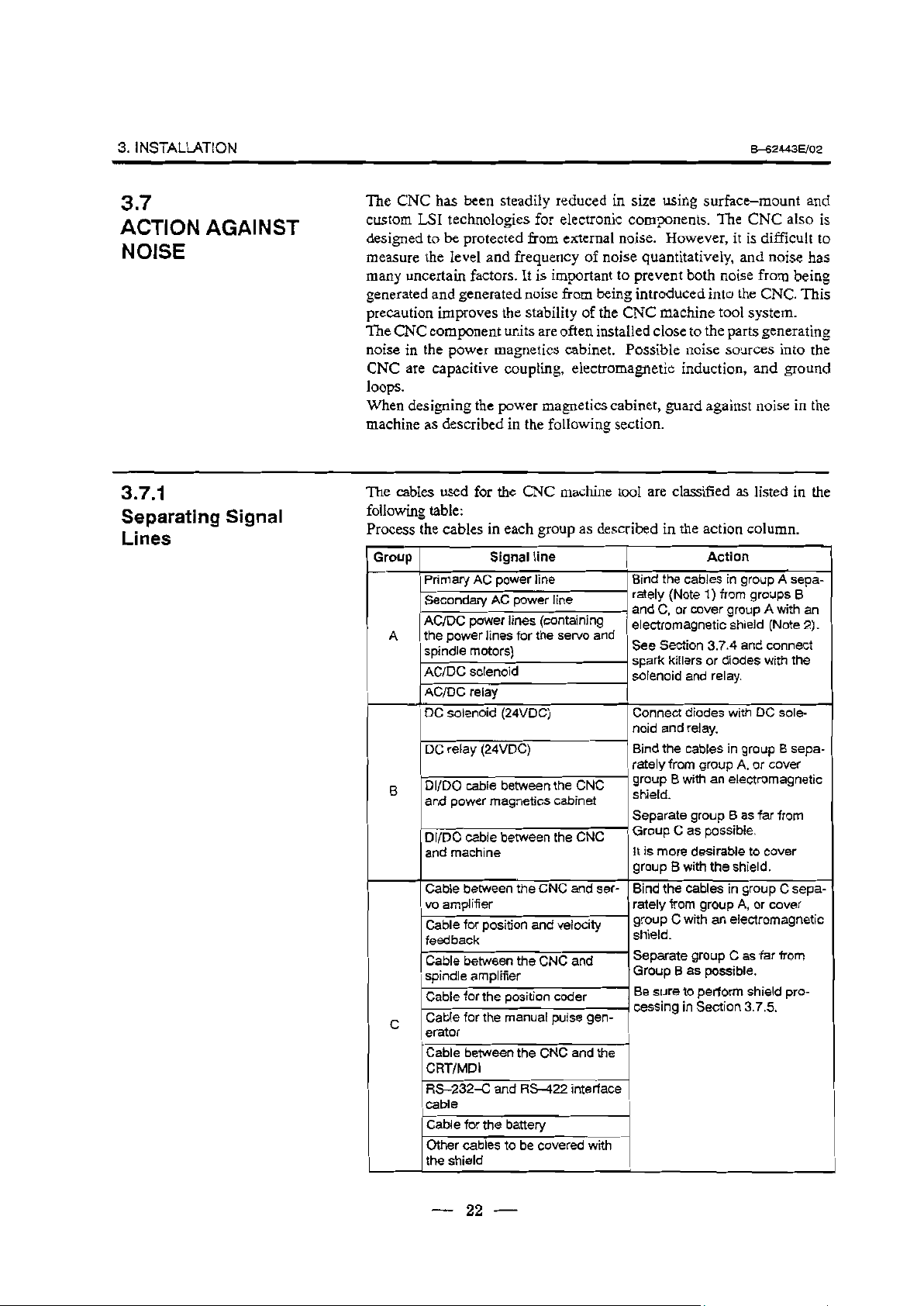
The cables used for the CNC machine tool are classified as listed in the
following table:
Process the cables in each group as described in the action column.
‘0°F) 1
I
Primary AC power line
Secondary AC power line
AC/DC power lines (containing
A the power lines for the sewo and
spindle motors)
AC/DC solenoid
AC/DC relay
DC solenoid (24VDC)
DC relay (24VDC)
Dl/DO cable between the CNC
B
and power magnet& cabinet
Dl/DO cable
and machine
Cable between the CNC and ser-
Signal line
between the CNC
vo amplifier
Cable for position and velocity
feedback
Cable between the CNC and
spindle amplifier
Cable for the position coder
Cable for the manual
C
erator
Cable between the CNC and the
CRT/MD1
RS-232-C and RS-422 interface
cable
Cable for the
Other cables to be covered with
the shield
battery
pulse gen-
I
Bind
rately (Note 1) from groups B
Action
the cables in group A sepa-
. and C, or cover group A with an
electromagnetic shield (Note 2).
See Section 3.7.4 and connect
l spark killers or diodes with the
solenoid and relay.
Connect diodes with DC sole-
noid and relay.
Bind the cables in group B
rately from group A, or cover
1 group B with an electromagnetic
shield.
Separate group B as far from
’ Group C as possible.
It is more desirable to cover
group B with the shield.
Bind the cables in
rately from group A, or cover
group C sepa-
’ group C with an electromagnetic
shield.
Separate group C as far from
Group B as possible.
Be sure to perform shield pro-
cessing in Section 3.7.5.
_
sepa-
22
Page 29
&62443E/o2
3. INSTALLATION
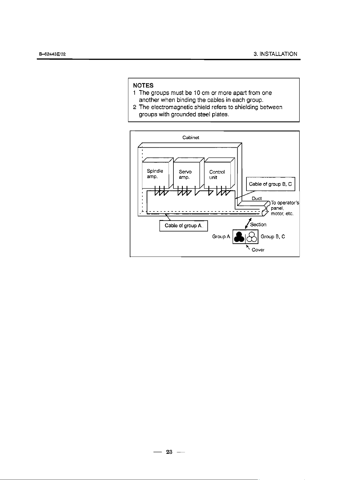
NOTES
1 The groups must be 10 cm or more apart from one
another when binding the cables in each group.
2 The electromagnetic shield refers to shielding between
groups with grounded steel plates.
Cabinet
amp.
I
I
I
I
~.~~_~_~~_~_____~____~__~_~__~___ _
/ /
amp.
unit
C&e of group B, C
Duct
ATo operator
(vl &pan&l
b
‘\ Cover
I
mot& etc.
- 23 -
Page 30
3. INSTALLATION .
8_62443E/o2
3.7.2
Ground
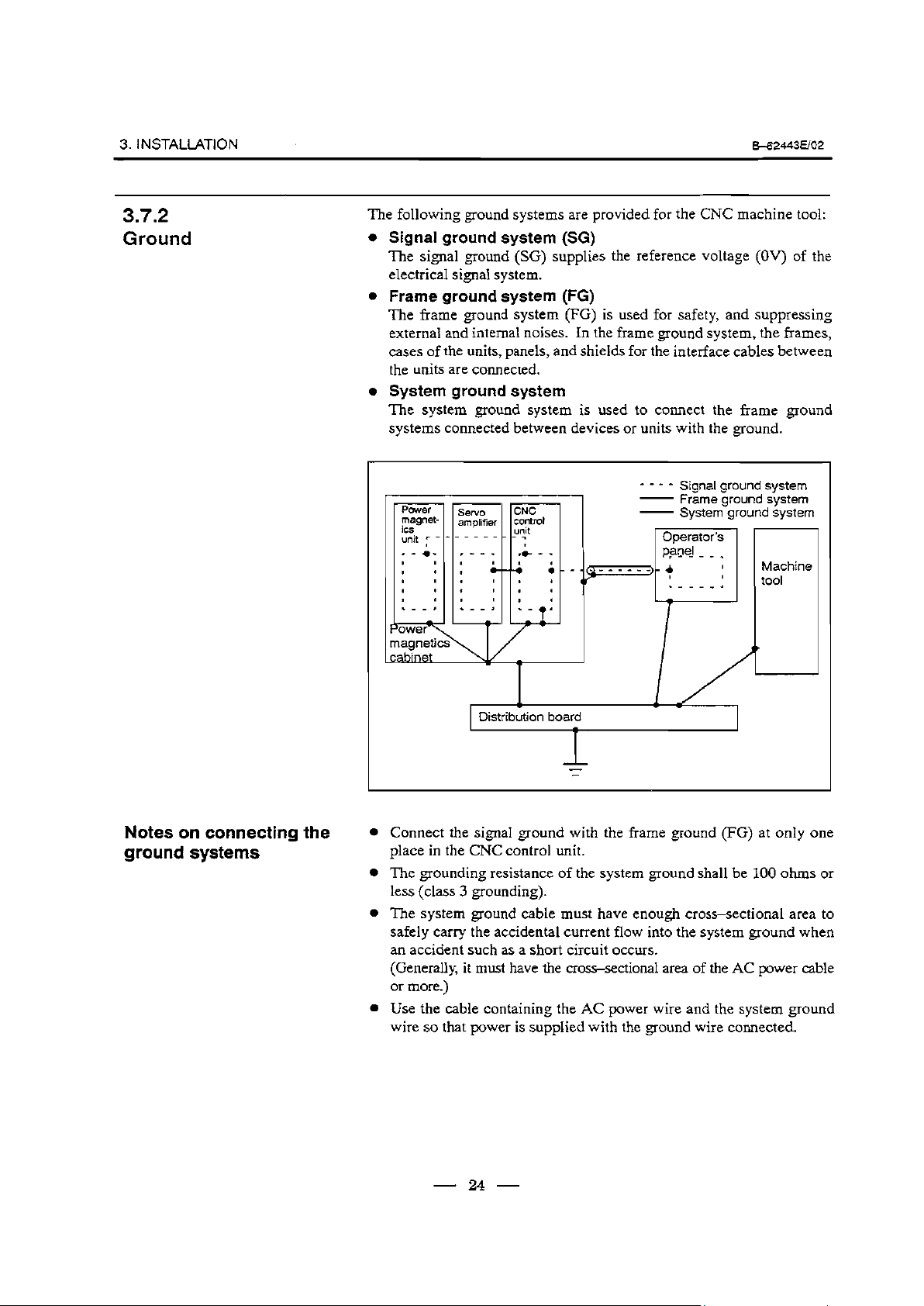
The following ground systems are provided for the CNC machine tool:
l Signal ground system (SG)
The signal ground (SG) supplies the reference voltage (OV) of the
electrical signal system.
l Frame ground system (FG)
The frame ground system (FG) is used for safety, and suppressing
external and internal noises. In the frame ground system, the frames,
cases of the units, panels, and shields for the interface cables between
the units are connected.
l System ground system
The system ground system is used to connect the frame ground
systems connected between devices or units with the ground.
----
Signal ground system
POWM
magnet-
its
unit r -
- Frame
- System ground system
Operator’s
PFCe_l_ _ _
.rr--4
ground system
.
I
Machine
I
tool
Notes on connecting the
ground systems
D&rib&on board
I
l Connect the signal ground with the frame ground (FG) at only one
place in the CNC control unit.
The grounding resistance of the system ground shall be 100 ohms or
l
less (class 3 grounding).
l The system ground cable must have enough cross-sectional area to
safely carry the accidental current flow into the system ground when
an accident such as a short circuit occurs.
(Generally, it must have the cross-sectional area of the AC power cable
or more.)
Use the cable containing the AC power wire and the system ground
l
wire so that power is supplied with the ground wire connected.
- 24 -
Page 31

6-62443ED2
3. INSTALlATlON
3.7.3
Connecting the
Ground (SG) of
Control Unit
Signal
the
Connect the 0 V line of the
ground plate of the cabinet
The SG terminal is located
control unit.
Control unit
electronic circuit in the contro1 unit with the
via the signal ground (SG) terminal.
on the printed circuit board at the rear of the
Ground cable
\
- 25 -
Page 32

3. INSTALLATION .
8-62443uo2
3.7.4
Noise Suppressor
Notes on selecting the
spark killer
The AC/DC solenoid and relay are used in the power magnetics cabinet.
A high pulse voltage is caused by coil inductance when these devices are
turned on or off.
This pulse voltage induced through the cable causes the electronic circuits
to be disturbed.
Use a spark killer consisting of a resistor and capacitor in series. This
type of spark killer is called a CR spark killer.(Use it under AC)
(A varistor is useful in clamping the peak voltage of the pulse voltage,
but cannot suppress the sudden rise of the pulse voltage. FANUC
therefore recommends a CR spark killer.)
The reference capacitance and resistance of the spark killer shall
conform to the following based on the current (I (A)) and DC
resistance of the stationary coil:
1) Resistance (R)
2) Capacitance(C) : ---
I : Current at stationary state of the coil
: Equivalent DC resistance of the coil
12
IO
12
20
(fiJ9
Equivalent circuit of the spark killer
AC
relay
-
*
--II
1 Mount the noise eliminator near a motor or a relay coil.
Note) Use a CR-type noise eliminator. Varistor-type noise eliminators
Diode (used for direct-current circuits)
Y
/(
Spark killer
clamp the peak pulse voltage but cannot suppress a sharp
rising edge.
Use a diode which can withstand a
voltage up to two times the applied
--6-L
Spark killer
[
26
Page 33

M2443UO2
3.7.5
Cable Clamp and
Shield Processing
3. INSTALLATION
The
CNC cables that require shielding should be clamped by the method
shown below. This cable clamp treatment is for both cable support and
proper grounding of the shield. To insure stable CNC system operation,
follow this cable clamp method.
Partially peel out the sheath and expose the shield. Push and clamp by
the plate metal fittings for clamp at the part. The ground plate must be
made by the machine tool builder, and set as follows :
Ground plate
rJ
- 27 -
Fig.3.7.5(a) Cable clamp (1)
Page 34

3. INSTALLATION .
H2443E/O2
Machine side
installation
board
Ground plate
Fig. 3.7.5(b) Cable clamp (2)
Prepare ground plate like the following figure.
Hole for securing metal fitting clamp
Mount screw hole
Fig. 3.7.5(c) Ground plate
For the ground plate, use a metal plate of 2 mm or thicker, which surface
is plated with nickel.
28
Page 35

&62443UO2
3. INSTALlATlON
Fig. 3.7.5(d) Ground plate holes
(Reference) Outer drawings of metal fittings for clamp.
I _ Max.55mm
. .
Fig. 3.7.5(e) Outer drawings of metal fittings for clamp
Ordering specification for metal fittings for clamp
A02B-O0834301(5 pieces)
- 29 -
17mm
Page 36

3. INSTALLATION .
38
CbNTRoL UNIT
B-62443Efo2
3.8.1
Configuration and
Installation of the
Control Unit
Printed circuit boards are mounted in a rack equipped with several slots.
There are three types of printed circuit boards depending on the models
as shown in Fig.3.8.1 (a), Fig.3.8.1 (b) and Fig.3.8.1 (c).
Option
Basic system
Main POWCW
CPU s”PPb
Fig.3.8.1 (a) Configuration of Control Unit (Series 16, Series 160)
30
Page 37

w2443Em
3. INSTALLATION
I .,
board
I
I
CNC CPU
ka;& i&_
trod
Spindle l/F
CRT/M01
(Graphic)
i/O
Link
PMGfW
RS432-C
x2
Power
supply unit
C
H
DI/DO
(40/40)
(W56)
(1 w72)
Basic system
SUPPW
unit
- _ - _ _
Main Power
CPU =Jw
I/O
Fig.3.8.2 (b) Configuration of Control Unit (Series 16, Series 18)
31
Page 38

3. INSTALLATION 3
6-62443uo2
Option Basic system
Main Power
CPU =Pfw
2 slot
3 slot
4 slot
6 slot
Fig 3.8.1 (c) Configuration of Control Unit (Series 18, Series 180)
32
Page 39

562443Em
3. INSTALLATION
The rack consists of a plastic box, fan motors and a backplane PCB. Since
the rack is provided with built-in fan motors, it does not require the
external air flow conditions described in Section 3.5. The air comes into
the rack from the bottom and goes out through the fan motor, which is
located on the top of the rack. Space as shown in Fig. 3.7.1 must be
reserved not to disturb the air flow (111, m)
The backplane PCB, which is located on the rear side of the rack,
interconnects the PCBs installed in the rack.
AIR FLOW
50
t
f
33
Page 40

3. INSTALLATION .
B=62443E/OZ
3.8.2
Battery for Memory Backup
Part programs, offset data, and system parameters are stored in CMOS
memory in the control unit. The power to the CMOS memory is backed
up by a lithium battery mounted on the front panel of the control unit. The
above data is not lost even when the main battery goes dead. The backup
battery is mounted on the control unit at shipping. This battery can
maintain the contents of memory for about a year.
When the voltage of the battery becomes low, alarm message “BAT’
blinks on the CRT display and the battery alarm signal is output to the
PMC. When this alarm is displayed, replace the battery as soon as
possible. In general, the battery can be replaced within one or two weeks,
however, this depends on the system configuration.
If the voltage of the battery becomes any lower, memory can no longer
be backed up. Turning on the power to the control unit in this state causes
system alarm 910 (SRAM parity alarm) to occur because the contents of
memory are lost. Clear the entire memory and reenter data after replacing
the battery.
The power to the control unit must be turned on when the battery is
replaced. If the battery is disconnected when the power is turned off, the
contents of memory are lost.
Observe the following precautions for lithium batteries:
Note
If an unspecified battery is used, it may explode.
Replace the battery only with the specified battery
l A0250200-K102 for power supply Al and BI.
l A02Eb0177.K106 for power supply C.
Dispose of used batteries as follows:
a
Small quantities
Discharge the batteries and dispose of them as ordinary nonflammable
garbage.
0
Large quantities
Consult FANUC.
34
Page 41

w2443uo2
Replacing the Battery
Procedure for replacing the battery
3. INSTALlA7-ION
1 Use a lithium battery (ordering drawing number: AO2EO200--K102)
2 Turn on the power of CNC.
3 Remove the battery case from the front panel of the power supply
unit. The case can be removed easily by holding the top and bottom of
it and pulling.
4 Remove the connector from the battery.
5 Replace the battery and reconnect the connector.
6 Install the battery case.
7 Turn off the Dower of CNC.
Power
SUPPlY
unit
Battery
unit H
4
Battery
Front panel of
Power supply unit
35
Page 42

3. INSTALIATION .
B=62443E/O2
39
&ABLE LEAD-IN
DIAGRAM
Following diagram shows the grid of connector location.
Control board may not have all connectors as shown above.
For actual connector layout of each board, please see the connector layout
diagrams next page or later.
72 7
0 cl 0 cl cl
2.7
I I I
-4
52 ' 60 ' 52 ' 60 r
I
Fig. 3.9(a) Cable lead-in diagram
12.7
_L
f
172
Unit : mm
1
36
Page 43

b62443EJO2
Connector layout of
power supply unit
Power supply unit Al and
BI
3. INSTALLATION
n-r-7
-l
1 I
I I
CP2,3
380
37
\ .
CPS, 6
c
\
F3 F4
.
80
Unit
: mm
Page 44

3. INSTALLATION .
Connector layout of I/O
card (Power supply unit
C is integrated)
I/O
8_624wE/o2
POS. 1
El
Function
1
HIGH SPEED DI
(RIGHT)
2 DIGITAL OUTPUT 1 D>l
(LEFT)
3 DIGITAL
4 24V OUTPUT
5 24V OUTPUT
6 BAITERY
7 DIGITAL INPUT 1
8 DIGITAL INPUT 2
OUTPUT 2 Do-2 c55
(RIGHT)
(LEFT)
Abr. no
HDI
DC OUT CPlB 000
DC IN CPlA 000
DI-1 c50 50 000
01-2 c51 50
Connector No. of I/O card
pins
JA5
C54 50 0
50 00
A B C
0 0
000
0 0
(RIGHT)
9 DIGITAL INPUT 3
(LEFT)
10 DIGITAL INPUT 4
NO. OF I/O ON I/O CARD
38
01-3 C52 20
014 c53 20
NOTE) MARK 0 SHOWS THAT
THE CONNECTOR IS
MOUNTED.
0
0
Page 45

H2443UO2
Connector layout of
main CPU board
(Series
16/l 60 MAIN-A)
3. INSTALLATION
Function
LED INDICATORS
CRT DISPLAY
MDI
SERIAL PORT 1
SERIAL PORT 2
MPG
SERIAL I/O UNK
SERIAL SPINDLE
ANALOG OUT
APC BATTERY
SERVO AMP 1
LJ l10\/01/
SERVO AMP
SERVO AMP 3
Upper iine
marking
STATUS/ALARM
CRT
MDI
R232- 1
R232-2
MPG
IOLlNK
SPDL-1
A-OUT1
APCBAT
AMP 1
2
AMP 2
AMP 3
Lower line
marking
JAl
JA2
JDSA
JDSB
JA3
JDlA
JA7A
JA8A
JA4A
JVl
JV2
JV3
SERVO AMP
PULSE CODER 1
PULSE CODER 2
PULSE CODER 3
PULSE CODER
LINEAR SCALE 1
LINEAR SCALE 2
LINEAR SCALE 3
LINEAR SCALE
4
4
4
AMP 4
ENCl
ENC2
ENC3
ENC4
SCALE 1 ’
SCALE 2
SCALE 3
4
SCALE
JV4
JFl
JF2
JF3
JF4
JF21
JF22
JF23
JF24
39
Page 46

3. INSTALLATION .
Connector layout of
main CPU board
(MAIN-B)
H2443EJO2
POS. 1
Function
clclocl
clclcl
2
3
4
5
6
LED INDICATORS
CRT DISPLAY
MD!
SERIAL PORT 1
SERIAL PORT 2
MPG
SERIAL I/O LINK
SERIAL SPINDLE
ANALOG OUT
APC BATERY
SERVO AMP 1
SERVO AMP 2
SERVO AMP 3
SERVO AMP
SERVO AMP5
SERVO AMP6
LINEAR SCALE1
marking
STATUS/ALARM
CRT
MD1
R232- 1
R232-2
MPG
IOLINK
SPDL-1
A-OUT1
APCBAT
AMP 1
(SERVOI)
AMP 2
(SERV02)
AMP 3
(SERV03)
4
AMP 4
(SERV04)
AMP1
(SERVOS)
AMP2
(SERVOG)
SCALE 1
Upper line
Lower line
marking
JAI
JA2
JD5A
JDSB
JA3
JDIA
JA7A
JA8A
JA4A
JSlA
JS2A
JS3A
JSBA
JSSA
JF2
JF2l
L
- 40 -
LINEAR SCALE2
LINEAR SCALE3
LINEAR SCALE4
SERVOCHECK
SCALE2
SCALE3
SCALE4
SV-CHK
JF22
JF23
JF24
JA26
Page 47

k62443UO2
Connector layout of
main CPU board
(Series
18, Series 180
MAIN-A)
Function
3. INSTALLATION
Marks on connector
UPPer
Lower
LED INDICATORS
CRT DISPLAY CRT
I
MDI MDI
~ SERIAL PORT 1 R232-1
SERIAL PORT
PMG MPG
SERIAL l/O UNK
SERIAL SPINDLE SPDL-1
ANALOG OUTPUT A-OUT1
SERVO AMP 1 AMP1
STATUS/ALARM
2
R232-2 JDSB
IOLINK
JAl
JA2
JDSA
JA3
JDlA
JA7A
JA8A
JSlA
41
SERVO AMP
SERVO AMP 3 AMP3
SERVO AMP
LINEAR SCALE 1 SCALE 1
LINEAR SCALE
LINEAR SCALE
LINEAR SCALE
2
4 AMP4
AMP2
2
SCALE2
3 SCALE3
4 SCALE4
JS2A
JS3A
JS4A
JF2l
JF22
JF23
JF24
Page 48

3. INSTALLATION .
Connector layout of
option-lA board
With only graphic
function
E62443uo2
With
communication
function
Iclclcl
cKJcl
Function
LED INDICATORS
CRT DISPLAY
RS232C PORT3
RS422 PORT1 R422- 1
marking marking
STATUS/ALARM
CRT
R232-3
Upper line Lower line
JAI
JDSC
JDGA
- 42 -
Page 49

B-62443Em
Option-2 board
(Series 16/l 60
MAIN-A SPEC.)
3. INSTALLATION
10
11
12
cluao
clucl
Function
LED INDICATORS
HIGH SPEED DI HDI
ANALOG INPUT
SERIAL SPINDLE
ANALOG OUTPUT
APC BATT-ERY
SERVO AMP 5
SERVO AMP 6
SERVO AMP 7
marking
STATUS/ALARM
A-IN
SPDL-2
A-OUT2
APCBAT JA4B
AMP5
AMP6
AMP7
Upper line
Lower line
marking
JA5
JA6
JA7B
JA8B
JV5
JV6
JV7
13
14
15
16
17
18
19
20
21
SERVO AMP 8
PULSE CODER 5
PULSE CODER 6
PULSE CODER 7
PULSE CODER 8
LINEAR SCALE 5
LINEAR SCALE 6
LINEAR SCALE 7
LINEAR SCALE 8
AMP8
ENC5
ENC6
ENC7
ENC8
SCALE 5 JF25
SCALE 6
SCALE 7
SCALE 8
JV8
JF5
JF6
JF7
JF8
JF26
JF27
JF28
- 43 -
Page 50

3. I NSTAUATIO N
Connector layout of
option
(Series
2 board
16/l 60 MAIN-B
SPEC., Series 18/l 80)
.
H24436/02
Series 161160
(6 axes)
2
I
Series 18/l 80
El
0000
000
Function
LED INDICATORS
HIGH SPEED
ANALOG INPUT
SERIAL SPINDLE
ANALOG OUTPUT
APC BA-TTERY
SERVO AMP 1
Marks on
Upper
STATUS ALARM
HDI
A-IN JA6
SPDL-2
A-OUT2
APCBAT JA4B
AMP1
Connector
Lower
JA5
JA7B
JA8B
JSlA-2
44
AMP 2
SERVO
AMP 3
SERVO
SERVO AMP
SERVO AMP 5
AMP 6
SERVO
LINEAR SCALE
SCALE 2
LINEAR
LINEAR SCALE
SCALE
LINEAR
SERVOCHECK
AMP2
AMP3 JS3A-2
4
AMP4
AMP5
AMP6 JS6A-2
SCALE1 JFZl-2
1
SCALE2 JF22-2
3 SCALE3 JF23-2
SCALE4 JF24-2
4
SV-CHK JA26
JS2A-2
JS4A-2
JS5A-2
Page 51

H2443E/O2
Connector layout of
option-3 board
3. INSTALLATION
POS.
For CAP function
With PMC-RC
function
I
Function
LED INDICATORS
SERIAL I/O UNK lOLINK
Upper line Lower line
marking
STATUS ALARM
marking
JDlA
- 45 -
Page 52

3. INSTALLATION .
Connector layout of i/O
Card
B=62443E/OZ
I/O Card A
Dl/DO=40/40
0000
or0
/
I/O Card B
DI/DO=80/56
I/O Card C
DI/DO=104/?2
I/O
rl
R
01
I/O Card D
DI/DO=156/120
l/O
Function Marking E:iyeFtor
(RIGHT)
OUTPUT 1 DO-1
(CENTER)
OUTPUT 2 DO-2
(LEFT)
OUTPUT 3
(RIGHT)
INPUT 1
(CENTER)
INPUT 2
(LEFT)
INPUT 5
DO-3 C58
DI-1
01-2
01-5
c54
c55
c50
c51
C56
I
I 1
I
(RIGHT)
3 01-3 C52
INPUT
(CENTER)
INPUT 4 01-4
(LEFT)
6 01-6 c57
4
INPUT
c53
- 46 -
Page 53

Eb62443uo2
Connector layout of
loader control board
(Series
16/i 60 MAIN-A
SPEC.)
3. HfJSTALlATION
.
Function
POS. 1
2
3
4
10
11
14
LED INDICATOR
- BRAKE DRIVE
OUTPUT
/ EMERGENCY STOP ESP CNPW
CONTROL
- OPERATOR’S
PANEL INTERFACE
\ WORKPIECE FEEDER
SERIAL I/O UNK
SERVOCHECK CHECK
APC BATTERY APCBAT
- MEMORY CARD
SERVO AMP 1
SERVO AMP 2
SERVO AMP 3
SERVO AMP
4
STATUS/ALARM
BRAKE
TP
WF
IOLNK
AMP1
AMP2
AMP3 JV3
AMP4
CNBK
CNTP
CNWF
JDlA
JA8C
JA4
CNMC
JVl
JV2
JV4
15
16
- 47 -
- PULSE CODER
- DI/DO
ENC CRFl
RDIO
CRMl
Page 54

3. INSTALLATION .
Connector layout of
loader control board
(Series 16/l 60 MAIN-B
SPEC., Series 18/l 80)
Function
Marks on
Upper
8_62443E/o2
Connector
Lower
POS. 1
2
3
4
10
11
12
13
14
LED INDICATOR
- BRAKE DRIVE
OUTPUT
/ EMERGENCY STOP ESP
CONTROL
- OPERATOR’S
PANEL INTER
FACE
L-
’ WORKPiECE FEEDER
SERIAL I/O LINK
SERVOCHECK
- MEMORY CARD
SERVO AMP 1
SERVO AMP 2
SERVO AMP 3
SERVO AMP 4
STATUS/ALARM
BRAKE
TP
WF
IOLNK
CHECK JA8C
AMP1
AMP2
AMP3
AMP4
CNBK
CNPW
CNTP
CNWF
JDlA
CNMC
JSlA
JS2A
JS3A
JS4A
15
16
17
18
19
20
21
n
LT
I
- 48 -
- DI/DO
1
RDIO
CRMl
Page 55

B-62443EfO2
Connector layout of
MMC-IV
3. INSTALLATION
POS. 1
2
12
Function
LED INDICATORS
NC VIDEO SIGNAL
INPUT
VIDEO SIGNAL
OUTPUT
SERIAL PORT 1
SERIAL PORT 2
LCD TUNING
FLOPPY DISK DRIVE FDD
0
PARALLEL PORT
EXTENDED
KEYBOARD
Marks on Connector
upper
STATUS
NC CRT
CRT
RS232-1 JD5F
RS232-2
LCD ADJUST
CENTRO JD9
EX KEY JO21
lower
ALARM
JAl B
JAlA
JD5G
JD8
13
14
15
16
FULL KEYBOARD KEYBOARD CD32A
MEMORY CARD
(PCMCIA)
MOUSE MOUSE CD32B
MEN CARD
CNA
- 49 -
Page 56

4. TOTAL CONNECTION .
.:‘.‘..‘.~.‘.~.‘.~.‘.~.~.~.~.~...~.~.~
..‘.‘...‘...‘,‘.‘........f
TOTAL CONNECTION
. . . . . . . . . . . . . .
: ,... .;.._....... . . . . . . . . . :.:.:.:.:‘,.:.:.:.~.:.‘.~.~:.: ..‘............. . , :.,,. .
:::::::::,:~:i:i:.:i:i:::i ye.... :.:.>>:.:.. :.:.:.:.: .,... :;:;:i::.:: ::;:: :,
:.:i:; ;I,: . . . . . . :.:,: :,y..:.:::: .::::::::::.::::,i::,::.:.:.:.:.:: +:.:.
. .:... ,.::. :... ; :... . . . . ..: . . . . . .._...
4
..... .: >:.y :,:.,,:,y. . . . . . . :.:: . . . . . ., ..,.: . . . . . . . . . . . .,.
::.:. .,.,...,*,. .,... .: . . .
,. .,. _: ,.... ..,.. ,._. .: :.:.‘.:.:.:_:.:.,. ,.;_.. . . .;,., ;, ;; .
. . . . . . . .,.. . . . . . . .;, .,l,.,.L,. .,.,. .,.,.,. ,.,._ . . . . .
. .” :.,.:.:.:.:.>:.:.:.: :...:..‘.‘.:.:.:.:.: ,.,.: .,... ‘. :.:.>:.: :, :.,:. . ,+:,:. :.x.:.. ;_.,.,.,.,.: ,.:.:.y. .: :_:.:_: ,,,.: ,,I,>: :.: . .
..:,:., : :.:,: .:,:.:.:,:,:, .: :,,,,,: ,..;:,:,: ,,: ~,,~: .: :.:.::.:.
.:.:.: .,.,. >>:.,.: ;.: . . .
. . ._, . . . ... . .*.:.:.: :‘~.~,:.:.~:.~~.:.:.~.~~.~.... . . . . . .:::; . . . . . .,
. .
. .‘. i.,.: :.: 1.1 :. .:.:.~,.:...‘.:.:.~:.: ::::.:.::: :::.:...:
,.,...,...,.. t _.,., :,. ._. . . . . . .,.,.,.
. . . . . . . .
. . . . . . . . . . . . . :....:.. . . . . . . . . . . . ,_. . . . . . . . . . . . . . . .g. . . . . . . . . . . . . . . . . . . . . . . . . . . . . . . . . . . . !.,.< . . . . . . . . . . . . . . . . . . . . . . . . . . . . . . . . . . . . . . . i . . . . . . . . . . . . . . . . . . . . . .
. . ”
” ‘. . ..‘...‘..
‘.“):t :‘:.:‘:‘:‘:‘:.‘.:,~~:.:.:.,,:,:.~ . . . . . . . :..,-. ..,..., ,.,.. . ...: . . . . . . . . . . . . . . . . . . . . . . . . . . .
..,. :.......:.:. .‘.:. ._.,.;,..._. . . . . >:,>:.: :.:,:,:,:...,.: :::y::::: :...:.:
.,_: ,:,: . ...:. :.... ‘.:+:!v. _...:_ . . . . . . . .._._
,,,,,: : :,.,:, ,,, ,. :,,;,. ,,,,.,., ,.,.,.~,,.,,~ ,.,.,,,,,.,,, .,,,...,,. _,,,, . ~.~.,.,.~.......,.~.,.,. :.:.:.>:.:.:.,.: :...: .,... >:.:.:. .: :‘:.:.:‘>..:.:.,.>: . . . . : . . . . . . . . :. .: :.;: :::y:.:
: :
,.:,. .:...:.:.. ::.v: ./ ,. .>:.> . . . . . . . . . . . _.,.;,.,. .,.;. . . .
.: :.:.>. :...:.:.:...:.‘...:.:.:., ..x.: . . . . . . . . . . . . . . .
. .:,:.,,: :.:...:,:. . . . :::::: ,: :_. :...:..:: ::.::+:. .:.:.:.: : :.>:.:.:.:.:...:.:.: . . . . . :.:: ::::;<:::::, :.~.:.:,:.:.:.‘,....‘,.,.....,.......,.. :. . . ..’
_. ,:. ,., ,. .: $.‘Jq’. : ::: ., . . . . . . . . _:., :.:.:.: . . . . . . .:.:.:.:.~::.:::.;i:i ,:y::>i:; .:,, y.:.:::: :y.: ‘...
. . :., :.:.:.:. ._._.,., ..,...,., . . . . :..;:,.
. .: . . . . . . .._.... . . . . . . ..,.. . . . .‘...‘.‘.‘...‘.‘i....‘.. ‘.‘...*...*.-:.
. . . . . .
:.‘.:.:.~~:.:.~:.:.~.:.:.:...~~~.:.::.~~ .;,. .
..,.,.,_. ..,_ :.,.:.,.:.:, .:,: ~.‘.‘~.~,C~.~.~.‘.~.~.~ . . . . . . . . >>:.:.:.y..:.>,., ,. . .._ .
:.., . . . .._.. ,. .,. . . ,., . . . . . . .
., ..::~i:i:::i:if31:5’:::::::::.:::::::::: :: :.:.: :.: :.:.:.::.>:.:.: :.:.:.:.:.:.;;:.: : ;
.‘.‘.‘.‘.:.:.:.: ..,.. . . . . . . . . . . . . . ..,.:....... . . . . . . . . . ..i..........~.~..:.~:.:.:.:.:.:.:.:.:.:.~:.:.:.::.: :+>..: :y......;........ . .
. . . .
..‘. .“. .‘.‘.‘. . . . : ,:,,,:.:, :.:: :.:.: ::::::::‘::.:
. .
,. . . . . . . . . . . :‘:‘:‘:.:.f:‘:.:‘~~~.~~:.~.:.~:.,.~~~:.:.:..’.’.‘.
..,. :.:.~:.~~.:.:.:...:....:.:.:.~:.~:.:...:.:.’.:...:.:.‘.: . . . .
.‘.:.:.:.::.!.~.:,:,‘,:.:.:. .: ,,... :... . ..,.... ~.~.~,:.:.:,:.:.~ . . . . . . . .;_ ;,:. . . . . . . . . . * . .
.
‘.’
. .:.:.q+:.:.: ‘.:.>:. .:: .,... 3:.
. .,.,._. . . ._.;, ,. . :. ..:.
. .:.:.:.:.:.:.:.~:.:.:.~:.:.:.:.:.... : : :i . . .‘..
:...:.:.~:.:.:.:...~:.~:
. . . . .., ,. . . . . . . . . . . . . . . . . . . . . . . . . . . ,... . . . . . . . . . .
. . . . . . . . . . . . .
.‘.‘.‘.....‘.‘.‘.‘. . . . . . . . . . . . . . . . . . . . . . . . . . . . . . ..a...... . . .._. ,...............,.,.....
.v.:.>:. .~:.‘.,.:.~:.~::.:.~~:.~:,:.~.:.:.:. . . . . . . ..a. .
., _,.: y:::::‘:‘::::::::.: ‘.....’ ‘...‘. . . . . . . .
., 1.1 y: : . :.
.‘.~.‘.x’.‘..>:.‘..... :.:.:.:.:.~.:,.,:...:.:.:.~:.:...:,:.:.:.: . . . . . . . . . . . . . . . . .
.,..._..._., . . .
.‘.‘...’ ..’ . . . .
: ‘. .:y::::::, :.~_.:.....~.~.~;.~; ,.... . . . . ., . .
. . . .‘.‘.‘.:.:.~.:.:.:.:...:.:.:.:.:. ::......,...,..... ,.....:. . .
: ... . ...‘. : .:::. . . . . . .
:.:.: :.:.:.. > ._..... . .
.** . . . . . . . . . . . . . . . . . . . . . . . *... . . . . . . . . . . . . . . . . . . . . . . . .._..................................
. . . . . . . . . . . . . . . . . . . . . . . . . . . . . . . . . :.,‘:.:.:‘:.:.~:......
. . ..‘...S.h. . .
,.
. . . . . . . . . ,....... . . . . . . . . . . . . . . . . . . . . . . . . . . ..~..‘..~.........
. . . . . . . . . . . . . . . . . . . . . . . . . . . . . . . . . . . . . . . . . . . . . . . . . . . . .
. . .
. . . .““‘.:‘:‘:.:.:.:t’:.~~.~~:.‘..~.~.- ..‘.‘.‘...‘.... . . . .
. . . .
. . . . . . . . . . . :.: ,,..,,.. . . . . . :.:.:.:,:, ~:,~~ :.::::: ~,
,..‘. .’ ..‘...‘.‘.‘.‘...‘...‘.. . >:::. . ..‘.... ..,.. .:, ;, .: ,.....:.....: ,:,.::;.i .,., ,:::::.:::::.:,.:.:.: .,.:.:... ,.
.
. . .
. . ..‘...‘.. ........‘, .‘...‘...‘... .....,.Zii..i..,.,.....,., ,,,_ . .
. . . .;. . . . . . :.
.‘.f.‘.~.‘.~.~.~.~.~..,~,~.~ . . .._......
.y.:.:. .,.....,.,... . . . . . . . . . . .,.,. . . . ...,. ._.;,. .;..,. :.:‘~:.:.:.:.:.:.:...: ..y ..,.. . . . . . . .,., . . . . . . . . . . . . . . . . . . ‘.:..
.
. . . . . .._ ,.; :.:. .:,:.:.‘.‘.‘. :. _:,::.,.:,:.
: _.,. ‘.
,.;: :
..:::::
. . . . ..‘.‘... . ;. ::;,
. . . .~.~,~.~..,~,~_..~,... .
. . . . . . . . .: I:.:.:. .,. .: :, ,:: : :: ,::‘,‘:‘:‘::::::.::::‘::.‘.::‘:‘::’:’:::::’:’ : : ,_‘.I ‘,‘.:,:.‘,~,:,:.‘.: :.:.:..,:.
,: :::;: ~, : : :..,‘,“,‘,. .:.:.:.‘.: :. . . ,. .,. .: ..:
.I,
. . . . . . ,. .,: :.: :: ,, j:..::: ,::‘i’;::.:: i;::ii:i’,:i.i:::i:i’:: :;:i:;::..
.,...:,
. . . . . . . . . . .‘....‘.f’.‘.
.
. . . . . . . . . . . . . . . . ,.:.::. . . . . . . . . :.:.~:.:.:,:.:.“.‘..:
. . . . . . . . . . . . . . . . . . . . . . . . . . . . .‘.‘.‘. :.
,. . . . . . .
. . . . . . . . . . . . . .
.,., . .:.., :_ ,.
:... ,’ ‘, . ‘. ,. ‘.. ‘k. ‘.‘.... ,‘. .‘.’ ‘.
:
.‘.’ ‘.‘.> . . . . . . >. ,.>,. :. :. .‘...‘.‘.‘. ,.,.; ‘.:.:.,.:.: y., :.:. .:.: >:.: ..,.>::. .,.:.:.‘+,.: :
.~,~::::,
,‘.‘,. : ‘.‘,... ~;;:;:;: ;:_. :;:.;: ,’ :, ; :: . . . . . ::. .:
..: ‘.‘.Z :.:.‘.:.:.:.:.:.~.:.:. ,.. ..,,.::...
. . . . . . ::.:.:.;+: :., ,., ,. . .
‘:.:.:.::.‘.:.‘.‘..‘..... ‘.‘.‘.y.:.:.; .:...:...::.:.:::::.::
t.. ‘. .‘.‘.‘. .., . . ., ,,
.,I..,.,.. . . . . ::.:: :.:...::...:.:...
.
.
B42443Elo2
. ..,..., .,
. . . . . . ,.....,.,., ,.. .“::‘::::::‘::::.:‘::::’ :y::: c::::::::;: $:.:‘. ::cj:::zy::
. .,._. ,.. .,. . . .,.. ,. ., .,. ;,. _.
:.:.: ““‘.“:::,:::. .:.:.:. :‘,““:‘:,:‘::i:::::I:
. . . . . . . . . :: ‘. .’
.
.:.:.:,:.:: :,:.: ::.::::I$ ‘: ::: : :: .,...,
.‘.‘. . . . . ...‘. .:.::::y,.:::.:: :: :: :~::::::::_:
. ,,; .‘:.f: ,..,. .,.::,: I;.:: 1::: : ,.,.,.; .,._...,.,... . . .
,., ,..., ,...;..,., :.,.:.>:.,: ..:.: ‘.‘.‘.. ‘. .:.>,. ::.
. ..‘.‘..
.‘. :: ..‘. :.
.I. . . . . :.: :.:.:::,::::::::‘..‘.’
‘. ..::. . . . . . ..:.:.. . . . . . . .
.., .
,. _.
. . . . . . :. ;‘:.
. .;
: : . . . .
. .
..:.:c.‘> .:
50
Page 57

B-62443uo2
4. TOTAL CONNECTION
41 8
CONTROL UNIT
The Series 16/160 and Series 18/180 support two types of main CPU
boards, MAIN-A and MAIN-B. The overall CNC configuration,
including the specifications of the option 2 board and loader control
board, depends on which main CPU board is being used.
This manual refers to the configuration which uses the MAIN-A CPU
board as the MAIN-A specifications, and the configuration which uses
the MAIN-B CPU board as the W-B specifications. The table below
details each configuration.
Series
M/160 16/l 60
MAIN-A MAIN-B
SPEC.
Kind of Main
CPU board Max. 4 sxes Max. 6 sxes Max. 4 sxes
Kind of Op- MAIN-A MAIN-0 SPEC. MAIN-A
tion
2 board SPECI Max. 6 axes
Kind of Load- MAIN-A SPEC, MAIN-B SPEC. MAIN-B SPEC. MAIN-B SPEC.
er
control
board
MAIN-A MA! N-B MAIN-A MAIN-B
Max. 4 axes (Sub CPU) Max. 4 axes
(Sub CPU) Max. 2 axes (Sub CPU)
Max. 4 axes (Add. axes)
(Add. axes)
Series
SPEC.
Series
18/l 80
MAIN-A
SPEC.
SPECl
Series
18/l 80
MAIN-B
SPEC.
Max. 6 sxes
Not used
Interface with Type-~
sew0 amp. (Connectable to (Unconnectable (Unconnectable (Unconnectable
C series ampii- to C series am-
fier) plifier) plifier) plifier)
Type-B Type-8 Type-8
1 to C series am- to C series am-
51
Page 58

4.TOTAL CONNECTION .
Series 16/l 60 TOTAL CONNECTION DIAGRAM (MAIN-A SPEC.)
TO JAlB OF iNMC KHEX PPIC IS USED
AC 2OOV-240V POWER
ti USE +24V hHEN 9*' ~O.CRT IS USED.
t362443UO2
(SE 7)
cWr(JAl )
MDI(JA2 )
R232-l(JD5A)
C
R232-2(JD5B)
0
N
T
R
0
L
U
N
I
T
MPG(JA3 )
IOLINK(JDlA)
(SE 6)
A-OUTl(JA8A)
FANUC I/O LINK
+ANALoGouTPur
FOR TOOL DRIVE
1 I
FROM JAl OF OPTION 1 BOARD
EmmENCYsmP
POSITION CODER
*
BRAKER
I
SPDL-l(JA7A)
BATKRYFOR
AEsoLuTEFc
APCBAT(JA4A)
AMPl(Jv1)
ENCl (JFl )
SchLEl (JF21)
- 52 -
SERVOMOTOR
i
;
.
,
I
:
Page 59

e42443Efo2
4. TOTAL CONNECTION
ENC2(JF2) gjr
SCALE2(JF22) Q
Aii(Jv3) g@;
Em(JF3) m
SCM(JF23) B#
MlP4(Jv4) $8
Ezm(JF4) bu
SCALE4(JF24) BI
C
0
N
T
OPTION 2 BOARD
R
0
t
i KONNECTION CONTORMS TO 1ST AXIS) i
,
1
P
3ND AXIS SERVO A,PwmR/Fc/LI~ SCALE:
i KOb@iEXXON CONFQEWS To IST AXIS) :
,
*
1
.--~---~~~~~~~~~~~~.~~~~~~~~~~~~~~~~--~~~~~~~~~~~~~~~~~~~~~~~~~~
AXIS SERVO AMI?/Plomupc/LI~~ SCALE I
: 4TH
8
i KONNECI’ION CONF’ORMS To 1ST AXIS) :
0
,
8
.--~*--~~~~~~~~~~~~~~~~~~~~__-~~~~~~~~~~~~~~~~.~~~~~~~~~~~~~~~.~~.
1 REMOTE BlTFFER OR DNCl (RS422)
- RFMUK BUFFEZ (RS232C)
k~ ANAUG OUTEVI’ FOR TOOL DRIVE
0
I
1
I
1
8
U
N
I
T
IOLIM(JDlA) g@
R422-2 (JD6B) ’
FAN’X I/O LINK
b
(CONNECM)N CONF’ORMS To 1ST AXIS) j
To
I/O WIT MODEL A (FOR PK-RC)
53
Page 60

4. TOTAL CONNECTION .
I/O CARD
WE 6)
C
0
N
T
R
0
L
U
N
I
T
HDI (JASB)
IDl(C54)
00-2(m)
co-3(C58)
DI-1 (CSO)
DI-2(C51)
DI-3(C52)
DI-4(C53)
DI-5(C56)
DI-6(C57)
HIGH SPEED SKIP SIGNAL
. . . . . . . . . . . . . . . . . . . . . . . . . . . . . . . . . . .
Do 40 PoINTs
Do 40 POINTS
DO 40 PmTS
DI 40 POIllJTs
DI 40 POINTS
DI 12 POINTS
DI 12 POINTS
DI 40 POIlvTs
DI 12 F’OINTS i
i
i
i
:+
i
i
i
i
.
6-62443E/O2
MAGmICs CABINET
MMc-Ivcpu
KEYBOARD(CD32A
MOUSE (CD328
FROM JAl OF MAIN CPU
b-
b-
TO CNl OF CRT OR LCD UNIT
A] RS232C I/O DEVICE
% FWPPY DISK
Uid JD8 UNIT PWl
’
%
FULLKEYBOARD
%
MOUSE
HJSED FOR DEVELOPMENT OF AN APPLICATION.
CANNtYI’ BE USED FOR ACML RUNNING.
f+-- AClOOV
b
1
,
- 54 -
Page 61

B42443EJo2
4.TOTALCONNECTION
C
0
N
T
R
0
L
U
N
t
T
CHECK (JASC)
ESP (mew)
pilypl (JSlA)
AMP2 (JSZA)
AMP3( JS3A)
AMP4( JS4A)
I
/
d
.
.
.
.
.
.
. . . . . _._..-.s_..-...a...e ..__ ____.._...__..I
I
I
6
~NNECUONTOTHE i i
SERvVOAWcoNFoREvfs~i i i
THAT OF 1ST AXIS OF
MAIN CPU BOARD.
.
.
.
.
.
.
.
.
.
.
.
.
.
.
.
.
.
.
.
.
.
.
.
.
.
.
.
.
. .
.
.
.
.
.
.-...-.----.-.- . . . . . . . . .
_-.--..._I . . . . . . . ..I.....
.
..__..I *__._ . . . . . . . . _._I_ . . . . . . . _..._._ . .._.
.
..I. -
. . .
.
.
.
i III/
.
.
.
.
.
.
.
.
.
.
.
.
.
LOADER BODY
I
I I
.
.
.
.
.
.
.
.
.
.
.
.
.
AClOOV
1ST AXIS
SEW0
CODE3
3RD Ax
SERVO
MOTOR
t
a 4THAx
1 SEW0
c
-i
MOTOR
OVERTRAVEL LIlYIT
IS
.IS
TP mw
IOLINK( JDlA)
Ill
FANUC I/O LINK
&j-Gq Et&::
ADDITIONAL I/O ’
55
.
.-._.-.I-..-.-__._.-.-.-.-...-...-..- . . . . m.._..w-..-_-.-.
.~._...~_.._~_.__.. *- ._.. _...- . ..I... -..--.--..--..---*--
Page 62

4. TOTAL CONNECTION .
Series 16/l 60/l 8/l 80 TOTAL CONNECTION DIAGRAM (MAIN-B SPEC.)
To JAlB OF WC h?IH \WlC IS USED
L
AC 2OOV-24OV FWER
RS232C I/O DEVICE
C
0
N
7
R
0
L
642443uo2
U
N
IOLINK( JDlA) B
I
T
(SE 6)
A-OUTl(JA8A) @j---- ANAL0G OU’mn’
FANUC I/O LINK
FOR TOOL DRIVE -
BA7TERY FOR
PULSE CODER
CXlA ‘IBl CX2A JXlA
2ND SPINME
CODER
A
1 ,
56
PULSE
1ST AXIS
LINEAR SCALE
Page 63

Bd244%!02 4. TOTAL CONNECTION
AiW(JS2A) @I
SCALE2(JF22) g
AW3(JS3A) aa
SCALE3(JF23) &
AMP4( JS4A) @j
SCALE4(JF24) b
AMP5 (JSSA) c 1
APll?6(JSGA) ’ a
SV-CNJM) fB- SERVO CHECK (5, 6 AXIS)
I
f 2bD AXIS SERVO Ai’P/M0I’OWPC/LI~EdR SCALE ;
1
1 KONNECI’ION CONFMMS To 1ST AXIS)
I
~--~~~~~~~~~~~~~~~_~__~~~~~_~~~_~~~~~_~~~~~~~~~~~~~--~~~~~~~~~~~
; 3bD AXIS SERVO AMP/MoToR/WLINEAR SCALE :
: KONPKT’ION ORMS ‘I0 IST AXIS)
:---_________-__________________________~~~~~~~~~~~---~~~______~
’ 4TH AXIS SERVO AMP/MoToR/Fc/LINEui SCALE :
;---___________________-________________~~~~~---~~~-~~~~~~_____~
: 5TH AXIS SERVO Aiimwpc
I
: KONNECI’ION C0NF0m To 1ST AXIS)
;---__________________-_~_____-_________~~~.~~~~~~~~~~~~.~.~~~__~
,
t 6TH AXIS SERVO AMP/WIWF’C
I
: (CoNNEcfION CONEQRMS To 1ST AXIS)
‘--~_~._~_~.~.~~~~_.~~~~~~~~~~~~~~~~.~~~~~~~~~
OPTION 1 BOARD
(SE 7)
CRT(JA1 ) I
R422-1 (JD6A) @B
C
R232-3(JD5C) BB
0
N
T
R
OmON 2 E?oARD
0
(SEE 7)
L
A-OUT2 (JA8B)
A-IN( JA6 )
U
N
I
T
HDI(JAS )
SPDL-2 (JA’7B)
mAT(
”
MERY FOR ABSOLUTE
JAW @-+=-j PULSE CODER (FOR LINEAR SCALE)
b
L J
if+-SERVO CHECK (5TI-I AND 6TH AXIS)
)---~~~~~~~~~~~~~~~~~~~~~~_~~~~~~~~~~~~--~~~~----~~~--~-~------~----~~
t
1 SUB 1ST AXIS SERVO AMP/MWOR/PC/LINEAEi SCALE:
i
~~---_______________--_________________~~~~~~~--~~~~~~-~-~~~~~~~~~~~~~~
~----~-_~-__~~-~_~___-_
--m-__
~~_~~_.~~_______~~_~~.~~~~~~~.~~~~~~~~~----------~--.~~~~.
KONNECI’ION C0NFWMS To 1ST AXIS)
i
i
i
t
i
I
8
i
A
‘IQ CN2 OF CRT
UNIT (ONLY MEN CAP II IS
(Series 161160 ONLY)
Rf9Wl-E BUFFER OR DNCl
REMOTE BUFFER (RS232C
-__.__-w-_-e___,,:
USED)
(RS422)
WIG OUTPUT FOR TOOL DRIVE
ANALOG I/O
HIGH SPEED DI
COWECI’ION CONF’ORltS To WT OF MAIN CPU
BOARD
(coNNEcTrION CONFW8 ‘I0 MAIN 1ST AXIS>
i
SUB 2ND AXIS SERVO AMPomom~I~ SCALE :
KONNEtXION coNFoRMs To
----______~~____~_~_~~~~~~~~~~~~~~~~~~--~~~~------~~---~~-~~~~~-~~-~~
SUB 3RD AXIS SERVO AMP/MoToR/pc/LI~ SCALE :
WNNECI’ION CONFUR% TO MAIN 1ST AXIS)
_~-_~______._~~_____~~~~~~~~~~~~~~~~~~~~~~~~----~~~~~~~
SUB 4TH AXIS SERVO AMPmurwPC/LI~i-~m-
K0NNECTION CONFORMS TO MAIN 1ST AXIS)
--SuwrH AXIS SERVO AMP/imoR/PC
: KONNECI’ION CONFORMS TO MN 1ST AXIS)
; SUB 6TH AXIS SERVO AMP/iWTWPC
;
__.____________._______---___-_____------~~~~~~~-~~~~~--~~_~
________________________-_______________------~
KONNE~ION CONFW% To MAIN 1ST AXIS)
----~__-~~~~~-~~~_~_~~~~~~~~~~~.~~~~~~~~~~~~~~~ ,,,,,,.,,,,,,,,,----,’
MAIN 1ST AXIS)
i
i
i
8
,
i
t
,
i
FANUC I/O LINK
To I/O UNIT MODEL A (FOR PWRC)
- 57 -
Page 64

4. TOTAL CONNECTION .
I/O CARD
(SEE 6)
C
HDI(JA5B) @j
0
N
T
R
0
L
U
N
I
Do-l(C54) JE
m-2 (C55) ‘13
DO-3(C58) 60
DI-l(C50) 10
DI-2(C51) i]O
DI-3(C52) 10
DI=4(C53) 11
DI-5(C56) 10
DI-6(C57) ]E
T
HIGH-SPEED SKIP SIGXAL
. ..s__.._..__ . . . . . . a-..-- . . . . . . . . ---.
.
; Do 40 POINTS
; Do 40 mm
: Do 40 Ftxm
.
: DI 40 POIMS
; DI 40 POINTS
: DI 12 POINTS
.
; DI 12 POINTS
: DI 40 FQINTS
: DI 12 FQINTS
.
.
. .._._.s...- . . ..I s...-..--...a-.e . . . .
!
i
i
b+
i
i
i
i
i
BG2443UO2
iblEoIJETICs CABIrn
MMC-IV CPU
NC CRT( JAlB)
CRT( JAlA)
R232-1 (JD5F)
R232-2 (JD5G)
MOUSE (CD32B
FROM JAl OF MAIN CPU
I
c--------- To CNl OF CRT OR LCD UNIT
I
#USED FOR DEVELOPMENT OF AN APPLICATION.
CANNm BE USED FOR ACWL RUNNING.
~1 RS232C I/O DEVICE
“1 PRINTER
:. L
x
MOUSE
/IO-- POWER
- 58 -
Page 65

B-62443uo2
BRAKE (aBK)
AFCEiAT( JAM)
C
0
N
T
R
0
L
APC BATIERY
. . . . . . . -.-.-.-es . . . . . -._ ._..._..--_.._._.
.
.
i SEZRVO AMP coNFam3 i
.
: To THAT OF MAIN
.
XPUEDARD
.
. ..__e.. t..
i
.
.
.
.
.
.
.
.
.
.
4. TOTAL CONNECTION
ET AXIS
*
1 SERVO
,
’ MOTOR
t
2ND AXIS
SERVO
MOTOR
AL PULSE
U
N
I
T
IOLINK(JDlA)
FAMJC I/O LINK
.
.
. sw,LED
.
i _._._..........._.___.__......._..._..._...-_._... ---.-.
4 OPERATOR’S
PANEL FOR
LODER
- 59 -
Page 66

4. TOTAL CONNECTION .
Series 18/l 80 TOTAL CONNECTION DIAGRAM (MAIN-A SPEC.)
8-62443uo2
ACGT’(CP3 ) 5% 1
ON/OFF(CP4 j $Z \
+24V(CP5 ) Z
+24E(CP6 ) SZ
I
MAIN CPU(TYE’E-A)
(SEE 7) I
m(JAl 1 EM
C
0
N
T
R
0
L
U
N
I
T
MDI(JA2 ) g5
R232-l(tlD5A) B5
R232-2(JD5B) &#--
m(JA3 1 Bfl
IOLINK( JDlA)
FROMJAlOF j
MMCBOARD
v
(WHEN MMC IS USED)
(SEE 6)
A-OUT1 (JA8A)
+ANAmOmPuT
c
FOR TOOL DRIVE L
71
I
I
I ,
e
USE +24V hHEN 9” MONO. CRT IS USED.
1
*I RS232C I/O DEVICE
1
AC 2OOV-240V KMER
1
SPDL-1 (JA7A)
JA4A)
JSlA)
BAmY FOR AE%S
PC (LINEAR SCALE)
d5da
POSITION CODER
SERVO MOTOR
PULSE
I J.___J 1ST AXIS
LINEAR SCALE
- 60 -
Page 67

B42443Em2
U
N
I
T
4. TOTAL CONNECTION
N REiWIE BUFFER OR DNCl (RS422)
8 REiWTE BUFFER (RS232C)
ANALOG OUTPUT FOR TCOL DRIVE
To
MAIN CPU BOARD
6V ABSOLUTE PULSE CODER
(FOR LINEAR SACLE)
FANUC I/O LINK
ti
TO I/O UNIT MODEL A (FOR PW-RC)
- 61 -
Page 68

4. TOTAL CONNECTION s
I/O CARD
(SEE 6)
C
0
N
T
R
0
L
u
N
I
T
HDI (JA5B)
m-1 (c54
DO-2(C55
DO-3(C58
DI-1 (C50
DI-2(C51
DI-3(C52
DI-4(C53)
DI-5(C56)
DI-6(W)
MC-iv CPU
NC CKI’( JAlB)
CRT( JAlA)
* tl!a HIGH SPEED SKIP
f
Ii
I
FROM JAl OF MAIN CPU
.I... . . . . . -..........................
Do 40 PoIrn
Do 40 FoIms
Do 40 FcuNTs
DI 40
___~
To CNl OF CRT OR XD UNIT
.
t
. . . . . . . . . . . . . . . . . . . . . . . . . . . . . . .
FOINTS
DI 40 POINTS
DI 12 POINTS
DI 12 POINTS
DI 40 POINTS
DI 12 POINTS
B42443Ejo2
i
i
i
:+
MAc;ivETIC CABINET
i
i
i
i
i
..I...
R232-l(JD5F)
R232-2
KEMOARD(CD32A
MOUSE(CD32B pu
41 RS232C I/O
Mom
I
1
WJSED FOR DJZVELOPMENT OF AN APPLICATION.
CANNOT BE USED FOR ACTUAL RUNNING.
DEVICE
1
1
62
Page 69

B-62443ElO2 4. TOTAL CONNECTION
SERVO CHECK BOARD
RECTIFIER FOR BRAKE EYERGNCY STOP CWIROL
. ..__.-w . . . . ..I. -..-...-I.-- . . . . . . - . . . . . . . - . . ..I.. _-.._.
.
CIRCUIT
Ei%( 24V)
.‘”
C
0
N
T
R
0
L
U
N
I
T
CHECK (JAK)
BRAKE (WK)
AMPl(JSlA)
AMP2(JS2A)
AMI?3( JS3A)
AMP4( JS4A)
SERVO AM0 czoNFoRMs i
To THAT OF 1ST AXIS i
OF MAIN CPU BOARD i
.-.--..-...-..._._.-.-.--..~.-..-~.~.~.-.- ..I.. -.
.
.
.
*
. .
. .
. .
.
.
:
.s.._... .
.
.
.
.
.
: ’
i
i
.
*
.
.
.
.
.
.
.
.
.
.
:
.
.
.
:
.
.
.
.
.
.
.
.
.
.
.
.
.
.
. . . . . . -...I...--*...* ..__._.
UlADER BODY
Ijll
.
.
.
AClOOV
1ST AXIS
SERVO
1
MOTOR
’ 2ND AXIS
=I SERVO
i mrrOR
‘\ SERIAL PULSE
CoDER
” 3RD AXIS
1 SERVO
1 WTOR
4TH AXIS
smvo
MOTOR
OVER TRAVEL LIMIT
/4v
IOLINK( JDlA)
ADDITION& I/()
FANUC
I/O LINK 4 JDlA DI/DO CONFOR
JDlB MING To I/O
24V POWER ___cl
LINK
63
._._ a..--...*..--...- . . . . . . . --...1.-- . . . ..I _.- . . . . . -._...
.
- LOADER
i _....._...__...._.._...._. _ _...
_.._I- . . . . . ---.-_.._- . . . .
Page 70

4. TOTAL CONNECTION .
WHEN POWER SUPPLY C IS USED.
&62443F/02
Psu-I/O BOARD
24V-IN (CPM) 92
24V-OUT(CPlB) 2:
DI-l(C50) [Ip6 i
DI-2(C51) Dcw i.. . . . . . . . _.___._:
DI-3(C52) jGL--_i
DI-4(C53) ~c---_i
MAIN CPU(FS18 MAIN-A)
C
0
N
T
R
0
L
U
N
I
T
~C2OOV
DC 24V POWER SOWE
I
..-_e . ..I _.a._._.
.
. . . . . -.-.-..--._._.._..._- . . . . . -*.._.
ti USE +24V WEN 9” iWNO.CRT IS USED.
.
:+ IYAm-
TICS
.
cAB11Nl?r
RS232C I/O DEVICE
BRAKER
2oov
SPDL- 1 (JA7A)
AMP1 (JSlA)
I_
To 2ND SPINDLE
2oov
POSITION CODDR
”
SERVO MUI’OR
TB2 CX2A JXlA
PULSE
- 64 -
Page 71

E62443ElO2
4. TOTAL CONNECTION
. .
17
‘4
-~~~_~~-_~~~__-_-_-_-~~~~.~~~~~~~~~~~~~~~~~~~~.~~~~~~~~~~~~~~~~,
! lST MS
Im3R SCALE
2ND AXIS SERVO APlP/MoToR/Fc/L11w SCALE /
- 65 -
Page 72

5 POWER SUPPLY UNIT CONNECTION
:.::::..~:.:.....‘,:...~.~~..::.’.~...’
:.~.~,:‘,,,:.~.,.‘.:.~.~.~::.
.:.~~.::‘:‘::..:~~:~~~~~~~:~~~~::~~:~~~~~~~~~~~~~~~~:~:~:~.~~~~~~~~~~~~~~:.~:.:...~~...~.:.~:.:.:..~:~:,:.:~:~~~~~~:~:~:~:.:.:.:.~.:~~.’~::~.:~:~.~:~:~,~.‘.:.~.’.:.::.‘,’.:,:
.,.,._.,~,,,,,~~,,,,~,~,~,,.,
:.::.:.:.::
:.::,:.:.:.::.:.:.:
.,.,.,.........:...:.:.~:.:.:.~.~,.~.~.~.
‘.~...~.............~.~.~.~..
H2443UO2
5
POWER SUPPLY UNIT CONNECTION
‘.%.... ..:... .’ ‘.‘.‘...‘.
~:,.;:;.~. .: ._y.:.: . .
::: :.x.:.:: . . .:+,
.i.:: :, ‘. ._:.:., :..,.,
;,. ., .:,:, y .:.: :::j:.::::. ‘.: ..:. .,.,., .,., ,.,
.
:.:.: .i.::,.::.:.::.y.: : .,.,.,., .
.:.,. . I . . . . . . . . ...‘.....‘.. ‘... ., .., .,.,,.,,,.
. : ‘.‘.‘..... .-....:: ..‘...’ ‘.‘.’ . .._ ;,.;, ,. .;, :.: >‘.:.y.:. .:,:.:.>r :.:.:.:.:,~:.:.:.:,:.: .,.....,.,...,
.‘,‘,‘.:.:.:.:.: :‘:.:,:.‘.‘.‘.‘.‘.‘.’ . . . . .,.,
::::: ::‘:::~::::::::::i:::i:i:i::.~:
::>;.i:::i.;:;:::: ;:;:;:I f:::i’i:i:i:i::::::.:‘:’ ‘.‘....,.
. . . . . . . . . .
. . .
. . . . . . . . . . . . . . . . .:.:,,,:.:.>
. .‘...‘....,‘.‘. .‘. . :..:: ‘...
. , . . , .
.
. . . ...‘.‘.‘. . :::. .‘.‘.....‘.
:.:.:.~:.‘.‘.‘.‘.‘,...:.. . . . . . . . .
.:,I. . . . . . . . ..,. 1: :‘.:“::,:.:.: :,:.:‘:‘:,~.“‘,>~.. .:,
.,.,.., 1.. ,. ‘.‘. . . . ,. . . ..,....... .: :p::: ,: ::‘::,:::::.‘:‘.:::.:: ..,.,: :, :.:: .. :,::.,: : :
.‘.......~..‘.~.......... -.: .: :+:.:>.
. , .
. . . . . . . ..* . . . . . ..;... .: . . . . . . . . . . . .,.,....., . . ,, .,. ,, _, ,,., ,.
,....‘...‘.‘.‘...‘.‘.‘...‘....‘.:.. .‘...‘...‘. .’ ..‘.‘... .‘.
. . . i.,:.-.. .:.~:.-.~.-:......;. ,:.:.:: :.: ,.: :,::.:::::.::.,, .:.:,:.: :.: ,,,, zl:
. .‘.‘.. .....: . . . . ;. . . . .‘.‘.‘.‘,‘.‘.‘.:.:.‘.:.~ . . . : :.:.:.:+....:... ,.. .,, ‘. ,:
:: . ::::. ::. :::::::: 3:: :.: ~:.,.;.,.: .,... :.:.>:.:.
.:.:.: :.: :.:.:.:.:.: :.:.>.., ,.;;,.,. . ,. .
. ..,., . . . . . . . :::::.::::::::::::j:‘:::~~~:.:: : :.:.:.;., : :.:.:.: :...>:.:.:.:...‘.’ .
. :: ‘. ..:. . .’ . . ., +... .,., :) :,:,. : ::‘::::., ::::,;::. : :,:, :>, :;, ,,:::::::: .,:.:, .,, :,: : : :.,,
.,._. . ...,.; .;; .,.,.,.;, 1, ; ;,., ;,.,.
‘.‘. .‘.‘.‘. . . . . .: .,.; :...:.. > ,.,.,.: ,.,.. ,.;..’ :. .: ,.;;: :.,.:...>, . . . ..~...........~. ., .,. .:: . ..‘.‘.‘.”
,, . :, ,:,, . :_. :, y;,.:,:;: :,,:*:.: ‘.:.:.:,:,,.: :::::’ ::‘:&:‘y>, :‘::::.‘:..::~::::.:‘::.‘.:.: :.‘.~:::::.:.::::::::~:.:. ..::.:.:y:.:::::j: ::.::.:.:. .:,:.’ .: ‘.‘.. ‘...... . . .‘.’ :.: : :: y y.‘.‘.‘.‘,‘.‘.‘. . . . .,_ .,.I
. . . . .,., ,:.:,...,.....,.~. .,:: :... :.:,= .:.,.: .:.:.:,:,:... ~:
,. .,.,._ .I.. .:.: . . . . :.:.:.,.>:.,.: :.:.:.>.,
. .., :... . . . . . . . . . . . . . . . . . . . . . . . . . :_
. _...,.. . .
. . ..;i
.:.:.:.:.:,
..,....I....... . . . . . . . . . . . . . . . . . . . . . . ..:.:.:.:.:.~~:.,.~:.:.~:,::::::::::::~,~::::::.:~~::::.:.. . . . . . . . . . . . . . . . . . ‘.‘.‘.‘.‘.‘.‘.‘.‘.‘.:... .:,:.: ..~,~....,....~.~,~,
. ...:.,.>+;: . . . . . . .._..
‘..... .‘.‘.. . . :..:. ‘........... .:.:.:. ,’ . .:, ,.. . . .,...
. ,.I ,.;,. .: ‘.‘.:+:.,: :., J:‘;. . . . . . . . . ..;. :.::... :. .:.+:.. .‘... . :;. .
.., ,.,., ;,. .,.,.. ,.; . . .
..~.~.~.“.‘.%y.:: :.,.:.:A._. >:.:I .:...y . . . . . . . :. . . ..i :.: :.,.‘...‘.,.~:.~~.~.~: .,.,. .,. .,.......,,.. .:.:+. . . . . .
..: :. ,. .,.
. . . . ..A%~.~.- . . :..A.: _,:A:... .,.,.,
,..
.‘..‘. ‘. . . ::+: :. :..... :,..., :;..,:. .:::;..A~. :; . . ..,.i.‘..,‘, . . . . . . .
:_:.: :.. ..:.:.:.>: . . . . . . . . . . . . . . . . . . . . . . . . . . . . . . .
. .5.;. . . . . . :.:.: ;.:.:.:,::.: ?.‘.
. . . . ..,.. .,.~.~.,.~,,.~.,,~,~. . . . . . . .:..... . .~.~.~~~.~~~.,~,.~~~.~.~~~.,.,.~.~.~.~., ; ., ,...,., :::::::y::: :: ::::‘,:‘:..::::::‘:
. . . ..‘. .: : ..:.:. >:,: . ...,:.:.:,:.: .y...: . . . . .,.
‘...
.‘..‘.....‘.
: .: : : .
:.,;.:: ,....., . . . . ..~.+....~~.~‘..~....~.~.~.,...
. . . .‘i.‘..... . . . . . . . . . . . .
.
. ..,.. ., .., . . . ..i.. . . . . . . . . . . T.‘..... . . . . . . . . . . . . . . . . ..‘.‘..A. . . . . . . . . . . . . . . . . . . . . . . . . . . ..~... . . . . . .
. . ,‘.‘.‘.‘.“‘.‘.“.:.:...:.:.:~.: .;,..,.
.
.‘:.‘.:.‘.: :: ‘.:.:.:.: : y.:.. .,.. . . . . .
. . . ., .., _.,....
. . . .:‘ .‘. ..“‘. ..‘. .,.,.,
. .?.... ‘.‘.‘.....‘.‘.‘...‘.’ .:: . ‘. . . .
. . . . ..:c? :y:.,:::. >,.I. .:,
..,, :‘..“..‘..’ ,‘.” . .._..
. . . . . . . . . . . . . . . . ._,
.,._.,.......,.,..:.:,: :::,‘::::::f:::: :,:, :. 1.
. .,.,.,.,.,.,.,.,...,.,.. ,.,. . .._.
.,._.,.
. . . . . . . . . . . . .
‘.‘. ..~‘.‘.’ ‘.‘.‘.: .,.,..:, .~ :.:,:.:,: :,::;:_:::<::,.:y; :_: ,,...,.,., . .
. . . . . . . . . . . ..~~~~~~~...~~~
.
. . . . . . .
:y.:.:.>:.:::::: , .
>:::.
._. .,.,.,.,.,...,.,.,.. :.~.,: :,:.: :..,.
>>> ,.., :. .I ::$.A.:.:.:.‘.
..,. . . . . . . . . . .i: :..;
. . . . . . . . . . . . . . . . . ,.,
:::.: .,.,
..,...,...
..’ :. .:.: . . . . ..i. . . . . . . > . . . . . . :..i.
. ; ;;. :: :.:.:.:
.’ ..’ .: :.’ : . :.‘.: >: . . . : 1.:. :. . . . .:
.‘.:.:.:.~::.~:.‘.:.:.,.:.:.:.. :... .+: .x+:: ..;?:.:, :,:.:.:.:.,.:,: :.,.:,:.,.:.~.:, .:.:.:.>:
~::::j:::::::.::,::::::.
:...:....,.......:. A..+
..::::
.
. . . . . . . .,. ..::..:... .~:.:.,.:.:..:‘:.:.:.:::.~:.5~~:.~~: .).,.,.....,...,...,..., .
. . . . . . . . . ..‘........
;........,., . ,.,. :.: >: :.:. .: :.: ..‘..C.. 1.e.. ..‘.‘.......
. ; .:.,.:,:
. .‘.....‘.....‘...... . ...:, ; . ...* . . . . . . ‘.Z. ,: :.:,5’.:.:.. :... . . . . .;... . .
.,..y. ..,_...
. . . . . .
. . . . . ,>;.:,
.,.
. . ~:,.‘::::.:::.:.‘.::,~:.::::,~
A..) :.:.:. ‘~::::r:‘:‘:‘:.:‘:‘:‘:‘:‘:‘:““” . . ..i...............
.t- . . ...-+ . . . . . . .?. . . .,...........;...
‘y;: :’
,.::,,::..:,,.>> ,,..,.,...
;
. . . . . . . . . . . .
:.:.:.: :.‘.: ‘.‘.: : :.‘.:.:.:.:.: >:.. . . . ..,,.,.,_, ,.,.__
.:.:.:.:..
. .:. ..:. .::... :. . . _.,., . .
. . . . . . . . . . . I. . . . . . . . . . . . . .;.5~.y,~.~ . . . . .
:.:.:.:.:,~:.:,:.‘.:.:~..
. . . . . ..I.. . . . . . ..‘..,.....
..I..‘.-.‘. ._., . . . . . . . . .
. . . . ‘.>:.:+:.>: >>:.:.:.: :. :. * .
.,.,.,. . .; .,.,.,... ._... ..::.:: ::,
., .:...~:.:...:.......‘,.....,.. . . . . . . . . . . :..:. ‘....... . . . . . .5.. . .:.:.:.:,>:‘..,..... .
‘,”
‘.‘.‘.” ‘. .,... :. .:., ,., . . .
; . . . . :;, .:.:.:
..: ‘.. :_:.:.::. .,.....,. :.:.:.:.:.> ,.,., _. .;;,
-:
. . . . . . . . . . . . . . . .
.,
. . :. . . . . :::. . .,..‘., ,. . . . . . .
: ..‘.... . . . ‘,..‘.. ‘.:,I . . . . ,..... .;,
. . .
,, ,,
.:.:.:.:
..I.::.:::. ..:.I :.I.‘.: ::::::::::: : _‘:.‘:
. . . . . ::.:. . . . . . . . . ._. .‘.......‘.‘.
-i:..
:.y.:+>:
. . . . . . ...‘.‘.......‘..
. . .
: :
.
., . . . . .
. .,
.., ::;:::+;
: . . . . . . . . ..y :,. . .f.. . ...;
. .
,‘,~~ :,::, ~:.: :,~ ..,: ,:_. ~: :,:,:,. : >:I_:_ ::.::.‘.:A::.+: .::::..::: ::~.:+:=.:.:.
‘.:
‘:
:
..:.:. ._.:
_.
:
1
66
Page 73

842443Eio2
51
PbWER SUPPLY
UNIT PANEL LAYOUT
Power supply unit
Al/B1
Fl (AC INPUT FUSE)
5.
_Ei
POWER SUPPLY UNIT CONNECTION
, CPl (INPUT 200-24OVAC)
CP2 (AC OUTPUT)
CP8 (BATTERY)-
1 +VB
2 ov
/
CP5 (+24V OUTPUT:
F3 (+24V FUSE Al 3.2A)
/
BI 5.OA
, CP3 (AC OUTPUT)
r
Key location
PIL (PILOT lAMP)
/
, ALM (ALARM LAMP)
/ CP4 (POWER CONTROL)
6-pin connector
,
CP6 (+24E OUTPUT)
3
2 ov
I +24E
w
\
F4 (+24E FUSE 5A)
Note.
Connector compatibility
67
INCOMPATIBLE (Key groove on
the connector prevents erroneous
connection)
Page 74

5. POWER SUPPLY UNIT CONNECTION
Power supply unit C
562443402
POS. 1
I/O
PSU
I
EY
cloclo
q nn 1
.
Fuse (DC input) 7.5A
PIL (Pilot lamp)
CPIA DC input
CPIB (DC putput)
1
2
3
El
+24v
ov
key location
c
68
Page 75

Be2443Em
52
PbWER SUPPLY UNIT CONNECTION
POWER SUPPLY UNIT (AI/BI)
CPI (INPUT 200-24OVAC)
3 G
2 s
1
El
CP4 POWER CONTROL)
POWER SUPPLY UNIT CONNECTION
5.
AMP JAPAN, LTD.
1-I 78128-3 (Housing)
/
1-I 75218-5 (Contact)
-
R
AMP JAPAN, LTD.
2-178129-6 (Housing)
l-1 75218-2 (Contact)
J
200-240VAC
19, SOHzjGOHz
CP2 (AC OUTPUT)
CP3 (AC OUTPUT)
I REGULAToR I
CP5 (+24V OUTPUT)
3 G
2
200B
1
200A
! AL -JAALARM’N
AMP JAPAN, LTD.
l-1 78128-3 (Housing)
/ l-1 75218-5 (Contact)
AMP JAPAN, LTD.
1-l 78128-3 (Housing)
I-1 75218-5 (Contact)
/
1 ;”
*) The power supply capacity suits CP2 and
AMP JAPAN, LTD.
2-178288-3 (Housing)
/ l-l 7521%5 (Contact)
is 2.5 volts or less.
FA \op ALARM OUT
FB ‘9-----------,
ZOOVAC POWER FOR
9” COLOR CRT
14” COLOR CRT
9” MONOCHROME PDP
SERVO MAIN POWER CONTROL
1
MCC
1
1
CP3
I
CP6 (+24E OUTPUT
-: ov
1
rr
*
+24E
‘I
*) The power supply capacity is l a or less.
AMP JAPAN, LTD.
1-I 78288-3 (Housing)
/ 1-l 75218-5 (Contact)
*) The power supply capacity is 3A or less.
69
Page 76

5. POWER SUPPLY UNIT CONNECTION
The power supply unit AI and BI have the power on/off control function.
When an external input unit is used, the power on/off button may not be
connected to the power supply unit.
connection is recommended.
Signals ON, OFF’, and COM are wired together. This means that the
power supply unit operates while its AC input power is supplied to CP1.
H2443402
In this case, the following
. . .
U v, w
Servo 3-phase
input
AMP JAPAN, LTD.
u, Y w
l-1 78128-3
CPl (INPUT 20%240VAC)
3 G
2 s
1 R
n-l
CP4 (POWER CONTROL)
When the input unit PCB Al6B-1600-0090 is used as the external input
unit, the power ready signals PA and PB should be wired as follows.
Fuse
I
-
1 AMP JAPAN, LTD.
1 2-178129-6
n/
b
I
1 20s240VAC
1 $I, 5OHZ/6OHZ
ON
OFF
3
COM
AL
FA
FB
200/22OVAC, 1 Q
In
case of standard
or
14”coior CRT/MD1
panel, the ON/OFF
buttons are
mounted on MDI
panel.
Input unit shown in
d&ted line frame
c- --
TPl, TP2 . . . . M4 screw
terminal
I
r’l
1 1
I-l
L
----mm--
TP2
Al 6B-1600-0090 1
---- J
ON/OFF controlled 200/22OVAC
I
I
I
I
I
I
I
I
T
I
I
I
I
70
CP2-3 1
1
1
Ic-}-g’
Y
MCC
To servo transformer
‘1
hZIc=K
G
1 CPl-3
V
-
Page 77

B_62443E/O2
POWER SUPPLY UNIT CONNECTiON
5.
8
53
24V INPUT POWER SOURCE
Turning ON and OFF
power of CONTROL UNIT
5.3.1
Power Supply for the
control unit
Main Magnetic AC tine Servo
breaker contactor filter
AC200V
This chapter describes 24V input power when the power integrated I/O
card is used.
Supply power of 24VDC to the control unit from an external source.
Switches for turning on and off the power to the control unit may not be
necessary.
The main circuit breaker (0 in Fig.5.3.1 (a)) can be used to turn on and
off the power to the entire machine.
When a dedicated power switch is necessary, the switch circuit must be
installed at @ in Fig.5.3.1 (a)).
Servo
converter
b
Input
l w
2oov
7 For control line
w
2oov
invertef CNC
24VDC output
For control
unit
~r-____7
Fig. 53.1 (a)
ON/OFF circuit
I
I
I
I
I
I
I
I
1
I
L --m-B
t t t
ON OFFCOM
24VDC 24VDC
input
.
output
I ,
/ * *
I
I
I
t
I
J
-
9”PDP
- 71 -
Page 78

5. POWER SUPPLY UNIT CONNECTION
8_62443E/o2
.._
. EXAMPLE OF ON/OFF
CIRCUIT
AC INPUT
2OOV
!50/60 Hz
DC I NPUT
24V
Rff
SO
Go
+24V
4A
ov
n
u
n
u
Fl
F2
For example, ON/OFF circuit is as shown in Fig. 5.3.1. Select the circuit
in consideration of its capacity.
7
v/\ VSI
A
w
R AC OUTPUT
2oov
(FOR PLASMA
DISPLAY)
S
0
G
+24V
DC OUTPUT
24V 4A
(Series 16/l 8)
ov
1
x
Fig. 53.1 (b)
SPARK
KILLER
FUSE
RELAY
COIL
B CONTACT 2.m A CONTACT
_//_ RELAY
CONTACT
72
Page 79

m2443uo2
5.
POWER SUPPLY UNfT CONNECTION
5.3.2
Procedure for Turning
on the power
5.3.3
Procedure
for Turning
off the Power
Turn on the power to each unit in the following order or all at the same
time.
1 Power supplies (200 VAC) for the entire machine
2 Power supplies (24 VDC) for slave I/O devices connected
using the FANUC I/O Link (such as the I/O Unit-MODEL A)
3 Power supplies (24 VDC) for the control unit and CRT unit
(200 VAC for the PDP unit)
Do not disconnect the battery for memory backup (3 VDC) or the battery
for the separate absolute pulse coders (6 VDC) regardless of whether the
power to the control unit is on or off. If batteries are disconnected when
the power to the control unit is turned off, current data stored in the control
unit for the pulse coders, parameters, programs etc, are lost.
Make sure that the power to the control unit is on when replacing batteries.
See Section 3.82 for how to replace the batteries for memory backup.
Turn off the power to each unit in the following order or all at the same
time.
1 Power supplies (24VDC) for slave I/O devices connected
using the FANUC I/O Link (such as the I/O Unit-MODEL
A)
2 Power supplies (24 VDC) for the control unit and CRT unit
(200 VAC for the PDP unit)
3 Power supplies (200 VAC) for the entire machine
Motors cannot be controlled when the power is turned off or momentarily
interrupted. Take appropriate action on the machine side when necessary.
For example, when the tool is moved along a gravity axis, apply brakes
to prevent the axis from falling. Apply a brake that clamps the motor when
the servo is not operating or the motor is not rotating. Release the clamp
only when the motor is rotating. When the servo axis cannot be controlled
when the power is turned off or momentarily interrupted, clamp the servo
motor. In this case, the axis may fall before the relay for clamping starts
operating. The designer should make sure if the distance results in trouble.
73
Page 80

5. POWER SUPPLY UNIT CONNECTION
B-62443Elo2
54 m
CABLE FOR POWER
SUPPLY TO
CONTROL UNIT
Supply
the pwer for the control unit from the external 24 VDC power
SUPPlY*
Control unit
CPlA
LR
Cable
CPlA
AMP Japan
l-1 78288-3 (housing)
1-I 75218-5 (contact)
+24V (1)
.
ov (2) -
Recommended cable specification : A02B-O214-K830 (5m)
(Crimp terminal of M3 is equipped with the cable on the side of external
power source)
External power source
24 VDC stabilized
power supply 24
VDC t 10%
External power
a terminal
Select
’ that meets the one
for external power
source
i
74
Page 81

562443uo2
..~.‘~‘~~“.~.“~“~~.‘.‘.~.‘i.‘.‘.~..,~,~.”.
::..:.::.:::::::::.::.:~.i:::i
.‘.‘,‘.‘.‘.““:.:.:.:.~.~.~.~,~.~.~:.~.~.~.~.~.~.~.~.~.‘.‘:.’.~.
6. CONNECTION OF l/O UNITS TO
MACHINE INTERFACE
6
CONNECTION OF I/O UNITS TO MACHINE INTERFACE
:.L~:.:.:.:.:.:.:.:.:. .:.s.‘.i’..“‘.‘.‘.‘..,...,..~...~ %.-.%..%...V.
. . . . . . . .
. . . ‘..Z...... . . . ‘.‘.‘.O.:.:.:.~.~.:.:.:.:.:.:..,:.:.:.:.: ,...,
.:....:.~.~::.t.~:~~~~~:.:.:...... . . . . . . . . ...‘... z.,........ . . . , . . . . . . .
..a,......,.. ..‘........ . . . ...‘..
. . . . . . . . . . . . . .L...‘............,.....
. . . . . . . . . .,.,.,I . . . . . . . . . .._.....
. . . . . . . . . . . . . . . . . . . . . . . . .*_.
;:i:;:i:i:i:; j:::i:i:i::::,:::::::.:::~:~:~:,:.:.:.::::.:.: .,,,,,.~.~.,,~.,...,.,.,.~ ,. ,: :,y,., ,: :: ,: :,.,
. . . .,.,...,.,.....,.i+., ,., . . . . . . . . . . . . .,.,....., ..,.;...._.,...,.,. . . ,.;; .,. . . . . . . . . . . .
..,.. ,...,..... . . . .
. . . . . . ...* ..*.... . . ..-..i . . . . . . . . . . . . . . . . ...* . . . . . . . . . . ..‘_..... .._., ..~,..~.‘...~..,~.....~...~.‘. .’
~:.~:.~:...:.:.:.:.~.:.:.~.~: :.:.:.:.:.:.~~:,;.~:...:.:.:.~:.:...~~;.:.:.:...:.~~..: . . .
.V.‘.‘... .‘.“.~.~...., ,c..... :... . . . . . . . . . :.:‘:,:.~~.:.:‘~:.;.........‘......,’...’..... .:... .,... :.: :.,.:.:.:.:.:.‘.‘.,,..,.,., ,.,.;;,. .,,,.,.,.,.,.
.‘.....‘..... ..;,. . . . . . . . . . ..I.......... . . . . .
. ..‘d.‘........ ..,.. .;
. . . . . . . . . . . . . . . . . . . . ..i. . . . . . . . . . . . . . . .
.:.:.:.:.:,:.:.:: ,.,.,.,.,.,. . . . . . . . . . . . . . . . . . .
. , .), . . . . . . . .“.‘,‘. . .‘.jT
. *,. . . . . . . . . . . . * . . . . . . . . . . . . . .,...
6. ,.-.v.. . . . . . .C.. :...:,:. . . ..f . . . . .
-i,~;.~:...* ..:. .,*...-:....,
. . . . .
. . . .
. ..,.,.....:r:::::::::::::::::::::: ,. ,..... . . . . . . . .i
. . . . . . . . . . . . . . . . . . . . ...* .i.. ‘.‘.‘.‘.‘.y.:.‘.‘, . .,.,... .,., .,..,. . . . . . . . . . . . . . .._....... . . .:.:.. . .
. . . . . . . . . . ..‘...f..... . . . . . . . . . . . . . .
,.,...,.*.,..... . . . . . . . . . . . . . . . . . . . . . . . . . . . . . . . .
. . . . . . . ._.;:y:.:.:.:.: : .,., . .,.
. . . .
‘.‘.‘.‘.‘..‘.““.‘.‘.,,.........:.:.:.:,:.~:.~:.:.:.~:.. . . . . . . .
. I. . . . . . .
.,...........,.,.,........
. ‘., +: ‘...S ‘.. ‘...‘.-.....L-.‘. . . . . .
-:.‘.‘.‘.‘... ._‘.‘. .‘.’ . ::. .:.:.:.‘:,:.:.:.:.,.:.:.~.,: .,,,., .,,.,...,.,...,. :.. .
.,.,.,. .,.,.... ,,
: .f.::... . . . . . .._..._. .,._, . . ::.:+ x.:::.::. :,’ y,:.‘.:.’ ‘.:.‘.:.: ,,: . . . . . . . . .,_ . .
.’ ‘%‘.... ‘.. ..’ “.:.‘.‘.. . . :.. .: .: . . . . . . . .:.::. .‘. ...‘.: :...: “‘::::.:’ .%‘.
: .,...,. .:,:.> .“:‘,+,.: ,:,: ,.,
. . . .f . . . . . . . . . . . . . . . . . . . . ...‘........:.,...:.,:.
. . . . . . . . . . ..‘.‘....... :,>:+>:
‘,:.:.:.~:.~~~:.:.:.:.:...:.‘.,., ::,:::<:. :: :.:.:.:.: ,,~:.f,.:,:.:.:.:.:. .>y>: . .
* . ,....‘.‘.....‘.
:..
v.:
..+: .,., ,.. ..,_
. . .
.,....,
,_,,, . . ‘.: .,... :.:+:...:.....:...~:.:.,.‘:.:.‘.:
. ~.,.I~.~.,.~.,.,.,.,.,., .._...,.
.
. . . . . . , . . . . . . . . ,..... . . . . ,. , .,..., ., . . . , . . . . . . . ,. . . . . . . . . . . . . . . .
.., . . . . . . . ,.,...,... >:+:.‘.>:.:.:.::. .;, ;,...,. . . . . ~ :.:.:, ~::::;::::r~.‘.‘...‘.......:.:.:.: . . . . . . . . . . . . . . . . . . . . . . . . .,.,.,.,.,.~.~.,.,.,.~. .,. . .
. ,~.,.,,,.~,~.,.,.,,
..‘..... . . . . .,. :,:.:.:.>:.,.: . . . . : .
,. ...:, :.: ,,:: :,:.:.,::
::.::~:‘.::::i:,,.‘.: : : ::;:;:::j:;.: :: : .““....::: ::.: .:...: : .‘.‘.“.‘.‘.‘.‘~‘.‘.....:.:.:.~:.. ,.,.......
.‘.....‘...‘.‘.‘......,..:.. .~,~...~.~....~,..~..,~ ._.,.
.~.~.~_~.~..,~........,. ,.,.. . . . . . . . . .:.. ..:,..
.‘.... ‘.‘.‘.:.:.‘.‘. .‘.....V.....‘.... y.:“:.‘.~. .:.:.v.‘.. .,..,..,.,._.,.,._.,.,. . . . . . .,s.... . . . . . . . . .,
. . .._ . . . . :. .,.,. ::.:.:.:.:.:.:.: .,.. ,.,...;..,.. ,.,. :.: ,.,.........,
.:, ,..... ............: . . . . . . . .
. :.. ‘.‘.‘.‘.:+:.>>:,.: >>:.:.:...:+;.:.: :.:.:.:.:. .:.>,.:.: :.:.:.~:.:.~:.:.‘.:.:.‘.:.:.:.:.:.~ ,.: :.‘.:.‘.~,.:.‘.‘.‘..;..: ‘...... .
,. .,., . ,...,,,.. .:,:.:.:,. : .,..‘.‘.~i.... ~::::.~; . . . . . . . . ..I.. . f . . . . .
,.,., . ,.; . . . . .‘.‘... .‘..,......., . ., :. . . ,..,,,.
.
..‘.....‘.‘...‘...C..... .
. ..,. :.:.::. . ..‘. .:.:.:..:.
. ,..L. . , . . . . . . . . . . . . . . . . . . . . . .
.., ..‘.‘. . ..“‘.‘.~..,:,:.:.:.:.:.~.:.:.~:.:.’.. 7’.
. . . . . . . .._. .,.,. . .‘.‘.‘.:.‘.‘. .‘.‘.‘.:‘.‘.‘.‘.‘.‘.~.~,~.~.~.~. .t’...‘.‘.‘.‘...‘.‘.‘:.....‘.‘...’...........’.‘.‘. . . . . . . . . . . . . . . . . . .,. . , . . . . .
“.‘. . . . . . . . . . . .*..::: ..‘.‘.. .:.:.:.:.:,:.:.:.:.:.:.:.:: *::I ,:: :::::::,:. . . . . . . . . . . . . . . . . . . ..~.,,. .,.,., .; .,....:.: :.‘.:.:.:.‘.:,:.‘:.::.~:.. 1.. ‘.: ,.,, :.,:.:::. :.
. . . . . . . , . a. . . . . . . . . . . .,
.‘.‘.‘.‘..... . . . . . . . . . . . . . . , . . . . . . . . . . . . . . ,.... :.*. :........ .::.‘.:+:.:. :. . .
.:.: . . . . ‘.‘.:.:.:.>: :.:.:.:.>:.:.~ . . . . . :.*. . . . . . ..~_~.~.~.~.~.~.~
. . . . . . . . . . . . ...‘... . . . . . . ..*c........ . . . . . . . . . . . . . . .
..,., . . . . . . . . . . . . . . ,.,. :.:.::
,. . ...:.:.:.:.:.:.: :.>:.:.:.:.:.:.:.:.: :.:.:.:.:.:.:.:.:.:: :.:.:.:.:.:.:.:.:: :.:. . . .
. . . . ..:::: ..‘,‘...i.., i:..::.. .J.... ~.‘_~,-.~.‘.‘.‘i.~,~t.~.~ ..’ ..’ +.. .:.: .: :: :j .: ,., ,,. ,:I:.: :,,,: ::.:, :
. . . . . . . ,.,.. ,.,....... . . . . . :...:.:.~:.:.:.:.:.:.:.:.‘.:.‘.:.~:.:.~.’.’.’.~: . . . . . . . . .:.: :.:.‘,‘.‘,‘...:.:.:.‘~.‘.....‘...:: . . ” ‘v.:.:.‘. . .,.; .z.. . . ,,,,.: ::‘:::::~: ,: .: :’ :
. . . . . . . . . . . . . .._... . . . . . . . . . . . . . . . . . . . . . . . . ..,,.......,. :;.:.: :.:: :.:,:.: ,..,.: : >+.:.: :.>:.,.:.. ‘.‘.:.,.‘.‘.‘:‘.:.~:.~~ >:.:...:.‘;, ..‘.:.‘. . . . . : :,:,y:
.
..‘...s’.‘.‘.‘.r...::..... . . . . . . . . . . . .:. . . . . . . . . ,..., ..:, .:. . :;..,... . . . ..,. .:.:.: .:. ..,.. . . . . . . . . . . . . . :: ._.
,.,... ..,.. . . . ..,.... .,........
. . . . . . . . . .
“‘“““‘“““‘.‘.‘.‘.“““‘.“:.~ ......i..,...,...,....~...
. . , . . .
, (,,.,.,. .,,,.,.) .,,. >:.:.y.. ‘.‘.“,‘.:,:,:.‘.:.:.:,..:.,.:.:,:.:.... ,.f. ,.....,....... . . . . . . . . . . . . . . . . . . . . . . . . ..;... _. . . . . . . . . . . . . .
‘.....‘.‘.‘.‘..... ‘... : . . . . . . . . . ., ..:, ., ;:, ..:
.
.:..:, . . I . . . . . . . . . . . . . . . . . . .
. . . . . . . . . . . . .
. . . . . . . :.:.:.:.::.5:.:.~:.:,~: 1.: ,. :: ..: : c.:..,; :.‘.%,.:
t . . .~.~_~_~..,~.~.~,‘,~. : ~:::: ., .
:..*..,..: . . .
._.,.,.,
:..: .,‘.. ‘.......... . . . . .
:.;.
., :::::::.:.,.:.~....~~:.~:,~:.: :.:::“,::‘:.:::::.::.,.:,, :.:.:.:.+....
. .
. .‘.‘.‘.~.‘.....‘...:...‘...‘.‘.‘.~.’.’. . . .:.:., . 1.: .,.,. :.:
. . .-.v.%+5....... : ~.~.-:;.~:::... .2.‘...‘... .~:;:: . . . . . :.... ,
. . . . . . . . * .,. . . . . ., . . . . . . . . . . . ., . .,. . . ., . . ._. . . . ,,. . . . . . . . . . ., . .,
. . . . . . :.:‘::::.:.:.:.:.:.:.~:.: :.:.>:,:.:..:. .p: :,::y
_: ,.,: :.. .,:.:.:. ,,:
‘..,.>~,:,,,:,:: ,.,.., ::.,.: ,.,.. ‘.‘.‘.‘.‘...’
. . . .
.y.::: ;,. :._, . I .,...,.,........
: :.:I, ,.;,., ,. ., ;_. . . y.:: ,...,..., . . .‘.‘.’ ..’ : .:
. ._ .
: . . . .
.,.,..
‘.:.::.:. ,.:.::~.
.
. . . . . . I
:.:,:,: ,.,.. ;.. . .
., .,>?j:::\ : ;;::. ., ::..:.:.:.:.:.:.:..: ..‘.‘.‘..‘.’
:.: :. >..
. ,. ,..:.:.:.: :.‘. :: .,._. :.:.:...:.:.:.:.:.:.: . . . . ,+:.,.‘, ,.;
z.2.
. .:.: , ::.:+..: ., :.::::::::::::~::::::~,::::. ::::<.,:::::.:.:.:.: ,:.v.
. . . . . . . . . . . . . . . . . .
.:.:,..: ~ ,:,..:
:::
. .:.:.:.,.>:.:,: : i:,:::::.:.::::::.::,::. .’ . ..
.‘... .‘...‘......‘.‘..5. .‘.‘.‘....
. . . . . . . . . . . . . . . . . . . . . . . . . . . . . . . . . . . ..~~ ::::.: ‘,.;j;
. . _..‘.‘.~.‘...~.’ ..y.: :. ‘.
,.,.,. :.
. . . . . . . . . .:...
- 75 -
Page 82

6. CONNECTION OF l/O UNITS TO
MACHiNE INTERFACE.
&-62443E/o2
a
61
GENERAL
The CNC can be combined with the units shown in the table below as I/O
units for the machine interface.
The I/O units can be classified into two types: the I/O units tailored to the
FANUC I/O Link, and the built-in I/O unit. The I/O units for the FANUC
I/O Link are installed separately from the control unit, and connected with
the control unit using the dedicated serial FANUC I/O Link.
As shown in the figure below, two or more units can be installed
separately. By placing the interface unit and connection unit for the
operator’s panel near the operator’s panel, an operator’s panel that
inputs/outputs many signals can be interfaced easily.
The FANUC I/O Unit-MODEL A is a modular-type I/O unit. It selects
necessary modules from various I/O modules provided by FANUC
according to the application and uses them as one external unit. The
FANUC I/O Link transfers data between the control unit and such an
external unit at a high speed. The states of the input signals from the
machine are transferred to the control unit at regular intervals. The states
of the output signals from the control unit are transferred to external units
at regular intervals. (Note that this manual covers only part of the uses
that the FANUC I/O Link has. For example, although it can be used for
connecting the l-axis CNC FANUC Power Mate or cell controller
FANUC F-D Mate, this manual does not mention it. This is because the
purpose of this manual is to describe the I/O units having machine
interface.)
The built-in I/O unit is an I/O card to be inserted into a slot in the control
unit. Although the built-in I/O unit is less flexible than the FANUC I/O
Unit MODEL A, it is available in four types depending on the number of
DI/DO points.
Table 6.1 Machine interface l/O
Type
FANUc I/O tink FANUC I/O Unit-MODEL A
compatible I/O
~ Built-in I/O I/O Card Max. 15/l 20 per card
L Max. 102411024 in total
Machine operator’s panel
interface unit
Operator’s panel connection unit
Name
DI/DO points
Max. 2561256 per group
Up to tvvo cards can be
used.
- 76 -
Page 83

6. CONNECTION OF l/O UNITS TO
6-62443uo2 MACHINE INTERFACE
62
C’ONNECTION OF
THE FANUC I/O Link
CNC has two JDlA interface connectors for the FANUC I/O Link.
6.2.1
General
The
Only one of the two connectors is selected according to the type of PMC,
and both are not used at the same time. For a system with a PMC-RB, the
I/O Link is connected to the main CPU board. For a system with a
PMC-RC, the I/O Link is connected to the option 3 board. Starting at this
point (main CPU board or option 3 board), the I/O Link is connected with
the I/O units and interface unit of the operator’s panel sequentially in a
daisy-chain manner.
In the I/O Link there are the master station and its slave stations. The
master is the control unit of the CNC, and the slaves are the I/O unit and
interface unit for the operator’s panel. The slaves are divided into groups,
and up to 16 groups can be connected to one I/O Link. A maximum of
two base I/O units can be connected as a group. The operator’s panel
connection unit and interface unit for the operator’s panel are each
counted as one group.
The two connectors of the I/O link are named JDlA and JDlB, and are
common to all units (that have I/O Link function). A cable is always
connected from JDlA of a unit to JDlB of the next unit.
of the last unit is not used and left open, it need not be connected with a
terminator.
The pin assignments of connectors JDlA and JDlB are common to all
units on the I/O Link, and are illustrated on the next page. Use the figures
when connecting the I/O Link irrespective of the type of unit.
Although JDlB
Option 3 board
JDlA
[(With PMC-RC) 1
Series1 6
Control unit
Max. 16
group
Group
#3
1 I
fig. 6.2.1 I/O Link connection diagram
Link
o_.
1 FANUC I/O Unit - MODEL A x 2 max
l/
JDl B
Lo
Operator’s panel
JDlA
Connection unit or machine
operator’s panel interface unit
1 l/0=256/256 or less per group 1
1 l/O=1 024/l 024 or less in total I/O Link 1
#l
Group
I
Machine
operator’s
panel
77
Page 84

6. CONNECTION OF I/O UNITS TO
MACHINEINTERFACE.
6.2.2
Connection of FANUC
I/O Link by Electric
Cable
8_62443E/o2
Control unit or preceding
slave unit
JDIA
(PCR-EV20MOT)
1/O unit MODEL A
JDl B
(PCR-E20LMO)
JDlA
unit
+5 V terminals are for an optical I/O link adapter. They are not necessary
when connecting with a metal cable.
A line for the +5V terminal is not required when the Optical I/O Link
Adapter is not used.
Cable wiring
1 1 I 3
SIN
2 I 4
.
+SiN
SOUT
“SOUT
3 I
4 I I 2
I
II
ov
12 I I 12
ov
13 I I
ov
14 I / \ I
ov
Grounding Plate
Recommended Cable Material
A66L4001-028444 OP(#28AWG X
I
I
L -----s- J
Shield
I
1 Opair)
1
I
. 14
11
13
I
SOUT
*SOUT
SIN
%lN
ov
ov
ov
ov
I
78
Page 85

562443uo2
6. CONNECTION OF I/O UNITS TO
MACHiNE INTERFACE
6.2.3
Connection of FANUC
I/O Link Optical Fiber
Cable
External dimension of
optical link adapter
The FANUC I/O Link can be extended to the maximum length of 200 m
with optical fiber cables using an optical I/O link adapter.
Note : In the following cases, use an optical fiber cable.
l When the cable is more than 10 meters long.
l When the cable runs between different cabinets and it is impossible to
connect the cabinets with a grounding wire of 5.5 mm3 or thicker.
l When there is concern that the cable is influenced by strong noise; for
example :
When there is a strong electromagnetic noise source beside the cable
such as a welding machine.
When a noise generating cable such as a power cable runs fora long
distance in parallel with the cable.
connector for unit
connecting 301
Optical connector
COP1
Weight of optical link
adapter
Connection
l Connection diagram
Unit
JDlA
cable between
Main body : Approx. 100 g.
Optical I/O
link adapter
- 79 -
Optical l/O
link adapter
Unit
JDlB
unit I--
Page 86

6. CONNECTION OF I/O UNITS TO
MACHINE INTERFACE
l Interunit connecting
cables
8-62443uo2
l Optical cable
Power source
Installation conditions
Unit side
JDlA,JDlB
Adapter side
JDI
(03)SOUT
(04) lit SOUT
(01)SIN
(02) *SIN
+5V(O9)
+5V(l8)
+5V(20) L
OV(11) ’
OV(l2) L
OV(l3) .
OV(14)
OV(l5) ’
0V(16) 1
l Recommended connector for cable side :
I
(09)+5V
(18)+5V
(20)+5V
(11)OV
(12)OV
(13)OV
(14)OV
(15)OV
(16)OV
I
PCR-E20FS (made by HONDA TSUSHIN KOGYO CO., LTD.)
l Recommended cable (wire material) : A66L-OOOl-O284#10P
Cable length : Max. 2 m (when the recommended cable is used)
l
l Specification : A66L - 6001- 0009
(Make sure to use one with this specification)
* Cable length: Max. 200 m
Power voltage : 4.75V to 5.25V (at the receiving end)
l
0 Consumption current : 200mA
@ The optical link adapter enclosure is not fully sealed ; install it with
the CNC control unit in the fully enclosed cabinet.
Ground the case using the case fixing screw of the optical link adapter.
l
The optical link adapter is light, and it may not be necessary to mount
l
it with screws. However, keep it from coming in contact with other
circuits to prevent possible short-circuits. When mounting the optical
link adapter in a cabinet, attach it with an L-type fitting using the case
fixing screws (M3) of the optical link adapter.
Required parts
For making up an I/O link using the optical link adapter, the following
parts are necessary:
l Optical I/O link adapter
l Interunit connecting cable
l Optical cable
- 80 -
2
2
1
Page 87

562443m2
6. ,CONNECiiON OF l/O UNITS TO
MACHINE INTERFACE
63
CbNNECTlON OF
THE FANUC l/O
Unit-MODEL A
6.3.1 Structure of FANUC I/O Unit-MODEL
A
The FANUC I/O Unit-MODEL A (“I/O Unit”) is a modular-type I/O
unit. It interfaces the Series 16 with the machine when connected to the
Series 20 control unit via the I/O Link. One I/O unit can be configured
by mounting the I/O modules required for either the S- or lO-slot base
unit. A variety of I/O modules are provided so appropriate modules can
be selected according to the use, points, voltage level, current capacity,
and signal specifications. See Section 6.3.9 for further information.
Base Unit ABU05A(5 slots) or ABUI OA(10 slots)
\
’ 1
I/F 1 2 3 4 5 6 7 8 9 IO
ON
0
6 1’
I ’
Various l/O modules (Up to IO modules)
Interface module AIFOlA or AIFOI B
1 0
0
I
6.3.2
Outer Dimensions
AIFOlA is used for connection to FANUC I/O Link
AIFOlB expands I/O Units in the same group.
05 (mounting hole)
For -lot base unit (ABUOSA)
I
For 1 O-slot base unit (ABUl OA)
I
I
I
253
430
238
I
415
I
I
I
81
Page 88

6. CONNECTION OF I/O UNITS TO
MACHINE INTERFACE, ’
B-62443Efo2
6.3.3
Mounting and
Dismounting Modules
Mounting
Dismounting
Interface modules and various types of I/O modules can be mounted to
and dismounted from the base unit easily as shown below.
Hang the hook at the top of the module on the groove in the upper side
of the base unit.
Make the connector of the module engage with that of the base unit.
Push the module in the lower groove of the base unit till the stopper
in the lower side of the module stops.
1 Release the stopper by pushing the lever at the bottom of the module.
2 Push the module upwards.
82
Page 89

6. CONNECTION OF l/O UNITS TO
562443ao2 MACHINE INTERFACE
6.3.4
Connection Diagram
Control unit
JDIA
Terminator TX
l/O Unit-A
\
f
- JDlB
AlFOl B
24VDC
AIFOI B
JD3
JD2
PC32
L
24VDC
AlFOl B
-
- JO3
JD2
7 PC32
24VDC
M c
16
group
I
I AlFOl A
\
- JDlB
‘_ JDIA
- JO2
; CP32
I
5” AIFOIA
JDlB
w-
K2X-
Notes
1. Number of I/O Units and connecting method are restricted
depending on the allocation of the I/O points.
See 6.2 “Connection of FANUC I/O Link” and 6.3.11
“Number of l/O points for the I/O Unit-A”.
2. Cable Kl X can be an optical fiber cable by using the
optical I/O link adapter.
Refer to item 6.2.3.
83
Page 90

6. CONNECTION OF I/O UNITS TO
MACHINE INTERFACE-
_ __ _~_
6.3.5
Connecting input
Power Source
B42443ElO2
Connect the following power source to the connector CP32 of the
interface module (AIFOIA or AIFOlB).
l Voltage : 24VDCtlO%
l Current : Determine from Table 6.3.6.
BURNDY JAPAN, LTD. tripotar connector (Brown)
Housing
Contact
*“‘“‘“‘“‘“,,,I /
: SMS3PNS-5
: RCI 6M-SCT3
Note
Turn ON the power for the l/O unit just before or when the
power for the CNC is turned ON. When the CNC power is
turned OFF, make sure to turn the power to the I/O unit
OFF as well.
Power for the
master device
Power for the
I/O unit
t : more than -5OOms
(Turn ON
of the power for I/O unit can be late 500ms or less.)
t
84
Page 91

8-62443uo2
6. CONNECTION OF I/O UNiTS TO
MACHINE INTERFACE
6.3.6
Grouding
l Ground the base unit (ABUOSA, ABUlOA) by its grounding terminal
Base unit (ABUOSA, ABUI OA)
M4 Screw
terminal
l When the cable KlX (see connection diagam in section 6.3.4) runs
between different cabinets, make sure to connect the cabinets with a
grounding wire more than 5.5 mm?
Table 6.3.6 Required current of each module
Required current (mA) of +24V
A
50
50
20+0.5X n
20+0.5X n
5
5
5
5+1.5Xn
5+2Xn
5+2Xn
5+2Xn
5+2Xn
5+0.5Xn
5+0.5Xn
n
5+5.5X
5+5.5Xn
5+4.5X
n
5
5
~~ I
I
I
I
I
30+7.5X n
30+7.5Xn
I
I
I
I
I
10Xn
10Xn
B
130
I
I
I
I
I
I
I
.
I
1
Module name
AlFOlA
AIFOl B
AlD32A
AiD32B
AID1 6C
AID1 6D
AlD32E 5
Al D32F
AlAl 6G
AOD08C
AOD08D
A001 6C
AOD16D
AOD32C
AOD32D
AOA05E
AOA08E
AOA12F
AOR08G 5
AOR16G
AADO4A
I
I
I
I
I
I
I
I
n : Number of the input and output points (for each module) which turn
ON simultaneously
0
The current sum requirement for modules used in Column A should
not exceed 500 mA.
, 0
The current sum requirement for modules used in Column B should
not exceed 1500 mA.
I
I
I
I
I
I
I
I
85
Page 92

6. CONNECTION OF I/O UNITS TO
MACHINE INTERFACE.
B-62443uo2
6.3.7
Connecting Signal
Cables
Cable KlX
Details of the cables KlX, K2X and the terminator shown in the general
connection diagram are as follows.
CNC or AIFOIA
JDlA
Cable connection
JDlA
SIN (1) ’
*SiN(2) L 1 1
SOUT(3) r : :
“SOUT
ov (11) ’ ’ ’
OV(12) ::
Wl3) ; :
OV(14) 1 ”
Connector HONDA TSUSHIN b
KOGYO CO., LTD.
PC%E20FS
-B-------~
,T
: :
A
A
(4) L ] :
I 1 t t
--rrr-rrrd
_L
-
AIFOl A
I ’
, t
I t
t ’
8 ’
1 ’
I I
I ’
I’ 4(11)ov
1 ’
I t
I
I t
, ’
JDI B
(3) SOUT
1
(4) *SOUT
1
(1) SiN
. (2)
* (12) ov
-. (13) ov
’ (14) ov
JDlB
*SIN
l Use twisted pair wires for signal SIN and *SIN, and signals SOUT and
*SOUT.
l Recommended cable material : A66L-OOOl-O284#10P
(twisted pair/shielded)
l Shielding wires should be connected with the grounding plate of the
cabinet at the JDlA side using a cable clamp.
l Maximum cable length: 10 m
Do not make any wire connections to the connector spare pins.
l
l Use an optical I/O link adapter and an optical fiber cable, [in the
following cases] :
0
When the cable is more than 10 meters long.
0 When the cable runs between different cabinets and there is no
appropriate ground wire between the cabinets.
Q When there is concern that the cable is influenced by strong noise.
86
Page 93

B-62443 E/O2
Cable K2X
6. CONNECTION OF I/O UNITS TO
MACHINE INTERFACE
AIFOlA or
AlFOl B
JO2
Cable connection
JO2
SW
“S(2)
S2(3)
+S2(4)
S3(5) ’
*S3(6) 7
S4(7)
*S4(8) 1
S5(11) L
*S5(12)
SS(l3) 1
*S6( 14)
lDl(9)
ID2(17) 1
lD3(18)
OV(
OV(16)
Connector tiONDA TSUSHIN ’
KOGYO CO., LTD.
PCFGE20FS
,
’
’
1
15)
’
AIFOl B
r
A
A
A
A
A
A
’ (W
(2)+sl
w2
(4)+s2
- (5)S3
(6)*s3
’ (7)S4
(8)fs4
’ (ll)S5
(12)*S5
(13)S6
(14)*S6
JO3
. (9)IDl
(l?)ID2
.
8)ID3
(I
(15)OV
(16)OV
-
l Connect the signals with the same name.
l Make sure to use twisted pair wires for the following signals:
Sl and * Sl, S2 and *S2, S3 and *S3
S4 and * S4, SS and *S5, S6 and *S6
l Do not connect the pins No. 10, No. 19 and No. 20, as they are used
internally.
l Recommended cable material : A66L - 0001 - 0284#1OP
(twisted pair/shielded)
l Maximum cable length : 2 m
87
Page 94

6. CONNECTION OF I/O UNITS TO
MACHINE INTERFACE.
Terminator TX
AIFOlB
JO2
I 1 I Ill I I
I
2
3
4 TRMI
12TRM2 ,’
13
14 TRM3
I
5 15
6 16
7 17
,8 18
9 19
TRM2
Cable connection
I
rl
I ,
&62443E/o2
Connector
HONDA TSUSHIN KOGYO CO., LTD.
PCR-E2OFS
/
(a) Terminate the connector
JD2 of the last AlFOl B in
a single group with the terminator
(b) Short-circuit the TRMl signals
as shown. Repeat the shorting
procedure for signals TRM2
and TRM3.
JD2
I
TRMI (4)
TRM1 (10) r
TRM2 (12) 1
TRM2 (19)
TRM3 (14)
TRM3 (20) ’
Shorting jumper
Shorting jumper
4
Shorting jumper
9
88
Page 95

w2443Eio2
6. CONNECTION OF I/O UNITS TO
MACHINE INTERFACE
6.3.8
Connecting with I/O
Modules
For an external connecting method, there are two types of I/O modules :
one with a terminal block, and one with a connector.
The terminal block is a removable type.
Terminal block type
A0...7 ’
BO .
I
. .7
input/Output
display LED
Terminal
block cover
Connector type
Connector
HONDA
TSUSHIN
KOGYO
CO., LTD.
MR-SORMA
Mounting the terminal
block
Dismounting the
terminal
block
M3.5 screw terminal (20 terminal)
1 Insert the protruding portion at the bottom of the terminal block in the
groove of the module side.
2 Push the terminal block using the engaging point of the protruding
portion and the groove as an axis and mount it in the module firmly.
3 Open the cover of the terminal block and check to make sure the latch
at the top of the terminal block is firmly set.
1 Open the cover of the terminal block.
2 Push up the latch at the top of the terminal block.
3 Drag out the tab at the top of the terminal block and pull it out.
The terminal block will be removed from the module.
89
Page 96

6. CONNECTION OF I/O UNITS TO
MACHINE INTERFACE-
Cautionary points when
wiring terminal block
type
Wiring material : AWG22 - 18 (0.3 - 0.75mmz)
l
A wire as thin as possible is recommended.
l Crimp style terminal : M3.5
Crimp style terminal with no insulation sleeve
and a short distance “A”, as illustrated in the
drawing below, is recommended.
I+ *+I
B=62443E/OZ
A : Approx. 4.5mm
6.3.9
Digital Input/Output
Module
Digital input modules
\
DAIDO SOLDERLESS TERMINAL MFG. CO., LTD
NlCHlFU EUROPE B.V
NICHIFU AMERICA, INC.
As
l Mark tube :
short a mark tube as possible ; cover crimped part
with the mark tube.
Input
type
Non-in- 32A
suiation
DC input
Insulation
0fpeDC
input
AC
Mod-
Rated Rated Poiar-
ule
name voltage current
AID
p
’
.
24VDC 7.5mA Both
AID
24VDC 7.5mA Both
328
AID
24VDC 7SmA
16C
AID
24VDC 7SmA POS
16D
AID
24VDC 7SmA
32E
AID
24VDC 7SmA Both
32F
1 OSmA
input r!$ ,ioEc (12OV
AC)
sponse Points connec-
w
time
Maximum 32
20ms
Maximum 32
2ms
Maximum ,6
NEG
Both
OFF Max 45ms
Maximum 16
Maximum 32
Maximum 32
ON
Max 35ms
20ms
20ms
20ms
2ms
Re-
1.2-3.5
1.25-3.5S, etc.
External
tion
Connector provided
Connector
TE,zka’ provided
‘T,tp provided
Connector
Connector
‘:I;2 provided
l6
LED
display
not
not
provided
not
provided
not
provided
I
,
Notes
1 .
Polarity
Negative : 0 V common (current source type)
- The input is defined as ON when at a low level
Positive : 24 V common (current sink type)
- The input is defined as ON when at a high level
2 a
For the details of the specifications for each module, refer
to FANUC l/O Unit-MODEL A Connection*Maintenance
Manual (B-61 813E).
90
Page 97

H2443402
Digital output modules
6. CONNECTION OF I/O UNITS TO
MACHINE INTERFACE
output
type
lnsula-
tion
type
DC
output
AC
output
Relay
output
Mod-
Rated
ule
name vobge
AOD 12-24
08C
--L-
AOD
AOD
AOD
AOD
AOD
AOA lO&
AOA Ac
AoA :z
AOR
f
VDC
080
16C
,
16D
32C
320
0% 240V
08E
‘2F AC
Maxi-
mum
08G
2SOVA
30VDC
2A ( NEG 1 8
2A
0.5A
OSA
0.3A
0.3A
OSA - 12
4A - 8
C/
2A - 16
POS 8
I I
NEG 16
I I
POS 16 8
I I
NEG 32
I I
POS 32 8
I I
Points External
/con+ connect diFpLy
mon tlon
I I
TT,Eka’ provided
8
I I
‘T,:F’ provided
I I
Connec-
8
I i
Connec-
I I
6
Ty,tF
I
tor provided
tor
not
not
provided
provided
I I
1
TF,fp provided
I I
4
TT,yF’ provided
I I
Pro-
vided
Pro-
vided
not
Pro-
vided
not
Pro-
vided
not
Pro-
vided
not
Pr@
vided
Pr@
vided
Pro-
vided
Pre
vided
not
Pr*
vided
not
Pro-
vided
Notes
1. Polarity
Negative : 0 V common (current sink type)
- Output is at low level when ON.
Positive :
V common (current source type)
24
- Output is at high level when ON.
2. For the details of the specifications for each module, refer
to FANUC l/O Unit-MODEL A Connection*Maintenance
Manual (ES-61 813E).
- 91 -
Page 98

6. CONNECTION OF I/O UNITS TO
MACHINE INTERFACE.
6.3.10
Correspondence
between l/O Signals
and Addresses in a
Module
Address in the
module
III 1 87 1 86 B5 84 83 points
CL
#7 #6
0
A7 A6 A5 A4 A3 A2 Al A0 points
#5 #4 #3 #2 #I #o
1 1 1
,
\ Module of 8 1
S62443EfO2
Module of 16
1
L-H 2 C7 1 C6 1 C4 1 C3 1 C2 1 Cl 1 CO
Addresses in a module are defined relatively, with the beginning address
as 0. Real addresses viewed by the sequence program of the PMC are set
by the programmer.
For input modules, an input signal becomes “1” when the contact point
connected with the input is turned ON. For output modules, an output
contact point (or transistor) is turned ON when the output signal is “1”.
Module of
32 points
- 92 -
Page 99

6. CONNECTiON OF l/O UNITS TO
8_62443E/o2 MACHINE INTERFACE
~ -~
6.3.11
Number of Points for
Determine the number of I/O points for the I/O Unit -MODEL A using
the following.
I/O Unit-MODEL A
. output points
Sum of the actual output
points in a group
0 to 32’
40 to 64
72 to 128
136 to 256
(Note)
Count AOAOSE as 8 points and AOAl2F as 16 points.
. Input points
Sum of the actual input
points in a group
0 to 32
40 to 64
72 to 128
136 to 256
Occupied output points
-+ 32 points
4 64
points
4 128 points
+ 256 points
Occupied input points
* 32 points
+ 64 points
* 128 points
+ 256 points
As a result of the calculation above, when the number of input points is
smaller than that of the output points in a single group, the number of
input points is assumed to be equal to that of the output points.
Example 1:
When the following modules are used in the group No. 0
AOD32C . . . . . . . . . . . . . . . . . . . . . .
AOAl2F . . . . . . . . . . . . . . . . . . . . . .
AID32A . . . . . . . . . . . . . . . . . . . . . .
AIA16G . . . . . . . . . . . . . . . . . . * . . .
3
2
5
3
[Input points]
32 X5+16X 3 = 208 + 256 points
[Output points]
32X 3+16X 2 = 128 + 128 points
Example 2:
When the following modules are used in the group No. 2.
AOD16C . . . . . . . . . . . . . . . . . . . . . .
AOAOSF . . . . . . . . . . . . . . . . . . . . . .
7
9
AID16A .* . . . . . . . . . . . . . . . . . l . . 4
AIA16G . . . . . . . . . . . . . . . . . . . . . .
3
[Input points]
16X4+16X3 = 112 + 128 points
[Output points]
16X 7+8X 9 = 184 * 256 points
In this case, as the number of input points is smaller than that of the
output points, the number of input points is assumed1 to be equal to
that of the output points, in other words, 256 points.
93
Page 100

6. CONNECTION OF l/O UNITS TO
MACHINE INTERFACE.
5-62443UO2
64
CbNNECTlON OF
MACHINE
OPERATOR’S PANEL
INTERFACE UNIT
6.4.1
Function Overview
The machine operator’s panel interface unit (A16B-2201-0110) is
connected to the control unit through the I/O link and is used for
interfacing with the machine operator’s panel.
It features interfaces with matrix key switches, LEDs and manual pulse
generators.
Machine operator’s
panel I/F unit
naooo()00
oocloclooo
Machine operator’s panel
(supplied by a
machine tool
- FANUC I/O Link -
-
. Series 16
_ control unit
. -
builder)
Number of DI/DO points
Operator’s panel control PCB
01 or DO
Number of matrix key switch inputs
Number of matrix LED data outputs
Number of general-purpose switch inputs 32
Number of general-purpose LED data
outputs
Number of total Dl/DO points
l Matrix key switch inputs (matrix DI)
DI/DO = DI/DO =
128/I 28 2561256
Di
64 96
96 96 128 96
DO DI - DO
64
32
32
Ninety-six DI points are provided by a matrix of twelve common
signals times eight data signals. Note that I/O link allocation may limit
the number of usable key switch inputs.
l Matrix LED data outputs (matrix DO)
Sixty-four DO points are provided by a matrix of eight common
signals times eight data signals.
l General-purpose switch inputs (general-purpose DI)
Each general-purpose DI point has an individual interface.
l General-purpose LED data outputs (general-purpose DO)
Each general-purpose DO point has an individual interface.
64
32
94
 Loading...