

Page 1

PARAMETER MANUAL
B-63790EN/01
Page 2

• No part of this manual may be reproduced in any form.
• All specifications and designs are subject to change without notice.
The export of this product is subject to the authorization of the government of the country
from where the product is exported.
In this manual we have tried as much as possible to describe all the various matters.
However, we cannot describe all the matters which must not be done, or which cannot be
done, because there are so many possibilities.
Therefore, matters which are not especially described as possible in this manual should be
regarded as ”impossible”.
This manual contains the program names or device names of other companies, some of
which are registered trademarks of respective owners. However, these names are not
followed by or in the main body.
Page 3

B-63790EN/01 DEFINITION OF WARNING, CAUTION, AND NOTE
DEFINITION OF WARNING, CAUTION, AND NOTE
This manual includes safety precautions for protecting the user and preventing damage to the machine.
Precautions are classified into Warning and Caution according to their bearing on safety. Also,
supplementary information is described as a Note. Read the Warning, Caution, and Note thoroughly
before attempting to use the machine.
WARNING
Applied when there is a danger of the user being injured or when there is a damage of both the user
being injured and the equipment being damaged if the approved procedure is not observed.
CAUTION
Applied when there is a danger of the equipment being damaged, if the approved
procedure is not observed.
NOTE
The Note is used to indicate supplementary information other than Warning and
Caution.
- Read this manual carefully, and store it in a safe place.
s-1
Page 4

Page 5
B-63790EN/01 PREFACE
PREFACE
Applicable product name
The models covered by this manual, and their abbreviations are:
Product name Abbreviations
FANUC Series 15i-MB 15i-MB Series 15i
FANUC Series 150i-MB 150i-MB Series 150i
NOTE
Some functions described in this manual may not be
applied to some products. For detail, refer to the
DESCRIPTIONS manual (B-63782EN).
Related manuals
The table below lists manuals related to MODEL B of Series 15i, and
Series 150i. In the table, this manual is marked with an asterisk (*).
Table 1 (a) Related Manuals
Manual name
DESCRIPTIONS B-63782EN
CONNECTION MANUAL (HARDWARE) B-63783EN
CONNECTION MANUAL (FUNCTION) B-63783EN-1
OPERATOR'S MANUAL (PROGRAMMING) B-63784EN
OPERATOR'S MANUAL (OPERATION) B-63784EN-1
MAINTENANCE MANUAL B-63785EN
PARAMETER MANUAL B-63790EN *
Specification
number
p-1
Page 6

Page 7

B-63790EN/01 TABLE OF CONTENTS
TABLE OF CONTENTS
DEFINITION OF WARNING, CAUTION, AND NOTE................................ s-1
PREFACE.................................................................................................. p-1
1 DISPLAYING PARAMETERS AND PITCH ERROR
COMPENSATION DATA........................................................................1
1.1 DISPLAYING PARAMETERS........................................................................2
1.2 DISPLAYING PITCH ERROR COMPENSATION DATA ...............................5
2 SETTING PARAMETERS AND PITCH ERROR
COMPENSATION DATA........................................................................7
2.1 SETTING PARAMETERS..............................................................................8
2.2 SETTING PITCH ERROR COMPENSATION DATA ...................................10
3 INPUTTING AND OUTPUTTING PARAMETERS USING
EXTERNAL INPUT/OUTPUT DEVICES...............................................12
3.1 INPUTTING AND OUTPUTTING PARAMETERS
ON THE PARAMETER SCREEN ................................................................13
3.2 INPUTTING AND OUTPUTTING PARAMETERS
ON THE FLOPPY DIRECTORY SCREEN ..................................................16
3.3 INPUTTING AND OUTPUTTING PARAMETERS
ON THE MEMORY CARD SCREEN ...........................................................18
3.4 INPUT/OUTPUT FORMATS........................................................................20
3.4.1 Input/Output Formats for Parameters .................................................................... 20
3.4.2 Input/Output Format for Pitch Error Compensation Data..................................... 26
4 DESCRIPTION OF PARAMETERS......................................................27
4.1 DATA TYPES ..............................................................................................27
4.2 REPRESENTATION OF PARAMETERS ....................................................28
4.3 STANDARD PARAMETER SETTING TABLES ..........................................29
4.4 SETTING PARAMETERS (DATA NO. 0000 AND LATER) .........................31
4.5 TIMER PARAMETERS (DATA NO. 0100 AND LATER)..............................41
4.6 AXIS CONTROL PARAMETERS (DATA NO. 1000 AND LATER)..............44
4.7 CHOPPING PARAMETERS (DATA NO. 1181 AND LATER)......................69
4.8 COORDINATE SYSTEM PARAMETERS (DATA NO. 1200 AND LATER) .72
4.9 FEEDRATE PARAMETERS (DATA NO. 1400 AND LATER)......................80
c-1
Page 8

TABLE OF CONTENTS B-63790EN/01
4.10 ACCELERATION/DECELERATION CONTROL PARAMETERS
(DATA NO. 1600 AND LATER) .................................................................107
4.11 SERVO PARAMETER
(DATA NO. 1700 TO 1999 AND 2600 AND LATER).................................122
4.12 DI/DO PARAMETERS (DATA NO. 2000 AND LATER).............................151
4.13 DISPLAY/MDI AND EDIT PARAMETERS
(DATA NO. 2200 AND LATER) .................................................................165
4.14 PROGRAM PARAMETERS (DATA NO. 2400 AND LATER) ....................185
4.15 SPINDLE SERIIAL OUTPUT AND CS CONTOUR CONTROL
FUNCTION PARAMETERS (DATA NO. 3000 AND LATER) ....................198
4.16 WAVEFORM DIAGNOSIS FUNCTION PARAMETERS
(DATA NO. 4600 AND LATER) .................................................................199
4.17 DRAWING PARAMETERS (DATA NO. 4820 AND LATER) .....................210
4.18 DATA I/O PARAMETERS (DATA NO. 5000 AND LATER) .......................213
4.19 STROKE LIMIT PARAMETERS (DATA NO. 5200 AND LATER)..............221
4.20 PITCH ERROR COMPENSATION PARAMETERS
(DATA NO. 5420 AND LATER) .................................................................229
4.21 SPINDLE CONTROL PARAMETERS (DATA NO. 5602 AND LATER).....245
4.22 TOOL COMPENSATION PARAMETERS
(DATA NO. 6000 AND LATER) .................................................................287
4.23 CANNED CYCLE PARAMETERS (DATA NO. 6200 AND LATER)...........328
4.24 SCALING AND COORDINATE SYSTEM ROTATION PARAMETERS
(DATA NO. 6400 AND LATER) .................................................................333
4.25 CUSTOM MACRO PARAMETERS (DATA NO. 7000 AND LATER) .........342
4.26 PROGRAM RESTART, BLOCK RESTART, AND TOOL RETRACTION
AND RETURN PARAMETERS (DATA NO. 7110 AND LATER) ...............358
4.27 SKIP FUNCTION PARAMETERS (DATA NO. 7200 AND LATER) ...........359
4.28 TOOL LIFE MANAGEMENT PARAMETERS
(DATA NO. 7400 AND LATER) .................................................................368
4.29 FIVE-AXIS CONTROL FUNCTION PARAMETERS
(DATA NO. 7514 AND LATER) .................................................................373
4.30 OTHER PARAMETERS (1 OF 2) ..............................................................383
4.31 SERVICE PARAMETERS (DATA NO. 8000 AND LATER).......................413
4.32 OTHER PARAMETERS (2 OF 2) ..............................................................414
4.33 MACRO EXECUTOR PARAMETERS (DATA NO. 8500 AND LATER).....415
4.34 C LANGUAGE EXECUTOR PARAMETERS
(DATA NO. 8649 AND LATER) .................................................................416
c-2
Page 9

B-63790EN/01 TABLE OF CONTENTS
APPENDIX
A CHARACTER CODE LIST .................................................................423
B LIST OF COMPATIBLE PARAMETERS FOR SERIES 15-MB..........424
c-3
Page 10

Page 11

B-63790EN/01 1.DISPLAYING PARAMETERS AND PITCH ERROR COMPENSATION DATA
1 DISPLAYING PARAMETERS AND PITCH
ERROR COMPENSATION DATA
This chapter explains how to display parameters and pitch error
compensation data.
- 1 -
Page 12
1.DISPLAYING PARAMETERS AND PITCH ERROR COMPENSATION DATA B-63790EN/01
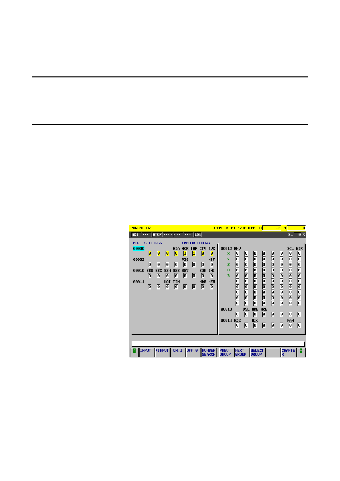
1.1 DISPLAYING PARAMETERS
The Parameter screen displays the values specified for CNC
parameters.
Parameter screen
Displaying the Parameter screen
Follow either of the procedures described below to display the
Parameter screen.
Method 1
Press the <SYSTEM> function key several times, until the
Parameter screen appears.
Method 2
(1) Press the <SYSTEM> function key.
(2) Click the [PARAMETER] soft key.
Fig. 1.1 (a) Parameter Screen
- 2 -
Page 13
B-63790EN/01 1.DISPLAYING PARAMETERS AND PITCH ERROR COMPENSATION DATA
Displaying specified parameters
The Parameter screen consists of multiple pages.
Follow one of the procedures described below to display the specified
parameter.
Method 1
Using the <PAGE ↑> <PAGE ↓> page keys, and the <↑> <↓>
<←> <→> cursor keys, move the cursor to display the desired
parameter.
Method 2
(1) Click the [NO. SEARCH] soft key.
(2) Key in the number of the parameter to be displayed.
(3) Click the [EXEC] soft key.
Method 3
(1) Key in the number of the parameter to be displayed.
(2) Click the [NO. SEARCH] soft key.
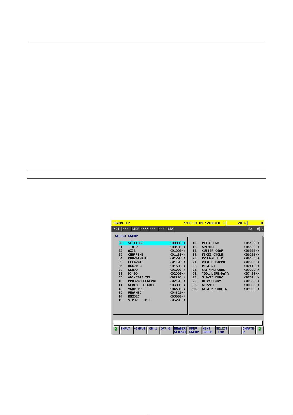
Select Group screen
The Select Group screen can be used to display a selected group of
parameters.
Displaying the Select Group screen
On the Parameter screen, select the [SELECTGROUP] soft key.
Fig. 1.1 (b) Select Group Screen
- 3 -
Page 14

1.DISPLAYING PARAMETERS AND PITCH ERROR COMPENSATION DATA B-63790EN/01
Selecting a group
Move the cursor to the group to be displayed.
Method 1
Use the <↑> <↓> <←> <→> cursor keys, move the cursor.
Method 2
(1) Click the [NO. SEARCH] soft key.
(2) Key in the number of the group to be displayed.
(3) Click the [EXEC] soft key.
Method 3
(1) Key in the number of the group to be displayed.
(2) Click the [NO. SEARCH] soft key.
Ending group selection
Click the [SELECTEND] soft key to exit from the Select Group
screen and return to the Parameter screen. The selected group of
parameters is displayed, starting with the first parameter.
- 4 -
Page 15
B-63790EN/01 1.DISPLAYING PARAMETERS AND PITCH ERROR COMPENSATION DATA
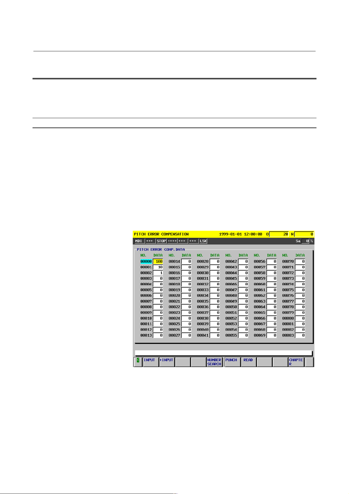
1.2 DISPLAYING PITCH ERROR COMPENSATION DATA
The Pitch Error Compensation screen displays the values specified for
pitch error compensation data.
Pitch Error Compensation screen
Displaying the Pitch Error Compensation screen
Follow either of the procedures described below to display the Pitch
Error Compensation screen.
Method 1
Press the <SYSTEM> function key several times, until the Pitch
Error Compensation screen appears.
Method 2
(1) Press the <SYSTEM> function key.
(2) Click the [PITCH ERROR] soft key.
Fig. 1.2 (a) Pitch Error Compensation Screen
- 5 -
Page 16

1.DISPLAYING PARAMETERS AND PITCH ERROR COMPENSATION DATA B-63790EN/01
Displaying specified pitch error compensation data
The Pitch Error Compensation screen consists of multiple pages.
Follow one of the procedures described below to display specified
pitch error compensation data.
Method 1
Using the <PAGE ↑> <PAGE ↓> page keys, and the <↑> <↓>
<←> <→> cursor keys, move the cursor to display the desired
pitch error compensation data.
Method 2
(1) Click the [NO. SEARCH] soft key.
(2) Key in the number of the pitch error compensation data to be
displayed.
(3) Click the [EXEC] soft key.
Method 3
(1) Key in the number of the pitch error compensation data to
be displayed.
(2) Click the [NO. SEARCH] soft key.
- 6 -
Page 17

B-63790EN/01 2.SETTING PARAMETERS AND PITCH ERROR COMPENSATION DATA
2 SETTING PARAMETERS AND PITCH
ERROR COMPENSATION DATA
This chapter explains how to set parameters and pitch error
compensation data from the MDI.
- 7 -
Page 18

2.SETTING PARAMETERS AND PITCH ERROR COMPENSATION DATA B-63790EN/01
2.1 SETTING PARAMETERS
The Parameter screen is used to set parameters from the MDI.
For an explanation of how to display the Parameter screen, see
Section 1.1, "Displaying Parameters."
Procedure for setting parameters
- Entering the mode
Enter MDI mode. Alternatively, press the emergency stop button to
enter the emergency stop status.
- Setting parameter PWE
On the Setting Parameter screen, set bit 0 of the setting/input-enabled
parameter PWE (No. 8000) to 1.
For the setting procedure, refer to Section II-9.3, "Displaying and
Setting Setting Parameters" in the "FANUC Series 15i/150i-MB
OPERATOR'S MANUAL (Operation) (B-63784EN-1)."
- Moving the cursor
Move the cursor to the parameter to be set.
Method 1
Using the <PAGE ↑> <PAGE ↓> page keys, and the <↑> <↓>
<←> <→> cursor keys, to move the cursor.
Method 2
(1) Click the [NO. SEARCH] soft key.
(2) Key in the parameter number.
(3) Click the [EXEC] soft key.
Method 3
(1) Key in the parameter number.
(2) Click the [NO. SEARCH] soft key.
- Entering a setting (absolute input)
Method 1
(1) Click the [INPUT] soft key.
(2) Key in the desired setting.
(3) Click the [EXEC] soft key.
Method 2
(1) Key in the desired setting.
(2) Click the [INPUT] soft key.
Method 3
(1) Key in the desired setting.
(2) Click the [INPUT] soft key.
- 8 -
Page 19

B-63790EN/01 2.SETTING PARAMETERS AND PITCH ERROR COMPENSATION DATA
- Entering a setting (incremental input)
Method 1
(1) Click the [+INPUT] soft key.
(2) Key in the value to be added to the current setting.
(3) Click the [EXEC] soft key.
Method 2
(1) Key in the value to be added to the current setting.
(2) Click the [+INPUT] soft key.
NOTE
For bit/bit axis/bit spindle type parameters,
incremental input is not possible. Even if the
[+INPUT] soft key is clicked, absolute input is
assumed.
- Bit ON:1
By clicking the [ON:1] soft key, the bit of a bit/bit axis/bit spindle
type parameter on which the cursor is displayed is set to 1.
If the cursor is displayed on all bits, all the bits are set to 1.
- Bit OFF:0
- Ending the setting
By clicking the [OFF:0] soft key, the bit of a bit/bit axis/bit spindle
type parameter on which the cursor is displayed is set to 0.
If the cursor is displayed on all bits, all the bits are set to 0.
When parameters have been set, set bit 0 of the setting/input-enabled
parameter PWE (No. 8000) to 0.
NOTE
The blank bits in the parameter list (Chapter 4,
"DESCRIPTION OF PARAMETERS") and the
parameters displayed on the Parameter screen but
not shown on the list are either reserved for future
expansion or used internally in the CNC. Do not
change the values of these parameter bits.
- 9 -
Page 20

2.SETTING PARAMETERS AND PITCH ERROR COMPENSATION DATA B-63790EN/01
2.2 SETTING PITCH ERROR COMPENSATION DATA
For an explanation of how to display the Pitch Error Compensation
screen, see Section 1.2, "Displaying Pitch Error Compensation Data."
The Pitch Error Compensation screen is used to set pitch error
compensation data.
Procedure for setting pitch error compensation data
- Entering the mode
Enter MDI mode. Alternatively, press the emergency stop button to
enter the emergency stop status.
- Setting parameter PWE
On the Setting Parameter screen, set bit 0 of the setting/input-enabled
parameter PWE (No. 8000) to 1.
For the setting procedure, refer to Section II-9.3, "Displaying and
Setting Setting Parameters" in the "FANUC Series 15i/150i-MA
OPERATOR'S MANUAL (Operation)."
- Moving the cursor
Move the cursor to the pitch error compensation data to be set.
Method 1
Using the <PAGE ↑> <PAGE ↓> page keys, and the <↑> <↓>
<←> <→> cursor keys, to move the cursor.
Method 2
(1) Click the [NO. SEARCH] soft key.
(2) Key in the pitch error compensation data number.
(3) Click the [EXEC] soft key.
Method 3
(1) Key in the pitch error compensation data number.
(2) Click the [NO. SEARCH] soft key.
- Entering a setting (absolute input)
Method 1
(1) Click the [INPUT] soft key.
(2) Key in the desired setting.
(3) Click the [EXEC] soft key.
Method 2
(1) Key in the desired setting.
(2) Click the [INPUT] soft key.
Method 3
(1) Key in the desired setting.
(2) Click the [INPUT] soft key.
- 10 -
Page 21

B-63790EN/01 2.SETTING PARAMETERS AND PITCH ERROR COMPENSATION DATA
- Entering a setting (incremental input)
Method 1
(1) Click the [+INPUT] soft key.
(2) Key in the value to be added to the current setting.
(3) Click the [EXEC] soft key.
Method 2
(1) Key in the value to be added to the current setting.
(2) Click the [+INPUT] soft key.
- 11 -
Page 22

3.INPUTTING AND OUTPUTTING PARAMETERS USING EXTERNAL INPUT/OUTPUT DEVICES B-63790EN/01
3 INPUTTING AND OUTPUTTING
PARAMETERS USING EXTERNAL
INPUT/OUTPUT DEVICES
This chapter explains the procedures for inputting and outputting
parameters using the input/output device connected to the
reader/punch interface or using a memory card, as well as
input/output formats.
- 12 -
Page 23

B-63790EN/01 3.INPUTTING AND OUTPUTTING PARAMETERS USING EXTERNAL INPUT/OUTPUT DEVICES
3.1 INPUTTING AND OUTPUTTING PARAMETERS ON THE
PARAMETER SCREEN
This section explains the procedures for inputting and outputting
parameters on the Parameter screen.
Before parameters can be input and output, the parameters related to
the input/output device must be set.
Displaying the Parameter screen
Follow either of the procedures described below to display the
Parameter screen.
Method 1
Press the <SYSTEM> function key several times, until the
Parameter screen appears.
Method 2
(1) Press the <SYSTEM> function key.
(2) Click the [PARAMETER] soft key.
Outputting parameters
Method 1 (neither the output file name nor number need be specified)
(1) Enter MDI mode.
(2) Click the [PUNCH] soft key.
(3) Click the [PARAMETER] soft key.
Method 2 (the output file name is specified)
(1) Enter MDI mode.
(2) Click the [PUNCH] soft key.
(3) Click the ["FILE NAME] soft key.
(4) Key in the file name.
(5) Click the [FILE NAME"] soft key.
(6) Click the [PARAMETER] soft key.
Method 3 (the file number is specified, one of three methods)
(1) Enter MDI mode.
(2) Click the [PUNCH] soft key.
(3) Click the [(FILE#)] soft key.
(4) Key in the file number.
(5) Click the [PARAMETER] soft key.
Method 4 (the file number is specified, one of three methods)
(1) Enter MDI mode.
(2) Click the [PUNCH] soft key.
(3) Click the <N> address key.
(4) Key in the file number.
(5) Click the [PARAMETER] soft key.
Method 5 (the file number is specified, one of three methods)
(1) Enter MDI mode.
(2) Click the <N> address key.
(3) Key in the file number.
(4) Click the [PUNCH] soft key.
- 13 -
Page 24

3.INPUTTING AND OUTPUTTING PARAMETERS USING EXTERNAL INPUT/OUTPUT DEVICES B-63790EN/01
Inputting parameters
Method 1 (neither the input file name nor number need be specified)
(1) Enter MDI mode.
(2) Enter the emergency stop status.
(3) Click the [READ] soft key.
(4) Click the [PARAMETER] soft key.
Method 2 (the input file is specified with its file name)
(1) Enter MDI mode.
(2) Enter the emergency stop status.
(3) Click the [READ] soft key.
(4) Click the ["FILE NAME] soft key.
(5) Key in the file name.
(6) Click the [FILE NAME"] soft key.
(7) Click the [PARAMETER] soft key.
Method 3 (the input file is specified with its file number, one of three
methods)
(1) Enter MDI mode.
(2) Enter the emergency stop status.
(3) Click the [READ] soft key.
(4) Click the [(FILE#)] soft key.
(5) Key in the file number.
(6) Click the [PARAMETER] soft key.
Method 4 (the input file is specified with its file number, one of three
methods)
(1) Enter MDI mode.
(2) Enter the emergency stop status.
(3) Click the [READ] soft key.
(4) Click the <N> address key.
(5) Key in the file number.
(6) Click the [PARAMETER] soft key.
Method 5 (the input file is specified with its file number, one of three
methods)
(1) Enter MDI mode.
(2) Enter the emergency stop status.
(3) Click the <N> address key.
(4) Key in the file number.
(5) Click the [READ] soft key.
- 14 -
Page 25

B-63790EN/01 3.INPUTTING AND OUTPUTTING PARAMETERS USING EXTERNAL INPUT/OUTPUT DEVICES
NOTE
1 When outputting and inputting parameters to and
from a FANUC Floppy Cassette, FANUC FA Card,
and FANUC Handy File, you can specify the
input/output file with its file name or number.
2 When outputting and inputting parameters to and
from a memory card, you can specify the
input/output file with its file name.
3 When method 1 (in which neither the output file
name nor number need be specified), described in
"Outputting parameters," is used to output
parameters to a FANUC Floppy Cassette, FANUC
FA Card, FANUC Handy File, and memory card,
the file name will be CNC-PARA.TXT.
- 15 -
Page 26

3.INPUTTING AND OUTPUTTING PARAMETERS USING EXTERNAL INPUT/OUTPUT DEVICES B-63790EN/01
3.2 INPUTTING AND OUTPUTTING PARAMETERS ON THE
FLOPPY DIRECTORY SCREEN
This section explains the procedures for inputting and outputting
parameters on the Floppy Directory screen, using the FANUC Floppy
Cassette, FANUC FA Card, FANUC Handy File, or FANUC
PROGRAM FILE Mate connected to the serial interface (RS-232-C
or RS-422).
Before parameters can be input and output, the parameters related to
the input/output device must be set.
Displaying the Floppy Directory screen
Follow either of the procedures described below to display the Floppy
Directory screen.
Method 1
Press the <OFFSET/SETTING> function key several times, until
the Floppy Directory screen appears.
Method 2
(1) Press the <OFFSET/SETTING> function key.
(2) Click the [RS232C] soft key.
Outputting parameters
(1) Click the [DATA SELECT] soft key.
(2) Click the [PARAMETER] soft key.
"PARAMETER" appears in IN/OUT DATA.
(3) Follow either of the procedures described below to set the output
file name
Method 1 (the file name is entered using MDI keys)
(1) Click the [NAME INPUT] soft key.
(2) Click the ["FILE NAME] soft key.
(3) Enter the file name with MDI keys.
(4) Click the [FILE NAME"] soft key.
(5) Click the [EXEC] soft key.
Method 2 (the file name is selected from a file list)
(1) Click the [DIR. VIEW] soft key.
A list of files contained in the input/output device is
displayed. If the list cannot be displayed on a single page,
"Prev Page" and "Next Page" are displayed in PAGE
SELECT to indicate that there are multiple pages.
Press the <PAGE ↑> <PAGE ↓> key to display the
specified page.
(2) Move the cursor to the desired output file name.
(3) Click the [NAME GET] soft key.
(4) Enter MDI mode.
(5) Click the [DATA PUNCH] soft key.
(6) Click the [EXEC] soft key.
- 16 -
Page 27

B-63790EN/01 3.INPUTTING AND OUTPUTTING PARAMETERS USING EXTERNAL INPUT/OUTPUT DEVICES
Inputting parameters
(1) Click the [DATA SELECT] soft key.
(2) Click the [PARAMETER] soft key.
"PARAMETER" appears in IN/OUT DATA.
(3) Click the [DIR. VIEW] soft key.
A list of files contained in the input/output device is displayed. If
the list cannot be displayed on a single page, "Prev Page" and
"Next Page" are displayed in PAGE SELECT to indicate that
there are multiple pages.
Press the <PAGE ↑> <PAGE ↓> key to display the specified
page.
(4) Move the cursor to the desired input file name.
(5) Enter MDI mode.
(6) Enter the emergency stop status.
(7) Click the [DATA READ] soft key.
(8) Click the [EXEC] soft key.
- 17 -
Page 28

3.INPUTTING AND OUTPUTTING PARAMETERS USING EXTERNAL INPUT/OUTPUT DEVICES B-63790EN/01
3.3 INPUTTING AND OUTPUTTING PARAMETERS ON THE
MEMORY CARD SCREEN
This section explains the procedures for inputting and outputting
parameters on the Memory Card screen.
Before parameters can be input and output, the parameters related to
the input/output device must be set.
Displaying the Memory Card screen
Follow either of the procedures described below to display the
Memory Card screen.
Method 1
Press the <OFFSET/SETTING> function key several times, until
the Memory Card screen appears.
Method 2
(1) Press the <OFFSET/SETTING> function key.
(2) Click the [MEMCARD] soft key.
Outputting parameters
(1) Click the [DATA SELECT] soft key.
(2) Click the [PARAMETER] soft key.
"PARAMETER" appears in IN/OUT DATA.
(3) Follow either of the procedures described below to set the output
file name.
Method 1 (the file name is entered using MDI keys)
(1) Click the [NAME INPUT] soft key.
(2) Click the ["FILE NAME] soft key.
(3) Enter the file name with MDI keys.
(4) Click the [FILE NAME"] soft key.
(5) Click the [EXEC] soft key.
Method 2 (the file name is selected from a file list)
(1) Click the [DIR. VIEW] soft key.
A list of files contained in the input/output device is
displayed. If the list cannot be displayed on a single
page, "Prev Page" and "Next Page" are displayed in
PAGE SELECT to indicate that there are multiple
pages.
Press the <PAGE ↑> <PAGE ↓> key to display the
specified page.
(2) Move the cursor to the desired output file name.
(3) Click the [NAME GET] soft key.
(4) Enter MDI mode.
(5) Click the [DATA PUNCH] soft key.
(6) Click the [EXEC] soft key.
- 18 -
Page 29

B-63790EN/01 3.INPUTTING AND OUTPUTTING PARAMETERS USING EXTERNAL INPUT/OUTPUT DEVICES
Inputting parameters
(1) Click the [DATA SELECT] soft key.
(2) Click the [PARAMETER] soft key.
"PARAMETER" appears in IN/OUT DATA.
(3) Click the [DIR. VIEW] soft key.
A list of files contained in the input/output device is displayed. If
the list cannot be displayed on a single page, "Prev Page" and
"Next Page" are displayed in PAGE SELECT to indicate that
there are multiple pages.
Press the <PAGE ↑> <PAGE ↓> key to display the specified
page.
(4) Move the cursor to the desired input file name.
(5) Enter MDI mode.
(6) Enter the emergency stop status.
(7) Click the [DATA READ] soft key.
(8) Click the [EXEC] soft key.
- 19 -
Page 30
3.INPUTTING AND OUTPUTTING PARAMETERS USING EXTERNAL INPUT/OUTPUT DEVICES B-63790EN/01
3.4 INPUT/OUTPUT FORMATS
This section explains the input/output formats for parameters and
pitch error compensation data.
3.4.1 Input/Output Formats for Parameters
Parameters are classified according to data types, as follows.
- Bit type
- Bit axis type
- Bit spindle type
- Integer type
- Integer axis type
- Integer spindle type
- Real type
- Real axis type
- Real spindle type
- Keywords
Bit/bit axis/bit spindle type parameters are represented by 8-digit
binary numbers, with each digit occupying a single bit.
The valid value ranges of the individual integer/integer axis/integer
spindle/real/real axis/real spindle type parameters differ. For details,
see the description of each parameter.
The following alphabetic characters are used as keywords.
The numeric values following the keywords have the meanings
described below.
Keyword Description of the numeric value following the keyword
N
A
S
P
M
I
Parameter number
Controlled axis number of an axis type parameter (1 or
above)
Spindle number of a spindle type parameter (1 or above)
Value of a parameter that does not depend on
inch/metric switching
Metric-input-time value of a parameter dependent on
inch/metric switching
Inch-input-time value of a parameter dependent on
inch/metric switching
- 20 -
Page 31

B-63790EN/01 3.INPUTTING AND OUTPUTTING PARAMETERS USING EXTERNAL INPUT/OUTPUT DEVICES
- Inch/metric switching
The data specified for parameters dependent on inch/metric switching,
such as length and feedrate parameters, is determined to be in either
inch or metric mode depending on the mode assumed at input time for
input from the MDI and depending on whether the keyword preceding
the data is I or M for input from an external input/output device.
These I and M keywords are added to data as appropriate when that
data is output from an external input/output device.
If the mode assumed at input time or the keyword does not match the
mode assumed when the data is to be used, for example, the data input
in inch mode is to be used in metric mode, the CNC automatically
converts the data before use, eliminating the need to change the data
according to the mode change. In addition, in the display of parameter
data, data is converted according to the mode assumed at display time,
before the data is displayed. When the data is to be output from the
external input/output device, it is converted back to the original data
according to the keyword or mode.
- Bit type format
N ***** P ******** ;
- Bit axis type format
The 8-digit binary number following P represents the values (0 or 1)
of the bits of the parameter, with the first digit corresponding to bit 0
and the eighth digit to bit 7. Leading zeros cannot be omitted.
; is an end of block character (LF for ISO code and CR for EIA code).
Example
N00010P00000001;
Parameter number 10
Parameter value Bit 0 is 1 and the others are 0.
N ***** A ** P ******** A ** P ******** . . . . ;
The numeric value following N represents the parameter number.
The numeric value following A represents the controlled axis number
(1 or above).
The 8-digit binary number following P represents the values (0 or 1)
of the bits of the parameter for that controlled axis, with the first digit
corresponding to bit 0 and the eighth digit to bit 7. Leading zeros
cannot be omitted.
; is an end of block character (LF for ISO code and CR for EIA code).
Example
N0005A1P10000001A2P10000001A3P10000001A4P00001001....;
Parameter number 1005
Parameter values
First axis: Bits 0 and 7 are 1 and the others are 0.
Second axis: Bits 0 and 7 are 1 and the others are 0.
Third axis: Bits 0 and 7 are 1 and the others are 0.
Fourth axis: Bits 0 and 3 are 1 and the others are 0.
- 21 -
Page 32

3.INPUTTING AND OUTPUTTING PARAMETERS USING EXTERNAL INPUT/OUTPUT DEVICES B-63790EN/01
- Bit spindle type format
N ***** S * P ******** S * P ******** . . . . ;
The numeric value following N represents the parameter number.
The numeric value following S represents the spindle number (1 or
above).
The 8-digit binary number following P represents the values (0 or 1)
of the bits of the parameter for that spindle, with the first digit
corresponding to bit 0 and the eighth digit to bit 7. Leading zeros
cannot be omitted.
; is an end of block character (LF for ISO code and CR for EIA code).
Example
N05603S1P00001000S2P00001000S3P00000000S4P000000000;
Parameter number 5603
Parameter values
First spindle: Bit 3 is 1 and the others are 0.
Second spindle: Bit 3 is 1 and the others are 0.
Third spindle: All bits are 0.
Fourth spindle: All bits are 0.
- Integer type format
N ***** P ****** ;
The numeric value following N represents the parameter number.
The numeric value following P represents the value (integer) of the
parameter.
; is an end of block character (LF for ISO code and CR for EIA code).
Example
N00100P31515;
Parameter number 100
Parameter value 31515
- 22 -
Page 33

B-63790EN/01 3.INPUTTING AND OUTPUTTING PARAMETERS USING EXTERNAL INPUT/OUTPUT DEVICES
- Integer axis type format
N ***** A ** P ****** A ** P ****** . . . . ;
The numeric value following N represents the parameter number.
The numeric value following A represents the controlled axis number
(1 or above).
The numeric value following P represents the value (integer) of the
parameter.
; is an end of block character (LF for ISO code and CR for EIA code).
Example
N01020A1P88A2P89A3P90A4P66......;
Parameter number 1020
Parameter values
First axis: 88
Second axis: 89
Third axis: 90
Fourth axis: 66
- Integer spindle type format
N ***** S * P ****** S * P ****** . . . . ;
The numeric value following N represents the parameter number.
The numeric value following S represents the controlled axis number
(1 or above).
The numeric value following P represents the value (integer) of the
parameter.
; is an end of block character (LF for ISO code and CR for EIA code).
Example
N05680S1P19S2P19S3P0S4P0;
Parameter number 5680
Parameter values
First spindle: 19
Second spindle: 19
Third spindle: 0
Fourth spindle: 0
- 23 -
Page 34

3.INPUTTING AND OUTPUTTING PARAMETERS USING EXTERNAL INPUT/OUTPUT DEVICES B-63790EN/01
- Real type format
N ***** P ****** ;
N ***** M ****** ;
N ***** I ****** ;
The numeric value following N represents the parameter number.
The numeric value following P, M, or I represents the value (real) of
the parameter.
; is an end of block character (LF for ISO code and CR for EIA code).
Example
N01451P5000.0;
Parameter number 1451
Parameter number 000.0
- Real axis type format
N ***** A ** P ****** A ** P ****** . . . . ;
N ***** A ** M ****** A ** M ****** . . . . ;
N ***** A ** I ****** A ** I ****** . . . . ;
The numeric value following N represents the parameter number.
The numeric value following A represents the controlled axis number
(1 or above).
The numeric value following P, M, or I represents the value (real) of
the parameter.
; is an end of block character (LF for ISO code and CR for EIA code).
Example
N01220A1M50.0A2M60.0A3M70.0A4M0.0A5M0.0 ........;
Parameter number 1220
Parameter values
First axis: 50.0
Second axis: 60.0
Third axis: 70.0
Fourth axis: 0.0
Fifth axis: 0.0
- 24 -
Page 35

B-63790EN/01 3.INPUTTING AND OUTPUTTING PARAMETERS USING EXTERNAL INPUT/OUTPUT DEVICES
- Real spindle type format
N ***** S * P ****** S * P ****** . . . . ;
N ***** S * M ****** S * M ****** . . . . ;
N ***** S * I ****** S * I ****** . . . . ;
The numeric value following N represents the parameter number.
The numeric value following S represents the controlled axis number
(1 or above).
The numeric value following P, M, or I represents the value (real) of
the parameter.
; is an end of block character (LF for ISO code and CR for EIA code).
Example
N05898S1P30.0S2P30.0S3P0.0S4P0.0;
Parameter number 5898
Parameter values
First spindle: 30.0
Second spindle: 30.0
Third spindle: 0.0
Fourth spindle: 0.0
- Beginning and end of a record
A record of parameters begins with "%" and ends with "%."
When parameters and pitch error compensation data are collected into
a single file, the file begins and ends with "%."
Example
%; ................................ Beginning of a record
N00000P00001100;
N00002P00000000;
:
N09162P00000000;
N09163P00000000;
% ................................ End of the record
- 25 -
Page 36

3.INPUTTING AND OUTPUTTING PARAMETERS USING EXTERNAL INPUT/OUTPUT DEVICES B-63790EN/01
3.4.2 Input/Output Format for Pitch Error Compensation Data
- Keywords
The following alphabetic characters are used as keywords.
The numeric values following the keywords have the meanings
described below.
Keyword Description of the numeric value following the keyword
N
P
- Format
Pitch error compensation data is output in the following format.
N ***** P **** ;
The 5-digit numeric value following N represents the pitch error
compensation data number. Note that this number is equal to the
actual pitch error compensation data number plus 10000.
The numeric value following P represents the value (integer) of the
pitch error compensation data, which is in the range of -128 to 127.
; is an end of block character (LF for ISO code and CR for EIA code).
Pitch error compensation data number
Pitch error compensation data value
- Beginning and end of a record
A record of pitch error compensation data begins with "%" and ends
with "%."
When parameters and pitch error compensation data are collected into
a single file, the file begins and ends with "%."
Example
N10001P100;
Pitch error compensation data number
Pitch error compensation data value
Example
% ; .................................... Beginning of a record
N10000P10;
N10001P100;
:
N11279P0;
% .................................... End of the record
- 26 -
Page 37

B-63790EN/01 4.DESCRIPTION OF PARAMETERS
4 DESCRIPTION OF PARAMETERS
4.1 DATA TYPES
Parameters are classified according to data types, as follows:
Data type Valid data range Remarks
Bit type
Bit axis type
Bit spindle type
Integer type
Integer axis type
Integer spindle type
Real type
Real axis type
Real spindle type
0 or 1
0 to ±999999999
See the Standard
Parameter Setting
Tables.
Some parameters are handled as
unsigned data.
NOTE
1 Each of bit, bit axis, and bit spindle type parameters
contains eight bits (eight different meanings) for a
single data number.
2 The axis type means that independent data can be
set for each controlled axis.
3 The spindle type means that independent data can
be set for each spindle.
4 The valid data ranges are general ones. The valid
data range differs from one parameter to another.
For details, see the explanation of each parameter.
- 27 -
Page 38

4.DESCRIPTION OF PARAMETERS B-63790EN/01
4.2 REPRESENTATION OF PARAMETERS
Bit, bit axis, and bit spindle types
#7 #6 #5 #4 #3 #2 #1 #0
0000 EIA NCR ISP CTV TVC
Data
number
Data (#0 to #7 indicate bit positions.)
Types other than bit, bit axis, and bit spindle types
1023 Servo axis number of each axis
Data
number
NOTE
The blank bits in the parameter list (Chapter 4,
"DESCRIPTION OF PARAMETERS") and the
parameters displayed on the Parameter screen but
not shown on the list are reserved for future
expansion. Be sure to set these parameter bits to 0.
Data
- 28 -
Page 39

B-63790EN/01 4.DESCRIPTION OF PARAMETERS
4.3 STANDARD PARAMETER SETTING TABLES
Overview
This section specifies the standard minimum data units and standard
valid data ranges of real, real axis, and real spindle type CNC
parameters. The data type of each parameter and its unit of data
conform to the specifications of each function.
Explanations
(A) Length and angle parameters (type 1)
Unit of data
mm
deg.
inch
Increment
system
IS-A 0.01 -999999.99 to +999999.99
IS-B 0.001 -999999.999 to +999999.999
IS-C 0.0001 -99999.9999 to +99999.9999
IS-D 0.00001 -9999.99999 to +9999.99999
IS-E 0.000001 -999.999999 to +999.999999
IS-A 0.001 -99999.999 to +99999.999
IS-B 0.0001 -99999.9999 to +99999.9999
IS-C 0.00001 -9999.99999 to +9999.99999
IS-D 0.000001 -999.999999 to +999.999999
IS-E 0.0000001 -99.9999999 to +99.9999999
Minimum data unit Valid data range
(B) Length and angle parameters (type 2)
Unit of data
mm
deg.
inch
Increment
system
IS-A 0.01 0.00 to +999999.99
IS-B 0.001 0.000 to +999999.999
IS-C 0.0001 0.0000 to +99999.9999
IS-D 0.00001 0.00000 to +9999.99999
IS-E 0.000001 0.000000 to +999.999999
IS-A 0.001 0.000 to +99999.999
IS-B 0.0001 0.0000 to +99999.9999
IS-C 0.00001 0.00000 to +9999.99999
IS-D 0.000001 0.000000 to +999.999999
IS-E 0.0000001 0.0000000 to +99.9999999
Minimum data unit Valid data range
- 29 -
Page 40

4.DESCRIPTION OF PARAMETERS B-63790EN/01
(C) Velocity and angular velocity parameters
Unit of data
mm/min
deg./min
inch/min
Increment
system
IS-A 0.01 0.0 to +2400000.0
IS-B 0.001 0.0 to +240000.0
IS-C 0.0001 0.0 to +99999.9999
IS-D 0.00001 0.0 to +9999.99999
IS-E 0.000001 0.0 to +999.999999
IS-A 0.001 0.0 to +96000.000
IS-B 0.0001 0.0 to +9600.0000
IS-C 0.00001 0.0 to +4000.00000
IS-D 0.000001 0.0 to +400.000000
IS-E 0.0000001 0.0 to +40.0000000
Minimum data unit Valid data range
(D) Acceleration and angular acceleration parameters
Unit of data
mm/sec
deg./sec
inch/sec
2
2
2
Increment
system
IS-A 0.01 0.00 to +999999.99
IS-B 0.001 0.000 to +999999.999
IS-C 0.0001 0.0000 to +99999.9999
IS-D 0.00001 0.00000 to +9999.99999
IS-E 0.000001 0.000000 to +999.999999
IS-A 0.001 0.000 to +999999.999
IS-B 0.0001 0.0000 to +99999.9999
IS-C 0.00001 0.00000 to +9999.99999
IS-D 0.000001 0.000000 to +999.999999
IS-E 0.0000001 0.0000000 to +99.9999999
Minimum data unit Valid data range
Notes
(1) Values are rounded up or down to the nearest multiples of the
minimum data unit.
(2) A valid data range means the range of CNC performance.
Therefore, set data within this range. This range may differ from
the performance of an actual machine.
(3) For information on the ranges of commands to the CNC, refer to
Appendix, "List of Command Ranges," in the "FANUC Series
15i/150i-MB OPERATOR'S MANUAL (Programming)" (B-
63784EN).
- 30 -
Page 41

B-63790EN/01 4.DESCRIPTION OF PARAMETERS
ANCR
4.4 SETTING PARAMETERS (DATA NO. 0000 AND LATER)
#7 #6 #5 #4 #3 #2 #1 #0
0000 RDN EI
[Input type] Setting input
[Data type] Bit
#0 TVC Specifies whether TV check is performed.
0: Do not perform.
1: Perform.
#1 CTV Specifies whether characters are counted for TV check during control
out.
0: Count.
1: Do not count.
#2 ISP Specifies whether ISO codes contain a parity bit.
0: Contain parity bit.
1: Do not contain parity bit.
A parity bit is located at channel 8 in a punched tape in the ISO code.
#3 NCR Specifies how to punch an EOB (end-of-block) code when using ISO
codes.
0: Punch LF CR CR.
1: Punch LF.
NOTE
This bit is disabled, when bit 2 (CRF) of parameter
No.0002 is set to 1.
ISP CTV TVC
#4 EIA Specifies the code system to use for punch codes.
0: ISO code
1: EIA code
#6 RDN Specifies whether the Remote Diagnostic Function is used
0: Disable
1: Enable
The device setting for Remote Diagnostic Function is used current
setting when this bit is set to 1. After all device parameters are set,
this bit should be set to 1. When the device parameters are changed,
this bit must be set to 0.
NOTE
During this bit is set to 1, the communication device is
occupied by Remote Diagnostic Function. So, while
this bit is 1, don't read data and don't punch data from
CNC side.
- 31 -
Page 42

4.DESCRIPTION OF PARAMETERS B-63790EN/01
#7 #6 #5 #4 #3 #2 #1 #0
0002 SJZ PZS CRF
[Input type] Setting input
[Data type] Bit
#2 CRF Specifies how to punch an EOB (end-of-block) code when using ISO
codes.
0: Use parameter NCR (No.0#3).
1: Punch CR LF.
#3 PZS
0: Do not suppress the zeros of O numbers during the punching of a
part program.
1: Suppress the zeros of O numbers during the punching of a part
program.
#7 SJZ Manual reference position return:
0: Performs reference position return using deceleration dogs if the
reference position has not been established and performs
positioning to the reference position with rapid traverse
irrespective of deceleration dogs if the reference position has
already been established.
1: Always performs reference position return using deceleration
dogs.
SJZ is effective to those axes for which HJZ, bit 4 of parameter No.
1013, is 1. After the reference position has been established using
the function for setting the reference position without dogs (DOG, bit
7 of parameter No. 1007 = 1), however, manual reference position
return always performs positioning to the reference position with
rapid traverse irrespective of the setting of SJZ.
#7 #6 #5 #4 #3 #2 #1 #0
0009 SPI SVI IDW
[Input type] Setting input
[Data type] Bit
# 0 IDW Specifies whether to permit editing of the servo or spindle
information screen.
0: Do not permit editing.
1: Permit editing.
# 1 SVI Specifies whether to display the servo information screen.
0: Display the servo information screen.
1: Do not display the servo information screen.
NOTE
After this parameter has been set, the power must be
off turned off then back on for the setting to become
effective.
# 2 SPI Specifies whether to display the spindle information screen.
0: Display the servo information screen.
1: Do not display the servo information screen.
- 32 -
Page 43

B-63790EN/01 4.DESCRIPTION OF PARAMETERS
#7 #6 #5 #4 #3 #2 #1 #0
0010 SBO SBC SBM SB8 SB7 SQN INI
[Input type] Setting input
[Data type] Bit
#0 INI Specifies whether the increment system is metric or in inches.
0: Metric input
1: Inch input
#1 SQN Specifies whether sequence numbers are automatically inserted.
0: Do not insert.
1: Insert.
#3 SB7 Specifies whether to stop after each block of custom macro statements
in programs O7000 to O7999.
0: Do not stop after each block.
1: Stop after each block.
This bit is used to check programs O7000 to O7999 containing
custom macro statements.
#4 SB8 Specifies whether to stop after each block of custom macro statements
in programs O8000 to O8999.
0: Do not stop after each block.
1: Stop after each block.
This bit is used to check programs O8000 to O8999 containing
custom macro statements.
#5 SBM Specifies whether to stop after each block of custom macro statements
in any program.
0: Do not stop after each block. However, when stopping is
specified in SB7 or SB8, stopping will occur in programs
affected by these parameters.
1: Stop after each block.
This bit is used to check programs containing custom macro
statements.
#6 SBC Specifies whether to stop after each block in hole-machining canned
cycles.
0: Do not stop after each block.
1: Stop after each block.
This bit is used to check programs containing canned cycles.
#7 SBO Specifies whether to stop after each block automatically generated in
the NC for cutter or tool tip radius compensation.
0: Do not stop after each block.
1: Stop after each block.
This bit is used to check programs containing cutter or tool tip radius
compensation.
- 33 -
Page 44

4.DESCRIPTION OF PARAMETERS B-63790EN/01
R
#7 #6 #5 #4 #3 #2 #1 #0
0011 NOT TIM ND8 NE8
[Input type] Setting input
[Data type] Bit
#0 NE8 Specifies whether to permit editing of O8000 to O8999 programs.
0: Permit editing.
1: Do not permit editing.
#1 ND8 Specifies whether to display the program being executed on the
screen for programs O8000 to O8999.
0: Display program being executed.
1: Do not display program being executed.
When there is no need to display custom macros or other programs
being executed, set this parameter to 1.
#4 TIM Specifies the information displayed on the screen for the program No.
and name directory.
0: Display program No., name, and memory used.
1: Display program No., name, and processing time.
#5 NOT Specifies whether to use Tool Nos. to specify output of tool pot Nos.
and tool offsets.
0: Use tool Nos. (H/D codes cannot be used to specify tool length
compensation and cutter compensation.)
1: Do not use tool Nos. (H/D codes can be used to specify tool
length compensation and cutter compensation.)
#7 #6 #5 #4 #3 #2 #1 #0
0012 RMV SCL MI
[Input type] Setting input
[Data type] Bit axis
#0 MIR For each axis, specifies whether to use its mirror image.
0: Do not use mirror image (normal).
1: Use mirror image (mirror).
#1 SCL For this axis, specifies whether scaling is used.
0: Do not use scaling.
1: Use scaling.
#7 RMV For each axis, specifies whether to detach the shaft corresponding to
the control axis.
0: Do not detach.
1: Detach.
(Equivalent to the control axis detach signals DTCH1, DTCH2, and
so on.)
Effective when RMB (bit 7 of parameter No. 1005) is set to 1.
- 34 -
Page 45

B-63790EN/01 4.DESCRIPTION OF PARAMETERS
A
#7 #6 #5 #4 #3 #2 #1 #0
0013 DSL HDE HKE
[Input type] Setting input
[Data type] Bit
#4 HKE Specifies whether to store the history of key operations.
0: Do not store the history.
1: Store the history.
#5 HDE Specifies whether to store the history of DI/DO.
0: Do not store the history.
1: Store the history.
#6 DSL Specifies whether to display the system log screen.
0: Do not display the screen.
1: Display the screen.
#7 #6 #5 #4 #3 #2 #1 #0
0014 HD2 NIC
SG FAN
[Input type] Setting input
[Data type] Bit
#1 FAN Specifies whether to ignore alarm FAN MOTOR STOP (OH002).
0: Do not ignore the alarm.
1: Ignore the alarm.
#4 ASG Specifies what compensation is to be changed in the Changing Active
Offset Value with Manual Move mode for offset memory B/C, as
follows:
0: Wear compensation
1: Geometry compensation
This parameter is valid for offset memory B/C.
#5 NIC Specifies whether to perform an interference check when
compensation plane switching occurs during three-dimensional cutter
compensation.
0: Perform.
1: Do not perform.
#7 HD2 Specifies whether the size of one file can exceed 2000 m when using
a floppy cassette, the PROGRAM FILE Mate, HANDY FILE, or FA
card.
0: Within 2000 m
1: Can exceed 2000 m
- 35 -
Page 46

4.DESCRIPTION OF PARAMETERS B-63790EN/01
#7 #6 #5 #4 #3 #2 #1 #0
0015 NDM EKE OHS HPC SPS SVS
[Input type] Setting input
[Data type] Bit
#0 SVS Specifies whether to display the servo screen.
0: Display the servo screen.
1: Do not display the servo screen.
Specifies whether to display or hide the servo setting screen, servo
adjustment/monitor screen, servo function setting screen, servo alarm
screen, and backlash screen.
#1 SPS Specifies whether to display the spindle screen.
0: Display the spindle screen.
1: Do not display the spindle screen.
#2 HPC Specifies whether to enable the high-speed and high-precision
machining setting screen.
0: Enable the screen.
1: Disable the screen.
#3 OHS Specifies whether to display the operation history screen and the
signal selection screen.
0: Do not display the screens. (The alarm history screen can be
displayed.)
1: Display the screens.
#4 EKE Specifies whether to enable the [ALL CLEAR] soft key that erases
history data.
0: Disable the soft key.
1: Enable the soft key.
#7 NDM
The PROFIBUS-DP screen is
0: Displayed.
1: Not displayed.
The change of this bit takes effect at the next startup.
0016 Screen saver start time
[Input type] Setting input
[Data type] Integer
[Unit of data] min
[Valid data range] 0 - 127
When the operator does not operate the keyboard for the period
specified in this parameter, the saver screen is displayed. When 0 is
specified, the screen save function is disabled.
0020 Interface No. of input device for foreground
[Input type] Setting input
[Data type] Integer
[Valid data range] 0 - 21
This parameter specifies an interface number for a foreground input
device.
- 36 -
Page 47

B-63790EN/01 4.DESCRIPTION OF PARAMETERS
The device numbers for each device are listed below:
Device
number
1 RS-232-C channel 1 (JD5A on the main CPU board)
2 RS-232-C channel 2 (JD5B on the main CPU board)
3 RS-232-C channel 3 (JD36A on the display unit)
8 Memory card
9 PMC C board
10 Remote buffer
12 Remote Diagnose
13 RS-422 channel 1 (JD6A on the display unit)
14 Data server
15 Open CNC DNC operation interface
16 Open CNC Upload/Download interface
18 C language executor DNC operation interface
19 C language executor Upload/Download interface
20 RS-232-C channel 4 (JD5C on the additional-axis board)
21 RS-422 channel 2 (JD6B on the additional-axis board)
0021 Interface No. of output device for foreground
Device name
[Input type] Setting input
[Data type] Integer
[Valid data range] 0 - 21
This parameter specifies an interface number for a foreground output
device.
See the descriptions about parameter No. 0020 for the device
numbers.
If the screen hard copy function is enabled (parameter HDC (bit 7 of
parameter No. 2240) = 1), set this parameter to 8 (memory card).
0022 Interface No. of input device for background
[Input type] Setting input
[Data type] Integer
[Valid data range] 0 - 21
This parameter specifies an interface number for a background input
device.
See the descriptions about parameter No. 0020 for the device
numbers.
0023 Interface No. of output device for background
[Input type] Setting input
[Data type] Integer
[Valid data range] 0 - 21
This parameter specifies an interface number for a background output
device.
See the descriptions about parameter No. 0020 for the device
numbers.
- 37 -
Page 48

4.DESCRIPTION OF PARAMETERS B-63790EN/01
0024 Assignment of the communication with the PMC Ladder development tool
(FAPT LADDER-II, Ladder editing package)
[Input type] Setting input
[Data type] Integer
[Valid data range] 0 - 255
Assigns the communication with the PMC Ladder development tool
(FAPT LADDER-II, Ladder editing package).
The value of this parameter determines the communication to be
started, as follows:
0: At power-on, communication conforms to the settings on the
PMC setting screen (displayed by selecting [PMC], [SETING],
and the [ONLINE] screen in this order).*1
Communication stops if this parameter is changed from another
value to 0.
1: RS-232-C serial port 1 (JD5A)
2: RS-232-C serial port 2 (JD5B)
3: RS-232-C serial port 3 (JD36A)
4: RS-422 serial port (JD6A)
255: Do not allow communication with the PMC Ladder development
tool.
*1 When using HSSB, set the parameter to 0.
After system startup, communication settings can be changed with
this parameter or on the PMC setting screen.
Refer to the PMC Ladder Language Programming Manual (B61863E).
To use the online monitor function of the PMC Ladder development
tool, set the desired communication port number in this parameter.
To transfer sequence programs in offline mode, set this parameter to
"0." In addition, on the PMC [ONLINE] screen, select "NOT USE" in
the "RS-232C" field.
To forcibly stop the communication with the PMC Ladder
development tool, set this parameter to "255."
0031 Initial value used for automatic setting of sequence Nos.
[Input type] Setting input
[Data type] Integer
[Valid data range] 0 - 99999999
0032 Increment used for automatic setting of sequence No.
[Input type] Setting input
[Data type] Integer
[Valid data range] 0 - 99999999
If the increment is set to 0, no sequence Nos. are inserted.
- 38 -
Page 49

B-63790EN/01 4.DESCRIPTION OF PARAMETERS
0040 Serial port channel for Remote Diagnostic Function
[Input type] Setting input
[Data type] Integer
[Valid data range] 1 - 3
Selection of serial port channel for Remote Diagnostic Function.
1: RS-232-C Serial port1 (JD5A)
2: RS-232-C Serial port2 (JD5B)
3: RS-232-C Serial port3 (JD36A)
17: Modem card (PCMCIA card slot on the LCD unit)
0042 Password 1 for Remote Diagnostic Function
[Input type] Locked parameter
[Data type] Integer
[Valid data range] 0 - 99999999
0043 Keyword 1 for Remote Diagnostic Function
[Input type] Locked parameter
[Data type] Integer
[Valid data range] 0 - 99999999
0044 Password 2 for Remote Diagnostic Function
[Input type] Locked parameter
[Data type] Integer
[Valid data range] 0 - 99999999
0045 Keyword 2 for Remote Diagnostic Function
[Input type] Locked parameter
[Data type] Integer
[Valid data range] 0 - 99999999
0046 Password 3 for Remote Diagnostic Function
[Input type] Locked parameter
[Data type] Integer
[Valid data range] 0 - 99999999
0047 Keyword 3 for Remote Diagnostic Function
[Input type] Locked parameter
[Data type] Integer
[Valid data range] 0 - 99999999
Parameters (No.0042, 0044, 0046) set passwords for using the remote
diagnosis function.
With the remote diagnostic function, three types of passwords are
available for protecting data. These passwords help to prevent
- 39 -
Page 50

4.DESCRIPTION OF PARAMETERS B-63790EN/01
unauthorized persons from accessing system parameters and
machining programs.
Password 1:
Sets a password for all services of the remote diagnosis function.
(No remote diagnosis function services are available until this
password is entered on the host computer (personal or other)).
Password 2:
Sets a password for part programs. (Program-related operations
such as program data input/output and check cannot be
performed until this password is entered on the host computer
(personal or other)).
Password 3:
Sets a password for parameters. (Parameter-related operations
such as parameter data input/output and cannot be performed
until this password is entered on the host computer (personal or
other)).
Parameters (No.0043, 0045, 0047) set the keywords for passwords
used with the remote diagnostic function.
Keyword 1:
Keyword for password 1(parameter No.0042)
Keyword 2:
Keyword for password 2(parameter No.0044)
Keyword 3:
Keyword for password 3(parameter No.0046)
When a value other than 0 is specified as a password (parameter
No.0042, 0044, 0046), the password cannot be modified until the
same value is set in the corresponding keyword parameter.
NOTE
Once a value other than 0 is set as a password, the
password cannot be modified until the same value is
set in the corresponding keyword parameter
(parameters No.0043, No.0045, and No.0047). When
a value other than 0 is set as a password, only blanks
are displayed. Care must be taken in setting a
password.
Upon power-up, the keyword parameters are set to 0.
The parameter screen does not display any set
keyword value, only blanks are displayed.
- 40 -
Page 51

B-63790EN/01 4.DESCRIPTION OF PARAMETERS
4.5 Timer Parameters (Data No. 0100 and later)
0100 Time accumulated since power-on
[Input type] Parameter input
[Data type] Integer
[Unit of data] min
[Valid data range] 0 - 999999999
Stores the time accumulated since power-on.
0101 Time 1 accumulated during automatic operation
[Input type] Setting input
[Data type] Integer
[Unit of data] msec
[Valid data range] 0 - 59999
Stores the time accumulated during automatic operation that is less
than one minute. The actual time accumulated during automatic
operation is the sum of this parameter and parameter No. 102.
0102 Time 2 accumulated during automatic operation
[Input type] Setting input
[Data type] Integer
[Unit of data] min
[Valid data range] 0 - 999999999
Stores the time accumulated during automatic operation that is equal
to or greater than one minute. The actual time accumulated during
automatic operation is the sum of this parameter and parameter No.
101.
0103 Time 1 accumulated during cutting
[Input type] Setting input
[Data type] Integer
[Unit of data] msec
[Valid data range] 0 - 59999
Stores the time accumulated during cutting that is less than one
minute. The actual time accumulated during cutting is the sum of this
parameter and parameter No. 104.
- 41 -
Page 52

4.DESCRIPTION OF PARAMETERS B-63790EN/01
0104 Time 2 accumulated during cutting
[Input type] Setting input
[Data type] Integer
[Unit of data] min
[Valid data range] 0 - 999999999
Stores the time accumulated during cutting that is equal to or greater
than one minute. The actual time accumulated during cutting is the
sum of this parameter and parameter No. 103.
0105 Time 1 accumulated by the general-purpose timer
[Input type] Setting input
[Data type] Integer
[Unit of data] msec
[Valid data range] 0 - 59999
Stores the time accumulated by the general-purpose timer that is less
than one minute. The actual time accumulated by the general-purpose
time is the sum of this parameter and parameter No. 106.
0106 Time 2 accumulated by the general-purpose timer
[Input type] Setting input
[Data type] Integer
[Unit of data] min
[Valid data range] 0 - 999999999
Stores the time accumulated by the general-purpose time that is equal
to or greater than one minute. The actual time accumulated by the
general-purpose time is the sum of this parameter and parameter No.
105.
0107 Total number of parts machined
[Input type] Setting input
[Data type] Integer
[Valid data range] 0 - 999999999
Stores the total number of parts machined.
0108 Total number of parts
[Input type] Setting input
[Data type] Integer
[Valid data range] 0 - 999999999
Stores the total number of parts.
- 42 -
Page 53

B-63790EN/01 4.DESCRIPTION OF PARAMETERS
0109 Number of parts required
[Input type] Setting input
[Data type] Integer
[Valid data range] 0 - 999999999
Sets the number of parts required. When the total number of
machined parts exceeds the value of this parameter, a signal
indicating that the number of parts required is exceeded is output.
0130 Time by which to go back to delete alarms from the history
[Input type] Parameter input
[Data type] Integer
[Unit of data] sec
[Valid data range] 0 - 255
When the power to the NC is turned ON, the NC goes back from the
time the NC was turned OFF by the specified time and deletes from
the history any alarms that occurred during this period.
If this parameter is set to 0, one second is assumed.
- 43 -
Page 54

4.DESCRIPTION OF PARAMETERS B-63790EN/01
XIK
4.6 AXIS CONTROL PARAMETERS (DATA NO. 1000 AND
LATER)
#7 #6 #5 #4 #3 #2 #1 #0
1000 EMI EHM FPI
[Input type] Parameter input
[Data type] Bit
#0 CIP Specifies what to confirm with an in-position check.
0: Merely confirm that the specified feedrate reaches zero during
deceleration (the acceleration/deceleration delay becomes zero).
1: Confirm that the specified feedrate reaches zero during
deceleration (the acceleration/deceleration delay becomes zero)
and that the machine reaches the specified position (the servo
position deviation falls within the valid area set for parameter No.
1827).
#1 CSZ Specifies whether to enable the in-position check signal (*CSMZ).
0: Disable
1: Enable
#2 XIK When axis interlock is applied during non-linear interpolation
positioning (when LRP, a bit of parameter No. 1400 is set to 0),
specifies whether to stop only the axis to which interlock was applied
or all axes.
0: Stop axis to which interlock was applied. Other axes continue
operation.
1: Stop all axes.
#3 FPI Specifies whether to perform an in-position check at the temporary
stop-point in G60 mode.
0: Do not perform in-position check.
1: Perform in-position check.
#5 EHM Specifies conditions when handle interruption is valid.
0: When in G01, G02, or G03 mode, handle interruption is valid
during automatic operation startup, stopping, and resting.
1: Handle interruption is only valid for G01, G02, and G03 blocks
during automatic operation startup.
#6 EMI Specifies validity of manual interrupts and manual setup operations
during simultaneous manual-automatic operation.
0: Manual interrupts are invalid and manual setup operations are
valid.
1: Manual interrupts and manual setup operations are valid.
CSZ CIP
- 44 -
Page 55

B-63790EN/01 4.DESCRIPTION OF PARAMETERS
#7 #6 #5 #4 #3 #2 #1 #0
1001 CAF PED PDC RPC
[Input type] Setting input
[Data type] Bit
#0 RPC Specifies whether axes are switched when a reference position return
(G29) is performed.
0: Axes are not switched.
1: Axes are switched.
#5 PDC Specifies whether the G10.9 code (for selecting diameter or radius
programming) and PDA (bit 3 of parameter No. 1009) are valid.
0: Invalid.
1: Valid.
This parameter is related to DIA (bit 3 of parameter No. 1006). Also
see the item on that parameter.
#6 PED Specifies whether to enable the external deceleration function in PMC
axis control.
0: Disables the external deceleration function.
1: Enables the external deceleration function.
#7 CAF Specifies whether to enable chopping axis and rate data to be set on
the setting screen, as follows:
0: Enables.
1: Disables.
#7 #6 #5 #4 #3 #2 #1 #0
1002 DC4 INM
[Input type] Parameter input
[Data type] Bit
NOTE
After this parameter has been set, the power must be
off turned off then back on for the setting to become
effective.
#1 INM Specifies whether the least command increment for the linear axis is
metric or in inches.
0: Metric. (The machine is a millimeter machine.)
1: Inches. (The machine is an inch machine.)
#3 DC4 Specifies how to establish a reference position for a linear scale
having reference marks.
0: An absolute position is established by detecting three reference
marks.
1: An absolute position is established by detecting four reference
marks.
- 45 -
Page 56

4.DESCRIPTION OF PARAMETERS B-63790EN/01
A
#7 #6 #5 #4 #3 #2 #1 #0
1004 DSP
[Input type] Parameter input
[Data type] Bit axis
#6 DSP Specifies whether to display axis positions in the position screen and
the program check screen.
0: Display axis positions.
1: Do not display axis positions.
NOTE
When using the electronic gear box function (EGB),
specify 1 for the dummy axis of the EGB to disable
position display.
#7 #6 #5 #4 #3 #2 #1 #0
1005 RMB MLE EDM EDP PLZ
[Input type] Parameter input
[Data type] Bit axis
LZ ZRN
#0 ZRN Specifies whether to issue an alarm if reference position return has
not been performed since power-on and an attempt is made to execute
a command involving movement other than that with G28 during
automatic operation.
0: Issue an alarm ("PS181 ZERO RETURN NOT FINISHED").
1: Do not issue an alarm but execute operation.
#2 ALZ Specifies the method to use for automatic reference position return
(G28).
0: Return to reference position using positioning (rapid traverse).
If reference position return has not been performed since power-on, it
is performed using the same operation sequence for manual
reference position return.
1: Use the same operation sequence as for manual reference
position return.
Usually, set this bit to 0.
#3 PLZ Specifies the condition for presetting the work coordinate system
when manual reference position return is performed.
0: Preset only when in reset state (e.g. OP signal is off).
1: Always preset.
See ZNP, bit 2 of parameter No. 2402, which is common to all axes.
#4 EDP For each axis, specifies whether the external deceleration signal for
the positive direction is valid during cutting feed.
0: Invalid.
1: Valid.
#5 EDM For each axis, specifies whether the external deceleration signal for
the negative direction is valid during cutting feed.
0: Invalid.
1: Valid.
- 46 -
Page 57

B-63790EN/01 4.DESCRIPTION OF PARAMETERS
A
#6 MLE Specifies whether machine lock is valid for each axis.
0: Invalid.
1: Valid.
#7 RMB For each axis, specifies whether the control axis detach signal and
setting input RMV (bit 7 of parameter No. 0012) is valid.
0: Invalid.
1: Valid.
#7 #6 #5 #4 #3 #2 #1 #0
1006 NDC ZMI DI
ROP ROS ROT
[Input type] Parameter input
[Data type] Bit axis
NOTE
After this parameter has been set, the power must be off
turned off then back on for the setting to become effective.
#0 ROT Specifies whether the axis requires inch/metric conversion.
0: Axis requires inch/metric conversion (linear axis).
1: Axis does not require inch/metric conversion (rotation axis).
#1 ROS Specifies whether the machine coordinate system used for stroke
check and automatic reference position return is linear or rotational.
0: Linear (linear axis)
1: Rotation (rotation axis)
For a rotation axis, the machine coordinate system is normalized
within the angular displacement per rotation specified for parameter
No. 1260. In this case, automatic reference position return (G28, G30)
is performed in the same direction as manual reference position return
and the angular displacement does not exceed 360 degrees. Also see
the item on parameter No. 1260.
#2 ROP Specifies whether the machine coordinate system used to perform the
retained pitch error compensation is linear or rotational.
0: Linear (linear axis)
1: Rotation (rotation axis)
When the coordinate system used is rotational, up to the angle which
corresponds to one cycle of retained pitch error compensation data
can be specified. This allows pitch compensation to be performed for
pitch compensation cycles of other than 360 degrees. Also see the
item on parameter No. 5425.
#3 DIA Move commands for each axis are specified using:
0: Radius specification
1: Diameter specification
If bit 5 (PDC) of parameter No. 1001 is 1, DIA has the following
meaning:
The scale of the parameter, offset, and graphic screens is indicated
using:
0: Radius specification
1: Diameter specification
- 47 -
Page 58

4.DESCRIPTION OF PARAMETERS B-63790EN/01
R
#5 ZMI Specifies the direction of manual reference position return.
0: Positive direction
1: Negative direction
#6 NDC Specifies the normal direction control function.
0: Not normal direction control axis
1: Normal direction control axis
Only one axis can be specified as the normal direction control axis.
#7 #6 #5 #4 #3 #2 #1 #0
1007 DOG GRD INC REL G90 RS
[Input type] Parameter input
[Data type] Bit axis
#0 FAX Specifies whether the fixture offset is valid for each axis.
0: Invalid.
1: Valid.
#2 RSR When an absolute command is executed (when INC, bit 5 of
parameter No. 1007, is set to 0), specifies whether the direction of
rotation is determined by the sign of the value specified by the
command.
0: Not determined.
1: Determined by command value (counterclockwise when value is
positive and clockwise when value is negative)
#3 G90 Specifies the type of commands used for the rotary control axes.
0: Either absolute or incremental commands determined by G90 or
G91 mode
1: Absolute commands
#4 REL Specifies whether the current position of rotary control axes in the
relative coordinate system is displayed with the value rounded off
within one rotation.
0: Not performed.
1: Performed.
#5 INC In rotary axis control, when the NC converts the command value to
the corresponding value within one rotation and the current position
being regarded as the angular displacement through which the axis is
to be rotated, this bit specifies whether to turn in whichever direction
minimizes the displacement in G90 mode.
0: Do not turn to closest direction.
1: Turn to closest direction.
#6 GRD Dog-less reference position setting is
0: Performed more than once.
1: Not performed more than once.
#7 DOG In the manual reference position return mode
0: Dog-less reference position setting is disabled.
1: Dog-less reference position setting is enabled.
FAX
- 48 -
Page 59

B-63790EN/01 4.DESCRIPTION OF PARAMETERS
A
#7 #6 #5 #4 #3 #2 #1 #0
1008 DCL SFD ROT
[Input type] Parameter input
[Data type] Bit axis
NOTE
After this parameter has been set, the power must be
off turned off then back on for the setting to become
effective.
#1 ROT
0: Not multiple rotary control axes.
1: Multiple rotary control axes.
#4 SFD Specifies whether to enable the reference position shift function in
reference position return with the grid method.
0: Disable the function.
1: Enable the function.
#7 DCL Specifies whether to use a linear scale having reference marks as a
separate position detector.
0: Do not use a linear scale having reference marks.
1: Use a linear scale having reference marks.
#7 #6 #5 #4 #3 #2 #1 #0
1009 NFF MCC ZND PD
ROL
[Input type] Parameter input
[Data type] Bit axis
#2 ROL Specifies whether the roll-over function for a rotation axis is
executed.
0: Not executed.
1: Executed.
NOTE
This bit is valid only for a rotation axis.
#3 PDA Specifies whether move commands are specified by means of
diameter or radius programming in the program for each axis.
0: Radius programming
1: Diameter programming
This bit is valid only when the PDC (bit 5 of parameter No. 1001) is
set to "1." It can be changed by specifying G10.9 (for selecting
diameter or radius programming). The DIA bit (bit 3 of parameter
1006) is automatically set to PDA at power-on and reset.
#4 ZND Specifies whether to display the value set on the workpiece reference
position offset setting menu.
0: Display the value.
1: Do not display the value.
- 49 -
Page 60

4.DESCRIPTION OF PARAMETERS B-63790EN/01
#5 MCC If the controlled axis is detached, the MCC signal of the servo
amplifier is:
0: Turned OFF.
1: Not turned OFF.
If the controlled axis is detached when this parameter bit is 1, the
servo motor is deactivated, but the MCC signal of the servo amplifier
is not turned OFF.
If the controlled axis of one motor is detached when a 2- or 3-axis
amplifier is used, this parameter bit prevents the other un-detached
controlled axes from causing alarm SV013 (IMPROPER V_READY
OFF).
If, however, the connection between the CNC and the servo is
released for the detached controlled axis, alarm SV013 will be issued
because of the nature of a multiaxis amplifier.
NOTE
1 Regardless of the setting of this parameter bit (bit
5 of parameter No. 1009), reference position
return must be performed on the removed
controlled axis before the next move command.
If the next move command is executed without
performing reference position return first, P/S
alarm No. 181 will be issued.
ZRN, bit 0 of parameter No. 1005, can prevent
P/S alarm No. 181 from being issued.
2 Those controlled axes on which absolute-position
detection is performed (APC, bit 5 of parameter
No. 1815 = 1) cannot be removed.
3 For axes other than those of a multiaxis amplifier,
set this parameter bit, bit 5 of parameter No.
1009, to 0.
#7 NFF Specifies whether data is input from the high-speed and high-
precision machining setting screen.
0: Input
1: Not input
The data entered for the axis parameters on the high-speed and highprecision machining setting screen is effective to all axes. When this
bit is set to 1, no data is entered for the parameter for the
corresponding axis, including the settings with the automatic setting
function and the automatic tuning function. This bit can be set to 1 for
any axes used for purposes other than high-speed and high-precision
machining.
- 50 -
Page 61

B-63790EN/01 4.DESCRIPTION OF PARAMETERS
A
#7 #6 #5 #4 #3 #2 #1 #0
1010 SYC
[Input type] Parameter input
[Data type] Bit axis
#0 SYC Specifies whether to use the synchronization alignment function
based on machine coordinates in the synchronous control function.
0: Not used
1: Used
This parameter can be set for a slave axis.
When using synchronous error compensation, set this parameter to 0.
#1 RFD For rotation axis feedrate control:
0: The conventional method is used.
1: The method of feedrate specification on a virtual cicle for a
rotation axis is used.
#7 #6 #5 #4 #3 #2 #1 #0
1012 ISE ISD ISC IS
[Input type] Parameter input
[Data type] Bit axis
NOTE
After this parameter has been set, the power must be
off turned off then back on for the setting to become
effective.
#0 ISA / #1ISC / #2 ISD / #3 ISE Increment system for each axis
Increment system #3 ISE #2 ISD #1 ISC #0 ISA
IS-A 0001
IS-B 0000
IS-C 0010
IS-D 0100
IS-E 1000
- 51 -
Page 62

4.DESCRIPTION OF PARAMETERS B-63790EN/01
#7 #6 #5 #4 #3 #2 #1 #0
1013 WAM MCS HJZ NCG IM0
[Input type] Parameter input
[Data type] Bit axis
#0 IM0 Specifies whether to set the least input increment of each axis to ten
times the least command increment when a command is issued
without the decimal point.
0: Do not set to ten times the least command increment.
1: Set to ten times the least command increment.
When IS-A is used as the increment system, the least input increment
cannot be set to ten times the least command increment.
#3 NCG In Cs contour control mode, the position gain:
0: Coincides with the Cs contour control axis.
1: Does not coincide with the Cs contour control axis.
NOTE
Even if the position gain is set so that it coincides
with the Cs contour control axis, the following axes
do not coincide with the Cs contour control axis:
Spindle positioning axis; index table index axis; PMC
axis; and drilling axis in rigid tapping mode
# 3 HJZ If the reference position has already been established, manual
reference position return:
0: Performs reference position return with deceleration dogs.
1: Performs positioning to the reference position with rapid traverse
irrespective of deceleration dogs or performs reference position
return with deceleration dogs, depending on the setting of SJZ,
bit 7 of parameter No. 0002.
If the function for setting the reference position without dogs is used
(see the explanation of DOG, bit 7 of parameter No. 1007), reference
position return after the establishment of the reference position
always performs positioning to the reference position with rapid
traverse irrespective of the setting of HJZ.
#6 MCS If the machine zero point shift of external data input/ output is input
for the master axis under synchronization control:
0: The same machine zero point shift as that for the master axis is
not effective to the slave axis.
1: The same machine zero point shift as that for the master axis is
effective to the slave axis.
For those slave axes under synchronization control to which the same
machine zero point shift is to be effective, set this bit to 1. For other
axes, set the bit to 0.
In synchronous operation, the same machine zero point shift as that
for the master axis is always effective to those slaves for which this
bit is set to 1. In normal operation, however, this shift is not effective
to them.
- 52 -
Page 63

B-63790EN/01 4.DESCRIPTION OF PARAMETERS
#7 WAM WAM In the NC window function, the reading of the current
machine position (machine coordinates with the servo delay and the
acceleration/deceleration delay considered) is:
0: Not performed.
1: Performed.
NOTE
Set the bit to "0" to keep the load on the CNC low
unless the reading is required.
#7 #6 #5 #4 #3 #2 #1 #0
1014 RAP RAM
[Input type] Parameter input
[Data type] Bit axis
#0 RAM Specifies whether to use the axis as the rotation axis for tool axis
direction tool length compensation, three-dimensional handle feed,
and designation direction tool length compensation.
0: Not used as the rotation axis.
1: Used as the rotation axis.
Select two axes from among rotation axes and set them as the rotation
axes for these purposes.
#1 RAP Specifies whether the rotation axis used for tool axis direction tool
length compensation, three-dimensional handle feed, and designation
direction tool length compensation is an ordinary rotation axis.
0: Ordinary rotation axis.
1: Parameter axis. The rotation axis is not controlled in designation
direction tool length compensation.
If this bit is set to 0, absolute coordinates are used as the coordinates
of rotation axes in tool axis direction tool length compensation mode,
and machine coordinates are used in three-dimentional handle feed
mode. If this bit is set to 1, the value set in parameter No. 7516 is used
as the coordinates of the rotation axes.
When there is no rotation axis in the controlled axes, or when there is
only one rotation axis in the controlled axes, set 1 in bit 0 (RAM) and
bit 1 (RAP) of parameter No. 1014 for the linear axes to which nonexistent rotation axes belong, and set an angular displacement in
parameter No. 7516.
(Example 1)
There are linear axes X, Y, and Z, and rotation axes A, B, and C
which rotate about the X-, Y-, and Z-axes, respectively. The tool axis
direction is controlled with the rotation axes A and C.
RAM (No.1014#0)
X0
Y0
Z0
A1
B0
C1
- 53 -
Page 64

4.DESCRIPTION OF PARAMETERS B-63790EN/01
(Example 2)
The controlled axes include only the linear axes X, Y, and Z. By
using the tool attachment, the tool axis is tilted in the same tool axis
direction as when the A- and C-axes are rotated.
RAM (No.1014#0) RAP(No.1014#1) Angle (No.7516)
X 1 1 45.0
Y0 0 0.0
Z 1 1 30.0
#7 #6 #5 #4 #3 #2 #1 #0
1016 PL8 PL7 PL6 PL5 PL4 PL3 PL2 PL1
[Input type] Parameter input
[Data type] Bit axis
#n PLm( n = 0 – 7, m = 1 – 8 )
Specify the m-th combination of parallel axes subject to threedimensional coordinate conversion.
To set the bit for a combination to 1, be sure to set three bits to 1.
Example)
For a 9-axis configuration of X, Y1, Y2, Z1, Z2, Z3, Z4, Z5, and
Z6
If the values of parameter No. 1016 are:
7 6 5 4 3 2 1 0
X 0 0 1 1 1 1 1 1
Y1 0 0 0 0 0 1 1 1
Y2 0 0 1 1 1 0 0 0
Z1 0 0 0 0 0 0 0 1
Z2 0 0 0 0 0 0 1 0
Z3 0 0 0 0 0 1 0 0
Z4 0 0 0 0 1 0 0 0
Z5 0 0 0 1 0 0 0 0
Z6 0 0 1 0 0 0 0 0
then, the first combination is (X,Y1,Z1), the second (X,Y1,Z2),
the third (X,Y1,Z3), the fourth (X,Y2,Z4), the fifth (X,Y2,Z5),
and the sixth (X,Y2,Z6).
This parameter is checked with parameter No. 1022 to see if the three
basic axes or their parallel axes (if parallel axes are specified for
three-dimensional coordinate conversion) correspond correctly. For
this reason, if 1 is set for one axis of this parameter, check the value
of the corresponding axis of parameter No. 1022.
- 54 -
Page 65

B-63790EN/01 4.DESCRIPTION OF PARAMETERS
1020 Program axis name for each axis
[Input type] Parameter input
[Data type] Integer axis
[Valid data range] 65 - 90
The programmed axis name of each controlled axis is set according to
the following table:
Axis name
Setting
NOTE
1 When the option for tool axis direction tool
length compensation is provided, always set the
A, B, or C value.
2 When the axis name extension function (option)
is used, the following addresses can be used as
axis names:
Axis name Setting
1021 Subscripts of the axis names of parallel, synchronous control, and tandem
[Input type] Parameter input
[Data type] Integer axis
[Valid data range] 0 - 9 or 65 - 90
To distinguish the axes controlled in parallel operation mode,
synchronization control mode, and tandem control mode, specify a
suffix for each axis.
Setting Meaning
0 Set 0 for those axes not controlled in parallel operation mode,
synchronization control, or tandem control.
1 to 9 A set number is used as a suffix.
65 to 90 A set alphabetic character (ASCII code) is used as a suffix.
XYZABCUVW
88 89 90 65 66 67 85 86 87
I73
J74
K75
E69
control axes
Example: For an axis whose axis name is X, the following will be
indicated:
Setting Axis name indicated on screens such as position display
screen
0X
1X1
77 XM
83 XS
- 55 -
Page 66

4.DESCRIPTION OF PARAMETERS B-63790EN/01
1022 Designation of each axis in relation to the basic coordinate system
[Input type] Parameter input
[Data type] Integer axis
[Valid data range] 0 - 7
To determine the planes selected for circular interpolation, cutter
compensation, and so forth
G17: Xp-Yp plane
G18: Zp-Xp plane
G19: Yp-Zp plane
or the three-dimensional tool compensation space XpYpZp, set each
controlled axis to one of the basic three axes X, Y, and Z of the basic
coordinate system or an axis parallel to one of the basic axes.
The basic three axes X, Y, and Z can each be set for just one
controlled axis.
Two or more controlled axes can be set as axes parallel to the same
basic axis.
Setting Meaning
0 Rotation axis (neither the basic three axes nor their parallel axes)
1 X-axis of the basic three axes
2 Y-axis of the basic three axes
3 Z-axis of the basic three axes
5 Axis parallel to the X-axis
6 Axis parallel to the Y-axis
7 Axis parallel to the Z-axis
NOTE
For cylindrical intepolation, special setting is
needed. Refer to the operator’s manual.
- 56 -
Page 67

B-63790EN/01 4.DESCRIPTION OF PARAMETERS
1023 Servo axis number of each axis
NOTE
After this parameter has been set, the power must be
off turned off then back on for the setting to become
effective.
[Input type] Parameter input
[Data type] Integer axis
[Valid data range] 0 - Max axes
Specify the number of the servo axis that corresponds to each control
axis. Normally, set each servo and control axis to the same numbers.
The control axis number and servo axis number of an axis with an
absolute position detector must be the same.
- If FSSB setting mode is automatic setting mode (bit 0 of
parameter No. 1090 is set to 0), setting is made automatically by
inputting data to the FSSB setting screen. In manual setting
mode (bit 0 of parameter No. 1090 is set to 1), however, data
must be entered directly.
- The servo axes are associated with servo amplifiers by setting
parameter Nos. 1080 to 1089.
- For spindle motor axes such as the spindle positioning axis and
Cs contour control axis, 0 must be set.
- For axes under tandem control and electronic gear box (EGB)
control, a pair of two axes must be set. Set these axes as follows:
Tandem axis: Set 1, 3, 5, or 7 for the master axis. For the slave
axis to be used with the master axis, set a value
greater than the value set for the master axis by
one.
EGB axis: Set 1, 3, 5, or 7 for the slave axis. For the dummy
axis to be used with the slave axis, set a value
greater than the value set for the slave axis.
- 57 -
Page 68

4.DESCRIPTION OF PARAMETERS B-63790EN/01
1027 Spindle number of a spindle positioning axis
NOTE
After this parameter has been set, the power must be
off turned off then back on for the setting to become
effective.
[Input type] Parameter input
[Data type] Integer axis
[Valid data range] 0 - 4
Set the axis attribute for each control axis, in combination with
parameter No. 1023.
Specify the control axis on which to perform spindle positioning, by
setting the spindle number (not the motor number) for this parameter.
The following restrictions are imposed:
- Set 0 for those control axes on which spindle positioning is not to be
performed.
- A single spindle cannot be allocated to multiple control axes.
- As many spindle positioning axes as the number of spindles can
be set.
- A spindle positioning axis must be placed from the end of a
control axis.
Example 1) Servo axis: X, Y, Z
Spindle positioning axis: C (S1)
Number of spindles: 1
Controlled-
axis number
1 88 (X) 1 0
2 89 (Y) 2 0
3 90 (Z) 3 0
4 67 (C) 0 1
Example 2) Servo axis: X, Z
Spindle positioning axis: C (S1) , B (S2)
Number of spindles: 2
Controlled-
axis number
1 88 (X) 1 0
2 90 (Z) 2 0
3 67 (C) 0 1
4 66 (B) 0 2
Parameter
No. 1020
Parameter
No. 1020
Parameter
No. 1023
Parameter
No. 1023
Parameter
No. 1027
Parameter
No. 1027
NOTE
Note that this parameter is changed when
automatic setting is performed on the FSSB
setting screen.
- 58 -
Page 69

B-63790EN/01 4.DESCRIPTION OF PARAMETERS
1028 Spindle number of a Cs contour control axis
NOTE
After this parameter has been set, the power must be
off turned off then back on for the setting to become
effective.
[Input type] Parameter input
[Data type] Integer axis
[Valid data range] 0 - 4
1029 Axis number of the linear axis to which a rotation axis belongs
[Input type] Parameter input
[Data type] Integer axis
[Valid data range] 0 - Max axes
This parameter is used for tool axis direction tool length
compensation, three-dimensional handle feed, or designation direction
tool length compensation.
When a rotation axis turns about a linear axis, the linear axis is
referred to as an axis to which the rotation axis belongs, and is set
using this parameter. For a rotation axis that belongs to no linear axis,
or for a linear axis, 0 is set.
Example:
Axis configuration: X, Y, Z, C, A
Linear axis: X, Y, Z
Rotation axis: A (turning about the X-axis) , C (turning about the
Z-axis)
In the above case, set the following:
Axis name Setting
1X0
2Z0
3Y0
4C2
5A1
1030 Command address of the second miscellaneous function
[Input type] Parameter input
[Data type] Integer
[Valid data range] 65 - 87
Specify the command address of the second miscellaneous function as
A, B, C, U, V, or W. However, any address already used as an axis
name cannot also be used as the command address of the second
miscellaneous function.
Name
Setting
AB C U VW
65 66 67 85 86 87
- 59 -
Page 70

4.DESCRIPTION OF PARAMETERS B-63790EN/01
1031 Reference axis
[Input type] Parameter input
[Data type] Integer
[Valid data range] 0 - Max axes
The units of parameters common to all axes, such as the dry run
feedrate and feedrate specified by code F with one digit, vary
according to the increment system. In the Series 15, the effective
increment system for each axis is selected using a parameter. The
units of these parameters must match the increment system of the
reference axis. Select the axis to use as the reference axis.
1032 Designation of axis (linear axis) used for polar coordinate interpolation
[Input type] Parameter input
[Data type] Integer
[Valid data range] 1 - Max axes
Set the number of the linear control axis used for polar coordinate
interpolation.
1033 Destination of axis (rotation axis) used for polar coordinate interpolation
[Input type] Parameter input
[Data type] Integer
[Valid data range] 1 - Max axes
Set the number of the rotation control axis used for polar coordinate
interpolation.
1038 Reserved parameter for customer’s board
NOTE
After specifying this parameter, turn the power off, and
then on again, for the new setting to take effect.
[Input type] Parameter input
[Data type] Integer axis
[Valid data range] 0 - Max axes
1039 Reserved parameter for customer’s board
NOTE
After specifying this parameter, turn the power off, and
then on again, for the new setting to take effect.
[Input type] Parameter input
[Data type] Integer axis
[Valid data range] 0 - Max axes
- 60 -
Page 71

B-63790EN/01 4.DESCRIPTION OF PARAMETERS
1043 Series name of the servo program used
NOTE
After specifying this parameter, turn the power off, and
then on again, for the new setting to take effect.
[Input type] Parameter input
[Data type] Integer axis
[Invalid data range] 0 to 8
If using two or more different servo programs, set the last digit of the
series name of the servo program to be used for each axis (n in 90Bn).
For a set of axes whose servo axis numbers (settings of parameter No.
1023) are consecutive such as (1, 2) or (3, 4), set the same value for
this parameter.
Example:
If using servo program 90B0 for controlled axes 1 and 3 (servo axes
1 and 2) and
servo program 90B3 for controlled axes 2 and 4 (servo axes 3 and 4)
Controlled axis
number
1 1 90B0 0
2 3 90B3 3
3 2 90B0 0
4 4 90B3 3
Parameter 1023 Servo program
used
Parameter 1043
NOTE
This parameter is required if two or more servo
programs 90B0 or later are to be used. If using only
one servo program, set 0 for this parameter for all
axes.
If the setting for an odd-numbered servo axis differs
from that for the succeeding axis, alarm SV0455 is
issued.
If the servo program specified for this parameter does
not exist in FROM, alarm SV0455 is issued.
- 61 -
Page 72

4.DESCRIPTION OF PARAMETERS B-63790EN/01
1049 Axis switching number
[Input type] Setting input
[Data type] Integer
[Valid data range] 0 - 5
Six axis switching combinations are available. To choose from the six,
set a desired axis switching number. The machine axes x, y, and z
correspond to program addresses X, Y, and Z as follows:
Axis switching number
Axis switching number 0 means that axis switching is not performed.
1056 Automatic override tolerance ratio for polar coordinate interpolation
[Input type] Parameter input
[Data type] Integer
[Unit of data] %
[Valid data range] 0 - 100
Typical setting: 90% (treated as 90% when set to 0)
Set the tolerance ratio of the fastest cutting feedrate to the speed of
the rotation axis during automatic override of polar coordinate
interpolation.
1070 Synchronous control axis of each axis in PMC axis control
Program address
XYZ
0xyz
1xzy
2yxz
3yzx
4zxy
5zyx
[Input type] Parameter input
[Data type] Integer axis
[Valid data range] 0 - Max axes
Set the axis number of the axis to which each axis is to be
synchronized.
(Example)
If the first to fifth axes are PMC axes, and the third and fourth axes
are to be synchronized with the first (the second and fifth axes are not
synchronized)
Set the following values for the respective axes:
1st. Axis: 0/ 2nd. Axis: 0 / 3rd. Axis: 1 / 4th. Axis: 1 / 5th. Axis: 0
- 62 -
Page 73

B-63790EN/01 4.DESCRIPTION OF PARAMETERS
1080 Address conversion table value (ATR) for slave 1
1081 Address conversion table value (ATR) for slave 2
1082 Address conversion table value (ATR) for slave 3
1083 Address conversion table value (ATR) for slave 4
1084 Address conversion table value (ATR) for slave 5
1085 Address conversion table value (ATR) for slave 6
1086 Address conversion table value (ATR) for slave 7
1087 Address conversion table value (ATR) for slave 8
1088 Address conversion table value (ATR) for slave 9
1089 Address conversion table value (ATR) for slave 10
NOTE
After this parameter has been set, the power must be
off turned off then back on for the setting to become
effective.
[Input type] Parameter input
[Data type] Integer
[Valid data range] From 0 through 7 or 16 or 40 or 48
This parameter is automatically specified when the FSSB setting
mode is the automatic setting mode (bit 0 of parameter No. 1090 is set
to 0) . When the mode is the manual setting mode (bit 0 of parameter
No. 1090 is set to 1) , be sure to directly enter the desired value.
Set the address conversion table values for slaves 1 to 10.
The term slave is a generic name for a servo amplifier or pulse
module connected to the CNC via an FSSB optical cable. Slaves are
assigned numbers 1 to 10, the slave nearest the CNC being assigned 1.
A 2-axis amplifier consists of two slaves, and a 3-axis amplifier
consists of three slaves. Set the appropriate value for this parameter
depending on whether a slave exists and, if it exists, whether the slave
is an amplifier or pulse module, as follows:
- If the slave is an amplifier:
Set the value equal to the setting of parameter No. 1023 for the
axis to which the amplifier is to be assigned, minus 1.
- If the slave is a pulse module:
Set 16 for the first pulse module (connected nearer the CNC) and
48 for the second (connected farther from the CNC) .
- If a slave does not exist:
Set 40.
- 63 -
Page 74

4.DESCRIPTION OF PARAMETERS B-63790EN/01
NOTE
1 When using the electronic gear box (EGB) function
Although EGB and dummy axes do not require
amplifiers, assume that they are connected to dummy
amplifiers. Thus, as the address conversion table
value for an non-existing slave, set the value equal to
the setting of parameter No. 1023 for the EGB axis
minus 1, instead of "40."
2 For a system with 11 or more controlled axes
Parameters Nos.1100 to 1109 and 1110 to 1119 are
also available in addition to these parameters.
Nos.1080 to 1089 : The parameters of the slaves
linked to the first axis card on main board.
Nos.1100 to 1109 : The parameters of the slaves
linked to the second axis card on additional axis
board.
linked to the third axis card on additional axis board.
#7 #6 #5 #4 #3 #2 #1 #0
1090 ASE FMD
[Input type] Parameter input
[Data type] Bit
NOTE
After this parameter has been set, the power must be
off turned off then back on for the setting to become
effective.
#0 FMD Specify the FSSB setting mode:
0: Automatic setting mode.
When the relationships between axes and amplifiers and other
information are entered from the FSSB setting screen and
automatic setting is performed, parameters Nos. 1023, 1027,
1028, 1080 to 1089, and 1092 to 1097 are automatically
specified.
1: Manual setting mode.
Parameters Nos. 1023,1027,1028, 1080 to 1089, and 1092 to
1097 must be specified manually.
#1 ASE When the FSSB setting mode is the automatic setting mode (bit 0 of
parameter No. 1090 is set to 0) , automatic setting is:
0: Not completed.
1: Completed.
This bit is automatically set to 1 when automatic setting is completed.
- 64 -
Page 75

B-63790EN/01 4.DESCRIPTION OF PARAMETERS
#7 #6 #5 #4 #3 #2 #1 #0
1092 DSP
[Input type] Parameter input
[Data type] Bit axis
NOTE
After this parameter has been set, the power must be
off turned off then back on for the setting to become
effective.
#0 DSP Usually, do not directly enter any value, because this parameter is
specified on the FSSB setting screen. This parameter need not be
specified in the manual setting mode.
0: Two axes use a single DSP. (Ordinary axes)
1: A single axis uses a single DSP exclusively.
#7 #6 #5 #4 #3 #2 #1 #0
1093 PM2 PM1 FSL
[Input type] Parameter input
[Data type] Bit axis
NOTE
After this parameter has been set, the power must be
off turned off then back on for the setting to become
effective.
#0 FSL The interface between the servo amplifier and the servo software is:
0: Fast type.
1: Slow type.
The servo data transfer interface is divided into two types, Fast and
Slow. The following conditions must be satisfied:
- When a 1-axis amplifier is used, either Fast or Slow type can be
used.
- When a 2-axis amplifier is used, the Fast type cannot be used for
both types.
The Slow type can be used for both axes.
- For a 3-axis amplifier, the condition for a 2-axis amplifier
applies to its first and second axes, while the condition for a 1axis amplifier applies to its third axis.
- The Fast type must be used for an axis for which an odd number
is set for parameter No. 1023.
The Slow type can, however, be used for EGB workpiece axes,
learning control axes, high-speed current loop axes, and highspeed interface axes.
- Only the Slow type can be used for an axis for which an even
number is set for parameter No. 1023.
(Be sure to set this bit to 1.)
- 65 -
Page 76

4.DESCRIPTION OF PARAMETERS B-63790EN/01
#6 PM1 Specifies whether to use the first pulse module.
0: Do not use.
1: Use.
#7 PM2 Specifies whether to use the second pulse module.
0: Do not use.
1: Use.
1094 Connector number of the 1-st pulse module
1095 Connector number of the 2-nd pulse module
NOTE
After this parameter has been set, the power must be
off turned off then back on for the setting to become
effective.
[Input type] Parameter input
[Data type] Integer axis
[Valid data range] 0 - 7
This parameter is automatically specified when the FSSB setting
mode is the automatic setting mode (bit 0 of parameter No. 1090 is set
to 0) .
When the mode is the manual setting mode (bit 0 of parameter No.
1090 is set to 1) , be sure to directly enter the desired value.
When using a pulse module, set the value equal to the connector
number of the pulse module used on the axis, minus 1. Thus, set 0 to
7 for connector numbers 1 to 8. In addition, bits 6 and 7 of parameter
No. 1093 must be set separately. For an axis on which a pulse module
is not used, set 0.
Any connector can be used on an axis. Connector numbers must,
however, be used starting with the smallest one. For example,
connector number 4 cannot be used without using connector number
3.
1096 Slave and dummy axis numbers for the EGB function (on the FSSB setting
NOTE
[Input type] Parameter input
[Data type] Integer axis
[Valid data range] 0 - 8
When using the EGB function, set consecutive odd and even numbers
for the slave and dummy axes.
Usually, do not directly enter any value, because this parameter is
specified on the FSSB setting screen. This parameter need not be
specified in the manual setting mode.
screen only)
After this parameter has been set, the power must be
off turned off then back on for the setting to become
effective.
- 66 -
Page 77

B-63790EN/01 4.DESCRIPTION OF PARAMETERS
1097 Master and slave numbers for tandem control (on the FSSB setting screen
only)
NOTE
After this parameter has been set, the power must be
off turned off then back on for the setting to become
effective.
[Input type] Parameter input
[Data type] Integer axis
[Valid data range] 0 - 8
When performing tandem control, set consecutive odd and even
numbers for the master and slave axes.
Usually, do not directly enter any value, because this parameter is
specified on the FSSB setting screen. This parameter need not be
specified in the manual setting mode.
1120 Address translation table value (ATR) for slave 1 (second FSSB)
1121 Address translation table value (ATR) for slave 2 (second FSSB)
1122 Address translation table value (ATR) for slave 3 (second FSSB)
1123 Address translation table value (ATR) for slave 4 (second FSSB)
1124 Address translation table value (ATR) for slave 5 (second FSSB)
1125 Address translation table value (ATR) for slave 6 (second FSSB)
1126 Address translation table value (ATR) for slave 7 (second FSSB)
1127 Address translation table value (ATR) for slave 8 (second FSSB)
1128 Address translation table value (ATR) for slave 9 (second FSSB)
1129 Address translation table value (ATR) for slave 10 (second FSSB)
NOTE
After specifying these parameters, turn the power off and
then on again for the new settings to take effect.
[Input type] Parameter input
[Data type] Integer
[Valid data range] 0 to 7, 16, 40, 48
If the servo control card supporting HIGH SPEED HRV control is to
be used, these parameters must be specified in addition to
conventional FSSB setup parameters.
- 67 -
Page 78

4.DESCRIPTION OF PARAMETERS B-63790EN/01
If the FSSB setup mode is automatic setting (bit 0 of parameter No.
1090 is 0), these parameters are automatically specified. Be sure to
specify the parameters if the mode is manual setting (bit 0 of
parameter no. 1090 is 1).
Set the address translation table values for slaves 1 to 10 of the
second FSSB.
For details of the settings and restrictions, see the description of
parameters Nos. 1080 to 1089.
NOTE
1 A total of up to ten slave units (eight amplifiers and
two Separate Detector I/F Units) can be connected
to the first and second FSSBs. (For systems having
11 or more controlled axes, a total of up to 30 slave
units, 24 amplifiers and six Separate Detector I/F
Units, can be connected,.)
2 For systems having 11 or more controlled axes, the
parameters for the address translation table values
for the second FSSB, Nos. 1130 to 1139 and 1140 to
1149, are provided, in addition to parameters Nos.
1120 to 1129.
The usage of the parameters is summarized below:
Nos. 1120 to 1129: Slaves connected to the
second FSSB of the first servo control card (on the
main board)
Nos. 1130 to 1139: Slaves connected to the
second FSSB of the second servo control card (first
servo control card on the additional axis board)
Nos.1140 to 1149: Slaves connected to the second
FSSB of the third servo control card (second servo
control card on the additional axis board)
- 68 -
Page 79

B-63790EN/01 4.DESCRIPTION OF PARAMETERS
4.7 CHOPPING PARAMETERS (DATA NO. 1181 AND LATER)
#7 #6 #5 #4 #3 #2 #1 #0
1181 CRO
[Input type] Parameter input
[Data type] Bit
#5 CRO Specifies the type of override used within the range from the
chopping start position to point R, as follows:
0: Chopping override
1: Rapid traverse override
1191 Chopping axis
[Input type] Parameter input
[Data type] Integer
[Valid data range] 1 - Max axes
Set the number of the servo axis that corresponds to the chopping
axis.
1192 Chopping reference position (R position)
[Input type] Parameter input
[Data type] Real
[Unit of data] mm, inch, degree (input unit)
[Minimum unit of data] Depend on the increment system of the reference axis
[Valid data range] 9 digit of minimum unit of data (refer to standard parameter setting
table (A) )
(When the increment system is IS-B, -999999.999 - +999999.999)
Set data in absolute coordinates.
1193 Upper limit for chopping
[Input type] Parameter input
[Data type] Real
[Unit of data] mm, inch, degree (input unit)
[Minimum unit of data] Depend on the increment system of the reference axis
[Valid data range] 9 digit of minimum unit of data (refer to standard parameter setting
table (A) )
(When the increment system is IS-B, -999999.999 - +999999.999)
Set data in absolute coordinates.
- 69 -
Page 80

4.DESCRIPTION OF PARAMETERS B-63790EN/01
1194 Lower limit for chopping
[Input type] Parameter input
[Data type] Real
[Unit of data] mm, inch, degree (input unit)
[Minimum unit of data] Depend on the increment system of the reference axis
[Valid data range] 9 digit of minimum unit of data (refer to standard parameter setting
table (A) )
(When the increment system is IS-B, -999999.999 - +999999.999)
Set data in absolute coordinates.
1195 Chopping rate
[Input type] Parameter input
[Data type] Real
[Unit of data] mm/min, inch/min, degree/min (input unit)
[Minimum unit of data] Depend on the increment system of the reference axis
[Valid data range] Refer to the standard parameter setting table (C)
(When the increment system is IS-B, 0.0 - +240000.0)
1196 Chopping compensation coefficient
[Input type] Parameter input
[Data type] Integer
[Unit of data] %
[Valid data range] 0 - 100
The chopping delay compensation amount is equal to the sum of the
servo delay during chopping and the delay during
acceleration/deceleration, times the coefficient set for this parameter.
If this parameter is set to 0, chopping delay compensation is not
performed.
1197 Maximum feedrate during chopping
[Input type] Parameter input
[Data type] Real axis
[Unit of data] mm/min, inch/min, degree/min (machine unit)
[Minimum unit of data] Depend on the increment system of the applied axis
[Valid data range] Refer to the standard parameter setting table (C)
(When the increment system is IS-B, 0.0 - +240000.0)
Set the value that will be used to limit the chopping rate. When this
parameter is set to "0" for the chopping axis, the rapid traverse rate
(parameter No. 1420) will be used to limit the chopping rate.
- 70 -
Page 81

B-63790EN/01 4.DESCRIPTION OF PARAMETERS
1198 Chopping rate for enabling bottom dead point overshoot damp control when
the chopping rate is changed
[Input type] Parameter input
[Data type] Real
[Unit of data] mm/min, inch/min, degree/min (machine unit)
[Minimum unit of data] Depend on the increment system of the applied axis
[Valid data range] Refer to the standard parameter setting table (C)
(When the increment system is IS-B, 0.0 - +240000.0)
Bottom dead point overshoot damp control is enabled when the
chopping rate (command-specified rate overridden with a certain
value, not including a portion increased due to chopping
compensation) exceeds a value specified in this parameter. Bottom
dead point overshoot damp control is disabled if the chopping rate is
lower than the value specified in this parameter.
If bottom dead point overshoot damp control is enabled, changing the
override value, changing the command-specified rate, and
interlocking are enabled only within the range between the top dead
point and the bottom dead point. Any attempt to change them within
the range between the bottom dead point and the top dead point is
ignored.
This parameter can be specified only when chopping is canceled (has
not been started) . Any attempt to change the parameter is ignored
during chopping.
If this parameter is 0, overshoot damp control is disabled for all rates.
- 71 -
Page 82

4.DESCRIPTION OF PARAMETERS B-63790EN/01
A
4.8 COORDINATE SYSTEM PARAMETERS (DATA NO. 1200
AND LATER)
#7 #6 #5 #4 #3 #2 #1 #0
1200 ACP NZ
[Input type] Parameter input
[Data type] Bit
#1 FPC Specifies whether to preset the relative position display to zero when
the floating reference position is set using the appropriate soft key.
0: Do not set to 0 (relative position display remains unchanged) .
1: Set to 0.
#2 MNS Specifies whether to shift coordinate systems when data is written
into the system variables which specifies the distance to be caused by
a manual interrupt.
0: Shift all workpiece coordinate systems and local coordinate
systems.
1: Do not shift any workpiece coordinate system or local coordinate
system. (This is the same operation as that specified by the
"cancel" soft key on the manual-interrupt-distance screen.)
#5 DSC Specifies the type of coordinates to be read when the skip signal
position is read using custom macro system variables #5061 to #5080
(ABSKP) in three-dimensional coordinate conversion mode.
0: Coordinates in the coordinate system for which coordinate
conversion is not performed (workpiece coordinate system)
1: Coordinates in the coordinate system for which coordinate
conversion has been performed (program coordinate system)
NOTE
When the skip signal position is read in a mode other
than three-dimensional coordinate conversion mode
(G69 mode), coordinates in the coordinate system for
which coordinate conversion is not performed
(workpiece coordinate system) are read.
For an explanation of system variables #5041 to
#5060 (ABSOT), see the explanation of D3M (bit 5 of
parameter No. 6400).
DSC MNS FPC
#6 NZA Specifies whether to issue the PS181 alarm if the machine is in the
lock state when the reference position return function is enabled, and
a move command is specified for an axis along which the reference
position return is not completed.
0: Issue the alarm.
1: Do not issue the alarm.
#7 ACP Specifies whether to perform the automatic workpiece coordinate
system preset when the machine lock signal switches from on to off in
the preset state.
0: Do not perform the preset.
1: Perform the preset.
- 72 -
Page 83

B-63790EN/01 4.DESCRIPTION OF PARAMETERS
1220 Common offset from the workpiece reference point for all axes
[Input type] Setting input
[Data type] Real axis
[Unit of data] mm, inch, degree (input unit)
[Minimum unit of data] Depend on the increment system of the applied axis
[Valid data range] 9 digit of minimum unit of data (refer to standard parameter setting
table (A) )
(When the increment system is IS-B, -999999.999 - +999999.999)
This is one of the parameters that set the position of the origin in a
work coordinate system (G54 to G59) . While the offset of the origin
of a workpiece coordinate system differ for each work coordinate
system, this parameter provides an offset common to all workpiece
coordinate systems. Normally, this parameter is set automatically by
signal input (external data input) from the machine.
1221 Offset of the origin of workpiece coordinate system 1 (G54)
1222 Offset of the origin of workpiece coordinate system 2 (G55)
1223 Offset of the origin of workpiece coordinate system 3 (G56)
1224 Offset of the origin of workpiece coordinate system 4 (G57)
1225 Offset of the origin of workpiece coordinate system 5 (G58)
1226 Offset of the origin of workpiece coordinate system 6 (G59)
[Input type] Setting input
[Data type] Real axis
[Unit of data] mm, inch, degree (input unit)
[Minimum unit of data] Depend on the increment system of the applied axis
[Valid data range] 9 digit of minimum unit of data (refer to standard parameter setting
table (A) )
(When the increment system is IS-B, -999999.999 - +999999.999)
Set the offset of the origin of each of the workpiece coordinate
systems 1 to 6 (G54 to G59) .
- 73 -
Page 84

4.DESCRIPTION OF PARAMETERS B-63790EN/01
1240 Coordinates of the first reference position in the machine coordinate system
NOTE
After this parameter has been set, the power must be
off turned off then back on for the setting to become
effective.
[Input type] Parameter input
[Data type] Real axis
[Unit of data] mm, inch, degree (machine unit)
[Minimum unit of data] Depend on the increment system of the applied axis
[Valid data range] 9 digit of minimum unit of data (refer to standard parameter setting
table (A) )
(When the increment system is IS-B, -999999.999 - +999999.999)
Set the coordinates of the reference position in the machine
coordinate system.
1241 Coordinates of the second reference position in the machine coordinate
system
[Input type] Parameter input
[Data type] Real axis
[Unit of data] mm, inch, degree (machine unit)
[Minimum unit of data] Depend on the increment system of the applied axis
[Valid data range] 9 digit of minimum unit of data (refer to standard parameter setting
table (A) )
(When the increment system is IS-B, -999999.999 - +999999.999)
Set the coordinates of the second reference position in the machine
coordinate system.
1242 Coordinates of the third reference position in the machine coordinate
system
[Input type] Parameter input
[Data type] Real axis
[Unit of data] mm, inch, degree (machine unit)
[Minimum unit of data] Depend on the increment system of the applied axis
[Valid data range] 9 digit of minimum unit of data (refer to standard parameter setting
table (A) )
(When the increment system is IS-B, -999999.999 - +999999.999)
Set the coordinates of the third reference position in the machine
coordinate system.
- 74 -
Page 85

B-63790EN/01 4.DESCRIPTION OF PARAMETERS
1243 Coordinates of the fourth reference position in the machine coordinate
system
[Input type] Parameter input
[Data type] Real axis
[Unit of data] mm, inch, degree (machine unit)
[Minimum unit of data] Depend on the increment system of the applied axis
[Valid data range] 9 digit of minimum unit of data (refer to standard parameter setting
table (A) )
(When the increment system is IS-B, -999999.999 - +999999.999)
Set the coordinates of the fourth reference position in the machine
coordinate system.
1244 Floating reference position in G30.1
[Input type] Parameter input
[Data type] Real axis
[Unit of data] mm, inch, degree (machine unit)
[Minimum unit of data] Depend on the increment system of the applied axis
[Valid data range] 9 digit of minimum unit of data (refer to standard parameter setting
table (A) )
(When the increment system is IS-B, -999999.999 - +999999.999)
Set the coordinates of the floating reference position in the machine
coordinate system.
1260 Movement of one rotation of a rotary axis
NOTE
After this parameter has been set, the power must be
off turned off then back on for the setting to become
effective.
[Input type] Parameter input
[Data type] Real axis
[Unit of data] degree
[Minimum unit of data] Depend on the increment system of the applied axis
[Valid data range] 0 or positive 9 digit of minimum unit of data (refer to the standard
parameter setting table (B) )
(When the increment system is IS-B, 0.0 - +999999.999)
Set the value of movement of one rotation of a rotary axis.
- 75 -
Page 86

4.DESCRIPTION OF PARAMETERS B-63790EN/01
° 0° 0°
° 0° 0°
°
°
1265 Rounding value for absolute and relative coordinates on a rotation axis
which keeps turned in the same direction
[Input type] Parameter input
[Data type] Real axis
[Unit of data] Degree
[Minimum unit of data] Depend on the increment system of the applied axis
[Valid data range] 0 or 9 digit of minimum unit of data (refer to standard parameter
setting table (B) )
(When the increment system is IS-B, 0.0 - +999999.999)
If a rotation axis keeps turned in the same direction according to an
incremental command, a coordinate may exceed the valid data range
(±999999999) and an alarm may be issued. To prevent an alarm from
being issued, the coordinate should be rounded. Specify the rounding
value for this parameter.
When the rounding value is set for this parameter, the absolute and
relative coordinates are rounded off within a range of ±(setting-of-
this-parameter). For this reason, specify a sufficiently large value in
ordinary cases.
When the roll-over or multiple rotary axis control function is used (bit
2 of parameter No. 1009 or bit 1 of parameter No. 1008 is set to 1),
however, this parameter is not effective because the rounding value
(parameter No. 1260) for the roll-over or multiple rotation axis
control function is used.
The machine coordinate is rounded off within the movement of one
rotation of a rotation axis that is set for parameter No. 1260.
[Example]
When this parameter is set to 360000.000, the absolute and
relative coordinates change as follows:
-360000.0 +360000.0
0
- In ordinary cases, set this parameter to the value obtained by
multiplying the setting of parameter No. 1260 by n.
Example) Assume that parameter No. 1260 is set to 360.0.
- When this parameter is set to 360000.000
When the absolute coordinate is 0°, the machine coordinate is
also 0° as shown below:
Absolute and relative
coordinate syst em
Machine coordinate system
360000
(-360000°)
0
First rounding
°
-360000 to 0 0 to 360000 -36000 to 0 0 to 360000
0
Second rounding
360000
(-360000°)
°
0
0
- 76 -
Page 87

B-63790EN/01 4.DESCRIPTION OF PARAMETERS
° 0°
°
°
°
°
°
A
e
°
- When this parameter is set to 100000.000
When the absolute coordinate is 0°, the machine coordinate may
not be 0° as shown below:
bsolute and relativ
coordinate system
Machine coordinate system
0
100000°
(-100000°)
280
-100000 to 0 0 to 100000
0
200
0 to 100000
100000°
(-100000°)
120
-100000 to 0
0
40
First rounding
Second rounding
- The value specified in an incremental command is used as the
actual movement.
When the movement (absolute value) in one block is greater than
or equal to the setting of this parameter, however, the alarm
"PS184 EXCESSIVE MOVEMENT" is issued.
|movement (absolute-value)| ≥ (setting-of-this-parameter) R
"PS184 EXCESSIVE MOVEMENT"
- When an absolute command is issued, the movement is
determined as follows:
The specified value is rounded off within a range of ±(setting-of-
this-parameter) and the difference between the rounding result
and current position is used as the movement.
When |movement| > (setting-of-this-parameter), however, the
movement is determined as follows:
When the movement is a positive value:
actual-movement = movement - (2*setting-of-this-parameter)
When the movement is a negative value:
actual-movement = movement + (2*setting-of-this-parameter)
[Example]
When this parameter is set to 360000.000 and the rotation axis is
the A-axis
G90 A0 ;
N1 G91 A-220000.0 ; -220000 -220000 The specified value is used as the actual
N2 G90 A860000.0 ; +360000 140000 The specified value is rounded off within
N3 G90 A-300000.0 ; +280000 -300000 The actual movement is 280000 because
N4 G90 A0 ; +300000 0 The actual movement is 360000 because
Actual
movement
Absolute coordinate
after movement
Remarks
movement because of an incremental
command.
360000. and 140000. is obtained. The
actual movement is 360000. because the
movement is 360000.
the absolute value of the movement (440000 = -300000 - 140000) exceeds
360000.
the movement is within 360000.
- 77 -
Page 88

4.DESCRIPTION OF PARAMETERS B-63790EN/01
Absolute coordi nate
system
0
N1
N2
N3
N4
360000
(- 360000)
180000 -180000 180000 -180000
0
-220000
360000
(- 360000)
140000
-30000
- Manual movement
When this function is used and the manual absolute switch is
turned on for manual intervention during automatic operation in
the absolute mode, the absolute value of the manual movement
must not exceed the setting of this parameter.
NOTE
1 This parameter is effective only for a rotation axis
(when bits 0 and 1 of parameter No. 1006 are set
to 1).
2 This parameter is not effective (in the same way
as when it is set to 0) when the rotation axis rollover function or multiple rotary axis control
function is enabled.
- To round coordinates off to the movement of one
rotation, use the roll-over function or multiple
rotary axis control function.
0
- 78 -
Page 89

B-63790EN/01 4.DESCRIPTION OF PARAMETERS
1280 Coordinates of diagonal vertex 1 of area 1 in automatic feedrate control by area
1281 Coordinates of diagonal vertex 2 of area 1 in automatic feedrate control by area
1282 Coordinates of diagonal vertex 1 of area 2 in automatic feedrate control by area
1283 Coordinates of diagonal vertex 2 of area 2 in automatic feedrate control by area
1284 Coordinates of diagonal vertex 1 of area 3 in automatic feedrate control by area
1285 Coordinates of diagonal vertex 2 of area 3 in automatic feedrate control by area
1286 Coordinates of diagonal vertex 1 of area 4 in automatic feedrate control by area
1287 Coordinates of diagonal vertex 2 of area 4 in automatic feedrate control by area
[Input type] Parameter input
[Data type] Real axis
[Unit of data] Machine unit
[Minimum unit of data] The increment system of the axis in question is followed.
[Valid data range] Nine digits in least input increment (See standard parameter setting
table (A).)
(For IS-B, -999999.999 to +999999.999)
The positions, in the machine coordinate system, of two diagonal
vertexes of each of areas 1 to 4 in automatic feedrate control by area
are set.
- 79 -
Page 90

4.DESCRIPTION OF PARAMETERS B-63790EN/01
A
RRDR
4.9 FEEDRATE PARAMETERS (DATA NO. 1400 AND LATER)
#7 #6 #5 #4 #3 #2 #1 #0
1400
[Input type] Parameter input
[Data type] Bit
#0 RDR Specifies whether dry runs can be performed for the rapid traverse
command.
0: Cannot be performed.
1: Can be performed.
#1 TDR Specifies whether dry runs can be performed for the threading and
tapping commands.
0: Cannot be performed.
1: Can be performed.
#2 RPD Specifies whether manual rapid traverse can be performed during the
period from the power on to reference position return.
0: Cannot be performed.
1: Can be performed.
#3 SFP Specifies the feedrate of the skip function (G31) .
0: Feedrate specified by the F code in the program
1: Feedrate specified by parameter No. 1428
NOTE
See the item on bit 5 of parameter No. 7200 for
multi-step skip and high-speed skip.
OV LRP SFP RPD TD
#4 LRP Selects the method used for positioning (G00) .
0: Non-linear interpolation (each axis moves independently at the
rapid traverse feedrate)
1: Linear interpolation (tool path is linear)
When using three-dimensional coordinate conversion, set 1.
#5 AOV Specifies whether to enable the secondary feedrate override.
0: Disable.
1: Enable.
- 80 -
Page 91

B-63790EN/01 4.DESCRIPTION OF PARAMETERS
#7 #6 #5 #4 #3 #2 #1 #0
1401 RFO HTG NED
[Input type] Parameter input
[Data type] Bit
#1 NED Specifies effective range of external deceleration.
0: Affects all feed movement.
1: Affects only rapid traverse.
#2 HTG Specifies the type of feedrate that is used for velocity commands for
helical interpolation, helical involute interpolation, and threedimensional circular interpolation, as follows:
0: The velocity commands are specified using a tangential feedrate
for circular interpolation, involute interpolation, and threedimensional circular interpolation.
1: The velocity commands are specified using a tangential feedrate
also for a linear axis (or, for three-dimensional circular
interpolation, a specified axis other than the circular
interpolation axis) .
#3 RFO Specifies whether to stop during rapid traverse when the cutting
feedrate override is set to 0%.
0: Stop.
1: Do not stop.
#7 #6 #5 #4 #3 #2 #1 #0
1402 CAFC POD ROV
[Input type] Parameter input
[Data type] Bit
#0 ROV Specifies override of the rapid traverse feedrate.
0: The override is F0, F1, 50%, or 100%, as specified by input
signals ROV1 and ROV2.
1: The override is determined by seven input signals *RV0B to
*RV6B (in 1% units) within a range from 0% to 100%.
#2 POD Selects how to specify the PMC axis control override.
0: Specify in PMC axis control command block.
1: Specify directly by input signal from PMC.
#5 CAFC Specifies whether to perform circular cutting point feedrate change in
cutter compensation mode and tool nose radius compensation mode
for the inner arc only.
0: Performed on the inner arc only.
1: Performed on the inner and outer arcs.
- 81 -
Page 92

4.DESCRIPTION OF PARAMETERS B-63790EN/01
R
#7 #6 #5 #4 #3 #2 #1 #0
1403 OV
[Input type] Parameter input
[Data type] Bit
#0 APO The least increment for the second feedrate override is
0: 1%
1: 0.01%
This parameter is effective only when AOV (bit 5 of parameter No.
1400) is 1.
#6 OVRB In look-ahead acceleration/deceleration before interpolation and fine
HPCC:
0: Override is disabled for deceleration functions such as
deceleration based on feedrate difference and deceleration based
on acceleration rate.
1: Override is enabled for deceleration functions such as
deceleration based on feedrate difference and deceleration based
on acceleration rate.
BAPO
#7 #6 #5 #4 #3 #2 #1 #0
1404 NDI POV PRO D3E
[Input type] Parameter input
[Data type] Bit
#0 D3E Specifies which external deceleration signal is effective during
cutting feed or linear interpolation positioning in three-dimensional
coordinate conversion mode.
0: The external deceleration signal of the program command axis is
effective.
1: The external deceleration signal of the travel axis is effective.
#1 PRO Specifies whether to enable override for rapid traverse, reference
position return, and positioning in the machine coordinate system in
axis control by PMC.
0: Disables override.
1: Enables override.
#2 POV Specifies the override signals that can be used for rapid traverse,
reference position return, and positioning in the machine coordinate
system in axis control by PMC.
0: ROV1 and ROV2, or RV0B to RV6B (signals for CNC axes)
1: ROV1E and ROV2E (signals for PMC axes only)
#7 NDI Specifies the behavior of PMC-based axis control when diameter
programming is used for the PMC controlled axis, as follows:
0: The actual amount of travel becomes twice the specified value,
but the feedrate remains as specified.
1: The actual amount of travel remains as is, but the feedrate
becomes half the specified value.
The parameter affects the amount of travel specified in the Rapid
traverse (00h) , Cutting feed (feed per minute) (01h) , Cutting feed
- 82 -
Page 93

B-63790EN/01 4.DESCRIPTION OF PARAMETERS
(sec/block specification) (02h) , Feed per revolution (12h) , Skip
(13h) , and External pulse synchronization (1Bh) commands.
It also affects the feedrate specified in the Cutting feed (feed per
minute ) (01h) , Feed per revolution (12h) , and Skip (13h)
commands. If parameter RPD (bit 2 of parameter No. 1409) = 1, the
feedrate specified in the Rapid traverse (00h) , Machine coordinate
system selection (06h) , and 1st. to 4th. reference position return (17h
to 1Ah) commands are also affected by this parameter, because the
rapid traverse rate is specified using the PMC signal. If parameter
RPD (bit 2 of parameter No. 1409) = 0, the actual feedrate is not
affected by this parameter, because it is set to the rapid traverse rate
specified in the corresponding parameter.
For the Cutting feed (sec/block specification) (02h) command, the
travel time remains unchanged from the value specified in command;
it is not affected by this parameter.
For the Machine coordinate system selection (06h) command, the
target position is not affected by this parameter. Instead, it is specified
in diameter, if bit 3 of parameter No. 1006 (specification by diameter)
= 1.
(Example) If the specified amount of travel is 100.000 mm and the
specified feedrate is 100 mm/min
PMC signal-based command
NDI = 0 NDI = 1
Feedrate 100mm/min 50mm/min 100mm/min
Position display 200.000mm 100.000mm 100.000mm
Actual machine
travel
Travel time 60 sec 60 sec 30 sec
100.000mm 50.000mm 50.000mm
Memory operation-
based command
CAUTION
1 This parameter is valid only when parameter DIA
(bit 3 of parameter No. 1006) = 1.
2 If a programmable diameter/radius switching is
used, that is, parameter PDC (bit 5 of parameter
No. 1001) = 1, parameter PDA (bit 3 of parameter
No. 1009) usually specifies whether diameter or
radius is to be used. For the PMC axis, however,
parameter NDI and parameter DIA (bit 3 of
parameter No. 1006) are used to determine the
amount of travel and the feedrate. On the other
hand, whether the position display is displayed as
a diameter or radius is determined by parameter
PDA (bit 3 of parameter No. 1009) .
- 83 -
Page 94

4.DESCRIPTION OF PARAMETERS B-63790EN/01
R
#7 #6 #5 #4 #3 #2 #1 #0
1406 PV
F1O
[Input type] Parameter input
[Data type] Bit
#0 F1O Specifies whether to enable feedrate override, second feedrate
override, and override cancellation for the feedrates of F codes with a
one-digit number (F1 to F9) .
0: Disable them.
1: Enable them.
NOTE
Rapid traverse override is enabled for the feedrate of
F0, regardless of the setting of this parameter.
# 1 PVR Specifies how the motor rotates when the value specified in a velocity
command is less than the resolution set for velocity commands in axis
control by PMC.
0: The motor rotates at the specified speed.
1: The motor rotates at the speed obtained by rounding off the
specified value.
The resolution for velocity commands is determined by the value set
for parameter No. 1876.
When this bit is set to 0, the speed may vary because it is controlled
so that the average speed becomes the specified speed.
When this bit is set to 1, the motor may not rotate at the specified
speed.
#7 #6 #5 #4 #3 #2 #1 #0
1409 JFM FR2 FR1 POS TQF RPD F10
[Input type] Parameter input
[Data type] Bit axis
#1 F10 Specifies the unit of feedrate data specified in the Cutting feed (feed
per minute) , Skip--feed per minute, and Continuous feed commands
under PMC-based axis control, as follows:
0:
Linear
axis
Metric input
Inch input
Rotary axis
Unit of data
IS-A IS-B IS-C IS-D IS-E
10.0 1.0 0.1 0.01 0.001 mm/min
1.0 0.1 0.01 0.001 0.0001 inch/min
10.0 1.0 0.1 0.01 0.001 deg/min
unit
1:
axis
Rotary axis
Metric input
Inch input
Unit of data
IS-A IS-B IS-C IS-D IS-E
100.0 10.0 1.0 0.1 0.01 mm/minLinear
10.0 1.0 0.1 0.01 0.001 inch/min
100.0 10.0 1.0 0.1 0.01 deg/min
unit
- 84 -
Page 95

B-63790EN/01 4.DESCRIPTION OF PARAMETERS
#2 RPD Sets the feedrate of PMC-controlled axis in rapid traverse, machine
coordinate system selection, and 1st to 4th reference position return in
axis control by PMC.
0: Feedrate set in parameter No. 1420
1: Feedrate specified as the feedrate data in the axis control
command
#3 TQF Specifies whether to perform follow-up for torque control.
0: Not performed.
1: Performed.
#4 POS The constant velocity command for PMC axis control is:
0: A velocity command.
1: A position command.
#5 FR1
#6 FR2 FR1 and FR2 specify the unit of the feedrate data specified in the
cutting feed (feed per revolution) command under PMC axis control.
FR2 FR1 Metric input Inch input
0 0 0.01 mm/rev 0.0001 inch/rev
0 1 0.1 mm/rev 0.001 inch/rev
1 0 1 mm/rev 0.01 inch/rev
#7 JFM This sets the command increment of feedrate data in the continuous
feed command (16H) during PMC axis control.
0: The unit of feedrate data depends on the setting of parameter
F10 (bit 1 of parameter No. 1409) .
1:
Unit of data
IS-A IS-B IS-C IS-D IS-E
axis
Rotary axis
Metric input
Inch input
2000.0 200.0 20.0 2.0 0.2 mm/minLinear
200.0 20.0 2.0 0.2 0.02 inch/min
2000.0 200.0 20.0 2.0 0.2 deg/min
NOTE
If this parameter is set to 1, parameter F10 (bit 1 of
parameter No. 1409) must also be set to 1.
1410 Dry run feedrate
[Input type] Parameter input
[Data type] Real
[Unit of data] mm/min, inch/min, degree/min (machine unit)
[Minimum unit of data] Depend on the increment system of the reference axis
[Valid data range] Refer to the standard parameter setting table (C)
(When the increment system is IS-B, 0.0 - +240000.0)
Set the dry run feedrate for when the jog feedrate dial is turned to
100%. The unit of data depends on the increment system of the basic
axes.
unit
- 85 -
Page 96

4.DESCRIPTION OF PARAMETERS B-63790EN/01
1411 Arbitrary manual angle feedrate
[Input type] Parameter input
[Data type] Real
[Unit of data] mm/min, inch/min (machine unit)
[Minimum unit of data] Depend on the increment system of the reference axis
[Valid data range] Refer to the standard parameter setting table (C)
(When the increment system is IS-B, 0.0 - +240000.0)
Set the arbitrary manual angle feedrate for when the jogging feedrate
dial is turned to 100%. The unit of data depends on the increment
system of the basic axes.
1412 Percentage value for rapid traverse override F1
[Input type] Parameter input
[Data type] Integer
[Unit of data] %
[Valid data range] 0 - 100
Set the percentage value to use for rapid traverse override F1.
1413 Maximum number of buffered manual handle feed pulses
[Input type] Parameter input
[Data type] Integer
[Valid data range] 0 - 4
The permissible flow amount is set. If such a handle feed that
momentarily exceeds the rapid traverse rate is specified, the handle
pulses for the excess of the rapid traverse rate are not discarded, but
are accumulated according to the setting.
Normally, 0 may be set.
1414 Magnification m of manual handle feed
[Input type] Parameter input
[Data type] Integer
[Valid data range] 0 - 2000
Set the magnification m for when movement selection signals MP1
and MP2 for manual handle feed are 0 and 1, respectively.
Travel amount select signal
MP4 MP2 MP1
0 0 0 Least input increment × 1
0 0 1 Least input increment × 10
0 1 0 Least input increment × m
0 1 1 Least input increment × n
*1 To be set in parameter No.1414.
*2 To be set in parameter No.1418.
=
amount flow ePermissibl
×
7500
Amount of travel
(manual handle feed)
*1
*1
)setting(
2
)rate traverserapid(
- 86 -
Page 97

B-63790EN/01 4.DESCRIPTION OF PARAMETERS
1417 Rapid traverse ratio during the period from the power on to manual
reference position return
[Input type] Parameter input
[Data type] Integer
[Unit of data] %
[Valid data range] 0 - 100
Set the rapid traverse ratio to use in the below expression. This
expression is used to calculate the effective rapid traverse feedrate
during the power on to manual reference position return.
(rapid traverse feedrate) = (feedrate set in parameter No. 1420) x
(value set in this parameter) /100
When 0 is set, the feedrate is assumed to be 100%.
NOTE
This parameter is valid when the parameter
ZRN(No.1005#0) is set to 1.
1418 Magnification n of manual handle feed
[Input type] Parameter input
[Data type] Integer
[Valid data range] 0 - 2000
Set the magnification rate for when movement selection signals MP1
and MP2 for manual handle feed are 1.
Travel amount select signal
MP4 MP2 MP1
0 0 0 Least input increment × 1
0 0 1 Least input increment × 10
0 1 0 Least input increment × m
0 1 1 Least input increment × n
Amount of travel
(manual handle feed)
*1 To be set in parameter No.1414.
*2 To be set in parameter No.1418.
1420 Rapid traverse feedrate along each axis
[Input type] Parameter input
[Data type] Real axis
[Unit of data] mm/min, inch/min, degree/min (machine unit)
[Minimum unit of data] Depend on the increment system of the applied axis
[Valid data range] Refer to the standard parameter setting table (C)
(When the increment system is IS-B, 0.0 - +240000.0)
Set the rapid traverse feedrate for each axis for when rapid traverse
override is 100%.
*1
*1
- 87 -
Page 98

4.DESCRIPTION OF PARAMETERS B-63790EN/01
1421 F0 feedrate for each axis for rapid traverse override
[Input type] Parameter input
[Data type] Real axis
[Unit of data] mm/min, inch/min, degree/min (machine unit)
[Minimum unit of data] Depend on the increment system of the applied axis
[Valid data range] Refer to the standard parameter setting table (C)
(When the increment system is IS-B, 0.0 - +240000.0)
Set the F0 feedrate for each axis for rapid traverse override.
1422 Maximum cutting feedrate for each axis
[Input type] Parameter input
[Data type] Real axis
[Unit of data] mm/min, inch/min, degree/min (machine unit)
[Minimum unit of data] Depend on the increment system of the applied axis
[Valid data range] Refer to the standard parameter setting table (C)
(When the increment system is IS-B, 0.0 - +240000.0)
Set the maximum cutting feedrate for each axis.
1423 Jogging feedrate for each axis
[Input type] Parameter input
[Data type] Real axis
[Unit of data] mm/min, inch/min, degree/min (machine unit)
[Minimum unit of data] Depend on the increment system of the applied axis
[Valid data range] Refer to the standard parameter setting table (C)
(When the increment system is IS-B, 0.0 - +240000.0)
Set the jogging feedrate for each axis for when the jog feedrate dial is
turned to 100%.
1425 FL feedrate for each axis for manual reference position return
[Input type] Parameter input
[Data type] Real axis
[Unit of data] mm/min, inch/min, degree/min (machine unit)
[Minimum unit of data] Depend on the increment system of the applied axis
[Valid data range] Refer to the standard parameter setting table (C)
(When the increment system is IS-B, 0.0 - +240000.0)
This parameter is not used for a spindle positioning axis. For a spindle
positioning axis for analog spindles, parameter No.5977 is used. For a
spindle positioning axis for serial spindles, parameter No.3076 is
used.
- 88 -
Page 99

B-63790EN/01 4.DESCRIPTION OF PARAMETERS
1426 External deceleration rate during cutting feed
[Input type] Parameter input
[Data type] Real
[Unit of data] mm/min, inch/min, degree/min (machine unit)
[Minimum unit of data] Depend on the increment system of the reference axis
[Valid data range] Refer to the standard parameter setting table (C)
(When the increment system is IS-B, 0.0 - +240000.0)
Set the external deceleration rate used during cutting feed and
positioning using linear interpolation (G00) .
1427 External deceleration rate for each axis during rapid traverse
[Input type] Parameter input
[Data type] Real axis
[Unit of data] mm/min, inch/min, degree/min (machine unit)
[Minimum unit of data] Depend on the increment system of the applied axis
[Valid data range] Refer to the standard parameter setting table (C)
(When the increment system is IS-B, 0.0 - +240000.0)
This parameter sets the external deceleration feedrate used in rapid
traverse.
1428 Skip function (G31) feedrate
[Input type] Parameter input
[Data type] Real
[Unit of data] mm/min, inch/min, degree/min (machine unit)
[Minimum unit of data] Depend on the increment system of the reference axis
[Valid data range] Refer to the standard parameter setting table (C)
(When the increment system is IS-B, 0.0 - +240000.0)
Set the feedrate for the skip function (G31) . This parameter is valid
when SKF, a bit of parameter No. 1400, is set to 1, namely the skip
function feedrate is the value set in this parameter.
NOTE
See parameter Nos. 7211 to 7214 for multi-step and
high-speed skip.
1430 Upper limit on the feedrate for feed per minute under PMC axis control
[Input type] Parameter input
[Data type] Real axis
[Unit of data] mm/min, inch/min, degree/min (machine unit)
[Minimum unit of data] Depend on the increment system of the applied axis
[Valid data range] Refer to the standard parameter setting table (C)
(When the increment system is IS-B, 0.0 - +240000.0)
This parameter specifies the upper limit on the feedrate for feed per
minute under PMC axis control.
- 89 -
Page 100

4.DESCRIPTION OF PARAMETERS B-63790EN/01
1450 Resolution of the feedrate specified by the F code with a one-digit number
[Input type] Parameter input
[Data type] Integer
[Valid data range] 1 - 127
Set the constant used to determine the change in the feedrate when the
manual pulse generator is rotated one graduation while that F code
with a one-digit number is specified.
Fmaxi
∆F =
100X
This parameter is represented in the above expression as the letter X.
Set X to determine how many times the manual pulse generator needs
to be rotated for the feedrate to become Fmax. Fmax in the above
expression represents the upper limit for the feedrate specified by the
F code with a one-digit number. The limit is set in parameter Nos.
1460 and 1461.
Fmax1: Upper feedrate limit for F1 to F4 (1460)
Fmax2: Upper feedrate limit for F5 to F9 (1461)
(i = 1, 2)
1451 F1 feedrate
1452 F2 feedrate
1453 F3 feedrate
1454 F4 feedrate
1455 F5 feedrate
1456 F6 feedrate
1457 F7 feedrate
1458 F8 feedrate
1459 F9 feedrate
[Input type] Setting input
[Data type] Real
[Unit of data] mm/min, inch/min, degree/min (machine unit)
[Minimum unit of data] Depend on the increment system of the reference axis
[Valid data range] Refer to the standard parameter setting table (C)
(When the increment system is IS-B, 0.0 - +240000.0)
Specify the feedrate assigned to the F code with a one-digit number
Fn (n=1 to 9) . When the feedrate is changed by the manual pulse
generator, this parameter changes along with the change in the
feedrate.
- 90 -
 Loading...