

Page 1

DESCRIPTIONS
B-63782EN/01
Page 2

• No part of this manual may be reproduced in any form.
• All specifications and designs are subject to change without notice.
The export of this product is subject to the authorization of the government of the country
from where the product is exported.
In this manual we have tried as much as possible to describe all the various matters.
However, we cannot describe all the matters which must not be done, or which cannot be
done, because there are so many possibilities.
Therefore, matters which are not especially described as possible in this manual should be
regarded as ”impossible”.
This manual contains the program names or device names of other companies, some of
which are registered trademarks of respective owners. However, these names are not
followed by or in the main body.
Page 3

B-63782EN/01 DEFINITION OF WARNING, CAUTION, AND NOTE
DEFINITION OF WARNING, CAUTION, AND NOTE
This manual includes safety precautions for protecting the user and preventing damage to the machine.
Precautions are classified into Warning and Caution according to their bearing on safety. Also,
supplementary information is described as a Note. Read the Warning, Caution, and Note thoroughly
before attempting to use the machine.
WARNING
Applied when there is a danger of the user being injured or when there is a damage of both the user
being injured and the equipment being damaged if the approved procedure is not observed.
CAUTION
Applied when there is a danger of the equipment being damaged, if the approved
procedure is not observed.
NOTE
The Note is used to indicate supplementary information other than Warning and
Caution.
- Read this manual carefully, and store it in a safe place.
s-1
Page 4

Page 5

B-63782EN/01 TABLE OF CONTENTS
TABLE OF CONTENTS
DEFINITION OF WARNING, CAUTION, AND NOTE................................ s-1
I. GENERAL
1 GENERAL ..............................................................................................3
2 LIST OF SPECIFICATIONS...................................................................5
II NC FUNCTIONS
PREFACE....................................................................................................19
1 CONROLLED AXES ............................................................................20
1.1 CONTROLLED AXES..................................................................................21
1.2 AXIS NAME .................................................................................................22
1.3 INCREMENT SYSTEM................................................................................23
1.4 MAXIMUM STROKE....................................................................................25
2 PREPARATORY FUNCTION (G FUNCTION)......................................26
3 INTERPOLATION FUNCTION .............................................................30
3.1 POSITIONING (G00) ...................................................................................31
3.2 SINGLE DIRECTION POSITIONING (G60) ................................................32
3.3 LINEAR INTERPOLATION (G01)................................................................33
3.4 CIRCULAR INTERPOLATION (G02,G03)...................................................34
3.5 HELICAL INTERPOLATION (G02,G03) ......................................................36
3.6 HELICAL INTERPOLATION B (G02,G03)...................................................38
3.7 POLAR COORDINATE INTERPOLATION (G12.1,G13.1) ..........................39
3.7.1 Virtual Axis Direction Compensation for Polar Coordinate Interpolation ........... 41
3.8 CYLINDRICAL INTERPOLATION (G07.1) ..................................................42
3.9 CYLINDRICAL INTERPOLATION CUTTING POINT CONTROL (G07.1)...44
3.10 INVOLUTE INTERPOLATION (G02.2,G03.2) .............................................48
3.11 HELICAL INVOLUTE INTERPOLATION (G02.2,G03.3) .............................50
3.11.1 Involute Interpolation with a Linear Axis and Rotation Axis (G02.2,G03.3)....... 51
3.12 EXPONENTIAL INTERPOLATION (G02.3,G03.3)......................................53
3.13 SPLINE INTERPOLATION (G06.1) .............................................................55
3.14 SMOOTH INTERPOLATION .......................................................................56
3.15 HYPOTHETICAL AXIS INTERPOLATION (G07) ........................................57
3.16 SPIRAL INTERPOLATION, CONICAL INTERPOLATION (G02,G03) ........58
c-1
Page 6

TABLE OF CONTENTS B-63782EN/01
3.17 NURBS INTERPOLATION(G06.2) ..............................................................61
3.17.1 NURBS Interpolation Additional Functions ......................................................... 63
3.18 3-DIMENSIONAL CIRCULAR INTERPOLATION (G02.4 AND G03.4) .......65
4 THREAD CUTTING ..............................................................................66
4.1 THREAD CUTTING (G33) ...........................................................................67
4.2 INCH THREADING (G33)............................................................................69
4.3 CONTINUOUS THREADING (G33).............................................................70
5 FEED FUNCTION.................................................................................71
5.1 RAPID TRAVERSE......................................................................................72
5.2 CUTTING FEED ..........................................................................................73
5.2.1 Tangential Speed Constant Control....................................................................... 73
5.2.2 Cutting Feedrate Clamp......................................................................................... 73
5.2.3 Feed Per Minute (G94).......................................................................................... 73
5.2.4 Feed Per Revolution (G95).................................................................................... 74
5.2.5 Inverse Time Feed (G93)....................................................................................... 74
5.2.6 One-digit F Code Feed........................................................................................... 74
5.2.7 Setting Input of Cutting Feedrate .......................................................................... 75
5.2.8 Feedrate Specification on a Virtual Circle for a Rotary Axis ............................... 75
5.3 OVERRIDE ..................................................................................................76
5.3.1 Feedrate Override .................................................................................................. 76
5.3.2 Second Feed Rate Override ................................................................................... 76
5.3.3 Rapid Traverse Override ....................................................................................... 76
5.3.4 Override Cancel..................................................................................................... 76
5.3.5 Jog Override .......................................................................................................... 76
5.4 ACCELERATION/DECELERATION CONTROL..........................................77
5.4.1 Automatic Acceleration/Deceleration Control After Interpolation....................... 77
5.4.2 Acceleration/Deceleration before Interpolation of Linear-Type Rapid Traverse . 79
5.4.3 Optimum Torque Acceleration/Deceleration ........................................................ 80
5.5 PMC AXIS CONTROL CONSTANT FEEDRATE COMMAND
ACCELERATION/DECELERATION FUNCTION.........................................81
5.6 SPEED CNTROL COMMAND AT THE CORNER OF BLOCK....................82
5.6.1 Exact Stop (G09) ................................................................................................... 82
5.6.2 Exact Stop Mode (G61)......................................................................................... 82
5.6.3 Cutting Mode (G64) .............................................................................................. 82
5.6.4 Tapping Mode (G63)............................................................................................. 82
5.6.5 Automatic Corner Override (G62) ........................................................................ 83
c-2
Page 7

B-63782EN/01 TABLE OF CONTENTS
5.7 DWELL MODE (G04) ..................................................................................84
5.8 AUTOMATIC FEEDRATE CONTROL BY AREA.........................................85
6 REFERENCE POSITION......................................................................86
6.1 MANUAL REFERENCE POSITION RETURN.............................................87
6.2 SETTING THE REFERENCE POSITION WITHOUT DOGS ......................88
6.3 AUTOMATIC REFERENCE POSITION RETURN (G28, G29)....................89
6.4 REFERENCE POSITION RETURN CHECK (G27) .....................................90
6.5 2ND, 3RD AND 4TH REFERENCE POSITION RETURN (G30) .................90
6.6 FLOATING REFERENCE POSITION RETURN (G30.1).............................91
6.7 REFERENCE POSITION SHIFT .................................................................93
7 COORDINATE SYSTEM ......................................................................94
7.1 MACHINE COORDINATE SYSTEM (G53)..................................................95
7.2 WORKPIECE COORDINATE SYSTEM ......................................................96
7.2.1 Setting a Workpiece Coordinate System (G92) .................................................... 96
7.2.2 Setting Workpiece Coordinate System (G54 to G59) ........................................... 98
7.3 LOCAL COORDINATE SYSTEM ................................................................99
7.3.1 Workpiece Origin Offset Value Change ............................................................. 100
7.3.2 Adding Workpiece Coordinate Systems (G54.1) ................................................ 100
7.3.3 Workpiece Coordinate System Preset (G92.1).................................................... 101
7.3.4 Automatically Presetting the Workpiece Coordinate System ............................. 102
7.4 PLANE SELECTION..................................................................................103
7.5 PLANE CONVERSION FUNCTION...........................................................104
7.6 ROTARY TABLE DYNAMIC FIXTURE OFFSET.......................................107
8 COORDINATE VALUE AND DIMENSION .........................................108
8.1 ABSOLUTE AND INCREMENTAL PROGRAMMING................................109
8.2 POLAR COORDINATE COMMAND (G15, G16) .......................................110
8.3 INCH/METRIC CONVERSION (G20,G21) ................................................112
8.4 DECIMAL POINT INPUT/POCKET CALCULATOR TYPE DECIMAL
POINT INPUT ............................................................................................113
8.5 DIAMETER AND RADIUS PROGRAMMING ............................................114
8.6 PROGRAMMABLE SWITCHING OF DIAMETER/RADIUS
SPECIFICATION .......................................................................................115
8.7 LINEAR AXIS AND ROTATION AXIS........................................................116
9 SPINDLE SPEED FUNCTION............................................................117
9.1 S CODE OUTPUT .....................................................................................118
9.2 SPINDLE SPEED BYNARY OUTPUT .......................................................118
c-3
Page 8

TABLE OF CONTENTS B-63782EN/01
9.3 SPINDLE SPEED ANALOG OUTPUT.......................................................118
9.4 SPINDLE SPEED SERIAL OUTPUT.........................................................118
9.5 CONSTANT SURFACE SPEED CONTROL (G96, G97) ..........................119
9.6 SPINDLE SPEED CLAMP (G92)...............................................................120
9.7 ACTUAL SPINDLE SPEED OUTPUT .......................................................120
9.8 SPINDLE POSITIONING ...........................................................................121
9.9 SPINDLE ORIENTATION ..........................................................................122
9.10 SPINDLE OUTPUT SWITCHING ..............................................................122
9.11 SPINDLE SPEED FLUCTUATION DETECTION.......................................123
10 TOOL FUNCTION ..............................................................................125
10.1 TOOL SELECTION FUNCTION ................................................................126
10.2 TOOL LIFE MANAGEMENT FUNCTION ..................................................127
10.2.1 Tool Life Management Function......................................................................... 127
10.2.2 Addition of Tool Pairs for Tool Life Management 512 Pairs ............................. 129
10.2.3 Addition of Tool Pairs for Tool Life Management 1024 Pairs ........................... 129
11 MISCELLANEOUS FUNCTIONS .......................................................130
11.1 AUXILIARY FUNCTION.............................................................................131
11.2 MULTIPLE M COMMANDS IN A SINGLE BLOCK....................................132
11.3 THE SECOND AUXILIARY FUNCTIONS..................................................133
11.4 HIGH-SPEED M/S/T/B INTERFACE .........................................................134
12 PROGRAM CONFIGURATION ..........................................................136
12.1 PROGRAM NUMBER................................................................................137
12.2 PROGRAM NAME .....................................................................................137
12.3 MAIN PROGRAM ......................................................................................137
12.4 SUB PROGRAM ........................................................................................138
12.5 EXTERNAL DEVICE SUBPROGRAM CALL (M198) ................................140
12.6 SEQUENCE NUMBER ..............................................................................141
12.7 PROGRAM CODES...................................................................................141
12.8 BASIC ADDRESSES AND COMMAND VALUE RANGE ..........................142
12.9 PROGRAM FORMAT ................................................................................144
12.10 LABEL SKIP ..............................................................................................144
12.11 CONTROL-IN/CONTROL-OUT .................................................................144
12.12 OPTIONAL BLOCK SKIP ..........................................................................145
12.13 ADDITIONAL OPTIONAL BLOCK SKIP....................................................145
12.14 TAPE HORIZONTAL (TH) PARITY CHECK AND
TAPE VERTICAL(TV) PARITY CHECK ....................................................145
c-4
Page 9

B-63782EN/01 TABLE OF CONTENTS
13 FUNCTIONS TO SIMPLIFY PROGRAMMING...................................146
13.1 CANNED CYCLE.......................................................................................147
13.2 RIGID TAPPING ........................................................................................155
13.2.1 Rigid Tapping Additional Function..................................................................... 157
13.3 EXTERNAL MOTION FUNCTION (G81) ...................................................158
13.4 OPTIONAL ANGLE CHAMFERING AND CORNER ROUNDING .............159
13.5 PROGRAMMABLE MIRROR IMAGE (G50.1, G51.1) ...............................160
13.6 INDEX TABLE INDEXING FUNCTION......................................................162
13.7 FIGURE COPY (G72.1,G72.2) ..................................................................163
13.7.1 Rotation Copy...................................................................................................... 164
13.7.2 Linear Copy ......................................................................................................... 166
13.8 NORMAL DIRECTION CONTROL (G40.1, G41.1, G42.1)........................168
14 TOOL COMPENSATION FUNCTION ................................................170
14.1 TOOL LENGTH OFFSET ..........................................................................171
14.2 TOOL OFFSET(G45-G48).........................................................................173
14.3 CUTTER COMPENSATION ......................................................................175
14.4 TOOL COMPENSATION VALUES............................................................178
14.5 NUMBER OF TOOL COMPENSATION SETTINGS..................................180
14.6 CHANGING THE TOOL COMPENSATION AMOUNT ..............................181
14.7 THREE-DIMENSIONAL TOOL COMPENSATION (G40, G41) .................182
14.8 TOOL OFFSETS BASED ON TOOL NUMBERS ......................................184
14.9 TOOL AXIS DIRECTION TOOL LENGTH COMPENSATION...................186
14.10 DESIGNATION DIRECTION TOOL LENGTH COMPENSATION .............190
14.11 THREE-DIMENSIONAL CUTTER COMPENSATION ...............................194
14.11.1 Three-dimensional Cutter Compensation At Tool Center Point......................... 195
14.12 TOOL CENTER POINT CONTROL...........................................................196
14.12.1 Tool Center Point Control For 5-Axis Machining .............................................. 197
14.13 GRINDING WHEEL WEAR COMPENSATION .........................................200
14.14 DIAMETER ENTRY FOR TOOL COMPENSATION VALUE .....................201
14.15 CUTTER COMPENSATION FOR ROTARY TABLE .................................202
14.16 THREE-DIMENSIONAL CUTTER COMPENSATION FOR ROTARY TABLE
...................................................................................................................203
15 ACCURACY COMPENSATION FUNCTION ......................................204
15.1 STORED PITCH ERROR COMPENSATION ............................................205
15.2 STRAIGHTNESS COMPENSATION.........................................................206
15.3 INTERPOLATED STRAIGHTNESS COMPENSATION ............................207
c-5
Page 10

TABLE OF CONTENTS B-63782EN/01
15.4 128 STRAIGHTNESS COMPENSATION POINTS....................................208
15.5 BACKLASH COMPENSATION..................................................................209
15.6 INTERPOLATED PITCH ERROR COMPENSATION................................210
15.7 CYCLIC SECOND PITCH ERROR COMPENSATION..............................211
15.8 GRADIENT COMPENSATION ..................................................................212
15.9 BI-DIRECTIONAL PITCH ERROR COMPENSATION ..............................213
15.10 THREE-DIMENSIONAL ERROR COMPENSATION.................................214
15.11 PROGRAMMABLE PARAMETER ENTRY (G10)......................................216
15.12 NANO INTERPOLATION TYPE ERROR COMPENSATION ....................218
15.13 SMOOTH BACKLASH COMPENSATION.................................................219
15.14 ADDITION OF 5000 PITCH ERROR COMPENSATION POINTS.............220
15.15 THERMAL GROWTH COMPENSATION ALONG TOOL VECTOR ..........221
16 COORDINATE SYSTEM CONVERSION FUNCTION........................222
16.1 AXIS INTERCHANGE................................................................................223
16.2 COORDINATE SYSTEM ROTATION........................................................224
16.3 SCALING ...................................................................................................226
16.4 THREE-DIMENSIONAL COORDINATE CONVERSION ...........................229
16.4.1 Three-Dimensional Coordinate Conversion and Parallel Axis Control.............. 231
16.5 TILTED WORKING PLANE COMMAND ...................................................232
17 MEASUREMENT FUNCTIOM............................................................235
17.1 SKIP FUNCTION (G31) .............................................................................236
17.2 SKIPPING THE COMMANDS FOR SEVERAL AXES...............................237
17.3 MULTISTAGE SKIP (G31.1 to G31.4).......................................................237
17.4 HIGH SPEED SKIP SIGNAL (G31) ...........................................................237
17.5 TORQUE LIMIT SKIP ................................................................................238
17.6 TOOL LENGTH MANUAL MEASUREMENT.............................................239
17.7 WORKPIECE ORIGIN MANUAL SETTING...............................................240
17.8 TOOL LENGTH/WORKPIECE ORIGIN MEASUREMENT ........................240
17.9 AUTOMATIC TOOL LENGTH MEASUREMENT (G37) ............................241
17.10 CHANGING ACTIVE OFFSET VALUE WITH MANUAL MOVE ................242
18 CUSTOM MACRO..............................................................................243
18.1 CUSTOM MACRO .....................................................................................244
18.1.1 Custom Macro ..................................................................................................... 244
18.1.2 Increased 900 Custom Macro Common Variables.............................................. 250
18.2 INTERRUPTION TYPE CUSTOM MACRO...............................................251
18.3 MACRO EXECUTOR.................................................................................252
c-6
Page 11

B-63782EN/01 TABLE OF CONTENTS
18.4 C Executor .................................................................................................253
19 FUNCTIONS FOR HIGH-SPEED CUTTING ......................................255
19.1 DECELERATION BASED ON ACCELERATION DURING CIRCULAR
INTERPOLATION ......................................................................................256
19.2 ADVANCED PREVIEW CONTROL ...........................................................257
19.3 NANO INTERPOLATION...........................................................................257
19.4 LOOK-AHEAD ACCELERATION/DECELERATION BEFORE
INTERPOLATION ......................................................................................258
19.4.1 Bell-Shaped Acceleration/Deceleration Time Constant Change ........................ 259
19.5 FINE HPCC................................................................................................261
19.6 MACHINING TYPE IN HPCC SCREEN PROGRAMMING
(G05.1 OR G10).........................................................................................263
19.7 REMOTE BUFFER ....................................................................................264
19.7.1 Remote Buffer ..................................................................................................... 264
19.7.2 Binary Input Operation Function......................................................................... 266
19.8 JERK CONTROL .......................................................................................267
20 AXIS CONTROL FUNCTIONS...........................................................268
20.1 FOLLOW-UP .............................................................................................269
20.2 MECHANICAL HANDLE FEED .................................................................269
20.3 SERVO OFF ..............................................................................................269
20.4 MIRROR IMAGE........................................................................................269
20.5 CONTROLLED AXES DETACH ................................................................270
20.6 TWIN TABLE CONTROL...........................................................................271
20.6.1 Tool Length Compensation in tool axis direction with Twin Table Control...... 272
20.7 SYNCHRONOUS CONTROL ....................................................................273
20.8 TANDEM CONTROL .................................................................................273
20.9 PARALLEL AXIS CONTROL .....................................................................274
20.10 PMC AXIS CONTROL ...............................................................................275
20.11 CHOPPING FUNCTION (G81.1) ...............................................................276
20.12 ELECTRONIC GEAR BOX (G80, G81, G80.5, G81.5)..............................278
20.13 AUTOMATIC PHASE MATCHING FUNCTION WITH ELECTRONIC
GEAR BOX ................................................................................................279
20.14 SKIP FUNCTION FOR EGB AXIS(G31.8).................................................280
20.15 ROTARY AXIS ROLL-OVER.....................................................................280
20.16 MULTIPLE ROTARY CONTROL AXIS FUNCTION ..................................281
20.17 ABSOLUTE POSITION DETECTION........................................................281
c-7
Page 12

TABLE OF CONTENTS B-63782EN/01
20.18 VERTICAL AXIS DROP PREVENTION FUNCTION .................................282
20.19 CUTTING/RAPID TRAVERSE IN-POSITION CHECK ..............................282
20.20 DECELERATION STOP UPON A POWER FAILURE...............................282
20.21 HIGH SPEED HRV MODE ........................................................................282
20.22 GENERAL PURPOSE RETRACT .............................................................283
21 MANUAL OPERATION ......................................................................284
21.1 JOG FEED.................................................................................................285
21.2 INCREMENTAL FEED...............................................................................285
21.3 MANUAL HANDLE FEED (1ST)................................................................285
21.4 MANUAL HANDLE FEED (2ND, 3RD) ......................................................285
21.5 MANUAL FEED IN A SPECIFIED DIRECTION.........................................286
21.6 MANUAL ABSOLUTE ON AND OFF.........................................................287
21.7 THREE-DIMENSIONAL HANDLE FEED...................................................288
21.7.1 Handle Feed/Interruption in the Longitudinal Direction of the Tool.................. 289
21.7.2 Handle Feed/Interruption in the Transverse Direction of the Tool..................... 290
21.7.3 Rotational Handle/Interruption Feed Around the Center of the Tool Tip........... 291
21.7.4 Control Point Compensation in Three-Dimensional Handle Feed...................... 292
21.8 CHANGING TOOL LENGTH COMPENSATION IN
THE LONGITUDINAL DIRECTION OF THE TOOL...................................293
21.9 TOOL HOLDER OFFSET ..........................................................................293
21.10 DISPLAYING THE COORDINATES OF THE TOOL TIP ..........................294
21.11 DISPLAYING PULSE VALUES AND AMOUNT OF MOVEMENT
BY MANUAL INTERRUPT.........................................................................295
21.12 MANUAL NUMERIC COMMAND ..............................................................295
21.13 MANUAL INTERRUPTION FUNCTION FOR THREE-DIMENSIONAL
COORDINATE CONVERSION..................................................................296
22 AUTOMATIC OPERATION ................................................................297
22.1 OPERATION MODE ..................................................................................298
22.1.1 DNC Operation.................................................................................................... 298
22.1.2 Memory Operation .............................................................................................. 298
22.1.3 MDI Operation .................................................................................................... 298
22.2 SELECTION OF EXECUTION PROGRAMS.............................................298
22.2.1 Program Number Search...................................................................................... 298
22.2.2 Sequence Number Search.................................................................................... 298
22.2.3 Rewind................................................................................................................. 298
22.3 ACTIVATION OF AUTOMATIC OPERATION ...........................................298
c-8
Page 13

B-63782EN/01 TABLE OF CONTENTS
22.3.1 Cycle Start ........................................................................................................... 298
22.4 EXECUTION OF AUTOMATIC OPERATION............................................299
22.4.1 Buffering.............................................................................................................. 299
22.5 STOP/TERMINATION OF AUTOMATIC OPERATION .............................299
22.5.1 Program Stop (M00)............................................................................................ 299
22.5.2 Program End (M02, M30) ................................................................................... 299
22.5.3 Sequence Number Comparison and Stop ............................................................ 299
22.5.4 Feed Hold ............................................................................................................ 299
22.5.5 Reset 299
22.6 AUTOMATIC OPERATION RESART ........................................................300
22.6.1 Program Restart ................................................................................................... 300
22.6.2 Output of Program Restart M, S, T and B (2nd Auxiliary Function) Codes....... 301
22.6.3 Block Restart ....................................................................................................... 302
22.6.4 Retrace................................................................................................................. 304
22.6.5 Active Block Cancel............................................................................................ 305
22.6.6 Tool Withdrawal and Return ............................................................................... 306
22.7 MANUAL INTERRUPTION ........................................................................307
22.7.1 Manual Handle Interrupt ..................................................................................... 307
22.7.2 Simultaneous Automatic and Manual Operation ................................................ 307
22.8 MANUAL INTERVENTION AMOUNT RETURN DURING
AUTOMATIC OPERATION........................................................................308
23 TEST FUNCTIONS FOR PROGRAM.................................................309
23.1 ALL-AXES MACHINE LOCK .....................................................................310
23.2 MACHINE LOCK ON EACH AXIS .............................................................310
23.3 AUXILIARY FUNCTION LOCK..................................................................310
23.4 DRY RUN...................................................................................................310
23.5 SINGLE BLOCK.........................................................................................310
24 SETTING AND DISPLAY UNIT..........................................................311
24.1 SETTING AND DISPLAY UNITS...............................................................312
24.1.1 9.5"/10.5" LCD Unit............................................................................................ 313
24.1.2 MDI Unit ............................................................................................................. 314
24.1.3 MDI Unit (Full-keyboard)................................................................................... 315
24.1.4 MDI Unit (Main Panel A/B) for Machine Operator's Panel................................ 316
24.2 EXPLANATION OF THE KEYBOARD.......................................................317
24.2.1 Function Keys...................................................................................................... 319
24.2.2 Soft Keys ............................................................................................................. 320
c-9
Page 14

TABLE OF CONTENTS B-63782EN/01
25 DISPLAY AND SETTING ...................................................................321
25.1 DISPLAY....................................................................................................322
25.2 LANGUAGE SELECTION..........................................................................325
25.3 CLOCK FUNCTION ...................................................................................325
25.4 COMMUNICATION SETTING SCREEN ...................................................325
25.5 RUN TIME & PARTS NUMBER DISPLAY.................................................326
25.6 MENU SWITCHES ....................................................................................327
25.7 DISPLAYING AND SETTING THE SOFTWARE OPERATOR'S PANEL..328
25.8 FLOPPY CASSETTE DIRECTRY DISPLAY .............................................330
25.9 GRAPHIC FUNCTION ...............................................................................331
25.9.1 Tool Path Drawing............................................................................................... 331
25.9.2 Background Drawing........................................................................................... 332
25.10 WAVEFORM DIAGNOSIS FUNCTION .....................................................333
25.11 SERVO SPINDLE SCREEN ......................................................................335
25.11.1 Servo Setting Screen............................................................................................ 335
25.11.2 Servo Adjustment/Monitor Screen...................................................................... 336
25.11.3 Servo Function Setting Screen ............................................................................ 336
25.11.4 Servo Alarm Screen............................................................................................. 337
25.11.5 Backlash Adjustment Screen............................................................................... 338
25.11.6 Spindle Screen ..................................................................................................... 339
25.12 OPERATING MONITOR SCREEN............................................................340
25.13 DISPLAY OF HARDWARE/SOFTWARE SYSTEM CONFIGURATION
SCREEN....................................................................................................341
25.14 OPERATIONS AND ALARM HISTORY SCREENS ..................................344
25.14.1 Alarm History Screen .......................................................................................... 344
25.14.2 Operation History Screen .................................................................................... 345
25.14.3 DI/DO Selection Screen ...................................................................................... 346
25.15 STAMPING THE MACHINING TIME.........................................................347
25.15.1 Machining Time Display Screen ......................................................................... 347
25.15.2 Program Directory Screen ................................................................................... 348
25.15.3 Tool Path Drawing Screen................................................................................... 348
25.16 CLEARING THE SCREEN ........................................................................349
25.17 PERIODIC MAINTENANCE SCREEN.......................................................349
25.18 MAINTENANCE INFORMATION SCREEN...............................................350
25.19 HIGH-SPEED HIGH-PRECISION MACHINING SETTING SCREEN........351
25.19.1 Adjustment Screen............................................................................................... 351
25.19.2 Setting Screen...................................................................................................... 353
c-10
Page 15

B-63782EN/01 TABLE OF CONTENTS
25.20 SUBSCREENS ..........................................................................................354
25.21 DIRECTORY DISPLAY / PUNCH FOR EACH GROUP ............................356
25.22 PROGRAM NAME 48 CHARACTERS ......................................................357
25.23 CALCULATION KEY..................................................................................358
25.24 POWER MATE CNC MANAGER FUNCTION ...........................................359
25.25 HELP FUNCTION......................................................................................360
25.26 MEMORY CARD SCREEN........................................................................361
25.27 MODEM CARD SETTING SCREEN..........................................................362
25.28 BRIGHTNESS ADJUSTMENT SCREEN FOR
MONOCHROME DISPLAY UNIT WITH GRAPHIC FUNCTION ...............363
25.29 REMOTE DIAGNOSTIC FUNCTION.........................................................364
25.30 FINE TORQUE SENSING .........................................................................366
25.31 DO SIGNAL OUTPUT BY SOFT KEY .......................................................367
25.32 2-LCD-UNIT CONNECTION FUNCTION ..................................................368
25.33 αi SERVO INFORMATION SCREEN ........................................................369
25.34 αi SPINDLE INFORMATION SCREEN .....................................................370
26 PROGRAM EDITING .........................................................................371
26.1 PROGRAM EDITING.................................................................................372
26.1.1 Program Editing................................................................................................... 372
26.1.2 Background Editing............................................................................................. 372
26.2 PROGRAM INPUT/OUTPUT AND COLLATION .......................................373
26.2.1 Program Input/Output.......................................................................................... 373
26.2.2 Part program Collation ........................................................................................ 373
26.2.3 Keys and Program Encryption............................................................................. 373
26.2.4 External I/O Device Control................................................................................ 373
26.3 ADVANCED PROGRAM EDITING/OPERATION......................................374
26.3.1 Automatically Inserting Sequence Numbers ....................................................... 374
26.3.2 Editing Two Programs Simultaneously............................................................... 374
26.3.3 Editing Programs in Operation............................................................................ 374
26.3.4 Playback............................................................................................................... 375
26.4 STORED PROGRAM LENGTHS AND NUMBER OF
REGISTERABLE PROGRAMS .................................................................376
27 DIAGNOSIS FUNCTIONS..................................................................377
27.1 SELF-DIAGNOSIS FUNCTION .................................................................378
27.1.1 Self-diagnosis Screen .......................................................................................... 378
27.1.2 Group Selection Screen ....................................................................................... 379
c-11
Page 16

TABLE OF CONTENTS B-63782EN/01
28 DATA INPUT/OUTPUT.......................................................................380
28.1 READER/PUNCHER INTERFACES..........................................................381
28.1.1 Connection Port ................................................................................................... 381
28.2 INPUT/OUTPUT DEVICES........................................................................382
28.2.1 FANUC FLOPPY CASSETTE ........................................................................... 382
28.2.2 FANUC PROGRAM FILE Mate ........................................................................ 382
28.2.3 FANUC Handy File............................................................................................. 382
28.3 DATA SERVER..........................................................................................383
28.4 SCREEN HARD COPY FUNCTION ..........................................................384
29 SAFETY FUNCTIONS........................................................................385
29.1 EMERGENCY STOP .................................................................................386
29.2 OVERTRAVEL FUNCTIONS.....................................................................387
29.2.1 Overtravel ............................................................................................................ 387
29.2.2 Stored Stroke Check 1 ......................................................................................... 387
29.2.3 Stored Stroke Check 2 (G22, G23)...................................................................... 388
29.2.4 Stroke Limit Check Before Movement................................................................ 388
29.3 INTERLOCK ..............................................................................................389
29.3.1 Interlock per Axis ................................................................................................ 389
29.3.2 All Axes Interlock ............................................................................................... 389
29.3.3 Automatic-Operation All-Axis Interlock............................................................. 389
29.3.4 Block Start Interlock............................................................................................ 389
29.3.5 Cutting Block Start Interlock............................................................................... 389
29.4 EXTERNAL DECELERATION ...................................................................390
29.5 ABNORMAL LOAD DETECTION ..............................................................391
30 STATUS OUTPUT..............................................................................392
30.1 NC READY SIGNAL ..................................................................................393
30.2 SERVO READY SIGNAL...........................................................................393
30.3 REWINDING SIGNAL................................................................................393
30.4 ALARM SIGNAL ........................................................................................393
30.5 DISTRIBUTION END SIGNAL...................................................................393
30.6 AUTOMATIC OPERATION SIGNAL .........................................................393
30.7 AUTOMATIC OPERATION START SIGNAL.............................................393
30.8 FEED HOLD SIGNAL ................................................................................394
30.9 RESET SIGNAL.........................................................................................394
30.10 IN-POSITION SIGNAL...............................................................................394
30.11 MOVE SIGNAL ..........................................................................................394
c-12
Page 17

B-63782EN/01 TABLE OF CONTENTS
30.12 AXIS MOVE DIRECTION SIGNAL ............................................................394
30.13 RAPID TRAVERSING SIGNAL .................................................................394
30.14 TAPPING SIGNAL.....................................................................................394
30.15 THREAD CUTTING SIGNAL .....................................................................395
30.16 CONSTANT SURFACE SPEED CONTROL SIGNAL ...............................395
30.17 INCH INPUT SIGNAL ................................................................................395
30.18 DI STATUS OUTPUT SIGNAL ..................................................................395
30.19 POSITION SWITCH FUNCTION ...............................................................395
30.20 OILING SIGNAL (CANNED CYCLE) .........................................................396
31 EXTERNAL DATA INPUT ..................................................................397
32 KEY INPUT FORM PMC ....................................................................401
APPENDIX
A RANGE OF COMMAND VALUE........................................................405
B LIST OF FUNCTION AND TAPE FORMAT........................................409
C TAPE CODE LIST ..............................................................................414
c-13
Page 18

Page 19

I. GENERAL
Page 20

Page 21
B-63782EN/01 GENERAL 1.GENERAL
1 GENERAL
The FANUC Series 15i CNC provides the highest level of performance
for very-high-speed and very-high-precision machining. It can control
24 axes simultaneously.
With functions such as precise trace control, called nano-interpolation,
and fine HPCC for applying optimum acceleration/deceleration control,
the CNC maximizes the performance of machine tools, allowing
complicated free surface figures such as aircraft parts and metal molds
to be machined with very high precision and at very high speed.
The FANUC Series 15i CNC uses the CNC technology and expertise
that FANUC has accumulated over many years. At the same time, it
has been made extremely compact by incorporating the latest
semiconductor and electronics technology. Moreover, it features
improvements such as reduced amounts of wiring in the electrical
section to facilitate the engineering design of machine tools, a
significantly reduced parts count, and the incorporation of many
environmental considerations.
The FANUC Series 150i open CNC is a FANUC Series 15i that has a
Windows-capable personal computer function built in, such that
Windows-compatible software and development environments to be
used.
This manual describes the following models and may use the following
abbreviations.
Model name Abbreviation
FANUC Series 15i-MB 15i-MB Series15i
FANUC Series 150i-MB 150i-MB Series150i
- 3 -
Page 22
1.GENERAL GENERAL B-63782EN/01
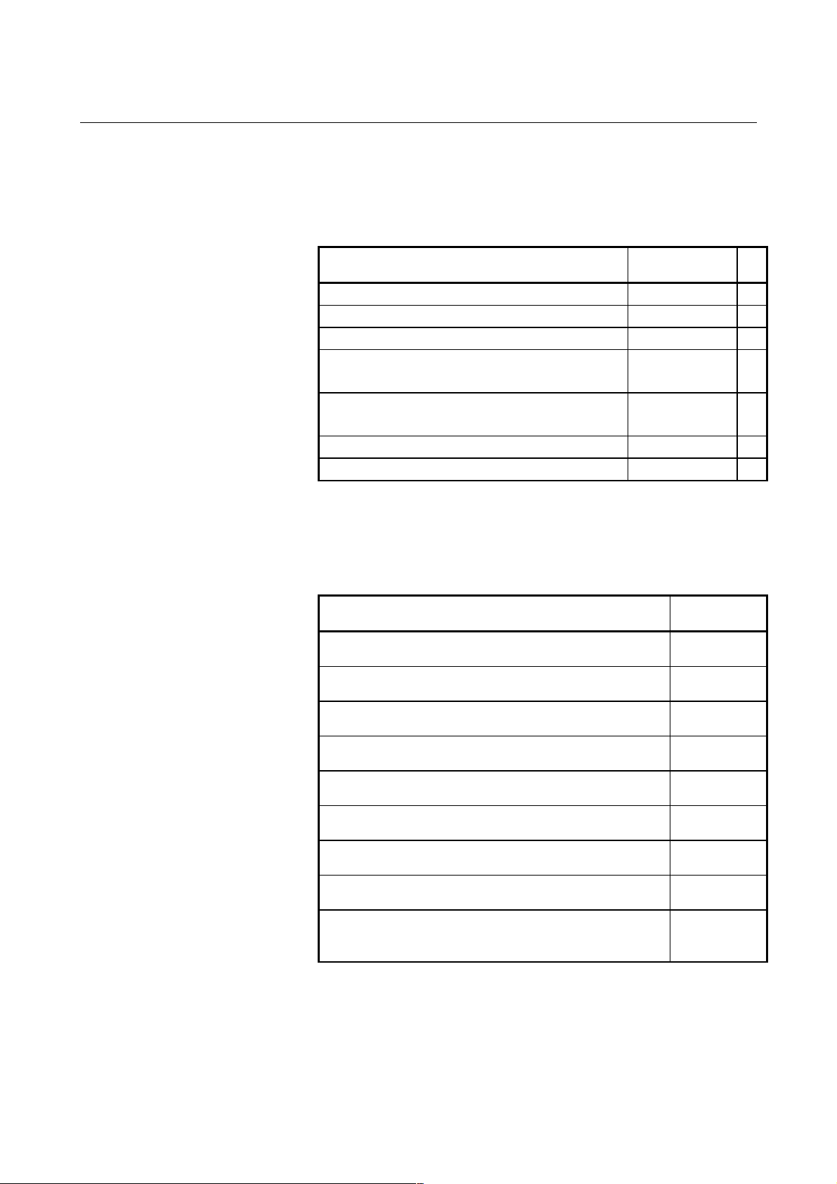
Related manuals
The following table lists the manuals related to the FANUC Series 15i,
150i. This manual is indicated by an asterisk(*).
Table 1 (a) Manuals Related to the Series 15i, 150i
Manual name Specification
number
DESCRIPTIONS B-63782EN *
CONNECTION-MBNUAL (Hardware) B-63783EN
CONNECTION-MBNUAL (Function) B-63783EN-1
OPERATOR'S-MBNUAL (PROGRAMMING)
for Machining Center
OPERATOR'S-MBNUAL (OPERATION)
for Machining Center
MAINTENANCE-MBNUAL B-63785EN
PARAMETER-MBNUAL B-63790EN
B-63784EN
B-63784EN-1
Related manuals for Servo Motor ααααi/ββββ series
The following table lists the manuals related to the FANUC Servo
Motor αi/β series.
Table 1 (b) Manuals Related to the Servo Motor ααααi/ββββ series.
Manual name Specification
FANUC AC SERVO MOTOR αi series
DESCRIPTIONS
FANUC AC SPINDLE MOTOR αi series
DESCRIPTIONS
FANUC SERVO AMPLIFIER αi series
DESCRIPTIONS
FANUC SERVO MOTOR αi series
MAINTENANCE-MBNUAL
FANUC AC SERVO MOTOR αi series
PARAMETER-MBNUAL
FANUC AC SPINDLE MOTOR αi series
PARAMETER-MBNUAL
FANUC SERVO MOTOR β series
DESCRIPTIONS
FANUC SERVO MOTOR β series
MAINTENANCE-MBNUAL
FANUC SERVO MOTOR β series
MAINTENANCE-MBNUAL
(I/O Link Option)
number
B-65262EN
B-65272EN
B-65282EN
B-65265EN
B-65270EN
B-65280EN
B-65232EN
B-65235EN
B-65245EN
- 4 -
Page 23

B-63782EN/01 GENERAL 2.LIST OF SPECIFICATIONS
2 LIST OF SPECIFICATIONS
AA: Standard
BB : Standard option
CC : Option
DD : Function included in another option
NOTE) The use of some combinations of options is restricted.
Series 15i
Item Specifications
Axis control
Controlled axes 3 axes (including axis control by PMC) AA
Maximum total controlled axes Up to 24 axes (multi-axes specification)
Up to 10 axes (standard specification)
(including two Cs axes)
Simultaneously controlled axes 2 axes AA
Simultaneously controlled axis expansion Up to maximum total controlled axes CC
Axis control by PMC Up to 8 axes CC
Cs contour control Up to 4 axes
Speed control is possible.
Axis name Optional form X, Y, Z, U, V, W, A , B, C AA
Axis name expansion Addition of I, J, K, and E CC
Controlled axis detach AA
Flexible feed gear Optional DMR AA
Optional command multiplier Use this function when flexible feed gear is not applied. CC
Parallel axes control Available on both standard type and Multi-axes type CC
Twin table function CC
Synchronous control Synchronous error compensation is possible.
Available on both standard type and Multi-axes type
Tandem control CC
Tandem disturbance elimination control Synchronous control is needed. CC
Simple synchronous control Synchronous error compensation is possible. DD
Synchronous tandem control Possible by synchronous control and tandem control DD
Dual position feedback CC
Chopping CC
Increment system IS-A,IS-B,IS-C AA
Increment system D 0.00001mm
0.00001deg
0.000001inck
Increment system E 0.000001mm
0.000001deg
0.0000001inch
Inch/metric switching CC
Interlock All axes/Each axes/Automatic operation axis/Block
start/Cutting block start
Machine lock All axes/each axes AA
Series 150i
MB
CC
CC
CC
CC
CC
AA
- 5 -
Page 24

2.LIST OF SPECIFICATIONS GENERAL B-63782EN/01
Series 15i
Item Specifications
Emergency stop AA
Overtravel AA
Stored stroke check 1 AA
Stored stroke check 2 CC
External stroke limit setting CC
Stroke limit check before travel CC
Mirror image Each axis AA
Follow-up At emergency stop and at Servo alarm and so on AA
Servo-off/mechanical handle feed AA
Position switch CC
Absolute position detection AA
Linear scale I/F with absolute address
reference mark
Feed forward for rapid traverse AA
Abnormal load detection CC
Linear motor AA
HRV control AA
Level-up HRV control AA
Fine acceleration/deceleration AA
Accuracy compensation functions
Backlash compensation AA
Separate backlash compensation for rapid
traverse and cutting feed
Smooth backlash compensation AA
Stored pitch error compensation CC
Interpolated pitch error compensation CC
Periodical secondary pitch error
compensation
Nano based error compensation Included in Interpolated pitch error compensation and
Interpolation type straightness compensation
Gradient compensation CC
Straightness deviation compensation CC
Straightness compensation at 128 points CC
Interpolation type straightness compensation CC
Bi-directional pitch error compensation CC
Pitch error compensation additional 5000
points
Three-dimensional error compensation CC
Thermal growth compensation along tool
vector
Operation
Automatic operation DNC operation (Reader/puncher interface is required)
Memory operation
MDI operation
DNC operation with memory card AA
Cycle start/Feed hold AA
Program stop/Program end AA
Reset/Rewind AA
Program number search AA
Sequence number search AA
Sequence number collation stop AA
Series 150i
MB
CC
AA
CC
DD
CC
CC
AA
- 6 -
Page 25

B-63782EN/01 GENERAL 2.LIST OF SPECIFICATIONS
Series 15i
Item Specifications
Program restart CC
Block restart CC
Tool retract & recover CC
Active block cancel CC
Buffer register AA
Multi buffer (5 blocks) AA
Multi buffer (15 blocks) CC
Multi buffer (100 blocks) CC
Dry run AA
Single block AA
Jog feed AA
Manual reference position return AA
Reference position return setting without dog AA
Reference position shift Same as “Adjustment for reference return deceleration
limit” in 15B
Manual handle feed (1 unit) CC
Manual handle feed (2 or 3 units) CC
Manual handle feed magnification Including manual handle
×1, ×10, ×M, ×N
M, N : Up to 2000
Manual handle interrupt CC
Three-dimensional handle feed CC
Control point compensation of tool length
compensation along tool axis
Manual interruption of three-dimensional
coordinate system conversion
Incremental feed ×1, ×10, ×100, ×1000, ×10000, ×100000 AA
Automatic/manual simultaneous operation CC
Manual arbitrary angle feed Unit of angle : 1/16 deg. CC
Manual numeric command CC
Recovery of manual intervention amount AA
Interpolation functions
Positioning G00 (Linear interpolation type positioning enabled) AA
Single direction positioning G60 CC
Exact stop mode G61 AA
Tapping mode G63 AA
Cutting mode G64 AA
Exact stop G09 AA
Linear interpolation AA
Circular interpolation AA
Dwell Dwell in seconds and dwell in revolution (It is possible
Helical interpolation (Circular interpolation) +
Helical interpolation B (Circular interpolation) +
Involute interpolation Involute interpolation by linear and rotary axis is
Helical involute interpolation CC
Spline interpolation Same as “Spline interpolation B” in 15-B CC
Included in Three-dimensional handle feed DD
with thread cutting option)
(Linear interpolation for up to 2 axes)
(Linear interpolation for up to 4 axes)
possible
Series 150i
MB
AA
DD
CC
AA
CC
CC
CC
- 7 -
Page 26

2.LIST OF SPECIFICATIONS GENERAL B-63782EN/01
Series 15i
Item Specifications
Threading/Feed per revolution Equal lead thread cutting, inch thread cutting,
continuous thread cutting
Arbitrary spindle gear ratio thread cutting Included in “Thread cutting, per revolution feed”. DD
Polar coordinate interpolation CC
Cylindrical interpolation CC
Cutting point interpolation for cylindrical
interpolation
Exponential interpolation CC
Hypothetical axis interpolation CC
Spiral/conical interpolation CC
Three-dimensional circular interpolation CC
Reference position return G27, G28, G29 AA
2nd reference position return CC
3rd/4th reference position return CC
Floating reference position return CC
Normal-direction control CC
Index table indexing CC
Multiple rotary axis control CC
Smooth interpolation CC
NURBS interpolation CC
General purpose retract CC
Feed functions
Rapid traverse 240m/min(1 µm) AA
Rapid traverse 99m/min(0.1 µm) AA
Rapid traverse 9.9m/min(0.01 µm) Included in “Least input increment D” DD
Rapid traverse 0.99m/min(0.001 µm) Included in “Least input increment E” DD
Rapid traverse override F0, Fm, 50%, 100% AA
Rapid traverse override 1% 0 to 100% (1%step) AA
Feed per minute mm/min AA
Feed per rotation Included in “Thread cutting, per revolution feed”. DD
Feed per rotation without position coder Included in “Thread cutting, per revolution feed”. DD
Constant tangential speed control AA
Cutting feedrate clamp AA
Automatic acceleration/deceleration Rapid traverse : Linear or exponential
Linear acceleration/deceleration after cutting
feed interpolation
Bell-shaped acceleration/deceleration after
cutting feed interpolation
Bell-shaped acceleration/deceleration after
rapid traverse interpolation
Feedrate override 0 to 254% (1%step) AA
2nd feedrate override 0 to 254% (1%step)
Feed by F with one digit CC
Inverse time feed CC
Jog override 0 to 655.34% (0.01%step) AA
Override cancel AA
External deceleration CC
Feed stop CC
Included in “Cylindrical interpolation”. DD
Cutting feed : Linear or exponential
0 to 655.34% (0.01%step)
Series 150i
MB
CC
AA
AA
CC
AA
CC
- 8 -
Page 27

B-63782EN/01 GENERAL 2.LIST OF SPECIFICATIONS
Series 15i
Item Specifications
Automatic feedrate control by area CC
Look-ahead acceleration/deceleration before
interpolation
Cutting point feedrate control Included in “Automatic corner override”. DD
Advanced preview control AA
Look-ahead bell-shaped
acceleration/deceleration before interpolation
Acc/dec before interpolation of linear type
rapid
Time constant change of bell-shaped
acceleration/ deceleration
Optimum torque acceleration/deceleration CC
Nano interpolation AA
Fine HPCC CC
Fine HPCC smooth velocity control Included in “Fine HPCC”. DD
Jerk control CC
Program input
Program code Automatic recognition of EIA and ISO AA
Program format Word address format AA
Label skip AA
Parity check Horizontal parity, vertical parity AA
Control in/out AA
Optional block skip 1 block AA
Additional optional block skip 9 blocks CC
Maximum value ±9 digit (±12 digit for R, I, J, K) AA
Program number/Program name Program number : O with 8 digits
Program name : 16 characters
Sequence number N with 8 digits AA
Absolute/incremental programming AA
Decimal point input, pocket calculator type
decimal point input
Input unit (10 times) AA
Diameter/radius programming AA
Programmable diameter/radius switching AA
Plane selection G17, G18, G19 AA
Plane switching CC
Rotary axis designation AA
Rotary axis roll-over AA
Polar coordinate command CC
Workpiece coordinate system setting G92 AA
Workpiece coordinate system preset G92.1 AA
Local coordinate system setting G52 AA
Machine coordinate system G53 AA
Workpiece coordinate system G54 to G59 AA
Addition of workpiece coordinate systems 48 sets CC
Manual absolute on/off AA
Optional-angle chamfering/corner rounding CC
Programmable data input G10, tool offset amount , workpiece zero point offset
amount can be changed by programming
Programmable parameter input CC
Series 150i
MB
AA
AA
AA
AA
AA
AA
CC
- 9 -
Page 28

2.LIST OF SPECIFICATIONS GENERAL B-63782EN/01
Series 15i
Item Specifications
Main program/sub program Sub program : 10 folds nested AA
External device subprogram call function AA
Custom macro Common variable : 600 CC
Addition to custom macro common variables :
total 900
Interrupt-type custom macro CC
Canned cycle CC
Arc radius R programming AA
Automatic corner override CC
Feedrate clamp by arc radius AA
Scaling CC
Coordinate system rotation CC
Three-dimensional coordinate conversion CC
Axis switching CC
Programmable mirror image CC
Figure copy CC
Retrace CC
Macro Executor Capacity of user program : 256KB CC
Macro executor +C language executor CC
Custom software size for Main-CPU 6MB CC
Machining type in HPCC screen programming AA
Miscellaneous/spindle functions
Miscellaneous function M with 8 digits, binary output AA
Second auxiliary function M with 8 digits Select address from A, B, C, U, V, W so
that it does not duplicate with control axis address)
Second auxiliary function with a decimal point Included in “Second auxiliary function” DD
Miscellaneous function lock AA
High-speed M/S/T/B interface AA
Multiple miscellaneous-function commands CC
Spindle function S with 8 digits, binary output AA
Spindle serial output Four spindle output is available CC
Spindle analog output Available to use with Spindle serial output CC
Constant surface speed control CC
Actual spindle speed output Included in “Spindle serial output” and “Spindle analog
output”
Spindle speed fluctuation detection CC
Spindle orientation CC
Spindle output switching CC
Spindle positioning CC
Rigid tapping Orientation, pecking cycle and return speed override
function is also possible
Tool functions, tool compensation functions
Tool function T with 8 digits, binary output AA
Tool compensation data, 32 items AA
Tool compensation data, 99 items CC
Tool compensation data, 200 items CC
Tool compensation data, 499 items CC
Tool compensation data, 999 items CC
Tool offset memory A Common with all tool offset AA
Tool offset memory B Separate memory for geometry and wear CC
Series 150i
MB
CC
CC
DD
CC
- 10 -
Page 29

B-63782EN/01 GENERAL 2.LIST OF SPECIFICATIONS
Series 15i
Item Specifications
Tool offset memory C Separate memory for geometry and wear
Separate memory for length compensation and cutter
compensation
Tool length compensation AA
Tool offset CC
Cutter compensation Same as “Cutter compensation C” in 15B CC
Three-dimensional cutter compensation CC
Cutter compensation for rotary table CC
Three-dimensional cutter compensation for
rotary table
Three-dimensional cutter compensation at
tool center point
Tool life management Time/number of cycle CC
Addition to tool life management sets (512
sets)
Addition to tool life management sets (1024
sets)
Incremental offset AA
Three-dimensional tool offset CC
Tool offset selection by T code CC
Tool offset value digit expansion AA
Tool length compensation in tool axis
direction
Tool center point control CC
Control point compensation of tool length
compensation along tool axis
Tool center point control for 5-axis machining CC
Tilted working plane command CC
Rotary table dynamic fixture offset CC
Designation direction tool length
compensation
Grinding wheel wear compensation CC
Tool length compensation in tool axis
direction with twin table control
Measurement function
Manual tool length measurement Same as “Tool length measurement” in 15B AA
Automatic tool length measurement CC
Skip function G31, Plural axes can be commanded CC
High-speed skip signal input 8 points CC
High-speed measuring position reach signal
input
Multi-step skip function CC
Tool length workpiece zero point
measurement
Workpiece zero point manual setting AA
Torque-limit skip Included in “Skip function” DD
Function for hobbing machine
Electronic gear box CC
2-axes electronic gear box Included in “Electronic gear box” DD
Electronic gear box automatic phase
synchronization
Included in tool length compensation in tool axis
direction or tool center point control
Tool length compensation in tool axis direction and
twin table function are needed.
Signal an be output to PMC CC
Included in “Electronic gear box” DD
Series 150i
MB
CC
CC
CC
CC
CC
CC
DD
CC
DD
CC
- 11 -
Page 30

2.LIST OF SPECIFICATIONS GENERAL B-63782EN/01
Series 15i
Item Specifications
Automatic exact stop check CC
Skip for EGB axis CC
Editing
Part program storage length 80m (32Kbytes) AA
Part program storage length 160m (64Kbytes) CC
Part program storage length 320m
(128Kbytes)
Part program storage length 640m
(256Kbytes)
Part program storage length 1280m
(512Kbytes)
Part program storage length 2560m
(1024Kbytes)
Part program storage length 5120m
(2048Kbytes)
Registered 100 programs AA
Expanded Registered programs CC
Part program storage editing AA
Key and program encryption CC
Back ground editing AA
Expanded part program editing AA
Play back CC
Machining time stamp CC
2 programs displaying and editing
synchronously
Setting, display
Status display AA
Clock function AA
Current position display AA
Program display 16-character program name AA
Program name 48 characters CC
Parameter setting display AA
Input/output device setting screen Included in “Reader/puncher interface” DD
Self-diagnosis function AA
Alarm display AA
Alarm history display AA
Operation history display AA
Help function Display unit with graphic display function is required. AA
Remote diagnosis function AA
Run time and parts number display AA
Actual machining speed display AA
Floppy Cassette directory display Included in “Reader/puncher interface” DD
Directory display / punch for each group AA
Tool path drawing Same as “Graphic display” in 15B CC
Background drawing CC
Servo adjustment screen AA
Spindle adjustment screen Included in “Spindle serial output” and “Spindle analog
output”
Waveform diagnosis screen Display unit with Graphic display function is needed. AA
Load meter display AA
Series 150i
MB
CC
CC
CC
CC
CC
AA
DD
- 12 -
Page 31

B-63782EN/01 GENERAL 2.LIST OF SPECIFICATIONS
Series 15i
Item Specifications
Fine torque sensing Display unit with Graphic display function is needed. CC
Hardware/software system configuration
display
NC format guidance Included in “Help function” AA
Sub screen Display unit with Graphic display function is needed. AA
Menu switch CC
Software operator's panel CC
Display language switching (English) AA
Display language switching (Japanese) AA
Display language switching (German) Included in “Display language switching A” CC
Display language switching (French) Included in “Display language switching A” CC
Display language switching (Italian) Included in “Display language switching A” CC
Display language switching (Spanish) Included in “Display language switching B” CC
Display language switching (Swedish) Included in “Display language switching B” CC
Display language switching (Chinese) Included in “Display language switching B” CC
Data protection key 3 types AA
Calculation key AA
Erase screen display/screen saver AA
Internal position compensation data display AA
Maintenance information display AA
Touch panel CC
Periodic maintenance screen AA
High-speed and high precision setting screen AA
DO signal output by softkey CC
Data input/output
Reader/punch interface A CC
Reader/punch interface B CC
Reader/punch interface C CC
Remote buffer CC
External I/O device control CC
Modem card control AA
Analog input Included in “NC window” DD
External data input/output Input/output of tool offset amount, workpiece zero
offset amount, machine zero offset amount, alarm
message, operator message, program number search,
sequence number search are available
External workpiece number search 31 points CC
FANUC Handy File CC
Memory card interface AA
Data server CC
Data server buffer mode CC
Fast data server CC
Screen hard copy function Display unit with graphic display function is required. AA
Power mate CNC manager CC
Network
Ethernet Ethernet board is needed. CC
Fast Ethernet Fast Ethernet board is needed. CC
PROFIBUS-DP Master/Slave CC
DeviceNet Master/Slave CC
Series 150i
MB
AA
CC
- 13 -
Page 32

2.LIST OF SPECIFICATIONS GENERAL B-63782EN/01
Series 15i
Item Specifications
Others
Status output signal NC ready, servo ready, rewinding, NC alarm,
distribution completion, automatic operation,
automatic operation start, automatic operation halt,
reset, in-position, rapid traverse, tapping, threading,
etc.
Axis moving signal Axis moving signal output, Axis moving direction signal
output
Key input form PMC CC
NC window CC
NC window B Included in “NC window” DD
PMC system
Machine interface (I/O Link)
Maximum DI/DO points: 1024/1024
PMC-NB6 Basic instruction: 0.085 µs/step
Program memory : Max. 32,000 step
C language
Up to 2MB (PMC-NB6 required) CC
Expanded non-volatile memory 64KB CC
Operator's panel I/O module BB
Connector panel I/O module BB
Power magnetics cabinet I/O module BB
I/O Unit-MODEL A BB
I/O Unit-MODEL B BB
Series 150i
MB
AA
CC
AA
2-slot W : 112 mm / H : 380mm / D : 172mm BBControl unit
dimensions
Manual pulse generator CC
Pendant-type manual pulse generator With axis selection switch and magnification selection
Handy machine operator’s panel CC
Applicable servo motor
Applicable servo amplifier
Separate position detector interface unit (for
closed control)
Applicable spindle motor
Applicable spindle amplifier
Multi-tap transformer 200/220/230/240/380/415/440/460/480/550VAC CC
Power supply 200 to 240VAC +10%-15%
4-slot W : 224 mm / H : 380mm / D : 172mm BB
9.5” monochrome LCD (stand-alone type) BBDisplay unit
10.4” color LCD (stand-alone type) BB
Stand-alone type MDI (vertical) BBMDI unit
Stand-alone type MDI (horizontal) BB
CC
switch
FANUC servo motor αi series and α series (with serial
interface pulse coder)
FANUC servo amplifier αi series and α series
(FSSB interface)
For separate pulse coder /Linear optical scale
2-phase pulse interface for separate pulse coder/linear
optical scale
FANUC spindle motor αi series and α series, etc.
FANUC servo amplifier αi series and α series
Analog interface AA
50 to 60HZ ±3HZ
AA
AA
CC
AA
AA
AA
- 14 -
Page 33

B-63782EN/01 GENERAL 2.LIST OF SPECIFICATIONS
Software of personal computer part in case of the CNC system which is 150i or
connected with personal computer via HSSB(High Speed Serial Bus)
Items Specifications Remarks
Operating system Windows® 2000 *1
Extended library FOCAS1 *4
Software packages
Development tools Visual C++
CNC basic operation package Option
Milling animation function Option
CNC screen display function Option
Ladder editing package Option
DNC operation management
package
Machining status monitor package Option
Visual Basic
®
®
Option
*1*1Microsoft Corp.
Microsoft Corp.
Hardware of HSSB(High Speed Serial Bus) and Required hardware of
commercially available personal computer in case of the CNC system which is
connected with the personal computer via HSSB(High Speed Serial Bus).
Items Specifications Remarks
CNC side interface board
Personal computer side interface
board
Connecting cable Optical fiber cable Max. length: 100m
Personal computer requirements CPU: Pentium® or more
ISA Bus and HSSB for 1 channel For ISA slot in the personal
computer
Using voltage: +5V only
ISA Bus and HSSB for 2 channel
PCI Bus and HSSB for 1 channel For PCI slot in the personal
computer
Using voltage: +5V only
PCI Bus and HSSB for 2 channel
For environmental
ISA slot or PCI slot 1 or more
(By selectable personal computer side interface
board)
requirements of the personal
computer, refer to the manual
supplied with the machine.
- 15 -
Page 34

2.LIST OF SPECIFICATIONS GENERAL B-63782EN/01
Hardware of CNC Display Unit with Personal Computer Function used in 150i
Items Specifications Remarks
CPU Pentium® III,
Celeron
MMX Pentium
Main memory Max. 128MBytes
Hard disk 10GBytes
Monitor
Ports PCMCIA x1 slot
CNC interface High-Speed Serial Bus
Extension slot PCI spec. extension slot
Ambient temperature of unit
Ambient relative humidity Normally: 10% to 75%RH or less (No dew, nor frost allowed)
10.4" color TFT LCD (640×480 dots),
12.1" color TFT LCD (800×600 dots),
or 15.0" color TFT LCD (1024×768
dots)
Touch panel Option
Full keyboard x1/Mouse x1
Serial (RS-232C) x2/Parallel x1
Floppy disk x1
USB×2
(Optical fiber cable)
(Short card size) x2
At operating: 5°C to 45°C
At nonoperating: -20°C to 60°C
Short term (within one month): 10% to 90%RH or less
(No dew, nor frost allowed)
Wet humidity: 29°C or less
TM
,
®
*1
Display Max. 65536 colors
Several models limited to Max. 4096
colors *2 *5
Touch panel is connected to serial port 1.
Max. length: 100m
*3
(Note)
*1: Intel, Pentium are registered trademarks of Intel Corporation.
Celeron is the trademark of Intel Corporation.
Microsoft, Windows, Visual C++, Visual Basic are registered
trademarks of Microsoft Corporation.
Each companie's name and product's name is the trademark or
registered trademark.
*2 : A special driver is necessary to display 16 or more colors.
*3 : Extension Board for IBM PC should be prepared by MTB.
*4 : FOCAS1 = FANUC Open Cnc API Specifications version 1
*5 : LCD is manufactured by using high precision technology,
however it has points which are always bright or dark.
This phenomenon is caused by LCD's structure, and not defects.
- 16 -
Page 35

II NC FUNCTIONS
Page 36

Page 37

B-63782EN/01 NC FUNCTIONS PREFACE
PREFACE
This part describes the functions that can be performed on all models.
For the functions available with each model, see the list of
specifications in Part I.
- 19 -
Page 38

1.CONROLLED AXES NC FUNCTIONS B-63782EN/01
1 CONROLLED AXES
- 20 -
Page 39

B-63782EN/01 NC FUNCTIONS 1.CONROLLED AXES
1.1 CONTROLLED AXES
Item Standard type Multiple axes type
No. of basic controlled
axes
Controlled axes
expansion (total)
Basic simultaneously
controlled axes
Simultaneously
controlled
axes expansion (total)
PMC axis control Up to Max. control axes (Cs axis is disabled.)
Max. 10 axes (Cs axis is 2
axes)
Up to Max. controlled axes
Simultaneously all axes :
Positioning, linear interpolation, jog feed (specified
axes only), and incremental feed
3 axes (2 axes)
Max. 24 axes
2 axes
- 21 -
Page 40

1.CONROLLED AXES NC FUNCTIONS B-63782EN/01
1.2 AXIS NAME
Names of axes can be optionally selected from X, Y, Z, A, B, C, U, V,
and W. They can be set by parameter.
Explanation
- Axis name expansion function
With the optional axis name expansion function, I, J, K, and E can also
be used as axis names.
When I, J, K, and E are used as the names of axes, these addresses have
the following functions and restrictions:
(1) These addresses are addresses for coordinate words.
Example) G17I-K- ; The I-K plane is selected.
(2) The numeric values to be specified must consist of up to 8 or 9
digits.
(3) A decimal point can be input.
If a decimal point is omitted, its position is determined according
to the increment system of the axis for that address.
(4) A signed value can be input.
Example) G01 E-10.5 F100;
Limitation
- Axis name expansion function
When I, J, K, and E are used as axis names, they cannot be used for the
ordinary purposes listed below.
Address
I,J,K
K G06.2
E
G code or
variable
G02
G03
G41
G42
G76
G87
G22 Stroke limit coordinates Stroke limit coordinates
G65
G66
G66.1
G33
#4108
Center position of an arc
Three- dimensional offset
vector
Canned cycle shift amount
Argument Argument
Knot value when NURBS
interpolation
Screw pitch
(number of thread for inch
screws)
Macro variable, address E
continuous-state information
Normal use Used for controlled axes Remarks
Coordinate words for I, J, andKUse an R command to specify
the center.
Coordinate words for I, J, andKThree- dimensional tool
compensation is disabled.
Coordinate words for I, J, andKAn amount of shift cannot be
specified.
A limit position cannot be
specified.
The position of the decimal
point is determined by the
increment system.
The number of threads for
E-axis coordinate word
E-axis coordinate word
No meaning
inch screws cannot be
specified in G33 threading.
The number of threads for
inch screws cannot be
specified in G33 threading.
Custom macro variable
#4108 is unavailable.
CAUTION
When this function is used, the second auxiliary
function cannot be used.
- 22 -
Page 41
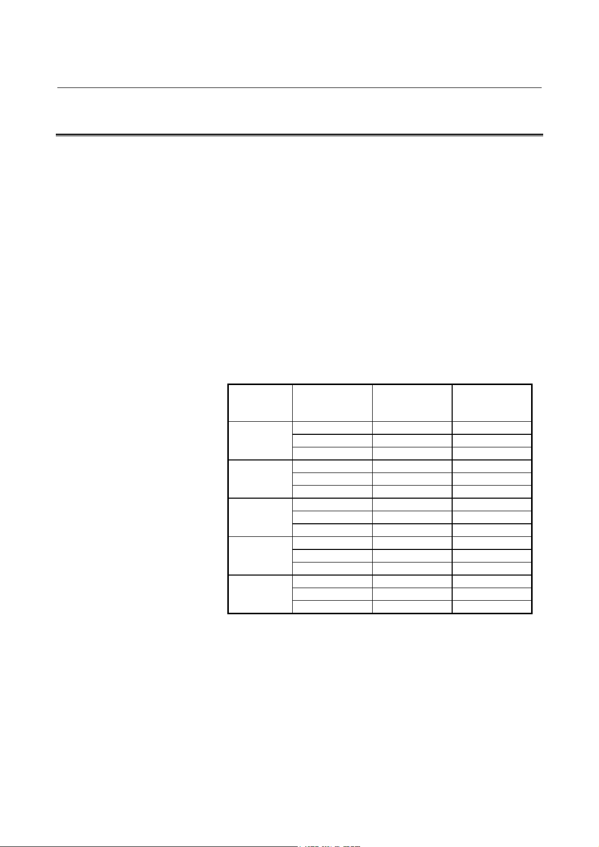
B-63782EN/01 NC FUNCTIONS 1.CONROLLED AXES
1.3 INCREMENT SYSTEM
The increment system uses least input increment (for input) and least
command increment (for output). The least input increment is the least
increment for programming the travel distance. The least command
increment is the least increment for moving the tool on the machine.
Both increments are represented in mm, inches, or deg.
There are five types of increment systems, as shown in Table1.3 (a).
One of the five types can be set for each axis by using bits 0 (ISA), 1
(ISC), 2 (ISD), and 3(ISE) of Parameter No. 1012.
The least input increment is in either metric or inch units. One can be
selected using a G code (G20, G21) or setting parameter.
The least command increment is in either metric or inch units
depending on the machine tool. Set metric or inch in bit 1 (INM) of
parameter No. 1002 in advance.
The metric and inch systems cannot be used together. There are
functions that cannot be used for axes with different unit systems
(circular interpolation, cutter compensation, and so forth).
IS-D and IS-E are optional.
Name of
increment
system
IS-A
IS-B
IS-C
IS-D
IS-E
Table1.3 (a) Increment system
Least input
increment
0.01 mm 0.01 mm 999999.99 mm
0.001 inch 0.001 inch 99999.999 inch
0.01 deg 0.01 deg 999999.99 deg
0.001 mm 0.001 mm 99999.999 mm
0.0001 inch 0.0001 inch 9999.9999 inch
0.001 deg 0.001 deg 99999.999 deg
0.0001 mm 0.0001 mm 9999.9999 mm
0.00001 inch 0.00001 inch 999.99999 inch
0.0001 deg 0.0001 deg 9999.9999 deg
0.00001 mm 0.00001 mm 9999.99999 mm
0.000001 inch 0.000001 inch 999.999999 inch
0.00001 deg 0.00001 deg 9999.99999 deg
0.000001 mm 0.000001 mm 999.999999 mm
0.0000001 inch 0.0000001 inch 99.9999999 inch
0.000001 deg 0.000001 deg 999.999999 deg
Least command
increment
Maximum stroke
- 23 -
Page 42

1.CONROLLED AXES NC FUNCTIONS B-63782EN/01
By setting bit 0 (IM0) of parameter No. 1013 for ten-fold input unit,
each increment system is set as shown in Table1.3 (b).
Table1.3 (b)
Name of
increment
system
IS-B
IS-C
IS-D
IS-E
Least input
increment
0.01 mm 0.001 mm 99999.999 mm
0.001 inch 0.0001 inch 9999.9999 inch
0.01 deg 0.001 deg 99999.999 deg
0.001 mm 0.0001 mm 9999.9999 mm
0.0001 inch 0.00001 inch 999.99999 inch
0.001 deg 0.0001 deg 9999.9999 deg
0.0001 mm 0.00001 mm 9999.99999 mm
0.00001 inch 0.000001 inch 999.999999 inch
0.0001 deg 0.00001 deg 9999.99999 deg
0.00001 mm 0.000001 mm 999.999999 mm
0.000001 inch 0.0000001 inch 99.9999999 inch
0.00001 deg 0.000001 deg 999.999999 deg
Least command
increment
Maximum stroke
- 24 -
Page 43

B-63782EN/01 NC FUNCTIONS 1.CONROLLED AXES
1.4 MAXIMUM STROKE
Maximum stroke = Least command increment times 99999999
(For IS-D and IS-E, 999999999)
See 1.3 Increment System.
NOTE
1 A command exceeding the maximum stroke cannot
be specified.
2 The actual stroke depends on the machine tool.
- 25 -
Page 44

2.PREPARATORY FUNCTION (G FUNCTION)NC FUNCTIONS B-63782EN/01
2 PREPARATORY FUNCTION (G FUNCTION)
G codes on the Table2 is prepared.
- 26 -
Page 45

B-63782EN/01 NC FUNCTIONS2.PREPARATORY FUNCTION (G FUNCTION)
Table2 G code list
Code Group Function
G00 Positioning
G01 Linear interpolation
G02 Circular interpolation/Helical interpolation CW
G03 Circular interpolation/Helical interpolation CCW
G02.2 Involute interpolation CW
G03.2 Involute interpolation CCW
G02.3 Exponential interpolation CW
G03.3 Exponential interpolation CCW
G02.4 Three-dimensional circular interpolation
G03.4 Three-dimensional circular interpolation
G06.1 Spline interpolation
G06.2
G04 Dwell
G05.1 Multi-buffer
G07 Hypothetical axis interpolation
G07.1 Cylindrical interpolation
G09 Exact stop
G10 Programmable data input
G10.1 PMC data setting
G10.6 Tool retract & recover
G10.9 Programmable diameter/radius specification switching function
G11
G12.1 Polar coordinate interpolation mode
G13.1
G15 Polar coordinates command cancel
G16
G17 XpYp plane where, Xp: X axis or a parallel axis
G18 ZpXp plane Yp:Y axis or a parallel axis
G19
G20 Inch input
G21
G22 Stored stroke check function on
G23
G25 Spindle speed fluctuation detection off
G26
G27 Reference position return check
G28 Automatic return to reference position
G29 Automatic return from reference position
G30 Return to 2nd, 3rd, or 4th reference position
G30.1 Return to floating reference position
G31 Skip function
G31.1 Multistage skip function 1
G31.2 Multistage skip function 2
G31.3 Multistage skip function 3
G31.4 Multistage skip function 4
G31.8 EGB skip function
G31.9
01
00
26
17
02
06
04
25
00
NURBS interpolation
Programmable data input mode cancel
Polar coordinate interpolation cancel mode
Polar coordinates command
YpZp plane Zp: Z axis or a parallel axis
Metric input
Stored stroke check function off
Spindle speed fluctuation detection on
High succession skip function
- 27 -
Page 46

2.PREPARATORY FUNCTION (G FUNCTION)NC FUNCTIONS B-63782EN/01
Table2 G code list
Code Group Function
G33 01 Threading
G37 Automatic tool length measurement
G38 Cutter compensation C vector retention
G39
G40 Cutter compensation cancel / Three dimensional compensation cancel
G41 Cutter compensation left / Three dimensional compensation
G42 Cutter compensation right
G41.2 Three-dimensional cutter compensation left
G42.2 Three-dimensional cutter compensation right
G41.3
G40.1 Normal direction control cancel mode
G41.1 Normal direction control left side on
G42.1
G43 Tool length compensation (+ve)
G43.1 Tool length compensation in tool axis direction
G44
G45 Tool offset increase
G46 Tool offset decrease
G47 Tool offset double increase
G48
G49 08 Tool length compensation cancel
G50 Scaling cancel
G51
G50.1 Programmable mirror image cancel
G51.1
G52 Local coordinate system setting
G53
G54 Workpiece coordinate system 1 selection
G54.1 Additional workpiece coordinate system selection
G54.2 Fixture offset selection
G55 Workpiece coordinate system 2 selection
G56 Workpiece coordinate system 3 selection
G57 Workpiece coordinate system 4 selection
G58 Workpiece coordinate system 5 selection
G59
G60 00/01 Unidirectional positioning
G61 Exact stop mode
G62 Automatic corner override
G63 Tapping mode
G64
G65 00 Macro call
G66 Macro modal call A
G66.1 Macro modal call B
G67
G68 Coordinate system rotation
G69
G72.1 Rotation copy
G72.2
00
07
19
08
00
11
18
00
14
15
12
16
00
Cutter compensation C corner rounding
Leading edge offset
Normal direction control right side on
Tool length compensation (-ve)
Tool offset double decrease
Scaling
Programmable mirror image
Machine coordinate system selection
Workpiece coordinate system 6 selection
Cutting mode
Macro modal call cancel
Coordinate system rotation cancel
Linear copy
- 28 -
Page 47

B-63782EN/01 NC FUNCTIONS2.PREPARATORY FUNCTION (G FUNCTION)
Table2 G code list
Code Group Function
G73 Peck drilling cycle
G74 Counter tapping cycle
G76 Fine boring cycle
G80
G81
G80.5 Electronic gear box synchronous cancel (Command for 2 axes)
G81.5
G81.1 00 Chopping mode on
G82 Drill cycle, counter boring
G83 Peck drilling cycle
G84 Tapping cycle
G84.2 Rigid tapping cycle
G84.3 Reverse rigid tapping cycle
G85 Boring cycle
G86 Boring cycle
G87 Back boring cycle
G88 Boring cycle
G89
G90 Absolute command
G91
G92 Setting for work coordinate system or clamp at maximum spindle speed
G92.1
G93 Inverse time feed
G94 Feed per minute
G95
G96 Constant surface speed control
G97
G98 Return to initial level in canned cycle
G99
09
09
03
00
05
13
10
Canned cycle cancel / external operation function cancel / Electronic gear box
synchronous cancel (Command for hobbing machine or 1 axis)
Drill cycle, stop boring /external operation function / Electronic gear box
synchronous start (Command for hobbing machine or 1 axis)
Electronic gear box synchronous start (Command for 2 axes)
Boring cycle
Incremental command
Workpiece coordinate system preset
Feed per rotation
Constant surface speed control cancel
Return to R-point level in canned cycle
- 29 -
Page 48

3.INTERPOLATION FUNCTION NC FUNCTIONS B-63782EN/01
3 INTERPOLATION FUNCTION
- 30 -
Page 49

B-63782EN/01 NC FUNCTIONS 3.INTERPOLATION FUNCTION
3.1 POSITIONING (G00)
Explanation
The G00 command moves a tool to the position in the workpiece
system specified with an absolute or an incremental command at a
rapid traverse rate.
In the absolute command, coordinate value of the end point is
programmed.
In the incremental command the distance the tool moves is
programmed.
Either of the following tool paths can be selected according to
parameter.
- Nonlinear interpolation positioning
The tool is positioned with the rapid traverse rate for each axis
separately. The tool path is normally straight.
- Linear interpolation positioning
The tool path is the same as in linear interpolation (G01). The tool
is positioned within the shortest possible time at a speed that is not
more than the rapid traverse rate for each axis.
Format
Linear interpolation positioning
End position
Non linear interpolation positioning
Fig.3.1 (a) Tool path
Start position
In the positioning mode actuated by G00, the tool is accelerated to a
predetermined speed at the start of a block and is decelerated at the end
of a block. Execution proceeds to the next block after confirming the
in-position.
"In-position " means that the feed motor is within the specified range.
In-position check for each block can be disabled by setting parameter
accordingly.
G00 IP_ ;
IP_ : For an absolute command, the coordinates of an
end position, and for an incremental commnad,
the distance the tool moves.
- 31 -
Page 50
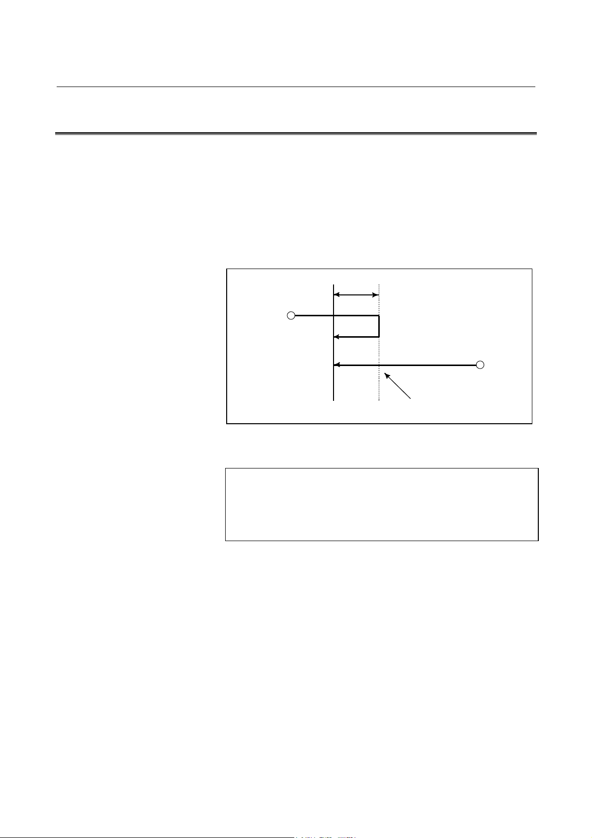
3.INTERPOLATION FUNCTION NC FUNCTIONS B-63782EN/01
3.2 SINGLE DIRECTION POSITIONING (G60)
Explanation
It is always controlled to perform positioning to the end point from a
single direction, for better precision in positioning. If direction from
start point to end point is different from the predecided direction, it
once positions to a point past the end point, and the positioning is
reperformed for that point to the end point.
Even if the direction from start point to end point is the same as
predecided direction, the tool stops once before the end point.
Overrun
Start position
Format
Start position
End position
Fig.3.2 (a) Direction positioning process
Temporary stop
G60 IP_ ;
IP_ : For an absolute command, the coordinates of an
end position, and for an incremental commnad,
the distance the tool moves.
- 32 -
Page 51
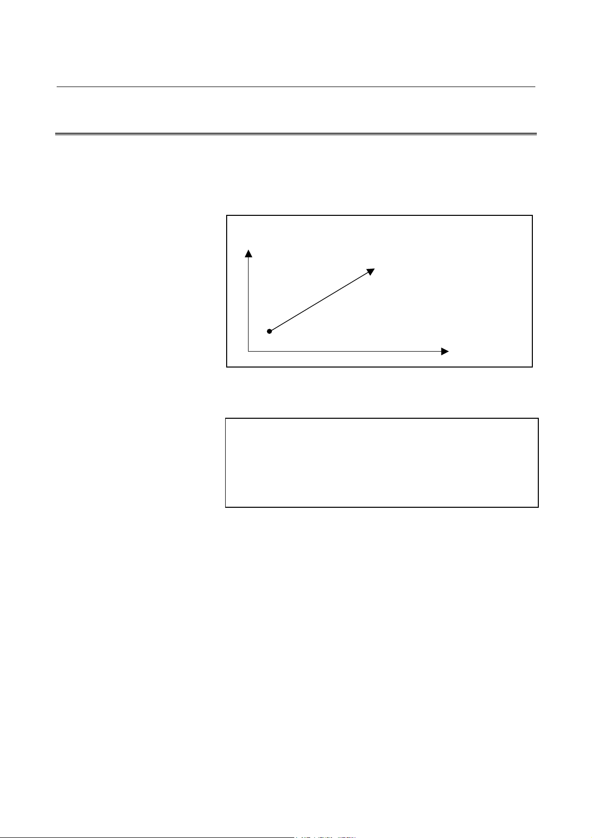
B-63782EN/01 NC FUNCTIONS 3.INTERPOLATION FUNCTION
3.3 LINEAR INTERPOLATION (G01)
A tools move along a line to the specified position at the feedrate
specified in F. The feedrate specified in F is effective until a new value
is specified. It need not be specified for each block.
Example
Format
X axis
Start point
Fig.3.3 (a) Linear interpolation
Program example)
G90 G01 X200. Y150. F200. ;
End point (200, 150)
Z axis
G01 IP_ F_ ;
IP_ : For an absolute command, the coordinates of an
end point , and for an incremental commnad, the
distance the tool moves.
F_ : Speed of tool feed (Feedrate)
- 33 -
Page 52
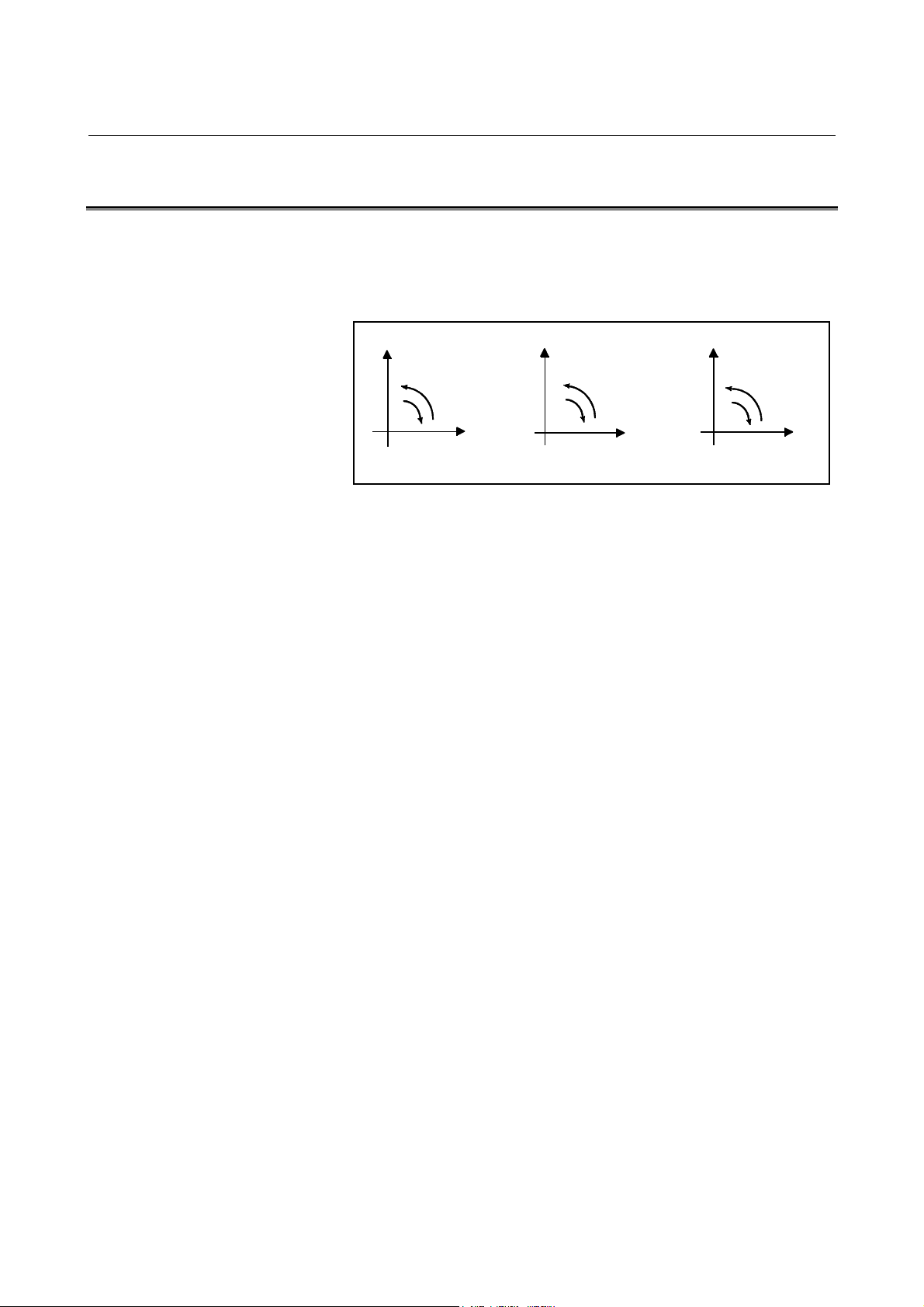
3.INTERPOLATION FUNCTION NC FUNCTIONS B-63782EN/01
3.4 CIRCULAR INTERPOLATION (G02,G03)
Circular interpolation of optional angle from 0 deg to 360 deg can be
specified.
G02: Clockwise (CW) circular interpolation
G03: Counterclockwise (CCW) circular interpolation
Yp
G03
G02
G17
Xp
Fig.3.4 (a) Direction of the circular interpolation
Xp
G02
G18
G03
Zp
G02
G19
G03
YpZp
Feed rate of the tangential direction takes the speed specified by the F
code.
Planes to perform circular interpolation is specified by G17, G18, G19.
Circular interpolation can be performed not only on the X, Y, and Z
axis but also on the parallel axes of the X, Y, and Z axes.
G17: Xp-Yp plane
G18: Zp-Xp plane
G19: Yp-Zp plane
where
Xp: X axis or its parallel axis
Yp: Y axis or its parallel axis
Zp: Z axis or its parallel axis
Parameter is set to decide which parallel axis of the X, Y, Z axes to be
the additional axis.
- 34 -
Page 53

B-63782EN/01 NC FUNCTIONS 3.INTERPOLATION FUNCTION
X
X
Format
Arc in the XpYp plane
G02 I_J_
G17 Xp_Yp_ F_ ;
G03 R_
Arc in the ZpXp plane
G02 K_I_
G18 Zp_Xp_ F_ ;
G03 R_
Arc in the YpZp plane
G02 J_K_
G19 Yp_Zp_ F_ ;
G03 R_
Z
End point (z,x)
k
Start point
i
Z
Y
Center
End point (x,y)
Y
i
Center
Fig.3.4 (b) Distance from the start point to the center of arc
Start point
j
Center
End point (y,z)
Start point
j
k
- 35 -
Page 54

3.INTERPOLATION FUNCTION NC FUNCTIONS B-63782EN/01
X
3.5 HELICAL INTERPOLATION (G02,G03)
Helical interpolation which moved helically is enabled by specifying
up to two other axes which move synchronously with the circular
interpolation by circular commands.
The basic command method involves simply adding a move command
for one or two axes, other than circular interpolation axes, to a circular
interpolation command (see II-3.4).
As the feedrate, either a feedrate tangent to an arc or a tangential
feedrate determined by also considering movement along the linear
axes can be specified. The feedrate to be specified can be selected by
setting bit 2 (HTG) of parameter No. 1401. If HTG is set to 0, a feedrate
along an arc is specified by an F command. Therefore, the feedrate on
a linear axis is as follows:
F ×
Determine the feedrate so that the linear axis feedrate does not exceed
any of the limit values
axislinearofLength
arccircularofLength
Z
Tool path
Y
The feedrate along the circumference of two
circular interpolated axes is the specified feedrate.
Fig.3.5 (a) Feedrate When Parameter HTG = 0
When bit 2 (HTG) of parameter No. 1401 is set to 1, the speed
command specifies the feedrate along the actual tool path, including
movement along the linear axis.
In this case, the feedrate along the arc on the plane is:
F+×
arccircularofLength
22
)()( axislinearofLengtharccircularofLength
The feedrate along the linear axis is:
F+×
axislinearofLength
22
)()( axislinearofLengtharccircularofLength
- 36 -
Page 55
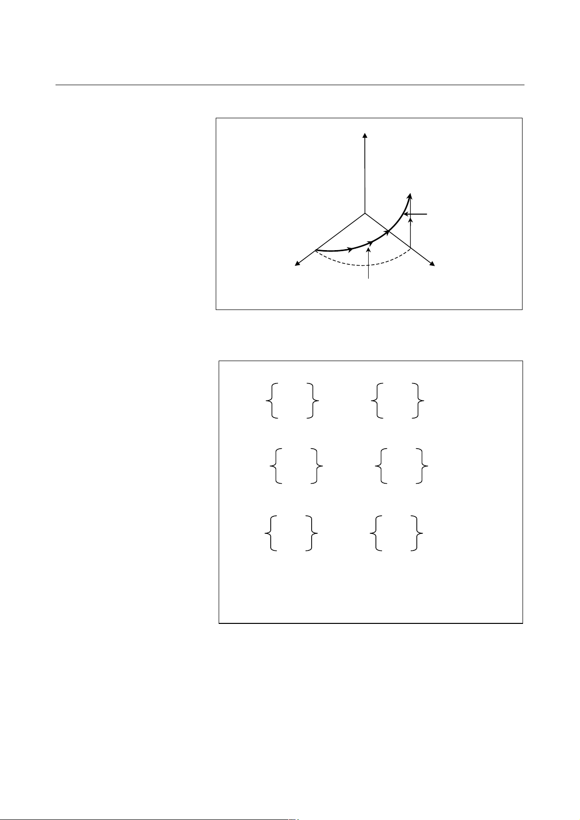
B-63782EN/01 NC FUNCTIONS 3.INTERPOLATION FUNCTION
X
Z
Tool path
Y
The speed command specifies the
feed rate along the tool path.
Fig. 3.5 (b) Feedrate When Parameter HTG = 1
Format
Synchronously with arc of XpYp plane
G02 I_ J_
G17 Xp_Yp_
αααα_ ((((ββββ_))))F_ ;
G03 R
Synchronously with arc of ZpXp plane
G02 K_ I_
G18 Zp_Xp_
αααα_ ((((ββββ_))))F_ ;
G03 R_
Synchronously with arc of YpZp plane
G02 J_ K_
G19 Yp_Zp_
αααα_ ((((ββββ_))))F_ ;
G03 R_
αααα, ββββ : Any one axis where circular interpolation is not
applied.
Up to two other axes can be specified.
- 37 -
Page 56
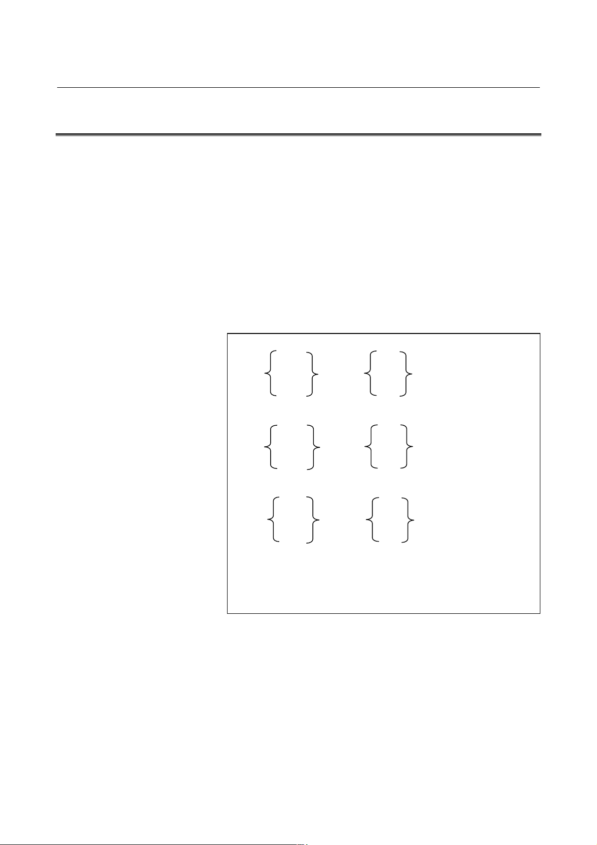
3.INTERPOLATION FUNCTION NC FUNCTIONS B-63782EN/01
3.6 HELICAL INTERPOLATION B (G02,G03)
Helical interpolation B allows the tool to move in helically. This can
be done by specifying the circular interpolation command together with
up to four axes.
The command format for helical interpolation B consists of the
command format for normal helical interpolation and move commands
for two axes. As with normal helical interpolation, the feedrate of
helical interpolation B is controlled so that the feedrate of circular
interpolation can achieve the specified feedrate. (see II-3.5)
Bit 2 (HTG) of parameter No. 1401 can be used to specify whether the
speed command specifies the feedrate along the tangential line of the
arc on the plane, or the feedrate along the tangential line of the actual
tool path, including movement along the linear axis.
Format
Synchronously with arc of XpYp plane
G02 I_J_
G17 Xp_Yp_
G03 R_
αααα_ββββ_γγγγ_δδδδ_F_ ;
Synchronously with arc of ZpXp plane
G02 K_I_
G18 Zp_Xp_
αααα_ββββ_γγγγ_δδδδ_F_ ;
G03 R_
Synchronously with arc of YpZp plane
G02 J_K_
G19 Yp_Zp_
αααα_ββββ_γγγγ_δδδδ_F_ ;
G03 R_
αααα, ββββ, γγγγ, δδδδ : Any one axis where circular interpolation is
not applied.
Up to four other axes can be specified.
- 38 -
Page 57

B-63782EN/01 NC FUNCTIONS 3.INTERPOLATION FUNCTION
3.7 POLAR COORDINATE INTERPOLATION (G12.1,G13.1)
Polar coordinate interpolation is a function that exercises contour
control in converting a command programmed in a Cartesian
coordinate system to the movement of a linear axis (movement of a
tool) and the movement of a rotary axis (rotation of a workpiece). This
function is useful for grinding a cam shaft.
Format
G12.1; Starts polar coordinate interpolation mode
(enables polar coordinate interpolation)
: Specify linear or circular interpolation using
coordinates in a Cartesian coordinate system
consisting of a linear axis and rotary axis
(virtual axis).
G13.1 Polar coordinate interpolation mode is
cancelled (for not performing polar
coordinate interpolation)
Specify G12.1 and G13.1 in Separate Blocks.
- 39 -
Page 58
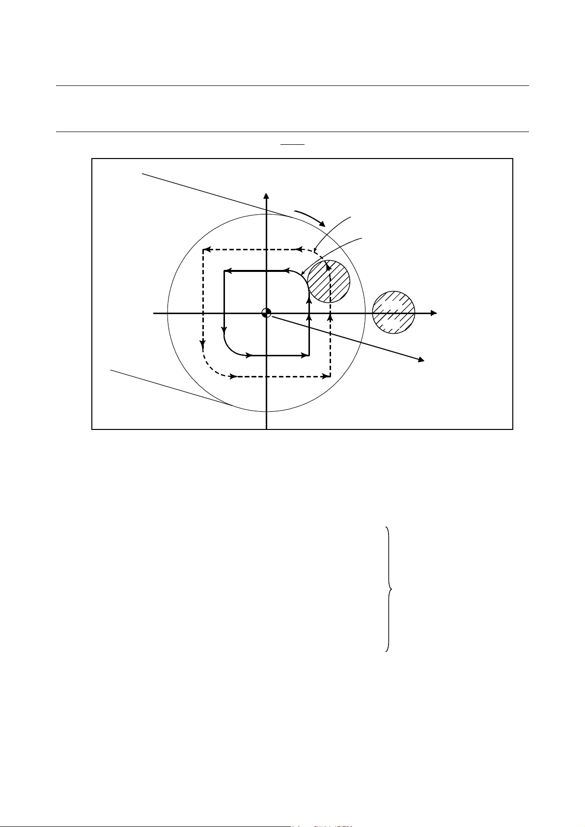
3.INTERPOLATION FUNCTION NC FUNCTIONS B-63782EN/01
Example
Example of Polar Coordinate Interpolation Program Based on X Axis(Linear Axis) and C Axis (Rotary
Axis)
C'(hypothetical axis)
C axis
N204
N205
N206
Fig.3.7 Polar Coordinate Interpolation Program Based on X Axis(Linear Axis) and C Axis (Rotary Axis)
N203
N202
N208
N207
Path after cutter compensation
Program path
N201
N200
Tool
Z axis
X-axis
O001;
:
N010 T0101
:
N0100 G90 G00 X60.0 C0 Z_; Positioning to start position
N0200 G12.1; Start of polar coordinate
N0201 G42 G01 X20.0F_;
N0202 C10.0;
N0203 G03 X10.0 C20.0 R10.0;
N0204 G01 X-20.0;
N0205 C-10.0; Geometry program
N0206 G03 X-10.0-20.0 I10.0 J0; (program based on cartesian
N0207 G01 X20.0; coordinates on X-C' plane)
N0208 C0;
N0209 G40 X60.0;
N0210 G13.1; Cancellation of polar
coordinate interpolation
N0300 Z_:
N0400 X_C_;
:
N0900M30;
- 40 -
Page 59
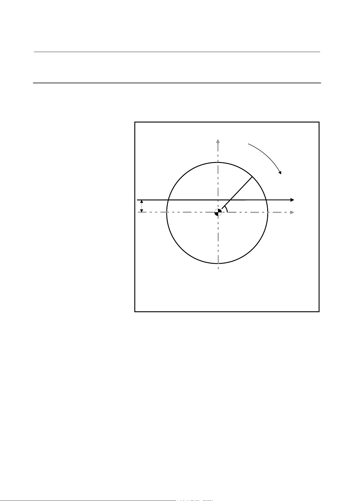
B-63782EN/01 NC FUNCTIONS 3.INTERPOLATION FUNCTION
3.7.1 Virtual Axis Direction Compensation for Polar Coordinate
Interpolation
In polar coordinate interpolation, this function compensates a machine
if it has an error on the virtual axis, that is, the center of the rotation axis
is not on the X-axis.
Virtual axis (C-axis)
C-axis
(X, C)
Error on virtual axis
Center of rotation axis
(X, C) : Point on the X-C plane
X : X coordinate on the X-C plane
C : Virtual C-axis coordinate on the
X-C plane
If, on a machine on which polar coordinate interpolation is performed
on the X-axis (linear axis) and the C-axis (rotation axis) as shown in the
figure above, there is an error on the virtual axis, this function
compensates for the error before interpolation.
X-
- 41 -
Page 60

3.INTERPOLATION FUNCTION NC FUNCTIONS B-63782EN/01
3.8 CYLINDRICAL INTERPOLATION (G07.1)
The amount of travel of a rotary axis specified by an angle is once
internally converted to a distance of a linear axis along the outer
surface so that linear interpolation or circular interpolation can be
performed with another axis. After interpolation, such a distance is
converted back to the amount of travel of the rotary axis.
The cylindrical interpolation function allows the side of a cylinder to
be developed for programming. So programs such as a program for
cylindrical cam grooving can be created very easily.
Format
G07.1 IPr ; Starts the cylindrical interpolation mode
(enables cylindrical interpolation).
:
:
G07.1 IP0 ; The cylindrical interpolation mode is
cancelled.
IP :An address for the rotation axis
r :The radius of the cylinder
Specify G07.1 IPr ; and G07.1 IP0; in separate blocks.
G107 can be used instead of G07.1.
- 42 -
Page 61

B-63782EN/01 NC FUNCTIONS 3.INTERPOLATION FUNCTION
C
Example
Example of a Cylindrical Interpolation Program
O0001 (CYLINDRICAL INTERPOLATION);
N01 G00 G90 Z100.0 C0 ;
N02 G01 G91 G18 Z0 C0 ;
N03 G07.1 C57299 ;
N04 G90 G01 G42 Z120.0 D01 F250 ;
N05 C30.0 ;
N06 G02 Z90.0 C60.0 R30.0 ;
N07 G01 Z70.0 ;
N08 G03 Z60.0 C70.0 R10.0 ;
N09 G01 C150.0 ;
N10 G03 Z70.0 C190.0 R75.0 ;
N11 G01 Z110.0 C230.0 ;
N12 G02 Z120.0 C270.0 R75.0 ;
N13 G01 C360.0 ;
N14 G40 Z100.0 ;
N15 G07.1 C0 ;
N16 M30 ;
Note) In the sample program given here, the C-axis in
parameter No. 1022 is set to 5 (an axis parallel
to the X-axis).
Z
‚C
‚R
mm
120
110
70
60
90
Z
N05
N06
N11
N07
N08
0
30
60 70
N09
N10
150
N12
230190
270
N13
360
deg
Fig.3.8 (a) Cylindrical Interpolation
- 43 -
Page 62
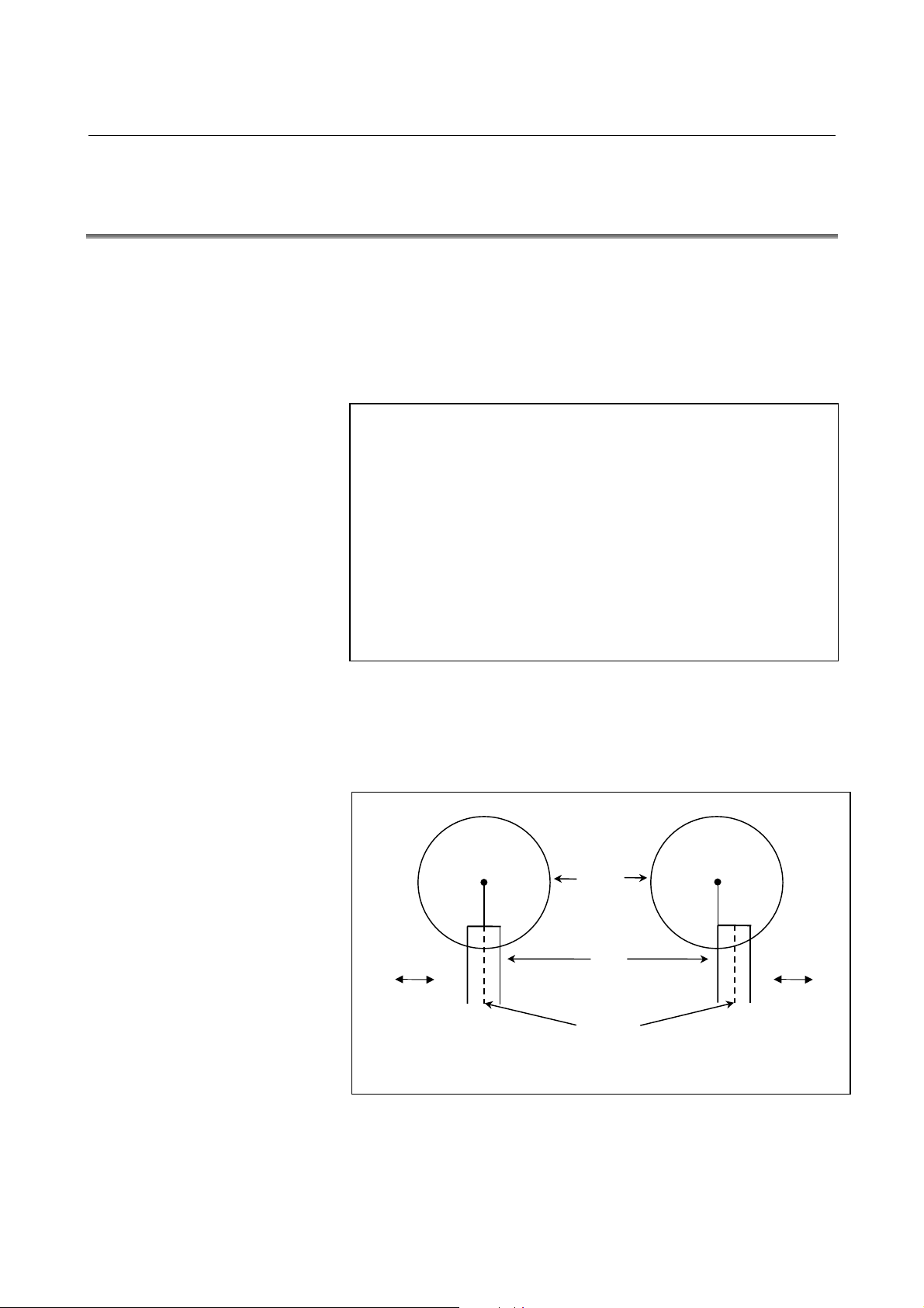
3.INTERPOLATION FUNCTION NC FUNCTIONS B-63782EN/01
3.9 CYLINDRICAL INTERPOLATION CUTTING POINT
CONTROL (G07.1)
The conventional cylindrical interpolation function controls the tool
center so that the tool axis always moves along a specified path on the
cylindrical surface, towards the rotation axis (cylindrical axis) of the
workpiece. On the other hand, this function controls the tool so that the
tangents to the tool and a contour figure cutting surface always pass
through the rotation center of a workpiece
Format
As shown below, the same command as that for the
conventional cylindrical interpolation function is
used.
G07.1 IPr ; Sets cylindrical interpolation mode
(enables cylindrical interpolation).
:
:
G07.1 IP0 ; Clears cylindrical interpolation mode.
IP : One rotation axis address
r : Cylinder radius of rotation axis
Specify each of G07.1 IPr; and G07.1 IP0; singly in a block.
Explanation
- Comparison with conventional cylindrical interpolation
As shown in Fig.3.9 (a) , control is exercised along the offset axis (Yaxis) direction that is perpendicular to the tool, tool center axis, and
workpiece rotation center axis.
Rotation
axis
Y-axis
Conventional
Fig.3.9 (a) Comparison with Conventional Interpolation
Workpiece
Tool
Tool center
Rotation
axis
Y-axis
Cylindrical interpolation based
on this function
- 44 -
Page 63

B-63782EN/01 NC FUNCTIONS 3.INTERPOLATION FUNCTION
Example
- Example of cylindrical interpolation cutting point compensation
The sample program below indicates the positional relationships
between a workpiece and tool.
O0001(CYLINDRICAL INTERPOLATION1) ;
N01 G00 G90 Z100.0 C0 ;
N02 G01 G91 G19 Z0 C0 ;
N03 G07.1 C57299 ;
N04 G01 G42 G90 Z120.0 D01 F250. ; …(1)
N05 C20.0 ; …(2)
N06 G02 Z80.0 C60.0 R40.0 ; …(3)
N07 G01 Z70.0 ; …(4)
N08 G03 Z60.0 C70.0 R10.0 ; …(5)
:
M30 ;
Z-axis
(mm)
120
(2) (3)
(1)
Fig.3.9 (b) Path of Sample Program for Cylindrical Interpolation Cutting
90
80
70
60
30
(4)
(5)
20 30
Point Compensation
60 70 ( deg )
Tool
Programmed path
Tool center path
Tool
C-axis on the cylindrical surface
Z-axis
C-axis on the
Cylindrical
surface
- 45 -
Page 64
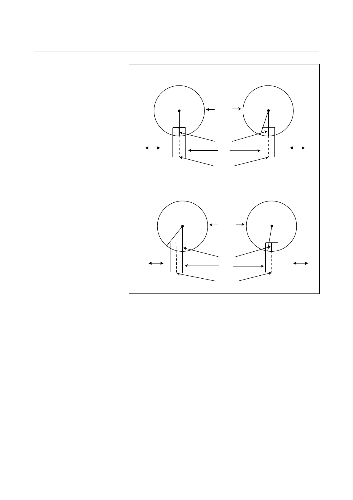
3.INTERPOLATION FUNCTION NC FUNCTIONS B-63782EN/01
Positional relationship between the
workpiece and tool of (1)
Rotation
0°
Y-axis
Positional relationship between the
workpiece and tool of (3) and (4).
Rotation
Cutting surface
Workpiece
Tool
Tool center
Workpiece
Positional relationship between the
workpiece and tool of (2)
Rotation
0°
20°
Y-axis
Positional relationship between the
workpiece and tool of (5)
Rotation
20°
60°60°
70°
Y-axis
Y-axis
Cutting surface
Tool
Tool center
Fig.3.9 (c) Positional Relationships between Workpiece and Tool of
Sample Program
- 46 -
Page 65

B-63782EN/01 NC FUNCTIONS 3.INTERPOLATION FUNCTION
A
- Example of specifying cylindrical interpolation cutting point compensation and
normal direction control at the same time
Cutter compensation value No. 01 = 30 mm
O0002(CYLINDRICAL INTERPOLATION2) ;
N01 G00 G90 X100.0 A0 ;
N02 G01 G91 G17 X0 A0 ;
N03 G07.1 C57299 ;
N04 G01 G41 G42.1 G90 X120.0 D01 F250. ;
N05 A20.0 ;
N06 G03 X80.0 A60.0 R40.0 ;
N07 G01 X70.0 ;
N08 G02 X70.0 A70.0 R10.0 ;
N09 G01 A150.0 ;
N10 G02 X70.0 A190.0 R85.0 ;
N11 G01 X110.0 A265.0 ;
N12 G03 X120.0 A305.0 R85.0 ;
N13 G01 A360.0 ;
N14 G40 G40.1 X100.0 ;
N15 G07.1 A0 ;
N16 M30 ;
Z-axis
C-axis
Fig.3.9 (d) Sample Program Specifying Cylindrical Interpolation Cutting
Point Compensation and Normal Direction Control at the
Same Time
Y-axis
X-axis
-axis
- 47 -
Page 66
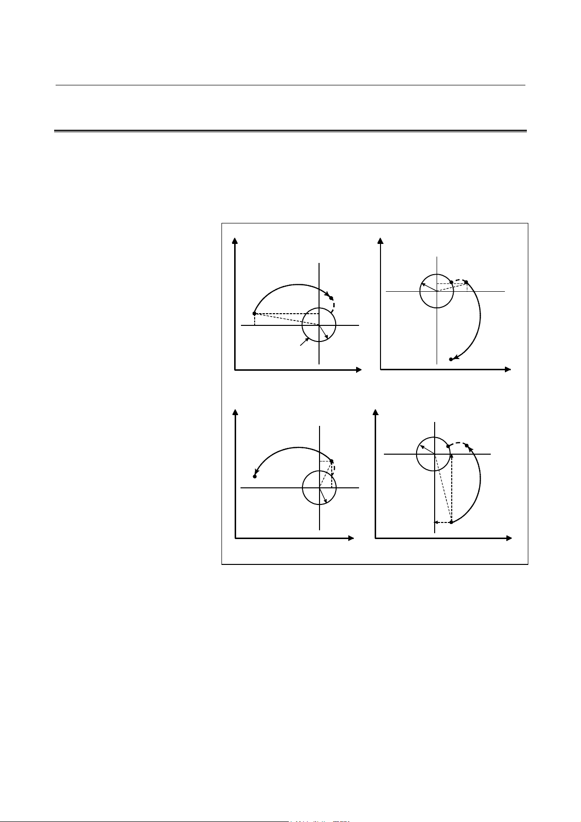
3.INTERPOLATION FUNCTION NC FUNCTIONS B-63782EN/01
R
p
)
3.10 INVOLUTE INTERPOLATION (G02.2,G03.2)
Involute curve machining can be performed by using involute
interpolation. Involute interpolation ensures continuous pulse
distribution even in high-speed operation in small blocks, thus enabling
smooth and high-speed machining. Furthermore, machining tapes can
be created easily and efficiently, reducing the required length of tape.
Yp
0
I
0
R
End point
Pe
Po
Start point
Ps
Po
J
Start
point
Yp
End
point
Ps
Pe
J
I
Base circle
Clockwise involute interpolation (G02.2)
Counterclockwise involute inter
Xp
Yp
Xp
Yp
olation (G03.2
Po
Ps
I
R
Pe
I
End point
Ro
J
Start point
Ps
J
Xp
End point
Pe
Xp
0
R
0
Fig.3.10 (a) Actual Movement
- 48 -
Page 67

B-63782EN/01 NC FUNCTIONS 3.INTERPOLATION FUNCTION
Format
Involute interpolation on the Xp-Yp plane
G17 G02.2 Xp_ Yp_ I_ J_ R_ F_ ;
G17 G03.2 Xp_ Yp_ I_ J_ R_ F_ ;
Involute interpolation on the Zp-Xp plane
G18 G02.2 Zp_ Xp_ K_ I_ R_ F_ ;
G18 G03.2 Zp_ Xp_ K_ I_ R_ F_ ;
Involute interpolation on the Yp-Zp plane
G19 G02.2 Yp_ Zp_ J_ K_ R_ F_ ;
G19 G03.2 Yp_ Zp_ J_ K_ R_ F_ ;
Where,
G02.2 : Involute interpolation (clockwise)
G03.2 : Involute interpolation (counterclockwise)
G17/G18/G19 : Xp-Yp / Zp-Xp / Yp-Zp plane selection
Xp_ : X-axis or a parallel axis
(set in parameter)
Yp_ : Y-axis or a parallel axis
(set in parameter)
Zp_ : Z-axis or a parallel axis
(set in parameter)
I_,J_,K_ : Center of the base circle for an involute
curve viewed from the start point
R_ : Base circle radius
F_ : Cutting feedrate
- 49 -
Page 68

3.INTERPOLATION FUNCTION NC FUNCTIONS B-63782EN/01
3.11 HELICAL INVOLUTE INTERPOLATION (G02.2,G03.3)
This interpolation function applies involute Interpolation to two axes
and directs movement for up to four other axes at the same time. This
function is similar to the helical function used in circular interpolation.
Format
Involute interpolation in the Xp-Yp plane,
G02.2
G17 Xp_Yp_ I_J_R_
G03.2
Involute interpolation in the Zp-Xp plane,
G02.2
G18 Zp_Xp_ K_I_R_
G03.2
Involute interpolation in the Yp-Zp plane,
G02.2
G19 Yp_Zp_ J_K_R_
G03.2
αααα_ββββ_γγγγ_δδδδ_F_ ;
αααα_ββββ_γγγγ_δδδδ_F_;
αααα_ββββ_γγγγ_δδδδ_F_ ;
αααα, ββββ, γγγγ, δδδδ : Any one axis where involute interpolation is
not applied.
Up to four other axes can be specified.
- 50 -
Page 69
B-63782EN/01 NC FUNCTIONS 3.INTERPOLATION FUNCTION
3.11.1 Involute Interpolation with a Linear Axis and Rotation Axis
(G02.2,G03.3)
In the polar coordinate interpolation mode, an involute curve can be
machined using involute interpolation. The involute curve to be
machined is drawn in the plane of the linear axis and rotation axis.
Format
When the linear axis is the X-axis or an axis parallel
to the X-axis
G02.2
X_ C_ I_ J_ R_ F_ ;
G03.2
When the linear axis is the Y-axis or an axis parallel
to the Y-axis
G02.2
Y_ C_ J_ K_ R_ F_ ;
G03.2
When the linear axis is the Z-axis or an axis parallel
to the Z-axis
G02.2
Z_ C_ K_ I_ R_ F_ ;
G03.2
G02.2 : Clockwise involute interpolation
G03.2 : Counterclockwise involute interpolation
Example) When the linear axis is the X-axis
X,C : End point linear axis coordinate of the involute
curve, rotation axis
I,J : Center position of the base circle of the involute
curve viewed from the start point
R : Radius of the base circle
F : Cutting feedrate
- 51 -
Page 70
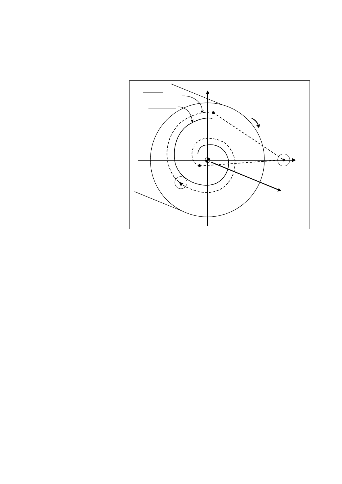
3.INTERPOLATION FUNCTION NC FUNCTIONS B-63782EN/01
Example
Path after
tool compensation
Program path
Fig.3.11.1 (a) Involute interpolation during polar coordinate interpolation
C (hypothetical axis)
N204
N202
N203
N205
N201
C-axis
Tool
X-axis
N200
Z-axis
O0001 ;
:
N010 T0101 ;
:
N100 G90 G00 X15.0 C0 Z0 ; Positioning to the start position
N200 G12.1 ; Start of polar coordinate interpolation
N201 G41 G00 X-1.0 ;
N202 G01 Z-2.0 F_ ;
N203 G02.2 X1.0 C9.425 I1.0 J0 R1.0 ;
Involute interpolation during polar coordinate interpolation
N204 G01 Z0 ;
N205 G40 G00 X15.0 C0 ;
N206 G13.1 ; Polar coordinate interpolation cancel
N300 Z_ ;
N400 X_ C_ ;
:
M30 ;
- 52 -
Page 71
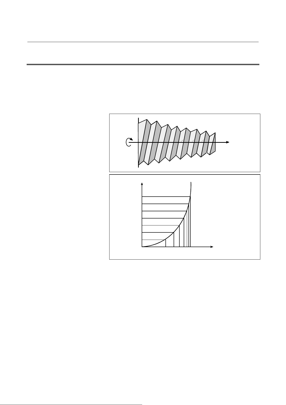
B-63782EN/01 NC FUNCTIONS 3.INTERPOLATION FUNCTION
A
A
X
3.12 EXPONENTIAL INTERPOLATION (G02.3,G03.3)
Exponential interpolation exponentially changes the rotation of a
workpiece with respect to movement on the rotary axis. Furthermore,
exponential interpolation performs linear interpolation with respect to
another axis. This enables tapered groove machining with a constant
helix angle (constant helix taper machining). This function is best
suited for grooving and grinding tools such as end mills.β
Z
β
β
3
β
2
1
3
∆X
Helix angle β3= β2= β
X (Linear axis)
∆A
Fig.3.12 Exponential interpolation
1
(Rotary axis)
- 53 -
Page 72

3.INTERPOLATION FUNCTION NC FUNCTIONS B-63782EN/01
Format
Positive rotation (ϖϖϖϖ=0)
G02.3 X_ Y_ Z_ I_ J_ K_ R_ F_ Q_ ;
Negative rotation (ϖϖϖϖ=1)
G03.3 X_ Y_ Z_ I_ J_ K_ R_ F_ Q_ ;
X_ : Specifies an end point with an absolute or
incremental value.
Y_ : Specifies an end point with an absolute or
incremental value.
Z_ : Specifies an end point with an absolute or
incremental value.
I_: Specifies angl I. The specification units conform to
the setting made for the reference axis (parameter
No. 1031).
J_ : Specifies angle J. The specification units conform
to the setting made for the reference axis.
K_ : Specifies the amount to divide the linear axis for
exponential interpolation (span value). Specify a
positive value.
When no value is specified, the setting made in bit
7 (CBK) of parameter No. 7610 is assumed.
If CBK is 0, the value is set in parameter No. 7685.
If CBK is 1, the value specified in K is used.
R_ : Specifies constant R for exponential interpolation.
F_ : Specifies the initial feedrate.
Specified in the same way as an ordinary F code.
Specify a composite feedrate including a feedrate
on the rotary axis.
Q_: Specifies the feedrate at the end point.
The same unit used for F is used. The CNC
internally performs interpolation between the initial
feedrate (F) and final feedrate (Q), depending on
the travel distance on the linear axis.
- 54 -
Page 73

B-63782EN/01 NC FUNCTIONS 3.INTERPOLATION FUNCTION
3.13 SPLINE INTERPOLATION (G06.1)
Spline interpolation produces a spline curve connecting specified
points. When this function is used, the tool moves along the smooth
curve connecting the points. The spline interpolation command
eliminates the need to approximate the smooth curve with minute
straight lines or arcs. A machining program coded with this command
requires less tape than that including the approximation.
Format
The following command sets spline interpolation
mode:
G06.1 ;
In the G06.1 block, a tangent vector at the start
point can be specified.
G06.1 X_ Y_ Z_ ;
X_ : X-axis component of the tangent vector
Y_ : Y-axis component of the tangent vector
Z_ : Z-axis component of the tangent vector
- Sample program
The system is in the spline interpolation mode from N120 to N500 of
the program below:
N110 G00 X_Y_Z_ ; P
1
N120 G06.1 ;
N130 X_Y_Z_ ; P
N140 X_Y_Z_ ; P
N150 X_Y_Z_ ; P
2
3
4
:
N500 X_Y_Z_ ; P
N510 G00 X_Y_Z_ ; P
P
1
n
n+1
P
2
P
3
Fig.3.13 Spline interpolation
P
4
P
P
P
n+1
5
n
- 55 -
Page 74

3.INTERPOLATION FUNCTION NC FUNCTIONS B-63782EN/01
p
p
3.14 SMOOTH INTERPOLATION
To machine a part having sculptured surfaces, such as metal moldings
used in automobiles and airplanes, a part program usually
approximates the sculptured surfaces with minute line segments. As
shown in the following figure, a sculptured curve is normally
approximated using line segments with a tolerance of about 10µm.
Enlarged
10µm
Fig.3.14 (a) Approximation with Line Segments
Either of two types of machining can be selected, depending on the
program command.
1) For those portions where the accuracy of the figure is critical,
such as at corners, machining is performed exactly as specified by
the program command.
2) For those portions having a large radius of curvature where a
smooth figure must be created, points along the machining path
are interpolated with a smooth curve, calculated from the
polygonal lines specified with the program command (smooth
interpolation).
Programming is thus very simple.
Interpolated by smooth curve
N15
N3 N4
Interpolated by smooth curve
N14
N13
N5
N1
Linear inter
N17
N16
N2
olation
: Specified point
N12
N6
N7
N11
N8
Linear inter
N10
N9
olation
N17
N5
N13
N6
N12
N7
N11
N8
N10
N9
N16
N1
N2
Fig.3.14 (b) Smooth Interpolation and Linear Interpolation
N15
N3 N4
N14
Following command enables smooth interpolation ;
G5.1Q2X0Y0Z0 ; : Starting of smooth interpolation mode
: : Smooth interpolation
G5.1Q0 ; : Cancellation of smooth interpolation mode
- 56 -
Page 75
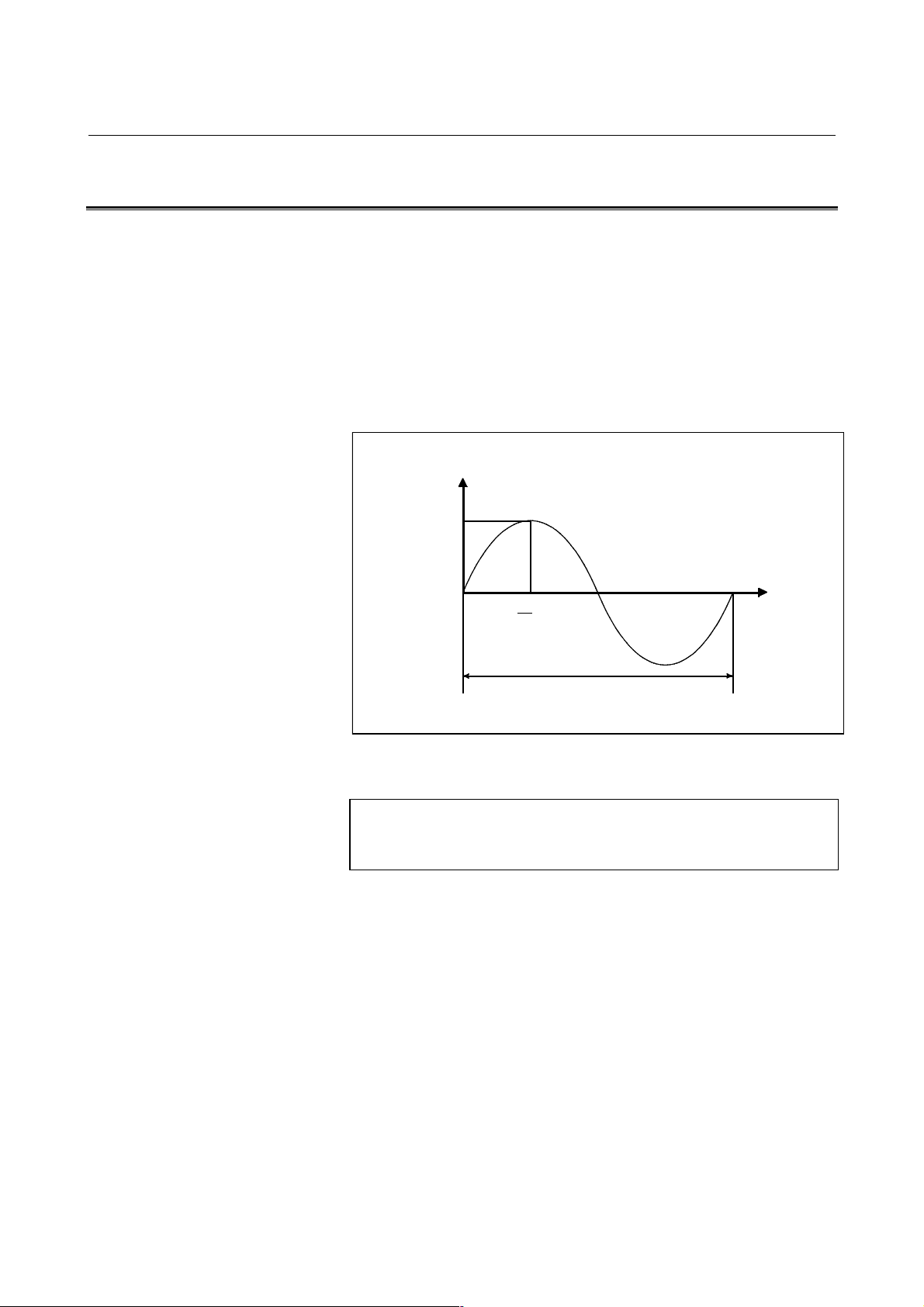
B-63782EN/01 NC FUNCTIONS 3.INTERPOLATION FUNCTION
π
2
π
3.15 HYPOTHETICAL AXIS INTERPOLATION (G07)
In helical interpolation, when pulses are distributed with one of the
circular interpolation axes set to a hypothetical axis, sine interpolation
is enabled.
When one of the circular interpolation axes is set to a hypothetical axis,
pulse distribution causes the speed of movement along the remaining
axis to change sinusoidally. If the major axis for threading (the axis
along which the machine travels the longest distance) is set to a
hypothetical axis, threading with a fractional lead is enabled. The axis
to be set as the hypothetical axis is specified with G07.
Y
r
Format
0
2
1
Z
Fig.3.15 Sine interpolation
G07 αααα0; Hypothetical axis setting
G07 αααα1; Hypothetical axis cancel
Where, α is any one of the addresses of the controlled axes.
- 57 -
Page 76

3.INTERPOLATION FUNCTION NC FUNCTIONS B-63782EN/01
Z+X+Y
3.16 SPIRAL INTERPOLATION, CONICAL INTERPOLATION
(G02,G03)
Spiral interpolation is enabled by specifying the circular interpolation
command together with a desired number of revolutions or a desired
increment (decrement) for the radius per revolution.
Conical interpolation is enabled by specifying the spiral interpolation
command together with one or two additional axes of movement, as
well as a desired increment (decrement) for the position along the
additional axes per spiral revolution.
- Spiral interpolation
+Y
- Conical interpolation
+X
Fig.3.16 (a) Spiral interpolation
+
Fig.3.16 (b) Conical interpolation
- 58 -
Page 77

B-63782EN/01 NC FUNCTIONS 3.INTERPOLATION FUNCTION
Format
- Spiral interpolation
Xp-Yp plane
G02
G17 X_Y_I_J_Q_L_F_ ;
G03
Zp-Yp plane
G02
G18 Z_X_K_I_Q_L_F_ ;
G03
Yp-Zp plane
G02
G19 Y_Z_J_K_Q_L_F_ ;
G03
X,Y,Z :Coordinates of the end point
L : Number of revolutions (positive value without a
decimal point) (*1)
Q : Radius increment or decrement per spiral revolution
(*1)
I,J,K :Signed distance from the start point to the center
(same as the distance specified for circular
interpolation)
F : Feedrate
(*1) Either the number of revolutions (L) or the radius
increment or decrement (Q) can be omitted. When L is
omitted, the number of revolutions is automatically
calculated from the distance between the current
position and the center, the position of the end point,
and the radius increment or decrement. When Q is
omitted, the radius increment or decrement is
automatically calculated from the distance between the
current position and the center, the position of the end
point, and the number of revolutions. If both L and Q
are specified but their values contradict, Q takes
precedence. Generally, either L or Q should be
specified. The L value must be a positive value without
a decimal point. To specify four revolutions plus 905,
for example, round the number of revolutions up to five
and specify L5.
- 59 -
Page 78

3.INTERPOLATION FUNCTION NC FUNCTIONS B-63782EN/01
- Conical interpolation
Xp-Yp plane
G17 G02/G03 X_Y_I_J_Z_Q_L_F_ ;
Zp-Yp plane
G18 G02/G03 Z_X_K_I_Y_Q_L_F_ ;
Yp-Zp plane
G19 G02/G03 Y_Z_J_K_X_Q_L_F_ ;
X,Y,Z : Coordinates of the end point
L : Number of revolutions (positive value without a decimal point)(*1)
Q : Radius increment or decrement per spiral revolution (*1)
I,J,K :Two of the three values represent a signed vector from the start point to the
center. The remaining value is a height increment or decrement per spiral
revolution in conical interpolation (*1)
When the XpYp plane is selected:
The I and J values represent a signed vector from the start point to the
center. The K value represents a height increment or decrement per
spiral revolution.
When the ZpXp plane is selected:
The K and I values represent a signed vector from the start point to the
center. The J value represents a height increment or decrement per
spiral revolution.
When the YpZp plane is selected:
The J and K values represent a signed vector from the start point to the
center. The I value represents a height increment or decrement per
spiral revolution.
F :Feedrate (*2)
(*1) One of the height increment/decrement (I, J, K), radius increment/decrement
(Q), and the number of revolutions (L) must be specified. The other two items
can be omitted.
Sample command for the Xp-Yp plane
G17 G02/G03 Y_Y_I_J_Z_ K_/Q_/L_ F_ ;
If both L and Q are specified, but their values contradict, Q takes precedence.
If both L and a height increment or decrement are specified, but their values
contradict, the height increment or decrement takes precedence. If both Q and
a height increment or decrement are specified, but their values contradict, Q
takes precedence. The L value must be a positive value without a decimal
point. To specify four revolutions plus 905, for example, round the number of
revolutions up to five and specify L5.
(*2)As the feedrate, whether to specify a feedrate tangent to an arc or a tangential
feedrate, determined also by considering movement along the linear axes,
can be set in bit 2 (HTG) of parameter No. 1401.
- 60 -
Page 79

B-63782EN/01 NC FUNCTIONS 3.INTERPOLATION FUNCTION
3.17 NURBS INTERPOLATION(G06.2)
Many computer-aided design (CAD) systems used to design metal dies
for automobiles utilize non-uniform rational B-spline (NURBS) to
express a sculptured surface or curve for the metal dies.
This function enables NURBS curve expression to be directly specified
to the CNC. This eliminates the need for approximating the NURBS
curve with minute line segments. This offers the following advantages:
1. No error due to approximation of a NURBS curve by small line
segments
2. Short part program
3. No break between blocks when small blocks are executed at high
speed
4. No need for high-speed transfer from the host computer to the
CNC
When this function is used, a computer-aided machining (CAM)
system creates a NURBS curve according to the NURBS expression
output from the CAD system, after compensating for the length of the
tool holder, tool diameter, and other tool elements. The NURBS curve
is programmed in the NC format by using these three defining
parameters: control point, weight and knot.
CAD (designing a metal die)
Generating a metal die surface
(NURBS surface or curve)
CAM (creating an NC part program)
Studying the
machining method, etc.
Tool compensation file
NC part program after tool compensation
(NURBS curve)
NURBS curve (control point, weight, knot)
CNC
Fig.3.17 (a) NC part program for machining a metal die according to a
NURBS curve
Machine tool
The CNC executes NURBS interpolation while smoothly accelerating
or decelerating the movement so that the acceleration on each axis will
not exceed the allowable maximum acceleration of the machine. In this
way, the CNC automatically controls the speed in order to prevent
excessive strain being imposed on the machine.
- 61 -
Page 80

3.INTERPOLATION FUNCTION NC FUNCTIONS B-63782EN/01
Format
G06.2 [P_ ] K_ IP_ [R_ ] [F_ ] ;
K_ IP_ [R_ ] ;
K_ IP_ [R_ ] ;
K_ IP_ [R_ ] ;
…
K_ IP_ [R_ ] ;
K_ ;
…
K_ ;
G01…
…
G06.2 : Start NURBS interpolation mode
P_ : Rank of NURBS curve
IP_ : Control point (Up to the maximum number of
controlled axes can be specified.)
R_ : Weight
K_ : Knot
F_ : Feedrate
NOTE
NOTE
If the axis name extension function uses address K to
specify an axis name, it is impossible to perform
NURBS interpolation. (Alarm PS1002 is issued.)
- 62 -
Page 81

B-63782EN/01 NC FUNCTIONS 3.INTERPOLATION FUNCTION
3.17.1 NURBS Interpolation Additional Functions
The functions below are added to the NURBS interpolation function of
the FANUC Series 15i.
- Parametric feedrate control
The maximum feedrate of each segment is determined by a specified
feedrate and acceleration value. For successive segments, a feedrate at
a segment start point and a feedrate at a segment end point are
determined as described below. Then, the feedrate changes
successively during movement from the start point to the end point.
This function is applicable only to NURBS interpolation when bit 5
(FDI) of parameter No. 8412 is set to 1.
- High-precision knot command
When bit 1 (HIK) of parameter No. 8412 is set to 1, a knot command
consisting of up to 12 integer digits and up to 12 fraction digits can be
specified. This function is applicable only to a knot command (address
K) including a decimal point during NURBS interpolation.
- Simple start command
When bit 0 (EST) of parameter No. 8412 is set to 1, a control point
command can be omitted at the first control point. The knot values of
the first block and the second block are the same, so that the knot
command can be omitted for the first block only.
- Maximum cutting feedrate along each axis
With the conventional specification, the specified feedrate F during
NURBS interpolation is clamped to the minimum value of the
maximum cutting feedrate (parameter No. 1422) of each axis as
indicated by the expression below.
So, when the maximum cutting feedrate of a rotation axis F
the specified feedrate F during NURBS interpolation may be clamped
to F
This function changes the method of clamping the specified feedrate F
as described below.
The specified feedrate F is clamped so that the component of F along
each axis does not exceed the maximum cutting feedrate (parameter No.
1422) of each corresponding axis (Fig. 3.17.1(a)).
of the rotation axis, resulting in an increase in machining time.
max
))(),(),(),(),(Min(
BFAFZFYFXFF ≤
maxmaxmaxmaxmax
is small,
max
- 63 -
Page 82

3.INTERPOLATION FUNCTION NC FUNCTIONS B-63782EN/01
F(1)
- Rollover
- Inverse time feed
1 segment
F
F(t)
F
F(0)
F
Fig. 3.17.1(a)
If a control point is specified in the absolute mode (G90) for a rotation
axis subject to rollover, the relative position shift of the control point
based on a shortcut is calculated after rollover processing for the
control point.
If G93 is specified during NURBS interpolation, the inverse time
command (G93) mode is set. Specify an inverse time (FRN) with F
code. FRN for NURBS interpolation is represented by the following
expression:
Feedrate
FRN =
Distance
Feedrate: mm/min (metric input) or inch/min (inch input)
Distance: mm (metric input) or inch (inch input)
(Travel distance along a NURBS curve. This distance does not
always represent a travel distance if a rotation axis is
involved.)
- 64 -
Page 83
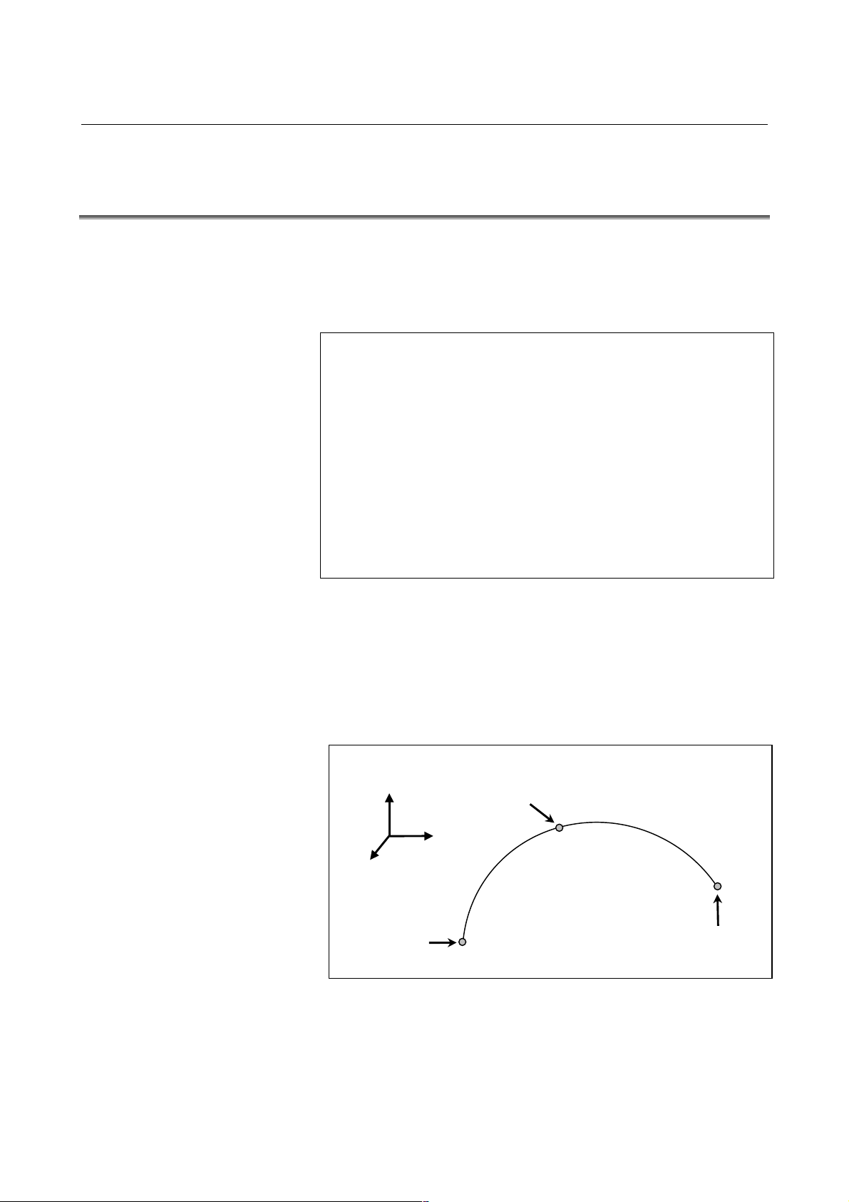
B-63782EN/01 NC FUNCTIONS 3.INTERPOLATION FUNCTION
3.18 3-DIMENSIONAL CIRCULAR INTERPOLATION (G02.4 AND
G03.4)
Specifying an intermediate and end point on an arc enables circular
interpolation in a 3-dimensional space.
Format
The command format is as follows:
G02.4 X
X
X1 YY1 ZZ1
X1 YY1 ZZ1
Or,
G03.4 X
X
X1 YY1 ZZ1
X1 YY1 ZZ1
α,β : Arbitrary axes other than the 3-dimensional circular
interpolation axis (up to two axes)
- Start point, mid-point, and end point
An arc in a 3-dimensional space is uniquely defined with its start point
(current position) and a specified intermediate point and end point, as
shown below. Two command blocks are used to define this arc. The
first command block specifies the tool path between the start point and
intermediate point. The second command block specifies the tool path
between the intermediate point and end point.
X
αααα
αααα
αααα
β
β
; First block (mid-point of the arc)
β β
α1
α1
β1
β1
α1α1
β1β1
β
β
; Second block (end point of the arc)
β β
α1
α1
β1
β1
α1α1
β1β1
αααα
β
β
; First block (mid-point of the arc)
β β
α1
α1
β1
β1
α1α1
β1β1
β
β
; Second block (end point of the arc)
β β
α1
α1
β1
β1
α1α1
β1β1
Mid-point
(X1,Y1,Z1)
Z
Start point
- 65 -
Y
End point
(X2,Y2,Z2)
Fig. 3.18 Start, Mid, and End Points
Page 84

4.THREAD CUTTING NC FUNCTIONS B-63782EN/01
4 THREAD CUTTING
- 66 -
Page 85
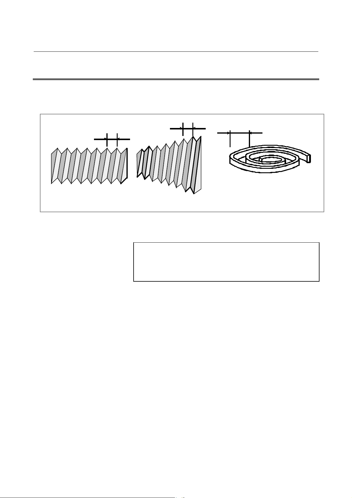
B-63782EN/01 NC FUNCTIONS 4.THREAD CUTTING
(S
)
4.1 THREAD CUTTING (G33)
The G33 command produces a straight or tapered thread having a
constant lead.
L : Lead
Straig ht thread
Format
Explanation
L
L
Taper thread
Fig.4.1 (a) Thread
L
Front thread
troke thread
G33 IP_ F_ Q_ ;
F_ : Larger component of lead
Q_ : Angle by which the threading start angle is shifted
(0 to 360deg.)
In general, thread cutting is repeated along the same tool path in rough
cutting through finish cutting for a screw. Since thread cutting starts
when the position coder mounted on the spindle outputs a 1-turn signal,
threading is started at a fixed point and the tool path on the workpiece is
unchanged for repeated thread cutting. Note that the spindle speed
must remain constant from rough cutting through finish cutting. If not,
incorrect thread lead will occur.
- 67 -
Page 86
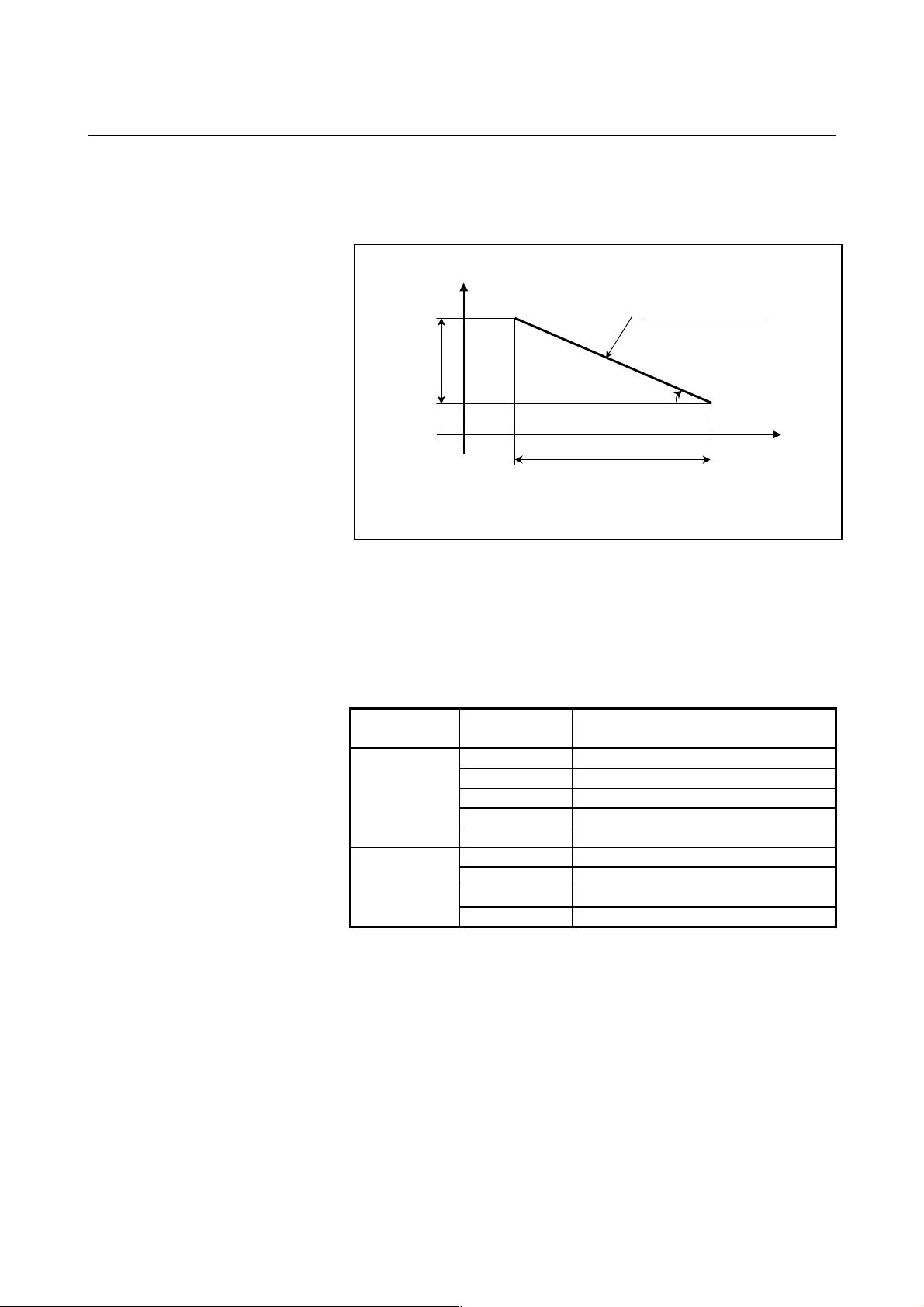
4.THREAD CUTTING NC FUNCTIONS B-63782EN/01
X
g
When a tapered thread is produced, the lead must be specified with the
magnitude of a larger component. A lathe which holds and rotates a
workpiece can produce a tapered thread on the workpiece.
Lead of tapered thread
LX
α
Z
LZ
When angle α is less than or equal to 45°, specify LZ.
When an
In general, the lag of the servo system, etc. will produce somewhat
incorrect leads at the starting and ending points of a thread cut. To
compensate for this, a thread cutting length somewhat longer than
required should be specified.
Table 4.1 (a) lists the ranges for specifying the thread lead.
le α is greater than or equal to 45°, specify LX.
Fig.4.1 (b) Lead Position
Table4.1 (a) Ranges of lead sizes that can be specified
mm input
Inch input
Least command
increment
0.01 mm 0.001 to 5000.0000 mm/rev
0.001 mm 0.00001 to 500.00000 mm/rev
0.0001 mm 0.000001 to 50.000000 mm/rev
0.00001 mm 0.0000001 to 5.0000000 mm/rev
0.000001 mm 0.00000001 to 0.50000000 mm/rev
0.001 inch 0.00001 to 500.00000 inch/rev
0.0001 inch 0.000001 to 50.00000 inch/rev
0,00001 inch 0.0000001 to 5.0000000 inch/rev
0.000001 inch 0.00000001 to 0.50000000 inch/rev
Command value range of the lead
- 68 -
Page 87

B-63782EN/01 NC FUNCTIONS 4.THREAD CUTTING
4.2 INCH THREADING (G33)
When a number of thread ridges per inch is specified with address E, an
inch thread can be produced with high precision.
Format
G33 IP_ E_ Q_;
E_ : Number of thread ridges per inch
Q_ : Number of thread ridges per inch at threading start angle
- 69 -
Page 88

4.THREAD CUTTING NC FUNCTIONS B-63782EN/01
4.3 CONTINUOUS THREADING (G33)
Continuous threading can be executed when multiple blocks containing
the threading command are specified in succession.
Explanation
At the interface between blocks, the system keeps synchronous control
of the spindle as much as possible. The lead or profile of a thread can
be changed in the middle of threading.
- Threading start angle
G33
G33
Fig.4.3 Continuous threading
Repeating the threading operations along an identical path with a
different depth of cut enables the thread to be produced correctly.
The threading start angle can be shifted only in the block in which the
first threading operation is started.
G33
- 70 -
Page 89

B-63782EN/01 NC FUNCTIONS 5.FEED FUNCTION
5 FEED FUNCTION
- 71 -
Page 90

5.FEED FUNCTION NC FUNCTIONS B-63782EN/01
5.1 RAPID TRAVERSE
Positioning of each axis is done in rapid motion by the positioning
command (G00).
There is no need to program rapid traverse rate, because the rates are set
in the parameter (per axis)
Least command increment Rapid traverse rate range
0.001mm,deg 30 to 240000mm/min,deg/min
0.0001mm,deg 30 to 99999mm/min,deg/min
0.0001inch 3.0 to 24000.0inch/min
0.00001inch 3.0 to 9999.9inch/min
(When input unit is same machine unit,)
NOTE
The above feed rates are limits according to the NC's
interpolation capacity when the high-resolution
detection interface is equipped. When the whole
system is considered, there are also limits according
to the servo system.
For details, refer to Appendix A.
- 72 -
Page 91
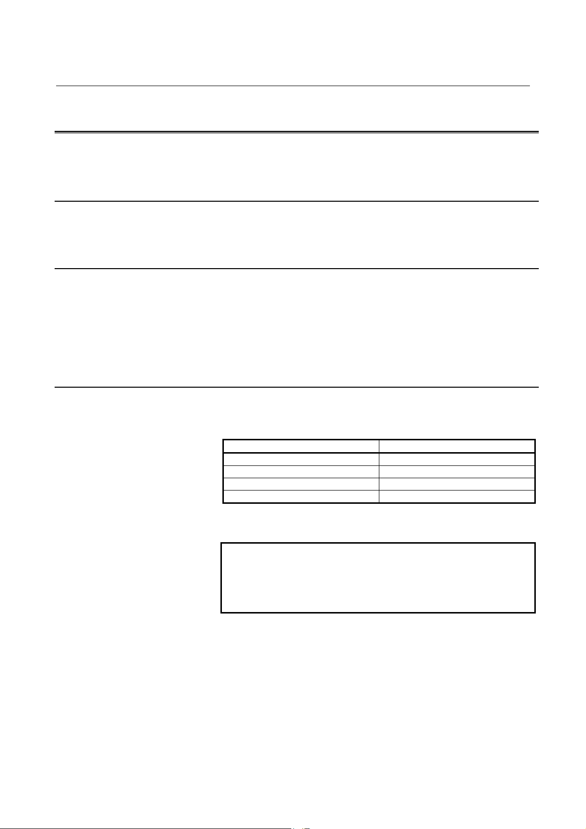
B-63782EN/01 NC FUNCTIONS 5.FEED FUNCTION
5.2 CUTTING FEED
After an F code, specify the feedrate value for linear interpolation (G01),
circular interpolation (G02 and G03), or the like.
5.2.1 Tangential Speed Constant Control
Cutting feed is controlled so that the tangential feedrate is always set at a
specified feedrate.
5.2.2 Cutting Feedrate Clamp
A common upper limit can be set on the cutting feedrate along each axis
with parameter No. 1422. If an actual cutting feedrate (with an override
applied) exceeds a specified upper limit, it is clamped to the upper limit.
When the cutting feedrate along an axis exceeds the maximum feedrate
for the axis as a result of interpolation, the cutting feedrate is clamped to
the maximum feedrate.
5.2.3 Feed Per Minute (G94)
With the per minute feed mode G94, tool feed rate per minute is directly
commanded by numerical value after F.
Least command increment Cutting feed rate range
0.001mm,deg 0.0001 to 240000mm/min,deg/min
0.0001mm,deg 0.0001 to 99999mm/min,deg/min
0.0001inch 0.00001 to 240000inch/min
0.00001inch 0.00001 to 9999.9inch/min
(If the input unit differs from the machine unit, the feedrate range differs
from the above table.)
NOTE
The above feed rates are limits according to the NC's
interpolation capacity. When the whole system is
considered, there are also limits according to the
servo system. For details, see Appendix A.
- 73 -
Page 92

5.FEED FUNCTION NC FUNCTIONS B-63782EN/01
5.2.4 Feed Per Revolution (G95)
With the per revolution feed mode G95, tool feed rate per revolution of
the spindle is directly commanded by numeral after F. A position coder
must be mounted on the spindle.
However, the feed-per-revolution command can be enabled by setting the
corresponding parameter accordingly, even when the position coder is
not installed (feed per revolution without position coder).
Least command increment Cutting feed rate range
0.001mm,deg 0.01 to 500mm/rev,deg/rev
0.0001mm,deg 0.01 to 500mm/rev,deg/rev
0.0001inch 0.0001 to 50inch/rev
0.00001inch 0.0001 to 50inch/rev
(If the input unit differs from the machine unit, the feedrate range differs
from the above table.)
NOTE
The above feed rates are limits according to the NC's
interpolation capacity. When the whole system is
considered there are also limits according to the
servo system.
5.2.5 Inverse Time Feed (G93)
Inverse time feed mode is commanded by G93, and inverse time by F
code. Inverse time is commanded with the following value in a 1/min
unit.
- In linear interpolation
F: Speed/distance
- In circular interpolation
F: Speed/radius
When F0 is commanded, alarm occurs.
5.2.6 One-digit F Code Feed
When a 1-digit number from 1 to 9 is commanded after the F, the preset
speed corresponding the 1-digit number commanded is set as feed rate.
When F0 is commanded, rapid traverse is set.
Set the F1-digit feed rate change input signal on from the machine side,
and rotate the manual pulse generator. Feed rate of the currently selected
speed can be changed.
Feed rate set or changed will be memorized even after power is turned
off.
- 74 -
Page 93

B-63782EN/01 NC FUNCTIONS 5.FEED FUNCTION
X
X
5.2.7 Setting Input of Cutting Feedrate
With some machines, the cutting feedrate need not be changed frequently
during machining. For such machines, a cutting feedrate (a non-zero
value) can be set in parameter. With this function, the cutting feedrate (F
code) need not be specified in the NC command data.
5.2.8 Feedrate Specification on a Virtual Circle for a Rotary Axis
The method of feedrate specification on a machine with a rotation axis is
improved.
[Conventional method]
Specified
Y
C
feedrate
(deg/min)
N2
N1
Sample program:
N1G91G01X10.F100.
N2C10.F50
The feedrate of the rotation
axis is specified using the
speed of the rotation axis.
[Method of feedrate specification on a virtual circle for a rotation axis]
C
Specified
feedrate
(mm/min)
N2
N1
Sample program:
N1G91G01X10.F100.
N2C10.
The travel feedrate on the
virtual circle of a radius
specified by a parameter is
the specified feedrate.
By setting a virtual radius of 0,
the rotation axis can be
excluded from feedrate
calculation.
Y
Virtual
circle
radius
NOTE
By using this function, the travel feedrate on a virtual
circle becomes the specified feedrate. In general,
however, the feedrate at a cutting point does not
become a specified feedrate.
- 75 -
Page 94

5.FEED FUNCTION NC FUNCTIONS B-63782EN/01
5.3 OVERRIDE
5.3.1 Feedrate Override
The per minute feed (G94) and per rotation feed (G95) can be overrided
by:
0 to 254% (per every 1%).
In inverse time, feed rate converted to per minute feed is overridden.
Feed rate override cannot be performed to F1-digit feed.
Feed rate also cannot be performed to functions as thread cutting and
tapping in which override is inhibited.
5.3.2 Second Feed Rate Override
Cutting feed rate can be overrided by:
0 to 254% (per every 1%)
or
0 to 655.34% (per every 0.01%) (for parameter setting)
A second override can be performed on feed rats once overrided.
No override can be performed on functions as thread cutting and tapping
in which second feedrate override is inhibited.
This function is used for controlling feed rate in adaptive control, etc.
5.3.3 Rapid Traverse Override
The rapid traverse rate can be overridden as follows:
F0, F1%, 50%, 100%
F0 : Feedrate to be set for each axis (parameter)
F1 : Percentage (parameter)
or, 0% to 100% (in steps of 1%) by setting parameter
5.3.4 Override Cancel
When an override cancel switch is provided on the machine operator's
panel, the feedrate override (together with the second feedrate override)
can be clamped to 100%.
5.3.5 Jog Override
The manual continuous feedrate and incremental feed rate can be
overridden by:
0% to 655.34% (in steps of 0.01%)
- 76 -
Page 95

B-63782EN/01 NC FUNCTIONS 5.FEED FUNCTION
5.4 ACCELERATION/DECELERATION CONTROL
5.4.1 Automatic Acceleration/Deceleration Control After
Interpolation
Acceleration and deceleration is performed when starting and ending
movement, resulting in smooth start and stop. Automatic
acceleration/deceleration is also performed when feedrate changes, so
change in speed is also smoothly done. It is not necessary to take
acceleration/deceleration into consideration when programming.
The following automatic acceleration/deceleration after interpolation
can be performed for rapid traverse, cutting feed (including dry run), and
jog feed:
- Linear acceleration/deceleration
- Bell-shaped acceleration/deceleration
- Exponential acceleration/deceleration
For rapid traverse, acceleration/deceleration of the constant acceleration
type can be set, thus allowing efficient acceleration/deceleration at the
acceleration set for each axis. However, when linear interpolation-type
positioning is performed, the path may not match the specified line,
because acceleration/deceleration is performed for each axis.
- Linear acceleration/deceleration
With linear acceleration/deceleration, the time required for
acceleration/deceleration is the shortest, provided that the acceleration is
the same. Note, however, that if the acceleration is large (the time
constant is low), the stress and strain imposed on the machine system
may be considerable.
- Bell-shaped acceleration/deceleration
This type of acceleration/deceleration is named from its
acceleration/deceleration plots shaped like a bell. Even when a large
acceleration is set, smooth acceleration/deceleration in the start and end
of a change in speed can reduce a shock to the machine system.
- Exponential acceleration/deceleration
With exponential acceleration/deceleration, the acceleration/
deceleration delay is large. On large machines, however, the overshoot
can be reduced.
- 77 -
Page 96

5.FEED FUNCTION NC FUNCTIONS B-63782EN/01
r
Linear acceleration/deceleration
Speed
F
0
T
Bell-shaped acceleration/deceleration
Speed
F
0
T
Exponential function acceleration/deceleration
Speed
F
F : Command speed
T : Acceleration/
T
F : Command speed
T : Acceleration/
T
F : Command speed
T : Acceleration/
deceleration time
constant
: Low feed rate afte
F
L
deceleration
deceleration time
constant
Time
deceleration time
constant
Time
F
0
TT
L
Time
- 78 -
Page 97
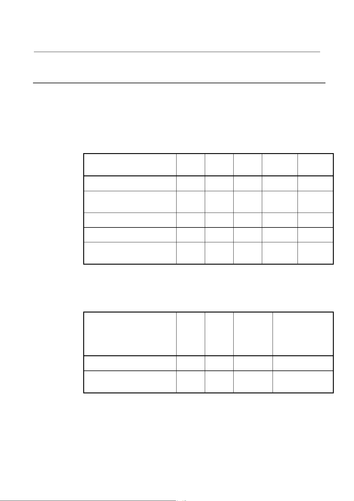
B-63782EN/01 NC FUNCTIONS 5.FEED FUNCTION
5.4.2 Acceleration/Deceleration before Interpolation of Linear-Type
Rapid Traverse
Conventionally, only acceleration/deceleration after interpolation could
be applied to rapid traverse.
This function enables acceleration/deceleration before interpolation to
be applied to linear-type rapid traverse.
- Acceleration/deceleration after interpolation to rapid traverse
Table 5.4.2 (a) Acceleration/Deceleration after Interpolation to Rapid Traverse
Acceleration/deceleration type REX
Linear-type acceleration/deceleration
at constant acceleration
Bell-shaped
acceleration/deceleration at constant
acceleration
Exponential acceleration/deceleration
in constant time
Linear-type acceleration/deceleration
in constant time
Bell-shaped
acceleration/deceleration in constant
time
As listed above, five types of acceleration/deceleration after
interpolation could conventionally be used for rapid traverse.
NEX
1600#0
0 0 0 No.1620 No.1621
0 0 1 No.1620
1 0 - No.1628 No.1629
1 1 0 No.1628 None
1 1 1 No.1628 None
1600#7
RTB
1601#5
Time
constant
parameter
No.1636
FL feedrate
parameter
None
- Acceleration/deceleration before interpolation to rapid traverse
Table 5.4.2 (b) Acceleration/Deceleration before Interpolation to Rapid Traverse
Acceleration/deceleration type FRP
Linear-type acceleration/deceleration
before interpolation
Bell-shaped
acceleration/deceleration before
interpolation
As shown above, acceleration/deceleration before interpolation is also
enabled for rapid traverse by parameter setting.
1603#5
1 1 No.1671 No.1672 = 0
1 1 No.1671 No.1672 = other than 0
LRP
1400#4
Acceleration
parameter
Parameter of
acceleration
change period in
bell-shaped
acceleration/
deceleration
- 79 -
Page 98
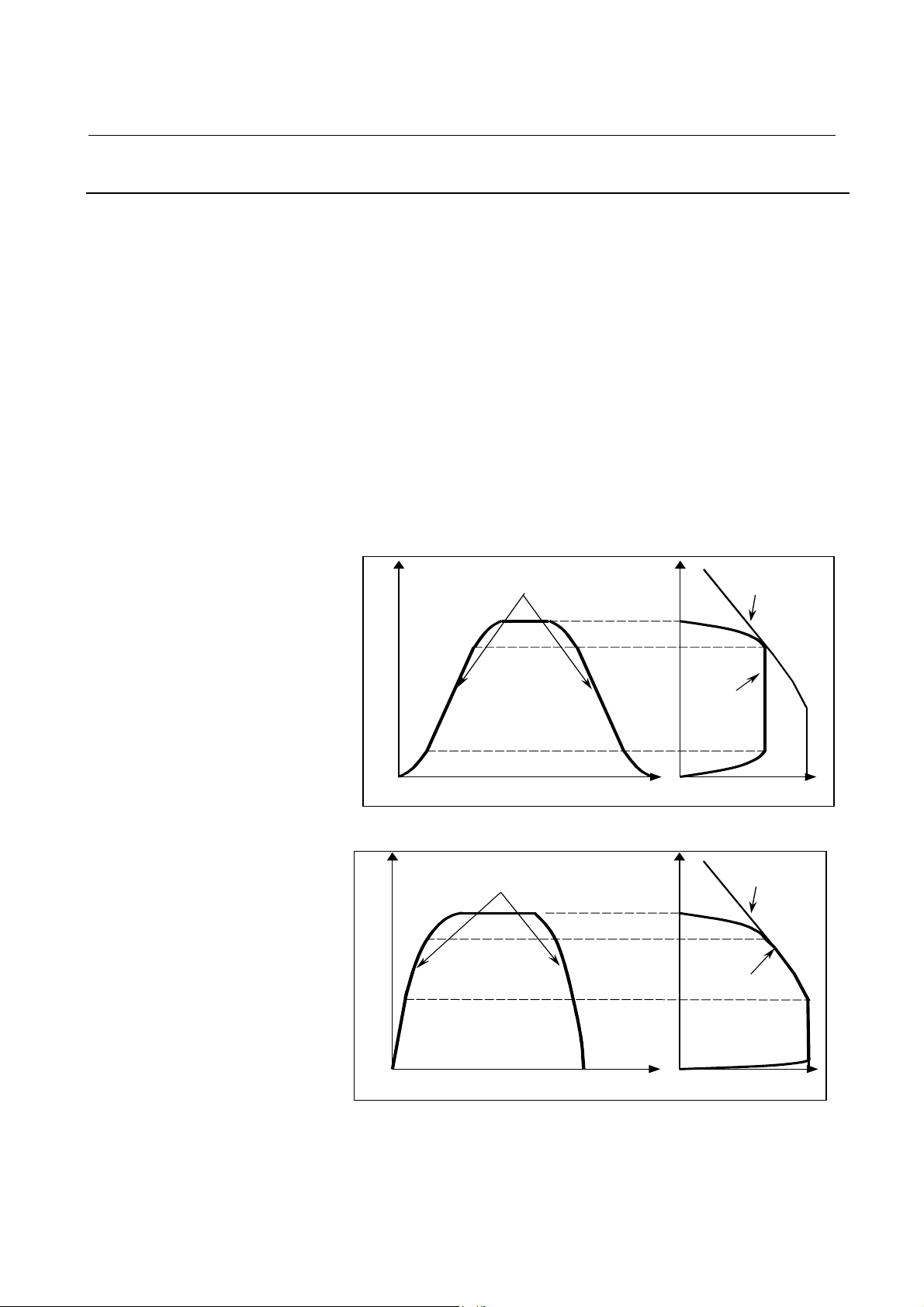
5.FEED FUNCTION NC FUNCTIONS B-63782EN/01
5.4.3 Optimum Torque Acceleration/Deceleration
This function enables acceleration/deceleration in accordance with the
torque characteristics of the motor and the characteristics of the
machines due to its friction and gravity. Usually, because of the friction
and gravity of the machine, the torque characteristics of the motor, and
other factors, the acceleration/deceleration performance that is attainable
(referred to as the limited acceleration/deceleration curve) is not
symmetrical with respect to the line separating the low- and high-speed
portions. This function enables acceleration/deceleration in such a way
that in positioning, the actual acceleration curve follows the limited
acceleration curve as closely as possible. This makes the most of the
capability of the motor, reducing positioning time.
By setting limited acceleration curve data for each axis using the
appropriate parameter, this function performs linear type positioning
with acceleration/deceleration on the basis of limited acceleration curve
data in the state in which look-ahead acceleration/deceleration is
effective.
Speed
Move com m and after
acceleration/deceleration
: Pa ttern s ym m etrica l with re sp ect to the
line separating acceleration and
deceleration portions
Speed
A ctua l acc elera tion
Time Acceleration
Lim ited a cc ele ra tion
curve
curve
Fig. 5.4.3 (a) Conventional bell-shaped acceleration/declaration
Speed
Mo ve comm and after
acceleration/deceleration
: Acceleration/deceleration curve
following limited acceleration curve
Speed
Limited
acce le ration curve
Actual acceleration
curve
Tim e
Acceleration
Fig. 5.4.3 (b) Acceleration/deceleration with this function where the actual
acceleration curve follows the limited acceleration curve
- 80 -
Page 99
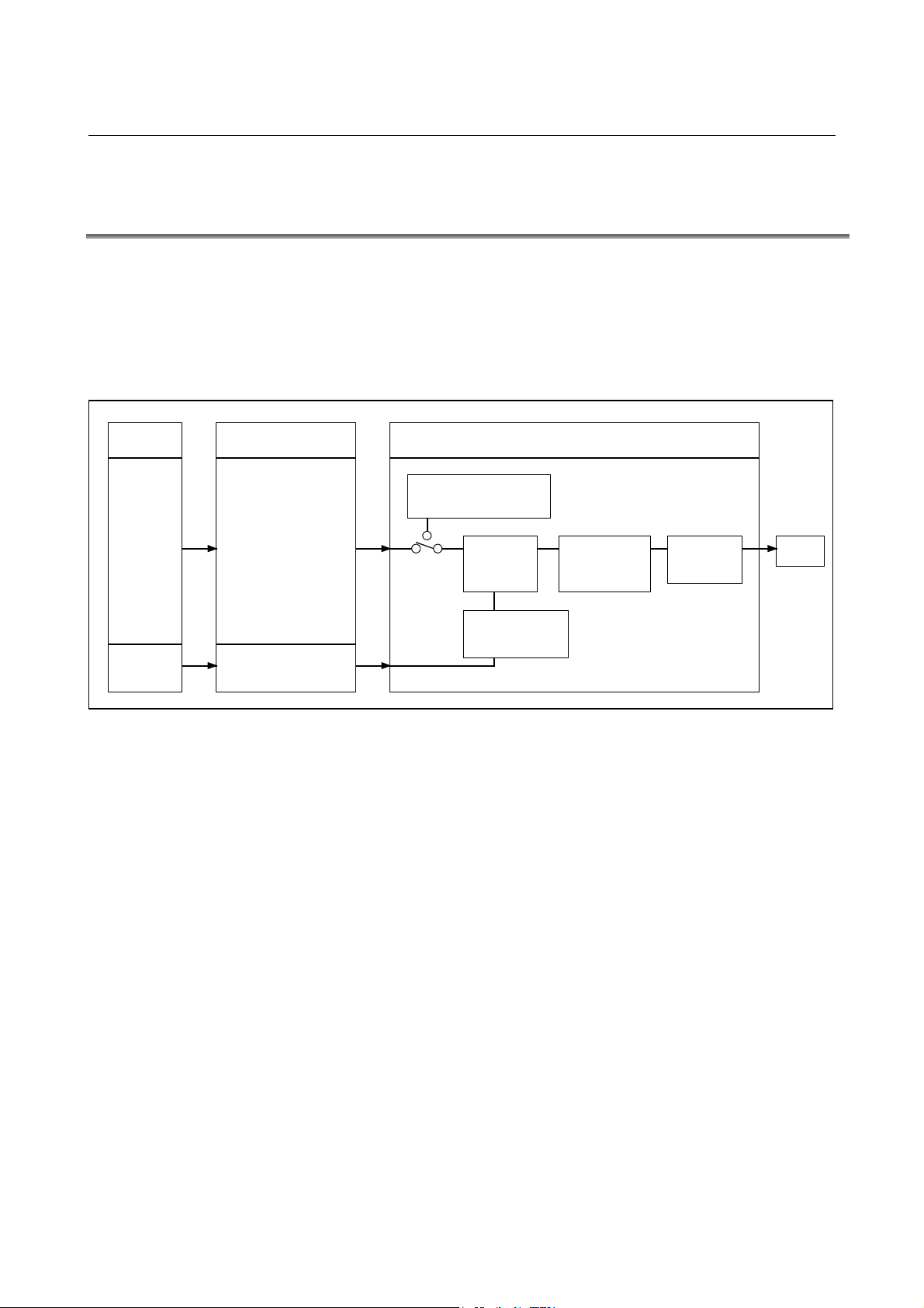
B-63782EN/01 NC FUNCTIONS 5.FEED FUNCTION
5.5 PMC AXIS CONTROL CONSTANT FEEDRATE COMMAND
ACCELERATION/DECELERATION FUNCTION
When a constant feedrate is specified with the PMC axis control function,
linear acceleration/deceleration can be applied to the specified feedrate
at the start and end of movement.
As a result, smooth start and stop is possible. Moreover, when the
feedrate changes during movement, acceleration/deceleration is applied
automatically, so that the feedrate changes smoothly.
PMC
Controlled
axis
Constant
feedrate
command
Stop
command
Controlled-axis block
Data signal
Constant feedrate
command
Rotation speed data
Axis control data
Stop command
Skip signal
Fig. 5.5 When a Constant-Feedrate Command is Specified
Axis management (rotation
axis)
Constant
feedrate
control
Signal monitor When this signal is set to 1,
CNCBMI
Acceleration/dece
leration control
constant-speed rotation stops.
Servo control
Motor
- 81 -
Page 100
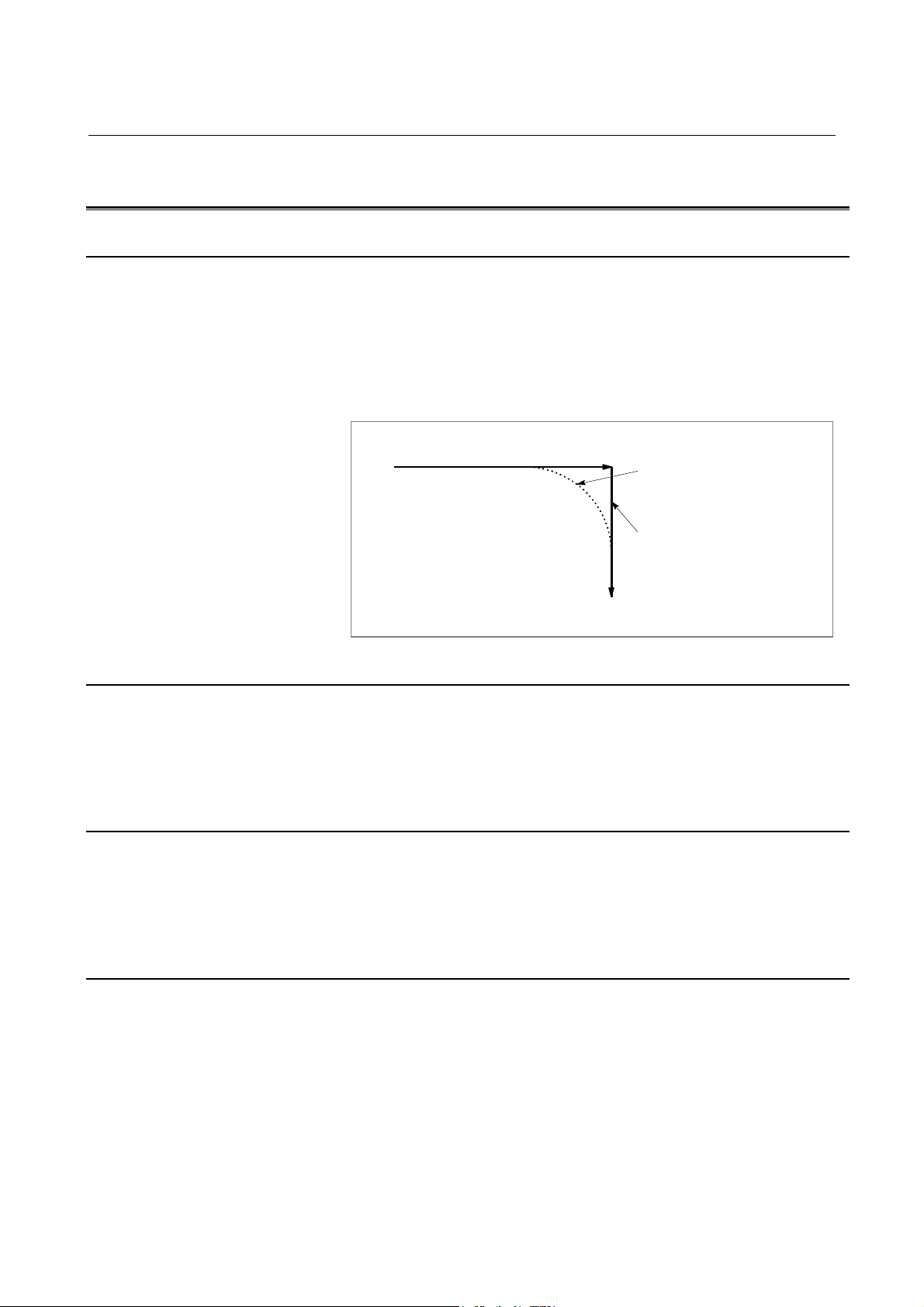
5.FEED FUNCTION NC FUNCTIONS B-63782EN/01
f
5.6 SPEED CNTROL COMMAND AT THE CORNER OF BLOCK
5.6.1 Exact Stop (G09)
Move command in blocks commanded with G09 decelerates at the end
point, and in-position check is performed. G09 command is not
necessary for deceleration at the end point for positioning (G00) and inposition check is also done automatically.
This function is used when sharp edges are required for workpiece
corners in cutting feed.
Exact stop off
Exact stop on (The in-position
check is performed at the end o
a block.)
5.6.2 Exact Stop Mode (G61)
When G61 is commanded, deceleration of cutting feed command at the
end point and in-position check is performed per block thereafter. This
G61 is valid till G64 (cutting mode), G62 (automatic corner override), or
G63 (tapping mode) is commanded.
5.6.3 Cutting Mode (G64)
When G64 is commanded, deceleration at the end point of each block
thereafter is not performed and cutting goes on to the next block. This
command is valid till G61 (exact stop mode), G62 (automatic corner
override), or G63 (tapping mode) is commanded.
5.6.4 Tapping Mode (G63)
When G63 is commanded, feed rate override is ignored (always
regarded as 100%), and feed hold also becomes invalid. Cutting feed
does not decelerate at the end of block to transfer to the next block. And
in-tapping signal is issued during tapping operation. This G63 is valid
till G61 (exact stop mode), G62 (automatic corner override), or G64
(cutting mode) is commanded.
- 82 -
 Loading...