

Page 1

CONNECTION MANUAL (HARDWARE)
B-63783EN/01
Page 2

• No part of this manual may be reproduced in any form.
• All specifications and designs are subject to change without notice.
The products in this manual are controlled based on Japan’s “Foreign Exchange and
Foreign Trade Law”. The export from Japan may be subject to an export license by the
government of Japan.
Further, re-export to another country may be subject to the license of the government of
the country from where the product is re-exported. Furthermore, the product may also be
controlled by re-export regulations of the United States government.
Should you wish to export or re-export these products, please contact FANUC for advice.
In this manual we have tried as much as possible to describe all the various matters.
However, we cannot describe all the matters which must not be done, or which cannot be
done, because there are so many possibilities.
Therefore, matters which are not especially described as possible in this manual should be
regarded as ”impossible”.
This manual contains the program names or device names of other companies, some of
which are registered trademarks of respective owners. However, these names are not
followed by ® or ™ in the main body.
Page 3

B–63783EN/01
DEFINITION OF WARNING, CAUTION, AND NOTE
DEFINITION OF WARNING, CAUTION, AND NOTE
This manual includes safety precautions for protecting the user and preventing damage to the
machine. Precautions are classified into W arning and Caution according to their bearing on safety.
Also, supplementary information is described as a Note. Read the Warning, Caution, and Note
thoroughly before attempting to use the machine.
WARNING
Applied when there is a danger of the user being injured or when there is a danger of both the user
being injured and the equipment being damaged if the approved procedure is not observed.
CAUTION
Applied when there is a danger of the equipment being damaged, if the approved procedure is not
observed.
NOTE
The Note is used to indicate supplementary information other than Warning and Caution.
` Read this manual carefully, and store it in a safe place.
s–1
Page 4

Page 5

B–63783EN/01
Table of Contents
DEFINITION OF WARNING, CAUTION, AND NOTE s–1. . . . . . . . . . . . . . . . . . . . . . . . . .
1. GENERAL 1. . . . . . . . . . . . . . . . . . . . . . . . . . . . . . . . . . . . . . . . . . . . . . . . . . . . . . . . . . . .
2. CONFIGURATION 4. . . . . . . . . . . . . . . . . . . . . . . . . . . . . . . . . . . . . . . . . . . . . . . . . . . . .
3. INSTALLATION 6. . . . . . . . . . . . . . . . . . . . . . . . . . . . . . . . . . . . . . . . . . . . . . . . . . . . . . . .
3.1 ENVIRONMENTAL REQUIREMENTS OUTSIDE THE CABINET 7. . . . . . . . . . . . . . . . . . . . . . .
3.1.1 Environmental Conditions Around the Cabinet 7. . . . . . . . . . . . . . . . . . . . . . . . . . . . . . . . . . . . . . . . . .
3.1.2 Installation Conditions for the CNC and Servo Unit Inside the Cabinet 8. . . . . . . . . . . . . . . . . . . . . . . .
3.2 POWER REQUIREMENTS 9. . . . . . . . . . . . . . . . . . . . . . . . . . . . . . . . . . . . . . . . . . . . . . . . . . . . . . . .
3.3 DESIGN AND INSTALLATION CONDITIONS OF THE MACHINE TOOL
MAGNETIC CABINET 10. . . . . . . . . . . . . . . . . . . . . . . . . . . . . . . . . . . . . . . . . . . . . . . . . . . . . . . . . . .
3.4 PROTECTION OF PARTS INSIDE A CABINET OR A PENDANT BOX FROM DUST 12. . . . . . .
3.5 THERMAL DESIGN OF THE CABINET 13. . . . . . . . . . . . . . . . . . . . . . . . . . . . . . . . . . . . . . . . . . . .
3.5.1 T emperature Rise within the Cabinet 13. . . . . . . . . . . . . . . . . . . . . . . . . . . . . . . . . . . . . . . . . . . . . . . . . .
3.5.2 Cooling by Heat Exchanger 13. . . . . . . . . . . . . . . . . . . . . . . . . . . . . . . . . . . . . . . . . . . . . . . . . . . . . . . . .
3.5.3 Calorific Value of Each Unit 14. . . . . . . . . . . . . . . . . . . . . . . . . . . . . . . . . . . . . . . . . . . . . . . . . . . . . . . . .
3.6 ACTION AGAINST NOISE 16. . . . . . . . . . . . . . . . . . . . . . . . . . . . . . . . . . . . . . . . . . . . . . . . . . . . . . .
3.6.1 Separating Signal Lines 16. . . . . . . . . . . . . . . . . . . . . . . . . . . . . . . . . . . . . . . . . . . . . . . . . . . . . . . . . . . .
3.6.2 Grounding 17. . . . . . . . . . . . . . . . . . . . . . . . . . . . . . . . . . . . . . . . . . . . . . . . . . . . . . . . . . . . . . . . . . . . . .
3.6.3 Grounding Units 18. . . . . . . . . . . . . . . . . . . . . . . . . . . . . . . . . . . . . . . . . . . . . . . . . . . . . . . . . . . . . . . . . .
3.6.4 Noise Suppresser 22. . . . . . . . . . . . . . . . . . . . . . . . . . . . . . . . . . . . . . . . . . . . . . . . . . . . . . . . . . . . . . . . .
3.6.5 Cable Clamp and Shield Processing 23. . . . . . . . . . . . . . . . . . . . . . . . . . . . . . . . . . . . . . . . . . . . . . . . . . .
3.7 MEASURES AGAINST SURGES DUE TO LIGHTNING 26. . . . . . . . . . . . . . . . . . . . . . . . . . . . . . .
3.7.1 Installation Procedure of Sur ge Protector 26. . . . . . . . . . . . . . . . . . . . . . . . . . . . . . . . . . . . . . . . . . . . . . .
3.7.2 Notes 27. . . . . . . . . . . . . . . . . . . . . . . . . . . . . . . . . . . . . . . . . . . . . . . . . . . . . . . . . . . . . . . . . . . . . . . . . .
3.7.3 Examples of Surge Protectors 27. . . . . . . . . . . . . . . . . . . . . . . . . . . . . . . . . . . . . . . . . . . . . . . . . . . . . . . .
3.8 CONTROL UNIT 28. . . . . . . . . . . . . . . . . . . . . . . . . . . . . . . . . . . . . . . . . . . . . . . . . . . . . . . . . . . . . . . .
3.8.1 Configuration and Installation of the Control Unit 28. . . . . . . . . . . . . . . . . . . . . . . . . . . . . . . . . . . . . . . .
3.8.2 Replacing the Battery for Memory Backup 30. . . . . . . . . . . . . . . . . . . . . . . . . . . . . . . . . . . . . . . . . . . . . .
3.9 CABLE–LEAD–IN DIAGRAM 34. . . . . . . . . . . . . . . . . . . . . . . . . . . . . . . . . . . . . . . . . . . . . . . . . . . . .
3.9.1 Control Unit Periphery Connector Layouts 34. . . . . . . . . . . . . . . . . . . . . . . . . . . . . . . . . . . . . . . . . . . . .
3.9.2 LCD Unit Periphery Connector Layout 43. . . . . . . . . . . . . . . . . . . . . . . . . . . . . . . . . . . . . . . . . . . . . . . .
4. TOTAL CONNECTION 47. . . . . . . . . . . . . . . . . . . . . . . . . . . . . . . . . . . . . . . . . . . . . . . . . .
4.1 CONNECTIONS BETWEEN CONTROL UNITS 48. . . . . . . . . . . . . . . . . . . . . . . . . . . . . . . . . . . . . .
4.2 CONNECTIONS BETWEEN SERVO CARD 51. . . . . . . . . . . . . . . . . . . . . . . . . . . . . . . . . . . . . . . . .
4.3 CONNECTIONS BETWEEN LCD UNIT 53. . . . . . . . . . . . . . . . . . . . . . . . . . . . . . . . . . . . . . . . . . . . .
5. POWER SUPPLY UNIT CONNECTION 54. . . . . . . . . . . . . . . . . . . . . . . . . . . . . . . . . . .
5.1 POWER SOURCE UNIT PANEL CONNECTOR LAYOUT 55. . . . . . . . . . . . . . . . . . . . . . . . . . . . . .
5.2 POWER SUPPLY CONNECTION 56. . . . . . . . . . . . . . . . . . . . . . . . . . . . . . . . . . . . . . . . . . . . . . . . . .
5.2.1 Connection when an Input Unit is Used 56. . . . . . . . . . . . . . . . . . . . . . . . . . . . . . . . . . . . . . . . . . . . . . . .
5.2.2 Power ON/OFF Sequence 59. . . . . . . . . . . . . . . . . . . . . . . . . . . . . . . . . . . . . . . . . . . . . . . . . . . . . . . . . .
6. CONNECTION OF I/O UNITS TO MACHINE INTERFACE 61. . . . . . . . . . . . . . . . . .
6.1 GENERAL 62. . . . . . . . . . . . . . . . . . . . . . . . . . . . . . . . . . . . . . . . . . . . . . . . . . . . . . . . . . . . . . . . . . . . .
6.2 CONNECTION OF THE FANUC I/O LINK 64. . . . . . . . . . . . . . . . . . . . . . . . . . . . . . . . . . . . . . . . . . .
c–1
Page 6

Table of Contents
6.2.1 Connection of FANUC I/O Link by Electric Cable 65. . . . . . . . . . . . . . . . . . . . . . . . . . . . . . . . . . . . . . . .
6.2.2 Connection of FANUC I/O Link Optical Fiber Cable 66. . . . . . . . . . . . . . . . . . . . . . . . . . . . . . . . . . . . . .
B–63783EN/01
6.3 CONNECTION OF CONNECTOR PANEL I/O MODULE 71. . . . . . . . . . . . . . . . . . . . . . . . . . . . . . .
6.3.1 Configuration 71. . . . . . . . . . . . . . . . . . . . . . . . . . . . . . . . . . . . . . . . . . . . . . . . . . . . . . . . . . . . . . . . . . . .
6.3.2 Connection Diagram 72. . . . . . . . . . . . . . . . . . . . . . . . . . . . . . . . . . . . . . . . . . . . . . . . . . . . . . . . . . . . . . .
6.3.3 Module Specification 73. . . . . . . . . . . . . . . . . . . . . . . . . . . . . . . . . . . . . . . . . . . . . . . . . . . . . . . . . . . . . .
6.3.4 DI/DO Connector Pin Assignment 75. . . . . . . . . . . . . . . . . . . . . . . . . . . . . . . . . . . . . . . . . . . . . . . . . . . .
6.3.5 DI (Input Signal) Connection 77. . . . . . . . . . . . . . . . . . . . . . . . . . . . . . . . . . . . . . . . . . . . . . . . . . . . . . . .
6.3.6 DO (Output Signal) Connection 79. . . . . . . . . . . . . . . . . . . . . . . . . . . . . . . . . . . . . . . . . . . . . . . . . . . . . .
6.3.7 DI/DO Signal Ratings 80. . . . . . . . . . . . . . . . . . . . . . . . . . . . . . . . . . . . . . . . . . . . . . . . . . . . . . . . . . . . . .
6.3.8 2A–Output Connector Pin Assignment Diagram 82. . . . . . . . . . . . . . . . . . . . . . . . . . . . . . . . . . . . . . . . .
6.3.9 2A DO (Output Signal) Connection 83. . . . . . . . . . . . . . . . . . . . . . . . . . . . . . . . . . . . . . . . . . . . . . . . . . .
6.3.10 2A–Output DO Signal Ratings 84. . . . . . . . . . . . . . . . . . . . . . . . . . . . . . . . . . . . . . . . . . . . . . . . . . . . . . .
6.3.11 Analog Input Connector Pin Assignment Diagram 85. . . . . . . . . . . . . . . . . . . . . . . . . . . . . . . . . . . . . . . .
6.3.12 Analog Input Signal Connection 86. . . . . . . . . . . . . . . . . . . . . . . . . . . . . . . . . . . . . . . . . . . . . . . . . . . . .
6.3.13 Analog Input Signal Ratings 87. . . . . . . . . . . . . . . . . . . . . . . . . . . . . . . . . . . . . . . . . . . . . . . . . . . . . . . . .
6.3.14 Analog Input Specification 88. . . . . . . . . . . . . . . . . . . . . . . . . . . . . . . . . . . . . . . . . . . . . . . . . . . . . . . . . .
6.3.15 Manual Pulse Generator Connection 91. . . . . . . . . . . . . . . . . . . . . . . . . . . . . . . . . . . . . . . . . . . . . . . . . . .
6.3.16 Cable Length for Manual Pulse Generator 92. . . . . . . . . . . . . . . . . . . . . . . . . . . . . . . . . . . . . . . . . . . . . .
6.3.17 Connection of Basic and Extension Modules 93. . . . . . . . . . . . . . . . . . . . . . . . . . . . . . . . . . . . . . . . . . . .
6.3.18 Module Installation 95. . . . . . . . . . . . . . . . . . . . . . . . . . . . . . . . . . . . . . . . . . . . . . . . . . . . . . . . . . . . . . . .
6.3.19 Other Notes 100. . . . . . . . . . . . . . . . . . . . . . . . . . . . . . . . . . . . . . . . . . . . . . . . . . . . . . . . . . . . . . . . . . . . .
6.3.20 Distribution I/O Setting 103. . . . . . . . . . . . . . . . . . . . . . . . . . . . . . . . . . . . . . . . . . . . . . . . . . . . . . . . . . . .
6.4 CONNECTION OF OPERATOR’S PANEL I/O MODULE (FOR MATRIX INPUT) 106. . . . . . . . . . .
6.4.1 Overall Connection Diagram 106. . . . . . . . . . . . . . . . . . . . . . . . . . . . . . . . . . . . . . . . . . . . . . . . . . . . . . . .
6.4.2 Power Connection 107. . . . . . . . . . . . . . . . . . . . . . . . . . . . . . . . . . . . . . . . . . . . . . . . . . . . . . . . . . . . . . . .
6.4.3 DI/DO Connector Pin Arrangement 108. . . . . . . . . . . . . . . . . . . . . . . . . . . . . . . . . . . . . . . . . . . . . . . . . . .
6.4.4 DI (General–purpose Input Signal) Connection 109. . . . . . . . . . . . . . . . . . . . . . . . . . . . . . . . . . . . . . . . . .
6.4.5 DI (Matrix Input Signal) Connection 111. . . . . . . . . . . . . . . . . . . . . . . . . . . . . . . . . . . . . . . . . . . . . . . . . .
6.4.6 DO (Output Signal) Connection 112. . . . . . . . . . . . . . . . . . . . . . . . . . . . . . . . . . . . . . . . . . . . . . . . . . . . . .
6.4.7 Manual Pulse Generator Connection 115. . . . . . . . . . . . . . . . . . . . . . . . . . . . . . . . . . . . . . . . . . . . . . . . . . .
6.4.8 External View 116. . . . . . . . . . . . . . . . . . . . . . . . . . . . . . . . . . . . . . . . . . . . . . . . . . . . . . . . . . . . . . . . . . . .
6.4.9 Specifications 117. . . . . . . . . . . . . . . . . . . . . . . . . . . . . . . . . . . . . . . . . . . . . . . . . . . . . . . . . . . . . . . . . . . .
6.4.10 Other Notes 119. . . . . . . . . . . . . . . . . . . . . . . . . . . . . . . . . . . . . . . . . . . . . . . . . . . . . . . . . . . . . . . . . . . . .
6.5 CONNECTION OF OPERATOR’S PANEL I/O MODULE (NOT FOR MATRIX INPUT) 123. . . . . .
6.5.1 Overall Connection Diagram 123. . . . . . . . . . . . . . . . . . . . . . . . . . . . . . . . . . . . . . . . . . . . . . . . . . . . . . . .
6.5.2 Power Connection 124. . . . . . . . . . . . . . . . . . . . . . . . . . . . . . . . . . . . . . . . . . . . . . . . . . . . . . . . . . . . . . . .
6.5.3 DI/DO Connector Pin Arrangement 125. . . . . . . . . . . . . . . . . . . . . . . . . . . . . . . . . . . . . . . . . . . . . . . . . . .
6.5.4 DI (General–Purpose Input Signal) Connection 126. . . . . . . . . . . . . . . . . . . . . . . . . . . . . . . . . . . . . . . . . .
6.5.5 DO (Output Signal) Connection 130. . . . . . . . . . . . . . . . . . . . . . . . . . . . . . . . . . . . . . . . . . . . . . . . . . . . . .
6.5.6 Manual Pulse Generator Connection 132. . . . . . . . . . . . . . . . . . . . . . . . . . . . . . . . . . . . . . . . . . . . . . . . . . .
6.5.7 External View 132. . . . . . . . . . . . . . . . . . . . . . . . . . . . . . . . . . . . . . . . . . . . . . . . . . . . . . . . . . . . . . . . . . . .
6.5.8 Specifications 133. . . . . . . . . . . . . . . . . . . . . . . . . . . . . . . . . . . . . . . . . . . . . . . . . . . . . . . . . . . . . . . . . . . .
6.5.9 Other Notes 135. . . . . . . . . . . . . . . . . . . . . . . . . . . . . . . . . . . . . . . . . . . . . . . . . . . . . . . . . . . . . . . . . . . . .
6.6 CONNECTION OF THE FANUC I/O UNIT–MODEL A 139. . . . . . . . . . . . . . . . . . . . . . . . . . . . . . . . .
6.6.1 Structure of FANUC I/O Unit–MODEL A 139. . . . . . . . . . . . . . . . . . . . . . . . . . . . . . . . . . . . . . . . . . . . . .
6.6.2 Outer Dimensions 139. . . . . . . . . . . . . . . . . . . . . . . . . . . . . . . . . . . . . . . . . . . . . . . . . . . . . . . . . . . . . . . . .
6.6.3 Mounting and Dismounting Modules 140. . . . . . . . . . . . . . . . . . . . . . . . . . . . . . . . . . . . . . . . . . . . . . . . . .
6.6.4 Connection Diagram 141. . . . . . . . . . . . . . . . . . . . . . . . . . . . . . . . . . . . . . . . . . . . . . . . . . . . . . . . . . . . . . .
6.6.5 Connecting Input Power Source 142. . . . . . . . . . . . . . . . . . . . . . . . . . . . . . . . . . . . . . . . . . . . . . . . . . . . . .
6.6.6 Grounding 143. . . . . . . . . . . . . . . . . . . . . . . . . . . . . . . . . . . . . . . . . . . . . . . . . . . . . . . . . . . . . . . . . . . . . .
6.6.7 Connecting Signal Cables 144. . . . . . . . . . . . . . . . . . . . . . . . . . . . . . . . . . . . . . . . . . . . . . . . . . . . . . . . . . .
6.6.8 Connecting with I/O Modules 147. . . . . . . . . . . . . . . . . . . . . . . . . . . . . . . . . . . . . . . . . . . . . . . . . . . . . . . .
6.6.9 Digital Input/Output Module 148. . . . . . . . . . . . . . . . . . . . . . . . . . . . . . . . . . . . . . . . . . . . . . . . . . . . . . . .
6.6.10 Correspondence between I/O Signals and Addresses in a Module 150. . . . . . . . . . . . . . . . . . . . . . . . . . . .
6.6.11 Number of Points for I/O Unit–MODEL A 151. . . . . . . . . . . . . . . . . . . . . . . . . . . . . . . . . . . . . . . . . . . . .
c–2
Page 7

B–63783EN/01
6.7 CONNECTION OF MACHINE OPERATOR’S PANEL INTERFACE UNIT 152. . . . . . . . . . . . . . . . .
6.8 CONNECTING THE CONNECTION UNIT 174. . . . . . . . . . . . . . . . . . . . . . . . . . . . . . . . . . . . . . . . . .
6.9 CONNECTION OF OPERATOR’S PANEL CONNECTION UNIT 201. . . . . . . . . . . . . . . . . . . . . . . . .
6.10 CONNECTION OF SOURCE OUTPUT OPERATOR’S PANEL CONNECTION UNIT 215. . . . . . . .
6.11 ADDRESS–FIXED SIGNALS 233. . . . . . . . . . . . . . . . . . . . . . . . . . . . . . . . . . . . . . . . . . . . . . . . . . . . . .
6.12 CONNECTION TO THE MACHINE OPERATOR’S PANEL 234. . . . . . . . . . . . . . . . . . . . . . . . . . . . .
Table of Contents
6.7.1 Function Overview 152. . . . . . . . . . . . . . . . . . . . . . . . . . . . . . . . . . . . . . . . . . . . . . . . . . . . . . . . . . . . . . . .
6.7.2 System Configuration 154. . . . . . . . . . . . . . . . . . . . . . . . . . . . . . . . . . . . . . . . . . . . . . . . . . . . . . . . . . . . . .
6.7.3 Signal Assignment 155. . . . . . . . . . . . . . . . . . . . . . . . . . . . . . . . . . . . . . . . . . . . . . . . . . . . . . . . . . . . . . . .
6.7.4 Interface 157. . . . . . . . . . . . . . . . . . . . . . . . . . . . . . . . . . . . . . . . . . . . . . . . . . . . . . . . . . . . . . . . . . . . . . . .
6.7.5 PMC Addresses 167. . . . . . . . . . . . . . . . . . . . . . . . . . . . . . . . . . . . . . . . . . . . . . . . . . . . . . . . . . . . . . . . . .
6.7.6 Major Connection Precautions 168. . . . . . . . . . . . . . . . . . . . . . . . . . . . . . . . . . . . . . . . . . . . . . . . . . . . . . .
6.7.7 State of the LEDs on the Machine Operator’s Panel Interface Unit 168. . . . . . . . . . . . . . . . . . . . . . . . . . . .
6.7.8 Connector (on the Cable Side) Specifications 169. . . . . . . . . . . . . . . . . . . . . . . . . . . . . . . . . . . . . . . . . . . .
6.7.9 Machine Operator’s Panel Interface Unit Dimension Diagram (Including Connector Locations) 170. . . . .
6.7.10 Machine Operator’s Panel Interface Unit Mounting Dimension Diagram 171. . . . . . . . . . . . . . . . . . . . . . .
6.7.11 Fuse Mounting Position 173. . . . . . . . . . . . . . . . . . . . . . . . . . . . . . . . . . . . . . . . . . . . . . . . . . . . . . . . . . . .
6.8.1 Connecting Connection Unit 1 and Connection Unit 2 176. . . . . . . . . . . . . . . . . . . . . . . . . . . . . . . . . . . . .
6.8.2 Input Signal Regulations for the Connection Unit 178. . . . . . . . . . . . . . . . . . . . . . . . . . . . . . . . . . . . . . . .
6.8.3 Connector Pin Assignment for the Connection Unit 180. . . . . . . . . . . . . . . . . . . . . . . . . . . . . . . . . . . . . . .
6.8.4 Details of the Connection between the Connection Unit and the Machine 182. . . . . . . . . . . . . . . . . . . . . .
6.8.5 External V iew of the Connection Unit 200. . . . . . . . . . . . . . . . . . . . . . . . . . . . . . . . . . . . . . . . . . . . . . . . .
6.9.1 Input Signal Regulations for the Operator’s Panel Connection Unit 202. . . . . . . . . . . . . . . . . . . . . . . . . . .
6.9.2 Output Signal Regulations for the Operator’s Panel Connection Unit 203. . . . . . . . . . . . . . . . . . . . . . . . . .
6.9.3 Connector Layout for Sink Output Operator’s Panel Connection Unit 205. . . . . . . . . . . . . . . . . . . . . . . . .
6.9.4 Details of the Connection between the Sink Output Operator’s Panel Connection Unit
and the Machine 207. . . . . . . . . . . . . . . . . . . . . . . . . . . . . . . . . . . . . . . . . . . . . . . . . . . . . . . . . . . . . . . . . .
6.9.5 External V iew of Sink Output Operator’s Panel Connection Unit 214. . . . . . . . . . . . . . . . . . . . . . . . . . . . .
6.10.1 Source Output Operator’s Panel Connection Unit Input Signal Standard 216. . . . . . . . . . . . . . . . . . . . . . .
6.10.2 Output Signal Standard for Source Output Operator’s Panel Connection Unit 218. . . . . . . . . . . . . . . . . . .
6.10.3 ALARM LEDs on Source Output Operator’s Panel Connection Unit 221. . . . . . . . . . . . . . . . . . . . . . . . .
6.10.4 Connector Pin Assignment Addresses of Source Output Operator’s Panel Connection Unit 223. . . . . . . . .
6.10.5 Details of Machine Side Connections of Source Output Operator’s Panel Connection Unit 225. . . . . . . . .
6.10.6 External Dimensions of Source Output Operator’s Panel Connection Unit 232. . . . . . . . . . . . . . . . . . . . . .
6.12.1 Overview 234. . . . . . . . . . . . . . . . . . . . . . . . . . . . . . . . . . . . . . . . . . . . . . . . . . . . . . . . . . . . . . . . . . . . . . .
6.12.2 T otal Connection Diagram 236. . . . . . . . . . . . . . . . . . . . . . . . . . . . . . . . . . . . . . . . . . . . . . . . . . . . . . . . . .
6.12.3 Each Connections 237. . . . . . . . . . . . . . . . . . . . . . . . . . . . . . . . . . . . . . . . . . . . . . . . . . . . . . . . . . . . . . . . .
6.12.3.1 Pin assignment 237. . . . . . . . . . . . . . . . . . . . . . . . . . . . . . . . . . . . . . . . . . . . . . . . . . . . . . . . . . . . .
6.12.3.2 Power supply connection 239. . . . . . . . . . . . . . . . . . . . . . . . . . . . . . . . . . . . . . . . . . . . . . . . . . . . .
6.12.3.3 MDI connection 240. . . . . . . . . . . . . . . . . . . . . . . . . . . . . . . . . . . . . . . . . . . . . . . . . . . . . . . . . . . .
6.12.3.4 I/O Link connection 241. . . . . . . . . . . . . . . . . . . . . . . . . . . . . . . . . . . . . . . . . . . . . . . . . . . . . . . . .
6.12.3.5 Emergency stop signal connection 242. . . . . . . . . . . . . . . . . . . . . . . . . . . . . . . . . . . . . . . . . . . . . .
6.12.3.6 Power ON/OFF control signal connection 242. . . . . . . . . . . . . . . . . . . . . . . . . . . . . . . . . . . . . . . .
6.12.3.7 DI (input signal) connection 243. . . . . . . . . . . . . . . . . . . . . . . . . . . . . . . . . . . . . . . . . . . . . . . . . . .
6.12.3.8 DO (output signal) connection 246. . . . . . . . . . . . . . . . . . . . . . . . . . . . . . . . . . . . . . . . . . . . . . . . .
6.12.3.9 Manual pulse generator connection 246. . . . . . . . . . . . . . . . . . . . . . . . . . . . . . . . . . . . . . . . . . . . .
6.12.3.10Connector (on the cable side) specifications. 250. . . . . . . . . . . . . . . . . . . . . . . . . . . . . . . . . . . . . .
6.12.4 DI/DO Address 251. . . . . . . . . . . . . . . . . . . . . . . . . . . . . . . . . . . . . . . . . . . . . . . . . . . . . . . . . . . . . . . . . . .
6.12.4.1 Keyboard of main panel 251. . . . . . . . . . . . . . . . . . . . . . . . . . . . . . . . . . . . . . . . . . . . . . . . . . . . . .
6.12.4.2 Override signals 252. . . . . . . . . . . . . . . . . . . . . . . . . . . . . . . . . . . . . . . . . . . . . . . . . . . . . . . . . . . .
6.12.5 DI/DO Mapping 253. . . . . . . . . . . . . . . . . . . . . . . . . . . . . . . . . . . . . . . . . . . . . . . . . . . . . . . . . . . . . . . . . .
6.12.6 Specifications 254. . . . . . . . . . . . . . . . . . . . . . . . . . . . . . . . . . . . . . . . . . . . . . . . . . . . . . . . . . . . . . . . . . . .
6.12.6.1 Environmental requirement 254. . . . . . . . . . . . . . . . . . . . . . . . . . . . . . . . . . . . . . . . . . . . . . . . . . .
c–3
Page 8

Table of Contents
6.12.6.2 Main panel A/B/A1/B1 specification 255. . . . . . . . . . . . . . . . . . . . . . . . . . . . . . . . . . . . . . . . . . . .
6.12.6.3 Sub panel A/B/B1/C/C1 specification 255. . . . . . . . . . . . . . . . . . . . . . . . . . . . . . . . . . . . . . . . . . .
6.12.6.4 Power supply specification 255. . . . . . . . . . . . . . . . . . . . . . . . . . . . . . . . . . . . . . . . . . . . . . . . . . . .
6.12.6.5 General–purpose DI signal definition 255. . . . . . . . . . . . . . . . . . . . . . . . . . . . . . . . . . . . . . . . . . . .
6.12.6.6 General–purpose DO signal definition 256. . . . . . . . . . . . . . . . . . . . . . . . . . . . . . . . . . . . . . . . . . .
6.12.7 Key Symbol Indication on Machine Operator’s Panel 256. . . . . . . . . . . . . . . . . . . . . . . . . . . . . . . . . . . . .
6.12.7.1 Meaning of key symbols 256. . . . . . . . . . . . . . . . . . . . . . . . . . . . . . . . . . . . . . . . . . . . . . . . . . . . .
6.12.7.2 Detachable key top 258. . . . . . . . . . . . . . . . . . . . . . . . . . . . . . . . . . . . . . . . . . . . . . . . . . . . . . . . . .
6.12.8 Others 259. . . . . . . . . . . . . . . . . . . . . . . . . . . . . . . . . . . . . . . . . . . . . . . . . . . . . . . . . . . . . . . . . . . . . . . . . .
6.12.9 Connector Locations 262. . . . . . . . . . . . . . . . . . . . . . . . . . . . . . . . . . . . . . . . . . . . . . . . . . . . . . . . . . . . . . .
6.12.9.1 Connector locations of main panel A/A1 262. . . . . . . . . . . . . . . . . . . . . . . . . . . . . . . . . . . . . . . . .
6.12.9.2 Connector locations of main panel B/B1 263. . . . . . . . . . . . . . . . . . . . . . . . . . . . . . . . . . . . . . . . .
B–63783EN/01
7. CONNECTION TO CNC PERIPHERALS 264. . . . . . . . . . . . . . . . . . . . . . . . . . . . . . . . . .
7.1 LCD UNIT (DISPLAYUNIT FOR CNC EXCLUSIVE USE) INTERFACE 265. . . . . . . . . . . . . . . . . .
7.1.1 Connection of 1LCD Unit 265. . . . . . . . . . . . . . . . . . . . . . . . . . . . . . . . . . . . . . . . . . . . . . . . . . . . . . . . . .
7.1.1.1 Connection of LCD unit (for 1LCD connection) 266. . . . . . . . . . . . . . . . . . . . . . . . . . . . . . . . . . .
7.1.2 Connection of MDI Unit (with CNC–Only Display Used) 267. . . . . . . . . . . . . . . . . . . . . . . . . . . . . . . . . .
7.1.3 MDI Unit Switch Connection (when LCD Units for T wo–LCD Connection are Used) 269. . . . . . . . . . . .
7.1.4 MDI Unit Connection (with No CNC–Only Display Used) 270. . . . . . . . . . . . . . . . . . . . . . . . . . . . . . . . .
7.1.5 Mounting the PCMCIA Blind Cover on an LCD Unit for T wo–LCD Connection 271. . . . . . . . . . . . . . . .
7.2 I/O UNIT INTERFACE 272. . . . . . . . . . . . . . . . . . . . . . . . . . . . . . . . . . . . . . . . . . . . . . . . . . . . . . . . . . .
7.2.1 RS–232C Serial Port (JD5A, JD5B, JD5C) 272. . . . . . . . . . . . . . . . . . . . . . . . . . . . . . . . . . . . . . . . . . . . .
7.2.2 RS–232C Serial Port (JD36A) 273. . . . . . . . . . . . . . . . . . . . . . . . . . . . . . . . . . . . . . . . . . . . . . . . . . . . . . .
7.2.3 RS422 Serial Port (JD6A, JD6B) 275. . . . . . . . . . . . . . . . . . . . . . . . . . . . . . . . . . . . . . . . . . . . . . . . . . . . .
7.2.4 Connection with F ANUC Handy File 277. . . . . . . . . . . . . . . . . . . . . . . . . . . . . . . . . . . . . . . . . . . . . . . . . .
7.3 MANUAL PULSE GENERATOR INTERFACE 278. . . . . . . . . . . . . . . . . . . . . . . . . . . . . . . . . . . . . . . .
7.4 HIGH–SPEED SKIP (HDI) SIGNAL INTERFACE 280. . . . . . . . . . . . . . . . . . . . . . . . . . . . . . . . . . . . .
7.5 SPINDLE INTERFACE 282. . . . . . . . . . . . . . . . . . . . . . . . . . . . . . . . . . . . . . . . . . . . . . . . . . . . . . . . . . .
7.5.1 α Spindle Interface 283. . . . . . . . . . . . . . . . . . . . . . . . . . . . . . . . . . . . . . . . . . . . . . . . . . . . . . . . . . . . . . . .
7.5.2 Analog Spindle Interface 284. . . . . . . . . . . . . . . . . . . . . . . . . . . . . . . . . . . . . . . . . . . . . . . . . . . . . . . . . . .
7.5.3 Position Coder Interface 285. . . . . . . . . . . . . . . . . . . . . . . . . . . . . . . . . . . . . . . . . . . . . . . . . . . . . . . . . . . .
7.5.4 Connection of 1 to 4 Serial Spindles 287. . . . . . . . . . . . . . . . . . . . . . . . . . . . . . . . . . . . . . . . . . . . . . . . . . .
7.6 SERVO INTERFACE (FSSB) 294. . . . . . . . . . . . . . . . . . . . . . . . . . . . . . . . . . . . . . . . . . . . . . . . . . . . . .
7.6.1 Connection Example When High–Speed HR V Current Control is not Used 294. . . . . . . . . . . . . . . . . . . .
7.6.2 Connection Example when High–Speed HRV Current Control is Used 296. . . . . . . . . . . . . . . . . . . . . . . .
7.6.3 Requirements for the FSSB Line 297. . . . . . . . . . . . . . . . . . . . . . . . . . . . . . . . . . . . . . . . . . . . . . . . . . . . .
7.6.4 Separate Detector Interface Unit 299. . . . . . . . . . . . . . . . . . . . . . . . . . . . . . . . . . . . . . . . . . . . . . . . . . . . . .
7.6.4.1 Separate detector interface unit 299. . . . . . . . . . . . . . . . . . . . . . . . . . . . . . . . . . . . . . . . . . . . . . . . .
7.6.4.2 Power source connection 299. . . . . . . . . . . . . . . . . . . . . . . . . . . . . . . . . . . . . . . . . . . . . . . . . . . . .
7.6.4.3 Battery connection for separate absolute detector 300. . . . . . . . . . . . . . . . . . . . . . . . . . . . . . . . . . .
7.6.4.4 Linear scale interface (parallel interface) 301. . . . . . . . . . . . . . . . . . . . . . . . . . . . . . . . . . . . . . . . . .
7.6.4.5 Linear scale interface (serial interface) 302. . . . . . . . . . . . . . . . . . . . . . . . . . . . . . . . . . . . . . . . . . .
7.6.4.6 Separate pulse coder interface 303. . . . . . . . . . . . . . . . . . . . . . . . . . . . . . . . . . . . . . . . . . . . . . . . . .
7.6.4.7 Input signal rules 305. . . . . . . . . . . . . . . . . . . . . . . . . . . . . . . . . . . . . . . . . . . . . . . . . . . . . . . . . . .
7.6.4.8 Connector layout 306. . . . . . . . . . . . . . . . . . . . . . . . . . . . . . . . . . . . . . . . . . . . . . . . . . . . . . . . . . .
7.6.4.9 Cautions for mounting separate detector interface unit 307. . . . . . . . . . . . . . . . . . . . . . . . . . . . . . .
7.7 GENERAL–PURPOSE VOLTAGE INPUT INTERFACE 311. . . . . . . . . . . . . . . . . . . . . . . . . . . . . . . .
7.8 REMOTE BUFFER INTERFACE 312. . . . . . . . . . . . . . . . . . . . . . . . . . . . . . . . . . . . . . . . . . . . . . . . . . .
7.8.1 Serial Communication Board A1 (RS–232–C) 312. . . . . . . . . . . . . . . . . . . . . . . . . . . . . . . . . . . . . . . . . . .
c–4
Page 9

B–63783EN/01
7.8.2 Serial Communication Board A2 (RS–422) 314. . . . . . . . . . . . . . . . . . . . . . . . . . . . . . . . . . . . . . . . . . . . .
Table of Contents
8. CONNECTION TO OTHER NETWORKS 316. . . . . . . . . . . . . . . . . . . . . . . . . . . . . . . . . .
9. HIGH–SPEED SERIAL BUS (HSSB) 317. . . . . . . . . . . . . . . . . . . . . . . . . . . . . . . . . . . . .
9.1 OVERVIEW 318. . . . . . . . . . . . . . . . . . . . . . . . . . . . . . . . . . . . . . . . . . . . . . . . . . . . . . . . . . . . . . . . . . . .
9.2 CAUTIONS 318. . . . . . . . . . . . . . . . . . . . . . . . . . . . . . . . . . . . . . . . . . . . . . . . . . . . . . . . . . . . . . . . . . . . .
9.3 CONNECTION DIAGRAM 319. . . . . . . . . . . . . . . . . . . . . . . . . . . . . . . . . . . . . . . . . . . . . . . . . . . . . . . .
9.4 SETTING UP THE HSSB INTERFACE BOARD ON THE CNC 320. . . . . . . . . . . . . . . . . . . . . . . . . .
9.5 PERSONAL COMPUTER SPECIFICATION 322. . . . . . . . . . . . . . . . . . . . . . . . . . . . . . . . . . . . . . . . . .
9.5.1 Personal Computer Specifications Required if the ISA Bus Board is Used 322. . . . . . . . . . . . . . . . . . . . . .
9.5.2 Personal Computer Specifications Required if the PCI Bus Board is Used 323. . . . . . . . . . . . . . . . . . . . . .
9.6 INSTALLATION ENVIRONMENT 323. . . . . . . . . . . . . . . . . . . . . . . . . . . . . . . . . . . . . . . . . . . . . . . . .
9.7 PROCEDURE FOR INSTALLING PERSONAL COMPUTER INTERFACE BOARDS 324. . . . . . . .
9.8 HANDLING PRECAUTIONS 326. . . . . . . . . . . . . . . . . . . . . . . . . . . . . . . . . . . . . . . . . . . . . . . . . . . . . .
9.9 RECOMMENDED CABLES 326. . . . . . . . . . . . . . . . . . . . . . . . . . . . . . . . . . . . . . . . . . . . . . . . . . . . . . .
10.CNC DISPLAY UNIT WITH PC FUNCTIONS 327. . . . . . . . . . . . . . . . . . . . . . . . . . . . . .
10.1 OVERVIEW 328. . . . . . . . . . . . . . . . . . . . . . . . . . . . . . . . . . . . . . . . . . . . . . . . . . . . . . . . . . . . . . . . . . . .
10.2 ATTENTION 329. . . . . . . . . . . . . . . . . . . . . . . . . . . . . . . . . . . . . . . . . . . . . . . . . . . . . . . . . . . . . . . . . . . .
10.3 HARDWARE SPECIFICATIONS 330. . . . . . . . . . . . . . . . . . . . . . . . . . . . . . . . . . . . . . . . . . . . . . . . . . .
10.4 TOTAL CONNECTION 332. . . . . . . . . . . . . . . . . . . . . . . . . . . . . . . . . . . . . . . . . . . . . . . . . . . . . . . . . . .
10.4.1 Without Soft–Key & Touch–Panel 332. . . . . . . . . . . . . . . . . . . . . . . . . . . . . . . . . . . . . . . . . . . . . . . . . . . .
10.4.2 With Soft–Key , W ithout Touch–Panel 333. . . . . . . . . . . . . . . . . . . . . . . . . . . . . . . . . . . . . . . . . . . . . . . . .
10.4.3 With Touch–Panel, Without Soft–Key 334. . . . . . . . . . . . . . . . . . . . . . . . . . . . . . . . . . . . . . . . . . . . . . . . .
10.4.4 With Soft–Key and Touch–Panel 335. . . . . . . . . . . . . . . . . . . . . . . . . . . . . . . . . . . . . . . . . . . . . . . . . . . . .
10.5 SPECIFICATION 336. . . . . . . . . . . . . . . . . . . . . . . . . . . . . . . . . . . . . . . . . . . . . . . . . . . . . . . . . . . . . . . .
10.5.1 Environment 336. . . . . . . . . . . . . . . . . . . . . . . . . . . . . . . . . . . . . . . . . . . . . . . . . . . . . . . . . . . . . . . . . . . . .
10.5.2 Power Specification 337. . . . . . . . . . . . . . . . . . . . . . . . . . . . . . . . . . . . . . . . . . . . . . . . . . . . . . . . . . . . . . .
10.5.3 Shutdown Operation 338. . . . . . . . . . . . . . . . . . . . . . . . . . . . . . . . . . . . . . . . . . . . . . . . . . . . . . . . . . . . . . .
10.6 MOUNTING SPACE 339. . . . . . . . . . . . . . . . . . . . . . . . . . . . . . . . . . . . . . . . . . . . . . . . . . . . . . . . . . . . .
10.6.1 Basic Unit 10.4” LCD Type 339. . . . . . . . . . . . . . . . . . . . . . . . . . . . . . . . . . . . . . . . . . . . . . . . . . . . . . . . .
10.6.2 Basic Unit 12.1” LCD T ype 340. . . . . . . . . . . . . . . . . . . . . . . . . . . . . . . . . . . . . . . . . . . . . . . . . . . . . . . . .
10.6.3 Basic Unit 15.0” LCD T ype 340. . . . . . . . . . . . . . . . . . . . . . . . . . . . . . . . . . . . . . . . . . . . . . . . . . . . . . . . .
10.6.4 HDD Unit 341. . . . . . . . . . . . . . . . . . . . . . . . . . . . . . . . . . . . . . . . . . . . . . . . . . . . . . . . . . . . . . . . . . . . . . .
10.7 CONNECTION TO PERIPHERAL 342. . . . . . . . . . . . . . . . . . . . . . . . . . . . . . . . . . . . . . . . . . . . . . . . . .
10.7.1 Connector Location 342. . . . . . . . . . . . . . . . . . . . . . . . . . . . . . . . . . . . . . . . . . . . . . . . . . . . . . . . . . . . . . .
10.7.2 Main Power Input 343. . . . . . . . . . . . . . . . . . . . . . . . . . . . . . . . . . . . . . . . . . . . . . . . . . . . . . . . . . . . . . . . .
10.7.3 Serial Port 1 344. . . . . . . . . . . . . . . . . . . . . . . . . . . . . . . . . . . . . . . . . . . . . . . . . . . . . . . . . . . . . . . . . . . . .
10.7.4 Serial Port 2+USB 346. . . . . . . . . . . . . . . . . . . . . . . . . . . . . . . . . . . . . . . . . . . . . . . . . . . . . . . . . . . . . . . .
10.7.5 Parallel Port 348. . . . . . . . . . . . . . . . . . . . . . . . . . . . . . . . . . . . . . . . . . . . . . . . . . . . . . . . . . . . . . . . . . . . .
10.7.6 High Speed Serial Bus (HSSB) 349. . . . . . . . . . . . . . . . . . . . . . . . . . . . . . . . . . . . . . . . . . . . . . . . . . . . . . .
10.7.7 Mouse 350. . . . . . . . . . . . . . . . . . . . . . . . . . . . . . . . . . . . . . . . . . . . . . . . . . . . . . . . . . . . . . . . . . . . . . . . . .
10.7.8 Full Keyboard 351. . . . . . . . . . . . . . . . . . . . . . . . . . . . . . . . . . . . . . . . . . . . . . . . . . . . . . . . . . . . . . . . . . . .
10.7.9 Hard Disk Drive 352. . . . . . . . . . . . . . . . . . . . . . . . . . . . . . . . . . . . . . . . . . . . . . . . . . . . . . . . . . . . . . . . . .
10.7.10 Floppy Disk Drive (Signal & Power) 353. . . . . . . . . . . . . . . . . . . . . . . . . . . . . . . . . . . . . . . . . . . . . . . . . .
10.7.11 Soft–Key (CNC Display Unit with PC Functions with Soft Key) 355. . . . . . . . . . . . . . . . . . . . . . . . . . . . .
10.7.12 PCMCIA Card 355. . . . . . . . . . . . . . . . . . . . . . . . . . . . . . . . . . . . . . . . . . . . . . . . . . . . . . . . . . . . . . . . . . .
10.8 METHOD OF MOUNTING PCI EXTENSION BOARD 356. . . . . . . . . . . . . . . . . . . . . . . . . . . . . . . . .
10.8.1 Usable Board 356. . . . . . . . . . . . . . . . . . . . . . . . . . . . . . . . . . . . . . . . . . . . . . . . . . . . . . . . . . . . . . . . . . . .
c–5
Page 10

Table of Contents
10.8.2 Method of Mounting PCI Extension Board 356. . . . . . . . . . . . . . . . . . . . . . . . . . . . . . . . . . . . . . . . . . . . .
10.8.3 Method of Mounting PCI Extension Board 357. . . . . . . . . . . . . . . . . . . . . . . . . . . . . . . . . . . . . . . . . . . . .
11.EMERGENCY STOP SIGNAL 358. . . . . . . . . . . . . . . . . . . . . . . . . . . . . . . . . . . . . . . . . . .
APPENDIX
A. UNIT EXTERNAL DIMENSION DIAGRAMS 363. . . . . . . . . . . . . . . . . . . . . . . . . . . . . . .
B. EXTERNAL DIMENSIONS OF CONNECTORS 410. . . . . . . . . . . . . . . . . . . . . . . . . . . .
C. 20–PIN INTERFACE CONNECTORS AND CABLES 435. . . . . . . . . . . . . . . . . . . . . . .
C.1 BOARD–MOUNTED CONNECTORS 436. . . . . . . . . . . . . . . . . . . . . . . . . . . . . . . . . . . . . . . . . . . . . . .
C.2 CABLE CONNECTOR 437. . . . . . . . . . . . . . . . . . . . . . . . . . . . . . . . . . . . . . . . . . . . . . . . . . . . . . . . . . .
C.3 CABLE CONNECTORS 438. . . . . . . . . . . . . . . . . . . . . . . . . . . . . . . . . . . . . . . . . . . . . . . . . . . . . . . . . .
C.4 RECOMMENDED CONNECTORS, APPLICABLE HOUSINGS, AND CABLES 440. . . . . . . . . . . .
C.5 CABLE WIRES 441. . . . . . . . . . . . . . . . . . . . . . . . . . . . . . . . . . . . . . . . . . . . . . . . . . . . . . . . . . . . . . . . .
B–63783EN/01
D. OPTICAL FIBER CABLE 449. . . . . . . . . . . . . . . . . . . . . . . . . . . . . . . . . . . . . . . . . . . . . . .
E. LIQUID CRYSTAL DISPLAY (LCD) 462. . . . . . . . . . . . . . . . . . . . . . . . . . . . . . . . . . . . . . .
F. MEMORY CARD INTERFACE 464. . . . . . . . . . . . . . . . . . . . . . . . . . . . . . . . . . . . . . . . . . .
G. TERMINAL MODULE 469. . . . . . . . . . . . . . . . . . . . . . . . . . . . . . . . . . . . . . . . . . . . . . . . . . .
G.1 OVERVIEW 470. . . . . . . . . . . . . . . . . . . . . . . . . . . . . . . . . . . . . . . . . . . . . . . . . . . . . . . . . . . . . . . . . . . .
G.2 TOTAL CONNECTION 471. . . . . . . . . . . . . . . . . . . . . . . . . . . . . . . . . . . . . . . . . . . . . . . . . . . . . . . . . . .
G.3 CONNECTION OF EACH PART 472. . . . . . . . . . . . . . . . . . . . . . . . . . . . . . . . . . . . . . . . . . . . . . . . . . .
G.3.1 Pin Assignment 472. . . . . . . . . . . . . . . . . . . . . . . . . . . . . . . . . . . . . . . . . . . . . . . . . . . . . . . . . . . . . . . . . .
G.3.1.1 Connector Pin Assignment of Connector Panel I/O Module 472. . . . . . . . . . . . . . . . . . . . . . . . . .
G.3.1.2 Connector–terminal Block Pin Assignment of Terminal Module 473. . . . . . . . . . . . . . . . . . . . . . .
G.3.2 Connection of 24VDC Power Supply and Signals 474. . . . . . . . . . . . . . . . . . . . . . . . . . . . . . . . . . . . . . . .
G.3.2.1 24VDC Power Supply Connection 474. . . . . . . . . . . . . . . . . . . . . . . . . . . . . . . . . . . . . . . . . . . . .
G.3.2.2 DI (Input Signal) Connection 475. . . . . . . . . . . . . . . . . . . . . . . . . . . . . . . . . . . . . . . . . . . . . . . . . .
G.3.2.3 DO (Output Signal) Connector 478. . . . . . . . . . . . . . . . . . . . . . . . . . . . . . . . . . . . . . . . . . . . . . . . .
G.4 MOUNTING TERMINAL MODULE 479. . . . . . . . . . . . . . . . . . . . . . . . . . . . . . . . . . . . . . . . . . . . . . . .
G.5 SPECIFICATIONS 480. . . . . . . . . . . . . . . . . . . . . . . . . . . . . . . . . . . . . . . . . . . . . . . . . . . . . . . . . . . . . . .
G.5.1 Installation Specifications 480. . . . . . . . . . . . . . . . . . . . . . . . . . . . . . . . . . . . . . . . . . . . . . . . . . . . . . . . . . .
G.5.2 Ordering Specifications 480. . . . . . . . . . . . . . . . . . . . . . . . . . . . . . . . . . . . . . . . . . . . . . . . . . . . . . . . . . . .
G.5.3 Module Specifications 480. . . . . . . . . . . . . . . . . . . . . . . . . . . . . . . . . . . . . . . . . . . . . . . . . . . . . . . . . . . . .
G.5.4 Power Voltage 480. . . . . . . . . . . . . . . . . . . . . . . . . . . . . . . . . . . . . . . . . . . . . . . . . . . . . . . . . . . . . . . . . . . .
G.5.5 DI/DO (Input/output Signal Specification) 480. . . . . . . . . . . . . . . . . . . . . . . . . . . . . . . . . . . . . . . . . . . . . .
H. TERMINAL MODULE A 481. . . . . . . . . . . . . . . . . . . . . . . . . . . . . . . . . . . . . . . . . . . . . . . . .
H.1 OVERVIEW 482. . . . . . . . . . . . . . . . . . . . . . . . . . . . . . . . . . . . . . . . . . . . . . . . . . . . . . . . . . . . . . . . . . . .
H.2 TOTAL CONNECTION 483. . . . . . . . . . . . . . . . . . . . . . . . . . . . . . . . . . . . . . . . . . . . . . . . . . . . . . . . . . .
H.3 CONNECTION OF EACH PART 484. . . . . . . . . . . . . . . . . . . . . . . . . . . . . . . . . . . . . . . . . . . . . . . . . . .
c–6
Page 11

B–63783EN/01
H.3.1 Pin Assignment 485. . . . . . . . . . . . . . . . . . . . . . . . . . . . . . . . . . . . . . . . . . . . . . . . . . . . . . . . . . . . . . . . . .
H.3.2 Connection of 24VDC Power Supply and Signals 486. . . . . . . . . . . . . . . . . . . . . . . . . . . . . . . . . . . . . . . .
H.3.2.1 24VDC Power Supply Connection 486. . . . . . . . . . . . . . . . . . . . . . . . . . . . . . . . . . . . . . . . . . . . .
H.3.2.2 DI (Input Signal) Connection 487. . . . . . . . . . . . . . . . . . . . . . . . . . . . . . . . . . . . . . . . . . . . . . . . . .
H.3.2.3 DO (Output Signal) Connector 489. . . . . . . . . . . . . . . . . . . . . . . . . . . . . . . . . . . . . . . . . . . . . . . . .
H.3.3 Connection of Basic and Extension Modules 491. . . . . . . . . . . . . . . . . . . . . . . . . . . . . . . . . . . . . . . . . . . .
Table of Contents
H.4 MOUNTING THE TERMINAL MODULE A 492. . . . . . . . . . . . . . . . . . . . . . . . . . . . . . . . . . . . . . . . . .
H.5 SPECIFICATIONS 493. . . . . . . . . . . . . . . . . . . . . . . . . . . . . . . . . . . . . . . . . . . . . . . . . . . . . . . . . . . . . . .
H.5.1 Installation Specifications 493. . . . . . . . . . . . . . . . . . . . . . . . . . . . . . . . . . . . . . . . . . . . . . . . . . . . . . . . . . .
H.5.2 Ordering Specifications 493. . . . . . . . . . . . . . . . . . . . . . . . . . . . . . . . . . . . . . . . . . . . . . . . . . . . . . . . . . . .
H.5.3 Module Specifications 493. . . . . . . . . . . . . . . . . . . . . . . . . . . . . . . . . . . . . . . . . . . . . . . . . . . . . . . . . . . . .
H.5.4 Power Voltage 493. . . . . . . . . . . . . . . . . . . . . . . . . . . . . . . . . . . . . . . . . . . . . . . . . . . . . . . . . . . . . . . . . . . .
H.5.5 DI/DO (Input/output Signal Specification) 493. . . . . . . . . . . . . . . . . . . . . . . . . . . . . . . . . . . . . . . . . . . . . .
I. RELAY MODULE A 494. . . . . . . . . . . . . . . . . . . . . . . . . . . . . . . . . . . . . . . . . . . . . . . . . . . .
I.1 OVERVIEW 495. . . . . . . . . . . . . . . . . . . . . . . . . . . . . . . . . . . . . . . . . . . . . . . . . . . . . . . . . . . . . . . . . . . .
I.2 TOTAL CONNECTION 496. . . . . . . . . . . . . . . . . . . . . . . . . . . . . . . . . . . . . . . . . . . . . . . . . . . . . . . . . . .
I.3 CONNECTION OF EACH PART 497. . . . . . . . . . . . . . . . . . . . . . . . . . . . . . . . . . . . . . . . . . . . . . . . . . .
I.3.1 Pin Assignment 497. . . . . . . . . . . . . . . . . . . . . . . . . . . . . . . . . . . . . . . . . . . . . . . . . . . . . . . . . . . . . . . . . .
I.3.2 Connection of the Relay Module A 498. . . . . . . . . . . . . . . . . . . . . . . . . . . . . . . . . . . . . . . . . . . . . . . . . . .
I.4 OUTLINE OF THE RELAY MODULE A 502. . . . . . . . . . . . . . . . . . . . . . . . . . . . . . . . . . . . . . . . . . . .
I.5 SPECIFICATIONS 503. . . . . . . . . . . . . . . . . . . . . . . . . . . . . . . . . . . . . . . . . . . . . . . . . . . . . . . . . . . . . . .
I.5.1 Installation Specifications 503. . . . . . . . . . . . . . . . . . . . . . . . . . . . . . . . . . . . . . . . . . . . . . . . . . . . . . . . . . .
I.5.2 Ordering Specifications 503. . . . . . . . . . . . . . . . . . . . . . . . . . . . . . . . . . . . . . . . . . . . . . . . . . . . . . . . . . . .
I.5.3 Module Specifications 503. . . . . . . . . . . . . . . . . . . . . . . . . . . . . . . . . . . . . . . . . . . . . . . . . . . . . . . . . . . . .
c–7
Page 12

Page 13

B–63783EN/01
1
1. GENERAL
GENERAL
Contents of this manual
How this manual is
organized
This manual describes the electrical and structural specifications required
for connecting the CNC control units, FANUC Series 15i/150i, with a
machine tool, and covers the equipment shown in the configuration
diagram in Chapter 2. When using the CNC control units, be sure to
connect and install them following the instructions in this manual. The
manual outlines the units commonly used for Fanuc CNC control units,
that is, the I/O unit, servo motor, spindle motor , and so on, and describes
additional information on using these units for the Series 15i/150i. Refer
to individual manuals for the detailed specifications of each unit.
This manual comprises the following chapters and appendix.
1. GENERAL
This chapter. It describes the outline and organization of this manual,
names of models applied and other related manuals.
2. CONFIGURATION
This chapter describes the configuration of the electrical system of the
machine tool with which the CNC is used.
3. INSTALLATION
This chapter describes how to install the CNC.
4. TOTAL CONNECTION
This chapter shows the connection diagrams for the CNC and each
device.
5. POWER SUPPLY UNIT CONNECTION
This chapter describes the connection of the CNC to the power supply
unit and input unit.
6. CONNECTION OF I/O UNITS TO MACHINE INTERFACE
This chapter describes the connection of the CNC to the I/O unit to
machine interface.
7. CONNECTION TO CNC PERIPHERALS
This chapter describes the connection of the CNC to peripherals.
8. CONNECTION TO OTHER NET–WORKS
This chapter describes how to connect the Series 15i/150i to networks.
1
Page 14

1. GENERAL
B–63783EN/01
9. HIGH–SPEED SERIAL BUS (HSSB)
This chapter describes the high–speed serial bus (HSSB), which
enables transfer of data between the CNC and the personal computer .
10.CNC DISPLAY UNIT WITH PC FUNCTIONS
This chapter describes how to connect the CNC to the CNC display
unit with PC functions.
11.EMERGENCY STOP SIGNAL
This chapter describes the handling of emergency stop signals.
APPENDIX
A. UNIT EXTERNAL DIMENSION DIAGRAMS
B. EXTERNAL DIMENSIONS OF CONNECTORS
C. 20–PIN INTERFACE CONNECTORS AND CABLES
Applicable models
D. OPTICAL FIBER CABLE
E. LIQUID CRYSTAL DISPLAY (LCD)
F. MEMORY CARD INTERFACE
G. TERMINAL MODULE
H. TERMINAL MODULE A
I. RELAY MODULE A
This manual can be used with the following models.
The abbreviated names may be used.
Product Name Abbreviations
FANUC Series 15i–MB 15i–MB Series 15i
FANUC Series 150i–MB 150i–MB Series 150i
2
Page 15
B–63783EN/01
1. GENERAL
Related manuals
The table below lists manuals related to FANUC Series
15i/150i–MODEL B.
In the table, this manual is marked with an asterisk(*).
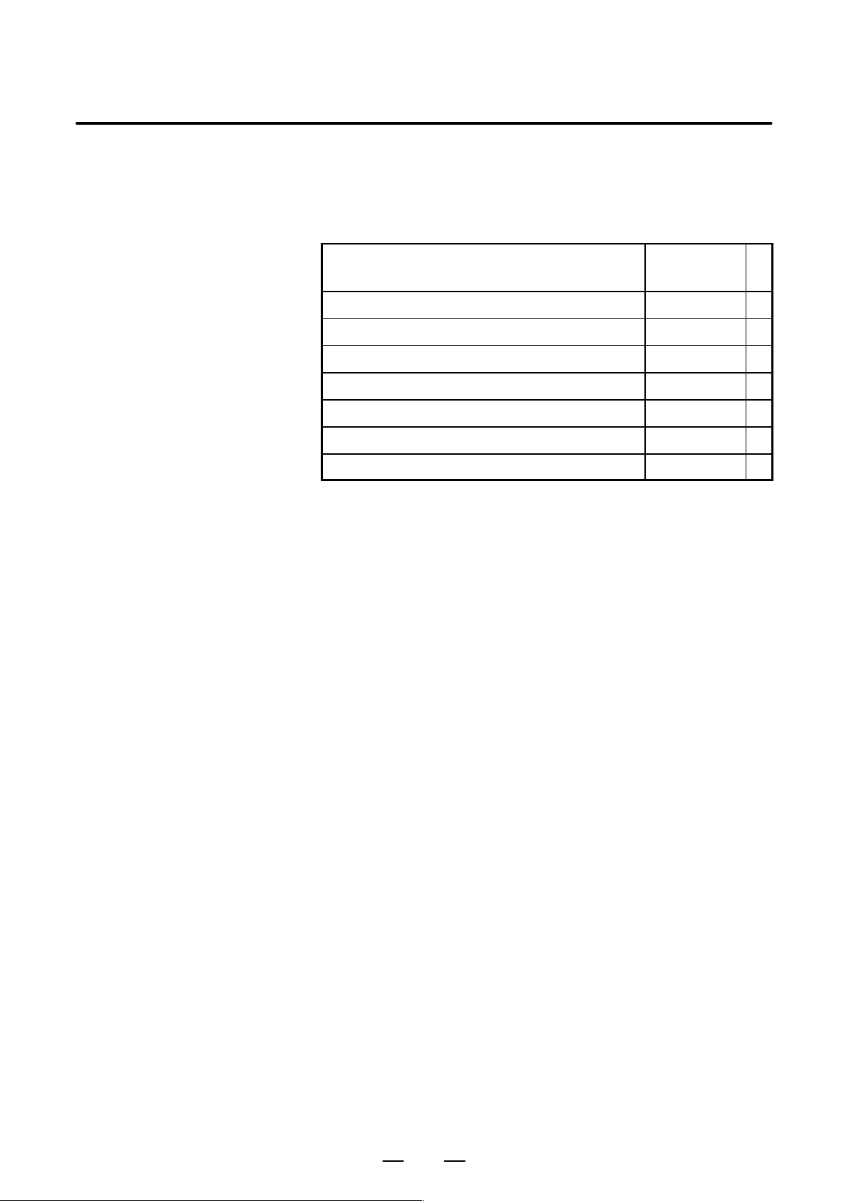
Table 1 Related manuals
Manual name
DESCRIPTIONS B–63782EN
CONNECTION MANUAL (Hardware) B–63783EN *
CONNECTION MANUAL (Function) B–63783EN–1
OPERATOR’S MANUAL (PROGRAMMING) B–63784EN
OPERATOR’S MANUAL (OPERATION) B–63784EN–1
MAINTENANCE MANUAL B–63785EN
PARAMETER MANUAL B–63790EN
Specification
number
3
Page 16

2. CONFIGURATION
CONFIGURATION
2
B–63783EN/01
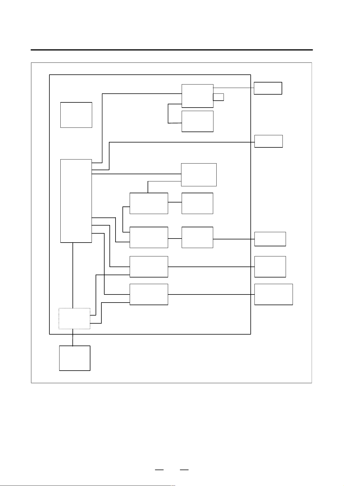
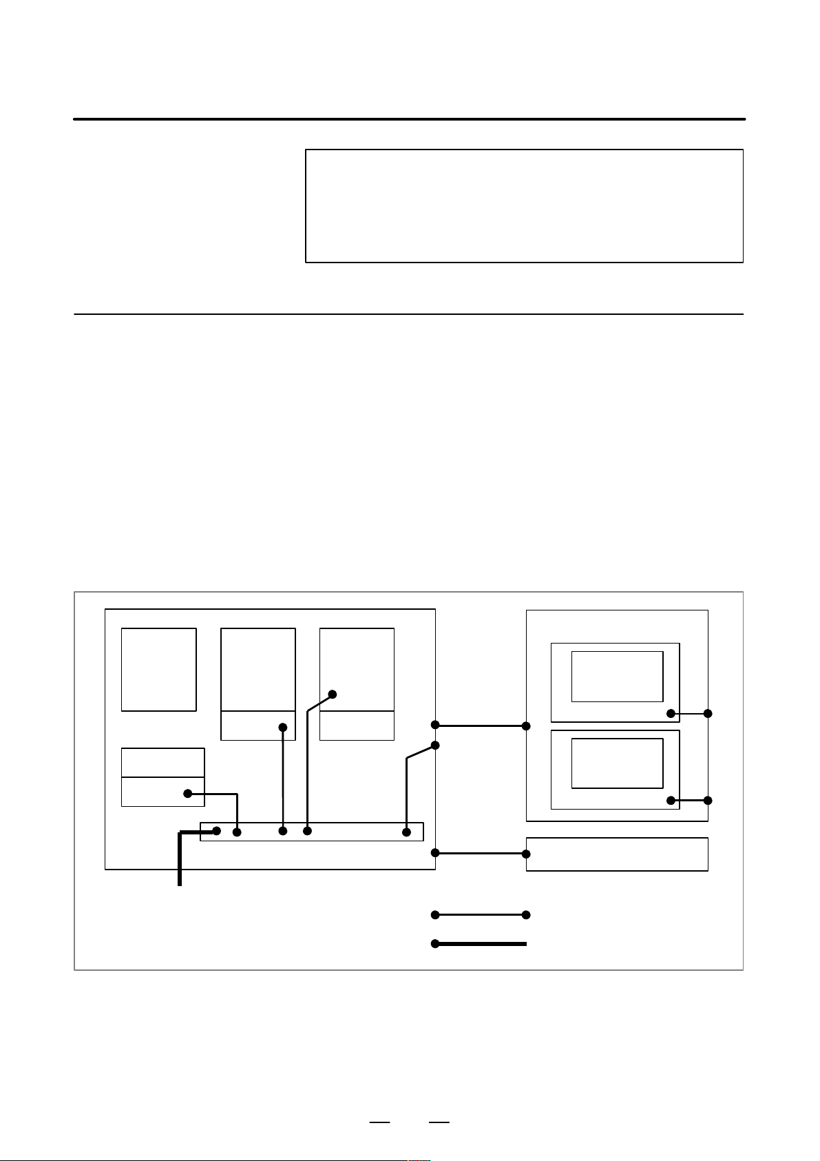
The following figure shows the configuration of the electrical system of
the machine tool with which this control is used.
This manual describes how to connect the units illustrated in this diagram.
The machine tool body, machine operator’s panel, power magnetic
circuit, and sensor/actuator are specific to the machine tool and are the
builder’s responsibility. This manual does not cover the internal
connection of these units to the machine tool.
4
Page 17
B–63783EN/01
Machine tool magnetics cabinet
Heat
exchanger
LCD unit
MDI unit
2. CONFIGURATION
I/O unit
Memory card
I/O unit
CNC
Export
transformer
Operator’s
panel I/O unit
Wiring panel
I/O unit
Servo
amplifier
Spindle
amplifier
Manual pulse
generator
Machine
operator’s
panel
Power magnetics cabinet
control circuit
Sensors
Servo
motor
Spindle motor
Distribution
board
5
Page 18

3. INSTALLATION
INSTALLATION
3
B–63783EN/01
6
Page 19
B–63783EN/01
3.1
ENVIRONMENTAL REQUIREMENTS OUTSIDE THE CABINET
3. INSTALLATION
3.1.1
Environmental Conditions Around the Cabinet
The peripheral units and the control unit have been designed on the
assumption that they are housed in closed cabinets. In this manual
“cabinet” refers to the following:
D Cabinet manufactured by the machine tool builder for housing the
control unit or peripheral units;
D Operation pendant, manufactured by the machine tool builder, for
housing the control unit or operator ’s panel.
D Equivalent to the above.
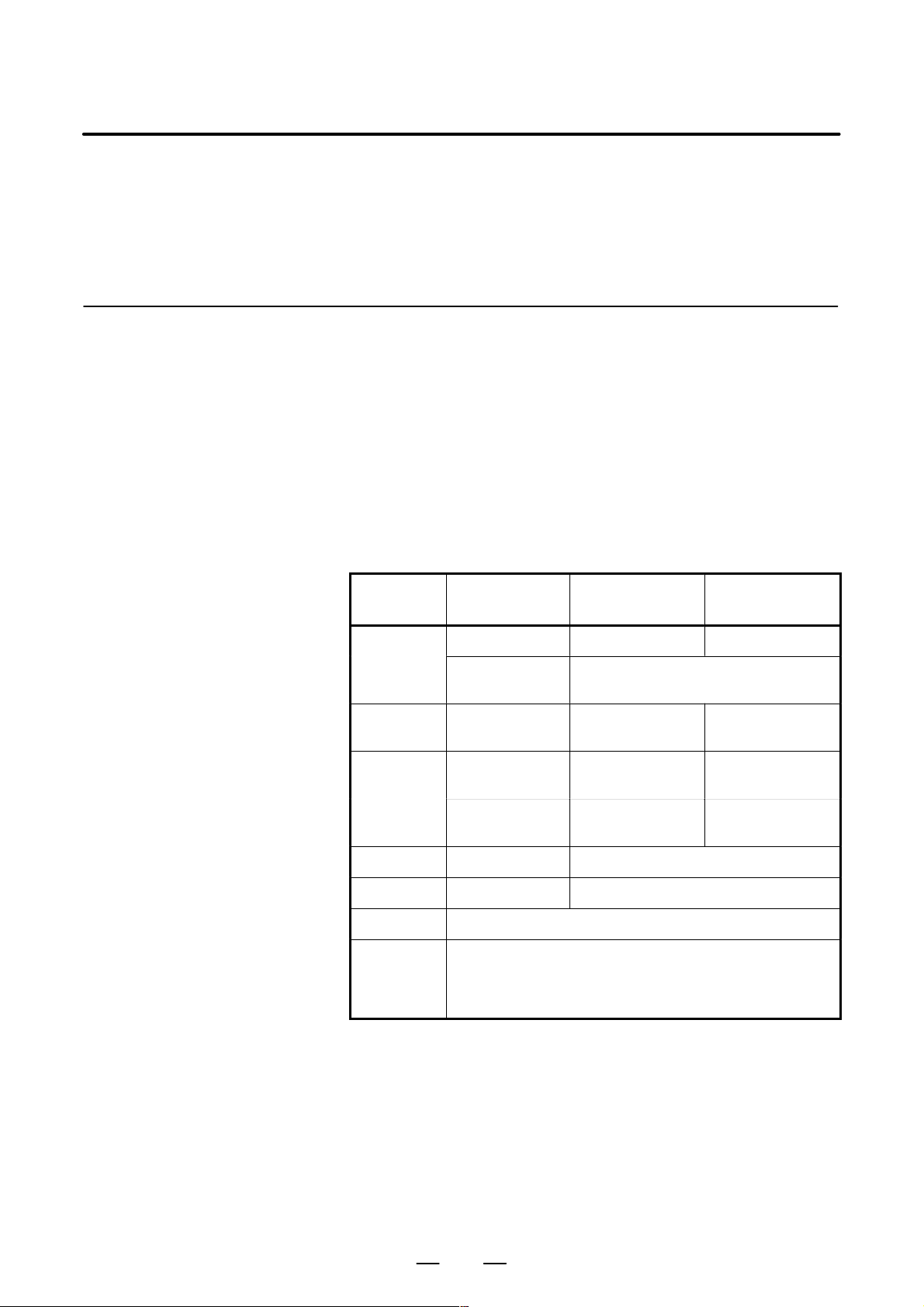
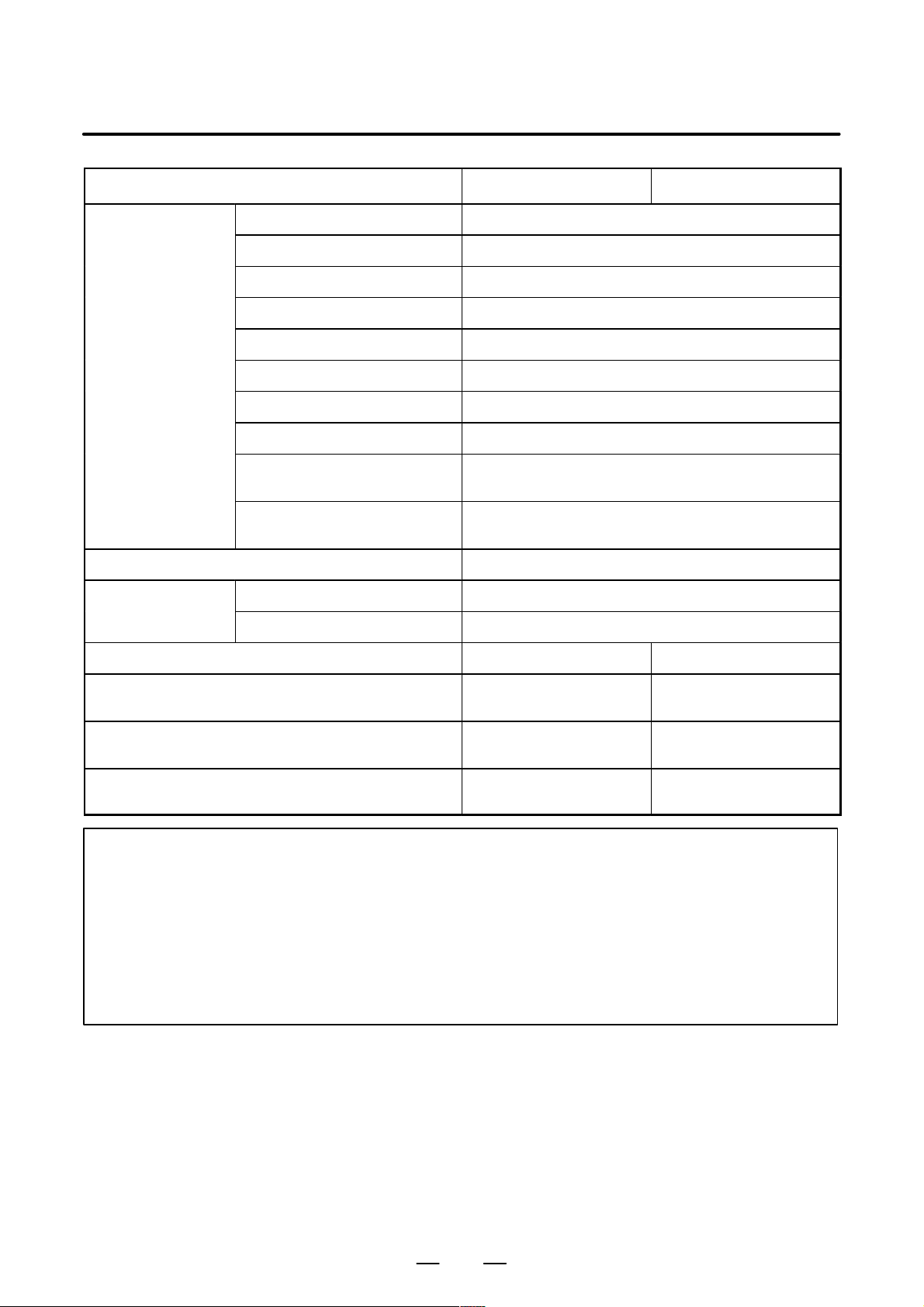
The environmental conditions when installing these cabinets shall
conform to the following table. Section 3.3 describes the installation and
design conditions of a cabinet satisfying these conditions.
Ambient
Temperature
Temperature
Change
Humidity
Condition
Operating 0°C to 45°C 5°C to 40°C
Storage,
Transport
Normal
Short period (less
than 1 month)
Case of not using
hard disk
–20°C to 60°C
Max. 0.3°C/min. Max. 0.3°C/min.
75%RH or less, no
condensation
95%RH or less, no
condensation
Case of using
hard disk
10% to 75%RH, no
condensation
10% to 90%RH, no
condensation
Vibration Operating 0.5 G or less
Vibration Non–operating 1.0 G or less
Altitude 1000 m or less
Normal machine shop environment
Environment
(The environment must be considered if the cabinets are in a
location where the density of dust, coolant, and/or organic
solvent is relatively high.)
7
Page 20
3. INSTALLATION
3.1.2
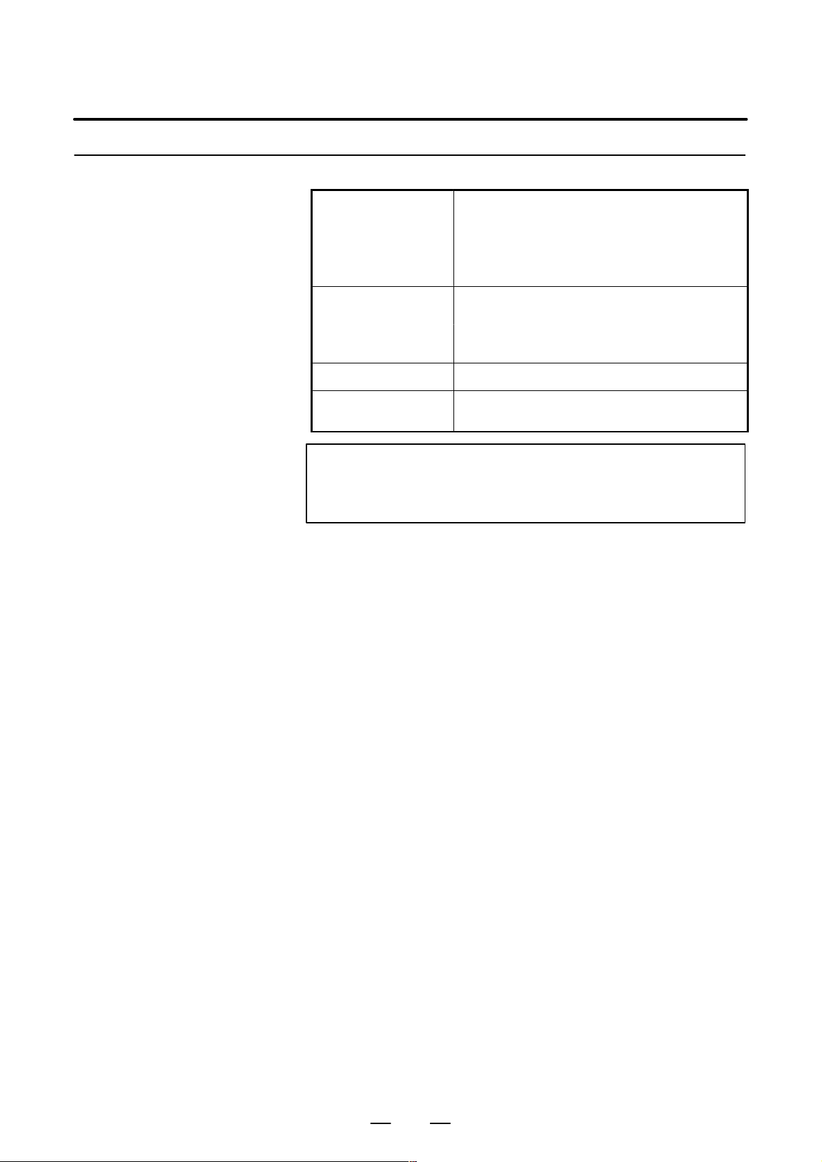
Installation Conditions for the CNC and Servo Unit Inside the Cabinet
Operating: 0°C to 55°C
(no hard disk drive used)
Ambient temperature
Humidity
Vibration 0.5 G or less
Operating: 5°C to 50°C
(hard disk drive used)
Storage and transportation: –20°C to 60°C
95% or less (relative) with no condensation
(no hard disk drive used)
75% or less (relative) with no condensation
(hard disk drive used)
B–63783EN/01
Environment
The unit shall not be exposed direct to cutting oil,
lubricant or cutting chips.
NOTE
When using the CNC display unit with PC functions, also
see Subsection 10.5.1.
8
Page 21

B–63783EN/01
3. INSTALLATION
3.2
POWER REQUIREMENTS
The power requirement of the CNC control unit is calculated as the sum
of the power required by the control and servo sections.
The control section power requirement includes the power required for
control, the LCD, I/O units, the operator panel interface, and the
on/off–controlled 200 V AC service outlet (2.5 A maximum) for the power
supply unit.
Control section power
requirement
Servo section power requirement Varies with the type of related servo motor
1.2 KV A
9
Page 22

3. INSTALLATION
B–63783EN/01
3.3
DESIGN AND INSTALLATION CONDITIONS OF THE MACHINE TOOL MAGNETIC CABINET
When a cabinet is designed, it must satisfy the environmental conditions
described in Section 3.1. In addition, the magnetic interference on the
screen, noise resistance, and maintenance requirements must be
considered. The cabinet design must meet the following conditions :
D The cabinet must be fully closed.
The cabinet must be designed to prevent the entry of airborne
dust,coolant,and organic solvent.
D The cabinet to hold the control unit must be designed to maintain a
difference in temperature of up to 10°C between the air in the cabinet
and the outside air when the temperature in the cabinet rises.
For details of the thermal design, see 3.4.
D A closed cabinet must be equipped with a fan to circulate the air
within. (This is not necessary for a unit with fan.)
The fan must be adjusted so that the air moves at 0.5 m/sec along the
surface of each installed unit.
CAUTION : If the air blows directly from the fan to the unit, dust
easily adheres to the unit. This may cause the unit to fail.
D For the air to move easily, a clearance of 100 mm is required between
each unit and the wall of the cabinet. (This is not necessary for a unit
with fan.)
D Packing materials must be used for the cable port and the door in order
to seal the cabinet.
D The LCD unit and MDI unit must not be installed in such a place that
coolant would directly fall onto the unit.
The front panels of the LCD unit and the MDI unit are dustproof.
However, avoid installing the units in locations where their front
panels directly receive coolant. For an explanation of the dust
protection measures for the power magnetics cabinets and pendant
boxes of machine tools, see Section 3.4.
D Noise must be minimized.
As the machine and the CNC unit are reduced in size, the parts that
generate noise may be placed near noise–sensitive parts in the
magnetics cabinet.
The CNC unit is built to protect it from external noise. Cabinet design
to minimize noise generation and to prevent it from being transmitted
to the CNC unit is necessary. See section 3.6 for details of noise
elimination/management.
D When determining the layout of units in the cabinet, consider
maintainability; arrange the units in such a way that they can be easily
replaced during maintenance and inspection.
D The hard disk drive and floppy disk drive must not be installed near
the source of a strong magnetic field.
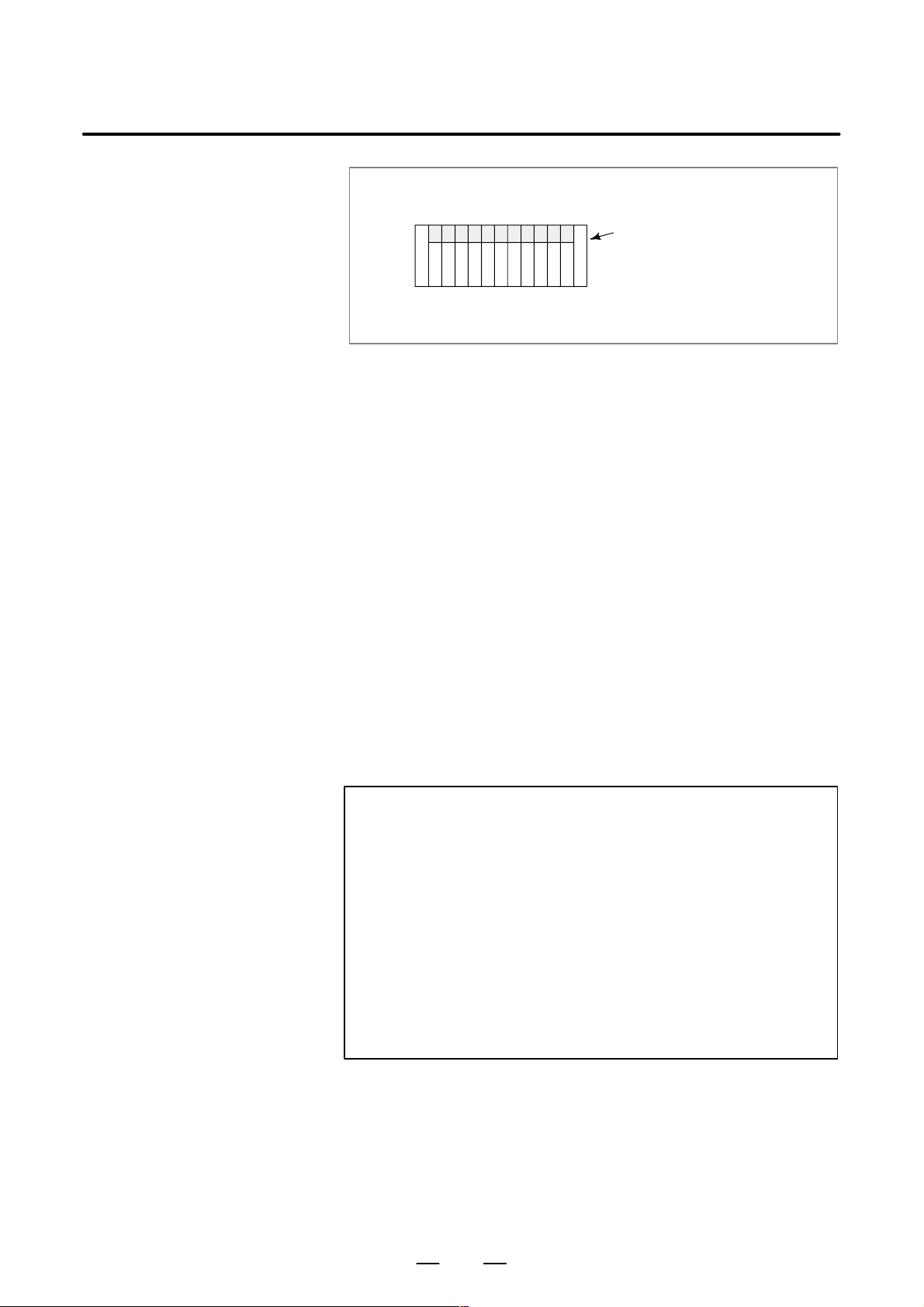
D The installation conditions of the I/O unit and connector panel I/O
module must be satisfied.
To obtain good ventilation in the module, the I/O unit and connector
panel I/O module must be installed in the direction shown in the
following figure. Clearances of 100 mm or more both above and
below the I/O unit are required for wiring and ventilation.
Equipment radiating too much heat must not be put below the I/O unit
and connector panel I/O module.
10
Page 23
B–63783EN/01
3. INSTALLATION
Top
Bottom
Connector panel I/O module or
I/O base unit
(No screws or protrusions shall
extend from the bottom of this
unit.)
D If the CNC unit is installed at an altitude of over 1,000 m, an upper
limit is placed on the ambient temperature (one of the environmental
conditions described in Section 3.1) for the CNC within the cabinet.
Each increment of 100 m over 1,000 m requires that 1.0°C be
subtracted from the maximum allowable ambient temperature for the
CNC in the cabinet.
Example) If a cabinet containing the CNC is installed at an altitude
of 1,750 m, the maximum allowable ambient temperature
for the CNC is: 55°C – 750/100 × 1.0°C = 47.5°C
The allowable ambient temperature range for the CNC is therefore
from 0°C to 47.5°C.
If the hard disk drive in the CNC is used, the CNC can be installed only
at an altitude ranging from:
–60 to 3,000 m when in operation
–60 to 12,000 when not in operation
D Unspecified frequencies may cause the CNC control unit and hard disk
drive to vibrate at their resonance frequency, possibly subjecting unit
components to an acceleration higher than allowable. After mounting
the CNC control unit on your machine, carefully check for any
abnormal conditions.
CAUTION
For a control unit with a hard disk, data stored on the hard
disk may be destroyed due to operator errors or accidents
even when the environmental conditions above are
satisfied. To guard against such data loss, back up the
important hard disk data regularly. In particular, never turn
off the power, even momentarily , while the hard disk is being
accessed or the operating system is running, as doing so is
highly likely to destroy part of the contents of the disk. End
users should be made fully aware of this, to ensure that they
do not inadvertently lose important data.
11
Page 24
3. INSTALLATION
B–63783EN/01
3.4
PROTECTION OF PARTS INSIDE A CABINET OR A PENDANT BOX FROM DUST
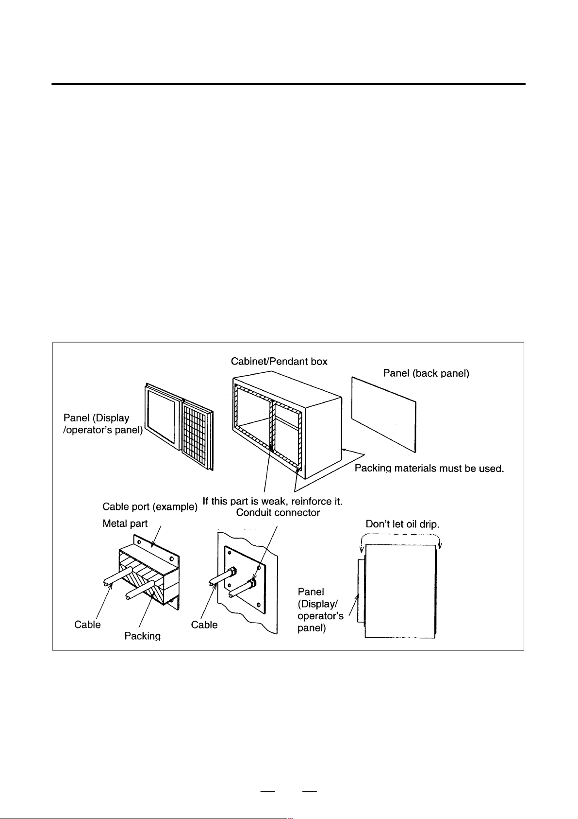
When a cabinet or a pendant box, which houses a display and an operator’s
panel, is designed, it must satisfy following conditions to prevent from
the entry of airborne dust, coolant, and organic solvent.
(1) A cabinet or a pendant box must be fully closed.
(2) Packing materials must be used for the fixed side of a display and an
operator’s panel in order to seal a cabinet or a pendant box.
(3) Packing materials must be used for the door of a cabinet or a pendant
box in order to seal a cabinet or a pendant box.
(4) Packing materials must be used for a back panel in order to seal a
cabinet or a pendant box.
(5) Packing materials and conduit connector and so on must be used for
the cable port in order to seal a cabinet or a pendant box.
(6) ALL holes must be filled.
(7) A display and an operator ’s panel must not be placed in a location
where coolant and cutting chips would directly fall onto them.
(8) Don’t let oil drip from the top of a cabinet or a pendant to panel sides.
12
Page 25

B–63783EN/01
3. INSTALLATION
3.5
THERMAL DESIGN OF THE CABINET
3.5.1
Temperature Rise within the Cabinet
The purpose of the thermal design of the cabinet is to limit the difference
in temperature between the air in the cabinet and the outside air to 10°C
or less when the temperature in the cabinet increases.
The internal air temperature of the cabinet increases when the units and
parts installed in the cabinet generate heat. Since the generated heat is
radiated from the surface of the cabinet, the temperature of the air in the
cabinet and the outside air balance at certain heat levels. If the amount
of heat generated is constant, the larger the surface area of the cabinet, the
less the internal temperature rises. The thermal design of the cabinet
refers to calculating the heat generated in the cabinet, evaluating the
surface area of the cabinet, and enlarging that surface area by installing
heat exchangers in the cabinet, if necessary. Such a design method is
described in the following subsections.
The cooling capacity of a cabinet made of sheet metal is generally 6 W/°C
per 1m
cabinet having a surface area of 1 m
cabinet rises by 1°C. In this case the surface area of the cabinet refers to
the area useful in cooling , that is, the area obtained by subtracting the area
of the cabinet touching the floor from the total surface area of the cabinet.
There are two preconditions : The air in the cabinet must be circuited by
the fun, and the temperature of the air in the cabinet must be almost
constant.The following expression must then be satisfied to limit the
difference in temperature between the air in the cabinet and the outside air
to 10°C or less when the temperature in the cabinet rises:
Internal heat loss P [W] x
6[W/m
For example, a cabinet having a surface area of 4m
of 24W/°C. T o limit the internal temperature increase to 10°C under these
conditions, the internal heat must not exceed 240W. If the actual internal
heat is 320W, however, the temperature in the cabinet rises by 13°C or
more. When this happens, the cooling capacity of the cabinet must be
improved using the heat exchanger described next.
2
surface area, that is, when the 6W heat source is contained in a
2
⋅°C] × surface area S[m2]×10[°C] of rise in temperature
2
, the temperature of the air in the
2
has a cooling capacity
3.5.2
Cooling by Heat Exchanger
If the temperature rise cannot be limited to 10°C by the cooling capacity
of the cabinet, a heat exchanger must be added. The heat exchanger
forcibly applies the air from both the inside and outside of the cabinet to
the cooling fin to obtain effective cooling. The heat exchanger enlar ges
the surface area.
Example
2
For a cabinet with a surface area of 4 m
radiation capacity of 9 W/°C is used, the total heat radiation capacity
increases to
6W/m
This means that even if the internal heat generation is 320 W, the
temperature rise is held below 10 °C.
2
⋅°C × 4m2⋅+⋅9W/°C = 33W/°C
13
, if a heat exchanger with a heat
Page 26

3. INSTALLATION
3.5.3
Calorific Value of Each Unit
Product name Calorific value Remarks
B–63783EN/01
Control unit
Basic unit (2 slots) 64W
Basic unit (4 slots) 68W
Main CPU board 38W
Additional axis board 10W
HSSB board 4W
Data server board A1 6W
Data server board A2 6.3W Including the 0.3 W of the
A T A card(*1)
Fast data server 6.3W Including the 0.3 W of the
A T A card(*1)
PMC C–language board 7W
Serial communication board 7W
DeviceNet board B 5W
DeviceNet board C 4W
Profibus board (master) 4W
Profibus board (slave) 6W
Etehrnet board 6W
Fast Ethernet board 6W
LCD unit
Hard disk unit for data server 13W
Separate detector
interface unit
Connection unit
Operator’s panel connection unit 3.6W + 0.18 W × Number of ONs
I/O unit model A
10.4″ color LCD unit 20W
9.5″ monochrome LCD unit 18W
Basic unit 9W (*2)
Basic unit + Additional unit 14W (*2)
Connection unit 1 16W + 0.18W × Number of ON inputs
Connection units 1 and 2 25W + 0.18W × Number of ON inputs
AIF01A, AIF01B 1.2W
AID32A, AID32B 1.2W + 0.23W × Number of ON inputs
AID16A, AID16B 0.1W + 0.21W × Number of ON inputs
AID32E, AID32F 0.1W + 0.23W × Number of ON inputs
14
Page 27
B–63783EN/01
3. INSTALLATION
Product name RemarksCalorific value
I/O unit model B
I/O module for operator’s panel 3.6W + 0.18W × Number of ON inputs
I/O module for con-
nector panel
Exported transformer for control unit 51W
BIF04A1 1.6W
AIF02C 1.2W
BID16A1, BID16B1 1.5W + 0.23 × Number of ON inputs
BID16P1, BID16Q1 0.6W + 0.23 × Number of ON inputs
BOA12A1 0.9W + (0.09 + 1.1 × IL2) x Number of ON outputs
BOD16A1 1.0W + (0.13 + 0.3 × IL2) Number of ON outputs
BOD16P1 0.3W + (0.13 + 0.3 × IL2) x Number of ON outputs
BIA16P1 0.1W + 0.21 × Number of ON inputs
BMD88A1, BMD88B1 1.3W + 0.23 × Number of ON input points +
(0.13 + 0.3 × IL
BMD88P1, BMD88Q1 0.4W + 0.23 × Number of ON input points +
(0.13 + 0.3 × IL
Basic unit 3.6W + 0.18W × Number of ON inputs
Extension unit 3.6W + 0.18W × Number of ON inputs
2
) × Number of ON output points
2
) × Number of ON output points
CNC display unit with PC functions 10.4”
(A13B–0193–B031 to –B038)
CNC display unit with PC functions 12.1”
(A13B–0193–B041 to –B048)
CNC display unit with PC functions 15.0”
(A13B–0193–B051 to –B057)
40W During normal operation (*3)
52W During normal operation (*3)
52W During normal operation (*3)
NOTE
1 The calorific value of the ATA flash card is subject to change because of the adoption of a
large–capacity card, changes in the card specifications, and so on.
2 Does not include the calorific value of the heat generated inside the separate detector.
3 Units assumed to be active during normal operation: CNC display unit with PC functions, HDD
unit, HDD fan, FDD unit, full keyboard, and mouse. Units assumed to be inactive during normal
operation: PCMCIA card, serial interface expansion device, parallel–interface–connected
device. Note that the generated heat will increase if peripheral devices and PCI expansion
boards are connected.
15
Page 28
3. INSTALLATION
B–63783EN/01
3.6
ACTION AGAINST NOISE
3.6.1
Separating Signal Lines
The CNC has been steadily reduced in size using surface–mount and
custom LSI technologies for electronic components. The CNC also is
designed to be protected from external noise. However, it is difficult to
measure the level and frequency of noise quantitatively, and noise has
many uncertain factors. It is important to prevent both noise from being
generated and generated noise from being introduced into the CNC. This
precaution improves the stability of the CNC machine tool system.
The CNC component units are often installed close to the parts generating
noise in the power magnetics cabinet. Possible noise sources into the
CNC are capacitive coupling, electromagnetic induction, and ground
loops.
When designing the power magnetics cabinet, guard against noise in the
machine as described in the following section.
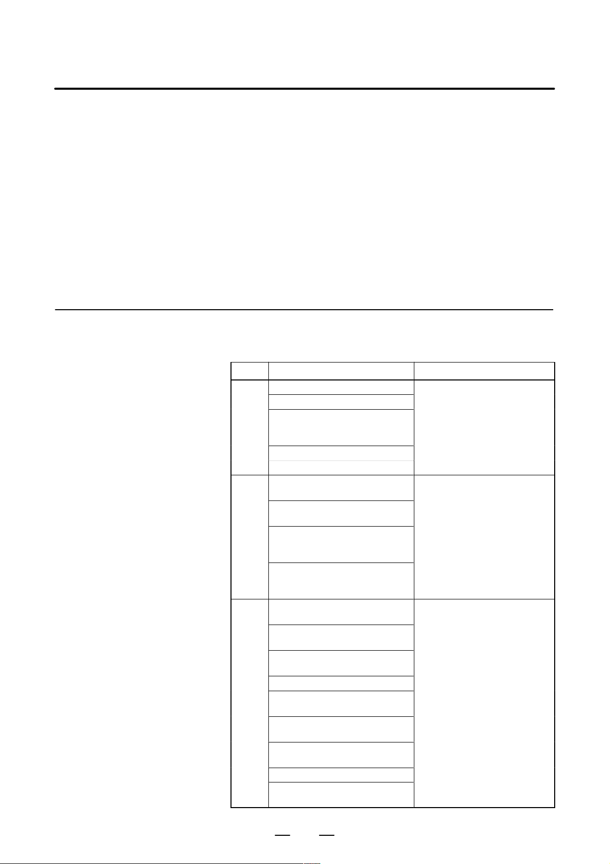
The cables used for the CNC machine tool are classified as listed in the
following table:
Process the cables in each group as described in the action column.
Group Signal line Action
Primary AC power line
Secondary AC power line
AC/DC power lines (containing
the power lines for the servo and
A
spindle motors)
AC/DC solenoid
AC/DC relay
DC solenoid (24VDC)
DC relay (24VDC)
DI/DO cable between the I/O unit
B
and power magnetics cabinet
DI/DO cable between the I/O unit
and machine
Cable between the CNC and I/O
unit
Cable for position and velocity
feedback
Cable between the CNC and
spindle amplifier
Cable for the position coder
Cable for the manual pulse gen-
C
erator
Cable between the LCD and the
MDI
RS–232C and RS–422 interface
cable
Cable for the battery
Other cables to be covered with
the shield
Bind the cables in group A separately (Note 1) from groups B
and C, or cover group A with an
electromagnetic shield (Note 2).
See Section 3.6.4 and connect
spark killers or diodes with the
solenoid and relay.
solenoid and relay.
Connect diodes with DC solenoid and relay .
Bind the cables in group B separately from group A, or cover
group B with an electromagnetic
shield.
Separate group B as far from
Group C as possible.
It is more desirable to cover
group B with the shield.
Bind the cables in group C separately from group A, or cover
group C with an electromagnetic
shield.
Separate group C as far from
Group B as possible.
Be sure to perform shield processing in Section 3.6.5.
16
Page 29
B–63783EN/01
3. INSTALLATION
NOTE
1 The groups must be 10 cm or more apart from one another
when binding the cables in each group.
2 The electromagnetic shield refers to shielding between
groups with grounded steel plates.
3.6.2
Grounding
Distributed
I/O
α Tamplifier
AC power
The CNC machine tool has three grounding systems:
D Grounding system for signals
The grounding system for signals provides the reference potential (0
V) for the electric signal system.
D Protective grounding system
The protective grounding system is intended to ensure safety and
shield any external noise and internally–generated noise. It consists
of device frames, unit cases, panels, as well as the shields of the
interface cables connecting devices.
D Protective earth (PE) system
The protective earth (PE) system connects the protective grounding
system, which is provided for devices and units, to ground at a single
location.
Pendant box
CNC
Display
Frame
AC power
24–V power
AC input
PE (grounding plate of the cabinet)
Operator’s
panel
Frame
Machine cabinet
Connection line for grounding
Connection line for the
protective earth (PE) system
17
Page 30
3. INSTALLATION
B–63783EN/01
Notes on wiring for the
grounding systems
3.6.3
Grounding Units
D The ground resistance of the protective earth (PE) system must be
100 Ω or less (as per class–D grounding).
D The connection cable for the protective earth (PE) system must be so
large in cross section that the accidental current can flow through the
protective earth (PE) system safely in the event of an accident such as
a short–circuit.
(In general, the cross section must be equal to or greater than that of
the AC power line.)
D The connection cable for the protective earth (PE) system must be
integral with the AC power line so that the power is not supplied when
the grounding line is disconnected.
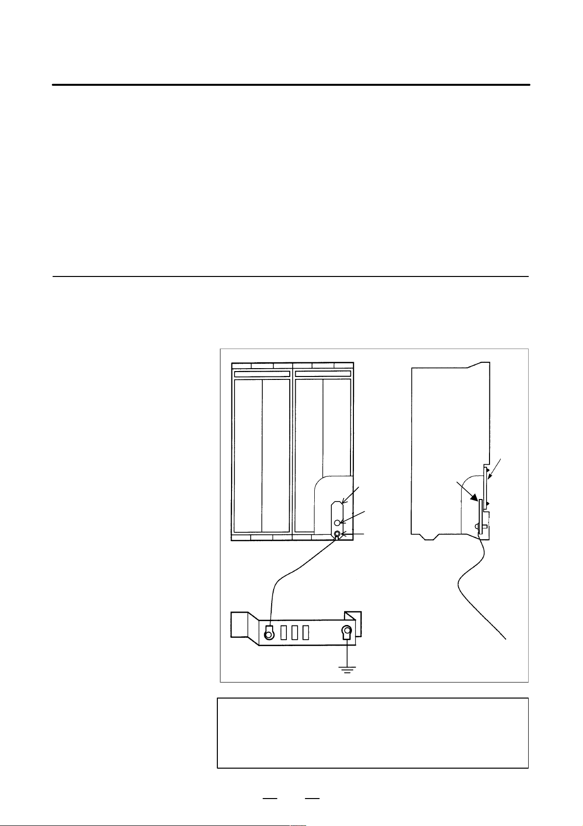
(a)Control unit
Connect the 0V line of the electronic circuits inside the control unit to
the earth plate on the cabinet via the signal ground (SG) terminal
(bottom front of main board).
Signal
Earth cable
(Twisted wire earth cable lead
2mm2 or more)
Cabinet ground plate
ground
(SG)
M4
(mounting
hole)
M3
(screw
terminal)
System ground
SG
Earth cable
NOTE
Connect an twisted wire earth cable lead 2mm
2
or more to
the earth plate on the cabinet keeping the lead as short as
possible.
Plate
M3
18
Page 31

B–63783EN/01
3. INSTALLATION
(b)Display unit
(rear view)
Cover
(c)MDI unit
CK2
COP20
(rear view)
PCB
CP1
B
A
M4 stud for earth connection
19
CK1
M4 stud for earth connection
Page 32

3. INSTALLATION
B–63783EN/01
(d)Connection units 1, 2
M4 screw
(e)Operator’s panel connection unit
Install an
installation plate.
(f) I/O unit model A
Connect the grounding terminals of ABU05A, ABU05B, ABU10A and ABU10B.
ABU05A, ABU10A ABU05B, ABU10B
M4 screw terminal
for grounding
SG terminal
(M3 screw terminal)
M4 mounting hole
for grounding
Note) Connect the SG terminal to the earth mounting hole.
NOTE
Connect the SG terminal to the grounding mounting hole.
20
Page 33

B–63783EN/01
3. INSTALLATION
(g)Hard disk unit
Control unit
Grounding terminal
for signals
Printed circuit board
Hard disk unit
Grounding cable
Grounding cable
Grounding plate of the
cabinet
Grounding terminal for signals
M3 terminal block (FG1)
NOTE
Connect the grounding cable of the hard disk unit via the grounding terminal for signals that
is located on the control unit. (Do not connect the cable directly to the grounding plate of the
cabinet.)
(h)External power supply
When using an external DC power supply for the units, be sure to
ground the 0 V terminal of the power supply.
21
Page 34

3. INSTALLATION
B–63783EN/01
3.6.4
Noise Suppresser
AC/DC solenoids and relays are used in the power magnetics cabinet.
A high pulse voltage is caused by coil inductance when these devices are
turned on or off.
This pulse voltage induced through the cable causes the electronic circuits
to be disturbed.
Generally, to reduce this pulse voltage, use a spark killer when an AC
power source is used, and a diode when a DC power source is used.
Notes on selecting the spark killer
D Use a CR spark killer.
(A varistor is useful in clamping the peak voltage of the pulse voltage,
but cannot suppress the sudden rise of the pulse voltage. FANUC
therefore recommends a CR spark killer.)
D The reference capacitance and resistance of the spark killer shall
conform to the following based on the current (I (A)) and DC
resistance of the stationary coil:
1) Resistance (R): Equivalent DC resistance of the coil
2
2) Capacitance (C): I
Equivalent circuit of the spark killer
/10 to I2/20 (µF)
CR
AC relay
Spark killer
Spark killer
Motor
22
Page 35

B–63783EN/01
3. INSTALLATION
3.6.5
Cable Clamp and Shield Processing
The CNC cables that require shielding should be clamped by the method
shown below. This cable clamp treatment is for both cable support and
proper grounding of the shield. To ensure stable CNC system operation,
follow this cable camp method.
Partially peel out the sheath and expose the shield. Push and clamp by the
plate metal fittings for clamping the part.
Metal fittings for clamp are supplied with the CNC.
The ground plate must be made by the machine tool builder, and set as
follows:
Ground plate
Cable
Metal fittings
for clamp
23
40 mm to 80 mm
Fig. 3.6.5 (a) Cable clamp (1)
Page 36

3. INSTALLATION
B–63783EN/01
Machine side
installation
board
Control unit
Ground plate
Metal fittings
for clamp
Shield cover
Fig. 3.6.5 (b) Cable clamp (2)
Prepare ground plate like the following figure.
Hole for securing metal fitting clamp
Mount screw hole
Fig. 3.6.5 (c) Ground plate
Ground terminal
(grounded)
For the ground plate, use a metal plate of 2 mm or thicker, which surface
is plated with nickel.
24
Page 37

B–63783EN/01
3. INSTALLATION
8mm
12mm
20mm
Fig. 3.6.5 (d) Ground plate holes
(Reference) Outer drawings of metal fittings for clamp.
Max. 55mm
Ground
plate
28mm
6mm
17mm
Fig. 3.6.5 (e) Outer drawings of metal fittings for clamp
Ordering specification for metal fittings for clamp
A02B–0118–K001 (5 pieces)
NOTE
Select cables of appropriate length.
Cables longer than necessary are not recommended. If
cables longer than necessary are used, their resistance to
noise may be reduced or noise may be induced on other
cables. If surplus cable is wound up, inductance increases
and an extremely high voltage may be induced during
ON/OFF switching. This may result in malfunction or
erroneous operation caused by noise.
25
Page 38

3. INSTALLATION
B–63783EN/01
3.7
MEASURES AGAINST SURGES DUE TO LIGHTNING
3.7.1
Installation Procedure of Surge Protector
To protect the devices from surge voltages due to lightening, it is
recommended to install surge–absorbing elements between the lines of
the input power and between one line and ground. This does not,
however, assures protection from all surges due to lightening.
NOTE
The device might break by lightning even when the
surge–absorbing elements is installed.
The surge–absorbing elements used for measures against surges due to
lightening must be installed in the input power unit as shown in the figure
below. The figure below shows an example in which an insulating
transformer, shown by dotted line, is not installed. If an insulating
transfer is installed, surge–absorbing element <2> (between line and
ground) is not required.
Nonfuse
breaker
To CNC
AC
input
R
S
T
PE
Input
breaker
Insulating
transformer
Nonfuse
breaker
5A
Nonfuse
breaker
b
a
Surge–absorbing element <2>
(between line and ground)
MCC
T o other electric parts on the machine
Surge–absorbing element <1>
(between lines)
AC
reactor
Servo unit
power supply
module
26
Page 39

B–63783EN/01
3. INSTALLATION
3.7.2
Notes
3.7.3
Examples of Surge Protectors
(1) For better surge absorbing effect, the wiring shown by heavy line in
Fig. 3.7.1 (a) must be as short as possible.
2
Wire:The wire size must be 2 mm
or greater.
Wire length: The sum of the wire for the connection of surge
protector <1> a and that of surge protector <2> b
must be 2 m or less.
(2)If conducting dielectric strength tests by applying overvoltages (1000
VAC and 1500 VAC) to the power line, remove surge protector <2>.
Otherwise, the overvoltages will activate the protector.
(3) The nonfuse breaker (5A) is required for line protection if a surge
exceeding the capacity of the surge protectors is applied, causing the
surge protectors to be short–circuited.
(4)Because no current flows through surge protectors <1> and <2> during
normal operation, the nonfuse breaker (5A) can be shared by other
devices. It can be connected to the control power for the power supply
module and to the power for the fan motor of the spindle motor.
For the surge absorbers made by Okaya Denki Sangyo Co.
For the 200–V system
Between lines R·A·V–781BYZ–2
Between line and ground R·A·V–781BXZ–4
For the 400–V system
Between lines R·A·V–152BYZ–2A
Between line and ground R·A·V–801BXZ–4
27
Page 40

3. INSTALLATION
3.8
CONTROL UNIT
B–63783EN/01
3.8.1
Configuration and Installation of the Control Unit
Additional axis board
The Series 15i/150i control boards are mounted on the rack having two
or more slots.
Fast data server Main CPU board
1 PSU32
Power supply unit
2 slots
4 slots
Fig. 3.8.1 (a) Configuration of Series 15i/150i control unit
Mounting position
Slot PSU Power supply unit
Slot 1 Main CPU board
Slot 2 Fast data server
Slot 3 Additional axis board
28
Name of board
Page 41

B–63783EN/01
Ô
Ô
Ô
Ô
Ô
Ô
Ô
Ô
50
The rack is made of plastic, and comprises a fan motor and backplane
board.
The fan motor is mounted on the rack. Air enters the rack from the bottom,
and exits from the fan motor mounted at the top.
Make sure that the space shown in Fig. 3.8.1(b) ((1) and (2)) is maintained
to ensure air flow. (1) is necessary for replacing the fan.
When a hard disk is used as the data server, hard disk installation area (4)
is required. (The external dimensions of the hard disk are subject to
change without notice in the interest of product improvement. Before you
design a rack using the hard disk contact FANUC regarding the outside
dimensions of the hard disk.)
Maintain the following space for ensuring air flow and replacing the fan.
(1)
3. INSTALLATION
Approx. 172
(1)
50
380
(2)
2 slots: 1 12
4 slots: 224
Hard disk installation
(4)
area
38
59
131
35
112
(3)
See Appendix A for detais of
dimension of the hard disk unit.
80
(2)
Unit: mm
Fig. 3.8.1 (b) Installation of the control unit
29
Page 42

3. INSTALLATION
B–63783EN/01
3.8.2
Replacing the Battery for Memory Backup
Replacing the lithium
battery
Part programs, offset data, and system parameters are stored in CMOS
memory in the control unit. The power to the CMOS memory is baked up
by a lithium battery mounted on the front panel of the control unit. The
above data is not lost even when the main battery goes dead. The backup
battery is mounted on the control unit at shipping.
When the voltage of the battery becomes low, alarm message “BAT”
blinks on the LCD display and the battery alarm signal is output to the
PMC.
If an alarm is issued, replace the battery within one week. Otherwise, the
contents of the memory will be lost.
If the voltage of the battery becomes any lower, memory can no longer
be backed up. Turning on the power to the control unit in this state causes
system alarm [screen display: RAM parity error (low battery voltage)] to
occur as the contents of memory are lost. Clear the entire memory and
reenter data after replacing the battery.
Before replacing the memory backup battery, the control unit power off.
The following two kinds of batteries can be used.
D Lithium battery built into the main board of the Series 15i/150i.
D Two alkaline dry cells (size D) in the external battery case.
Procedure
(1) Prepare a new lithium battery (A02B–0200–K102).
(2) Turn the control unit on for about 30 seconds.
(3) Turn the control unit off.
(4) Remove the old battery from the top of the main board.
First, remove the claws holding the battery, and then remove the
battery from the battery holder and disconnect the connector.
(5) Replace the battery, insert the battery into the battery holder, and
connect the connectors. Make sure that the battery holder claws are
firmly holding the battery in place.
Lithium battery
Battery holder claw
Memory card
connector
Fig. 3.8.2 Replacing the lithium battery
30
Battery
connector
BAT1
Main board
Page 43

B–63783EN/01
3. INSTALLATION
WARNING
Using other than the recommended battery may result in the
battery exploding.
Replace the battery only with the specified battery
(A02B–0200–K102).
NOTE
Steps (3) to (5) should be completed within 30 minutes.
Do not leave the control unit without a battery for any longer
than the period, as this will result in the contents of memory
being lost.
If battery replacement may take longer than 30 minutes,
download all the data in CMOS memory to a memory card
so that CMOS memory can be restored if the contents of
memory are lost.
Dispose of used batteries as follows.
(1) Small quantities (less than 10)
Discharge the batteries and dispose of them as ordinary unburnable
waste.
(2) Large quantities
Please consult FANUC.
31
Page 44

3. INSTALLATION
B–63783EN/01
Replacing the alkaline
dry cells (size D)
(1) Prepare two new alkaline dry cells (size D).
(2) Turn the Series 15i/150i on.
(3) Remove the battery case cover.
(4) Replace the batteries, paying careful attention to their orientation.
(5) Replace the battery case cover.
NOTE
When replacing the dry cells while the power is off, use the
same procedure as that for lithium battery replacement
procedure, described above.
Dry cell × 2
Cover
Connection terminal
on the rear
Mounting hole × 4
Battery case
32
Page 45

B–63783EN/01
Use of alkaline dry cells
(size D)
3. INSTALLATION
Connection
Memory card
connector
Power from the external batteries is supplied through the connector to
which the lithium battery is connected. The lithium battery, provided as
standard, can be replaced with external batteries in the battery case
(A02B–0236–C281) according to the battery replacement procedures
described above.
Battery connector
BAT1
Battery case
Main board
NOTE
Install the battery case (A02B–0236–C281: 14–m cable) in a location where the batteries can
be replaced even when the control unit power is on.
The battery cable connector is attached to the control unit by means of a simple lock system.
To prevent the connector from being disconnected due to the weight of the cable or tension
within the cable, fix the cable section within 50 cm of the connector.
33
Page 46

3. INSTALLATION
3.9
CABLE–LEAD–IN
DIAGRAM
3.9.1
Control Unit Periphery Connector Layouts
B–63783EN/01
224
12.7 4
54
109
94
12.7 6
177
2
92
46
45
49
COP10A
1 PSU
CP3
COP20A
CA54
GND
CP5
CP4
CP2
CP1
100
CP6
36
166
3
CA54
CA54
108 57
Fig. 3.9.1 (a) Control unit connector installation pitch
34
17
Page 47

B–63783EN/01
CP3
CP2
CP1
3. INSTALLATION
Name of Connector Functions
CP1 AC input
CP2 AC output
CP3 AC output
F3
CP5
F4
PIL
CP6
CP4
ALM
F3 +24 E fuse
F4 +24V fuse
PIL Pilot lamp
CP5 +24V output
CP6 +24 E output
CP4 Power source control
ALM Alarm lamp
Fig. 3.9.1 (b) Power supply unit connector layout
35
Page 48

3. INSTALLATION
Name of Connector Functions
BAT1 Battery
JA2 MDI
JD5A RS232–C serial port 1
JD5B RS232–C serial port 2
JA3 Manual pulse generator
JA40 Analog spindle/HDI
JA41 Serial spindle/Position coder
JD1A I/O Link
MTSW Rotary switch
PSW Push switch
Used for maintenance by
FANUC. Do not change
these switch settings.
STATUS LED indicator
ALARM LED indicator
B–63783EN/01
COP20A Display I/F
COP10A-2 FSSB2 (to servo)
(Note 1)
CA54 Servo check 1
COP10A-1 FSSB1 (to servo)
Fig. 3.9.1 (c) Main CPU board connector layout
NOTE
This connector is provided when the TYPE B axis control card is used.
TYPE A: One optical connector (FSSB line) is attached.
TYPE B: Two optical connectors (FSSB line) are attached.
36
Page 49

B–63783EN/01
3. INSTALLATION
Name of Connector Functions
STATUS/ALARM LED indicator
JD6B RS422 serial port2
JD5C RS232-C serial port4
JA52
JA53
JA6 Analog input
COP10A-6 FSSB6 (to servo)
(Note 1)
CA54 Servo check 3
COP10A-5 FSSB5 (to servo)
COP10A-4 FSSB4 (to servo)
(Note 1)
CA54 Servo check 2
COP10A-3 FSSB3 (to servo)
Fig. 3.9.1 (d) Additional axis board connector layout
NOTE
This connector is provided when the TYPE B axis control card is used.
TYPE A: One optical connector (FSSB line) is attached.
TYPE B: Two optical connectors (FSSB line) are attached.
37
Page 50

3. INSTALLATION
B–63783EN/01
Name of Connector Functions
STATUS/ALARM LED display
STATUS LED display
STATUS LED display
STATUS LED display
CD38T Ethernet (TCP/IP)
CNH6L ATA card interface
Fig. 3.9.1 (e) Fast data server board connector layout
38
Page 51

B–63783EN/01
3. INSTALLATION
Name of Connector Functions
STATUS/ALARM LED indicator
COP7 HSSB
Fig. 3.9.1 (f) HSSB board connector layout
Name of Connector Functions
CNH4A Hard disk unit I/F
CD38A Ethernet (TCP/IP)
Fig. 3.9.1 (g) Data servo board A1 connector layout
39
Page 52

3. INSTALLATION
B–63783EN/01
Connector name, etc. Functions
CNH6A ATA card I/F
CD38A Ethernet(TCP/IP)
Fig. 3.9.1 (h) Locations of the Connectors of Data Server Board A2
Connector name, etc. Functions
STATUS/ALARM LED display
JD5L (serial communication board A1) RS232C
JD6L (serial communication board A2) RS422
Fig. 3.9.1 (i) Locations of the Connectors of Serial Communication Boards A1 and A2
40
Page 53

B–63783EN/01
3. INSTALLATION
Connector name, etc. Functions
STATUS/ALARM LED display
CD38L Ethernet (TCP/IP)
Fig. 3.9.1 (j) Locations of the Connectors of Ethernet board
Connector name, etc. Functions
STATUS/ALARM LED display
CD38R Ethernet (TCP/IP)
Fig. 3.9.1 (k) Locations of the Connectors of Fast Ethernet board
41
Page 54

3. INSTALLATION
B–63783EN/01
Connector name, etc. Functions
STATUS/ALARM LED display
CN1 PROFIBUS–DP (MASTER function)
CN2 PORFIBUS–DP (SLAVE function)
Fig. 3.9.1 (l) Locations of the Connectors of PROFIBUS–DP board
Connector name, etc. Functions
STATUS/ALARM LED display
TBL DeviceNet (MASTER function)
TBL DeviceNet (SLAVE function)
Fig. 3.9.1 (m) Locations of the Connectors of DeviceNet board
42
Page 55

B–63783EN/01
3.9.2
LCD Unit Periphery Connector Layout
3. INSTALLATION
Cover
18
CA55
JD6A
COP20B
JD36A
PCB
BA
CP1
48
117 528
Fig 3.9.2 (a) LCD unit connector mounting pitch (when one LCD unit is connected) (rear view)
43
Page 56

3. INSTALLATION
CA55
Cover
COP20A
JA49
B–63783EN/01
PCB
COP20B
CP1
A
4847
52
B
50
133 528
Fig 3.9.2 (b) LCD unit connector mounting pitch (when two LCD units are connected) (rear view)
44
Page 57

B–63783EN/01
Memory card I/F
3. INSTALLATION
Soft key
RS–232–C
Serial port 3
JD36A
RS–422
serial port 1
JD6A
LCD control board
CNC signal input
COP20B
24V input
CP1A
MDI signal input
CA55
Fig. 3.9.2 (c) LCD unit connector layout (when one LCD unit is connected)
CP1B for
24V branch
Protective earth stud (M4)
45
Page 58

3. INSTALLATION
Memory card interface
Just a first unit can use
the interface.
B–63783EN/01
Soft key
MDI connector
LCD display connector
COP20A (for connecting
the subsequent stage)
Fig. 3.9.2 (d) LCD unit connector layout (when the two LCD units are connected)
MDI unit selector
switch connector
JA49
Rotary
switch
LCD display connector
COP20B (for connecting
the previous stage)
FUSE
Grounding stud
for protection
(M4)
Power connector
CP1A
(right–hand side)
46
Page 59

B–63783EN/01
4
4. TOTAL CONNECTION
TOTAL CONNECTION
47
Page 60

4. TOTAL CONNECTION
4.1
CONNECTIONS BETWEEN CONTROL UNITS
Power source unit
B–63783EN/01
Control unit
AC–IN(CP1)
AC–OUT(CP2)
AC–OUT(CP3)
ON/OFF(CP4)
+24V(CP5)
+24E(CP6)
Main board
DISPLA Y( COP20A)
R232–1(JD5A)
R232–2(JD5B)
MPG(JA3)
MDI(JA2)
HDI&ASP(JA40)
Optical fiber cable
Analog spindle output
High–speed skip input
To MDI
NOTE 7.1.3
200/240VAC power source
ON/OFF switch
To LCD unit or hard disk unit
To I/O units, etc.
To LCD unit
RS–232C I/O unit
RS–232C I/O unit
Manual pulse generator
(up to 3 generators)
I/O–LINK(JD1A)
Distributed type
I/O board
24VDC
Fig. 4.1 (a) Connections between control units (1/3)
CPD1
JD1B
JD1A
CPD1
JD1B
JD1A
JD1B
JD1A
Distributed
type I/O
board
I/O LINK
β amplifier
Operator’s
panel
Power
magnetics
cabinet
48
Servo motor
Page 61

B–63783EN/01
4. TOTAL CONNECTION
SPDL&POS(JA41)
Control unit
Servo card 1
FSSB1(COP10A–1)
(COP10A–2)
SV–CHK1(CA54)
GND(GND)
Fast data server
board
A TA card
adapter
(CD38T)
(CNH6L)
No.2 spindle
Optical fiber cable
A TA card
Position coder
Circuit breaker
200VAC
AC reactor
MC
CX1A
TB2
CX1B
TB1 CX2B JX1B
PSM
CX3
CX4
Circuit breaker
Position coder
CX1A
TB1 CX2A JX1A
JA7
JA7
SPM
TB1
CX2B JX1B
JY4
JY2
TB
For connection, see servo card connection in Fig. 4.2.
This card is used for connection to the 1st to 8th axes.
Servo motor
Signal ground
Ethernet (TCP/IP)
The data server and fast data server
cannot be used at the same time.
200VAC
Spindle motor
Additional axis
board
RS422–2(JD6B)
RS232–4(JD5C)
A–IN(JA6)
Servo card 3
FSSB3(COP10A–1)
(COP10A–2)
SV–CHK3(CA54)
Servo card 2
FSSB2(COP10A–1)
(COP10A–2)
SV–CHK3(CA54)
RS422 I/O device
RS232C I/O device
Analog input 4
Optical fiber cable
For connection, see servo card connection in Fig. 4.2.
This card is used for connection to the 17th to 24th axes.
Servo check
For connection, see servo card connection in Fig. 4.2.
This card is used for connection to the 9th to 16th axes.
Servo check
Fig. 4.1 (a) Connections between control units (2/3)
49
Page 62

4. TOTAL CONNECTION
DA TA SERVER
Board (A1 or A2)
B–63783EN/01
Control unit
A TA card
adapter
HSSB board
HSSB (COP7)
Serial communication
board (A1 or A2)
For A1 : JD5L
For A2 : JD6L
C language board
Ethernet board
Fast Ethernet board
(CD38A)
(CNH4A)
(CNH6A)
CD38L
CD38R
For A1 :
For A2 :
A TA card
Optical fiber cable
Ethernet(TCP/IP)
Hard disk unit
NOTE
A1 does not have the ATA card adapter or
(CNH6A).
To CNC display unit with PC functions or
personal computer
For A1 : RS232C
For A2 : RS422
Ethernet(TCP/IP)
The Ethernet board and Fast
Ethernet board cannot be used
at the same time.
Ethernet(TCP/IP)
PROFIBUD–DP
board
(Master or slave)
For master : CN1
For slave : CN2
DeviceNet board
(Master or slave)
PROFIBUS
The PROFIBUS–DP board
and DeviceNet board cannot
be used together at the
same time.
TBL
Fig. 4.1 (a) Connections between control units (3/3)
DeviceNet
NOTE
The equipment connected to the controller and units must
not generate dangerous voltages even when a failure or
another abnormal condition occurs.
50
Page 63

B–63783EN/01
4.2
CONNECTIONS BETWEEN SERVO CARD
Main board or
Additional
axis board
Control unit
TYPE A
Servo card
CX1A
TB2
CX1B
TB1 CX2B JX1B
PSM
AC reactor
CX3
CX4
Circuit breaker
MC
Circuit breaker
4. TOTAL CONNECTION
200VAC
200VAC
FSSB1(COP10A–1)
Optical
fiber cable
24VDC
TB2
TB1
CX2A JX1A
TB2
SVM
CX2B JX1B
SVM
SVM
SVM
COP10B
COP10A JF1
COP10B
COP10A
COP10B
COP10A
COP10B
COP10A
Max. 8 axes
Separate detector interface unit (basic 4 axes) 2
CP11A
COP10B
COP10A
CNF1
JF101
JF102
JF103
JF104
JA4A
Linear scale 1 axis
Linear scale 2 axis
Linear scale 3 axis
Linear scale 4 axis
Battery for absolute separate
detector
(required only when absolute scale is used)
First axis servo motor
Second axis servo motor
Third axis servo motor
Fourth axis servo motor
Separate detector interface unit (additional 4 axes)
Fig. 4.2 (a) Connections between TYPE A servo card
51
Page 64

4. TOTAL CONNECTION
Main board or
Additional
axis board
Control unit
TYPE B
Servo card
CX1A
TB2
CX1B
TB1 CX2B JX1B
PSM
AC reactor
CX3
CX4
Circuit breaker
MC
Circuit breaker
B–63783EN/01
200VAC
200VAC
FSSB(COP10A–1)
FSSB(COP10A–2)
Optical
fiber cable
TB2
TB1
CX2A JX1A
TB2
SVM
CX2B JX1B
SVM
SVM
SVM
SVM
SVM
SVM
SVM
COP10B
COP10A JF1
COP10B
COP10A
COP10B
COP10A
COP10B
COP10A
COP10B
COP10A
COP10B
COP10A
COP10B
COP10A
COP10B
COP10A
First axis servo motor
Second axis servo motor
Third axis servo motor
Fourth axis servo motor
Fifth axis servo motor
Sixth axis servo motor
Eighth axis servo motor
Ninth axis servo motor
Separate detector interface unit (basic 4 axes) 2
24VDC
CP11A
COP10B
COP10A
CNF1
JF101
JF102
JF103
JF104
JA4A
Linear scale 1 axis
Linear scale 2 axis
Linear scale 3 axis
Linear scale 4 axis
Battery for absolute separate
detector
(required only when absolute scale is used)
Separate detector interface unit (additional 4 axes)
Fig. 4.2 (b) Connections between TYPE B servo card
52
Page 65

B–63783EN/01
4.3
CONNECTIONS BETWEEN LCD UNIT
Display unit
4. TOTAL CONNECTION
DC–IN (CP1A)
DC–OUT (CP1B)
DISPLAY(COP20B)
First display unit
DISPLAY(COP20B)
DISPLAY(COP20A)
MDI(CA55)
RS422(JD6A)
RS232C(JD36A)
DC–IN (CP1A)
DC–OUT (CP1B)
MDI(CA55)
Optical fiber cable
Fig. 4.3 (a) Connection between one LCD unit
Optical fiber cable
Power supply unit or External
24VDC power supply
Main board
To COP20A
MDI UNIT
CK1
RS422
I/O device
Touch panel or RS232C
I/O device
Power supply unit or External
24VDC power supply
Main board
To COP20A
MDI UNIT
CK1
(JD49)
Second display unit
DC–IN (CP1A)
DC–OUT (CP1B)
DISPLAY(COP20B)
MDI(CA55)
DISPLAY(COP20A)
(JD49)
Optical fiber cable
Fig. 4.3 (b) Connection between two LCD units
MDI UNIT
Switching SW
MDI UNIT
CK1
53
Page 66

5. POWER SUPPLY UNIT CONNECTION
POWER SUPPLY UNIT CONNECTION
5
B–63783EN/01
54
Page 67

B–63783EN/01
5.1
POWER SOURCE UNIT PANEL CONNECTOR LAYOUT
CP2, 3 (AC output 200 to 240V)
3G
2 200B
1 200A
5. POWER SUPPLY UNIT CONNECTION
CP1 (200 to 240V AC input)
3G
2S
1R
F3 (+24E fuse 7.5 A)
CP5 (+24V output)
3
20V
1 +24V
CP4 (power source control:
6–pin connector)
B3 FB
B2 FA
B1 AL
A3 COM
A2 OFF
A1 ON
F4 (+24V fuse 7.5 A)
PIL (pilot lamp)
CP6 (+24 E output)
3
20V
1 +24E
ALM (alarm lamp)
Key layout
NOTE
Connector compatibility
CP1
CP2
CP3
CP4
CP5
CP6
Compatible
Non–compatible (The connector has a key groove to prevent the cable
being inserted by mistake.)
55
Page 68

5. POWER SUPPLY UNIT CONNECTION
5.2
POWER SUPPLY CONNECTION
B–63783EN/01
5.2.1
Connection when an Input Unit is Used
Like the Series 15B, the power source unit of the Series 15i/150i is
provided with a power ON/OFF control function. Therefore, basically,
the input unit need not be prepared for the power source unit on the Series
15i/150i for power ON/OFF control.
NOTE
When the input unit is used, the capacitance of the
ON/OFF–controlled AC output and the number of
connectors are as shown in the figure below.
56
Page 69

B–63783EN/01
5. POWER SUPPLY UNIT CONNECTION
Power source unit
Line contactor
Regulator
CP1 (200 to 240VAC input) Nihon AMP
CP4 (power source control)
CP2 (AC output)
CP3 (AC output)
1–178128–3 (housing)
1–175218–5 (contact)
Nihon AMP
2–178129–6 (housing)
1–175218–2 (contact)
Nihon AMP
1–178128–3 (housing)
1–175218–5 (contact)
Nihon AMP
1–178128–3 (housing)
1–175218–5 (contact)
200 to 240VAC
1φ, 50Hz/60Hz
Power ON button
Power OFF button
Alarm input
Alarm output
ON/OFF–controlled
200V AC output (max.
2.5A for CP2 and
CP3 combined)
Example) Servo main power supply
Servo amplifier
CP5 (+24V output)
CP6 (+24 E output)
(1) CP1
This is the AC input connector for the control unit. The AC
specifications are as follows:
R, S 200 to 240VAC+10% –15%, 1–phase, 50Hz/60Hz±3Hz
G Ground (class 3 grounding)
NOTE
The above AC input specifications may partially be limited
depending on the equipment that is powered from CP2 and
CP3.
Nihon AMP
2–178288–3 (housing)
1–175218–5 (contact)
Nihon AMP
1–178288–3 (housing)
1–175218–5 (contact)
LCD unit or hard disk unit
Connection unit,
operator’s panel connection unit, etc.
57
Page 70

5. POWER SUPPLY UNIT CONNECTION
(2) CP2, CP3
(3) CP4
B–63783EN/01
These AC outputs are ON/OFF–controlled synchronized with power
ON/OFF of the control unit.
The AC output specifications are the same as those for AC input to
CP1.
The AC input specifications of CP1 may be limited depending on the
AC input specifications of the equipment connected to CP2 and CP3.
Example) When the equipment connected to CP2 is 200/220VAC
equipment (not 240VAC equipment), the AC input
specifications of CPS becomes 200/220VAC.
The maximum AC output supplied from CP2 and CP3 combined
is 2.5A. If capacitance is insufficient, refer to 5.2.3.
To prevent deterioration of the control unit due to rush current
when the power is turned on, the capacitance of the load connected
to CP2 and CP3 must be kept to 440 µF for CP2 and CP3 combined.
When an inductive load is connected, insert a spark killer parallel
to the load.
This connector is for control the power source of ON/OFF button
connections, for example.
(a)Power source ON/OFF (ON, OFF, COM)
The power of control units is turned ON and OFF.
(Power timing)
T
OFF
T
OFON
TON y 500msec
T
OFF
T
OFON
ON–COM
OFF–COM
Short
Open
Short
Open
T
ON
(Power ON) (Power ON)(Power OFF)
(Contact Specifications)
Withstand voltage 50 VDC min. (across contacts)
Current 100 mA min. (min. load 2 mA)
(b)Alarm inputs (AL, OFF)
The alarm inputs are for turning the system power off when an
alarm signal from outside the control unit is received. Input the
signal of the input to close when an alarm state is generated.
(Contact Specifications)
Withstand voltage 30 VDC min. (across contacts)
Current 100 mA min. (min. load 1 mA)
y 500msec
y 5sec
58
Page 71

B–63783EN/01
5. POWER SUPPLY UNIT CONNECTION
(c)Alarm outputs (FA, FB)
FA and FB are short–circuited when the DC output fuse used for
the power source unit of the control unit blows, or when
overvoltage, overcurrent or other abnormality occurs in the DC
output of the power source unit. FA and FB are also short–circuited
in the same way by the alarm inputs (AL, OFF) closing. This
signals are held until the OFF button is pressed, or the input power
source (AC input of power source unit) is cut. When these signals
are output, the power source of the control unit is cut, and the
function of the power ON button is disabled.
(Contact Rating)
50VDC max.
0.5A max.
50VAC max.
5VA max.
(4) CP5
This is the +24VDC output.
CP5 is used as the power sources for the LCD unit and hard disk unit.
(5) CP6
This is the power source (+24VDC) for the machine interface I/O (e.g.
connection unit, operator’s panel connection unit).
2A is the maximum DC output that is supplied from CP6.
5.2.2
Power ON/OFF Sequence
Power on units in the following sequence or simultaneously:
1. (200VAC) of overall machine tool, separate detector (scale)
2. Slave I/O unit connected by I/O Link, separate detector I/F
unit and LCD unit (24VDC), servo amplifier control
3. CNC control unit (200VAC)
“Simultaneously” here means that 1 and 2 above must be turned on within
500 ms at the most of turning 3 on.
When the separate detector (scale) is used, the output signal of the
separate detector must be allowed to stabilize within 500 ms at the most
of turning the separate detector I/F unit on.
Be sure to turn the separate detector (scale) on before the separate detector
I/F unit sometimes according to the specifications of the separate detector
(scale).
The battery for separate absolute pulse coder must remain connected
regardless of whether the control unit is on or off. If the battery is removed
with the control unit on, the position data of the pulse coder is lost.
The CNC display unit with PC functions is not subject to any power on
sequence limitations.
Either the CNC display unit with PC functions or the CNC control unit
starts fast, whichever is powered on later.
59
Page 72

5. POWER SUPPLY UNIT CONNECTION
Power off units in the following sequence or simultaneously:
1. CNC control unit (200VAC)
2. Slave I/O unit connected by I/O Link, separate detector I/F
3. (200VAC) of overall machine tool, separate detector (scale)
“Simultaneously” here means 2 and 3 may be turned off within 500 ms
before 1 is turned off. If 2 and 3 are turned off earlier, alarm information
remains in the CNC.
Though the CNC display unit with PC functions is not subject to any
power off sequence limitations, exit the application and OS according to
the regular shutdown procedure before it is powered off.
Motor control is not possible when the power is turned off or a momentary
power interruption occurs. Take the required action on the machine tool
side for any irregularities that may occur as a result of not being to control
the motor.
For example, apply the brake to prevent the shaft from falling when
controlling axes that move in the gravity axis direction. If servos do not
start normally, or if the motor does not operate, clamp the motor, and
unclamp only the currently operating motor. Normally clamp the servo
motor, if the servo axis cannot be controlled when the power is turned off
or a momentary power interruption occurs. When you clamp the servo
motor, the axes that are currently being controlled may fall within the time
until the relays for clamping the servo motor . So, whether or not problems
will occur in the axis travel distance must be carefully evaluated.
B–63783EN/01
unit and LCD unit (24VDC), servo amplifier control
60
Page 73

B–63783EN/01
6
6. CONNECTION OF I/O UNITS TO MACHINE INTERFACE
CONNECTION OF I/O UNITS TO MACHINE INTERFACE
CAUTION
A signal or the power supply may possibly be assigned to
a pin currently indicated as unused in the connector signal
assignment table without prior notice. Do not use any pins
indicated as being unused.
61
Page 74

6. CONNECTION OF I/O UNITS TO
MACHINE INTERFACE
B–63783EN/01
6.1
GENERAL
Combinations of the units listed in Table 6.1 can be used as the machine
interface I/O.
The I/O unit for the FANUC I/O Link is installed separately from the
control unit, and the two units are mutually connected by a specialized
serial link (FANUC I/O Link). Multiple units can be placed in separate
locations as shown below. The machine operator’ s panel that uses many
input/output signals can be easily interfaced especially by placing the
interface unit for machine operator’s panel and the operator’s panel
connection unit in the immediate vicinity of the machine operator’s panel.
The FANUC I/O Link enables high–speed data transfer between the
control unit and an external unit. The statuses of signals input from the
machine are transferred to the control unit at constant intervals. The
output signals from the control unit are sent to the external unit at constant
intervals. The F ANUC I/O Link has more applications. For example, the
FANUC I/O Link is used to connect the FANUC Power Mate, which is
single–axis CNC, or the FANUC System F–Model D Mate (F–D Mate),
which is a cell controller. For details, see the subsequent description.
For details of the units which are not listed in Table 6.1, see the
corresponding operating manual.
Table 6.1 Types of machine interface I/O (for FANUC I/O Link)
Unit
Description Reference
Connector panel
I/O module
Operator’s panel
I/O module (for matrix input)
Operator’s panel
I/O module
FANUC I/O Unit–
MODEL A
FANUC I/O Unit–
MODEL B
Machine operator’s
panel interface unit
Connection unit Unit having an interface with a machine. Sec. 6.8
Distribution type I/O unit that handles the
input/output signals required by the power magnetics circuit; it has an interface
with a manual pulse generator.
Unit having an interface with a machine
operator’s panel; it has an interface with
a manual pulse generator.
Unit having an interface with a machine
operator’s panel that handles the input/
output signals required by the power
magnetics circuit; it has an interface with
a manual pulse generator.
Modular I/O unit that supports a combination of the input/output signals required by a power magnetics circuit.
Distribution type I/O unit that supports a
combination of input/output signals required by a power magnetics circuit.
Unit having an interface with a matrix of
key switches and LEDs on the machine
operator’s panel as well as an interface
with a manual pulse generator.
Sec. 6.3
Sec. 6.4
Sec. 6.5
Sec. 6.6
(B–61813E)
B–62163E
Sec. 6.7
62
Page 75

B–63783EN/01
6. CONNECTION OF I/O UNITS TO
MACHINE INTERFACE
Table 6.1 Types of machine interface I/O (for FANUC I/O Link)
Unit ReferenceDescription
Sink–type output
operator’s panel
connection unit
Source type output
operator’s panel
connection unit
Unit having an interface with a machine
operator’s panel.
Unit having an interface with a machine
operator’s panel; a source type output
circuit is used in the DO signal output
driver.
Sec. 6.9
Sec. 6.10
CAUTION
1 The emergency stop signal should be simultaneously input
to the CNC control unit and servo unit so that the power
supply to the motor is interrupted. For detailed connection
of the servo emergency stop signal, refer to “FANUC Servo
Amplifier a series (B–65162E).”
2 The input signals X006.0 to X006.7 include an emergency
stop signal. These signals require a sink–type connection.
Unit Description Reference
Machine operator’s
panel
Machine operator’s panel having removable, customizable keytops on the operator’s panel and keyboard
Section 6.12
63
Page 76

6. CONNECTION OF I/O UNITS TO
MACHINE INTERFACE
B–63783EN/01
6.2
CONNECTION OF THE F ANUC I/O LINK
CNC
Mother board
JDIA
In the I/O there are the master station and its slave stations. The master
is the control unit of the CNC, and the slave is the interface for I/O units.
The slaves are divided into groups, and up to 16 groups can be connected
to one I/O Link. A maximum of two base I/O units can be connected as
a group using I/O Unit–MODEL A. The operator’s panel connection unit
and connection unit are each counted as one group.
The I/O Link is connected in different ways depending on the types of
units actually used and the number of I/O points. To connect the I/O Link,
the assignment and addresses of the I/O signals have been made
programmable with the PMC program. The maximum number of I/O
points is 1024.
The two connectors of the I/O Link are named JD1A and JD1B, and are
common to all units.
A cable is always connected from JD1A of a unit to JD1B of the next unit.
Although JD1B of the last unit is not used and left open, it need not be
connected with a terminator. (The terminator is needed on the last
interface module in the same group containing an I/O Unit–MODEL A.)
The pin assignments of connectors JD1A and JD1B are common to all
units on the I/O Link, and are shown on the following page. Use the
figures when connecting the I/O Link irrespective of the type of unit.
I/O per group = 256/256 or less
I/O=1024/1024 or less in total I/O
FANUC I/O Link
Max. 16 group
JDIB
Operator’s I/O module
Operator’s connection unit
JDIA
or
Operator’s interface unit
I/O module for separation
Basic
module
JDIB
JDIA
JDIB
JDIA
⋅
⋅
⋅
FANUC I/O Unit–MODEL A ×2max
JDIB
JDIA
Fig.6.2 I/O Link connection diagram
Extended
module 1
Base unit 1 Base unit 2
Extended
module 2
Extended
module 3
Machine
operator’s
panel
Magnetic circuit
64
Page 77

B–63783EN/01
6.2.1
Connection of FANUC I/O Link by Electric Cable
6. CONNECTION OF I/O UNITS TO
MACHINE INTERFACE
Control unit or preceding
slave unit
JD1A
(PCR–EV20MDT)
(+5V)
11
0V
12
0V
13
0V
14
0V
15
16
17
18
(+5V)
19
20
(+5V)
1
2
3
4
5
6
7
8
9
10
SIN
*SIN
SOUT
*SOUT
JD1B
JD1B
(PCR–E20LMD)
SIN
SOUT
(+5V)
11
0V
12
0V
0V
13
0V
14
15
16
1817(+5V)
19
20
(+5V)
1
2
3
4
5
6
7
8
9
10
*SIN
*SOUT
JD1A
(PCR–E20LMD)
+5V terminals are for an optical I/O Link adapter.
They are not necessary when connecting with a metal clamp.
Next
slave
unit
Cable wiring
1
SIN
2
*SIN
0V
0V
0V
0V
3
4
11
12
13
14
SOUT
*SOUT
Grounding Plate
Recommended Cable Material
A66L–0001–0284#10P(#28AWG×10pair)
Shield
3
4
1
2
11
12
13
14
SOUT
*SOUT
SIN
*SIN
0V
0V
0V
0V
65
Page 78

6. CONNECTION OF I/O UNITS TO
MACHINE INTERFACE
B–63783EN/01
6.2.2
Connection of FANUC I/O Link Optical Fiber Cable
External dimension of
optical I/O link adapter
The F ANUC I/O Link can be extended to the maximum length of 200 m
with optical fiber cables using an optical I/O link adapter.
NOTE
In the following cases, use an optical fiber cable.
D When the cable is more than 15 meters long.
D When the cable runs between different cabinets and it is
impossible to connect the cabinets with a grounding wire of 5.5
2
or thicker.
mm
D When there is concern that the cable is influenced by strong
noise; for example :
When there is a strong electromagnetic noise source beside the
cable such as a welding machine.
When a noise generating cable such as a power cable runs for
a long distance in parallel with the cable.
The external dimensions are the same for a standard type
(A13B–0154–B001) and a high–speed type (A13B–0154–B002).
connector JD1 for
unit connecting
66.0
40.0
4–M3
Weight of optical link
adapter
Optical connector
COP1
FANUC
45.0
7.0
18.0
Main body : Approx. 100 g.
The weight is the same for a standard type (A13B–0154–B001) and a
high–speed type (A13B–0154–B002).
66
Page 79

B–63783EN/01
Connection
D Connection diagram
6. CONNECTION OF I/O UNITS TO
MACHINE INTERFACE
Unit
JD1A
Connecting
cable between
unit
D Interunit connecting
cables
JD1
COP1
Optical I/O
link adapter
SIN
01
02
*SIN
03
SOUT
04
*SOUT
05
06
07
08
09
+5V
10
Optical
cable
11
12
13
14
15
16
17
18
19
20
0V
0V
0V
0V
0V
0V
+5V
+5V
JD1
COP1
Optical I/O
link adapter
Unit side
JD1A,JD1B
SOUT(03)
*SOUT(04)
Connecting
cable between
unit
SIN(01)
*SIN(02)
+5V(09)
+5V(18)
+5V(20)
0V(11)
0V(12)
0V(13)
0V(14)
0V(15)
0V(16)
Unit
JD1B
Adapter side
JD1
(03)SOUT
(04)*SOUT
(01)SIN
(02)*SIN
(09)+5V
(18)+5V
(20)+5V
(11)0V
(12)0V
(13)0V
(14)0V
(15)0V
(16)0V
D Optical cable
D Recommended connector for cable side :
PCR–E20FS (made by HONDA TSUSHIN KOGYO CO., LTD.)
D Recommended cable (wire material) : A66L–0001–0284#10P
D Cable length : Max. 2 m (when the recommended cable is used)
D Specification:
For internal cable A66L – 6001 – 0008# L2R003 @@@
Length 2 m
For external cable A66L – 6001 – 0026# L1R003 @@@Length 1 m
A66L – 6001 – 0026# L3R003 @@@Length 3 m
A66L – 6001 – 0026# L5R003 @@@Length 5 m
A66L – 6001 – 0026# L7R003 @@@Length 7 m
A66L – 6001 – 0026# L10R003@@@Length 10 m
A66L – 6001 – 0026# L15R003@@@Length 15 m
A66L – 6001 – 0026# L20R003@@@Length 20 m
A66L – 6001 – 0026# L30R003@@@Length 30 m
A66L – 6001 – 0026# L50R003@@@Length 50 m
D Cable length:
Max. 200 m (standard type)
Max. 100 m (high–speed type)
67
Page 80

6. CONNECTION OF I/O UNITS TO
MACHINE INTERFACE
B–63783EN/01
NOTE
Do not bend optical cable beyond its bending radius of 25
mm. Do not unnecessarily twist optical cable.
Maximum number of
stages
NC or
I/O Unit
Optical I/O
link adapter
Power source
Installation conditions
On the I/O Link, the conventional optical I/O Link adapter can be
connected up to five stages using a standard type (A13B–0154–B001) and
up to 16 stages using a high–speed type (A13B–0154–B002).
1) Standard type (A13B–0154–B001)
Number of connectable stages: 5
2) High–speed type (A13B–0154–B002)
Number of connectable stages: 6
1 stage
Optical I/O
link adapter
NC or
I/O Unit
Optical I/O
link adapter
Optical I/O
link adapter
NC or
I/O Unit
NOTE
The high–speed type and the standard–type cannot be
mixed on a single line.
The power source is the same for a standard type (A13B–0154–B001) and
a high–speed type (A13B–0154–B002).
(a)Power voltage: 4.75V to 5.25V (at the receiving end)
(b)Consumption current: 200 mA
D The optical I/O link adapter enclosure is not fully sealed ; install it with
the CNC control unit in the fully enclosed cabinet.
D Ground the case using the case fixing screw of the optical I/O link
adapter.
D The optical I/O link adapter is light, and it may not be necessary to
mount it with screws. However, keep it from coming in contact with
other circuits to prevent possible short–circuits. When mounting the
optical I/O link adapter in a cabinet, attach it with an L–type fitting
using the case fixing screws (M3) of the optical link adapter.
68
L fitting
Page 81

B–63783EN/01
6. CONNECTION OF I/O UNITS TO
MACHINE INTERFACE
Required parts
Relay by optical fiber
link adapter
For making up an I/O link using the optical link adapter, the following
parts are necessary:
D Optical I/O link adapter 2
D Interunit connecting cable 2
D Optical cable 1
D External dimensions of optical fiber link adapter
Optical fiber cable
D Application example of optical fiber link adapter
Optical fiber connection
adapter
Mounting plate
Optical fiber cable
NOTE
A relay is possible at only one location.
When the high–speed type optical I/O link adapter is used,
the optical fiber connection adapter cannot be used.
69
Page 82

6. CONNECTION OF I/O UNITS TO
MACHINE INTERFACE
B–63783EN/01
D Maximum transfer distances using optical fiber cable
The following table shows the maximum transfer distances using
optical fiber cable. This distance varies according to the number of
relays made using the connection adapter.
Number of Relays Maximum Transfer Distance
Standard type
High–speed type
0 200 m
1 100 m (total)
0 100 m
1 Not allowed
70
Page 83

B–63783EN/01
6.3
CONNECTION OF CONNECTOR PANEL I/O MODULE
6.3.1
Configuration
Flat cable for module connection
6. CONNECTION OF I/O UNITS TO
MACHINE INTERFACE
Extension module 3
Extension module 2
Extension module 1
Basic module
I/O Link cable
Manual pulse generator cable
(with manual pulse generator)
NOTE
When mounting an expansion module directly on the branch–connection PC board, place it on
the right side of the basic module as you face the mounting surface. When mounting an
expansion module using a DIN rail or screws, place it on the left side of the basic module.
71
Page 84

6. CONNECTION OF I/O UNITS TO
MACHINE INTERFACE
6.3.2
Connection Diagram
B–63783EN/01
CNC
I/O LINK
MPG
MPG
MPG
JD1A
JD1B
CA52 CB150
Basic module
JA3
CA53
CA52
JD1A
CB150
I/O UNIT
JD1B
+24V power
supply
Connector panel
Machine side
DI/DO
Extention module
(with MPG (Note))
CA53
CB150
CA52
Extention module 2
CA53
CB150
CA52
Extention module 3
NOTE
In the above example connection diagram, the expansion module section contains a DI/DO
module, a 2A–output module, and an analog input module. These expansion modules can be
used in any combination.
72
Page 85

B–63783EN/01
6. CONNECTION OF I/O UNITS TO
MACHINE INTERFACE
6.3.3
Module Specification
Module types
Name Drawing number Specification Reference
Branch–connection
I/O module
(basic module)
Branch–connection
I/O module
(expansion module A)
Branch–connection
I/O module
(expansion module B)
Branch–connection
I/O module
(expansion module
C)
Branch–connection
I/O module
(expansion module
D)
Fuse (spare) A03B–0815–K002 1A
A03B–0815–C001 DI/DO: 24/16
A03B–0815–C002 DI/DO: 24/16
A03B–0815–C003 DI/DO: 24/16
A03B–0815–C004 DO: 16
A03B–0815–C005 Analog input mod-
With MPG interface
Without MPG interface
2A–output module
ule
(for the basic module)
Module–to–module
flat cable
A03B–0815–K100 20 mm long
Usable when the interval between two
adjacent modules is
32 mm.
Module specification (common items)
Item Specification Remarks
Interface with the CNC F ANUC I/O Link con-
nection
Interface between the
basic and expansion
modules
Bus connection via flat
cable
Enables expansion as
slaves of the CNC to up to
16 units or 1024/1024
points.
Up to three expansion modules can be connected for
each basic module.
For the specification (such as signal input/output rating) for specific
modules, see the descriptions on the respective pages.
73
Page 86

6. CONNECTION OF I/O UNITS TO
MACHINE INTERFACE
Installation conditions
B–63783EN/01
Unit ambient
temperature
Operating: 0°C to 55°C
Storage and transportation: –20°C to 60°C
T emperature drift 0.3°C/min (maximum)
Humidity Ordinary operation: 75% or less (relative)
Short–period operation (within one month): 95% or
less (relative)
Vibration Operation: 0.5 G or lower
Atmosphere Ordinary factory environment (extra consideration
is required if the unit is to be used in an
environment where the concentration of dust,
cutting fluid, or organic solvent is high.)
Other conditions (1) This I/O module must be used in a cabinet that
has a completely sealed structure.
(2) To keep I/O modules well–ventilated, mount
them in the orientation shown below, and allow
a space of at least 100 mm above and below
for cabling and ventilation. In addition, do not
place any unit generating a large amount of
heat under the I/O modules.
(3) Be careful not to block the vents of the basic
module with the flat cable; see the relevant
description in Section 6.3.17 (for connection
between the basic and expansion modules).
I/I/O Link connection
MPG connection
Expansion
module
Expansion
module 1
Expansion
module 2
Expansion
Bottom
Top
module 3
74
Page 87

B–63783EN/01
Power requirements
6. CONNECTION OF I/O UNITS TO
MACHINE INTERFACE
6.3.4
DI/DO Connector Pin Assignment
Module Supply voltage Power
Remarks
requirement
Basic module
24 VDC 10%
shall be supplied
via the I/O
0.2A+7.3mA×DI Number of DI
points for which
DI = ON
connector CB150
Expansion modules
A and B
of the basic
module; "10%
contains
0.1A+7.3mA×DI Number of DI
points for which
DI = ON
instantaneous
Expansion module C
(2A–output module)
Expansion module D
changes and
ripple.
0.1A
0.1A
(analog input
module)
Estimate the amount of heat generated by each module as its power
requirement × 24 (W).
Pin–outs of DI/DO connectors on the basic module and expansion
modules A and B are shown below.
CB150 (HONDA MR–50RMA)
33
34
35
36
37
38
39
40
41
42
43
44
45
46
47
48
49
50
DOCOM
Yn+0.0
Yn+0.1
Yn+0.2
Yn+0.3
Yn+0.4
Yn+0.5
Yn+0.6
Yn+0.7
Xm+0.0
Xm+0.1
Xm+0.2
Xm+0.3
Xm+0.4
Xm+0.5
Xm+0.6
Xm+0.7
+24V
19
20
21
22
23
24
25
26
27
28
29
30
31
32
0V
0V
0V
0V
0V
DICOM0
Xm+1.0
Xm+1.1
Xm+1.2
Xm+1.3
Xm+1.4
Xm+1.5
Xm+1.6
Xm+1.7
01
02
03
04
05
06
07
08
09
10
11
12
13
14
15
16
17
18
DOCOM
Yn+1.0
Yn+1.1
Yn+1.2
Yn+1.3
Yn+1.4
Yn+1.5
Yn+1.6
Yn+1.7
Xm+2.0
Xm+2.1
Xm+2.2
Xm+2.3
Xm+2.4
Xm+2.5
Xm+2.6
Xm+2.7
+24V
50 male pins with fittings for
fixing the connector covers
75
Page 88

6. CONNECTION OF I/O UNITS TO
MACHINE INTERFACE
B–63783EN/01
NOTE
1 The DI and DO addresses for the basic and extension
modules run contiguously. These basic and extension
module DI and DO addresses are allocated to the I/O Link
as a group. For example, when the DI and DO top
addresses are X0004 and Y0000 (m = 4 and n = 0),
respectively, then the addresses are allocated as shown in
the following table.
2 Pins 18 and 50 (+24 V) of connector CB150 are used to
supply 24 V to the module from an external source. This
voltage must always be supplied because it is used in the
module.
DI DO
Basic module
Extension module 1
Extension module 2
Extension module 3
X4 to X6 Y0 to Y1
X7 to X9 Y2 to Y3
X10 to X12 Y4 to Y5
X13 to X15 Y6 to Y7
76
Page 89

B–63783EN/01
6. CONNECTION OF I/O UNITS TO
MACHINE INTERFACE
6.3.5
DI (Input Signal) Connection
Xm+0.0
Xm+0.1
Xm+0.2
Xm+0.3
Xm+0.4
Xm+0.5
Xm+0.6
This section explains how DI points (input signals) are connected to the
basic module and expansion modules A and B.
d A maximum of 96 points are provided (24 points per module; 1 basic
Address number
Bit number
RV
RV
RV
RV
RV
RV
RV
module + 3 extension modules).
Pin number
+24V
CB150(18)
CB150(50)
CB150(42)
CB150(43)
CB150(44)
CB150(45)
CB150(46)
CB150(47)
CB150(48)
+24V
+24 V stabilized power supply
0V
Xm+0.7
Xm+1.0
Xm+1.1
Xm+1.2
Xm+1.3
Xm+1.4
Xm+1.5
Xm+1.6
Xm+1.7
RV
DICOM0
RV
RV
RV
RV
RV
RV
RV
RV
CB150(49)
CB150(24)
CB150(19),(20),(21)
(22),(23)
CB150(25)
CB150(26)
CB150(27)
CB150(28)
CB150(29)
CB150(30)
CB150(31)
CB150(32)
77
Page 90

6. CONNECTION OF I/O UNITS TO
MACHINE INTERFACE
B–63783EN/01
Pin number
Xm+2.0
Xm+2.1
Xm+2.2
Xm+2.3
Xm+2.4
Xm+2.5
Xm+2.6
Xm+2.7
Address number
Bit number
RV
RV
RV
RV
RV
RV
RV
RV
+24V
CB150(18)
CB150(50)
CB150(10)
CB150(11)
CB150(12)
CB150(13)
CB150(14)
CB150(15)
CB150(16)
CB150(17)
CB150(19),(20),(21)
(22),(23)
+24V 0V
+24 V stabilized power supply
NOTE
1 Xm+0.0 through Xm+0.7 are DI pins for which a common voltage can be selected. That is, by
connecting the DICOM0 CB150(24) pin to the +24 V power supply, a DI signal can be input with
its logical state reversed. If, however, a cable is connected to ground, it has the same effect
as inputting an ON state DI signal. To prevent such accidents, the connection of the DICOM0
CB150(24) pin to the 0 V power supply is recommended wherever possible.
2 For safety reasons, the emergency stop signal needs to be allocated to an appropriate bit of
the addresses for which the common voltage is fixed, ranging from Xm+1.0 to Xm+1.7 or from
Xm+2.0 to Xm+2.7. See 6.2 for information about how to allocate the emergency stop signal.
3 For unused DI pins allocated to the addresses for which the common voltage is fixed (from
Xm+1.0 to Xm+1.7 and from Xm+2.0 to Xm+2.7), the logic is fixed to “0”. For unused pins
allocated to Xm+0.0 to Xm+0.7 for which the common voltage can be selected, the logic is fixed
to “0” when the DICOM0 CB150(24) pin is connected to the 0 V power supply. When the
DICOM0 CB150(24) pin is connected to the +24 V power supply, the logic is fixed to “1”. The
logic of the unused pins allocated to Xm+0.0 to Xm+0.7 is variable when the contact of the
DICOM0 CB150(24) pin is open.
78
Page 91

B–63783EN/01
6. CONNECTION OF I/O UNITS TO
MACHINE INTERFACE
6.3.6
DO (Output Signal) Connection
Yn+0.0
Yn+0.1
Yn+0.2
Yn+0.3
Yn+0.4
Yn+0.5
Yn+0.6
Yn+0.7
This section explains how DO points (output signals) are connected to the
basic module and expansion modules A and B.
d A maximum of 64 points are provided (16 points per module; 1 basic
module + 3 extension modules).
Pin number
DOCOM
Address number
Bit number
DV
DV
DV
DV
DV
DV
DV
DV
CB150(01),(33)
+24V 0V
+24 V stabilized power supply
CB150(34)
CB150(35)
CB150(36)
CB150(37)
CB150(38)
CB150(39)
CB150(40)
CB150(41)
Relay
Yn+1.0
Yn+1.1
Yn+1.2
Yn+1.3
Yn+1.4
Yn+1.5
Yn+1.6
Yn+1.7
DV
DV
DV
DV
DV
DV
DV
DV
79
CB150(02)
CB150(03)
CB150(04)
CB150(05)
CB150(06)
CB150(07)
CB150(08)
CB150(09)
CB150(19),(20),(21)
(22),(23)
Page 92

6. CONNECTION OF I/O UNITS TO
MACHINE INTERFACE
B–63783EN/01
6.3.7
DI/DO Signal Ratings
This section describes the DI/DO signal ratings for the basic module and
expansion modules A and B.
DI (input signal ratings)
Number of points 24 (per module)
Contact capacity 30 VDC, 16 mA or higher
Open–circuit
contact–to–contact
leakage current
Closed–circuit
contact–to–contact
voltage drop
Delay time 2 ms (maximum) across the receiver
1 mA or lower (at 26.4 V)
2 V or lower (including drop across the cable)
In addition, it is necessary to consider the sum of
the I/O Link transfer time (up to 2 ms) between the
CNC and I/O module and the ladder scan cycle
time (in the CNC).
DO (output signal ratings)
Number of points 16 (per module)
On–state maximum
load current
On–state saturation
voltage
Withstand voltage 24 V +20% or lower, including instantaneous
Off–state outflow leakage current
Delay time 50 µs (maximum) across the driver
200 mA or lower, including instantaneous changes
1 V (maximum) measured when the load current is
200 mA
changes
20 A or lower
In addition, it is necessary to consider the sum of
the I/O Link transfer time (up to 2 ms) between the
CNC and I/O module and the ladder scan cycle
time (in the CNC).
Turning on and off power (common to DO points) for the DO points
(output signals)
Turning off (opening) power supply pin DOCOM for the DO points
(output signals) turns off all DO points of each module at one time. The
state of the DO points is as shown below.
80
Page 93

B–63783EN/01
6. CONNECTION OF I/O UNITS TO
MACHINE INTERFACE
DOCOM
DO when the corresponding DO is on
in the sequence
DO when the corresponding DO is
off in the sequence
ON
OFF
ON
OFF
ON
OFF
NOTE
If a DO is on in the sequence, the on/off state of the DOCOM
is reflected on that DO as shown in the dotted area. Do not
turn off +24 V supplied to the I/O module during operation.
If it is turned off, an alarm is issued for communication with
the CNC. This +24 V must be turned on at the same time
or before the power to the CNC is turned on. It must be
turned off at the same time or after the power to the CNC is
turned off.
Parallel connection of DO points (output signals)
Connecting two DO points in parallel for simultaneous on/off control in
the sequence can double the maximum allowable DO load current,
allowing up to 400 mA to be obtained, since the maximum allowable load
current of one DO point is 200 mA. Note, however, that when the DO
points are off, their leakage current is also doubled (to up to 40 A).
DV
DV
DOCOM
CB150(01),(33)
+24V 0V
+24 V voltage regulator
Relay
81
Page 94

6. CONNECTION OF I/O UNITS TO
MACHINE INTERFACE
B–63783EN/01
6.3.8
2A–Output Connector
Pin Assignment
Diagram
This section describes the pin assignments of the 2A–output connector
used for expansion module C.
CB154 (HONDA MR–50RMA)
33
34
35
36
37
38
39
40
41
42
43
44
45
46
47
48
49
50
DOCOMA
Yn+0.0
Yn+0.1
Yn+0.2
Yn+0.3
Yn+0.4
Yn+0.5
Yn+0.6
Yn+0.7
DOCOMA
DOCOMA
19
20
21
22
23
24
25
26
27
28
29
30
31
32
GNDA
GNDA
GNDA
GNDA
GNDA
01
02
03
04
05
06
07
08
09
10
11
12
13
14
15
16
17
18
DOCOMA
Yn+1.0
Yn+1.1
Yn+1.2
Yn+1.3
Yn+1.4
Yn+1.5
Yn+1.6
Yn+1.7
DOCOMA
DOCOMA
50–pin male connector with
metal fixture for connector
housing
NOTE
1 The DI/DO addresses of the basic and expansion modules
are sequential. These addresses are assumed to be in one
group when they are assigned to the I/O Link. That is, if the
first address in the assignment is X0004 and Y0000 (m = 4,
n = 0), the DI/DO addresses are as listed below.
2 If the 2A–output module is used, its DI addresses cannot be
used. (If the 2A–output module is used as expansion
module 3, X13 to X15 cannot be used.)
DI DO
Basic module X4 to X6 Y0 to Y1
Basic module 1 X7 to X9 Y2 to Y3
Basic module 2 X10 to X12 Y4 to Y5
Basic module 3 X13 to X15 Y6 to Y7
82
Page 95

B–63783EN/01
6. CONNECTION OF I/O UNITS TO
MACHINE INTERFACE
6.3.9
2A DO (Output Signal) Connection
This section describes how the 2A–output connector pins are connected
for expansion module C.
Address number
Bit number
24 VDC
Solenoid and
other
components
83
Page 96

6. CONNECTION OF I/O UNITS TO
MACHINE INTERFACE
B–63783EN/01
6.3.10
2A–Output DO Signal
Ratings
This section describes the 2A–output DO signal ratings for expansion
module C.
DO (output signal ratings)
Number of points 32 (per module)
On–state maximum
load current
Withstand voltage 24 V +20% or lower, including instantaneous
Off–state outflow
leakage current
Delay time It is necessary to consider the sum of the I/O Link
2 A per point
Up to 12 A for the entire module (16 DO points),
including instantaneous changes
changes
100 µA or lower
transfer time (up to 2 ms) and ladder scan cycle
time (in the CNC).
Turning the on and of f power (common to DO points) for the DO points
(output signals)
Turning off (opening) power supply pin DOCOM for the DO points
(output signals) turns off all DO points of each module at one time. The
state of the DO points is as shown below.
DOCOM
DO when the corresponding DO is on
in the sequence
DO when the corresponding DO is
off in the sequence
ON
OFF
ON
OFF
ON
OFF
NOTE
If a DO is on in the sequence, the on/off state of the DOCOM
is reflected on that DO as shown in the dotted area. Do not
turn off +24 V supplied to the I/O module during operation.
If it is turned off, an alarm is issued for communication with
the CNC. This +24 V must be turned on at the same time
or before the power to the CNC is turned on. It must be
turned off at the same time or after the power to the CNC is
turned off.
Parallel connection of DO points (output signals)
For the 2A–output module, it is impossible to connect DO points in
parallel. In addition, its DO points cannot be connected in parallel with
those of any other module.
84
Page 97

B–63783EN/01
6. CONNECTION OF I/O UNITS TO
MACHINE INTERFACE
6.3.11
Analog Input Connector Pin Assignment Diagram
This section describes the pin assignments of the analog input connector
used for expansion module D.
CB157 (HONDA MR–50RMA)
33
34
35
36
37
38
39
40
41
42
43
44
45
46
47
48
49
50
INM3
COM3
FGND3
INP3
JMP3
INM4
COM4
FGND4
INP4
JMP4
19
20
21
22
23
24
25
26
27
28
29
30
31
32
FGND
FGND
FGND
FGND
FGND
01
02
03
04
05
06
07
08
09
10
11
12
13
14
15
16
17
18
INM1
COM1
FDND1
INP1
JMP1
INM2
COM2
FGND2
INP2
JMP2
50–pin male connector with
metal fixture for connector
housing
NOTE
1 The DI/DO addresses of the basic and expansion modules
are sequential. These addresses are assumed to be in one
group when they are assigned to the I/O Link. That is, if the
first address in the assignment is X0004 and Y0000 (m = 4,
n = 0), the DI/DO addresses are as listed below.
2 Also the DO space can be used as an input channel
selection area for the analog input module.
DI DO
Basic module X4 to X6 Y0 to Y1
Basic module 1 X7 to X9 Y2 to Y3
Basic module 2 X10 to X12 Y4 to Y5
Basic module 3 X13 to X15 Y6 to Y7
85
Page 98

6. CONNECTION OF I/O UNITS TO
MACHINE INTERFACE
B–63783EN/01
6.3.12
Analog Input Signal Connection
For voltage input
Voltage
source
This section shows the connection diagram for the analog input connector
of expansion module D
Analog input module
Pin number
Not connected
(common to all channels)
For current input
Current
source
Analog input module
Pin number
(common to all channels)
86
Page 99

6. CONNECTION OF I/O UNITS TO
B–63783EN/01
MACHINE INTERFACE
NOTE
1 In the above diagram, letter n stands for a channel number (where n = 1, 2, 3, or 4).
2 Either voltage input or current input can be selected for each channel. If current input is
selected, be sure to strap JMPn and INPn.
3 The conductors of the connector cable should be shielded twisted pairs.
4 In the above diagram, the shielding for each channel is separately connected to FGNDn, all of
which are connected to FGND. However, as the frame ground, you may connect each shielding
directly to a cable clamp without using FGNDn.
When the voltage supply (current supply) has a GND pin as shown in the figure, connect the
COMn pin to the GND pin. When not, connect INMn to COMn on the analog input module.
6.3.13
Analog Input Signal Ratings
This section describes the analog input signal ratings for expansion
module D.
Item Specification Remarks
Number of input
channels (NOTE)
Analog input –10 to +10 VDC (with input re-
Digital output
(NOTE)
Supported input/
output
Resolution 5 mV or 20 µA
4
Either voltage input
sistance of 4.7 MΩ)
–20 to +20 mADC (with input resistance of 250 Ω)
12–bit binary Twos complement
Analog input
+10V +2000
+5V or +20mV +1000
0V or 0mA 0
-5V or -20mA -1000
-10V -2000
Digital output
or current input is
selectable separate-
ly for each channel.
representation
Overall precision Voltage input: "0.5%
Current input: "1%
Maximum input voltage/current
Minimum conversion time (NOTE)
Number of occupied
input/output points
(NOTE)
±15V/±30mA
Ladder scan cycle by the connected CNC
DI = 3 bytes, DO = 2 bytes
87
In reference to the
full–scale reading
Page 100

6. CONNECTION OF I/O UNITS TO
MACHINE INTERFACE
B–63783EN/01
NOTE
This analog input module has four input channels, but its
digital output section uses one 12–bit output in the 3 bytes
for the number of occupied input points. That is, the ladder
dynamically selects which channel to use. A channel
switching DO for channel selection is in the 2 bytes for the
number of occupied output points.
6.3.14
Analog Input Specification
Module internal address
Xm (even address)
Xm+1 (odd address)
(About digital output)
This analog input module has four input channels, but its digital output
section uses one 12–bit output in the 3 bytes for the number of occupied
input points. The format of the output is as listed below.
7
D07
0
6
D06
0
5
D05
CHB
4
D04
CHA
3
D03
D11
2
D02
D10
1
D01
D09
0
D00
D08
D00 to D11 form 12–bit digital output data. D00 and D11 correspond to
0
weights of 2
and 211 , respectively.
D11 corresponds also to the sign bit of a twos complement representation.
CHA and CHB represent analog input channels. That is, if the 2 bytes
mentioned above are read by the PMC program, D11 to D00 reflect the
A–D conversion result for input channels represented by CHA and CHB.
See the following description about channel selection for details of CHA
and CHB. There are some items to be considered when data is read from
the PMC program. See the relevant description on assignment in Section
6.3.
(About channel selection)
For this analog input module, you must use the PMC program to select
from the four channels a channel to be used for output to the digital output
section. CHA and CHB in the 2 bytes for the number of occupied output
points are used as DO points for channel selection. They are mapped as
shown below.
88
 Loading...