

Page 1

GE Fanuc Automation
Computer Numerical Control Products
Series 15i / 150i―Model A
Operator's Manual (Programming)
GFZ-63324EN/03 October 2000
Page 2

Warnings, Cautions, and Notes
as Used in this Publication
Warning notices are used in this publication to emphasize that hazardous voltages, currents,
temperatures, or other conditions that could cause personal injury exist in this equipment or may
be associated with its use.
In situations where inattention could cause either personal injury or damage to equipment, a
Warning notice is used.
Caution notices are used where equipment might be damaged if care is not taken.
GFL-001
Warning
Caution
Note
Notes merely call attention to information that is especially significant to understanding and
operating the equipment.
This document is based on information available at the time of its publication. While efforts
have been made to be accurate, the information contained herein does not purport to cover all
details or variations in hardware or software, nor to provide for every possible contingency in
connection with installation, operation, or maintenance. Features may be described herein which
are not present in all hardware and software systems. GE Fanuc Automation assumes no
obligation of notice to holders of this document with respect to changes subsequently made.
GE Fanuc Automation makes no representation or warranty, expressed, implied, or statutory
with respect to, and assumes no responsibility for the accuracy, completeness, sufficiency, or
usefulness of the information contained herein. No warranties of merchantability or fitness for
purpose shall apply.
©Copyright 2000 GE Fanuc Automation North America, Inc.
All Rights Reserved.
Page 3

B-63324EN/03 SAFETY PRECAUTIONS
SAFETY PRECAUTIONS
This section describes the safety precautions related to the use of CNC units.
It is essential that these precautions be observed by users to ensure the safe operation of machines
equipped with a CNC unit (all descriptions in this section assume this configuration). Note that some
precautions are related only to specific functions, and thus may not be applicable to certain CNC units.
Users must also observe the safety precautions related to the machine, as described in the relevant
manual supplied by the machine tool builder. Before attempting to operate the machine or create a
program to control the operation of the machine, the operator must become fully familiar with the
contents of this manual and relevant manual supplied by the machine tool builder.
1. ¥¥¥¥¥¥¥¥¥¥¥¥¥
2. ¥¥¥¥¥¥¥¥¥¥¥¥¥¥¥¥¥¥¥¥¥¥¥¥
3. ¥¥¥¥
4. ¥¥¥¥¥¥¥¥¥
5. ¥¥¥¥¥¥¥¥¥¥¥¥¥¥
s-1
Page 4

SAFETY PRECAUTIONS B-63324EN/03
DEFINITION OF WARNING, CAUTION, AND NOTE
This manual includes safety precautions for protecting the user and preventing damage to the m achine.
Precautions are classified into Warning and Caution according to their bearing on safety. Also,
supplementary information is described as a Note. Read the Warning, Caution, and Note thoroughly
before attempting to use the machine
WARNING
Applied when there is a danger of the user being injured or when there is a damage of both the user
being injured and the equipment being damaged if the approved procedure is not observed.
CAUTION
Applied when there is a danger of the equipment being damaged, if the approved
procedure is not observed.
NOTE
The Note is used to indicate supplementary information other than Warning and
Caution.
- Read this manual carefully, and store it in a safe place.
s-2
Page 5

B-63324EN/03 SAFETY PRECAUTIONS
GENERAL WARNINGS AND CAUTIONS
WARNING
1. Never attempt to machine a workpiece without first check ing the operation of the machine. Before
starting a production run, ensure that the machine is operating correctly by performing a trial run
using, for example, the single block, feedrate override, or m achine lock function or by operating the
machine with neither a tool nor workpiece mounted. Failure to confirm the correct operation of the
machine may result in the machine behaving unexpectedly, possibly causing damage to the
workpiece and/or machine itself, or injury to the user.
2. Before operating the machine, thoroughly check the entered data.
Operating the machine with incorrectly specified data may result in the machine behaving
unexpectedly, possibly causing damage to the work piece and/or machine itself, or injury to the user.
3. Ensure that the specified feedrate is appropriate for the intended operation. Generally, for each
machine, there is a maximum allowable feedrate.
The appropriate feedrate varies with the intended operation. Refer to the m anual provided with the
machine to determine the maximum allowable feedrate.
If a machine is run at other than the correct speed, it may behave unexpectedly, possibly causing
damage to the workpiece and/or machine itself, or injury to the user.
4. When using a tool compensation function, thoroughly check the direction and amount of
compensation.
Operating the machine with incorrectly specified data may result in the machine behaving
unexpectedly, possibly causing damage to the work piece and/or machine itself, or injury to the user.
5. The parameters for the CNC and PMC are factory-set. Usually, there is not need to change them.
When, however, there is not alternative other than to change a parameter, ensure that you fully
understand the function of the parameter before making any change.
Failure to set a parameter correctly may result in the machine behaving unexpectedly, possibly
causing damage to the workpiece and/or machine itself, or injury to the user.
6. Immediately after switching on the power, do not touch any of the keys on the MDI panel until the
position display or alarm screen appears on the CNC unit.
Some of the keys on the MDI panel are dedicated to maintenance or other special operations.
Pressing any of these keys may place the CNC unit in other than its normal state. Starting the
machine in this state may cause it to behave unexpectedly.
7. The operator’s manual and programming manual supplied with a CNC unit provide an overall
description of the machine’s functions, including any optional functions. Note that the optional
functions will vary from one m achine model to another. Therefore, som e functions described in the
manuals may not actually be available for a particular model. Check the specification of the
machine if in doubt.
s-3
Page 6

SAFETY PRECAUTIONS B-63324EN/03
WARNING
8. Some functions may have been implem ented at the request of the m achine-tool builder. When using
such functions, refer to the manual supplied by the machine-tool builder for details of their use and
any related cautions.
NOTE
Programs, parameters, and macro v ariables are stored in nonvolatile memo ry in the CNC unit. Usually,
they are retained even if the power is turned off.
Such data may be deleted inadvertently, however, or it may prove necessary to delete all data from
nonvolatile memory as part of error recovery.
To guard against the occurrence of the above, and assure quick restoration of deleted data, backup all
vital data, and keep the backup copy in a safe place.
s-4
Page 7

B-63324EN/03 SAFETY PRECAUTIONS
WARNINGS AND CAUTIONS RELATED TO
PROGRAMMING
This section covers the major safety precautions related to programm ing. Before attempting to perform
programming, read the supplied operator’s manual and programm ing manual carefully such that you are
fully familiar with their contents.
WARNING
1.Coordinate system setting
If a coordinate system is established incorrectly, the machine may behave unexpectedly as a result of the
program issuing an otherwise valid move command.
Such an unexpected operation may damage the tool, the machine itself, the workpiece, or cause injury to
the user.
2.Positioning by nonlinear interpolation
When performing positioning by nonlinear interpolation (positioning by nonlinear movement between
the start and end points), the tool path must be carefully confirmed before performing programming.
Positioning involves rapid traverse. If the tool collides with the workpiece, it may damage the tool, the
machine itself, the workpiece, or cause injury to the user.
3.Function involving a rotation axis
When programming polar coordinate interpolation or normal-direction (perpendicular) control, pay
careful attention to the speed of the rotation axis. Incorrect programm ing may result in the rotation axis
speed becoming excessively high, such that centrifugal force causes the chuck to lose its grip on the
workpiece if the latter is not mounted securely.
Such mishap is likely to damage the tool, the machine itself, the workpiece, or cause injury to the user.
4.Inch/metric conversion
Switching between inch and metric inputs does not convert the measurement units of data such as the
workpiece origin offset, parameter, and current position.
Before starting the machine, therefore, determine w hich measurem ent units are being used. Attemp ting
to perform an operation with invalid data specified may damage the tool, the machine itself, the
workpiece, or cause injury to the user.
5.Constant surface speed control
When an axis subject to constant surface speed control approaches the origin of the workpiece
coordinate system, the spindle speed may becom e excessively high. Therefore, it is necessary to specify
a maximum allowable speed. Specifying the maximum allowable speed incorrectly may damage the
tool, the machine itself, the workpiece, or cause injury to the user.
s-5
Page 8

SAFETY PRECAUTIONS B-63324EN/03
WARNING
6.Stroke check
After switching on the power, perform a manual reference position return as required. Stroke check is
not possible before manual reference position return is performed. Note that when stroke check is
disabled, an alarm is not issued even if a stroke limit is exceeded, possibly damaging the tool, the
machine itself, the workpiece, or causing injury to the user.
7. Tool post interference check
A tool post interference check is performed based on the tool data specified during autom atic operation.
If the tool specification does not match the tool actually being used, the interference check cannot be
made correctly, possibly damaging the tool or the machine itself, or causing injury to the user.
After switching on the power, or after selecting a tool post manually, always start automatic operation
and specify the tool number of the tool to be used.
8. Absolute/incremental mode
If a program created with absolute values is run in incremental mode, or vice versa, the machine may
behave unexpectedly.
9.Plane selection
If an incorrect plane is specified for circular interpolation, helical interpolation, or a canned cycle, the
machine may behave unexpectedly. Refer to the descriptions of the respective functions for details.
10.Torque limit skip
Before attempting a torque limit skip, apply the torque limit. If a torque limit skip is specified without
the torque limit actually being applied, a move command will be executed without performing a skip.
11.Programmable mirror image
Note that programmed operations vary considerably when a programmable mirror image is enabled.
12.Compensation function
If a command based on the machine coordinate system or a reference position return com mand is issued
in compensation function mode, compensation is temporarily canceled, resulting in the unexpected
behavior of the machine.
Before issuing any of the above commands, therefore, always cancel compensation function mode.
s-6
Page 9

B-63324EN/03 SAFETY PRECAUTIONS
WARNINGS AND CAUTIONS RELATED TO
HANDLING
This section presents safety precautions related to the handling of machine tools. B efore attempting to
operate your machine, read the supplied operator’s manual and programming manual carefully, such
that you are fully familiar with their contents.
WARNING
1.Manual operation
When operating the machine manually, determine the current position of the tool and workpiece, and
ensure that the movement axis, direction, and feedrate have been specified correctly. Incorrect
operation of the machine may dam age the tool, the machine itself, the workpiece, or cause injury to the
operator.
2.Manual reference position return
After switching on the power, perform manual reference position return as required.
If the machine is operated without first performing manual reference position return, it may behave
unexpectedly. Stroke check is not possible before manual reference position return is performed.
An unexpected operation of the machine may damage the tool, the machine itself, the workpiece, or
cause injury to the user.
3.Manual numeric command
When issuing a manual numeric command, determine the current position of the tool and workpiece,
and ensure that the movement axis, direction, and command hav e been specified correctly , and that the
entered values are valid.
Attempting to operate the machine with an invalid command specified may damage the tool, the
machine itself, the workpiece, or cause injury to the operator.
4.Manual handle feed
In manual handle feed, rotating the handle with a large scale factor, such as 100, applied causes the tool
and table to move rapidly. Careless handling may damage the tool and/or machine, or cause injury to
the user.
5.Disabled override
If override is disabled (according to the specification in a macro variable) during threading, rigid
tapping, or other tapping, the speed cannot be predicted, possibly dam ag ing the tool, the m achine itself,
the workpiece, or causing injury to the operator.
6.Origin/preset operation
Basically, never attempt an orig in/preset operation when the m achine is operating under the control of a
program. Otherwise, the machine may behave unexpectedly, possibly damaging the tool, the machine
itself, the tool, or causing injury to the user.
s-7
Page 10

SAFETY PRECAUTIONS B-63324EN/03
WARNING
7.Workpiece coordinate system shift
Manual intervention, machine lock, or mirror imaging may shift the workpiece coordinate system.
Before attempting to operate the machine under the control of a prog ram, confirm the coordinate system
carefully.
If the machine is operated under the control of a program without making allowances for any shift in the
workpiece coordinate system, the machine may behave unexpectedly, possibly damaging the tool, the
machine itself, the workpiece, or causing injury to the operator.
8.Software operator’s panel and menu switches
Using the software operator’s panel and menu switches, in combination with the MDI panel, it is
possible to specify operations not supported by the machine operator’s panel, such as mode change,
override value change, and jog feed commands.
Note, however, that if the MDI panel keys are operated inadvertently, the machine may behave
unexpectedly, possibly damaging the tool, the machine itself, the workpiece, or causing injury to the
user.
9.Manual intervention
If manual intervention is performed during programmed operation of the machine, the tool path may
vary when the machine is restarted. Before restarting the machine after manual intervention, therefore,
confirm the settings of the manual absolute switches, parameters, and absolute/incremental command
mode.
10.Feed hold, override, and single block
The feed hold, feedrate override, and single block functions can be disabled using custom macro system
variable #3004. Be careful when operating the machine in this case.
11.Dry run
Usually, a dry run is used to confirm the operation of the machine. During a dry run, the machine
operates at dry run speed, which differs from the corresponding prog ramm ed feedrate. Note that the dry
run speed may sometimes be higher than the programmed feed rate.
12.Cutter and tool nose radius compensation in MDI mode
Pay careful attention to a tool path specified by a command in MDI mode, because cutter or tool nose
radius compensation is not applied. When a comm and is entered from the MDI to interrupt in automatic
operation in cutter or tool nose radius compensation m ode, pay particular attention to the tool path when
automatic operation is subsequently resumed. Refer to the descriptions of the corresponding functions
for details.
s-8
Page 11

B-63324EN/03 SAFETY PRECAUTIONS
WARNING
13.Program editing
If the machine is stopped, after which the machining program is edited (modification, insertion, or
deletion), the machine may behave unexpectedly if machining is resumed under the control of that
program. Basically, do not m odify, insert, or delete com m ands from a m achining program while it is in
use.
s-9
Page 12

SAFETY PRECAUTIONS B-63324EN/03
WARNINGS RELATED TO DAILY MAINTENANCE
WARNING
1.Memory backup battery replacement
When replacing the memory backup batteries, keep the power to the machine (CNC) turned on, and
apply an emergency stop to the machine. Because this work is performed with the power on and the
cabinet open, only those personnel who have received approved safety and maintenance training may
perform this work.
When replacing the batteries, be careful not to touch the high-voltage circuits (marked
with an insulating cover).
Touching the uncovered high-voltage circuits presents an extremely dangerous electric shock hazard.
NOTE
The CNC uses batteries to preserve the contents of its memory, because it must retain data such as
programs, offsets, and parameters even while external power is not applied.
If the battery voltage drops, a low battery v o ltag e alarm is displayed on the machine operator’s panel or
screen.
When a low battery voltage alarm is displayed, replace the batteries within a week. Otherwise, the
contents of the CNC’s memory will be lost.
Refer to the Maintenance manual for details of the battery replacement procedure.
and fitted
s-10
Page 13

B-63324EN/03 SAFETY PRECAUTIONS
WARNING
2.Absolute pulse coder battery replacement
When replacing the memory backup batteries, keep the power to the machine (CNC) turned on, and
apply an emergency stop to the machine. Because this work is performed with the power on and the
cabinet open, only those personnel who have received approved safety and maintenance training may
perform this work.
When replacing the batteries, be careful not to touch the high-voltage circuits (marked
and fitted
with an insulating cover).
Touching the uncovered high-voltage circuits presents an extremely dangerous electric shock hazard.
NOTE
The absolute pulse coder uses batteries to preserve its absolute position.
If the battery voltage drops, a low battery v o ltag e alarm is displayed on the machine operator’s panel or
screen.
When a low battery voltage alarm is displayed, replace the batteries within a week. Otherwise, the
absolute position data held by the pulse coder will be lost.
Refer to the Maintenance manual for details of the battery replacement procedure.
s-11
Page 14

SAFETY PRECAUTIONS B-63324EN/03
WARNING
3.Fuse replacement
For some units, the chapter covering daily maintenance in the operator’s manual or programming
manual describes the fuse replacement procedure.
Before replacing a blown fuse, however, it is necessary to locate and remove the cause of the blown
fuse.
For this reason, only those personnel who have received approv ed safety and maintenance training may
perform this work.
When replacing a fuse with the cabinet open, be careful not to touch the high-voltage circuits (marked
and fitted with an insulating cover).
Touching an uncovered high-voltage circuit presents an extremely dangerous electric shock hazard.
s-12
Page 15

B-63324EN/03 TABLE OF CONTENTS
TABLE OF CONTENTS
SAFETY PRECAUTIONS.......................................................................... s-1
1 GENERAL..............................................................................................3
1.1 GENERAL FLOW OF OPERATION OF CNC MACHINE TOOL...................5
1.2 NOTES ON READING THIS MANUAL..........................................................7
1 GENERAL............................................................................................11
1.1 TOOL MOVEMENT ALONG WORKPIECE PART S FIGURE-
INTERPOLATION........................................................................................12
1.2 FEED-FEED FUNCTION.............................................................................14
1.3 PART DRAWING AND TOOL MOVEMENT................................................15
1.3.1 Reference Position (Machine-Specific Position) .................................................. 15
1.3.2 Coordinate System on Part Drawing and Coordinate System Specified by CNC -
Coordinate System................................................................................................. 16
1.3.3 How to Indicate Command Dimensions for Moving the Tool - Absolute,
Incremental Commands......................................................................................... 19
1.4 CUTTING SPEED - SPINDLE SPEED FUNCTION.....................................21
1.5 SELECTION OF TOOL USED FOR VARIOUS MACHINING - TOOL
FUNCTION ..................................................................................................22
1.6 COMMAND FOR MACHINE OPERATIONS - MISCELLANEOUS
FUNCTION ..................................................................................................23
1.7 PROGRAM CONFIGURATION ...................................................................24
1.8 TOOL FIGURE AND TOOL MOTION BY PROGRAM.................................27
1.9 TOOL MOVEMENT RANGE - STROKE......................................................28
2 CONROLLED AXES ............................................................................29
2.1 CONTROLLED AXES..................................................................................30
2.2 AXIS NAME .................................................................................................31
2.3 INCREMENT SYSTEM................................................................................32
2.4 MAXIMUM STROKE....................................................................................34
3 PREPARATORY FUNCTION (G FUNCTION)......................................35
4 INTERPOLATION FUNCTIONS...........................................................39
c-1
Page 16

TABLE OF CONTENTS B-63324EN/03
4.1 POSITIONING (G00)...................................................................................40
4.2 SINGLE DIRECTION POSITIONING (G60) ................................................42
4.3 LINEAR INTERPOLATION (G01)................................................................44
4.4 CIRCULAR INTERPOLATION (G02,G03)...................................................46
4.5 HELICAL INTERPOLATION (G02,G03)......................................................51
4.6 HELICAL INTERPOLATION B (G02,G03)...................................................53
4.7 HYPOTHETICAL AXIS INTERPOLATION (G07)........................................54
4.8 POLAR COORDINATE INTERPOLATION (G12.1,G13.1)..........................57
4.9 CYLINDRICAL INTERPOLATION (G07.1)..................................................63
4.10 CYLINDRICAL INTERPOLATION CUTTING POINT CONTROL (G07.1)...67
4.11 EXPONENTIAL INTERPOLATION (G02.3,G03.3)......................................81
4.12 INVOLUTE INTERPOLATION (G02.2,G03.2).............................................89
4.12.1 Involute Interpolation with a Linear Axis and Rotation Axis (G02.2,G03.3)....... 94
4.13 HELICAL INVOLUTE INTERPOLATION (G02.2,G03.3).............................97
4.14 SPLINE INTERPOLATION (G06.1).............................................................98
4.15 SPIRAL INTERPOLATION, CONICAL INTERPOLATION (G02,G03) ......105
4.16 SMOOTH INTERPOLATION (G05.1)........................................................114
4.17 NURBS INTERPOLATION (G06.2)...........................................................120
4.17.1 NURBS Interpolation Additional Functions....................................................... 133
4.18 3-DIMENSIONAL CIRCULAR INTERPOLATION (G02.4 AND G03.4) .....140
4.19 THREADING (G33)....................................................................................144
4.20 INCH THREADING (G33)..........................................................................147
4.21 CONTINUOUS THREADING (G33)...........................................................148
5 FEED FUNCTIONS............................................................................149
5.1 GENERAL..................................................................................................150
5.2 RAPID TRAVERSE....................................................................................152
5.3 CUTTING FEED ........................................................................................153
5.4 OVERRIDE................................................................................................159
5.4.1 Feedrate Override................................................................................................ 159
5.4.2 Rapid Traverse Override ..................................................................................... 160
5.5 CUTTING FEEDRATE CONTROL ............................................................161
5.5.1 Exact Stop (G09, G61)Cutting Mode (G64)Tapping Mode (G63)..................... 162
5.5.2 Automatic Corner Override................................................................................. 163
5.6 AUTOMATIC VELOCITY CONTROL ........................................................167
5.6.1 Automatic velocity control during involute interpolation................................... 167
5.6.2 Automatic Velocity Control During Polar Coordinate Interpolation..................170
5.7 DWELL ......................................................................................................172
c-2
Page 17

B-63324EN/03 TABLE OF CONTENTS
5.8 FEEDRATE SPECIFICATION ON A VIRTUAL CIRCLE FOR A ROTARY
AXIS...........................................................................................................173
5.9 AUTOMATIC FEEDRATE CONTROL BY AREA.......................................177
6 REFERENCE POSITION....................................................................180
6.1 REFERENCE POSITION RETURN...........................................................181
6.2 FLOATING REFERENCE POSITION RETURN (G30.1)...........................185
7 COORDINATE SYSTEM....................................................................................187
7.1 MACHINE COORDINATE SYSTEM..........................................................188
7.2 WORKPIECE COORDINATE SYSTEM ....................................................190
7.2.1 Setting a Workpiece Coordinate System (G92) .................................................. 191
7.2.2 Setting Workpiece Coordinate System (G54 to G59) ......................................... 192
7.2.3 Selecting Workpiece Coordinate System(G54 to G59)....................................... 194
7.2.4 Changing Workpiece Coordinate System............................................................195
7.2.5 Adding Workpiece Coordinate Systems (G54.1)................................................ 198
7.2.6 Workpiece Coordinate System Preset (G92.1).................................................... 200
7.2.7 Automatically Presetting the Workpiece Coordinate System ............................. 202
7.3 LOCAL COORDINATE SYSTEM ..............................................................203
7.4 PLANE SELECTION..................................................................................205
7.5 PLANE CONVERSION FUNCTION...........................................................206
8 COORDINATE VALUE AND DIMENSION.........................................212
8.1 ABSOLUTE AND INCREMENTAL PROGRAMMING................................213
8.2 POLAR COORDINATE COMMAND (G15,G16)........................................214
8.3 INCH/METRIC CONVERSION (G20,G21) ................................................217
8.4 DECIMAL POINT INPUT/POCKET CALCULATOR TYPE DECIMAL POINT
INPUT........................................................................................................218
8.5 DIAMETER AND RADIUS PROGRAMMING ............................................220
8.6 PROGRAMMABLE SWITCHING OF DIAMETER/RADIUS SPECIFICAT ION
...................................................................................................................221
9 SPINDLE SPEED FUNCTION (S FUNCTION)...................................223
9.1 SPECIFYING THE SPINDLE SPEED WITH A CODE ..............................224
9.2 CONSTANT SURFACE SPEED CONTROL (G96, G97) ..........................225
9.3 SPINDLE POSITIONING FUNCTION........................................................230
9.3.1 Spindle Positioning.............................................................................................. 232
9.3.2 Orientation........................................................................................................... 233
9.3.3 Canceling the Spindle Positioning Mode............................................................ 234
9.4 SPINDLE SPEED FLUCTUATION DETECTION (G26, G25)....................236
c-3
Page 18

TABLE OF CONTENTS B-63324EN/03
10TOOL FUNCTION (T FUNCTION).....................................................................242
10.1 TOOL SELECTION FUNCTION................................................................243
10.2 TOOL LIFE MANAGEMENT FUNCTION .................................................. 244
10.2.1 Tool Life Management Data................................................................................ 245
10.2.2 Register, Change and Delete of Tool Life Management Data............................ 246
10.2.3 Tool Life Management Command in a Machining Program............................... 249
10.2.4 Tool Service Life Count and Tool Selection....................................................... 254
10.2.5 Tool Life Count Restart M Code......................................................................... 256
11 AUXILIARY FUNCTION.....................................................................257
11.1 AUXILIARY FUNCTION (M FUNCTION)...................................................258
11.2 MULTIPLE M COMMANDS IN A SINGLE BLOCK....................................260
11.3 THE AUXILIARY FUNCTIONS..................................................................261
12 PROGRAM CONFIGURATION..........................................................262
12.1 PROGRAM SECTION CONFIGURATION ................................................264
12.2 SUBPROGRAM (M98, M99)......................................................................270
12.3 PROGRAM NUMBER................................................................................274
12.4 PROGRAM COMPONENTS OTHER THAN PROGRAM SECTIONS.......275
12.5 EXTERNAL DEVICE SUBPROGRAM CALL (M198) ................................278
13 FUNCTIONS TO SIMPLIFY PROGRAMMING...................................280
13.1 CANNED CYCLE.......................................................................................281
13.1.1 High-speed Peck Drilling Cycle (G73)................................................................ 287
13.1.2 Left-handed Tapping Cycle (G74) ...................................................................... 289
13.1.3 Fine Boring Cycle (G76).....................................................................................292
13.1.4 Drilling Cycle, Spot Drilling (G81)..................................................................... 295
13.1.5 Drilling Cycle Counter Boring Cycle (G82) .......................................................297
13.1.6 Peck Drilling Cycle (G83)................................................................................... 299
13.1.7 Tapping Cycle (G84)........................................................................................... 301
13.1.8 Boring Cycle (G85)............................................................................................. 304
13.1.9 Boring Cycle (G86)............................................................................................. 306
13.1.10 Boring Cycle/Back Boring Cycle (G87).............................................................. 308
13.1.11 Boring Cycle (G88) ............................................................................................. 313
13.1.12 Boring Cycle (G89) ............................................................................................. 315
13.1.13 Canned Cycle Cancel (G80)................................................................................ 317
13.1.14 Example of Canned Cycle................................................................................... 318
13.2 RIGID TAPPING........................................................................................320
13.2.1 Rigid Tapping (G84.2) ........................................................................................321
c-4
Page 19

B-63324EN/03 TABLE OF CONTENTS
13.2.2 Left-handed Rigid Tapping Cycle (G84.3).......................................................... 324
13.2.3 Rigid tapping Orientation Function..................................................................... 327
13.2.4 Peck Rigid Tapping Cycle (G84 or G74)............................................................329
13.2.5 Three-dimensional rigid tapping ......................................................................... 331
13.3 EXTERNAL MOTION FUNCTION (G81)...................................................333
13.4 OPTIONAL ANGLE CHAMFERING AND CORNER ROUNDING.............334
13.5 PROGRAMMABLE MIRROR IMAGE (G50.1, G51.1)...............................338
13.6 INDEX TABLE INDEXING FUNCTION......................................................342
13.7 FIGURE COPY (G72.1,G72.2)..................................................................345
13.8 NORMAL DIRECTION CONTROL (G40.1, G41.1, G42.1)........................353
13.9 THREE-DIMENSIONAL COORDINATE CONVERSION (G68,G69).........357
14 COMPENSATION FUNCTION...........................................................368
14.1 TOOL LENGTH OFFSET (G43,G44,G49).................................................369
14.1.1 General................................................................................................................. 370
14.2 TOOL OFFSET(G45-G48).........................................................................373
14.3 OVERVIEW OF CUTTER COMPENSATION C (G40 - G42)....................378
14.4 DETAILS OF CUTTER COMPENSATION C.............................................385
14.4.1 General................................................................................................................. 386
14.4.2 Tool Movement in Start-up................................................................................. 390
14.4.3 Tool Movement in the Offset Mode.................................................................... 397
14.4.4 Tool Movement in Offset Mode Cancel.............................................................. 418
14.4.5 Overcutting by Cutter Compensation.................................................................. 426
14.4.6 Interference Check............................................................................................... 430
14.4.7 Cutter Compensation by Input from MDI ........................................................... 445
14.4.8 Vector Holding (G38).......................................................................................... 447
14.4.9 Corner Circular Interpolation (G39).................................................................... 449
14.5 THREE-DIMENSIONAL TOOL COMPENSATION (G40, G41).................452
14.6 TOOL COMPENSATION VALUES............................................................458
14.6.1 Tool Compensation Memory A........................................................................... 460
14.6.2 Tool Compensation Memory B........................................................................... 460
14.6.3 Tool Compensation Memory C........................................................................... 460
14.7 NUMBER OF TOOL COMPENSATION SETTINGS..................................461
14.8 CHANGING THE TOOL COMPENSATION AMOUNT..............................462
14.9 SCALING (G50,51)....................................................................................463
14.10 COORDINATE SYSTEM ROTATION (G68,G69)......................................469
14.11 TOOL OFFSETS BASED ON TOOL NUMBERS ......................................475
14.11.1 Tool Data Registration, Modification, and Deletion........................................... 476
c-5
Page 20

TABLE OF CONTENTS B-63324EN/03
14.11.2 Tool Offset Based on Tool Numbers................................................................... 478
14.11.3 Relationships with Other Functions .................................................................... 482
14.12 TOOL AXIS DIRECTION TOOL LENGTH COMPENSATION...................484
14.13 ROTARY TABLE DYNAMIC FIXTURE OFFSET.......................................491
14.14 THREE-DIMENSIONAL CUTTER COMPENSATION ...............................498
14.14.1 Tool Side Compensation ..................................................................................... 499
14.14.2 Leading Edge Offset............................................................................................ 515
14.14.3 Three-dimensional Cutter Compensation at Tool Center Point.......................... 523
14.15 DESIGNATION DIRECTION TOOL LENGHT COMPENSATION.............528
14.16 TOOL CENTER POINT CONTROL...........................................................535
14.17 CONTROL POINT COMPENSATION OF TOOL LENGTH COMPENSATION
ALONG TOOL AXIS ..................................................................................543
14.18 GRINDING WHEEL WEAR COMPENSATION.........................................547
14.19 CUTTER COMPENSATION FOR ROTARY TABLE .................................556
15 PROGRAMMABLE PARAMETER INPUT (G10) ...............................561
16MEASUREMENT FUNCTIOM............................................................................563
16.1 SKIP FUNCTION (G31).............................................................................564
16.2 SKIPPING THE COMMANDS FOR SEVERAL AXES...............................567
16.3 HIGH SPEED SKIP SIGNAL (G31)...........................................................568
16.4 MULTISTAGE SKIP (G31.1 TO G31.4).....................................................569
16.5 AUTOMATIC TOOL LENGTH MEASUREMENT (G37) ............................571
16.6 TORQUE LIMIT SKIP................................................................................575
17 CUSTOM MACRO..............................................................................579
17.1 VARIABLES...............................................................................................580
17.2 SYSTEM VARIABLES...............................................................................585
17.3 ARITHMETIC COMMANDS.......................................................................615
17.4 MACRO STATEMENTS AND NC STATEMENTS.....................................621
17.5 BRANCH AND REPETITION.....................................................................622
17.5.1 Unconditional Branch (GOTO Statement).......................................................... 622
17.5.2 Conditional Branch (IF Statement)......................................................................623
17.5.3 Repetition (While Statement).............................................................................. 625
17.6 MACRO CALL............................................................................................ 628
17.6.1 Simple Call (G65)................................................................................................ 629
17.6.2 Modal Call : Move Command Call (G66)........................................................... 635
17.6.3 Modal Call : Per-Block Call (G66.1)...................................................................638
17.6.4 Macro Call Using G Code................................................................................... 639
c-6
Page 21

B-63324EN/03 TABLE OF CONTENTS
17.6.5 Macro Calls with G Codes (Specification of Multiple G Codes) ....................... 641
17.6.6 Macro Calls with G Codes with the Decimal Point (Specification of Multiple G
Codes).................................................................................................................. 642
17.6.7 Macro Call Using an M Code.............................................................................. 643
17.6.8 Macro Calls with M Codes with the Decimal Point (Specification of Multiple G
Codes).................................................................................................................. 644
17.6.9 Subprogram Call Using an M Code.....................................................................645
17.6.10 Subprogram Call Using an M Code (Specification of Multiple G Codes)..........646
17.6.11 Subprogram Calls Using a T Code......................................................................647
17.6.12 Subprogram Calls Using a S Code ...................................................................... 648
17.6.13 Subprogram Calls Using a 2nd Auxiliary Function Code................................... 649
17.6.14 Sample Program................................................................................................... 650
17.7 PROCESSING MACRO STATEMENTS....................................................652
17.8 REGISTERING CUSTOM MACRO PROGRAMS .....................................654
17.9 CODES AND RESERVED WORDS USED IN CUSTOM MACROS .........655
17.10 WRITE-PROTECTING COMMON VARIABLES........................................657
17.11 DISPLAYING A MACRO ALARM AND MACRO MESSAGE IN JAPANESE
...................................................................................................................658
17.12 EXTERNAL OUTPUT COMMANDS..........................................................659
17.13 LIMITATIONS............................................................................................664
17.14 INTERRUPTION TYPE CUSTOM MACRO...............................................666
17.14.1 Specification Method........................................................................................... 667
17.14.2 Details of Functions............................................................................................. 669
18 HIGH-SPEED CUTTING FUNCTICNS...............................................678
18.1 MULTIBUFFER (G05.1).............................................................................679
18.2 DECELERATION BASED ON ACCELERATION DURING CIRCULAR
INTERPOLATION......................................................................................683
18.3 ADVANCED PREVIEW CONTROL(G05.1)...............................................685
18.4 LOOK-AHEAD ACCELERATION/DECELERATION BEFORE
INTERPOLATION (G05.1).........................................................................686
18.5 FINE HPCC (G05.1) ..................................................................................689
18.6 MACHINING TYPE IN HPCC SCREEN PROGRAMMING (G05.1 OR G10)
...................................................................................................................692
19 AXIS CONTROL FUNCTIONS...........................................................694
19.1 AXIS INTERCHANGE................................................................................695
19.2 TWIN TABLE CONTROL...........................................................................698
c-7
Page 22

TABLE OF CONTENTS B-63324EN/03
19.2.1 Tool Length Compensation in tool axis direction with Twin Table Control...... 702
19.3 SYNCHRONIZATION CONTROL..............................................................705
19.4 TANDEM CONTROL.................................................................................706
19.5 CHOPPING FUNCTION (G80,G81.1) .......................................................707
19.6 PARALLEL AXIS CONTROL.....................................................................714
19.7 ROTARY AXIS ROLL-OVER.....................................................................719
19.8 MULTIPLE ROTARY CONTROL AXIS FUNCTION..................................721
19.9 ELECTRONIC GEAR BOX (G80, G81, G80.5, G81.5)..............................723
19.9.1 Command Specification (G80.5, G81.5)............................................................. 724
19.9.2 Command Specification Compatible with Hobbing Machine (G80,G81) .......... 726
19.9.3 Example of Controlled Axis Configuration ........................................................ 729
19.9.4 Sample Programs................................................................................................. 730
19.9.5 Synchronization Ratio Specification Range........................................................ 734
19.9.6 Retract Function .................................................................................................. 739
19.9.7 Electronic Gear Box Automatic Phase Synchronization..................................... 741
19.10 SKIP FUNCTION FOR EGB AXIS(G31.8).................................................745
19.11 TOOL WITHDRAWAL AND RETURN (G10.6)..........................................747
19.12 HIGH SPEED HRV MODE ........................................................................750
A TAPE CODE LIST..............................................................................755
B LIST OF FUNCTION AND TAPE FORMAT........................................758
C RANGE OF COMMAND VALUE........................................................763
D NOMOGRAPHS ................................................................................. 767
D.1 INCORRECT THREADED LENGTH .........................................................768
D.2 SIMPLE CALCULATION OF INCORRECT THREAD LENGTH................770
D.3 TOOL PATH AT CORNER ........................................................................772
D.4 RADIUS DIRECTION ERROR AT CIRCLE CUTTING..............................775
E TABLE OF KANJI AND HIRAGANA CODES ....................................776
F ALARM LIST......................................................................................784
F.1 PS ALARM (ALARMS RELATED TO PROGRAM)....................................785
F.2 BG ALARM (ALARMS RELATED TO BACKGROUND EDIT)...................799
F.3 SR ALARM.................................................................................................801
F.4 SW ALARM (ALARMS RELATED TO PARAMETER WRITING)..............803
F.5 SV ALARM (ALARMS RELATED TO SERVO)..........................................804
c-8
Page 23

B-63324EN/03 TABLE OF CONTENTS
F.6 OT ALARM ................................................................................................808
F.7 IO ALARM..................................................................................................810
F.8 PW ALARM (POWER MUST BE TURNED OFF THEN ON AGAIN) ........810
F.9 SP ALARM (ALARMS RELATED TO SPINDLE).......................................811
F.10 OH ALARM (ALARMS RELATED TO OVERHEAT)..................................814
c-9
Page 24

I
Page 25

B-63324EN/03 GENERAL 1.GENERAL
1 GENERAL
Operator’s Manuals consist of the PROGRAMMING Manual and
OPERATION Manual.
About this Operator’s Manual
OPERATOR’S MANUAL (PROGRAMMING) (B-63324EN)
I. GENERAL
Describes chapter organization, applicable models, related
manuals, and notes for reading this manual.
II. PROGRAMMING
Describes each function: Format used to program functions in the
NC language, characteristics, and restrictions.
APPENDIX
Lists tape codes, valid data ranges, and alarms.
OPERATOR’S MANUAL (OPERATION) (B-63324EN-1)
I. GENERAL
Describes chapter organization, applicable models, related
manuals, and notes for reading this manual.
II. OPERATION
Describes the manual operation and automatic operation of a
machine, procedures for inputting and outputting data, and
procedures for editing a program.
III. MAINTENANCE
Describes investigation of trouble generation situation.
APPENDIX
Status when turning power on, when reset
Some functions described in this manual may not be applied to some
products. For detail, refer to the DESCRIPTIONS manual(B63322EN).
Applicable product name
Special symbols
This manual does not describe parameters in detail. For details on
parameters mentioned in this manual, refer to the manual for
parameters (B-63330EN).
This manual describes all optional functions. Look up the options
incorporated into your system in the manual written by the machine
tool builder.
The models covered by this manual, and their abbreviations are:
Product name Abbreviations
FANUC Series 15i-MA 15i-MA Series 15i
FANUC Series 150i-MA 150i-MA Series 150i
This manual uses the following symbols:
- 3 -
Page 26

1.GENERAL GENERAL B-63324EN/03
P_ : Indicates a combination of axes such as X__ Y__ Z (used in
PROGRAMMING.).
; : Indicates the end of a block. It actually corresponds to the ISO
code LF or EIA code CR.
Related manuals
The table below lists manuals related to MODEL A of Series 15i, and
Series 150i. In the table, this manual is marked with an asterisk (*).
Table 1 (a) Related Manuals
Manual name
DESCRIPTIONS B-63322EN
CONNECTION MANUAL (Hardware) B-63323EN
CONNECTION MANUAL (Function) B-63323EN-1
OPERATOR’S MANUAL (PROGRAMMING) B-63324EN *
OPERATOR’S MANUAL (OPERATION) B-63324EN-1
MAINTENANCE MANUAL B-63325EN
PARAMETER MANUAL B-63330EN
DESCRIPTIONS (Supplement for Remote Buffer0 B-63322EN-1
PROGRAMMING MANUAL
(Macro Compiler/Macro Executor)
Specification
number
B-63323EN-2
- 4 -
Page 27
B-63324EN/03 GENERAL 1.GENERAL
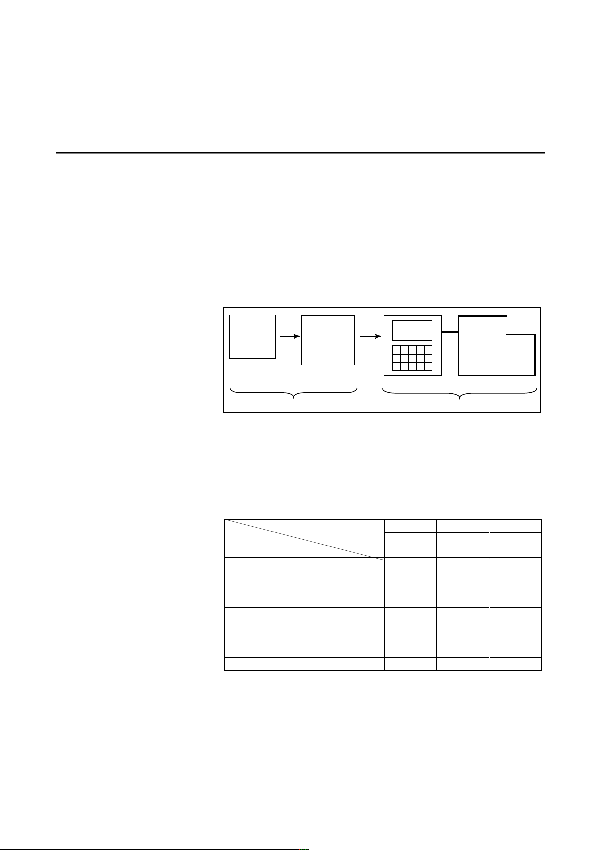
1.1 GENERAL FLOW OF OPERATION OF CNC MACHINE
TOOL
When machining the part using the CNC m achine tool, first prepare the
program, then operate the CNC machine by using the program.
(1) First, prepare the program from a part drawing to operate the CNC
machine tool. How to prepare the program is described in the
OPERATOR’S MANUAL (PROGRAMMING).
(2) The program is to be read into the CNC system. Then, mount the
workpieces and tools on the machine, and operate the tools
according to the programming. Finally, execute the machining
actually. How to operate the CNC system is described in the
OPERATOR’S MANUAL (OPERATION).
Part
drawing
PROGRAMMING
Part
programming
CNC MACHINE TOOL
OPERATION
Before the actual programming, make the machining plan for how to
machine the part.
Machining plan-
1. Determination of workpieces machining range
2. Method of mounting workpieces on the machine tool
3. Machining sequence in every machining process
4. Machining tools and machining
Decide the machining method in every machining process.
Machining process
Machining procedure
1. Machining method
: Rough
Semi
Finish
2. Machining tools
3. Machining conditions
: Feedrate
Cutting depth
4. Tool path
123
Feed
cutting
Side
cutting
Hole
machining
- 5 -
Page 28
1.GENERAL GENERAL B-63324EN/03
Tool
Side cutting
Face cutt ing
Hole machining
Prepare the program of the tool path and machining condition
according to the workpiece figure, for each machining.
- 6 -
Page 29

B-63324EN/03 GENERAL 1.GENERAL
1.2 NOTES ON READING THIS MANUAL
NOTE
1 The function of an CNC mach ine tool system
depends not only on the CNC, but on the
combination of the machine tool, its magnetic
cabinet, the servo system, the CNC, the operator’s
panels, etc. It is too difficult to describe the function,
programming, and operation relating to all
combinations.
This manual generally describes these from the
stand-point of the CNC. So, for details on a particular
CNC machine tool, refer to the manual issued by the
machine tool builder, which should take precedence
over this manual.
2 Headings are placed in the left margin so that the
reader can easily access necessary information.
When locating the necessary information, the reader
can save time by searching though these headings.
3 Machining programs, parameters, variables, etc. are
stored in the CNC unit internal non-volatile memory.
In general, these contents are not lost by the
switching ON/OFF of the power. However, it is
possible that a state can occur where precious data
stored in the non-volatile memory has to be deleted,
because of deletions from a maloperation, or by a
failure restoration.
In order to restore rapidly when this kind of mishap
occurs, it is recommended that you create a copy of
the various kinds of data beforehand.
4 This manual describes as many reasonable
variations in equipment usage as possible. It cannot
address every combination of features, options and
commands that should not be attempted.
If a particular combination of operations is not
described, it should not be attempted.
- 7 -
Page 30

Page 31

II PROGRAMING
Page 32

Page 33

B-63324EN/03 PROGRAMMING 1.GENERAL
1 GENERAL
- 11 -
Page 34

1.GENERAL PROGRAMMING B-63324EN/03
Workpiece
1.1 TOOL MOVEMENT ALONG WORKPIECE PARTS FIGURE-
INTERPOLATION
The tool moves along straight lines and arcs constituting the wo rkpiece
parts figure (See II-4).
Explanation
The function of moving the tool along straight lines and arcs is called
the interpolation.
-Tool movement along a straight line
-Tool movement along an arc
Tool
Program
G01 X_ _ Y_ _ ;
X_ _ ;
Fig.1.1 (a) Tool movement along a straight line
Program
G03X_ _Y_ _R_ _;
Tool
Workpiece
Fig.1.1 (b) Tool movement along an arc
- 12 -
Page 35

B-63324EN/03 PROGRAMMING 1.GENERAL
Symbols of the programmed commands G01, G02, ... are called the
preparatory function and specify the type of interpolation conducted in
the control unit. B
(a) Movement along straight line (b) Movement along arc
G01Y ; G03X Y
X Y ;
bmb
X axis
IInterpolation
Y axis
a) Movement
along straight ine
b) Movement
along arc
Fig.1.1 (c) Interpolation function
R ;
Tool movement
NOTE
Some machines move tables instead of tools but this
manual assumes that tools are moved against
workpieces.
H
- 13 -
Page 36

1.GENERAL PROGRAMMING B-63324EN/03
1.2 FEED-FEED FUNCTION
Movement of the tool at a specified speed for cutting a workpiece is
called the feed.
mm/min
F
Workpiece
Table
Fig.1.2 (a) Feed function
Tool
Feedrates can be specified by using actual numerics.
For example, to feed the tool at a rate of 150 mm/min, specify the
following in the program:
F150.0
The function of deciding the feed rate is called the feed function (See
II-5).
- 14 -
Page 37

B-63324EN/03 PROGRAMMING 1.GENERAL
1.3 PART DRAWING AND TOOL MOVEMENT
1.3.1 Reference Position (Machine-Specific Position)
A CNC machine tool is provided with a fixed position. Normally, tool
change and programming of absolute zero point as described later are
performed at this position. This position is called the reference
position.
Reference position
Tool
Workpiece
Explanations
Table
Fig.1.3.1 (a) Reference position
The tool can be moved to the reference position in two ways:
1. Manual reference position return (See Operation II-3.1)
Reference position return is performed by manual button
operation.
2. Automatic reference position return (See II-6)
In general, manual reference position return is perform ed first after
the power is turned on. In order to move the tool to the reference
position for tool change thereafter, the function of automatic
reference position return is used.
- 15 -
Page 38

1.GENERAL PROGRAMMING B-63324EN/03
Present tool position
Workpiece
Machine tool
1.3.2 Coordinate System on Part Drawing and Coor di nate System
Specified by CNC - Coordinate System
Explanation
-Coordinate system
Z
Part drawing
Y
Fig.1.3.2 (a) Coordinate system
Program
X
Comman
Tool
Z
Y
Z
Y
X
Coordinate system
CNC
X
The following two coordinate systems are specified at different
locations: (See II-7)
1. Coordinate system on part drawing
The coordinate system is written on the part drawing. As the
program data, the coordinate values on this coordinate system are
used.
2. Coordinate system specified by the CNC
The coordinate system is prepared on the actual machine tool
table.
This can be achieved by programming the distance from the
current position of the tool to the zero point of the coordinate
system to be set.
Y
Program
zero point
Fig.1.3.2 (b) Coordinate system specified by the CNC
230
300
Distance to the zero point of a coordinate
system to be set
X
- 16 -
Page 39

B-63324EN/03 PROGRAMMING 1.GENERAL
The positional relation between these two coordinate systems is
determined when a workpiece is set on the table.
Coordinate system on
part drawing established
Coordinate system
specified by the CNC
established on the table
Table
Fig. 1.3.2 (c) Coordinate system specified by CNC and coordinate system
Y
Y
Workpiece
on part drawing
on the workpiece
X
X
The tool moves on the coordinate system specified by the CNC in
accordance with the command program generated with respect to the
coordinate system on the part drawing, and cuts a workpiece into a
shape on the drawing.
Therefore, in order to correctly cut the workpiece as specified on the
drawing, the two coordinate systems must be set at the same position.
-Methods of setting the two coordinate systems in the same position
To set the two coordinate systems at the sam e position, sim ple m ethods
shall be used according to workpiece shape, the number of m achinings.
1 Using a standard plane and point of the workpiece.
Y
Fixed distance
Program
zero point
Bring the tool center to the workpiece standard
point. And set the coordinate system specified
by CNC at this position.
Workpiece’s standard point
Fixed distance
X
- 17 -
Page 40

1.GENERAL PROGRAMMING B-63324EN/03
Program zero point
2 Mounting a workpiece directly against the jig
Jig
Meet the tool center to the reference position.
And set the coordinate system specified by CNC at this position.
(Jig shall be mounted on the predetermined point from the reference
position.)
3 Mounting a workpiece on a pallet, then mounting the workpiece
and pallet on the jig
Pallet
Jig
(Jig and coordinate system shall be specified by the same as 2).
Workpiece
- 18 -
Page 41

B-63324EN/03 PROGRAMMING 1.GENERAL
1.3.3 How to Indicate Command Dimensions for Moving the Tool -
Absolute, Incremental Commands
Explanation
Command for moving the tool can be indicated by absolute command
or incremental command (See II-8.1).
-Absolute command
The tool moves to a point at "the distance from zero point of the
coordinate system" that is to the position of the coordinate values.
Z
X
Command specifying movement f rom
point A to point B
Tool
A
Y
B(10.0,30.0,20.0)
G90X10.0 Y30.0 Z20.0;
Coordinates of point B
- 19 -
Page 42

1.GENERAL PROGRAMMING B-63324EN/03
-Incremental command
Z
Tool
A
X=40.0
Y
Z=-10.0
Y-30.0
X
Command specifying movement from
point A to point B
B
G91 X40.0 Y-30.0 Z-10.0
Distance and direction for movement along each axis
Specify the distance from the previous tool position to the next tool
position.
- 20 -
Page 43

B-63324EN/03 PROGRAMMING 1.GENERAL
1.4 CUTTING SPEED - SPINDLE SPEED FUNCTION
The speed of the tool with respect to the workpiece when the workpiece
is cut is called the cutting speed.
As for the CNC, the cutting speed can be specified by the spindle speed
-1
in min
unit.
Tool
Spindle speed
-1
Nmin
Workpiece
Tool diameter
Dmm
V: Cutting speed
m/min
[N
<When a workpiece should be machined with a tool 100 mm in
diameter at a cutting speed of 80 m/min. >
The spindle speed is approximately 250 min
-1
, which is obtained from
N=1000v/pD. Hence the following command is required:
S250;
Commands related to the spindle speed are called the spindle speed
function (See II-9) .
- 21 -
Page 44

1.GENERAL PROGRAMMING B-63324EN/03
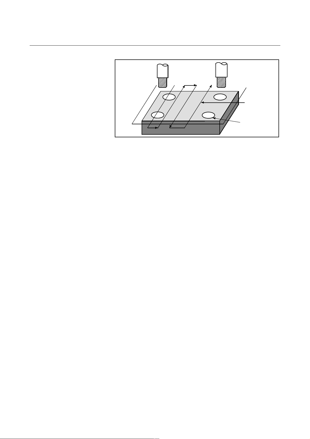
1.5 SELECTION OF TOOL USED FOR VARIOUS MACHINING -
TOOL FUNCTION
When drilling, tapping, boring, milling or the like, is performed, it is
necessary to select a suitable tool.
When a number is assigned to each tool and the number is specified in
the program, the corresponding tool is selected.
Tool number
01
02
ATC magazine
Example
<When No.01 is assigned to a drilling tool>
When the tool is stored at location 01 in the ATC magazine,
T01
the tool can be selected by specifying T01. This is called the tool
function (See II-10).
- 22 -
Page 45

B-63324EN/03 PROGRAMMING 1.GENERAL
1.6 COMMAND FOR MACHINE OPERATIONS -
MISCELLANEOUS FUNCTION
When machining is actually started, it is necessary to rotate the spindle,
and feed coolant. For this purpose, on-off operations of spindle motor
and coolant valve should be controlled.
The function of specifying the on-off operations of the components of
Tool
Coolant
Workpiece
the machine is called the miscellaneous function. In general, the
function is specified by an M code (See II-11).
For example, when M03 is specified, the spindle is rotated clockwise at
the specified spindle speed.
- 23 -
Page 46

1.GENERAL PROGRAMMING B-63324EN/03
1.7 PROGRAM CONFIGURATION
A group of commands given to the CNC for operating the machine is
called the program. By specifying the commands, the tool is moved
along a straight line or an arc, or the spindle motor is turned on and off.
In the program, specify the commands in the sequence of actual tool
movements.
Block
Block
Tool movement sequence
Block
Program
Fig.1.7 (a) Program configuration
Block
Block
A group of commands at each step of the sequence is called the block.
The program consists of a group of blocks for a series of machining.
The number for discriminating each block is called the sequence
number, and the number for discriminating each program is called the
program number (See II-12).
- 24 -
Page 47

B-63324EN/03 PROGRAMMING 1.GENERAL
Dimension word
Explanation
The block and the program have the following configurations.
- Block
1 block
- Program
Nxxxxx Gxx
Sequence
number
Preparatory
function
Xxxx.x Yxxx.x Mxx Sxx Txx ;
Miscellaneous
function
Fig.1.7 (b) Block configuration
Spindle
function
Tool
function
End of block
A block starts with a sequence number to identify the block and ends
with an end-of-block code.
This manual indicates the end-of-block code by ; (LF in the ISO code
and CR in the EIA code).
;
Oxxxx ;
Program number
Block
Block
Block
:
:
:
M30 G
Fig.1.7 (c) Program configuration
:
:
:
End of program
Normally, a program number is specified after the end-of- block (;) code
at the beginning of the program, and a program end code (M02 or M30)
is specified at the end of the program.
- 25 -
Page 48

1.GENERAL PROGRAMMING B-63324EN/03
- Main program and subprogram
When machining of the same pattern appears at many portions of a
program, a program for the pattern is created. This is called the
subprogram.
On the other hand, the original program is called the main program.
When a subprogram execution command appears during execution of
the main program, commands of the subprogram are executed.
When execution of the subprogram is finished, the sequence returns to
the main program.
Main program
:
:
M98P1001
:
:
:
Subprogram #1
O1001
Program for hole #1
M98P1002
:
:
M98P1001
:
:
:
Hole #1
Hole #1
Hole #2
M99
Subprogram #2
O1002
M99
Hole #2
Program for hole #2
- 26 -
Page 49

B-63324EN/03 PROGRAMMING 1.GENERAL
1.8 TOOL FIGURE AND TOOL MOTION BY PROGRAM
Explanation
-Machining using the end of cutter - Tool length compensation function
Usually, several tools are used for machining one workpiece.
The tools have different tool length. It is very troublesome to change
the program in accordance with the tools.
Therefore, the length of each tool used should be measured in advance.
By setting the difference between the length of the standard tool and
the length of each tool in the CNC (Operation : see II-9), machining can
be performed without altering the program even when the tool is
changed. This function is called tool length compensation (See II -14.1).
Standard
H1 H2
tool
Workpiece
H3 H4
-Machining using the side of cutter - Cutter compensation function
Because a cutter has a radius, the center of the cutter path goes around
the workpiece with the cutter radius deviated.
Cutter path using cutter compensation
Workpiece
Machined part
figure
Cutter
If radius of cutters are stored in the CNC (See Operation II-9), the tool
can be moved by cutter radius apart from the machining part figure.
This function is called cutter compensation (See II-14.3, 14.4).
- 27 -
Page 50

1.GENERAL PROGRAMMING B-63324EN/03
1.9 TOOL MOVEMENT RANGE - STROKE
Limit switches are installed at the ends of each axis on the machine to
prevent tools from moving beyond the ends.
The range in which tools can move is called the stroke.
Motor
Limit switch
Specify these distances
Tools cannot enter this area.
The area is specified by data
in memory or a program.
Table
Machine zero point
Besides strokes defined with limit switches, the operator can define an
area which the tool cannot enter using a program or data in memory.
This function is called stroke check (see Operation II-6.3).
- 28 -
Page 51

B-63324EN/03 PROGRAMMING 2.CONROLLED AXES
2 CONTROLLED AXES
- 29 -
Page 52

2.CONROLLED AXES PROGRAMMING B-63324EN/03
2.1 CONTROLLED AXES
Series 15i/150i
Item Standard type Multiple axes type
No. of basic controlled axes 3 axes (2 axes)
Controlled axes expansion
(total)
Basic simultaneously
controlled axes
Simultaneously controlled
axes expansion (total)
Max. 10 ax es (Cs ax is is
2 axes)
Up to Max. control axes (Cs axis is disabled.)
Max. 24 axes
2 axes
- 30 -
Page 53

B-63324EN/03 PROGRAMMING 2.CONROLLED AXES
2.2 AXIS NAME
Names of axes can be optionally selected from X, Y, Z, A, B, C, U, V,
and W. They can be set by parameter No. 1020.
Explanation
- Axis name expansion function
With the optional axis name expansion function, I, J, K, and E can also
be used as axis names.
When I, J, K, and E are used as the names of axes, these addresses have
the following functions and restrictions:
(1) These addresses are addresses for coordinate words.
Example) G17I-K- ; The I-K plane is selected.
(2) The numeric values to be specified must consist of up to 8 digits.
(3) A decimal point can be input.
If a decimal point is omitted, its position is determined according to
the increment system of the axis for that address.
Example) G00 E0.5 I 100 K 100.0;
(4) A signed value can be input.
Example) G01 E-10.5 F100;
Limitation
- Axis name expansion function
- When I, J, K, and E are used as axis names, they cannot be used
for the ordinary purposes listed below.
Address
I,J,K
K G06.2 Not value of NURBS
E
G code or
variable
G02
G03
G41
G42
G76
G87
G22 Stroke limit coordinates Stroke limit
G65
G66
G66.1
G33 Screw pitch (number of
#4108 Macro variable, address E
Center position of an arc Coordinate words
Three- dimensional offset
vector
Canned cycle shift amount Coordinate words
Argument Argument The position of the decimal point is
interpolation
thread for inch screws)
continuous-state information
Normal use
Used for
controlled axes
Use an R command to specify the
for I, J, and K
Coordinate words
for I, J, and K
for I, J, and K
coordinates
K-axis coordinate
word
E-axis coordinate
word
No meaning Custom macro variable #4108 is
center.
Three- dimensional tool compensation is
disabled.
An amount of shift cannot be specified.
A limit position cannot be specified.
determined by the increment system.
NURBS interpolation is disabled.
The number of threads for inch screws
cannot be specified in G33 threading.
unavailable.
Remarks
CAUTION
When this function is used, the second auxiliary
function cannot be used.
- 31 -
Page 54

2.CONROLLED AXES PROGRAMMING B-63324EN/03
2.3 INCREMENT SYSTEM
The increment system uses least input increment (for input) and least
command increment (for output). The least input increment is the least
increment for programming the travel distance. The least command
increment is the least increment for moving the tool on the machine.
Both increments are represented in mm, inches, or deg.
There are five types of increment systems, as shown in Table2.3 (a).
One of the five types can be set for each axis by using bits 0 (ISA), 1
(ISC), 2 (ISD), and 3(ISE) of Parameter No. 1012.
The least input increment is in either metric or inch units. One can be
selected using a G code (G20, G21) or setting parameter.
The least command increment is in either metric or inch units
depending on the machine tool. Set metric or inch in bit 1 (INM) of
parameter No. 1002 in advance.
The metric and inch systems cannot be used together. There are
functions that cannot be used for axes with different unit systems
(circular interpolation, cutter compensation, and so forth).
IS-D and IS-E are optional.
For the increment system, see the manual provided by the machine tool
builder manual.
Name of
increment
system
Table2.3 (a) Increment system
Least input
increment
0.01 mm 0.01 mm 999999.99 mm
0.001 inch 0.001 inch 99999.999 inchIS-A
0.01 deg 0.01 deg 999999.99 deg
0.001 mm 0.001 mm 99999.999 mm
0.0001 inch 0.0001 inch 9999.9999 inchIS-B
0.001 deg 0.001 deg 99999.999 deg
0.0001 mm 0.0001 mm 9999.9999 mm
0.00001 inch 0.00001 inch 999.99999 inchIS-C
0.0001 deg 0.0001 deg 9999.9999 deg
0.00001 mm 0.00001 mm 9999.99999 mm
0.000001 inch 0.000001 inch 999.999999 inchIS-D
0.00001 deg 0.00001 deg 9999.99999 deg
0.000001 mm 0.000001 mm 999.999999 mm
0.0000001 inch 0.0000001 inch 99.9999999 inchIS-E
0.000001 deg 0.000001 deg 999.999999 deg
Least command
increment
Maximum stroke
- 32 -
Page 55

B-63324EN/03 PROGRAMMING 2.CONROLLED AXES
By setting bit 0 (IM0) of parameter No. 1013 for ten-fold input unit,
each increment system is set as shown in Table2.3 (b).
Table2.3 (b)
Name of
increment
system
Least input
increment
0.01 mm 0.001 mm 99999.999 mm
0.001 inch 0.0001 inch 9999.9999 inchIS-B
0.01 deg 0.001 deg 99999.999 deg
0.001 mm 0.0001 mm 9999.9999 mm
0.0001 inch 0.00001 inch 999.99999 inchIS-C
0.001 deg 0.0001 deg 9999.9999 deg
0.0001 mm 0.00001 mm 9999.99999 mm
0.00001 inch 0.000001 inch 999.999999 inchIS-D
0.0001 deg 0.00001 deg 9999.99999 deg
0.00001 mm 0.000001 mm 999.999999 mm
0.000001 inch 0.0000001 inch 99.9999999 inchIS-E
0.00001 deg 0.000001 deg 999.999999 deg
Least command
increment
Maximum stroke
- 33 -
Page 56

2.CONROLLED AXES PROGRAMMING B-63324EN/03
2.4 MAXIMUM STROKE
Maximum stroke = Least command increment × 99999999
(For IS-D and IS-E, 999999999)
See 2.3 Increment System.
Table2.4 (a) Maximum stroke
Increment system Maximum stroke
IS-A
IS-B
IS-C
IS-D
IS-E
Metric machine
system
Inch machine
system
Metric machine
system
Inch machine
system
Metric machine
system
Inch machine
system
Metric machine
system
Inch machine
system
Metric machine
system
Inch machine
system
±999999.99 mm
±999999.99 deg
±99999.999 inch
±999999.99 deg
±99999.999 mm
±99999.999 deg
±9999.9999 inch
±99999.999 deg
±9999.9999 mm
±9999.9999 deg
±999.99999 inch
±9999.9999 deg
±9999.99999 mm
±9999.99999 deg
±999.999999 inch
±9999.99999 deg
±999.999999 mm
±999.999999 deg
±99.9999999 inch
±999.999999 deg
NOTE
1 A command exceeding the maximum stroke cannot
be specified.
2 The actual stroke depends on the machine tool.
- 34 -
Page 57

B-63324EN/03 PROGRAMMING 3.PREPARATORY FUNCTION (G FUNCTION)
3 PREPARATORY FUNCTION (G FUNCTION)
A preparatory function is specified using a numeric value following
address G. This determines the meaning s of the comm ands specified in
the block. G codes are divided into the following two types:
Type Meaning
One-shot G code The G code is effective only in the block in which it is
specified.
Continuous-state
G code
(Example) G01 and G00 are continuous-state G codes.
G01 X_ :
Z_ : G01 is effective in this range.
X_ :
G00 Z_ :
Explanation
1. G codes marked are the initial G codes set when the power is
turned on or when the system is reset.
For G00 and G01, G17, G18, and G19, G43, G44, and G49, G94
and G95, and G90 and G91, the G code status can be selected by
setting bit 0 (G01), bit 1 (G90), bit 2 (G43), bit 3 (G44), bit 4
(G95), and bit 5 (G18) of parameter No. 2401.
For G20 and G21, the system enters the state immediately before
the power is turned off or the reset button is pressed.
2. G codes other than G10 and G11 are one-shot G codes.
3. When a G code not listed in the G code list is specified, or a G
code that has no corresponding option is specified, P/S alarm No.
010 is output.
4. Multiple G codes can be specified in the same block if each G code
belongs to a different group. If mu ltiple G codes that belong to the
same group are specified in the same block, only the last G code
specified is valid.
5. If a G code belonging to group 01 is specified in a canned cycle, the
canned cycle is cancelled. This means that the same state set by
specifying G80 is set. Note that the G codes in group 01 are not
affected by a G code specifying a canned cycle.
6. G codes are indicated by group.
7. The group of G60 is switched according to the setting of the MDL
bit (bit 0 of parameter 7616). (When the MDL bit is set to 0, the 00
group is selected. When the MDL bit is set to 1, the 01 group is
selected.)
The G code is effective until another G code of the
same group is specified.
- 35 -
Page 58

3.PREPARATORY FUNCTION (G FUNCTION) PROGRAMMING B-63324EN/03
Table3 G code list
Code Group Function
G00 Positioning
G01 Linear interpolation
G02 Circular interpolation/Helical interpolation CW
G03 Circular interpolation/Helical interpolation CCW
G02.1 Circular threading B CW
G03.1 Circular threading B CCW
G02.2 Involute interpolation CW
G03.2 Involute interpolation CCW
G02.3 Exponential interpolation CW
G03.3 Exponential interpolation CCW
G02.4 3-dimensional circular interpolation
G03.4 3-dimensional circular interpolation
G06.1 Spline interpolation
G06.2
G04 Dwell
G05.1 Multi-buffer
G07 Hypothetical axis interpolation
G07.1 Cylindrical interpolation
G09 Exact stop
G10 Programmable data input
G10.1 PMC Data setting
G10.6 Tool retract & recover
G10.9 Programmable diameter/radius specification switching
G11
G12.1 Polar coordinate interpolation mode
G13.1
G15 Polar coordinates command cancel
G16
G17 XpYp plane
G18 ZpXp plane
G19
G20 06 Inch input
G21 06 Metric input
G22 Stored stroke check function on
G23
G25 Spindle speed fluctuation detection off
G26
G27 Reference position return check
G28 Return to reference position
G29 Return from reference position
G30 Return to 2nd, 3rd, or 4th reference position
G30.1 Return to floating reference position
G31 Skip function
G31.1 Multistage skip function 1
G31.2 Multistage skip function 2
G31.3 Multistage skip function 3
G31.4 Multistage skip function 4
G31.8 EGB skip function
G31.9
01
NURBS interpolation
00
function
Programmable data input mode cancel
26
Polar coordinate interpolation cancel mode
17
Polar coordinates command
where, Xp:X axis or a parallel axis
02
YpZp plane
04
Stored stroke check function off
25
Spindle speed fluctuation detection on
00
High succession skip function
Yp:Y axis or a parallel axis
Zp:Z axis or a parallel axis
- 36 -
Page 59

B-63324EN/03 PROGRAMMING 3.PREPARATORY FUNCTION (G FUNCTION)
Table3 G code list
Code Group Function
G33 01 Threading
G37 Automatic tool length measurement
G38 Cutter compensation C vector retention
G39
G40
G41
G42 Cutter compensation right
G41.2 3 dimensional cutter compensation left
G42.2 3 dimensional cutter compensation right
G41.3
G40.1 Normal direction control cancel mode
G41.1 Normal direction control left side on
G42.1
G43 Tool length compensation (+ve)
G43.1 Tool length compensation in tool axis direction
G44
G45 Tool offset increase
G46 Tool offset decrease
G47 Tool offset double increase
G48
G49 08 Tool length compensation cancel
G50 Scaling cancel
G51
G50.1 Programmable mirror image cancel
G51.1
G52 Local coordinate system setting
G53
G54 Workpiece coordinate system 1 selection
G54.1 Additional workpiece coordinate system selection
G54.2 Fixture offset selection
G55 Workpiece coordinate system 2 selection
G56 Workpiece coordinate system 3 selection
G57 Workpiece coordinate system 4 selection
G58 Workpiece coordinate system 5 selection
G59
G60 00/01 Unidirectional positioning
G61 Exact stop mode
G62 Automatic corner override
G63 Tapping mode
G64
G65 00 Macro call
G66 Macro modal call A
G66.1 Macro modal call B
G67
G68 Coordinate system rotation
G69
G72.1 Rotation copy
G72.2
00
Cutter compensation C corner rounding
Cutter compensation cancel / Three dimensional
compensation cancel
Cutter compensation left / Three dimensional
compensation
07
Leading edge offset
19
Normal direction control right side on
08
Tool length compensation (-ve)
00
Tool offset double decrease
11
Scaling
18
Programmable mirror image
00
Machine coordinate system selection
14
Workpiece coordinate system 6 selection
15
Cutting mode
12
Macro modal call cancel
16
Coordinate system rotation cancel
00
Linear copy
- 37 -
Page 60

3.PREPARATORY FUNCTION (G FUNCTION) PROGRAMMING B-63324EN/03
Table3 G code list
Code Group Function
G73 Peck drilling cycle
G74 Counter tapping cycle
G76 Fine boring cycle
Canned cycle cancel / external operation function
G80
G81
G80.5
G81.5
G81.1 00 Chopping mode on
G82 Drill cycle, counter boring
G83 Peck drilling cycle
G84 Tapping cycle
G84.2 Rigid tapping cycle
G84.3 Reverse rigid tapping cycle
G85 Boring cycle
G86 Boring cycle
G87 Back boring cycle
G88 Boring cycle
G89
G90 Absolute command
G91
G92
G92.1
G93 Inverse time feed
G94 Feed per minute
G95
G96 Constant surface speed control
G97
G98 Return to initial level in canned cycle
G99
cancel / Electronic gear box synchronous cancel
(Command for hobbing machine or 1 axis)
09
Drill cycle, stop boring /external operation function /
Electronic gear box synchronous start (Command for
hobbing machine or 1 axis)
Electronic gear box synchronous cancel (Command for
2 axes)
Electronic gear box synchronous start (Command for 2
axes)
09
Boring cycle
03
Incremental command
Setting for work coordinate system or clamp at
maximum spindle speed
00
Workpiece coordinate system preset
05
Feed per rotation
13
Constant surface speed control cancel
10
Return to R-point level in canned cycle
- 38 -
Page 61

B-63324EN/01 PROGRAMING 4.INTERPOLATION FUNCTIONS
4 INTERPOLATION FUNCTIONS
- 39 -
Page 62

4.INTERPOLATION FUNCTIONS PROGRAMING B-63324EN/01
4.1 POSITIONING (G00)
The G00 command mov es a tool to the position in the workpiece sy stem
specified with an absolute or an incremental com m and at a rapid trav erse
rate.
In the absolute command, coordinate value of the end point is
programmed.
In the incremental comm and the distance the tool m oves is prog ram m ed.
Format
G00 IP_ ;
IP_ : For an absolute command, the coordinates of an end
position, and for an incremental com m nad, the
distance the tool moves.
Explanation
Either of the following tool paths can be selected according to bit 1 of
parameter LRP No. 1401.
- Nonlinear interpolation positioning
The tool is positioned with the rapid traverse rate for each axis
separately. The tool path is normally straight.
- Linear interpolation positioning
The tool path is the same as in linear interpolation (G01). The tool is
positioned within the shortest possible time at a speed that is not m ore
than the rapid traverse rate for each axis.
Linear interpolation positioning
End position
Non linear interpolation positioning
Fig.4.1 (a) Tool path
The rapid traverse rate in G00 command is set to the parameter No. 1420
for each axis independently by the machine tool builder. In the
posiitoning mode actuated by G00, the tool is accelerated to a
predetermined speed at the start of a block and is decelerated at the end
of a block. Execution proceeds to the next block after confirming the
in-position.
"In-position " means that the feed motor is within the specified range.
Start position
- 40 -
Page 63

B-63324EN/01 PROGRAMING 4.INTERPOLATION FUNCTIONS
This range is determined by the machine tool builder by setting to
parameter (No. 1827).
In-position check for each block can be disabled by setting bit 0 (C I P) of
parameter No.1000 accordingly.
Limitation
(1) The rapid traverse rate cannot be specified in the address F.
(2) Even if linear interpolation positioning is specified, nonlinear
interpolation positioning is used in the following cases. Therefore, be
careful to ensure that the tool does not foul the workpiece.
- G28 specifying positioning between the reference and
intermediate positions.
-G53
- 41 -
Page 64

4.INTERPOLATION FUNCTIONS PROGRAMING B-63324EN/01
4.2 SINGLE DIRECTION POSITIONING (G60)
For accurate positioning without play of the machine (backlash), final
positioning from one direction is available.
Overrun
Start position
Start position
Format
Explanation
End position
Fig.4.2 (a) Direction positioning process
Temporary stop
G60 IP_ ;
IP_ : For an absolute command, the coordinates of an end
position, and for an incremental com m nad, the
distance the tool moves.
An overrun and a positioning direction are set by the parameter (No.
6820).
Even when a commanded positioning direction coincides with that set by
the parameter, the tool stops once before the end point.
G60, which is an one-shot G-code, can be used as a modal G-code in
group 01 by setting 1 to the parameter (No. 7616 bit 0 G60).
This setting can eliminate specifying a G60 command for every block.
Other specifications are the same as those for an one-shot G60 command.
When an one-shot G code is specified in the single direction positioning
mode, the one-shot G command is effective like G codes in group 01.
- 42 -
Page 65

B-63324EN/01 PROGRAMING 4.INTERPOLATION FUNCTIONS
(Example)
When one-shot G60 commands When modal G60 command
are used. is used.
::
::
G90; G90 G60; Single direction
G60 X0 Y0; X0 Y0; positioning mode start
G60 X100; Single direction X100; Single direction
G60 Y100; positioning Y100; positioning
G04 X10; G04 X10;
G00 X0 Y0; G00 X0 Y0; Single direction
positioning mode
cancel
Limitation
- During canned cycle for drilling(G81to G89, G73, G74, G76), no
single direction positioning is effected in drilling axis.
- No single direction positioning is effected in an axis for which no
overrun has been set by the parameter.
- When the move distance 0 is commanded, the single direction
positioning is not performed.
- The direction set to the parameter is not effected by mirror image.
- The single direction positioning does not apply to the shift motion
in the canned cycles of G76 and G87.
- The single Direction Positioning is always non linear interpolation
type positioning.
- The parameter FPI (No. 1000#3) can be used to determine whether
the in-position check is to be done or not at the tem porary stop point
- 43 -
Page 66

4.INTERPOLATION FUNCTIONS PROGRAMING B-63324EN/01
α
γ
ζ
4.3 LINEAR INTERPOLATION (G01)
Tools can move along a line
Format
G01 IP_ F_ ;
IP_ :For an absolute command, the coordinates of an end
point , and for an incremental commnad, the distance
the tool moves.
F_ :Speed of tool feed (Feedrate)
Explanation
A tools move along a line to the specified position at the feedrate
specified in F. The feedrate specified in F is effective until a new value is
specified. It need not be specified for each block.
- The feedrate commanded by the F code is measured along the tool
path. If the F code is not commanded, the feedrate is regarded as
zero.
- The feedrate of each axis direction is as follows.
G01 αα ββ γγ ζζ Ff ;
Feed rate of α axis direction : Fα =
Feed rate of β axis direction : Fβ =
Feed rate of γ axis direction : Fγ=
Feed rate of ζ axis direction : Fζ =
L=
- The feed rate of the rotary axis is commanded in the unit of deg/min
(the unit is decimal point position).
- When the straight line axis
axis
β (such as A, B, or C) are linearly interpolated, the feed rate is
that in which the tangential feed rate in the α and
coordinate system is commanded by F(mm/min).
β-axis feedrate is obtained ; at first, the time required for
distribution is calculated by using the above formula, then the
axis feedrate unit is changed to deg 1min.
2222
ζγβα
+++
¿(such as X, Y, or Z) and the rotating
× f
L
β
× f
L
× f
L
× f
L
β Cartesian
β-
- 44 -
Page 67

B-63324EN/01 PROGRAMING 4.INTERPOLATION FUNCTIONS
(Example)
G91 G01 X20.0 C40.0 F300.0 G
This changes the unit of the C axis from 40.0 deg to
40mm with metric input.
The time required for distribution is calculated as
follows:
22
4020
300
+
≅
min14907.0
The feed rate for the C axis is
deg40
≅
min14907.0
- In simultaneous 3 axes control, the feed rate is calculated the same
way as in 2 axes control.
min/268.3deg
Example
- Linear interpolation
(G91) G01X200.0Y100.0F200.0;
- Feedrate for the rotation axis
Y axis
100.0
0(Start position)
Fig.4.3 (a) Linear interpolation
G91G01C-90.0 G300.0 ;Feed rate of 300deg/min
90°
(End position)
200.0
(Start point)
X axis
(End point)
Feedrate is 300 deg/min
Fig.4.3 (b) Feedrate for the rotation axis
- 45 -
Page 68

4.INTERPOLATION FUNCTIONS PROGRAMING B-63324EN/01
4.4 CIRCULAR INTERPOLATION (G02,G03)
The command below will move a tool along a circular arc.
Format
Arc in the XpYp plane
G02 I_ J_
G17 Xp_ Yp_ F_ ;
G03 R_
Arc in the ZpXp plane
G02 K_ I_
G18 Zp_ Xp_ F_ ;
G03 R_
Arc in the YpZp plane
G02 J_ K_
G19 Yp_ Zp_ F_ ;
G03 R_
Description of the Command Format
Command Description
G17 Specification of arc on XpYp plane
G18 Specification of arc on ZpXp plane
G19 Specification of arc on YpZp plane
G02 Circular Interpolation Clockwise direction (CW)
G03 Circular Interpolation Counterclockwise direction (CCW)
Xp_
Yp_
Zp_
I_
J_
K_
R_ Arc radius (with sign)
F_ Feedrate along the arc
Command values of X axis or its parallel axis
(set by parameter No. 1022)
Command values of Y axis or its parallel axis
(set by parameter No. 1022)
Command values of Z axis or its parallel axis
(set by parameter No. 1022)
Xp axis distance from the start point to the center of an arc
with sign (with sign)
Yp axis distance from the start point to the center of an arc
with sign (with sign)
Zp axis distance from the start point to the center of an arc
with sign (with sign)
- 46 -
Page 69

B-63324EN/01 PROGRAMING 4.INTERPOLATION FUNCTIONS
Xp
Explanation
- Direction of the circular interpolation
"Clockwise"(G02) and "counterclockwise"(G03) on the XpYp plane
(ZpXp plane or YpZp plane) are defined when the XpYp plane is v iewed
in the positive-to-negative direction of the Zp axis (Yp axis or Xp axis,
respectively) in the Cartesian coordinate system. See the figure below.
Yp
G03
G02
G17
Fig.4.4 (a) Direction of the circular interpolation
- Distance moved on an arc
The end point of an arc is specified by address Xp, Yp or Zp, and is
expressed as an absolute or incremental value according to G90 or G91.
For the incremental value, the distance of the end point which is viewed
from the start point of the arc is specified.
- Distance from the start point to the center of arc
The arc center is specified by addresses I, J, and K for the Xp, Yp, and Zp
axes, respectively. The numerical value following I, J, or K, however, is
a vector component in which the arc center is seen from the start point,
and is always specified as an incremental value irrespective of G90 and
G91, as shown below.
I, J, and K must be signed according to the direction.
Xp
G02
G18
G03
Zp
G02
G19
G03
YpZp
Z
End point (z,x)
k
Start point
i
Z
Y
Center
End point (y,z)
Start point
j
k
End point (x,y)
Y
X
i
Center
Fig.4.4 (b) Distance from the start point to the center of arc
X
Start point
j
Center
I0,J0, and K0 can be omitted.
When Xp, Yp , and Zp are omitted (the end point is the same as the start
point) and the center is specified with I, J, and K, a 360deg. arc (circle) is
specified.
G02 I_ ; @Command for a circle
If the difference between the radius at the start point and that at the end
point exceeds the permitted value in a parameter (No.2410), an P/S alarm
(No.191) occurs.
- 47 -
Page 70

4.INTERPOLATION FUNCTIONS PROGRAMING B-63324EN/01
- Arc radius
The distance between an arc and the center of a circle that contains the
arc can be specified using the radius, R, of the circle instead of I, J, and
K.
In this case, one arc is less than 180deg., and the other is more than
180deg. are considered. When an arc exceeding 180deg. is comm anded,
the radius must be specified with a negative value. I f Xp, Yp, and Zp are
all omitted, if the end point is located at the same position as the start
point and when R is used, an arc of 0deg. is programmed G02R ; (The
cutter does not move.)
(Example)
For arc (1) (less than 180°)
G91 G02 X60.0 Y20.0 R50.0 F300.0 :
For arc (2) (greater than 180°)
G91 G02 X60.0 Y20.0 R-50.0 F300.0 :
(2)
r =50mm
- Feedrate
End point
(1)
Start point
Y
Fig.4.4 (c) Arc radius
r =50mm
X
The feedrate in circular interpolation is equal to the feed rate specified by
the F code, and the feedrate along the arc (the tangential feedrate of the
arc) is controlled to be the specified feedrate.
- 48 -
Page 71

B-63324EN/01 PROGRAMING 4.INTERPOLATION FUNCTIONS
γ−γ
- Cases where a spiral results
When an end point does not lie on the arc, a spiral results, as shown
below.
End point
γe
)t(s)e(
Start point
θ(t)
γ(t)
+γ=γ
˘
s(t)
radius
Start point
γs
γe
The arc radius changes linearly with the center angle θ(t). Spiral
interpolation is performed using a circular command that specifies one
arc radius for the start point and another arc radius for the end point. To
use spiral interpolation, set a large value in parameter No. 2410, used to
specify the limit on the arc radius error.
Limitation
- Simultaneous specification of I, J, K, and R
If I, J, K, and R addresses are specified simultaneously, the arc specified
by address R takes precedence and the other are ignored.
End point
θ
Center
Center θ
γs
Fig.4.4 (d) Case Where a Spiral Is Produced
- Commandment of an axis not comprising the specified plane
If an axis not comprising the specified plane is commanded, an alarm is
displayed.
For example, if axis U is specified as a parallel axis to X axis when plane
XY is specified, an P/S alarm (No.0186)is displayed.
- Specifying a semicircle by R
If an arc has a central angle of nearly 180°, an error may occur when the
position of the center is calculated. To avoid this error, specify the
semicircle by R using two arcs having a central angle of nearly 90° or
specify its center position directly by I, J, and K.
- 49 -
Page 72

4.INTERPOLATION FUNCTIONS PROGRAMING B-63324EN/01
Example
Y axis
100
50R
60
40
60R
0
Fig.4.4 (e) Sample program
90
120
140
The above tool path can be programmed as follows ;
(1) In absolute programming
G92X200.0 Y40.0 Z0 ;
G90 G03 X140.0 Y100.0R60.0 F300.;
G02 X120.0 Y60.0R50.0 ;
or
G92X200.0 Y40.0Z0 ;
G90 G03 X140.0 Y100.0I-60.0 F300.;
G02 X120.0 Y60.0I-50.0 ;
(2) In incremental programming
G91 G03 X-60.0 Y60.0 R60.0 F300.;
G02 X-20.0 Y-40.0 R50.0 ;
or
G91 G03 X-60.0 Y60.0 I-60.0 F300. ;
G02 X-20.0 Y-40.0 I-50.0 ;
200
X axis
- 50 -
Page 73

B-63324EN/01 PROGRAMING 4.INTERPOLATION FUNCTIONS
4.5 HELICAL INTERPOLATION (G02,G03)
Helical interpolation which moved helically is enabled by specifying up
to two other axes which move synchronously with the circular
interpolation by circular commands.
Format
Synchronously with arc of XpYp plane
G02 I_ J_
G17 Xp_ Yp_
G03 R_
Synchronously with arc of ZpXp plane
G02 K_ I_
G18 Zp_ Xp_
G03 R_
Synchronously with arc of YpZp plane
G02 J_ K_
G19 Yp_ Zp_
G03 R_
α_ (β_) F_ ;
α_ (β_) F_ ;
α_ (β_) F_ ;
Explanation
α, β
: Any one axis where circular interpolation is not
applied.
Up to two other axes can be specified.
The basic command method involves simply adding a move command
for one or two axes, other than circular interpolation axes, to a circular
interpolation command (see II-4.4).
As the feedrate, either a feedrate tangent to an arc or a tangential feedrate
determined by also considering movement along the linear axes can be
specified. The feedrate to be specified can be selected by setting bit 2
(HTG) of parameter No. 1401. If HTG is set to 0, a feedrate along an arc
is specified by an F command. Therefore, the feedrate on a linear axis is
as follows:
F ×
axislinearofLength
arccircularofLength
Determine the feedrate so that the linear axis feedrate does not exceed
any of the limit values.
- 51 -
Page 74

4.INTERPOLATION FUNCTIONS PROGRAMING B-63324EN/01
Z
Tool path
X
The feedrate along the circumference of two
circular interpolated axes is the specified feedrate.
Fig.4.5 (a) Feedrate When Parameter HTG = 0
Y
When bit 2 (HTG) of parameter No. 1401 is set to 1, the speed com m and
specifies the feedrate along the actual tool path, including movement
along the linear axis.
In this case, the feedrate along the arc on the plane is:
F+×
arccircularofLength
22
)()( axislinearofLengtharccircularofLength
The feedrate along the linear axis is:
F+×
Z
axislinearofLength
22
)()( axislinearofLengtharccircularofLength
Limitation
Tool path
X
The speed command specifies the
feedrate along the tool path.
Fig.4.5 (b) Feedrate When Parameter HTG = 1
Y
- Cutter compensation is applied only for a circular arc.
- Tool offset and tool length compensation cannot be used in a block
in which a helical cutting is commanded.
- 52 -
Page 75

B-63324EN/01 PROGRAMING 4.INTERPOLATION FUNCTIONS
4.6 HELICAL INTERPOLATION B (G02,G03)
Helical interpolation B allows the tool to move in helically. This can be
done by specifying the circular interpolation command together with up
to four axes.
Format
Synchronously with arc of XpYp plane
G02 I_ J_
G17 Xp_ Yp_
G03 R_
Synchronously with arc of ZpXp plane
G02 K_ I_
G18 Zp_ Xp_
G03 R_
Synchronously with arc of YpZp plane
G02 J_ K_
G19 Yp_ Zp_
G03 R_
¿_
¿_
¿_
_ γ_ δ_ F_ ;
_ γ_ δ_ F_ ;
_ γ_ δ_ F_ ;
Explanation
Limitation
The command format for helical interpolation B consists of the
command format for normal helical interpolation and move commands
for two axes. As with normal helical interpolation, the feedrate of helical
interpolation B is controlled so that the feedrate of circular interpolation
can achieve the specified feedrate.(See II-4.6)
Bit 2 (HTG) of parameter No. 1401 can be used to specify whether the
speed command specifies the feedrate along the tangential line of the arc
on the plane, or the feedrate along the tangential line of the actual tool
path, including movement along the linear axis.
- Cutter compensation is applied only for a circular arc.
- Tool offset and tool length compensation cannot be used in a block
in which a helical cutting is commanded.
- 53 -
Page 76

4.INTERPOLATION FUNCTIONS PROGRAMING B-63324EN/01
π
4.7 HYPOTHETICAL AXIS INTERPOLATION (G07)
In helical interpolation, when pulses are distributed with one of the
circular interpolation axes set to a hypothetical axis, sine interpolation is
enabled.
When one of the circular interpolation axes is set to a hypothetical axis,
pulse distribution causes the speed of movement along the remaining
axis to change sinusoidally. If the major axis for threading (the axis
along which the machine travels the longest distance) is set to a
hypothetical axis, threading with a fractional lead is enabled. The axis to
be set as the hypothetical axis is specified with G07.
Format
G07 ¿0; Hypothetical axis setting
G07 ¿1; Hypothetical axis cancel
Where, ¿ is any one of the addresses of the contr olled axes.
Explanation
- Sine interpolation
The ¿ axis is regarded as a hypothetical axis for the period of time from
the G07 ¿ 0 command until the G07 ¿ 1 command appears.
Suppose sine interpolation is performed for one cycle in the YZ plane.
The hypothetical axis is then the X axis.
2{Y2
X
= r2 (r is the radius of an arc. j
Y = rSIN (
Y
r
0
2
Z) (l is the distance traveled along the Z-axis in
l
one cycle. j
l
4
l
Fig.4.7 (a) Sine interpolation
Z
- Interlock, stroke limit, and external deceleration
Interlock, stroke limit, and external deceleration can also apply to the
hypothetical axis.
- 54 -
Page 77

B-63324EN/01 PROGRAMING 4.INTERPOLATION FUNCTIONS
- Handle interrupt
Specify hypothetical axis interpolation only in the incremental mode.
Limitation
- Manual operation
The hypothetical axis can be used only in automatic operation. In
manual operation, it is not used, and movement takes place.
- Move command
Specify hypothetical axis interpolation only in the incremental mode.
- Coordinate rotation
Hypothetical axis interpolation does not support coordinate rotation.
Example
- Sine interpolation
Y
10.0
0
Fig.4.7 (b) Sine interpolation isample j
N001 G07 X0 ;
N002 G91 G17 G03 X-20.0 Y0.0 I-10.0 Z20.0 F100 ;
N003 G01 X10.0 ;
N004 G07 X1 ;
From the N002 to N003 blocks, the X-axis is set to a hypothetical axis.
The N002 block specifies helical cutting in which the Z - axis is the linear
axis. Since no movement takes place along the X axis, movement along
the Y-axis is performed while performing sine interpolation along the
Z-axis.
In the N003 block, there is no movement along the X-axis, and so the
machine dwells until interpolation terminates.
- Changing the feedrate to form a sine curve
(Sample program j
G07Z0 ; The Z-axis is set to a hypothetical axis.
G02X0Z0I10.0F4. ; The feedrate on the X-axis changes
G07Z1 ; The use of the Z-axis as a hypothetical axis is
Z
20.0
sinusoidally.
canceled.
- 55 -
Page 78

4.INTERPOLATION FUNCTIONS PROGRAMING B-63324EN/01
F
4.0
Xt
Fig.4.7 (c) Changing the feedrate to from a sine curve isample j
- 56 -
Page 79

B-63324EN/01 PROGRAMING 4.INTERPOLATION FUNCTIONS
4.8 POLAR COORDINATE INTERPOLATION (G12.1,G13.1)
Polar coordinate interpolation is a function that exercises contour control
in converting a command programmed in a Cartesian coordinate system
to the movement of a linear axis (m ov em ent of a tool) and the mo vem ent
of a rotary axis (rotation of a workpiece). This function is useful for
grinding a cam shaft.
Format
G12.1; Starts polar coordinate interpolation mode
(enables polar coordinate interpolation)
Specify linear or circular interpolation using
coordinates in a Cartesian coordinate system
consisting of a linear axis and rotary axis
(virtual axis).
G13.1 Polar coordinate interpolation mode is
cancelled (for not performing polar
coordinate interpolation)
Specify G12.1 and G13.1 in Separate Blocks.
Explanation
- Polar coordinate interpolation plane
G12.1 starts the polar coordinate interpolation mode and selects a polar
coordinate interpolation plane (Fig.4.8 (a)). Polar coordinate
interpolation is performed on this plane.
Origin of the local coordinate system (G52 command)
(Or origin of the workpiece coordinate system)
Rotary axis (virtual axis)
(unit : mm or inc h)
Linear axis
(unit : mm or inc h)
Fig.4.8 (a) Polar coordinate interpolation plane.
When the power is turned on or the system is reset, polar coordinate
interpolation is canceled (G13.1).
The linear and rotation axes for polar coordinate interpolation must be
set in parameters (No. 1032 and 1033) beforehand.
- 57 -
Page 80

4.INTERPOLATION FUNCTIONS PROGRAMMING B-63324EN/03
CAUTION
The plane used before G12.1 is specified (plane
selected by G17, G18, or G19) is canceled. It is
restored when G13.1 (canceling polar coordinate
interpolation) is specified.
When the system is reset, polar coordinate
interpolation is canceled and the plane specified by
G17, G18, or G19 is used.
- Distance moved and feedrate for polar coordinate interpolation
The unit for coordinates on th e hypothetical axis is the sam e as the unit for the linear axis
(mm/inch)
In the polar coordinate interpolation mode, program commands are
specified with Cartesian coordinates on the polar coordinate
interpolation plane. The axis address for the rotation axis is used as the
axis address for the second axis (virtual axis) in the plane. Whether a
diameter or radius is specified for the first axis in the plane is the same
as for the rotation axis regardless of the specification for the first axis in
the plane.
The virtual axis is at coordinate 0 immediately after G12.1 is specified.
Polar interpolation is started assuming the angle of 0 for the position of
the tool when G12.1 is specified.
The unit for the feedrate is mm/min or inch/min
Specify the feedrate as a speed (relative speed between the workpiece
and tool) tangential to the polar coordinate interpolation plane
(Cartesian coordinate system) using F.
- G codes which can be specified in the polar coordinate interpolation mode
G01.......................Linear interpolation
G02, G03.............. Circular interpolation
G04,G09............... Dwell, Exact stop
G40, G41, G42.....Cutter compensation (Polar coordinate
interpolation is applied to the path after cutter
compensation.)
G65, G66, G67.....Custom macro command
G90, G91.............. Absolute command, incremental command
G94, G95.............. Feed per minute, feed per revolution
- Circular interpolation in the polar coordinate plane
The addresses for specifying the radius of an arc for circular
interpolation (G02 or G03) in the polar coordinate interpolation plane
depend on the first axis in the plane (linear axis).
- I and J in the Xp-Yp plane when the linear axis is the X-axis or an
axis parallel to the X-axis.
- J and K in the Yp-Zp plane when the linear axis is the Y-axis or an
axis parallel to the Y-axis.
- K and I in the Zp-Xp plane when the linear axis is the Z - axis or an
axis parallel to the Z-axis.
The radius of an arc can be specified also with an R command.
- 58 -
Page 81

B-63324EN/03 PROGRAMMING 4.INTERPOLATION FUNCTIONS
- Movement along axes not in the polar coordinate interpolation plane in the polar
coordinate interpolation mode
The tool moves along such axes normally, independent of polar
coordinate interpolation.
- Current position display in the polar coordinate interpolation mode
Actual coordinates are displayed. However, the remaining distance to
move in a block is displayed based on the coordinates in the polar
coordinate interpolation plane (Cartesian coordinates).
Limitation
- Coordinate system for the polar coordinate interpolation
Before G12.1 is specified, a local coordinate system (or workpiece
coordinate system) where the center of the rotary axis is the origin of
the coordinate system must be set. In the G12.1 mode, the coordinate
system must not be chang ed (G92, G52, G53, relativ e coordinate reset,
G54 through G59, etc.).
- Tool offset command
The polar coordinate interpolation mode cannot be started or
terminated (G12.1 or G13.1) in the tool offset mode (G41 or G42).
G12.1 or G13.1 must be specified in the tool offset canceled mode
(G40).
- Tool length offset command
Tool length offset must be specified in the polar coordinate
interpolation cancel mode before G12.1 is specified. It cannot be
specified in the polar coordinate interpolation mode. Furthermore, no
offset values can be changed in the polar coordinate interpolation
mode.
- Tool offset command
A tool offset must be specified before the G12.1 m ode is set. No offset
can be changed in the G12.1 mode.
- Program restart
For a block in the G12.1 mode, the program cannot be restarted.
- Cutting feedrate for the rotation axis
Polar coordinate interpolation converts the tool movement for a figure
programmed in a Cartesian coordinate system to the tool movement in
the rotation axis (C-axis) and the linear axis (X-axis). When the tool
moves closer to the center of the workpiece, the C-axis component of
the feedrate becomes larger and may exceed the maximum cutting
feedrate for the C-axis (set in parameter (No. 1422)), causing an alarm
(see the warning below). To prevent the C-axis component from
exceeding the maximum cutting feedrate for the C-axis, reduce the
feedrate specified with address F or create a program so that the tool
(center of the tool when cutter compensation is applied) does not move
close to the center of the workpiece.
- 59 -
Page 82

4.INTERPOLATION FUNCTIONS PROGRAMMING B-63324EN/03
π
WARNRING
1. Consider lines L1, L2, and L3. ∆X is the distance the
tool moves per time unit at the feedrate speci fied with
address F in the Cartesian coordinate system. As
the tool moves from L1 to L2 to L3, the angle at whic h
the tool moves per time unit corresponding to ∆X in
the Cartesian coordinate system increases from θ1
to θ2 to θ3.
In other words, the C- axi s component of the feedrate
becomes larger as the tool moves closer to the
center of the workpiece. The C component of the
feedrate may exceed the maximum cutting feedrate
for the C-axis because the tool movement in the
Cartesian coordinate system has been converted to
the tool movement for the C-axis and the X-axis.
∆X
θ1
θ2
θ3
L1
L2
L3
L : Distance (in mm) between the tool center and
workpiece center when the tool center is the
nearest to the workpiece center
R : Maximum cutting feedrate (deg /min) of the C ax is
Then, a speed specifiable with address F in polar
coordinate interpolation can be given by the formula
below.
Specify a speed allowed by the formula. The
formula provides a theoretical value; in practice, a
value slightly smaller than a theoretical value may
need to be used due to a calculation error.
F<L×R×
imm/min j
180
The speed can be controlled so as to prevent the
issue of alarm OT512 (excessive speed). See II-
5.5..2 for details.
- 60 -
Page 83

B-63324EN/03 PROGRAMMING 4.INTERPOLATION FUNCTIONS
WARNRING
3. The following functions cannot be used for the
rotation axis for polar coordinate i nter pol ation. U si ng
any of these functions results in abnormal operation.
- Roll-over function
- Multiple-rotary axis control
- Index table indexing function
- 61 -
Page 84

4.INTERPOLATION FUNCTIONS PROGRAMMING B-63324EN/03
Example
Example of Polar Coordinate Interpolation Program Based on X Axis(Linear Axis) and C Axis (Rotary
Axis)
C’(hypothetical axis)
C axis
N204
N205
N206
Fig.4.8 (b) Polar Coordinate Interpolation Program Based on X Axis(Linear Axis) and C Axis (Rotary Axis)
N203
N202
N208
N207
Path after cutter compensation
Program path
N201
N200
Tool
Z axis
X axis
O001;
:
N010 T0101
:
N0100 G90 G00 X60.0 C0 Z_ ; Positioning to start position
N0200 G12.1; Start of polar coordinate
N0201 G42 G01 X20.0F_ ;
N0202 C10.0;
N0203 G03 X10.0 C20.0 R10.0;
N0204 G01 X-20.0;
N0205 C-10.0; Geometry program
N0206 G03 X-10.0-20.0 I10.0 J0; (program based on Cartesian
N0207 G01 X20.0; coordinates on X-C’ plane)
N0208 C0;
N0209 G40 X60.0;
N0210 G13.1: Cancellation of polar coordinate interpolation
N0300 Z_ :
N0400 X_ C_ ;
:
N0900M30;
- 62 -
Page 85

B-63324EN/03 PROGRAMMING 4.INTERPOLATION FUNCIONS
4.9 CYLINDRICAL INTERPOLATION (G07.1)
The amount of travel of a rotary axis specified by an angle is once
internally converted to a distance of a linear axis along the outer
surface so that linear interpolation or circular interpolation can be
performed with another axis. After interpolation, such a distance is
converted back to the amount of travel of the rotary axis.
The cylindrical interpolation function allows the side of a cylinder to
be developed for programming. So programs such as a program for
cylindrical cam grooving can be created very easily.
Format
G07.1 IPr ; Starts the cylindrical interpolation
: mode
: (enables cylindrical interpolation).
G07.1 IP0 ; The cylindrical interpolation mode is
cancelled.
IP : An address for the rotation axis
r : The radius of t he cylinder
Specify G07.1 IPr ; and G07.1 IP0; in separ ate blocks.
G107 can be used instead of G07.1.
Explanation
- Plane selection (G17,G18,G19)
- Feedrate
Use parameter (No. 1022) to specify whether the rotation axis is the X-,
Y-, or Z-axis, or an axis parallel to one of these axes. Specify the G
code to select a plane for which the rotation axis is the specified linear
axis.
For example, when the rotation axis is an axis parallel to the X-axis,
G17 must specify an Xp-Yp plane, which is a plane defined by the
rotation axis and the Y-axis or an axis parallel to the Y-axis.
Only one rotation axis can be set for cylindrical interpolation.
A feedrate specified in the cylindrical interpolation mode is a speed on
the developed cylindrical surface.
- 63 -
Page 86

4.INTERPOLATION FUNCIONS PROGRAMMING B-63324EN/03
- Circular interpolation (G02,G03)
In the cylindrical interpolation mode, circular interpolation is possible
with the rotation axis and another linear axis. Radius R is used in
commands in the same way as described in II-4.4.
The unit for a radius is not degrees but millimeters (for metric input) or
inches (for inch input).
@Example jCircular interpolation between the Z axis and C axis
For the C axis of parameter (No.1022), 5 (axis parallel with the X
axis) is to be set. In this case, the command for circular
interpolation is
G18 Z_ C_ ;
G02(G03) Z_ C_ R_ ;
For the C axis of parameter (No.1022), 6 (axis parallel with the Y
axis) may be specified instead. In this case, however, the
command for circular interpolation is
G19 C_ Z_ ;
G02(G03) Z_ C_ R_ ;
- Cylindrical interpolation accuracy
In the cylindrical interpolation mode, the amount of travel of a rotary
axis specified by an angle is once internally converted to a distance of a
linear axis on the outer surface so that linear interpolation or circular
interpolation can be performed with another axis. After interpolation,
such a distance is converted back to an angle. For this conversion, the
amount of travel is rounded to a least input increment.
So when the radius of a cylinder is small, the actual amount of travel
can differ from a specified amount of travel. Note, however, that such
an error is not accumulative.
If manual operation is performed in the cylindrical interpolation mode
with manual absolute on, an error can occur for the reason described
above.
The actual MOTION REV 2×2π×R
Amount = ------------------× Specified value× ----------------of travel 2×2π×R MOTION REV
MOTION REV:The amount of travel per rotation of the rotation axis
(Setting value of parameter No. 1260)
R:Workpiece radius
:Rounded to the least input increment
- 64 -
Page 87

B-63324EN/03 PROGRAMMING 4.INTERPOLATION FUNCIONS
Limitation
- Arc radius specification in the cylindrical interpolation mode
In the cylindrical interpolation mode, an arc radius cannot be specified
with word address I, J, or K.
- Cutter compensation
To perform cutter compensation, specify G41, G42, and G40 in
cylindrical interpolation mode. Note that when cylindrical
interpolation mode is set during cutter compensation, correct
compensation cannot be applied.
- Positioning
In the cylindrical interpolation m ode, positioning operations (including
those that produce rapid traverse cycles such as G28, G53, G73, G74,
G76, G80 through G89) cannot be specified. Before positioning can be
specified, the cylindrical interpolation mode must be cancelled.
Cylindrical interpolation (G07.1) cannot be performed in the
positioning mode (G00).
- Coordinate system setting
In the cylindrical interpolation mode, a workpiece coordinate system
(G92, G54 through G59) or local coordinate system (G52) cannot be
specified.
- Cylindrical interpolation mode setting
In the cylindrical interpolation mode, the cylindrical interpolation
mode cannot be reset. The cylindrical interpolation mode must be
cancelled before the cylindrical interpolation mode can be reset.
- Rotation axis
Only one rotation axis can be set in cylindrical interpolation. With the
G97.1 command, no more than one rotation axis can be specified.
- Parallel axis
The rotation axis for cylindrical interpolation is not a parallel axis.
- Tool offset
A tool offset must be specified before the cylindrical interpolation
mode is set. No offset can be changed in the cylindrical interpolation
mode.
- Index table indexing function
Cylindrical interpolation cannot be specified when the index table
index function is being used.
- Rotation axis rollover function
If the rotation axis for which the rollover function is used is specified as
the rotation axis used with cylindrical interpolation, the rollover
function is disabled in cylindrical interpolation mode.
When cylindrical interpolation mode is cancelled, the rollover function
is automatically enabled.
- 65 -
Page 88

4.INTERPOLATION FUNCIONS PROGRAMMING B-63324EN/03
- Multiple-rotary axis control function
If the rotation axis for which the multiple-rotary-axis control function
is used is specified as the rotation axis used with cylindrical
interpolation, the multiple-rotary axis control function is disabled in
cylindrical interpolation mode.
When cylindrical interpolation mode is cancelled, the multiple-rotary
axis control function is automatically enabled.
Example
!"
##$%&"
'##$#(%"
)#*&+*'$$"
,#$##,'%'&-'+"
+)&"
.#'%$&.&)&"
*#%*&"
(#)%.&*&&"
$#+&"
#)%*&$&*+&"
#%&')&"
'#'%'&'*&*+&"
)#).&"
,#,%&"
+#*&"
./)"
! 01 2 03 0 41
& '' 1 1 + 1
0541!&
%
‚
‚
mm
120
110
70
60
90
Z
N05
N06
N11
N07
N08
0
30
60 70
N09
N10
150
N12
230190
270
N13
360
deg
C
Fig.4.9 (a) Cylindrical Interpolation
- 66 -
Page 89

B-63324EN/03 PROGRAMMING 4.INTERPOLATION FUNCIONS
4.10 CYLINDRICAL INTERPOLATION CUTTING POINT
CONTROL (G07.1)
The conventional cylindrical interpolation function controls the tool
center so that the tool axis always moves along a specified path on the
cylindrical surface, towards the rotation axis (cylindrical axis) of the
workpiece. On the other hand, this function controls the tool so that the
tangents to the tool and a contour figure cutting surface always pass
through the rotation center of a workpiece
Format
As shown below, the same command as that for the
conventional cylindrical interpolation function is
used.
G07.1 IPr ; Sets cylindrical interpolation mode
(enables cylindrical interpolation).
:
:
G07.1 IP0 ; Clears cylindrical interpolation mode.
IP : One rotation axis address
r : Cylinder radius of rotation axis
Specify each of G07.1 IPr; and G07.1 IP0; singly in a block.
Explanation
- Comparison with conventional cylindrical interpolation
As shown in Fig.4.10 (a) , control is exercised along the offset axis
(Y-axis) direction that is perpendicular to the tool, tool center axis, and
workpiece rotation center axis.
Rotation Rotation
Y-axis
Conventional cylindrical
interpolation
Fig.4.10 (a) Comparison with Conventional Interpolation
Workpiece
Tool
Y-axis
Tool center
Cylindrical interpolation bas ed
on this function
- 67 -
Page 90

4.INTERPOLATION FUNCIONS PROGRAMMING B-63324EN/03
E Cutting point compensation
(1) Cutting point compensation between blocks
As shown in Fig.4.10 (b), cutting point compensation is achieved
by moving between blocks N1 and N2.
1) Let C1 and C2 be the heads of the vectors normal to N1 and N2
from S1, which is the intersection of the tool center paths of
blocks N1 and N2
2) After the tool moves to S1 according to the command of N1,
the tool moves through V on the C-axis as a result of cutting
point compensation, then through
axis.
Z-axis
V FC-axis component of C1 - C2
C1 FCutting surface of block N1
C2 FCutting surface of block N2
S1
π
180
rV ××−
along the Y-
C2
N1
Fig.4.10 (b) Cutting Point Compensation between Blocks
C1
N2
V
Y-axis
Cutting surface of bloc k N2
Programmed path
C-axis on the
cylindrical surface
(2) Cutting point compensation in a circular command block
As shown in Fig.4.10 (c), the movement required for cutting point
compensation is made sim ultaneously w ith circular interpolation in
block N1.
1) Let C0 be the head of the vector normal to N1 from S0, which is
the tool center position at the start point of circular block N1.
Let C1 be the head of the similar vector at the end point.
2) As the tool moves from S0 to S1, a superimposed m ovement is
made by the C-axis component of (C1 - C2) (V in the figure) on
the C-axis, and a superimposed movement is made by
π
rV ××−
180
along the Y-axis. along the Y-axis.
That is, the following expressions are valid. As movement is
made through L as shown in Fig.4.10 (c), the superimposed
movements are made on the C-axis and Y-axis as follows:
VC ∆=∆
- 68 -
Page 91

B-63324EN/03 PROGRAMMING 4.INTERPOLATION FUNCIONS
−=
rVY )(
180
∆V :Cutting point compensation value (∆V2 - ∆V1) for
movement of ¢L
∆V1 :C-axis component of the vector normal to N1 from the
tool
center of the start point of ∆L
∆V2 :C-axis component of the vector normal to N1 from the
tool
center of the end point of ∆L
R :Arc radius
V FC-axis component of C1 - C0
Z-axis
Tool center path
¢L
¢V1
C0 FCutting surface at the st art point of block N1
C1 FCutting surface at the end point of block N1
S1
¢V2
R
N1
C0
C1
V
Programmed path
S0
Fig.4.10 (c) Cutting Point Compensation in a Circular Command Block
C0
Y-axis
O
C-axis on the
cylindrical surface
(3) When cutting point compensation is not applied between blocks
When, as shown in Fig.4.10 (d) andFig.4.10 (e), the cutting point
compensation value (V in the figures) is less than the value set in
parameter No. 6112, one of the operations below is performed.
(The operation that is performed depends on the setting of bit 6
(CYS) of parameter No. 6004.
1) When bit 6 (CYS) of parameter No. 6004 is set to 1
Cutting point compensation is not applied between blocks N1
and N2, but is applied when block N2 is executed.
- 69 -
Page 92

4.INTERPOLATION FUNCIONS PROGRAMMING B-63324EN/03
V FC-axis component of C2 - C1
Z-axis
N1
S1
C2
C1
V
Programmed path
C1 FCutting surface of block N1
C2 FCutting surface after the end of block N1
Tool center path
S2
N2
Y-axis
C2
N3
C-axis on the
cylindrical surface
Fig.4.10 (d) When Bit 6 (CYS) of Parameter No. 6004 Is Set to 1
2) When bit 6 (CYS) of parameter No. 6004 is set to 0
Cutting point compensation is not performed between blocks
N1 and N2. Whether to apply cutting point compensation
between block N2 and N3 is determined by taking the cutting
point compensation value between blocks N2 and N3 (V1 in
the figure) into consideration.
V FC-axis component of C2 - C1
Z-axis
S1
C1
N1
C1 FCutting surface of blocks N1 and N2
C2 FCutting surface at the end of block N3
Tool center path
N2
C2
V
S2
C1
N3
Programmed path
C-axis on the
Y-axis
cylindrical surface
Fig.4.10 (e) When Bit 6 (CYS) of Parameter No. 6004 Is 0
- 70 -
Page 93

B-63324EN/03 PROGRAMMING 4.INTERPOLATION FUNCIONS
3) When the amount of travel (L1) of block N2 is less than the
value set in parameter No. 6113, as shown in Fig.4.10 (f),
cutting point compensation is not applied between blocks N1
and N2. Instead, block N2 is executed with the cutting point
compensation of the previous block. When the amount of
travel (L2) of block N3 is greater than the value set in
parameter No. 6113, cutting point compensation is applied
between blocks N2 and N3.
V FC-axis component of C2 - C1
Z-axis
C1 FCutting surface of blocks N1 and N2
C2 FCutting surface at the end of block N3
L1
V
C1
C1
N2
N1
Programmed path
Fig.4.10 (f) When the Amount of Travel (L1) of Block N2 Is Less Than the
Parameter Value
C2
N3
Y-axis
L2
Tool center path
C-axis on the
cylindrical surface
4) When, as shown in Fig.4.10 (g), the diameter of an arc (R in the
figure) is less than the value set in parameter No. 6113, cutting
point compensation is not applied simultaneously with circular
interpolation
- 71 -
Page 94

4.INTERPOLATION FUNCIONS PROGRAMMING B-63324EN/03
V FCutting point compensation bet ween blocks N2 and N3
Z-axis
C1 FCutting surface of blocks N1 and N2
C2 FCutting surface of block N3
L1
S1
R
N2
C1
N1
S2
C2
Y-axis
V
C1
N3
Programmed path
Tool center path
C-axis on the
cylindrical surface
Fig.4.10 (g) When the Diameter of an Arc Is Less Than the Parameter
Value
- Applying cutting point compensation together with normal direction control
When applying cutting point compensation together with normal
direction control, cutting point compensation between specified block s
is applied in combination with movement on the normal direction
control axis (C-axis) as shown below, regardless of the cutting point
compensation method described above.
Z-axis
Y-axis
X-axis
C-axis
A-axis
Fig.4.10 (h) Using Cutting Point Compensation with Normal Direction
Control
- 72 -
Page 95

B-63324EN/03 PROGRAMMING 4.INTERPOLATION FUNCIONS
(1) When the normal direction changes between blocks N1 and N2,
cutting point compensation is applied between blocks N1 and N2.
As shown in Fig.4.10 (i), cutting point compensation is applied
according to (1) of cutting point compensation, described above,
together with the movement resulting from normal direction control
between blocks N1 and N2.
V FA-axis component of C2 - C1
A-axis on the cylindrical surface
N2
C1
C1 FCutting surface of block N1
C2 FCutting surface of block N2
Tool
S0
V
Y-axis
Fig.4.10 (i) When the Normal Direction Changes between Blocks N1
and N2
C2
N1
Programmed path
Vector in the normal direction (G41.1)
Tool center path
X-axis
(2) When the normal direction is changed by gradual curve normal
direction control together with the movement of a specified block,
cutting point compensation is performed together with the
movement of the specified block. When a rotation of θ1 is made on
the normal direction control axis together with the movements of
blocks N1 and N2 as shown in Fig.4.10 (j), cutting point
compensation based on vector V1 movement is also performed
together with the movement of block N2.
- 73 -
Page 96

4.INTERPOLATION FUNCIONS PROGRAMMING B-63324EN/03
V1 FA-axis component of C2 - C1’
A-axis on the cylindrical surface
C2’
N3
N2
Y-axis
N1
Tool
C1
C2
C1 FCutting surface of block N1
C2’ FCutt i ng surface at the end
point of block N2
S2
Normal direction vect or
Programmed path
˘1
V1
S1
Tool center path (G42)
X-axis
Fig.4.10 (j) Gradual Curve Normal Direction Control
(3) If normal direction control is applied in a specified block with the
normal direction at the end point of the previous block left as is,
cutting point compensation is not applied; the cutting point
compensation of the previous block is used as is. In Fig. 4.9 (k), the
movement of block N 2 (L 1 in the fig ure) is smaller than the value of
parameter No. 7794, so that no rotation is made at S1 on the normal
direction control axis, while rotation is made at S2 on the normal
direction axis because the movement of block N3 (L2 in the figure) is
larger than the value of parameter No. 7794. In this case, cutting
point compensation is not applied at S1, but movem ent by vector V2
is made at S2.
- 74 -
Page 97

B-63324EN/03 PROGRAMMING 4.INTERPOLATION FUNCIONS
180
V2 FA-axis component C3 - C1
A-axis on the cylindrical surface
Tool
C1’
C1 FCutting surface of block N1
C1’ FCutt i ng surface of block N2
L2
C3 FCutting surface of block N3
Vector S2C1 = Vector S2C1'
Programmed path
Y-axis
- Feedrate during cutting point compensation
(1) The tool moves at a specified feedrate while cutting point
compensation is being applied between blocks.
(2) The actual speed indication and feedrate during circular
interpolation are as described below.
Actual speed indication
The speed component of each axis after cutting point compensation
at a point in time during circular interpolation is as follows:
-6-67 = - - - Speed component of linear axis
Vcs)-(VceFcFc’ += - - - Speed component of rotation axis
= - - - Speed component of offset axis
Vcs)-(Vce-Fy’
N3
N1
r
N2
C3
C1
C2
Fig.4.10 (k)
S2
V2
L1
V1
S1
Normal direction vector
Tool center path (G42)
X-axis
Fz : Speed component of a cylindrical interpolation linear
axis before cutting point compensation
Fc : Speed component of cylindrical interpolation rotation
axis before cutting point compensation
Vcs: Rotation axis component of a tool contact point vector
(Vs in the figure) at the start point at a point in time
Vce:Rotation axis component of tool contact point vector
(Ve in the figure) at the end point at a point in time
r : Radius of the cylinder of a rotation axis
Accordingly, the actual speed indication during circular
interpolation is greater than the specified value when |Fc’| >
|Fc|(inner offset of the arc). Conversely, the actual speed
indication during circular interpolation is less than the
specified value when |Fc’| < |Fc|(outer offset of the arc).
- 75 -
Page 98

4.INTERPOLATION FUNCIONS PROGRAMMING B-63324EN/03
Z-axis
- Usable G codes
Fc’
Ve
Vce
Vs
Vcs
Fc
Y-axis
Fig.4.10 (l) Actual Speed Indication during Circular Interpolation
Programmed path
Tool
Fz = Fz’
C-axis
(1) In any of the following G code modes, cylindrical interpolation
cutting point compensation can be specified:
G17,G18,G19: Plane selection
G22 : Stored stroke check function on
G64 : Cutting mode
G90,G91 : Absolute command programming, incremental
command programming
G94 : Feed per minute
(2) Any of the following G codes can be specified in cylindrical
interpolation cutting point compensation mode:
G01,G02 ,G03: Linear interpolation, circular interpolation
G04 : Dwell
G40,G41,G42: Cutter compensation
G40.1-G42.1 : Normal direction control
G64 : Cutting mode
G65-G67 : Macro call
G90,G91 : Absolute command programming, incremental
command programming
- 76 -
Page 99

B-63324EN/03 PROGRAMMING 4.INTERPOLATION FUNCIONS
Limitation
- Overcutting during inner corner cutting
Theoretically, when the inner area of a corner is cut using linear
interpolation as shown in Fig. 4.10(m), this function slightly overcuts
the inner walls of the corner. This overcutting can be avoided by
specifying a value of R that is slightly greater than the radius of the tool
at the corner.
Tool
Overcut portion
Fig.4.10 (m) Overcutting
- Setting the minimum input increment for an offset axis (Y-axis)
Set the same minimum input increment for an offset axis and linear axis
when cylindrical interpolation is performed.
- Workpiece radius specification
When specifying the radius of a workpiece, use the minimum input
increment (with no decimal point) for the linear axis used in cylindrical
interpolation.
- Reference axis setting (parameter No. 1031)
If the increment system of a linear axis differs from that of a rotation
axis in cylindrical interpolation, set, as the reference axis, the axis
number of the linear axis for cylindrical interpolation.
Tool
Example
- Example of cylindrical interpolation cutting point compensation
The sample program below indicates the positional relationships
between a workpiece and tool.
O0001(CYLINDRICAL INTERPOLATION1) ;
N01 G00 G90 Z100.0 C0 ;
N02 G01 G91 G19 Z0 C0 ;
N03 G07.1 C57299 ;
N04 G01 G42 G90 Z120.0 D01 F250. ; - - - (1)
N05 C20.0 ; - - - (2)
N06 G02 Z110.0 C60.0 R10.0 ; - - - (3)
N07 G01 Z100.0 ; - - - (4)
N08 G03 Z60.0 C70.0 R40.0 ; - - - (5)
:
M30 ;
- 77 -
Page 100

4.INTERPOLATION FUNCIONS PROGRAMMING B-63324EN/03
(1)
(mm)
120
(2) (3)
90
80
70
60
30
Z-axis
(4)
20 30
(5)
60 70 (deg)
Tool
Programmed path
Tool center path
Tool
C-axis on the Cylindrical surface
Z-axis
C-axis on the
Cylindrical
surface
Fig.4.10 (n) Path of Sample Program for Cylindrical Interpolation Cutting
Point Compensation
- 78 -
 Loading...