

Page 1

FANUC Series 0
+
PARAMETER MANUAL
-PD
B-64560EN/01
Page 2

• No part of this manual may be reproduced in any form.
• All specifications and designs are subject to change without notice.
The products in this manual are controlled based on Japan’s “Foreign Exchange and
Foreign Trade Law”. The export from Japan may be subject to an export license by the
government of Japan. Further, re-export to another country may be subject to the license
of the government of the country from where the product is re-exported. Furthermore, the
product may also be controlled by re-export regulations of the United States government.
Should you wish to export or re-export these products, please contact FANUC for advice.
The products in this manual are manufactured under strict quality control. However, when
using any of the products in a facility in which a serious accident or loss is predicted due to
a failure of the product, install a safety device.
In this manual we have tried as much as possible to describe all the various matters.
However, we cannot describe all the matters which must not be done, or which cannot be
done, because there are so many possibilities.
Therefore, matters which are not especially described as possible in this manual should be
regarded as ”impossible”.
This manual contains the program names or device names of other companies, some of
which are registered trademarks of respective owners. However, these names are not
followed by ® or ™ in the main body.
Page 3
B-64560EN/01 DEFINITION OF WARNING, CAUTION, AND NOTE
DEFINITION OF WARNING, CAUTION, AND NOTE
This manual includes safety precautions for protecting the user and preventing damage to the machine.
Precautions are classified into Warning and Caution according to their bearing on safety. Also,
supplementary information is described as a Note. Read the Warning, Caution, and Note thoroughly
before attempting to use the machine.
WARNING
Applied when there is a danger of the user being injured or when there is a
danger of both the user being injured and the equipment being damaged if the
approved procedure is not observed.
CAUTION
Applied when there is a danger of the equipment being damaged, if the
approved procedure is not observed.
NOTE
The Note is used to indicate supplementary information other than Warning and
Caution.
• Read this manual carefully, and store it in a safe place.
s-1
Page 4

Page 5

B-64560EN/01 PREFACE
PREFACE
Applicable models
The models covered by this manual, and their abbreviations are :
Model name Abbreviation
FANUC Series 0i -PD 0i -PD Series 0i -PD
NOTE
1 For details of parameters that are not described in this manual, please refer to
FANUC Series 0i-D / 0i Mate-D PARAMETER MANUAL (B-64310EN).
2 Some functions described in this manual may not be applied to some products.
For details, refer to the DESCRIPTIONS (B-64302EN).
Description of parameters
Parameters are classified by data type as follows:
Data type Valid data range Remarks
Bit
Bit machine group
Bit path
Bit axis
Byte
Byte machine group
Byte path
Byte axis
Word
Word machine group
Word path
Word axis
2-word
2-word machine group
2-word path
2-word axis
Real
Real machine group
Real path
Real axis
See the Standard Parameter
0 or 1
-128 to 127
0 to 255
-32768 to 32767
0 to 65535
0 to ±999999999
Setting Tables.
NOTE
1 Each of the parameters of the bit, bit machine group, bit path, and bit axis types
consists of 8 bits for one data number (parameters with eight different
meanings).
2 For machine group types, parameters corresponding to the maximum number of
machine groups are present, so that independent data can be set for each
machine group.
In the FANUC Series 0i-PD, the maximum number of machine group is 1.
3 For path types, parameters corresponding to the maximum number of paths are
present, so that independent data can be set for each path.
In the FANUC Series 0i-PD, the maximum number of controlled path is 1.
4 For axis types, parameters corresponding to the maximum number of control
axes are present, so that independent data can be set for each control axis.
p-1
Some parameters handle these types of
data as unsigned data.
Some parameters handle these types of
data as unsigned data.
Some parameters handle these types of
data as unsigned data.
Page 6
PREFACE B-64560EN/01
NOTE
5 The valid data range for each data type indicates a general range. The range
varies according to the parameters. For the valid data range of a specific
parameter, see the explanation of the parameter.
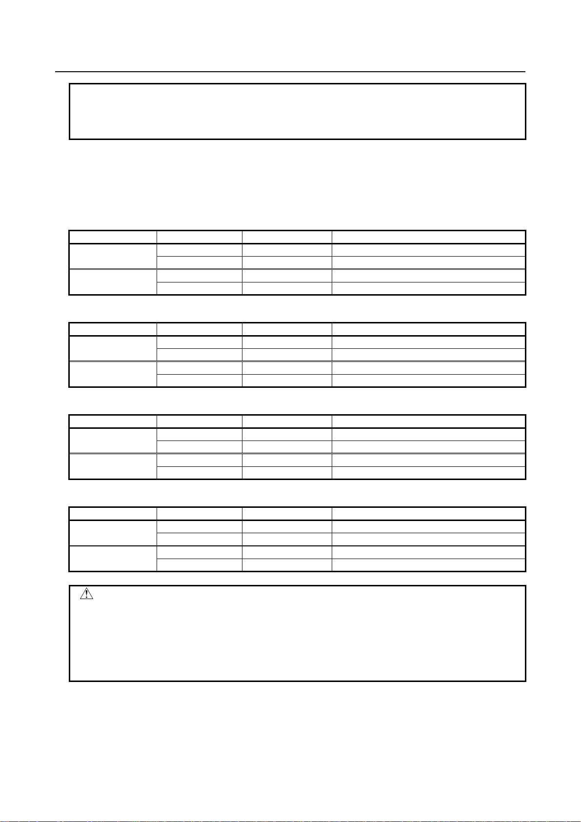
- Standard parameter setting tables
This section defines the standard minimum data units and valid data ranges of the CNC parameters of the
real type, real machine group type, real path type, and real axis type. The data type and unit of data of
each parameter conform to the specifications of each function.
(A) Length and angle parameters (type 1)
Unit of data Increment system Minimum data unit Valid data range
IS-A 0.01 -999999.99 to +999999.99 mm
deg.
inch
IS-B 0.001 -999999.999 to +999999.999
IS-A 0.001 -99999.999 to +99999.999
IS-B 0.0001 -99999.9999 to +99999.9999
(B) Length and angle parameters (type 2)
Unit of data Increment system Minimum data unit Valid data range
IS-A 0.01 0.00 to +999999.99 mm
deg.
inch
IS-B 0.001 0.000 to +999999.999
IS-A 0.001 0.000 to +99999.999
IS-B 0.0001 0.0000 to +99999.9999
(C) Velocity and angular velocity parameters
Unit of data Increment system Minimum data unit Valid data range
IS-A 0.01 0.0 to +999000.00 mm/min
degree/min
inch/min
IS-B 0.001 0.0 to +999000.000
IS-A 0.001 0.0 to +96000.000
IS-B 0.0001 0.0 to +9600.0000
(D) Acceleration and angular acceleration parameters
Unit of data Increment system Minimum data unit Valid data range
IS-A 0.01 0.00 to +999999.99 mm/sec2
IS-B 0.001 0.000 to +999999.999
IS-A 0.001 0.000 to +99999.999
IS-B 0.0001 0.0000 to +99999.9999
deg./sec
inch/sec2
2
CAUTION
1 Values are rounded up or down to the nearest multiples of the minimum data
unit.
2 A valid data range means data input limits, and may differ from values
representing actual performance.
3 For information on the ranges of commands to the CNC, refer to Appendix D,
"Range of Command Value" of the Operator’s Manual (B-64554EN).
p-2
Page 7
B-64560EN/01 PREFACE
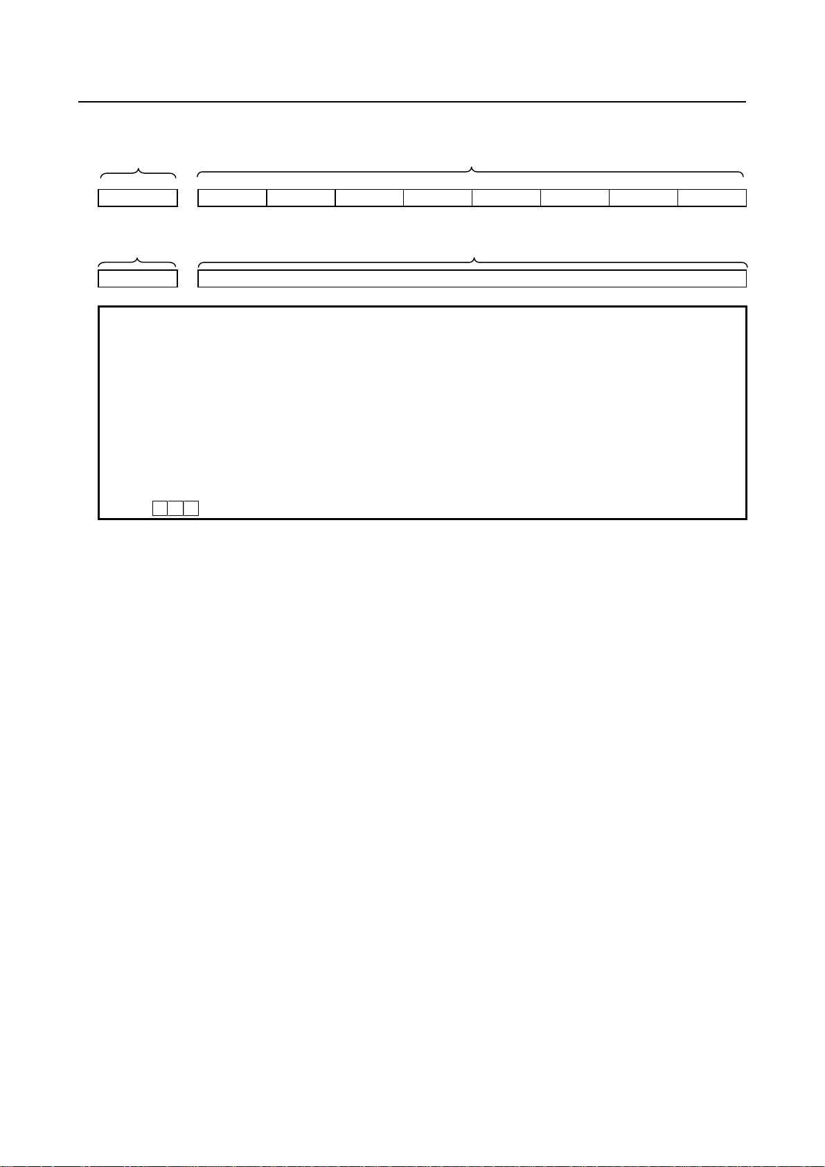
- Parameters of the bit type, bit machine group type, bit path type, and bit axis
type
Data No. Data (Data #0 to #7 are bit positions.)
#7 #6 #5 #4 #3 #2 #1 #0
0000 SEQ INI ISO TVC
- Parameters other than the bit-type parameters above
Data No. Data
1023 Number of the servo axis for each axis
NOTE
1 The bits left blank in “description of parameters” and parameter numbers that
appear on the display but are not found in the parameter list are reserved for
future expansion. They must always be 0.
2 When "to" is inserted between two parameter numbers, there are parameters
with successive numbers between the two starting and ending parameter
numbers, but those intermediate parameter numbers are omitted for
convenience.
3 The lower-case letter "x" following the name of a bit-type parameter indicates the
following:
- ” x” : Bit axis type parameters
p-3
Page 8
PREFACE B-64560EN/01
Related manuals of Series 0i-PD
The following table lists the manuals related to Series 0i-PD. This manual is indicated by an asterisk(*).
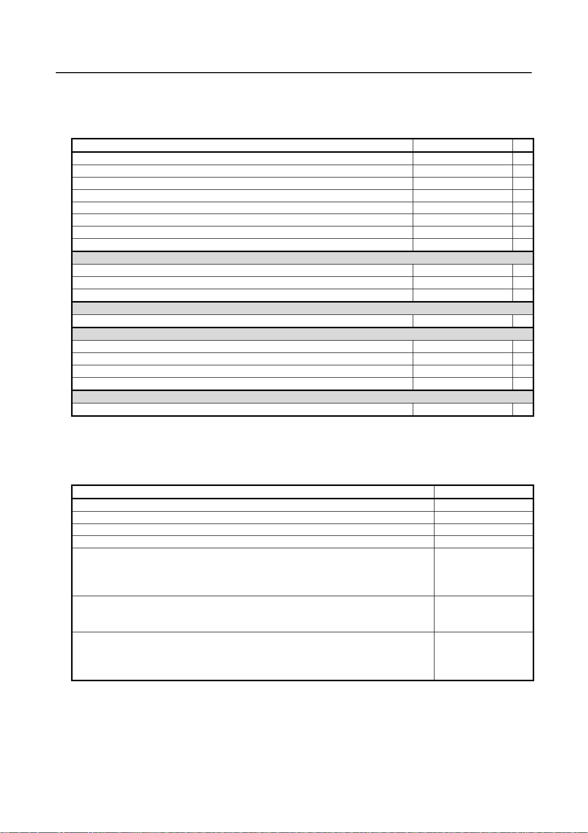
Table 1 Related manuals
Manual name Specification number
FANUC Series 0i-D / 0i Mate-D DESCRIPTIONS
FANUC Series 0i-D / 0i Mate-D CONNECTION MANUAL (HARDWARE)
FANUC Series 0i-D / 0i Mate-D CONNECTION MANUAL (FUNCTION)
FANUC Series 0i-PD CONNECTION MANUAL (FUNCTION)
FANUC Series 0i-PD OPERATOR’S MANUAL
FANUC Series 0i-D / 0i Mate-D MAINTENANCE MANUAL
FANUC Series 0i-D / 0i Mate-D PARAMETER MANUAL
FANUC Series 0i-PD PARAMETER MANUAL
Programming
Macro Executor PROGRAMMING MANUAL B-64303EN-2
Macro Compiler PROGRAMMING MANUAL B-64303EN-5
C Language Executor PROGRAMMING MANUAL B-64303EN-3
PMC
PMC PROGRAMMING MANUAL B-64393EN
Network
PROFIBUS-DP Board CONNECTION MANUAL B-64403EN
Fast Ethernet / Fast Data Server OPERATOR’S MANUAL B-64414EN
DeviceNet Board CONNECTION MANUAL B-64443EN
FL-net Board CONNECTION MANUAL B-64453EN
Dual Check Safety
Dual Check Safety CONNECTION MANUAL B-64303EN-4
B-64302EN
B-64303EN
B-64303EN-1
B-64553EN
B-64554EN
B-64305EN
B-64310EN
B-64560EN *
Related manuals of SERVO MOTOR αi/βi series
The following table lists the manuals related to SERVO MOTOR αi/βi series
Table 2 Related manuals
Manual name Specification number
FANUC AC SERVO MOTOR αi series DESCRIPTIONS
FANUC AC SERVO MOTOR βi series DESCRIPTIONS
FANUC SERVO AMPLIFIER αi series DESCRIPTIONS
FANUC SERVO AMPLIFIER βi series DESCRIPTIONS
FANUC AC SERVO MOTOR αis series
FANUC AC SERVO MOTOR αi series
FANUC AC SPINDLE MOTOR αi series
FANUC SERVO AMPLIFIER αi series MAINTENANCE MANUAL
FANUC AC SERVO MOTOR βis series
FANUC AC SPINDLE MOTOR βi series
FANUC SERVO AMPLIFIER βi series MAINTENANCE MANUAL
FANUC AC SERVO MOTOR αi series
FANUC AC SERVO MOTOR βi series
FANUC LINEAR MOTOR LiS series
FANUC SYNCHRONOUS BUILT-IN SERVO MOTOR DiS series PARAMETER MANUAL
CNCs that are described in this manual can be connected to above servo motors.
This manual mainly assumes that the FANUC SERVO MOTOR αi series of servo motor is used. For
servo motor information, refer to the manuals for the servo motor that are actually connected.
B-65262EN
B-65302EN
B-65282EN
B-65322EN
B-65285EN
B-65325EN
B-65270EN
p-4
Page 9

B-64560EN/01 TABLE OF CONTENTS
TABLE OF CONTENTS
DEFINITION OF WARNING, CAUTION, AND NOTE .................................s-1
PREFACE....................................................................................................p-1
TABLE OF CONTENTS .................................................................................1
1 PARAMETERS FOR THE PRESS FUNCTION ...................................... 1
2 PARAMETERS FOR THE SPEED AND LOOP GAIN SWITCH........... 10
3 PARAMETERS FOR THE NIBBLING FUNCTION ...............................13
4 PARAMETERS FOR THE PATTERN FUNCTION AND THE U/V/W
MACRO FUNCTION (1 OF 2) ............................................................... 16
5 PARAMETERS FOR THE PUNCH AND LASER SWITCH .................. 21
6 PARAMETERS FOR THE TOOL FUNCTION (T FUNCTION) (1 OF 2)23
7 PARAMETERS FOR C–AXIS CONTROL ............................................27
8 PARAMETERS FOR THE SAFETY ZONE........................................... 36
9 PARAMETERS FOR THE DI/DO SIGNALS ......................................... 43
10 PARAMETERS FOR THE Y–AXIS CRACK CANCEL .........................44
11 PARAMETERS FOR THE TOOL FUNCTION (T FUNCTION) (2 OF 2)45
12 PARAMETERS FOR THE PATTERN FUNCTION AND THE U/V/W
MACRO FUNCTION (2 OF 2) ............................................................... 46
13 PARAMETERS FOR THE RAM-AXIS CONTROL................................ 47
14 SPEED AND SERVO PARAMETER SWITCHING PARAMETERS ..... 49
15 PARAMETERS OF POSITIONING BY OPTIMUM ACCELERATION..51
APPENDIX
A CHARACTER CODE LIST .................................................................... 57
c-1
Page 10

Page 11

B-64560EN/01 1.PARAMETERS FOR THE PRESS FUNCTION
1 PARAMETERS FOR THE PRESS
FUNCTION
#7 #6 #5 #4 #3 #2 #1 #0
16000 PEI NFI PFI YSG RPF
NOTE
When this parameter is set, the power must be turned off before
operation is continued.
[Input type] Parameter input
[Data type] Bit path
#2 RPF When the RESET key is pressed or when external reset, reset and rewind, or emergency
stop is activated, the PF signal to start pressing is:
0: Set to “0”.
1: Not set to “0”.
#3 YSG A signal for the press function assigned to an Y address is:
0: Fixed at the address <Y004>.
1: Able to be reassigned to an arbitrary Y address.
NOTE
If bit 3 (YSG) of parameter No.16000 is set to 1, parameter No.
16046 shall be set.
#5 PFI The logic of the *PFIN signal to complete punching for single–cycle pressing is:
0: The same as the logic described in the ”Connection Manual.”
1: The reverse of the logic described in the ”Connection Manual.”
#6 NFI The logic of the *NFIN signal to complete punching for continuous pressing is:
0: The same as the logic described in the “Connection Manual.”
1: The reverse of the logic described in the “Connection Manual.”
#7 PEI The logic of the *PE signal to stop pressing is:
0: The same as the logic described in the “Connection Manual.”
1: The reverse of the logic described in the “Connection Manual.”
#7 #6 #5 #4 #3 #2 #1 #0
16001 CPF MPF PMA PSY PFE MNP
[Input type] Parameter input
[Data type] Bit path
#0 MNP If there remains a distance to be traveled when automatic operation is halted, manual
pressing or continuous manual pressing is:
0: Valid.
1: Invalid.
- 1 -
Page 12

1.PARAMETERS FOR THE PRESS FUNCTION B-64560EN/01
#1 PFE When the PF signal to start pressing is set to “1”, the absolute value of positional
deviation for the X– and Y– axes:
0: Must be less than or equal to the value set in parameter No. 16010.
1: Need not be less than or equal to the value set in parameter No. 16010.
#4 PSY Under axis synchronous control, the PF signal to start pressing is output:
0: Irrespective of the machine coordinates of the synchronous axes.
1: After it has been confirmed that the machine coordinates of the synchronous axes
agree with each other.
If the machine coordinates differ, alarm (PS0213) will be issued and the PF signal
will not be output.
#5 PMA When the AFL signal to lock auxiliary functions is set to “1”, M code signals for forming,
repositioning, and nibbling are:
0: Not output to the machine.
1: Output to the machine.
#6 MPF In a block containing an M code, the PF signal to start pressing is:
0: Not set to “1”.
1: Set to “1”.
PF is set to 1 when movement along an axis terminates or when completion of the
miscellaneous function is returned.
#7 CPF At the end of the 01 group containing the G01, G02, or G03 code, the PF signal to start
pressing is:
0: Not set to “1”.
1: Set to “1”.
#7 #6 #5 #4 #3 #2 #1 #0
16002 EUP PF9 PWB SPR PFB PEM AET
[Input type] Parameter input
[Data type] Bit path
#0 AET The timer for issuing the EF signal to start external operation in advance (parameter No.
16041) is:
0: Disabled.
1: Enabled.
#2 PEM MDI operation:
0: Does not start pressing.
1: Starts pressing.
#3 PFB The PFB signal to start pressing is:
0: Enabled.
1: Disabled.
#4 SPR The *SPR signal to halt automatic operation B is:
0: Invalid.
1: Valid.
#5 PWB The PFWB signal to wait for the start of pressing B is:
0: Invalid.
1: Valid.
- 2 -
Page 13
B-64560EN/01 1.PARAMETERS FOR THE PRESS FUNCTION
#6 PF9 The time interval between setting of the PFB signal to start pressing B to “0” and setting
of the PF signal to start pressing to “0” is set to the value in:
0: Parameter No. 16037.
1: Parameter No. 16038.
#7 EUP By executing the external operation function, the number of punching cycles is:
0: Not aggregated.
1: Aggregated.
One is added when the PF signal to start pressing and the EF signal to external
operation are set to “1”.
#7 #6 #5 #4 #3 #2 #1 #0
16003 NED DPE TCF NPF
[Input type] Parameter input
[Data type] Bit path
#2 NPF The G01, G02, or G03 code specified in normal direction control:
0: Sets PF to “1”.
1: Does not set PF to “1”.
Bit 2 (NPF) of parameter No. 16003 is validated when bit 7 (CPF) of parameter No.
16001 is set to 1.
#5 TCF After the OP signal indicating that automatic operation is in progress is set from “0” to
“1”, the PF signal to start pressing is set to “1”:
0: Only when a T command is found.
This status is the same as the status in which the PFW signal to wait for the start of
pressing is set to “1”.
1: Even if no T commands are found.
#6 DPE The relationship between the *PE signal to stop pressing and the EPE signal for ignoring
the signal to stop pressing is as follows:
0: *PE is always validated irrespective of the status of EPE.
1: *PE is validated when EPE is set to “1”, and invalidated when EPE is set to “0”.
#7 NED After the last positioning ends in a nibbling block, the PF signal to start pressing is set to
“0”:
0: When the contact of the *PE signal to stop pressing is set to “0”.
1: When the two contacts of the *NFIN signal to complete punching for continuous
pressing and the *PE signal stop pressing are set to “0”.
16008 M code for setting the forming mode
16009 M code for canceling the forming mode
[Input type] Parameter input
[Data type] 2-word path
[Valid data range] 1 to 97
Parameter No. 16008 sets the M code for setting the forming mode.
Parameter No. 16009 sets the M code for canceling the forming mode.
- 3 -
Page 14
1.PARAMETERS FOR THE PRESS FUNCTION B-64560EN/01
16010 Upper limit of the position deviation at which PF is set to “1”
[Input type] Parameter input
[Data type] Word axis
[Unit of data] Detection unit
[Valid data range] 0 to 32767
For each axis, parameter No. 16010 sets the upper limit of the positional deviation at
which the PF signal to start pressing is set to “1”. When the absolute value of the
positional deviation does not exceed this highest limit, PF is set to “1”.
Parameter No.16010 is validated when parameter bit 1 (PFE) of parameter No. 16001 is
set to 1.
NOTE
The parameter can only be set for the X, Y, and C axes.
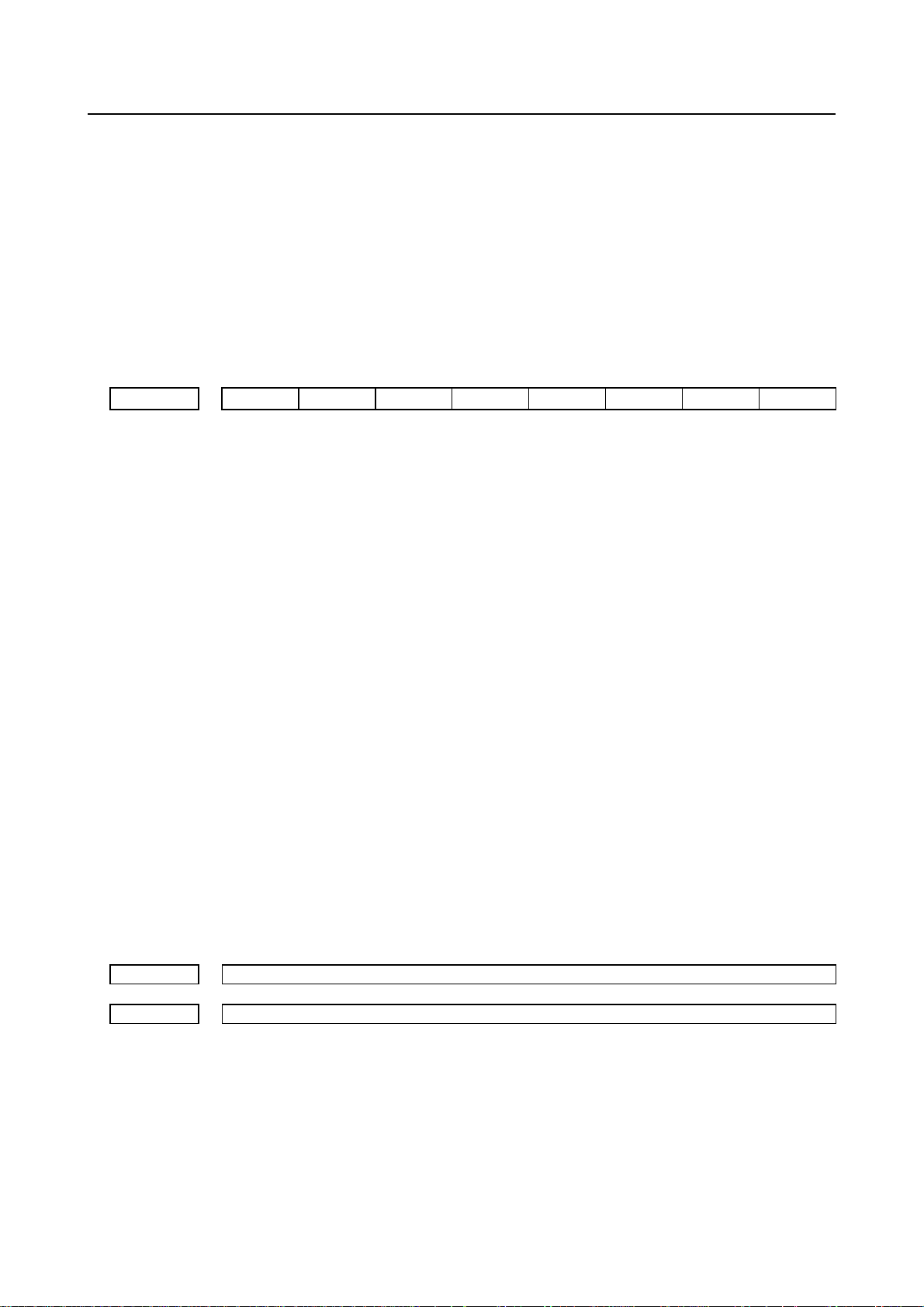
16011 Duration for which the start of positioning is delayed
[Input type] Parameter input
[Data type] Word axis
[Unit of data] msec
[Valid data range] 0 to 248
For each axis, parameter No. 16011 sets the duration for which the start of positioning is
delayed.
NOTE
Only a multiple of 8 can be set for parameter
1
The parameter can only be set for the X, Y, and C axes.
2
Positioning
Positioning in
the next block
No.
16011.
16012 Time interval by which setting of PF to “1” precedes completion of positioning
[Input type] Parameter input
[Data type:] Byte axis
[Unit of data] msec
[Valid data range] -120 to 120
For each axis, parameter No. 16012 sets the time interval by which setting of the PF
signal to start pressing to “1” precedes completion of positioning.(Function to advance
setting of the PF signal)
Time set in parameter No. 16011
- 4 -
Page 15

B-64560EN/01 1.PARAMETERS FOR THE PRESS FUNCTION
NOTE
1 If a negative value is specified, the PF signal is set to “1” when the
corresponding time period elapses after the completion of the
positioning.
2 When bit 0 (OAD) of parameter No. 6131 is set to 1, the data is
invalidated. If it is invalidated, see the descriptions of parameters
Nos. 16857 to 16863.
3 The parameter can only be set for the X, Y, and C axes.
16030
[Input type] Parameter input
[Data type] Word path
[Unit of data] msec
[Valid data range] 0 to 248
16031
[Input type] Parameter input
[Data type] Word path
[Unit of data] msec
[Valid data range] 0 to 248
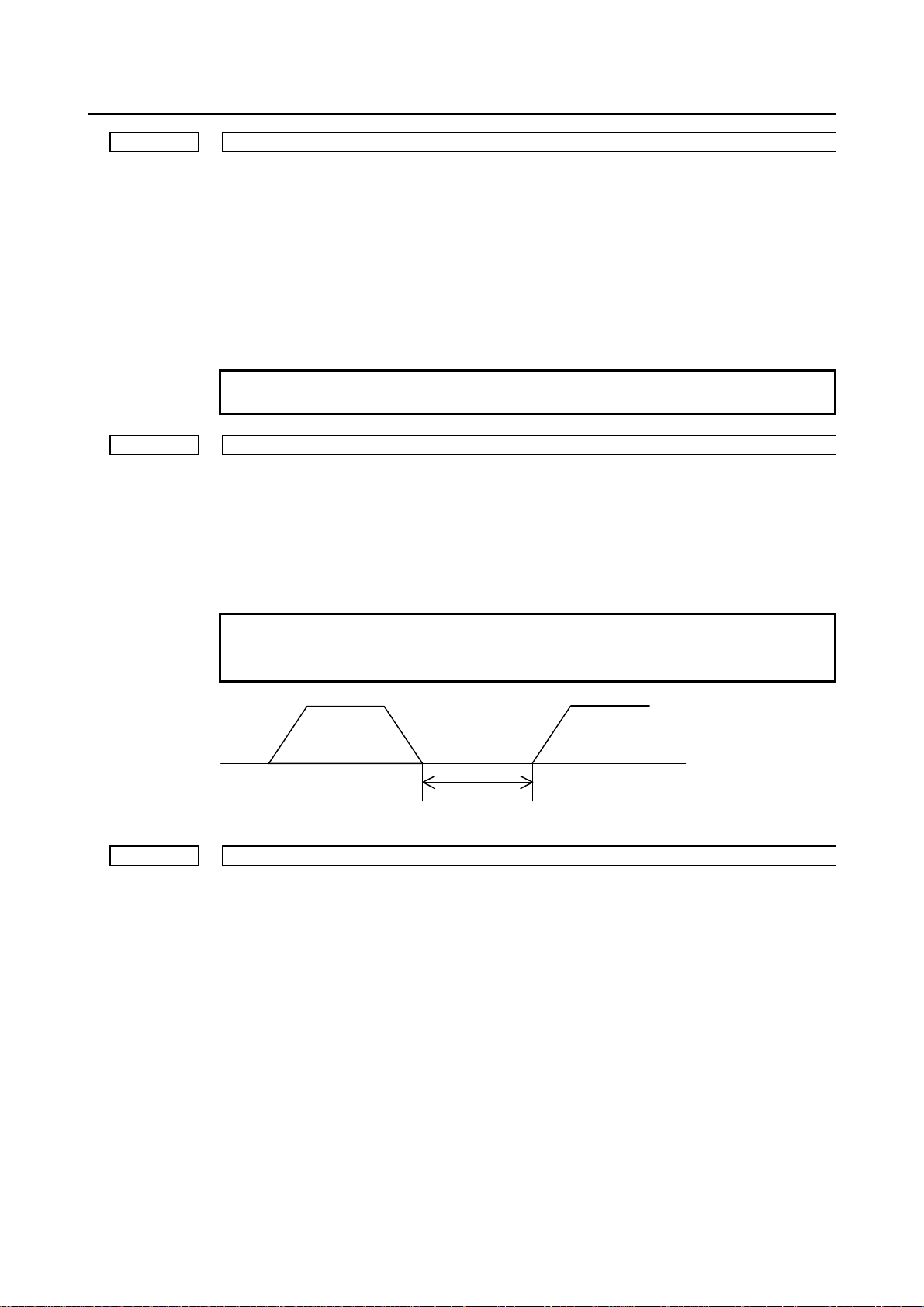
16032 Time interval by which setting of PF to “1” follows positioning in the forming mode
[Input type] Parameter input
[Data type] Word path
[Unit of data] msec
[Valid data range] 0 to 248
16033
[Input type] Parameter input
[Data type] Word path
[Unit of data] msec
[Valid data range] 0 to 248
Time interval by which setting PF to “0” follows setting *PE to “0” in
single–cycle pressing
Parameter No. 16030 sets the time interval by which setting the PF signal to start pressing
to “0” follows setting the contact of the *PE signal to stop pressing to “0” in single–cycle
pressing.
Time interval between completion of positioning and the start of the next
block when PFL is set to “1”
Parameter No. 16031 sets the time interval between completion of positioning and the
start of the next block when are PFL signal to lock the start of pressing is set to “1”.
Parameter No. 16032 sets the time interval by which setting the PF signal to start pressing
to “1” follows positioning in the forming mode (except for nibbling).
Time interval by which the start of the next block follows setting of *PFIN to
“0” in the forming mode
Parameter No. 16033 sets the time interval by which the start of the next block follows
setting the contact of the *PFIN signal to complete punching for single–cycle pressing to
“0” in the forming mode.
- 5 -
Page 16
1.PARAMETERS FOR THE PRESS FUNCTION B-64560EN/01
Positionin
PF
*PFIN
16034 Time interval by which setting PF to “1” follows first positioning in nibbling
[Input type] Parameter input
[Data type] Word path
[Unit of data] msec
[Valid data range] 0 to 248
Parameter No. 16034 sets the time interval by which setting the PF signal to start pressing
to “1” follows positioning at the first punch point in nibbling (nibbling by G68, G69, and
M code).
16035
Time interval by which the start of the next block follows setting *NFIN to “0”
[Input type] Parameter input
[Data type] Word path
[Unit of data] msec
[Valid data range] 0 to 248
Parameter No. 16035 sets the time interval by which the start of the next block follows
setting the contact of the *NFIN signal to complete punching for continuous pressing to
“0” at positioning at the last punch point in nibbling (nibbling by G68, G69, and M code).
16036
Minimum time interval by which setting of PF to “1” follows setting of *PFIN
[Input type] Parameter input
[Data type] Word path
[Unit of data] msec
[Valid data range] 0 to 248
Parameter No. 16036 sets the minimum time interval by which setting the PF signal to
start pressing to “1” follows setting the contact of the *PFIN signal to complete punching
for single–cycle pressing to “0” in single–cycle pressing. After the contact of *PFIN is set
to “0”, PF is set to “1” when the time set here elapses. PF is not set to “1” even if
positioning for the next block completes and other conditions are satisfied before the time
elapses.
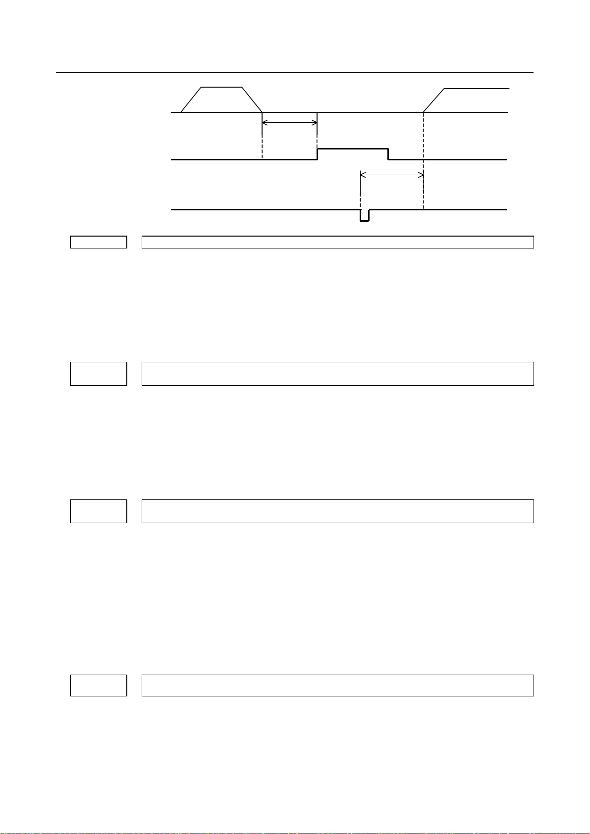
16037
Time interval by which setting PFB to “1” follows setting PF to “1”
[Input type] Parameter input
[Data type] Byte path
[Unit of data] msec
[Valid data range] 0 to 20
Time set in
parameter
No. 16032
at the last positioning in nibbling
and setting PF to “0” follows setting PFB to “0”
Time set in
parameter
No. 16033
to “0” in single–cycle pressing
Next block
- 6 -
Page 17
B-64560EN/01 1.PARAMETERS FOR THE PRESS FUNCTION
Parameter No. 16037 sets the time interval by which setting the PFB signal to start
pressing B to 1follows setting the PF signal to start pressing to “1” and setting PF to “0”
follows setting PFB to “0”.
NOTE
The parameter must be set to 0 when the PFB signal is not used.
PF
PFB
*PE
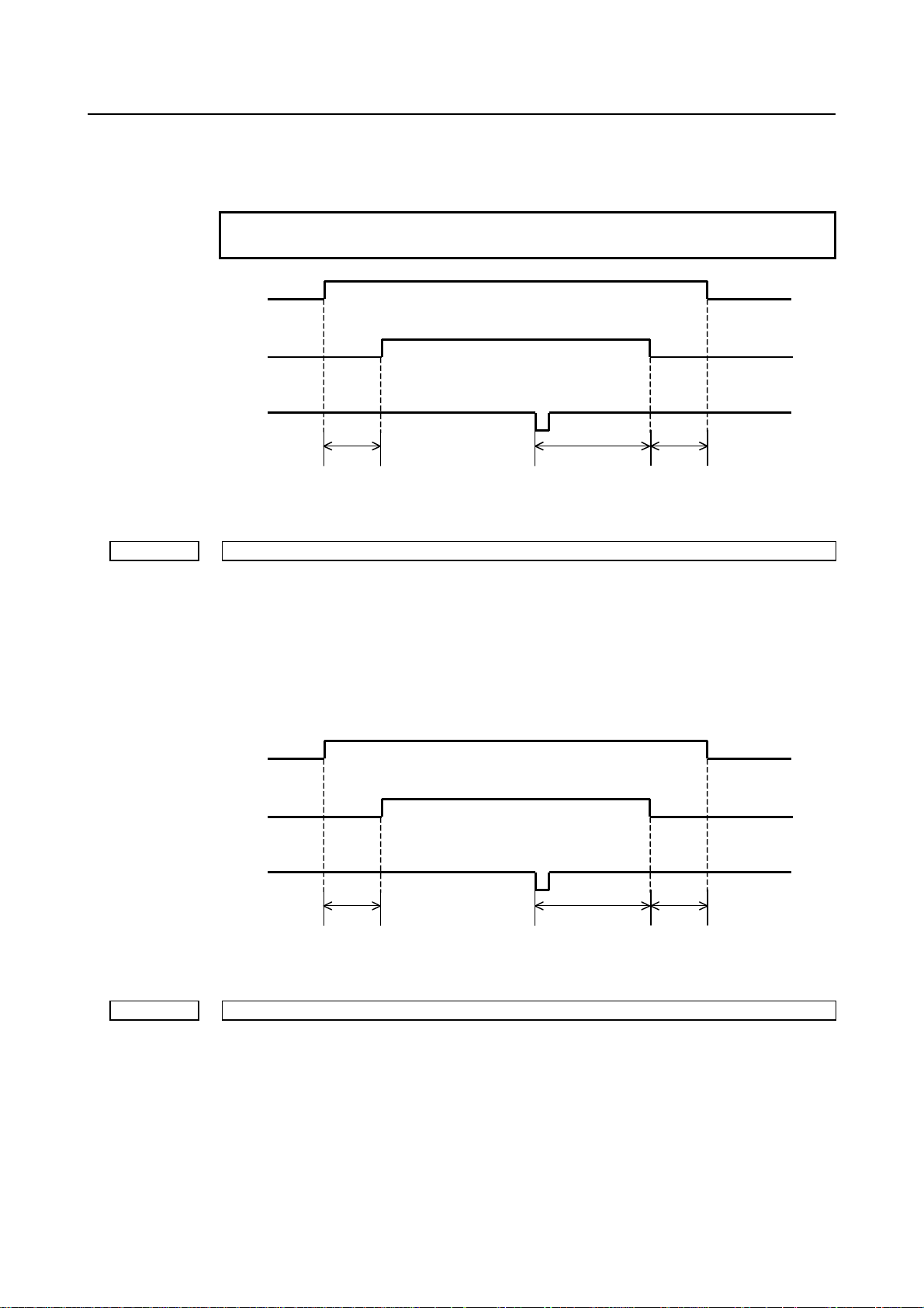
16038 Time interval by which setting PF to “0” follows setting PFB to “0”
[Input type] Parameter input
[Data type] Byte path
[Unit of data] msec
[Valid data range] 0 to 20
Parameter No. 16038 sets the time interval by which setting the PF signal to start pressing
to “0” follows setting the PFB signal to start pressing B to “0”.
The data is validated when bit 6 (PF9) of parameter No. 16002 is set to 1.
PF
PFB
*PE
Time set in
parameter
No. 16037
Time set in
parameter
No. 16030
Time set in
parameter
No. 16037
16039 Time interval by which setting PF to 0 follows setting *PE to “0” in nibbling
[Input type] Parameter input
[Data type] Word path
[Unit of data] msec
[Valid data range] 0 to 248
Parameter No. 16039 sets the time interval by which setting the PF signal to start pressing
to “0” follows setting the contact of the *PE signal to stop pressing to “0” in nibbling.
Time set in
parameter
No. 16037
Time set in
parameter
No. 16030
Time set in
parameter
No. 16038
- 7 -
Page 18

1.PARAMETERS FOR THE PRESS FUNCTION B-64560EN/01
16040 Time interval by which the start of the next block follows setting *PFIN to “0”
[Input type] Parameter input
[Data type] Word path
[Unit of data] msec
[Valid data range] 0 to 248
Parameter No. 16040 sets the time interval by which the start of the next block follows
setting the contact of the *PFIN signal to complete single–cycle pressing to “0” in a block
where the PF signal to start pressing is set to “1” (except for the nibbling or forming
mode).
16041 Time interval by which setting of EF to “1” precedes the completion of positioning
[Input type] Parameter input
[Data type] Byte axis
[Unit of data] msec
[Valid data range] -120 to 120s
This parameter sets the time interval by which setting of the EF signal to “1” by the
external operation function precedes the completion of positioning. If a negative value is
specified, the EF signal is set to “1” when the corresponding time period elapses after the
completion of positioning.
16044 Punching count of every one program execution
[Input type] Setting input
[Data type] 2-word path
[Unit of data] count
[Valid data range] 0 to 99999999
This parameter sets the amount of punching count of every program execution
In other words, this parameter sets the amount of punching count between cycle start
performed and cycle start performed again
When the CNC power-on and cycle start performed, this parameter sets 0
This parameter counts up to 99999999, and counts from 0 again afterwards.
16045
X address to which press stop signal *PE, punch finish signal for 1-cycle press *PFIN, and the press
start waiting signal B PFWB is assigned
NOTE
When this parameter is set, the power must be turned off before
operation is continued.
[Input type] Parameter input
[Data type] word path
[Valid data range] 0 to 327
Set an X address to which press stop signal *PE<X004.7>, punch finish signal for 1-cycle
press *PFIN<X004.5>, and the press start waiting signal B PFWB<X004.4> is to be
assigned.
- 8 -
Page 19
B-64560EN/01 1.PARAMETERS FOR THE PRESS FUNCTION
NOTE
When bit 2 (XSG) of parameter No.3008 is set to 1, the data is
validated.
Depending on the option configuration of the I/O Link expansion,
the actually usable X addresses are:
<X0000 to X0127>, <X0200 to X0327>
16046 Address to which press start signal B PFB and press start signal PF is assigned
NOTE
When this parameter is set, the power must be turned off before
operation is continued.
[Input type] Parameter input
[Data type] word path
[Valid data range] 0 to 327
Set a Y address to which press start signal B PFB<Y004.3> and press start signal
PF<Y004.2> is to be assigned.
NOTE
When bit 3 (YSG) of parameter No. 16000 is set to 1, the data is
validated.
Depending on the option configuration of the I/O Link expansion,
the actually usable Y addresses are:
<Y0 to Y127>, <Y200 to Y327>
16047 Delay time from the punch finish to the table axes movement start
[Input type] Parameter input
[Data type] word path
[Unit of data] msec
[Valid data range] 0 to 248
Set the delay time from setting the punch finish signal for 1-cycle press *PFIN<X004.5>
to “0” to the next block on account of compatible with FANUC Series 0i-PC
- 9 -
Page 20
2.PARAMETERS FOR THE SPEED AND LOOP GAIN SWITCH B-64560EN/01
2 PARAMETERS FOR THE SPEED AND
LOOP GAIN SWITCH
#7 #6 #5 #4 #3 #2 #1 #0
16050 NCT PCF G0F
NOTE
When this parameter is set, the power must be turned off before
operation is continued.
[Input type] Parameter input
[Data type] Bit path
#0 G0F For a rapid traverse command (G00), the X–axis or Y–axis rapid traverse feedrate is set to
the value:
0: Specified in the parameter.
1: Specified by the F code.
The maximum feedrate of the F command is limited to the rapid traverse feedrate in the
parameter. Bit 0 (OADx) of parameter No.6131 and bit 0 (ILG) of parameter No.6132 are
valid.
#1 PCF The X–axis or Y–axis movement mode is selected for the following blocks:
(1) Movement to each punch point with the pattern function (G26, G76, G77, G78, etc.)
(2) Operation in automatic repositioning (G75)
(3) Movement to the first punch point with the nibbling function (G68, G69, and M
code)
0: Rapid traverse is executed.
1: For G00, rapid traverse is executed. For G01, G02, or G03, linear interpolation
cutting feed is executed.
#3 NCT Constant control of positioning time is:
0: Always enabled.
1: Enabled only when the nibbling command is executed.
This parameter is valid when the bit 6 (PT2x) of parameter No.16844 is set to 1.
#7 #6 #5 #4 #3 #2 #1 #0
16051 PGC PLG
NOTE
When this parameter is set, the power must be turned off before
operation is continued.
[Input type] Parameter input
[Data type] Bit path
#6 PLG When the punching and laser modes are used, the servo loop gains of X–axis and Y–axis
position control in cutting feed:
0: Cannot be switched.
1: Can be switched.
- 10 -
Page 21
B-64560EN/01 2.PARAMETERS FOR THE SPEED AND LOOP GAIN SWITCH
#7 PGC Servo loop gains of X–axis and Y–axis position control to be used in rapid traverse and
cutting feed:
0: Are the same.
1: Can be set separately.
See the description of parameter No. 16160.
Servo loop gains to be used in cutting feed are set in parameter No. 16160.
#7 #6 #5 #4 #3 #2 #1 #0
16052 TJG NJC
[Input type] Parameter input
[Data type] Bit path
#0 NJC The jog feedrate is:
0: Limited to the manual rapid traverse rate.
1: Not limited to the manual rapid traverse rate.
#5 TJG The jog override signals for the T–axis and C–axis *JVT1,*JVT2<Gn233.0,.1> are:
0: Not used.
1: Used.
*JVT2 *JVT1 T–axis or C–axis override
0 0 100%
0 1 75%
1 0 50%
1 1 25%
#7 #6 #5 #4 #3 #2 #1 #0
16053 BLN ROM TMO
[Input type] Parameter input
[Data type] Bit path
#0 TMO Override for a linear acceleration/deceleration time constant for rapid traverse is:
0: Disabled
1: Enabled
#2 ROM Rapid traverse override is carried out:
0: According to the specification for the 0i -PD.
1: According to the specification for the 0i -MD.
The PF signal is issued in advance only when the override is100%.
The constant positioning–time control function cannot be used.
#3 BLN For the nibbling command, rapid traverse bell-shaped acceleration/deceleration is:
0: Enabled.
1: Disabled.
#7 #6 #5 #4 #3 #2 #1 #0
16054 NAZ
NOTE
When this parameter is set, the power must be turned off before
operation is continued.
[Input type] Parameter input
- 11 -
Page 22
2.PARAMETERS FOR THE SPEED AND LOOP GAIN SWITCH B-64560EN/01
[Data type] Bit axis
#6 NAZ Specifies whether to make a return to the reference position of the CNC controlled axis
using G28 as follows:
0: Make a return.
1: Do not make a return.
16160 Servo loop gain in cutting feed
[Input type] Parameter input
[Data type] Word axis
[Unit of data] 0.01/sec
[Valid data range] 1 to 9999
For each axis, the parameter sets the servo loop gain of position control in cutting feed.
NOTE
1 The parameter is validated when bit 7 (PGC) of parameter No.
16051 is set to 1.
The parameter can only be set for the X and Y axes.
2
16161 Servo loop gain in cutting feed When the punching modes is used
[Input type] Parameter input
[Data type] Word axis
[Unit of data] 0.01/sec
[Valid data range] 1 to 9999
Sets the loop gain of each axis position control in cutting feed when the punching mode is
used.
When the laser mode is used, the value set in parameter No.16160 is valid.
NOTE
1 The parameter is validated when bit 7 (PGC) of parameter No.
16051 and bit 6 (PLG) of parameter No. 16051 are set to 1.
The parameter can only be set for the X and Y axes.
2
- 12 -
Page 23

B-64560EN/01 3.PARAMETERS FOR THE NIBBLING FUNCTION
3 PARAMETERS FOR THE NIBBLING
FUNCTION
#7 #6 #5 #4 #3 #2 #1 #0
16181 NEF NPF NSP NPC NMG
[Input type] Parameter input
[Data type] Bit path
#0 NMG When the M code for canceling the nibbling mode (No. 16184) is specified, the G code in
the 01 group is:
0: Not changed.
1: Changed to G00 (rapid traverse).
#1 NPC The function to change maximum pitch in the nibbling mode between two levels is:
0: Not used.
1: Used.
The function can be executed by the SNP signal for changing nibbling between two levels
or by the M code (No. 16185).
#2 NSP When the *SP signal to halt automatic operation is set to “0” in nibbling, automatic
operation is:
0: Decelerated and halted immediately.
1: Halted after positioning for a nibbling pitch completes.
#3 NPF In nibbling mode, a press sequence is:
0: Executed according to signals, NBL and *NFIN.
1: Executed according to signals PF, *PFIN, and *PE.
When this parameter is set to 1, a press sequence is executed in the same way as a
sequence for single–cycle press.
#6 NEF In nibbling mode, the
0: Disabled.
1: Enabled.
16183 M code for setting the nibbling mode
[Input type] Parameter input
[Data type] Word path
[Valid data range] 1 to 255
Parameter No.16183 sets the M code for setting the nibbling mode.
16184 M code for canceling the nibbling mode
[Input type] Parameter input
[Data type] Word path
[Valid data range] 1 to 255
Parameter No. 16184 sets the M code for canceling the nibbling mode.
external operation function is:
- 13 -
Page 24

3.PARAMETERS FOR THE NIBBLING FUNCTION B-64560EN/01
16185
M code for setting the nibbling mode in which nibbling is changed between
two levels
[Input type] Parameter input
[Data type] Word path
[Valid data range] 1 to 255
Parameter No. 16185 sets the M code for setting the nibbling mode in which nibbling is
changed between two levels.
NOTE
1 The data is validated when bit 1 (NPC) of parameter No. 16181 is
set to 1.
The M code in parameter
2
if set.
16186
Maximum pitch that can be specified with G01, G02, or G03 for nibbling
by G68 or G69 or by an M code
[Input type] Parameter input
[Data type] Real path
[Unit of data] mm, inch (input unit)
[Min. unit of data] Depend on the increment system of the reference axis
[Valid data range] Positive 9 digit of minimum unit of data
(When the increment system is IS-B, 0.001 to +999999.999)
Parameter No. 16186 specifies the maximum pitch that can be specified with G01, G02,
or G03 for nibbling by G68 or G69 or by an M code.
16188 Maximum pitch of the G00 command for nibbling by the M code
[Input type] Parameter input
[Data type] Real path
[Unit of data] mm, inch (input unit)
[Min. unit of data] Depend on the increment system of the reference axis
[Valid data range] Positive 9 digit of minimum unit of data
(When the increment system is IS-B, 0.001 to +999999.999)
Parameter No. 16188 specifies the maximum pitch of the G00 command for nibbling by
the M code.
Maximum pitch that can be specified with G01, G02, or G03 for nibbling
16190
Maximum pitch of 3rd level for the nibbling parameter switching control using an external signal
by G68 or G69 or by an M code (for changing nibbling between two levels)
[Input type] Parameter input
[Data type] Real path
[Unit of data] mm, inch (input unit)
[Min. unit of data] Depend on the increment system of the reference axis
[Valid data range] Positive 9 digit of minimum unit of data
(When the increment system is IS-B, 0.001 to +999999.999)
When the 2nd level is executed while the function for changing nibbling maximum pitch
between two levels is used, this parameter sets the maximum pitch that can be specified
with G01, G02, or G03 for nibbling by G68 or G69 or by an M code.
When the nibbling parameter switching control using an external signal is used, this
parameter sets the maximum pitch of 3rd level.
- 14 -
16184 is used to cancel the nibbling mode
No.
or
Page 25

B-64560EN/01 3.PARAMETERS FOR THE NIBBLING FUNCTION
16192 Maximum pitch of G00 command by an M code (for changing nibbling between two levels
[Input type] Parameter input
[Data type] Real path
[Unit of data] mm, inch (input unit)
[Min. unit of data] Depend on the increment system of the reference axis
[Valid data range] Positive 9 digit of minimum unit of data
(When the increment system is IS-B, 0.001 to +999999.999)
When the 2nd level is executed while the function for changing nibbling maximum pitch
between two levels is used, this parameter sets the maximum pitch of the G00 command
by an M code.
16194 Maximum distance traveled along C–axis in nibbling
[Input type] Parameter input
[Data type] Real path
[Unit of data] degree (input unit)
[Min. unit of data] Depend on the increment system of the applied axis
[Valid data range] Positive 9 digit of minimum unit of data
(When the increment system is IS-B, 0.001 to +999999.999)
The parameter sets the maximum distance traveled along the C–axis for the nibbling
mode.
- 15 -
Page 26
4. PARAMETERS FOR THE PATTERN FUNCTION AND THE U/V/W MACRO
FUNCTION (1 OF 2)
B-64560EN/01
4 PARAMETERS FOR THE PATTERN
FUNCTION AND THE U/V/W MACRO
FUNCTION (1 OF 2)
#7 #6 #5 #4 #3 #2 #1 #0
16200 UVW ABM MUR UVC
NOTE
When this parameter is set, the power must be turned off before
operation is continued.
[Input type] Parameter input
[Data type] Bit path
#0 UVC In the reset status, the macro stored under a U or V macro number is:
0: Deleted.
1: Not deleted.
#5 MUR U or V macro numbers are handled:
0: According to the standard specifications.
Storage and execution: U1 to 59
Storage: U60 to 89
Representation of several macros: U90 to 99
1: According to the following specifications.
Storage and execution: U1 to 69、90 to 99
Storage: U70 to 79
Representation of several macros: U80 to 89
Macro numbers are handled in the same way as when parameter No. 16206 of the
G73 or G74 command for taking multiple workpieces is set to 2.
NOTE
When bit 5 (MUR) of parameter No.16200 is set to 1, parameter
No. 16206 is invalidated.
#6 ABM To execute a macro function, addresses A, and B:
0: Are used.
1: Are not used. (The A and B axes can be used.)
#7 UVW To execute a macro function, addresses U, V, and W:
0: Are used.
1: Are not used. (The U, V, and W axes can be used.)
#7 #6 #5 #4 #3 #2 #1 #0
16201 MSA AWP IPA APR MLP MPC LIP
[Input type] Parameter input
[Data type] Bit path
- 16 -
Page 27

4.PARAMETERS FOR THE PATTERN FUNCTION AND THE U/V/W MACRO
B-64560EN/01
#0 LIP In the block immediately following setting a local coordinate system (G52), an
incremental command specifies an incremental value from:
0: The origin of the local coordinate system.
1: The current tool position.
#2 MPC When the number of machined workpieces is counted in multiple–workpiece machining:
0: The number of actually machined workpieces is counted.
1: The number is incremented by one when complete machining or remainder
machining is executed (but not when trial machining is executed).
#3 MLP Setting for taking multiple workpieces depends on:
0: The set parameter (No.16206).
1: A signal (MLP1 or MLP2) input from the PMC machine.
#4 APR Upon reset, the compensation value of the reference point in the workpiece coordinate
system in the cause of repositioning
0: Not cleared.
1: Added to the workpiece coordinate system and cleared.
#5 IPA Although positioning is to be executed in the block immediately following execution of
the pattern function (including G68 orG69), only a command for either the X– or Y–axis
is specified. Movement to the pattern reference point:
0: Is not executed for the axis which is not specified.
1: Is executed for the axis which is not specified.
#6 AWP When a workpiece coordinate system is specified, automatic coordinate system setting is
executed as designed for:
0: The FANUC Series 0i-MD.
When manual return to the reference position is completed, the origin of the
coordinate system is shifted by the amount set for the selected workpiece coordinate
system (G54 to G59).
1: The FANUC Series 0i-PD.
When manual return to the reference position is completed, the coordinates of the
automatic coordinate system setting are shifted by the amount set for the selected
workpiece coordinate system (G54 to G59).
#7 MSA When the MUR bit (bit 5 of parameter No. 16200) is set to 1, the machining pattern set
for multiple–workpiece machining is:
0: Disabled.
When this is selected, the value of parameter No. 16206 is always assumed to be 2.
1: Enabled.
#7 #6 #5 #4 #3 #2 #1 #0
16202 AIP
[Input type] Parameter input
[Data type] Bit path
#0 AIP Specifies the condition for the share–proof command (G86).
0: Alarm (PS4506) is issued when I < 1.5P.
1: Alarm (PS4506) is issued when I < P.
FUNCTION (1 OF 2)
- 17 -
Page 28

4. PARAMETERS FOR THE PATTERN FUNCTION AND THE U/V/W MACRO
FUNCTION (1 OF 2)
B-64560EN/01
#7 #6 #5 #4 #3 #2 #1 #0
16203 PCU
[Input type] Parameter input
[Data type] Bit path
#0 PCU The number of machined workpieces is:
0: Counted by an MDI command.
1: Not counted by an MDI command.
#7 #6 #5 #4 #3 #2 #1 #0
16204 PDG BKR
[Input type] Parameter input
[Data type] Bit path
#2 BKR The first automatic repositioning command (G75) that sets automatic operation signal OP
from 0 to 1 uses:
0: The values set in parameter No. 16209 as the clearance and amount of return for the
Y–axis.
(The clearance and amount of return are identical values.)
1: The values set in parameter No. 16209 as the clearance for the Y–axis, and the
values set in parameter No. 16211 as the amount of return.
(The clearance and amount of return are different values.)
#4 PDG On the graphic screen, a program being drawn is:
0: Not displayed.
1: Displayed.
#7 #6 #5 #4 #3 #2 #1 #0
16205 SZR
[Input type] Parameter input
[Data type] Bit path
#0 SZR Automatic reference position return (G28) commands:
0: The axis returns directly to the reference position without passing through any
intermediate points.
1: The axis returns to the reference position via the specified intermediate point.
16206 Machining pattern when multiple workpieces are taken
[Input type] Setting input
[Data type] Byte path
[Valid data range] 0 to 3
Parameter No. 16206 sets a machining pattern when multiple workpieces are taken
- 18 -
Page 29

4.PARAMETERS FOR THE PATTERN FUNCTION AND THE U/V/W MACRO
B-64560EN/01
FUNCTION (1 OF 2)
Settable value
0 A program without the G73 or G74 command for machining when multiple
workpieces are taken is used.
1 A program containing the G73 or G74 command is used and test machining
is executed.
2 A program containing the G73 or G74 command is used and the remaining
processing is executed after test machining.
3 A program containing the G73 or G74 command is used and the entire
machining is executed.
Machining process when multiple workpieces are taken
NOTE
1 When bit 3 (MLP) of parameter No.16201 is set to 0, parameter No.
16206 is validated.
hen
2 W
parameter No. 16206 is set to 0, a
G73 or G74 command is found.
16207 M code for clamping a workpiece
16208 M code for releasing the workpiece
[Input type] Parameter input
[Data type] 2-word path
[Valid data range] 1 to 255
Parameter No. 16207 sets the M code for clamping a workpiece. Parameter No. 16208
sets the M code for releasing the workpiece.
In blocks between the M code for clamping a workpiece and the M code for releasing the
workpiece, the distances traveled along the X–axis and Y–axis are not take into account
in the workpiece coordinate system. The PF signal to start pressing is not set to “1”.
16209 Clearance and amount of return for the Y axis in automatic repositioning
[Input type] Parameter input
[Data type] Real path
[Unit of data] mm, inch (input unit)
[Min. unit of data] Depend on the increment system of the reference axis
[Valid data range] 0 or positive 9 digit of minimum unit of data (refer to standard parameter setting table
(B))
(When the increment system is IS-B, 0.001 to +999999.999)
The parameter sets the clearance and amount of return for the Y–axis in automatic
repositioning (G75).
16211 Amount of return for the Y axis in automatic repositioning
[Input type] Parameter input
[Data type] Real path
[Unit of data] mm, inch (input unit)
[Min. unit of data] Depend on the increment system of the reference axis
[Valid data range] 0 or positive 9 digit of minimum unit of data (refer to standard parameter setting table
(B))
(When the increment system is IS-B, 0.0 to +999999.999)
The parameter sets the amount of return for the Y–axis in automatic repositioning (G75).
The clearance is set in the parameter No. 16209.
larm (PS4539) is issued if the
- 19 -
Page 30

4. PARAMETERS FOR THE PATTERN FUNCTION AND THE U/V/W MACRO
FUNCTION (1 OF 2)
B-64560EN/01
NOTE
This parameter is valid when the BKR bit (bit 2 of parameter No.
16204) is set to 1.
16230 number of machined workpieces in multiple–workpiece machining
[Input type] Setting input
[Data type] 2-word path
[Unit of data] sheet
[Valid data range] 0 to 999999999
When U or V macro or subprogram called using a W code ends while multiple–
workpiece machining is executed by G73 or G74, this parameter increases by 1.
When the CNC is reset or multiple–workpiece machining is not executed, this parameter
sets 0.
- 20 -
Page 31
B-64560EN/01 5.PARAMETERS FOR THE PUNCH AND LASER SWITCH
5 PARAMETERS FOR THE PUNCH AND
LASER SWITCH
#7 #6 #5 #4 #3 #2 #1 #0
16240 RLM RPL
NOTE
When this parameter is set, the power must be turned off before
operation is continued.
[Input type] Parameter input
[Data type] Bit path
#4 RPL When the system is reset, the punch mode and laser mode:
0: Can be switched by bit 5 (RLM) of parameter No.16240.
1: Can not be switched.
#5 RLM When the power is turned on or in the clear status, the machine is set in the:
0: Punch mode.
1: Laser mode.
#7 #6 #5 #4 #3 #2 #1 #0
16241 ILM
[Input type] Parameter input
[Data type] Bit path
#3 ILM In a block other than cutting feed blocks or blocks between the two cutting feed blocks
when the laser mode is selected, the next block is started:
0: After the following is checked: The specified speed is reduced to zero and the
machine reaches the specified position. (A position check is carried out.)
1: After checking that the specified speed is reduced to zero.(No position check is
carried out.)
The parameter is validated when bit 0 (ALA) of parameter No. 16242 is set to 1.
In punching mode, bit 5 (NCI) of parameter No. 1601 is valid.
#7 #6 #5 #4 #3 #2 #1 #0
16242
NOTE
When this parameter is set, the power must be turned off before
operation is continued.
[Input type] Parameter input
[Data type] Bit
#0 ALA Switching between the punch mode and laser mode is:
0: Invalidated.
1: Validated.
ALA
- 21 -
Page 32

5.PARAMETERS FOR THE PUNCH AND LASER SWITCH B-64560EN/01
16244 M code for setting the punch mode
16245 M code for setting the laser mode
[Input type] Parameter input
[Data type] 2-word path
[Valid data range] 0 to 255
Each of the parameters set the M code for setting the punch mode or laser mode.
The parameters are validated when bit 0 (ALA) of parameter No. 16242 is set to 1.
- 22 -
Page 33

B-64560EN/01 6.PARAMETERS FOR THE TOOL FUNCTION (T FUNCTION) (1 OF 2)
6 PARAMETERS FOR THE TOOL FUNCTION
(T FUNCTION) (1 OF 2)
#7 #6 #5 #4 #3 #2 #1 #0
16260 TNM TCL
NOTE
When this parameter is set, the power must be turned off before
operation is continued.
[Input type] Parameter input
[Data type] Bit path
#4 TCL The T axis is:
0: Not controlled by the CNC machine.
1: Controlled the CNC machine.
NOTE
1 When this parameter is set to 1, the T axis should be set as a
rotation axis. (bit 0 (ROTx) of parameter No. 1006 is set to 1)
2 When this parameter is set to 1, setting the following parameters
allows the CNC to be compatible with FANUC Series 0i-PC, as
follows:
Setting Meaning
Bit 0 (ROTx) of parameter No.1006=1
Bit 1 (ROSx) of parameter No.1006=0
Bit 0 (ROAx) of parameter No.1008=1 The rotary axis roll-over is valid.
Bit 1 (RABx) of parameter No.1008=0 The axis rotates in the direction in which
Bit 2 (RRLx) of parameter No.1008=1 Relative coordinates are rounded by the
Rotary axis (A type)
the distance to the target is shorter.
amount of the shift per one rotation
#5 TNM When machine lock signal MLK and the TNG signal for ignoring a T command are on,
whether the number following address T is cataloged as a tool number is:
0: Not checked.
1: Checked.
NOTE
Generally, the tool number is not checked when the TNG
set to “1”.
#7 #6 #5 #4 #3 #2 #1 #0
16262 MBT DTF TNA TND TDP PWT JGT NTD
[Input type] Parameter input
[Data type] Bit path
- 23 -
signal is
Page 34

6.PARAMETERS FOR THE TOOL FUNCTION (T FUNCTION) (1 OF 2) B-64560EN/01
#0 NTD The tool data input screen and the tool number registration screen for multiple tools are:
0: Displayed.
1: Not displayed.
#1 JGT On the position display screen in jog mode and incremental (INC) mode,, a T code (tool
number) is:
0: Not displayed by a signal input from the PMC.
1: Displayed by a signal (addresses G234 to G237) input from the PMC.
#2 PWT When the power is turned on, the T code (tool number) on the position display screen is:
0: Not represented by signal input from the PMC machine.
1: Represented by signal input from the PMC machine (addresses G234 to G237).
#3 TDP On the position screen, a T code is:
0: Not displayed.
1: Displayed.
NOTE
This parameter is invalid when the TCL bit (bit 4 of parameter No.
16260) is set to 1 and when the NDPx bit (bit 0 of parameter No.
3115) is set to 0.
#4 TND When the T–axis position is displayed,
0: The current position is indicated in units of minimum travel increments.
1: The number of the tool at the current position is indicated.
NOTE
This is validated when bit 3 (TDP) of parameter No. 16262 is set to
1.
#5 TNA When a tool number which is not cataloged is specified,
0: Alarm (PS4692) is issued.
1: No alarm are issued but a T code is output.
#6 DTF When T codes are specified in automatic operation, a TF signal for reading the code of
the tool function and the tool function code signal are output:
0: For each T code.
1: For the first T code command when the machine enters the status in which automatic
operation is started from the status in which automatic operation is halted or stopped.
For the second and subsequent T code commands specified until the machine returns
to the status in which automatic operation is halted or stopped, the TF signal and tool
function code signal are output only when the T code signal is different from the
previous one.
#7 MBT In a block in which a T code is specified, buffering is:
0: Executed.
1: Not executed.
#7 #6 #5 #4 #3 #2 #1 #0
16263 NDA IDX ROF TOF ATO OFM
[Input type] Parameter input
[Data type] Bit path
- 24 -
Page 35

B-64560EN/01 6.PARAMETERS FOR THE TOOL FUNCTION (T FUNCTION) (1 OF 2)
#0 OFM In a block containing a T command, the tool position is compensated:
0: Even if there is no movement along an axis.
1: Only when there is movement along an axis. If a block does not contain any
movements along an axis, the compensation is executed in the next block containing
movement along an axis.
#1 ATO The tool position is compensated:
0: Only when a tool command is specified.
1: According to the T code currently specified, even if no tool commands are specified.
#2 TOF The function for compensating the tool position is:
0: Invalidated.
1: Validated.
Specify a tool position compensation value on the tool input screen.
#3 ROF At reset, compensation of tool position is:
0: Not canceled.
1: Canceled.
#6 IDX The tool position is not compensated in a block in which no movement along an axis
occurs. In the next block containing movement along an axis the tool position is
compensated:
0: For each T code.
1: Only for T codes with which turret indexing is not executed.
NOTE
This is validated when bit 0 (OFM) of parameter No. 16263 is set to
1.
#7 NDA If a T command is specified in normal direction mode:
0: An alarm is issued (alarm PS 4606).
1: An alarm is not issued.
If a multi–tool command is specified, however, an alarm is issued.
16265 Total number of tools to be used
[Input type] Parameter input
[Data type] Word path
[Valid data range] 0 to 136
This parameter specifies the total number of tools to be used by the tool function. If
T–axis control is selected (TCL bit (bit 4 of parameter No. 16260) is set to 1), the total
number should include the number of tools for which T–axis control (turret index) is not
executed. This parameter can be specified on the tool input screen. The tool numbers to
be used should be specified on the tool input screen.
16266 Number of tools for which T–axis control is executed
[Input type] Parameter input
[Data type] Word path
[Valid data range] 0 to 136
This parameter specifies the number of tools for which T–axis control (turret index) is
executed. The parameter can be specified on the tool input screen.
- 25 -
Page 36

6.PARAMETERS FOR THE TOOL FUNCTION (T FUNCTION) (1 OF 2) B-64560EN/01
NOTE
This parameter is valid when the TCL bit (bit 4 of parameter No.
16260) is set to 1.
16267 Reference–position tool number under T–axis control
[Input type] Parameter input
[Data type] 2-word path
[Valid data range] 0 to 99999999
This parameter specifies the tool number to be selected upon reference position return for
the T–axis. The parameter can be specified on the tool input screen.
NOTE
This parameter is valid when the TCL bit (bit 4 of parameter No.
16260) is set to 1.
16269 Punching count for all tools (low–order)
16270 Punching count for all tools (high–order)
[Input type] Parameter input
[Data type] 2-word path
[Valid data range] 0 to 99999999
These parameters preset the punching count for all tools to be used.
Parameter No. 16269 and No. 16270 can be preset on the tool input screen.
- 26 -
Page 37

B-64560EN/01 7.PARAMETERS FOR C–AXIS CONTROL
7 PARAMETERS FOR C–AXIS CONTROL
#7 #6 #5 #4 #3 #2 #1 #0
16360 CBR CIP ACS MAB MAI SYN
NOTE
When this parameter is set, the power must be turned off before
operation is continued.
[Input type] Parameter input
[Data type] Bit path
#0 SYN C-axis synchronous control is:
0: Disabled.
1: Enabled.
#2 MAI The function for compensating the C–axis position is:
0: Invalidated.
1: Validated.
#3 MAB The function B for compensating the C-axis position is:
0: Invalidated.
1: Validated.
#4 ACS Under C–axis synchronous control, synchronization is:
0: Invalidated.
1: Validated.
#5 CIP In G01, G02, and G03 modes, a C–axis command is:
0: Invalidated.
1: Validated.
#7 CBR For a tool for which C–axis control can be executed, a C–axis backlash compensation
value is:
0: Not separately specified.
The compensation value set in parameter No.1852 is validated.
1: Separately specified.
The compensation value set in parameter No.1852 is invalidated.
The compensation value for each tool is set in the corresponding parameter among
parameter No.16390 to No.16429.
#7 #6 #5 #4 #3 #2 #1 #0
16362 NRC CRM G92 CNT CR0 RCO
[Input type] Parameter input
[Data type] Bit path
#0 RCO At reset, compensation of C–axis position is:
0: Not canceled.
1: Canceled.
- 27 -
Page 38

7.PARAMETERS FOR C–AXIS CONTROL B-64560EN/01
#1 CR0 When reference position return is performed for the C–axis,:
0: C-axis is positioned to the absolute position set in parameter No.1250.
1: C-axis is positioned to the 1st reference position.
NOTE
This parameter is effective to automatic reference position return
(G28) and reference position return of C-axis under C-axis control.
#2 CNT If a T code with which turret indexing is not executed is specified when the C axis is not
at the reference point, the machine is:
0: Moved along the C–axis to the reference point.
1: Not moved along the C–axis to the reference point.
NOTE
This is validated when bit 5 (CRM) of parameter No. 16362 is set to
0.
#3 G92 Under C–axis control, G92 command for C–axis control is:
0: Invalidated.
1: Validated.
#5 CRM According to a T command, the machine is:
0: Moved along the C–axis to the reference point.
1: Not moved along the C–axis to the reference point.
#7 NRC According to the command of automatic return to the reference point (G28), the machine
is:
0: Moved along the C–axis to the reference point.
1: Not moved along the C–axis to the reference point.
NOTE
This is validated when bit 5 (CRM) of parameter No. 16362 is set to
0.
#7 #6 #5 #4 #3 #2 #1 #0
16363 NDD C2D NDC NDB G91
[Input type] Parameter input
[Data type] Bit path
#0 G91 For C-axis control, a G91 command is:
0: Disabled
1: Enabled
#1 NDB Positioning under normal direction control is carried out:
0: According to the specification for the 0i-MD.
1: By handling the C-axis angle immediately before the beginning of the normal
direction control mode, as an offset value.
#3 NDC Positioning under normal direction control is carried out:
0: According to the specification for the 0i-MD.
1: By handling the C–axis angle immediately before the beginning of the normal
direction control mode, as the direction normal to the next traveling direction.
- 28 -
Page 39

B-64560EN/01 7.PARAMETERS FOR C–AXIS CONTROL
NOTE
When bit 1 (NDB) and bit 3 (NDC) of parameter No. 16363 are set
to 1, the movement specified by bit 1 (NDB) of parameter No.
16363 has priority over the movement by bit 3 (NDC) of parameter
No. 16363.
#6 C2D C–axis non-synchronization control signal C2DABL<Gn231.7> is:
0: Disabled.
1: Enabled.
NOTE
When C–axis synchronization control is used, this parameter is
enabled.
#7 NDD When circular interpolation (G02, G03) is specified under normal direction control and
the rotation insertion angle calculated during normal direction control does not exceed the
value is set in the parameter No.5482,:
0: The CNC gentles normal direction control axis simultaneously with the X/Y-axis
motion.(FANUC Series 0i-PC system compatible specification)
1: The CNC moves normal direction control axis to the end of the block. (FANUC
Series 0i-PD system specification)
16364 Upper limit of error under C–axis synchronous control
[Input type] Parameter input
[Data type] 2-word path
[Unit of data] Detection unit
[Valid data range] 0 to 999999999
When the absolute value of the position error between the C
1–axis and C2–axis exceeds
the value set in this parameter under C–axis synchronous control, alarm (DS4603) occurs.
NOTE
This parameter is valid when the SYN bit (bit 0 of parameter No.
16360) is set to 1.
16365 Upper limit of error under C–axis synchronous control (during continuous pressing)
[Input type] Parameter input
[Data type] 2-word path
[Unit of data] Detection unit
[Valid data range] 0 to 999999999
When the absolute value of the position error between the C
1–axis and C2–axis exceeds
the value set in this parameter while continuous pressing signal NBL is set to “1”, alarm
(DS4603) occurs.
NOTE
This parameter is valid when the SYN bit (bit 0 of parameter No.
16360) is set to 1.
- 29 -
Page 40

7.PARAMETERS FOR C–AXIS CONTROL B-64560EN/01
16368 Maximum compensation in C–axis synchronization
[Input type] Parameter input
[Data type] Real path
[Unit of data] degree (machine unit)
[Min. unit of data] Depend on the increment system of the reference axis
[Valid data range] 0 or positive 9 digit of minimum unit of data (refer to the standard parameter setting
table(B))
(When the increment system is IS-B, 0.0 to +999999.999)
This parameter specifies the maximum compensation in C–axis synchronization under
C–axis synchronous control. If an actual compensation value exceeds this value, alarm
(SV0410) occurs in the stop state or during travel.
NOTE
This parameter is valid when the ACS bit (bit 4 of parameter No.
16360) is set to 1.
16370 Number of tool 1 for which C–axis control can be executed
16371 Number of tool 2 for which C–axis control can be executed
16372 Number of tool 3 for which C–axis control can be executed
16373 Number of tool 4 for which C–axis control can be executed
16374 Number of tool 5 for which C–axis control can be executed
16375 Number of tool 6 for which C–axis control can be executed
16376 Number of tool 7 for which C–axis control can be executed
16377 Number of tool 8 for which C–axis control can be executed
16378 Number of tool 9 for which C–axis control can be executed
16379 Number of tool 10 for which C–axis control can be executed
16380 Number of tool 11 for which C–axis control can be executed
16381 Number of tool 12 for which C–axis control can be executed
16382 Number of tool 13 for which C–axis control can be executed
16383 Number of tool 14 for which C–axis control can be executed
16384 Number of tool 15 for which C–axis control can be executed
16385 Number of tool 16 for which C–axis control can be executed
16386 Number of tool 17 for which C–axis control can be executed
16387 Number of tool 18 for which C–axis control can be executed
- 30 -
Page 41

B-64560EN/01 7.PARAMETERS FOR C–AXIS CONTROL
16388 Number of tool 19 for which C–axis control can be executed
16389 Number of tool 20 for which C–axis control can be executed
[Input type] Parameter input
[Data type] 2-word path
[Valid data range] 0 to 99999999
Each of the parameters set the number of a tool for which C–axis control can be executed.
C–axis control can be effective for the tool set to this parameter.
16390 C-axis backlash 1
16391 C-axis backlash 2
16392 C-axis backlash 3
16393 C-axis backlash 4
16394 C-axis backlash 5
16395 C-axis backlash 6
16396 C-axis backlash 7
16397 C-axis backlash 8
16398 C-axis backlash 9
16399 C-axis backlash 10
16400 C-axis backlash 11
16401 C-axis backlash 12
16402 C-axis backlash 13
16403 C-axis backlash 14
16404 C-axis backlash 15
16405 C-axis backlash 16
16406 C-axis backlash 17
16407 C-axis backlash 18
16408 C-axis backlash 19
16409 C-axis backlash 20
[Input type] Parameter input
[Data type] Word path
[Unit of data] Detection unit
[Valid data range] -9999 to 9999
- 31 -
Page 42
7.PARAMETERS FOR C–AXIS CONTROL B-64560EN/01
Each of these parameters specifies a C–axis backlash for each tool for which C–axis
control can be executed (C
1–axis backlash under C–axis synchronous control).
The parameter values correspond to the tool numbers specified in parameter Nos. 16370
to 16389, respectively.
NOTE
These parameters are valid when the CBR bit (bit 7 of parameter
16360) is set to 1. When these parameters are valid, the C–axis
backlash specified in parameter No. 1852 is invalid.
16410 C2 axis backlash 1
16411 C2 axis backlash 2
16412 C2 axis backlash 3
16413 C2 axis backlash 4
16414 C2 axis backlash 5
16415 C2 axis backlash 6
16416 C2 axis backlash7
16417 C2 axis backlash8
16418 C2 axis backlash 9
16419 C2 axis backlash 10
16420 C2 axis backlash 11
16421 C2 axis backlash 12
16422 C2 axis backlash 13
16423 C2 axis backlash 14
16424 C2 axis backlash 15
16425 C2 axis backlash 16
16426 C2 axis backlash 17
16427 C2 axis backlash 18
16428 C2 axis backlash 19
16429 C2 axis backlash 20
[Input type] Parameter input
[Data type] Word path
[Unit of data] Detection unit
[Valid data range] -9999 to 9999
- 32 -
Page 43
B-64560EN/01 7.PARAMETERS FOR C–AXIS CONTROL
Each of these parameters specifies a C2–axis backlash for each tool for which C–axis
control can be executed.
The parameter values correspond to the tool numbers specified in parameter Nos. 16370
to 16389, respectively.
NOTE
These parameters are valid when both the SYN and CBR bits (bits
0 and 7 of parameter 16360) are set to 1. When these parameters
are valid, the C–axis backlash specified in parameter No. 1852 is
invalid.
16430 C–axis position compensation 1
16431 C–axis position compensation 2
16432 C–axis position compensation 3
16433 C–axis position compensation 4
16434 C–axis position compensation 5
16435 C–axis position compensation 6
16436 C–axis position compensation 7
16437 C–axis position compensation 8
16438 C–axis position compensation 9
16439 C–axis position compensation 10
16440 C–axis position compensation 11
16441 C–axis position compensation 12
16442 C–axis position compensation 13
16443 C–axis position compensation 14
16444 C–axis position compensation 15
16445 C–axis position compensation 16
16446 C–axis position compensation 17
16447 C–axis position compensation 18
16448 C–axis position compensation 19
16449 C–axis position compensation 20
[Input type] Parameter input
[Data type] Real path
[Unit of data] degree (machine unit)
- 33 -
Page 44

7.PARAMETERS FOR C–AXIS CONTROL B-64560EN/01
[Min. unit of data] Depend on the increment system of the reference axis
[Valid data range] 9 digit of minimum unit of data (refer to standard parameter setting table (A))
(When the increment system is IS-B, -999999.999 to +999999.999)
Each of these parameters specifies a C–axis position compensation value (C
1–axis
backlash under C–axis synchronous control).
These compensated values correspond to the tool numbers set in parameter Nos. 16370 to
16389.
NOTE
The values validated when bit 2 (MAI) of parameter MAI is set to 1.
16450 C2–axis position compensation 1
16451 C2–axis position compensation 2
16452 C2–axis position compensation 3
16453 C2–axis position compensation 4
16454 C2–axis position compensation 5
16455 C2–axis position compensation 6
16456 C2–axis position compensation 7
16457 C2–axis position compensation 8
16458 C2–axis position compensation 9
16459 C2–axis position compensation 10
16460 C2–axis position compensation 11
16461 C2–axis position compensation 12
16462 C2–axis position compensation 13
16463 C2–axis position compensation 14
16464 C2–axis position compensation 15
16465 C2–axis position compensation 16
16466 C2–axis position compensation 17
16467 C2–axis position compensation 18
16468 C2–axis position compensation 19
16469 C2–axis position compensation 20
[Input type] Parameter input
[Data type] Real path
- 34 -
Page 45

B-64560EN/01 7.PARAMETERS FOR C–AXIS CONTROL
[Unit of data] degree (machine unit)
[Min. unit of data] Depend on the increment system of the reference axis
[Valid data range] 9 digit of minimum unit of data (refer to standard parameter setting table (A))
(When the increment system is IS-B, -999999.999 to +999999.999)
Each of these parameters specifies a C
–axis position compensation value.
2
These compensated values correspond to the tool numbers set in parameter Nos. 16370 to
16389.
NOTE
These parameters are valid when both the SYN and MAI bits (bits
0 and 2 of parameter No. 16360) are set to 1.
16480 Axis number of C2–axis under C–axis synchronization control
NOTE
When this parameter is set, the power must be turned off before
operation is continued.
[Input type] Parameter input
[Data type] Word path
[Valid data range] 0 to Number of controlled axes
This parameter sets the axis number of the C
-axis under C–axis synchronization control.
2
NOTE
These parameters are valid when both the SYN bit (bits 0 of
parameter No. 16360) are set to 1.
- 35 -
Page 46
8.PARAMETERS FOR THE SAFETY ZONE B-64560EN/01
8 PARAMETERS FOR THE SAFETY ZONE
#7 #6 #5 #4 #3 #2 #1 #0
16500 YSF SAT SF0
NOTE
When this parameter is set, the power must be turned off before
operation is continued.
[Input type] Parameter input
[Data type] Bit path
#0 SF0 The safety zone of type:
0: A is used.
1: B is used.
#5 SAT When punching is inhibited in the safety zone, the block in which a T command is
specified is checked:
0: In advance.
1: After the FIN signal to complete the T command has been received.
#7 YSF When a safety zone check is executed, the inhibited area along the Y axis extends from
the values:
0: In the negative direction.
1: In the positive direction.
#7 #6 #5 #4 #3 #2 #1 #0
16501 SZ4 SZ3 SZ2 SZ1
[Input type] Parameter input
[Data type] Bit path
#0 to 3 SFj When a safety zone check is executed, in the #j (j=1 to 4) area,
0: An entry is inhibited.
1: Punching is inhibited.
NOTE
When type B of safety zone check is used, this parameter is
disabled.
#7 #6 #5 #4 #3 #2 #1 #0
16502 SOF ZNO SZI GSZ ZIO SZC MDP
[Input type] Parameter input
[Data type] Bit path
#0 MDP On the safety zone setting display,
0: The workpiece coordinate system is indicated.
1: The machine coordinate system is indicated.
- 36 -
Page 47

B-64560EN/01 8.PARAMETERS FOR THE SAFETY ZONE
#1 SZC On the safety zone setting display, the data for:
0: Any zone can be changed.
1: Those zones to be set automatically (parameter No. 16534) can be changed.
#2 ZIO When the safety zone is automatically set by an external signal, the position of a
workpiece holder is detected according to:
0: The on and off states of the SAFZ signal used to detect the position of a workpiece
holder.
1: The on state of the SAFZ signal used to detect the position of a workpiece holder.
#3 GSZ On the graphic screen, the safety zone is checked according to the position of a workpiece
holder:
0: Specified on the safety zone screen.
1: Specified by graphic parameters.
(On the graphic screen, this check is executed in an area that is not related to the
actual machining check.)
#4 SZI Data set on the safety zone setting display is:
0: Invalidated.
1: Validated.
#5 ZNO In the safety zone area setting screen of the safety zone B specification, :
0: Number of zone and other number than number of zone can be inputted.
1: Number of zone can be inputted.
#7 SOF In the safety zone check, tool position compensation is:
0: Not considered.
1: Considered.
#7 #6 #5 #4 #3 #2 #1 #0
16504 RTZ SPA
[Input type] Parameter input
[Data type] Bit path
#0 SPA In the case of type A of the safety zone check, when the end point of positioning is in the
safety zone or the tool path is interfered with the safety zone, :
0: An alarm is not given.
1: An alarm is given without moving the axis. (Previous check)
#1 RTZ In the safety zone check, setting area of the circle tool figure is:
0: Disabled.
1: Enabled.
16505 Positive X coordinate for safety zone 1
16506 Negative X coordinate for safety zone 1
16507 Y coordinate for safety zone 1
16508 Positive X coordinate for safety zone 2
16509 Negative X coordinate for safety zone 2
- 37 -
Page 48

8.PARAMETERS FOR THE SAFETY ZONE B-64560EN/01
16510 Y coordinate for safety zone 2
16511 Positive X coordinate for safety zone 3
16512 Negative X coordinate for safety zone 3
16513 Y coordinate for safety zone 3
16514 Positive X coordinate for safety zone 4
16515 Negative X coordinate for safety zone 4
16516 Y coordinate for safety zone 4
[Input type] Parameter input
[Data type] Real path
[Unit of data] mm, inch (machine unit)
[Min. unit of data] Depend on the increment system of the reference axis
[Valid data range] 9 digit of minimum unit of data (refer to standard parameter setting table (A))
(When the increment system is IS-B, -999999.999 to +999999.999)
Each set of the parameters specify safety zone 1, 2, 3, or 4.
NOTE
1 Set four safety zones to be arranged sequentially in the order of #1,
#2, #3 and #4 from the origin to positive of the X–axis.
2 Zeros must be specified for zones which need not be
16517 Size of tool area 1 in the X direction
16518 Size of tool area 1 in the Y direction
16519 Size of tool area 2 in the X direction
16520 Size of tool area 2 in the Y direction
16521 Size of tool area 3 in the X direction
16522 Size of tool area 3 in the Y direction
16523 Size of tool area 4 in the X direction
16524 Size of tool area 4 in the Y direction
16525 Size of tool area 5 in the X direction
16526 Size of tool area 5 in the Y direction
16527 Size of tool area 6 in the X direction
16528 Size of tool area 6 in the Y direction
16529 Size of tool area 7 in the X direction
specified.
- 38 -
Page 49

B-64560EN/01 8.PARAMETERS FOR THE SAFETY ZONE
16530 Size of tool area 7 in the Y direction
16531 Size of tool area 8 in the X direction
16532 Size of tool area 8 in the Y direction
[Input type] Parameter input
[Data type] Real path
[Unit of data] mm, inch (machine unit)
[Min. unit of data] Depend on the increment system of the reference axis
[Valid data range] 0 or Positive 9 digit of minimum unit of data (refer to standard parameter setting table
(B))
(When the increment system is IS-B, 0.0 to +999999.999)
In the safety zone check, each set of the parameters specify tool area 1, 2, 3, 4, 5, 6, 7,or
8.
Tool area 9, 10, 11, or 12 are specified by setting each set of the parameters among
Nos.16551 to 16558.
NOTE
A tool area is selected by signals SZTS0 to SZTS3 input
PMC machine.
16533 Distance between the position detector of the workpiece holder and the punch
[Input type] Parameter input
[Data type] Real path
[Unit of data] mm, inch (machine unit)
[Min. unit of data] Depend on the increment system of the reference axis
[Valid data range] 9 digit of minimum unit of data (refer to standard parameter setting table (A))
(When the increment system is IS-B, -999999.999 to +999999.999)
The parameter sets the distance between the position detector of the workpiece holder and
punch.
The sign of the value set in the parameter corresponds to the direction the machine travels
along the X–axis, assuming the punch position as zero.
16534 Number of zones to be detected for automatic setting of a safety zone
[Input type] Parameter input
[Data type] Byte path
[Unit of data] Piece
[Valid data range] 0 to 4
This parameter specifies the number of zones to be detected for automatic setting of a
safety zone by an external signal.
from a
NOTE
This parameter must be specified when automatic setting
1
is executed.
of a
safety zone
2 When the set parameter is outside the valid data range, the CNC
clamps the internal data to the maximum value and minimum
value.
16535 Retraction position from the X–axis reference position for automatic setting of a safety zone
[Input type] Parameter input
- 39 -
Page 50

8.PARAMETERS FOR THE SAFETY ZONE B-64560EN/01
[Data type] Real path
[Unit of data] mm, inch (machine unit)
[Min. unit of data] Depend on the increment system of the reference axis
[Valid data range] 9 digit of minimum unit of data (refer to standard parameter setting table (A))
(When the increment system is IS-B, -999999.999 to +999999.999)
This parameter specifies a clearance from the X–axis reference position for automatic
setting of a safety zone by means of an external signal.
NOTE
Specify a position that is sufficiently distant to allow the speed at which
the position of a workpiece holder is detected to become stable.
16536 X–axis rapid traverse rate for automatic setting of a safety zone
[Input type] Parameter input
[Data type] Real path
[Unit of data] mm, inch (machine unit)
[Min. unit of data] Depend on the increment system of the reference axis
[Valid data range] Refer to standard parameter setting table (C)
(When the increment system is IS-B, 0.0 to +999000.000)
This parameter specifies an X–axis rapid traverse rate for automatic setting of a safety
zone by an external signal.
NOTE
When this parameter is set to 0, the feedrate along the X–axis for
automatic detection equals the manual rapid traverse rate (parameter
1424).
No.
16537 X–axis rapid traverse time constant for automatic setting of a safety zone
[Input type] Parameter input
[Data type] Word path
[Unit of data] msec
[Valid data range] 8 to 4000
This parameter specifies an X–axis rapid traverse time constant for the automatic setting
of a safety zone by an external signal.
NOTE
When this parameter is set to 0, the X–axis time constant for
automatic detection equals the time constant for manual rapid traverse
(parameter
16538 Lower limit of position error for movement along the X–axis for automatic setting of a safety zone
16539 Upper limit of position error for movement along the X–axis for automatic setting of a safety zone
[Input type] Parameter input
[Data type] 2-word path
[Unit of data] Detection unit
[Valid data range] 0 to 99999999 (8 digit)
No.
1620).
- 40 -
Page 51

B-64560EN/01 8.PARAMETERS FOR THE SAFETY ZONE
These parameters specify the lower and upper limits, for the position error for movement
along the X–axis, for the automatic setting of a safety zone by an external signal.
NOTE
1 These parameters must be specified for automatic setting of a
safety zone.
The values of these parameters must satisfy the following condition:
2
Parameter
16538 < Parameter
No.
No.
16539
16540 Width of workpiece holder 1 along the X–axis for automatic setting of a safety zone
16541 Width of workpiece holder 2 along the X–axis for automatic setting of a safety zone
16542 Width of workpiece holder 3 along the X–axis for automatic setting of a safety zone
16543 Width of workpiece holder 4 along the X–axis for automatic setting of a safety zone
[Input type] Parameter input
[Data type] Real path
[Unit of data] mm, inch (machine unit)
[Min. unit of data] Depend on the increment system of the reference axis
[Valid data range] 0 or positive 9 digit of minimum unit of data (refer to standard parameter setting table
(B))
(When the increment system is IS-B, 0.0 to +999999.999)
Each of the parameters specifies the width of a workpiece holder along the X–axis for the
automatic setting of a safety zone by an external signal.
The parameter values correspond to safety zones 1 to 4, specified in parameter Nos.
16505 to 16516, respectively.
NOTE
When automatic setting is executed, these parameters must be set.
16551 X dimension of tool area 9
16552 Y dimension of tool area 9
16553 X dimension of tool area 10
16554 Y dimension of tool area 10
16555 X dimension of tool area 11
16556 Y dimension of tool area 11
16557 X dimension of tool area 12
16558 Y dimension of tool area 12
[Input type] Parameter input
[Data type] Real path
[Unit of data] mm, inch (machine unit)
[Min. unit of data] Depend on the increment system of the reference axis
- 41 -
Page 52

8.PARAMETERS FOR THE SAFETY ZONE B-64560EN/01
[Valid data range] 0 or Positive 9 digit of minimum unit of data (refer to standard parameter setting table
(B))
(When the increment system is IS-B, 0.0 to +999999.999)
In the safety zone check, each set of the parameters specifies tool area 9, 10, 11, or 12.
Tool area 1, 2, 3, 4, 5, 6, 7,or 8 is specified by setting each set of the parameters among
Nos.16517 to 16532.
NOTE
A tool area is selected by signals SZTS0 to SZTS3 input from a PMC
machine.
- 42 -
Page 53
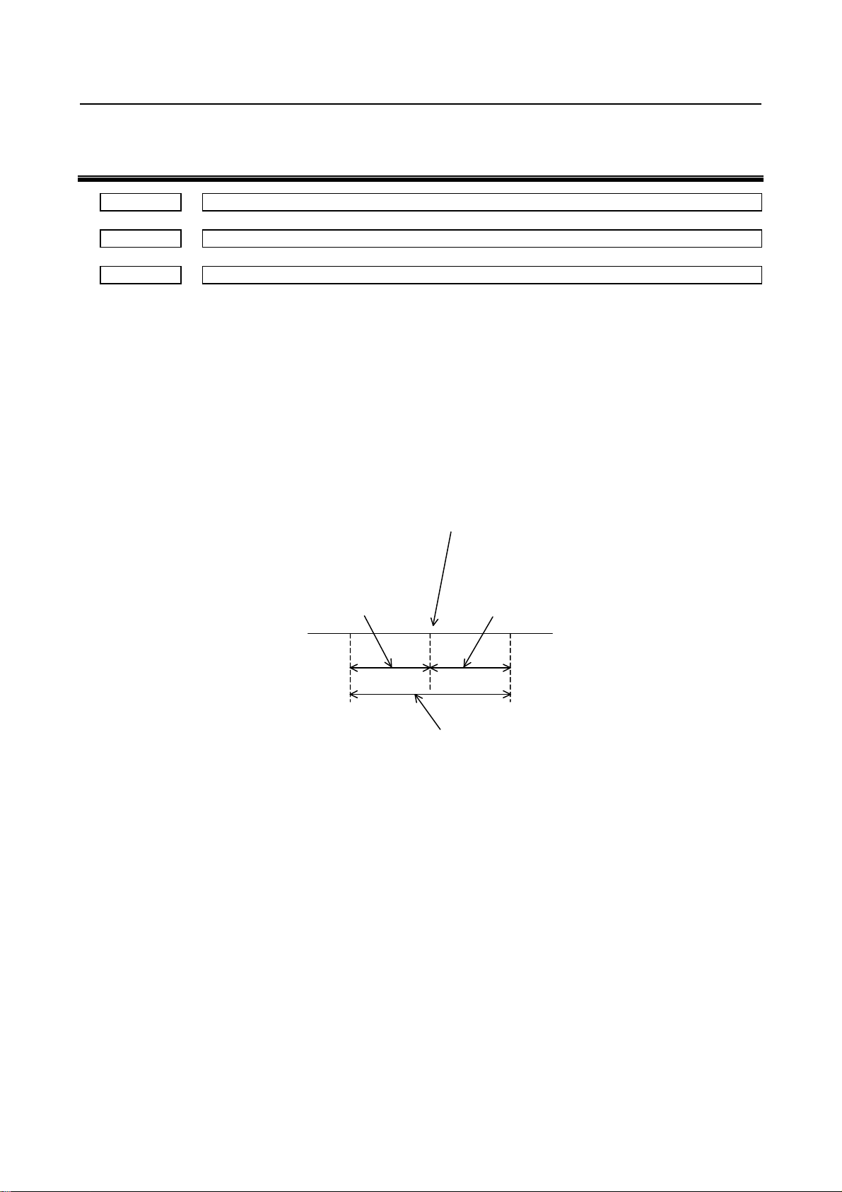
B-64560EN/01 9.PARAMETERS FOR THE DI/DO SIGNALS
9 PARAMETERS FOR THE DI/DO SIGNALS
16600 Width for which the second reference position signal is output on each axis
16601 Width for which the third reference position signal is output on each axis
16602 Width for which the fourth reference position signal is output on each axis
[Input type] Parameter input
[Data type] Real axis
[Unit of data] mm, inch (machine unit)
[Min. unit of data] Depend on the increment system of the applied axis
[Valid data range] 0 or Positive 9 digit of minimum unit of data (refer to standard parameter setting table
(B))
(When the increment system is IS-B, 0.0 to +999999.999)
The parameters specify the width for the second, third, or fourth reference position of the
machine coordinate system. The second, third, or fourth reference position signal is
output within the range shown below:
Value specified in
parameter No.16600,
16601, or 16602
Negative direction
Second, third, or fourth referenc e position s ign al for whic h are output
Position specified in parameter No.1241, 1242, or 1243
Value specified in
●
parameter No.16600,
16601, or 16602
Positive direction
- 43 -
Page 54

10.PARAMETERS FOR THE Y–AXIS CRACK CANCEL B-64560EN/01
10 PARAMETERS FOR THE Y–AXIS CRACK
CANCEL
16610 M code 1 for canceling the Y–axis crack
16611 M code 2 for canceling the Y–axis crack
16612 M code 3 for canceling the Y–axis crack
16613 M code 4 for canceling the Y–axis crack
16614 M code 5 for canceling the Y–axis crack
[Input type] Parameter input
[Data type] 2-word path
[Valid data range] 0 to 65535
Set an M code for Y-axis crack cancel.
The cancel M–code must be specified in these parameters by different from M–code used
for another function. But M02 and M30 are possible.
- 44 -
Page 55

B-64560EN/01 11.PARAMETERS FOR THE TOOL FUNCTION (T FUNCTION) (2 OF 2)
11 PARAMETERS FOR THE TOOL FUNCTION
(T FUNCTION) (2 OF 2)
16680 Position of machine zero point 1 on T–axis
16681 Position of machine zero point 2 on T–axis
16682 Position of machine zero point 3 on T–axis
16683 Position of machine zero point 4 on T–axis
16684 Position of machine zero point 5 on T–axis
16685 Position of machine zero point 6 on T–axis
16686 Position of machine zero point 7 on T–axis
16687 Position of machine zero point 8 on T–axis
16688 Position of machine zero point 9 on T–axis
16689 Position of machine zero point 10 on T–axis
16690 Position of machine zero point 11 on T–axis
16691 Position of machine zero point 12 on T–axis
16692 Position of machine zero point 13 on T–axis
16693 Position of machine zero point 14 on T–axis
16694 Position of machine zero point 15 on T–axis
16695 Position of machine zero point 16 on T–axis
[Input type] Parameter input
[Data type] Real path
[Unit of data] degree (machine unit)
[Min. unit of data] Depend on the increment system of the reference axis
[Valid data range] 0 or Positive 9 digit of minimum unit of data (refer to standard parameter setting table
(B))
(When the increment system is IS-B, 0.0 to +999999.999)
Set each position of machine zero point on T–axis to set each T–axis machine zero point
position signal RP1T to RP16T<Fn244 to 245> to “1”.
When the machine coordinate of the T–axis matches the position specified in each
parameter, each T–axis machine zero point position signal is output.
- 45 -
Page 56

12. PARAMETERS FOR THE PATTERN FUNCTION AND THE U/V/W MACRO
FUNCTION (2 OF 2)
B-64560EN/01
12 PARAMETERS FOR THE PATTERN
FUNCTION AND THE U/V/W MACRO
FUNCTION (2 OF 2)
#7 #6 #5 #4 #3 #2 #1 #0
16747 IMU SUV
[Input type] Setting input
[Data type] Bit path
#0 SUV In the reset state, the macros stored under U or V macro numbers are:
0: Deleted
1: Not deleted.
NOTE
This parameter is valid when the UVC bit (bit 0 of parameter
No.16200) is set to 0.
#2 IMU The MUR bit (bit 5 of parameter No.16200) is:
0: Enabled.
1: Disabled. In this case, the state is equal with the case when bit 5 (MUR) of
parameter No.16200 is set to 0.
- 46 -
Page 57

B-64560EN/01 13.PARAMETERS FOR THE RAM-AXIS CONTROL
13 PARAMETERS FOR THE RAM-AXIS
CONTROL
#7 #6 #5 #4 #3 #2 #1 #0
16760 RAX
[Input type] Parameter input
[Data type] Bit path
NOTE
When this parameter is set, the power must be turned off before
operation is continued.
#0 RAX RAM-axis control is:
0: Disabled.
1: Enabled.
16761 Advance distance of starting RAM-axis motion before finishing the table positioning ends
[Input type] Parameter input
[Data type] Real path
[Unit of data] mm, inch, degree (input unit)
[Min. unit of data] Depend on the increment system of the reference axis
[Valid data range] 0 or positive 9 digit of minimum unit of data (refer to standard parameter setting table
(B))
(When the increment system is IS-B, 0.0 to +999999.999)
When the remaining motion of X/Y table becomes less than the value of this parameter,
the RAM-axis motion is started.
16762 RAM-axis Absolute coordinate of starting the next table positioning before finishing RAM-axis motion
[Input type] Parameter input
[Data type] Real path
[Unit of data] mm, inch, degree (input unit)
[Min. unit of data] Depend on the increment system of the reference axis
[Valid data range] 9 digit of minimum unit of data (refer to standard parameter setting table (A))
(When the increment system is IS-B, -999999.999 to +999999.999)
In this case is the RAM-axis moves in the direction that goes away from the bottom dead
center. When the absolute coordinate of RAM-axis exceeds the boundary value set by this
parameter, the X/Y table motion is started.
16767 RAM-axis number
[Input type] Parameter input
[Data type] Byte path
[Valid data range] 0 to Number of controlled axes
NOTE
When this parameter is set, the power must be turned off before
operation is continued.
- 47 -
Page 58

13.PARAMETERS FOR THE RAM-AXIS CONTROL B-64560EN/01
Set the axis number of RAM-axis. When this parameter is set to 0, the RAM-axis is
ineffective.
16768 Head address of whole RAM-axis motion pattern
[Input type] Parameter input
[Data type] 2-word path
[Valid data range] 0 to 65535
The address is set by the relative address from the head of the PMC extended non-volatile
memory with the decimal number.
#7 #6 #5 #4 #3 #2 #1 #0
16786 NTI
[Input type] Parameter input
[Data type] Bit path
#6 NTI RAM-axis motion is started:
0: When the time interval by which completion of the X/Y table motion becomes less
than the value of parameter No.16012 and the remaining motion of X/Y table
becomes less than the value of parameter No.16761.
1: When the remaining motion of X/Y table becomes less than the value of parameter
No.16761.
- 48 -
Page 59
B-64560EN/01 14.SPEED AND SERVO PARAMETER SWITCHING PARAMETERS
14 SPEED AND SERVO PARAMETER
SWITCHING PARAMETERS
#7 #6 #5 #4 #3 #2 #1 #0
16844 PT2 OVE
[Input type] Parameter input
[Data type] Bit axis
#1 OVE Rapid traverse override is:
0: Enabled.
1: Disabled. (The override is fixed to 100% at all times.)
#6 PT2 Constant positioning time control is:
0: Disabled.
1: Enabled.
16857 Time during which PF is set to “1” prior to end of positioning for first stage
16858 Time during which PF is set to “1” prior to end of positioning for second stage
16859 Time during which PF is set to “1” prior to end of positioning for third stage
16860 Time during which PF is set to “1” prior to end of positioning for fourth stage
16861 Time during which PF is set to “1” prior to end of positioning for fifth stage
16862 Time during which PF is set to “1” prior to end of positioning for sixth stage
16863 Time during which PF is set to “1” prior to end of positioning for seventh stage
[Input type] Parameter input
[Data type] Byte axis
[Unit of data] msec
[Valid data range] -120 to 120
Set the time during which the press start signal PF<Y004.2> is set to “1” prior to the end
of the positioning corresponding to each stage in positioning by optimum acceleration
(the press start signal PF<Y004.2> early output function).
These parameters are valid for an axis for which positioning by optimum accelerations is
enabled (bit 0 (OADx) of parameter No.6131 is set to 1).
NOTE
If this parameter is set by negative number, the CNC set the press
start signal PF<Y004.2> to ”1” when the time set in this parameter
elapses after the end of the positioning.
16878 Positioning time for first stage (when rapid traverse override is 100% or 75%)
16879 Positioning time for second stage (when rapid traverse override is 100% or 75%)
- 49 -
Page 60

14.SPEED AND SERVO PARAMETER SWITCHING PARAMETERS B-64560EN/01
16880
Positioning time for first stage (when rapid traverse override is 50% or 25%)
16881
Positioning time for second stage (when rapid traverse override is 50% or 25%)
[Input type] Parameter input
[Data type] Word axis
[Unit of data] msec
[Valid data range] 8 to 32760
When using constant positioning time control, set the positioning time for the first and
second stages, for each axis.
NOTE
These parameters are valid for those axes for which both bits 0
(OADx) of parameter No. 6131 and 6 (PT2x) of parameter No.
16844 are set to 1.
- 50 -
Page 61
B-64560EN/01 15.PARAMETERS OF POSITIONING BY OPTIMUM ACCELERATION
15 PARAMETERS OF POSITIONING BY
OPTIMUM ACCELERATION
#7 #6 #5 #4 #3 #2 #1 #0
6131 OAD
[Input type] Parameter input
[Data type] Bit axis
NOTE
When this parameter is set, the power must be turned off before
operation is continued.
#0 OAD The function for positioning by optimum acceleration (seven step switch of the rapid
traverse rate, time constant, and loop gain by the positioning distance to rapid traverse by
automatic operation) is
0: Disabled.
1: Enabled.
#7 #6 #5 #4 #3 #2 #1 #0
6132 ILG
[Input type] Parameter input
[Data type] Bit path
#0 ILG In the function for positioning by optimum acceleration, the switch of the loop gain is
0: Enabled. (Parameters Nos. 6181 to 6187 is used.)
1: Disabled. (Parameter No. 1825 is used.)
6136 Distance D1 for level 1 of positioning by optimum acceleration for each axis
6137 Distance D2 for level 2 of positioning by optimum acceleration for each axis
6138 Distance D3 for level 3 of positioning by optimum acceleration for each axis
11230 Distance D4 for level 4 of positioning by optimum acceleration for each axis
11231 Distance D5 for level 5 of positioning by optimum acceleration for each axis
11232 Distance D6 for level 6 of positioning by optimum acceleration for each axis
[Input type] Parameter input
[Data type] Real axis
[Unit of data] mm, inch, degree(machine unit)
[Valid data range] Refer to the standard parameter setting table(B)
When a function for changing the rapid traverse rate, time constant, and loop gain
according to the positioning distance is used, set the positioning distance for each axis.
- 51 -
Page 62
15.PARAMETERS OF POSITIONING BY OPTIMUM ACCELERATION B-64560EN/01
NOTE
1 When this parameter is enabled, bit 0 (OADx) of parameter No.
6131 must be set to 1.
2 When 0 is set to all parameters Nos. 6136 to 6138 and Nos. 11230
to 11232, this function is invalid.
3 The setting must satisfy the relationship D1 < D2 < D3 < D4 < D5 <
D6.
4 Up to seven levels can be used for adjustment. When using four
levels, for example, set to become D1<D2<D3 and set D4, D5, D6
to maximum setting value (When the increment system is IS-B,
999999.999).
5 The distance of each axis is set to each parameter Nos. 6136 to
6138 and Nos. 11230 to 11232. The length of the block cannot be
specified.
6161 Level 1 rapid traverse rate
6162 Level 2 rapid traverse rate
6163 Level 3 rapid traverse rate
6164 Level 4 rapid traverse rate
6165 Level 5 rapid traverse rate
6166 Level 6 rapid traverse rate
6167 Level 7 rapid traverse rate
[Input type] Parameter input
[Data type] Real axis
[Unit of data] mm/min, inch/min, degree/min (machine unit)
[Valid data range] Refer to the standard parameter setting table(C)
The rapid traverse rate for each axis is set.
6171 Level 1 rapid traverse time constant
6172 Level 2 rapid traverse time constant
6173 Level 3 rapid traverse time constant
6174 Level 4 rapid traverse time constant
6175 Level 5 rapid traverse time constant
6176 Level 6 rapid traverse time constant
6177 Level 7 rapid traverse time constant
[Input type] Parameter input
[Data type] Word axis
[Unit of data] msec
[Valid data range] 0 to 4000
- 52 -
Page 63
B-64560EN/01 15.PARAMETERS OF POSITIONING BY OPTIMUM ACCELERATION
The rapid traverse time constant for each axis is set.
6181 Level 1 servo loop gain
6182 Level 2 servo loop gain
6183 Level 3 servo loop gain
6184 Level 4 servo loop gain
6185 Level 5 servo loop gain
6186 Level 6 servo loop gain
6187 Level 7 servo loop gain
[Input type] Parameter input
[Data type] Word axis
[Unit of data] 0.01/sec
[Valid data range] 1 to 9999
The servo loop gain for each axis is set.
If 0 is set, parameter No. 1825 is used.
6191 Time constant T2 of level 1 bell-shaped acceleration/deceleration in rapid traverse T2
6192 Time constant T2 of level 2 bell-shaped acceleration/deceleration in rapid traverse T2
6193 Time constant T2 of level 3 bell-shaped acceleration/deceleration in rapid traverse T2
6194 Time constant T2 of level 4 bell-shaped acceleration/deceleration in rapid traverse T2
6195 Time constant T2 of level 5bell-shaped acceleration/deceleration in rapid traverse T2
6196 Time constant T2 of level 6 bell-shaped acceleration/deceleration in rapid traverse T2
6197 Time constant T2 of level 7 bell-shaped acceleration/deceleration in rapid traverse T2
[Input type] Parameter input
[Data type] Word axis
[Unit of data] msec
[Valid data range] 0 to 512
Time constant T2 of bell-shaped acceleration/deceleration in rapid traverse for each axis
is set.
- 53 -
Page 64

Page 65

APPENDIX
Page 66

Page 67

B-64560EN/01 APPENDIX A.CHARACTER CODE LIST
A CHARACTER CODE LIST
Character Code Comment Character Code Comment
A 065 6 054
B 066 7 055
C 067 8 056
D 068 9 057
E 069 032 Space
F 070 ! 033 Exclamation mark
G 071 ” 034 Quotation marks
H 072 # 035 Sharp
I 073 $ 036 Dollar mark
J 074 % 037 Percent
K 075 & 038 Ampersand
L 076 ’ 039 Apostrophe
M 077 ( 040 Left parenthesis
N 078 ) 041 Right parenthesis
O 079 * 042 Asterisk
P 080 + 043 Positive sign
Q 081 , 044 Comma
R 082 - 045 Negative sign
S 083 . 046 Period
T 084 / 047 Slash
U 085 : 058 Colon
V 086 ; 059 Semicolon
W 087 < 060 Left angle bracket
X 088 = 061 Equal sign
Y 089 > 062 Right angle bracket
Z 090 ? 063 Question mark
0 048 @ 064 Commercial at mark
1 049 [ 091 Left square bracket
2 050 094
3 051 ¥ 092 Yen mark
4 052 ] 093 Right square bracket
5 053 _ 095 Underline
- 57 -
Page 68

Page 69

B-64560EN/01 INDEX
INDEX
<C>
C–AXIS CONTROL......................................................27
CHARACTER CODE LIST ..........................................57
<D>
DEFINITION OF WARNING, CAUTION, AND
NOTE ........................................................................ s-1
DI/DO SIGNALS...........................................................43
<N>
NIBBLING FUNCTION................................................13
<P>
PATTERN FUNCTION AND THE U/V/W MACRO
FUNCTION (1 OF 2) .................................................16
PATTERN FUNCTION AND THE U/V/W MACRO
FUNCTION (2 OF 2) .................................................46
POSITIONING BY OPTIMUM ACCELERATION.....51
PREFACE .................................................................... p-1
PRESS FUNCTION.........................................................1
PUNCH AND LASER SWITCH...................................21
<R>
RAM-AXIS CONTROL ................................................47
<S>
SAFETY ZONE.............................................................36
SPEED AND LOOP GAIN SWITCH............................10
SPEED AND SERVO PARAMETER SWITCHING
PARAMETERS..........................................................49
<T>
TABLE OF CONTENTS.................................................1
TOOL FUNCTION (T FUNCTION) (1 OF 2) ..............23
TOOL FUNCTION (T FUNCTION) (2 OF 2) ..............45
<Y>
Y–AXIS CRACK CANCEL..........................................44
i-1
Page 70

Page 71

B-64560EN/01 REVISION RECORD
REVISION RECORD
Edition Date Contents
01 Feb., 2011
r-1
Page 72

 Loading...