

Page 1

Page 2

Ȧ No part of this manual may be reproduced in any form.
Ȧ All specifications and designs are subject to change without notice.
The export of this product is subject to the authorization of the
government of the country from where the product is exported.
In this manual we have tried as much as possible to describe all the
various matters.
However , we cannot describe all the matters which must not be done,
or which cannot be done, because there are so many possibilities.
Therefore, matters which are not especially described as possible in
this manual should be regarded as ”impossible”.
Page 3

SAFETY PRECAUTIONS
This section describes the safety precautions related to the use of CNC units. It is essential that these precautions
be observed by users to ensure the safe operation of machines equipped with a CNC unit (all descriptions in this
section assume this configuration). Note that some precautions are related only to specific functions, and thus
may not be applicable to certain CNC units.
Users must also observe the safety precautions related to the machine, as described in the relevant manual supplied
by the machine tool builder . Before attempting to operate the machine or create a program to control the operation
of the machine, the operator must become fully familiar with the contents of this manual and relevant manual
supplied by the machine tool builder.
Contents
1. DEFINITION OF WARNING, CAUTION, AND NOTE s–2. . . . . . . . . . . . . . . . . . . . . . .
2. GENERAL WARNINGS AND CAUTIONS s–3. . . . . . . . . . . . . . . . . . . . . . . . . . . . . . . .
3. WARNINGS AND CAUTIONS RELATED TO PROGRAMMING s–5. . . . . . . . . . . . .
4. WARNINGS AND CAUTIONS RELATED TO HANDLING s–8. . . . . . . . . . . . . . . . . . .
5. WARNINGS RELATED TO DAILY MAINTENANCE s–10. . . . . . . . . . . . . . . . . . . . . . .
s–1
Page 4

1
SAFETY PRECAUTIONS
B–64154EN/01
DEFINITION OF WARNING, CAUTION, AND NOTE
This manual includes safety precautions for protecting the user and preventing damage to the
machine. Precautions are classified into W arning and Caution according to their bearing on safety.
Also, supplementary information is described as a Note. Read the Warning, Caution, and Note
thoroughly before attempting to use the machine.
WARNING
Applied when there is a danger of the user being injured or when there is a danger of both the user
being injured and the equipment being damaged if the approved procedure is not observed.
CAUTION
Applied when there is a danger of the equipment being damaged, if the approved procedure is not
observed.
NOTE
The Note is used to indicate supplementary information other than Warning and Caution.
` Read this manual carefully, and store it in a safe place.
s–2
Page 5

B–64154EN/01
2
SAFETY PRECAUTIONS
GENERAL W ARNINGS AND CAUTIONS
WARNING
1. Never attempt to machine a workpiece without first checking the operation of the machine.
Before starting a production run, ensure that the machine is operating correctly by performing
a trial run using, for example, the single block, feedrate override, or machine lock function or
by operating the machine with neither a tool nor workpiece mounted. Failure to confirm the
correct operation of the machine may result in the machine behaving unexpectedly, possibly
causing damage to the workpiece and/or machine itself, or injury to the user.
2. Before operating the machine, thoroughly check the entered data.
Operating the machine with incorrectly specified data may result in the machine behaving
unexpectedly , possibly causing damage to the workpiece and/or machine itself, or injury to the
user.
3. Ensure that the specified feedrate is appropriate for the intended operation. Generally , for each
machine, there is a maximum allowable feedrate. The appropriate feedrate varies with the
intended operation. Refer to the manual provided with the machine to determine the maximum
allowable feedrate. If a machine is run at other than the correct speed, it may behave
unexpectedly , possibly causing damage to the workpiece and/or machine itself, or injury to the
user.
4. When using a tool compensation function, thoroughly check the direction and amount of
compensation.
Operating the machine with incorrectly specified data may result in the machine behaving
unexpectedly , possibly causing damage to the workpiece and/or machine itself, or injury to the
user.
5. The parameters for the CNC and PMC are factory–set. Usually , there is not need to change them.
When, however, there is not alternative other than to change a parameter, ensure that you fully
understand the function of the parameter before making any change.
Failure to set a parameter correctly may result in the machine behaving unexpectedly , possibly
causing damage to the workpiece and/or machine itself, or injury to the user.
6. Once machining has started, keep well clear of the machine. Some machines move their table
at high speed, presenting a risk of injury to persons standing nearby.
7. Immediately after switching on the power , do not touch any of the keys on the MDI panel until
the position display or alarm screen appears on the CNC unit.
Some of the keys on the MDI panel are dedicated to maintenance or other special operations.
Pressing any of these keys may place the CNC unit in other than its normal state. Starting the
machine in this state may cause it to behave unexpectedly.
8. The operator’s manual and programming manual supplied with a CNC unit provide an overall
description of the machine’s functions, including any optional functions. Note that the optional
functions will vary from one machine model to another. Therefore, some functions described
in the manuals may not actually be available for a particular model. Check the specification of
the machine if in doubt.
s–3
Page 6

SAFETY PRECAUTIONS
B–64154EN/01
WARNING
9. Some functions may have been implemented at the request of the machine–tool builder . When
using such functions, refer to the manual supplied by the machine–tool builder for details of their
use and any related cautions.
NOTE
Programs, parameters, and macro variables are stored in nonvolatile memory in the CNC unit.
Usually, they are retained even if the power is turned of f. Such data may be deleted inadvertently,
however, or it may prove necessary to delete all data from nonvolatile memory as part of error
recovery.
T o guard against the occurrence of the above, and assure quick restoration of deleted data, backup
all vital data, and keep the backup copy in a safe place.
s–4
Page 7

B–64154EN/01
3
1. Coordinate system setting
SAFETY PRECAUTIONS
W ARNINGS AND CAUTIONS RELATED TO PROGRAMMING
This section covers the major safety precautions related to programming. Before attempting to
perform programming, read the supplied this manual carefully such that you are fully familiar with
their contents.
WARNING
If a coordinate system is established incorrectly, the machine may behave unexpectedly as a
result of the program issuing an otherwise valid move command.
Such an unexpected operation may damage the tool, the machine itself, the workpiece, or cause
injury to the user.
2. Positioning by nonlinear interpolation
When performing positioning by nonlinear interpolation (positioning by nonlinear movement
between the start and end points), the tool path must be carefully confirmed before performing
programming.
Positioning involves rapid traverse. If the tool collides with the workpiece, it may damage the
tool, the machine itself, the workpiece, or cause injury to the user.
3. Inch/metric conversion
Switching between inch and metric inputs does not convert the measurement units of data such
as the workpiece origin offset, parameter, and current position. Before starting the machine,
therefore, determine which measurement units are being used. Attempting to perform an
operation with invalid data specified may damage the tool, the machine itself, the workpiece, or
cause injury to the user.
4. Stroke check
After switching on the power, perform a manual reference position return as required. Stroke
check is not possible before manual reference position return is performed. Note that when stroke
check is disabled, an alarm is not issued even if a stroke limit is exceeded, possibly damaging
the tool, the machine itself, the workpiece, or causing injury to the user.
s–5
Page 8

SAFETY PRECAUTIONS
WARNING
5. Special M codes
In principle, a block which includes any of the following M codes, which specify the execution
of special functions, must not contain any other codes. When it is impossible to avoid specifying
an M code together with another code in the same block, refer to the relevant description in the
manual supplied by the machine–tool builder. Failure to follow the specified procedure may
result in damage to the machine or injury to the user.
S Forming mode/forming mode cancel
S Workpiece clamp/unclamp
S Nibbling mode/nibbling mode cancel
S Switching between punch mode and laser mode
6. Function involving a rotation axis
B–64154EN/01
When programming polar coordinate interpolation or normal–direction (perpendicular) control,
pay careful attention to the speed of the rotation axis. Incorrect programming may result in the
rotation axis speed becoming excessively high, such that centrifugal force causes the chuck to
lose its grip on the workpiece if the latter is not mounted securely.
Such mishap is likely to damage the tool, the machine itself, the workpiece, or cause injury to
the user.
7. Absolute/incremental mode
If a program created with absolute values is run in incremental mode, or vice versa, the machine
may behave unexpectedly.
8. Plane selection
If an incorrect plane is specified for circular interpolation, helical interpolation, or a canned cycle,
the machine may behave unexpectedly. Refer to the descriptions of the respective functions for
details.
9. Torque limit skip
Before attempting a torque limit skip, apply the torque limit. If a torque limit skip is specified
without the torque limit actually being applied, a move command will be executed without
performing a skip.
10.Programmable mirror image
Note that programmed operations vary considerably when a programmable mirror image is
enabled.
11. Compensation function
If a command based on the machine coordinate system or a reference position return command
is issued in compensation function mode, compensation is temporarily canceled, resulting in the
unexpected behavior of the machine.
Before issuing any of the above commands, therefore, always cancel compensation function
mode.
s–6
Page 9

B–64154EN/01
12.Auto–repositioning
13.C–axis control
SAFETY PRECAUTIONS
If the amount of retraction or return for auto–repositioning is changed, and repositioning is
repeated many times, grasping of the workpiece may fail, possibly causing damage to the
machine. Be careful therefore, when changing the amount of retraction or return.
Before attempting to specify C–axis control, select a tool which supports the use of C–axis
control. If C–axis control is applied while an incompatible tool is selected, C–axis rotation may
cause damage to the metal die, magazine, and/or hitter.
s–7
Page 10

W ARNINGS AND CAUTIONS RELATED TO HANDLING
4
This section presents safety precautions related to the handling of machine tools. Before attempting
to operate your machine, read the supplied this manual carefully, such that you are fully familiar with
their contents.
WARNING
1. Manual operation
When operating the machine manually , determine the current position of the tool and workpiece,
and ensure that the movement axis, direction, and feedrate have been specified correctly.
Incorrect operation of the machine may damage the tool, the machine itself, the workpiece, or
cause injury to the operator.
SAFETY PRECAUTIONS
B–64154EN/01
2. Manual reference position return
After switching on the power, perform manual reference position return as required. If the
machine is operated without first performing manual reference position return, it may behave
unexpectedly . Stroke check is not possible before manual reference position return is performed.
An unexpected operation of the machine may damage the tool, the machine itself, the workpiece,
or cause injury to the user.
3. Manual numeric command
When issuing a manual numeric command, determine the current position of the tool and
workpiece, and ensure that the movement axis, direction, and command have been specified
correctly, and that the entered values are valid.
Attempting to operate the machine with an invalid command specified may damage the tool, the
machine itself, the workpiece, or cause injury to the operator.
4. Manual handle feed
In manual handle feed, rotating the handle with a large scale factor, such as 100, applied causes
the tool and table to move rapidly. Careless handling may damage the tool and/or machine, or
cause injury to the user.
5. Disabled override
If override is disabled (according to the specification in a macro variable) during threading, rigid
tapping, or other tapping, the speed cannot be predicted, possibly damaging the tool, the machine
itself, the workpiece, or causing injury to the operator.
6. Origin/preset operation
Basically, never attempt an origin/preset operation when the machine is operating under the
control of a program. Otherwise, the machine may behave unexpectedly, possibly damaging the
tool, the machine itself, the tool, or causing injury to the user.
s–8
Page 11

B–64154EN/01
7. Workpiece coordinate system shift
8. Software operator ’s panel and menu switches
SAFETY PRECAUTIONS
WARNING
Manual intervention, machine lock, or mirror imaging may shift the workpiece coordinate
system. Before attempting to operate the machine under the control of a program, confirm the
coordinate system carefully.
If the machine is operated under the control of a program without making allowances for any shift
in the workpiece coordinate system, the machine may behave unexpectedly, possibly damaging
the tool, the machine itself, the workpiece, or causing injury to the operator.
Using the software operator’s panel and menu switches, in combination with the MDI panel, it
is possible to specify operations not supported by the machine operator’s panel, such as mode
change, override value change, and jog feed commands.
Note, however, that if the MDI panel keys are operated inadvertently, the machine may behave
unexpectedly, possibly damaging the tool, the machine itself, the workpiece, or causing injury
to the user.
9. Manual intervention
If manual intervention is performed during programmed operation of the machine, the tool path
may vary when the machine is restarted. Before restarting the machine after manual intervention,
therefore, confirm the settings of the manual absolute switches, parameters, and
absolute/incremental command mode.
10.Feed hold, override, and single block
The feed hold, feedrate override, and single block functions can be disabled using custom macro
system variable #3004. Be careful when operating the machine in this case.
11. Dry run
Usually, a dry run is used to confirm the operation of the machine. During a dry run, the machine
operates at dry run speed, which differs from the corresponding programmed feedrate. Note that
the dry run speed may sometimes be higher than the programmed feed rate.
12.Cutter and tool nose radius compensation in MDI mode
Pay careful attention to a tool path specified by a command in MDI mode, because cutter or tool
nose radius compensation is not applied. When a command is entered from the MDI to interrupt
in automatic operation in cutter or tool nose radius compensation mode, pay particular attention
to the tool path when automatic operation is subsequently resumed. Refer to the descriptions of
the corresponding functions for details.
13.Program editing
If the machine is stopped, after which the machining program is edited (modification, insertion,
or deletion), the machine may behave unexpectedly if machining is resumed under the control
of that program. Basically , do not modify, insert, or delete commands from a machining program
while it is in use.
14.Safety zone function
Setting an invalid safety zone may cause damage to the machine. Be careful when changing the
safety zone.
s–9
Page 12

SAFETY PRECAUTIONS
W ARNINGS RELATED TO DAILY MAINTENANCE
5
WARNING
1. Memory backup battery replacement
Only those personnel who have received approved safety and maintenance training may perform
this work.
When replacing the batteries, be careful not to touch the high–voltage circuits (marked
fitted with an insulating cover).
Touching the uncovered high–voltage circuits presents an extremely dangerous electric shock
hazard.
B–64154EN/01
and
NOTE
The CNC uses batteries to preserve the contents of its memory, because it must retain data such as
programs, offsets, and parameters even while external power is not applied.
If the battery voltage drops, a low battery voltage alarm is displayed on the machine operator’s panel
or screen.
When a low battery voltage alarm is displayed, replace the batteries within a week. Otherwise, the
contents of the CNC’s memory will be lost.
Refer to the maintenance section of this manual for details of the battery replacement procedure.
s–10
Page 13

B–64154EN/01
2. Absolute pulse coder battery replacement
SAFETY PRECAUTIONS
WARNING
Only those personnel who have received approved safety and maintenance training may perform
this work.
When replacing the batteries, be careful not to touch the high–voltage circuits (marked
fitted with an insulating cover).
Touching the uncovered high–voltage circuits presents an extremely dangerous electric shock
hazard.
NOTE
The absolute pulse coder uses batteries to preserve its absolute position.
If the battery voltage drops, a low battery voltage alarm is displayed on the machine operator’s panel
or screen.
When a low battery voltage alarm is displayed, replace the batteries within a week. Otherwise, the
absolute position data held by the pulse coder will be lost.
Refer to the maintenance section of this manual for details of the battery replacement procedure.
and
s–11
Page 14

SAFETY PRECAUTIONS
WARNING
3. Fuse replacement
Before replacing a blown fuse, however, it is necessary to locate and remove the cause of the
blown fuse.
For this reason, only those personnel who have received approved safety and maintenance
training may perform this work.
When replacing a fuse with the cabinet open, be careful not to touch the high–voltage circuits
(marked
Touching an uncovered high–voltage circuit presents an extremely dangerous electric shock
hazard.
and fitted with an insulating cover).
B–64154EN/01
s–12
Page 15

B–64154EN/01
Table of Contents
SAFETY PRECAUTIONS s–1. . . . . . . . . . . . . . . . . . . . . . . . . . . . . . . . . . . . . . . . . . . . . . . . . .
I. GENERAL
1. GENERAL 3. . . . . . . . . . . . . . . . . . . . . . . . . . . . . . . . . . . . . . . . . . . . . . . . . . . . . . . . . . . .
1.1 GENERAL FLOW OF OPERATION OF CNC MACHINE TOOL 6. . . . . . . . . . . . . . . . . . . . . . . . .
1.2 CAUTIONS ON READING THIS MANUAL 7. . . . . . . . . . . . . . . . . . . . . . . . . . . . . . . . . . . . . . . . . .
1.3 CAUTIONS ON VARIOUS KINDS OF DATA 7. . . . . . . . . . . . . . . . . . . . . . . . . . . . . . . . . . . . . . . . .
II. PROGRAMMING
1. GENERAL 11. . . . . . . . . . . . . . . . . . . . . . . . . . . . . . . . . . . . . . . . . . . . . . . . . . . . . . . . . . . .
1.1 TOOL MOVEMENT ALONG WORKPIECE PARTS FIGURE–INTERPOLATION 12. . . . . . . . . . .
1.2 FEED–FEED FUNCTION 14. . . . . . . . . . . . . . . . . . . . . . . . . . . . . . . . . . . . . . . . . . . . . . . . . . . . . . . . .
1.3 PART DRAWING AND TOOL MOVEMENT 15. . . . . . . . . . . . . . . . . . . . . . . . . . . . . . . . . . . . . . . . .
1.3.1 Reference Position (Machine–Specific Position) 15. . . . . . . . . . . . . . . . . . . . . . . . . . . . . . . . . . . . . . . . .
1.3.2 Coordinate System on Part Drawing and Coordinate System Specified by
1.3.3 How to Indicate Command Dimensions for Moving the T ool – Absolute,
1.4 SELECTION OF TOOL USED FOR VARIOUS MACHINING – TOOL FUNCTION 19. . . . . . . . . .
1.5 COMMAND FOR MACHINE OPERATIONS – MISCELLANEOUS FUNCTION 20. . . . . . . . . . . .
1.6 PROGRAM CONFIGURATION 21. . . . . . . . . . . . . . . . . . . . . . . . . . . . . . . . . . . . . . . . . . . . . . . . . . . .
1.7 TOOL FIGURE AND TOOL MOTION BY PROGRAM 24. . . . . . . . . . . . . . . . . . . . . . . . . . . . . . . . .
1.8 TOOL MOVEMENT RANGE – STROKE 25. . . . . . . . . . . . . . . . . . . . . . . . . . . . . . . . . . . . . . . . . . . .
CNC – Coordinate System 16. . . . . . . . . . . . . . . . . . . . . . . . . . . . . . . . . . . . . . . . . . . . . . . . . . . . . . . . . .
Incremental Commands 18. . . . . . . . . . . . . . . . . . . . . . . . . . . . . . . . . . . . . . . . . . . . . . . . . . . . . . . . . . . .
2. CONTROLLED AXES 26. . . . . . . . . . . . . . . . . . . . . . . . . . . . . . . . . . . . . . . . . . . . . . . . . .
2.1 CONTROLLED AXES 27. . . . . . . . . . . . . . . . . . . . . . . . . . . . . . . . . . . . . . . . . . . . . . . . . . . . . . . . . . . .
2.2 AXIS NAME 27. . . . . . . . . . . . . . . . . . . . . . . . . . . . . . . . . . . . . . . . . . . . . . . . . . . . . . . . . . . . . . . . . . . .
2.3 INCREMENT SYSTEM 27. . . . . . . . . . . . . . . . . . . . . . . . . . . . . . . . . . . . . . . . . . . . . . . . . . . . . . . . . . .
2.4 MAXIMUM STROKE 28. . . . . . . . . . . . . . . . . . . . . . . . . . . . . . . . . . . . . . . . . . . . . . . . . . . . . . . . . . . .
3. PREPARATORY FUNCTION (G FUNCTION) 29. . . . . . . . . . . . . . . . . . . . . . . . . . . . . .
4. INTERPOLATION FUNCTIONS 32. . . . . . . . . . . . . . . . . . . . . . . . . . . . . . . . . . . . . . . . . .
4.1 POSITIONING (G00) 33. . . . . . . . . . . . . . . . . . . . . . . . . . . . . . . . . . . . . . . . . . . . . . . . . . . . . . . . . . . . .
4.2 LINEAR INTERPOLATION (G01) 35. . . . . . . . . . . . . . . . . . . . . . . . . . . . . . . . . . . . . . . . . . . . . . . . . .
4.3 CIRCULAR INTERPOLATION (G02, G03) 37. . . . . . . . . . . . . . . . . . . . . . . . . . . . . . . . . . . . . . . . . . .
4.4 SKIP FUNCTION (G33) 41. . . . . . . . . . . . . . . . . . . . . . . . . . . . . . . . . . . . . . . . . . . . . . . . . . . . . . . . . .
4.5 HIGH SPEED SKIP SIGNAL (G33) 43. . . . . . . . . . . . . . . . . . . . . . . . . . . . . . . . . . . . . . . . . . . . . . . . .
4.6 HELICAL INTERPOLATION (G02, G03) 44. . . . . . . . . . . . . . . . . . . . . . . . . . . . . . . . . . . . . . . . . . . .
5. FEED FUNCTIONS 45. . . . . . . . . . . . . . . . . . . . . . . . . . . . . . . . . . . . . . . . . . . . . . . . . . . . .
5.1 GENERAL 46. . . . . . . . . . . . . . . . . . . . . . . . . . . . . . . . . . . . . . . . . . . . . . . . . . . . . . . . . . . . . . . . . . . . .
5.2 RAPID TRAVERSE 48. . . . . . . . . . . . . . . . . . . . . . . . . . . . . . . . . . . . . . . . . . . . . . . . . . . . . . . . . . . . . .
5.2.1 Rapid Traverse Rate by F Command 48. . . . . . . . . . . . . . . . . . . . . . . . . . . . . . . . . . . . . . . . . . . . . . . . . .
c–1
Page 16

Table of Contents
5.2.2 Rapid Traverse Override 49. . . . . . . . . . . . . . . . . . . . . . . . . . . . . . . . . . . . . . . . . . . . . . . . . . . . . . . . . . . .
5.2.3 F1-digit (Programmable Rapid Traverse Override) 50. . . . . . . . . . . . . . . . . . . . . . . . . . . . . . . . . . . . . . . .
B–64154EN/01
5.3 CUTTING FEED 51. . . . . . . . . . . . . . . . . . . . . . . . . . . . . . . . . . . . . . . . . . . . . . . . . . . . . . . . . . . . . . . .
5.4 CUTTING FEEDRATE CONTROL 53. . . . . . . . . . . . . . . . . . . . . . . . . . . . . . . . . . . . . . . . . . . . . . . . .
5.4.1 Exact Stop (G09, G61) Cutting Mode (G64) 54. . . . . . . . . . . . . . . . . . . . . . . . . . . . . . . . . . . . . . . . . . . .
5.4.2 Automatic Corner Override 55. . . . . . . . . . . . . . . . . . . . . . . . . . . . . . . . . . . . . . . . . . . . . . . . . . . . . . . . .
5.4.2.1 Inside–corner Override (G62) 55. . . . . . . . . . . . . . . . . . . . . . . . . . . . . . . . . . . . . . . . . . . . . . . . .
5.4.2.2 Internal Circular Cutting Feedrate Change 57. . . . . . . . . . . . . . . . . . . . . . . . . . . . . . . . . . . . . . . .
5.4.3 Automatic Corner Deceleration 58. . . . . . . . . . . . . . . . . . . . . . . . . . . . . . . . . . . . . . . . . . . . . . . . . . . . . .
5.4.3.1 Corner deceleration according to the corner angle 58. . . . . . . . . . . . . . . . . . . . . . . . . . . . . . . . . .
5.4.3.2 Corner deceleration according to the feedrate difference between blocks along each axis 61. . . . .
5.5 DWELL (G04) 65. . . . . . . . . . . . . . . . . . . . . . . . . . . . . . . . . . . . . . . . . . . . . . . . . . . . . . . . . . . . . . . . . .
6. REFERENCE POSITION 66. . . . . . . . . . . . . . . . . . . . . . . . . . . . . . . . . . . . . . . . . . . . . . . .
6.1 REFERENCE POSITION RETURN 67. . . . . . . . . . . . . . . . . . . . . . . . . . . . . . . . . . . . . . . . . . . . . . . . .
7. COORDINATE SYSTEM 70. . . . . . . . . . . . . . . . . . . . . . . . . . . . . . . . . . . . . . . . . . . . . . . .
7.1 MACHINE COORDINATE SYSTEM 71. . . . . . . . . . . . . . . . . . . . . . . . . . . . . . . . . . . . . . . . . . . . . . . .
7.2 WORKPIECE COORDINATE SYSTEM 72. . . . . . . . . . . . . . . . . . . . . . . . . . . . . . . . . . . . . . . . . . . . .
7.2.1 Setting a Workpiece Coordinate System 72. . . . . . . . . . . . . . . . . . . . . . . . . . . . . . . . . . . . . . . . . . . . . . . .
7.2.2 Selecting a W orkpiece Coordinate System 73. . . . . . . . . . . . . . . . . . . . . . . . . . . . . . . . . . . . . . . . . . . . . .
7.2.3 Changing Workpiece Coordinate System 74. . . . . . . . . . . . . . . . . . . . . . . . . . . . . . . . . . . . . . . . . . . . . . .
7.3 LOCAL COORDINATE SYSTEM 76. . . . . . . . . . . . . . . . . . . . . . . . . . . . . . . . . . . . . . . . . . . . . . . . . .
7.4 PLANE SELECTION 78. . . . . . . . . . . . . . . . . . . . . . . . . . . . . . . . . . . . . . . . . . . . . . . . . . . . . . . . . . . . .
8. COORDINATE VALUE AND DIMENSION 79. . . . . . . . . . . . . . . . . . . . . . . . . . . . . . . . .
8.1 ABSOLUTE AND INCREMENTAL PROGRAMMING (G90, G91) 80. . . . . . . . . . . . . . . . . . . . . . .
8.2 INCH/METRIC CONVERSION (G20,G21) 81. . . . . . . . . . . . . . . . . . . . . . . . . . . . . . . . . . . . . . . . . . .
8.3 DECIMAL POINT PROGRAMMING 82. . . . . . . . . . . . . . . . . . . . . . . . . . . . . . . . . . . . . . . . . . . . . . . .
9. PRESSING FUNCTION 83. . . . . . . . . . . . . . . . . . . . . . . . . . . . . . . . . . . . . . . . . . . . . . . . .
9.1 PUNCH FUNCTION (1-CYCLE PRESSING) 84. . . . . . . . . . . . . . . . . . . . . . . . . . . . . . . . . . . . . . . . .
9.1.1 Block in which Punching is Made 84. . . . . . . . . . . . . . . . . . . . . . . . . . . . . . . . . . . . . . . . . . . . . . . . . . . .
9.2 POSITIONING & PRESSING OFF (G70) 86. . . . . . . . . . . . . . . . . . . . . . . . . . . . . . . . . . . . . . . . . . . . .
9.3 NIBBLING FUNCTION 87. . . . . . . . . . . . . . . . . . . . . . . . . . . . . . . . . . . . . . . . . . . . . . . . . . . . . . . . . . .
9.3.1 Circular Nibbling (G68) 89. . . . . . . . . . . . . . . . . . . . . . . . . . . . . . . . . . . . . . . . . . . . . . . . . . . . . . . . . . . .
9.3.2 Linear Nibbling (G69) 93. . . . . . . . . . . . . . . . . . . . . . . . . . . . . . . . . . . . . . . . . . . . . . . . . . . . . . . . . . . . .
9.3.3 Notes on Circular Nibbling (G68) and Linear Nibbling (G69) 95. . . . . . . . . . . . . . . . . . . . . . . . . . . . . . .
9.4 NIBBLING BY M FUNCTION 97. . . . . . . . . . . . . . . . . . . . . . . . . . . . . . . . . . . . . . . . . . . . . . . . . . . . .
9.4.1 G00 Command in Nibbling Mode 98. . . . . . . . . . . . . . . . . . . . . . . . . . . . . . . . . . . . . . . . . . . . . . . . . . . .
9.4.2 G01, G02, and G03 Commands in Nibbling Mode 99. . . . . . . . . . . . . . . . . . . . . . . . . . . . . . . . . . . . . . .
9.4.3 Notes on Nibbling by M Function 102. . . . . . . . . . . . . . . . . . . . . . . . . . . . . . . . . . . . . . . . . . . . . . . . . . . .
9.5 EXTERNAL MOTION FUNCTION 103. . . . . . . . . . . . . . . . . . . . . . . . . . . . . . . . . . . . . . . . . . . . . . . . .
10.S FUNCTION 104. . . . . . . . . . . . . . . . . . . . . . . . . . . . . . . . . . . . . . . . . . . . . . . . . . . . . . . . . .
10.1 SPECIFYING THE S CODE WITH A BINARY CODE 105. . . . . . . . . . . . . . . . . . . . . . . . . . . . . . . . .
11.TOOL FUNCTION (T FUNCTION) 106. . . . . . . . . . . . . . . . . . . . . . . . . . . . . . . . . . . . . . . .
c–2
Page 17

B–64154EN/01
Table of Contents
11.1 TOOL SELECTION FUNCTION 107. . . . . . . . . . . . . . . . . . . . . . . . . . . . . . . . . . . . . . . . . . . . . . . . . . .
11.2 T COMMAND NEGLECT 109. . . . . . . . . . . . . . . . . . . . . . . . . . . . . . . . . . . . . . . . . . . . . . . . . . . . . . . . .
11.3 TOOL OFFSET 110. . . . . . . . . . . . . . . . . . . . . . . . . . . . . . . . . . . . . . . . . . . . . . . . . . . . . . . . . . . . . . . . . .
11.4 CONTROLLING THE TURRET-AXIS (T-AXIS) 111. . . . . . . . . . . . . . . . . . . . . . . . . . . . . . . . . . . . . .
11.5 TOOL LIFE MANAGEMENT FUNCTION 112. . . . . . . . . . . . . . . . . . . . . . . . . . . . . . . . . . . . . . . . . . .
11.5.1 T ool Life Management Data 112. . . . . . . . . . . . . . . . . . . . . . . . . . . . . . . . . . . . . . . . . . . . . . . . . . . . . . . . .
11.5.2 Register and Change of T ool Life Management Data 112. . . . . . . . . . . . . . . . . . . . . . . . . . . . . . . . . . . . . .
11.5.3 T ool Life 112. . . . . . . . . . . . . . . . . . . . . . . . . . . . . . . . . . . . . . . . . . . . . . . . . . . . . . . . . . . . . . . . . . . . . . . .
12.AUXILIARY FUNCTION 113. . . . . . . . . . . . . . . . . . . . . . . . . . . . . . . . . . . . . . . . . . . . . . . . .
12.1 AUXILIARY FUNCTION (M FUNCTION) 114. . . . . . . . . . . . . . . . . . . . . . . . . . . . . . . . . . . . . . . . . . .
12.2 MULTIPLE M COMMANDS IN A SINGLE BLOCK 116. . . . . . . . . . . . . . . . . . . . . . . . . . . . . . . . . .
12.3 THE SECOND AUXILIARY FUNCTIONS (B CODES) 117. . . . . . . . . . . . . . . . . . . . . . . . . . . . . . . . .
13.PROGRAM CONFIGURATION 118. . . . . . . . . . . . . . . . . . . . . . . . . . . . . . . . . . . . . . . . . .
13.1 PROGRAM COMPONENTS OTHER THAN PROGRAM SECTIONS 120. . . . . . . . . . . . . . . . . . . . .
13.2 PROGRAM SECTION CONFIGURATION 123. . . . . . . . . . . . . . . . . . . . . . . . . . . . . . . . . . . . . . . . . . .
13.3 SUBPROGRAM (M98, M99) 129. . . . . . . . . . . . . . . . . . . . . . . . . . . . . . . . . . . . . . . . . . . . . . . . . . . . . . .
14.FUNCTIONS TO SIMPLIFY PROGRAMMING 132. . . . . . . . . . . . . . . . . . . . . . . . . . . . .
14.1 PATTERN FUNCTION 133. . . . . . . . . . . . . . . . . . . . . . . . . . . . . . . . . . . . . . . . . . . . . . . . . . . . . . . . . . .
14.1.1 Base Point Command (G72) 134. . . . . . . . . . . . . . . . . . . . . . . . . . . . . . . . . . . . . . . . . . . . . . . . . . . . . . . . .
14.1.2 Bolt Hole Circle (G26) 135. . . . . . . . . . . . . . . . . . . . . . . . . . . . . . . . . . . . . . . . . . . . . . . . . . . . . . . . . . . . .
14.1.3 Line at Angle (G76) 137. . . . . . . . . . . . . . . . . . . . . . . . . . . . . . . . . . . . . . . . . . . . . . . . . . . . . . . . . . . . . . .
14.1.4 Arc (G77) 138. . . . . . . . . . . . . . . . . . . . . . . . . . . . . . . . . . . . . . . . . . . . . . . . . . . . . . . . . . . . . . . . . . . . . . .
14.1.5 Grid (G78, G79) 139. . . . . . . . . . . . . . . . . . . . . . . . . . . . . . . . . . . . . . . . . . . . . . . . . . . . . . . . . . . . . . . . . .
14.1.6 Share Proofs (G86) 141. . . . . . . . . . . . . . . . . . . . . . . . . . . . . . . . . . . . . . . . . . . . . . . . . . . . . . . . . . . . . . . .
14.1.7 Square (G87) 143. . . . . . . . . . . . . . . . . . . . . . . . . . . . . . . . . . . . . . . . . . . . . . . . . . . . . . . . . . . . . . . . . . . .
14.1.8 Radius (G88) 144. . . . . . . . . . . . . . . . . . . . . . . . . . . . . . . . . . . . . . . . . . . . . . . . . . . . . . . . . . . . . . . . . . . .
14.1.9 Cut at Angle (G89) 145. . . . . . . . . . . . . . . . . . . . . . . . . . . . . . . . . . . . . . . . . . . . . . . . . . . . . . . . . . . . . . . .
14.1.10 Incremental Command Just After Pattern Function 146. . . . . . . . . . . . . . . . . . . . . . . . . . . . . . . . . . . . . . . .
14.1.11 Notes on Pattern Functions 149. . . . . . . . . . . . . . . . . . . . . . . . . . . . . . . . . . . . . . . . . . . . . . . . . . . . . . . . . .
14.2 MEMORY AND CALL BY A/B MACRO 150. . . . . . . . . . . . . . . . . . . . . . . . . . . . . . . . . . . . . . . . . . . .
14.3 AUTOMATIC REPOSITIONING (G75) 151. . . . . . . . . . . . . . . . . . . . . . . . . . . . . . . . . . . . . . . . . . . . . .
14.4 MACRO FUNCTION 157. . . . . . . . . . . . . . . . . . . . . . . . . . . . . . . . . . . . . . . . . . . . . . . . . . . . . . . . . . . . .
14.4.1 Storage of Macros 157. . . . . . . . . . . . . . . . . . . . . . . . . . . . . . . . . . . . . . . . . . . . . . . . . . . . . . . . . . . . . . . . .
14.4.2 Macro Call 158. . . . . . . . . . . . . . . . . . . . . . . . . . . . . . . . . . . . . . . . . . . . . . . . . . . . . . . . . . . . . . . . . . . . . .
14.4.3 Nesting Call of Macros 159. . . . . . . . . . . . . . . . . . . . . . . . . . . . . . . . . . . . . . . . . . . . . . . . . . . . . . . . . . . . .
14.4.4 Macro Storage Capacity 160. . . . . . . . . . . . . . . . . . . . . . . . . . . . . . . . . . . . . . . . . . . . . . . . . . . . . . . . . . . .
14.4.5 Storage and Call of Multiple Macros (Macro Numbers 90 to 99) 161. . . . . . . . . . . . . . . . . . . . . . . . . . . . .
14.4.6 Deletion of Stored Macros 161. . . . . . . . . . . . . . . . . . . . . . . . . . . . . . . . . . . . . . . . . . . . . . . . . . . . . . . . . .
14.5 MULTI–PIECE MACHINING FUNCTION 162. . . . . . . . . . . . . . . . . . . . . . . . . . . . . . . . . . . . . . . . . . .
14.5.1 Base Point Command of Multi-Piece Machining (G98) 162. . . . . . . . . . . . . . . . . . . . . . . . . . . . . . . . . . . .
14.5.2 Multi–Piece Machining Commands (G73, G74) 165. . . . . . . . . . . . . . . . . . . . . . . . . . . . . . . . . . . . . . . . . .
14.5.3 Setting of Machining Method for Multi–Piece Machining 166. . . . . . . . . . . . . . . . . . . . . . . . . . . . . . . . . .
14.5.4 Command for Restarting Machining Multiple Products 167. . . . . . . . . . . . . . . . . . . . . . . . . . . . . . . . . . . .
14.6 BENDING COMPENSATION (G38, G39) 169. . . . . . . . . . . . . . . . . . . . . . . . . . . . . . . . . . . . . . . . . . . .
15.COMPENSATION FUNCTION 171. . . . . . . . . . . . . . . . . . . . . . . . . . . . . . . . . . . . . . . . . . .
15.1 OVERVIEW OF CUTTER COMPENSATION C (G40 TO G42) 172. . . . . . . . . . . . . . . . . . . . . . . . . . .
c–3
Page 18

Table of Contents
B–64154EN/01
15.2 DETAILS OF CUTTER COMPENSATION C 178. . . . . . . . . . . . . . . . . . . . . . . . . . . . . . . . . . . . . . . . .
15.2.1 General 178. . . . . . . . . . . . . . . . . . . . . . . . . . . . . . . . . . . . . . . . . . . . . . . . . . . . . . . . . . . . . . . . . . . . . . . . .
15.2.2 T ool Movement in Start–up 179. . . . . . . . . . . . . . . . . . . . . . . . . . . . . . . . . . . . . . . . . . . . . . . . . . . . . . . . .
15.2.3 T ool Movement in Of fset Mode 183. . . . . . . . . . . . . . . . . . . . . . . . . . . . . . . . . . . . . . . . . . . . . . . . . . . . . .
15.2.4 T ool Movement in Of fset Mode Cancel 197. . . . . . . . . . . . . . . . . . . . . . . . . . . . . . . . . . . . . . . . . . . . . . . .
15.2.5 Interference Check 203. . . . . . . . . . . . . . . . . . . . . . . . . . . . . . . . . . . . . . . . . . . . . . . . . . . . . . . . . . . . . . . .
15.2.6 Overcutting by Cutter Compensation 208. . . . . . . . . . . . . . . . . . . . . . . . . . . . . . . . . . . . . . . . . . . . . . . . . .
15.2.7 Input Command from MDI 209. . . . . . . . . . . . . . . . . . . . . . . . . . . . . . . . . . . . . . . . . . . . . . . . . . . . . . . . . .
15.2.8 G53 and G28 Commands in Cutter Compensation C Mode 210. . . . . . . . . . . . . . . . . . . . . . . . . . . . . . . . .
15.3 TOOL COMPENSATION VALUES, NUMBER OF COMPENSATION VALUES,
AND ENTERING VALUES FROM THE PROGRAM (G10) 218. . . . . . . . . . . . . . . . . . . . . . . . . . . . .
15.4 SCALING (G50, G51) 219. . . . . . . . . . . . . . . . . . . . . . . . . . . . . . . . . . . . . . . . . . . . . . . . . . . . . . . . . . . .
15.5 COORDINATE SYSTEM ROTATION (G84, G85) 224. . . . . . . . . . . . . . . . . . . . . . . . . . . . . . . . . . . . .
15.6 NORMAL DIRECTION CONTROL (G40.1, G41.1, G42.1 OR G150, G151, G152) 230. . . . . . . . . . .
16.CUSTOM MACRO 236. . . . . . . . . . . . . . . . . . . . . . . . . . . . . . . . . . . . . . . . . . . . . . . . . . . . .
16.1 VARIABLES 237. . . . . . . . . . . . . . . . . . . . . . . . . . . . . . . . . . . . . . . . . . . . . . . . . . . . . . . . . . . . . . . . . . . .
16.2 SYSTEM VARIABLES 241. . . . . . . . . . . . . . . . . . . . . . . . . . . . . . . . . . . . . . . . . . . . . . . . . . . . . . . . . . .
16.3 ARITHMETIC AND LOGIC OPERATION 248. . . . . . . . . . . . . . . . . . . . . . . . . . . . . . . . . . . . . . . . . . .
16.4 MACRO STATEMENTS AND NC STATEMENTS 253. . . . . . . . . . . . . . . . . . . . . . . . . . . . . . . . . . . . .
16.5 BRANCH AND REPETITION 254. . . . . . . . . . . . . . . . . . . . . . . . . . . . . . . . . . . . . . . . . . . . . . . . . . . . .
16.5.1 Unconditional Branch (GOTO Statement) 254. . . . . . . . . . . . . . . . . . . . . . . . . . . . . . . . . . . . . . . . . . . . . .
16.5.2 Conditional Branch (IF Statement) 254. . . . . . . . . . . . . . . . . . . . . . . . . . . . . . . . . . . . . . . . . . . . . . . . . . . .
16.5.3 Repetition (While Statement) 255. . . . . . . . . . . . . . . . . . . . . . . . . . . . . . . . . . . . . . . . . . . . . . . . . . . . . . . .
16.6 MACRO CALL 258. . . . . . . . . . . . . . . . . . . . . . . . . . . . . . . . . . . . . . . . . . . . . . . . . . . . . . . . . . . . . . . . . .
16.6.1 Simple Call (G65) 258. . . . . . . . . . . . . . . . . . . . . . . . . . . . . . . . . . . . . . . . . . . . . . . . . . . . . . . . . . . . . . . . .
16.6.2 Modal Call (G66) 263. . . . . . . . . . . . . . . . . . . . . . . . . . . . . . . . . . . . . . . . . . . . . . . . . . . . . . . . . . . . . . . . .
16.6.3 Macro Call Using G Code 265. . . . . . . . . . . . . . . . . . . . . . . . . . . . . . . . . . . . . . . . . . . . . . . . . . . . . . . . . .
16.6.4 Macro Call Using an M Code 266. . . . . . . . . . . . . . . . . . . . . . . . . . . . . . . . . . . . . . . . . . . . . . . . . . . . . . . .
16.6.5 Subprogram Call Using an M Code 267. . . . . . . . . . . . . . . . . . . . . . . . . . . . . . . . . . . . . . . . . . . . . . . . . . .
16.6.6 Subprogram Calls Using a T Code 268. . . . . . . . . . . . . . . . . . . . . . . . . . . . . . . . . . . . . . . . . . . . . . . . . . . .
16.6.7 Sample Program 269. . . . . . . . . . . . . . . . . . . . . . . . . . . . . . . . . . . . . . . . . . . . . . . . . . . . . . . . . . . . . . . . . .
16.7 PROCESSING MACRO STATEMENTS 271. . . . . . . . . . . . . . . . . . . . . . . . . . . . . . . . . . . . . . . . . . . . . .
16.7.1 Details of NC Statements and Macro Statements Execution 271. . . . . . . . . . . . . . . . . . . . . . . . . . . . . . . . .
16.7.2 Caution for Using System V ariables 273. . . . . . . . . . . . . . . . . . . . . . . . . . . . . . . . . . . . . . . . . . . . . . . . . . .
16.8 REGISTERING CUSTOM MACRO PROGRAMS 275. . . . . . . . . . . . . . . . . . . . . . . . . . . . . . . . . . . . . .
16.9 LIMITATIONS 276. . . . . . . . . . . . . . . . . . . . . . . . . . . . . . . . . . . . . . . . . . . . . . . . . . . . . . . . . . . . . . . . . .
16.10 EXTERNAL OUTPUT COMMANDS 277. . . . . . . . . . . . . . . . . . . . . . . . . . . . . . . . . . . . . . . . . . . . . . .
16.11 INTERRUPTION TYPE CUSTOM MACRO 281. . . . . . . . . . . . . . . . . . . . . . . . . . . . . . . . . . . . . . . . . .
16.11.1 Specification Method 282. . . . . . . . . . . . . . . . . . . . . . . . . . . . . . . . . . . . . . . . . . . . . . . . . . . . . . . . . . . . . .
16.11.2 Details of Functions 283. . . . . . . . . . . . . . . . . . . . . . . . . . . . . . . . . . . . . . . . . . . . . . . . . . . . . . . . . . . . . . .
17.PROGRAMMABLE DATA ENTRY (G10) 290. . . . . . . . . . . . . . . . . . . . . . . . . . . . . . . . . .
17.1 PROGRAMMABLE PARAMETER ENTRY 291. . . . . . . . . . . . . . . . . . . . . . . . . . . . . . . . . . . . . . . . . .
17.2 TOOL DATA ENTRY 293. . . . . . . . . . . . . . . . . . . . . . . . . . . . . . . . . . . . . . . . . . . . . . . . . . . . . . . . . . . . .
18.AXIS CONTROL FUNCTIONS 294. . . . . . . . . . . . . . . . . . . . . . . . . . . . . . . . . . . . . . . . . . .
18.1 ROTARY AXIS ROLL–OVER 295. . . . . . . . . . . . . . . . . . . . . . . . . . . . . . . . . . . . . . . . . . . . . . . . . . . . .
18.2 C AXIS CONTROL (DIE ANGLE INDEXING) 296. . . . . . . . . . . . . . . . . . . . . . . . . . . . . . . . . . . . . . .
18.2.1 Simultaneously Controlled Axes 297. . . . . . . . . . . . . . . . . . . . . . . . . . . . . . . . . . . . . . . . . . . . . . . . . . . . .
c–4
Page 19

B–64154EN/01
18.2.2 Increment System 297. . . . . . . . . . . . . . . . . . . . . . . . . . . . . . . . . . . . . . . . . . . . . . . . . . . . . . . . . . . . . . . . .
18.2.3 Maximum Programmable Dimension 297. . . . . . . . . . . . . . . . . . . . . . . . . . . . . . . . . . . . . . . . . . . . . . . . . .
18.2.4 Automatic Acceleration/Deceleration 297. . . . . . . . . . . . . . . . . . . . . . . . . . . . . . . . . . . . . . . . . . . . . . . . . .
18.2.5 Manual Continuous Feed, Incremental Feed, Manual Reference Point Return 297. . . . . . . . . . . . . . . . . . .
18.2.6 Relationship with Absolute/Incremental Command (G90/G91) 297. . . . . . . . . . . . . . . . . . . . . . . . . . . . . .
18.2.7 Positioning in Smaller Angle Rotating Direction 297. . . . . . . . . . . . . . . . . . . . . . . . . . . . . . . . . . . . . . . . .
18.2.8 Blocks Where C–axis Command is Possible 298. . . . . . . . . . . . . . . . . . . . . . . . . . . . . . . . . . . . . . . . . . . . .
18.2.9 C–axis Command and its Operation 299. . . . . . . . . . . . . . . . . . . . . . . . . . . . . . . . . . . . . . . . . . . . . . . . . . .
18.2.10 Pattern Function, Nibbling Function and C–axis Command 300. . . . . . . . . . . . . . . . . . . . . . . . . . . . . . . . .
18.2.11 C–axis Command in Nibbling Mode 301. . . . . . . . . . . . . . . . . . . . . . . . . . . . . . . . . . . . . . . . . . . . . . . . . .
18.2.12 T–axis Command Ignore Signal TNG and C–axis Command 301. . . . . . . . . . . . . . . . . . . . . . . . . . . . . . .
18.2.13 Compensating the Position of the C–axis 301. . . . . . . . . . . . . . . . . . . . . . . . . . . . . . . . . . . . . . . . . . . . . . .
18.2.14 Compensating Backlash Along the C–axis for Each T ool Group 301. . . . . . . . . . . . . . . . . . . . . . . . . . . . .
Table of Contents
18.3 SIMPLE SYNCHRONOUS CONTROL 302. . . . . . . . . . . . . . . . . . . . . . . . . . . . . . . . . . . . . . . . . . . . . .
18.4 TANDEM CONTROL 305. . . . . . . . . . . . . . . . . . . . . . . . . . . . . . . . . . . . . . . . . . . . . . . . . . . . . . . . . . . .
19.HIGH SPEED CUTTING FUNCTIONS 306. . . . . . . . . . . . . . . . . . . . . . . . . . . . . . . . . . . .
19.1 FEEDRATE CLAMPING BY ARC RADIUS 307. . . . . . . . . . . . . . . . . . . . . . . . . . . . . . . . . . . . . . . . . .
19.2 ADVANCED PREVIEW CONTROL (G08) 308. . . . . . . . . . . . . . . . . . . . . . . . . . . . . . . . . . . . . . . . . . .
III. OPERATION
1. GENERAL 313. . . . . . . . . . . . . . . . . . . . . . . . . . . . . . . . . . . . . . . . . . . . . . . . . . . . . . . . . . . .
1.1 MANUAL OPERATION 314. . . . . . . . . . . . . . . . . . . . . . . . . . . . . . . . . . . . . . . . . . . . . . . . . . . . . . . . . .
1.2 TOOL MOVEMENT BY PROGRAMMING–AUTOMATIC OPERATION 316. . . . . . . . . . . . . . . . . .
1.3 AUTOMATIC OPERATION 317. . . . . . . . . . . . . . . . . . . . . . . . . . . . . . . . . . . . . . . . . . . . . . . . . . . . . . .
1.4 TESTING A PROGRAM 319. . . . . . . . . . . . . . . . . . . . . . . . . . . . . . . . . . . . . . . . . . . . . . . . . . . . . . . . . .
1.4.1 Check by Running the Machine 319. . . . . . . . . . . . . . . . . . . . . . . . . . . . . . . . . . . . . . . . . . . . . . . . . . . . . .
1.4.2 How to View the Position Display Change without Running the Machine 320. . . . . . . . . . . . . . . . . . . . . .
1.5 EDITING A PART PROGRAM 321. . . . . . . . . . . . . . . . . . . . . . . . . . . . . . . . . . . . . . . . . . . . . . . . . . . . .
1.6 DISPLAYING AND SETTING DATA 322. . . . . . . . . . . . . . . . . . . . . . . . . . . . . . . . . . . . . . . . . . . . . . . .
1.7 DISPLAY 325. . . . . . . . . . . . . . . . . . . . . . . . . . . . . . . . . . . . . . . . . . . . . . . . . . . . . . . . . . . . . . . . . . . . . .
1.7.1 Program Display 325. . . . . . . . . . . . . . . . . . . . . . . . . . . . . . . . . . . . . . . . . . . . . . . . . . . . . . . . . . . . . . . . . .
1.7.2 Current Position Display 326. . . . . . . . . . . . . . . . . . . . . . . . . . . . . . . . . . . . . . . . . . . . . . . . . . . . . . . . . . . .
1.7.3 Alarm Display 326. . . . . . . . . . . . . . . . . . . . . . . . . . . . . . . . . . . . . . . . . . . . . . . . . . . . . . . . . . . . . . . . . . .
1.7.4 Parts Count Display, Run Time Display 327. . . . . . . . . . . . . . . . . . . . . . . . . . . . . . . . . . . . . . . . . . . . . . . .
1.7.5 Graphic Display 327. . . . . . . . . . . . . . . . . . . . . . . . . . . . . . . . . . . . . . . . . . . . . . . . . . . . . . . . . . . . . . . . . .
1.8 DATA OUTPUT 328. . . . . . . . . . . . . . . . . . . . . . . . . . . . . . . . . . . . . . . . . . . . . . . . . . . . . . . . . . . . . . . . .
2. OPERATIONAL DEVICES 329. . . . . . . . . . . . . . . . . . . . . . . . . . . . . . . . . . . . . . . . . . . . . .
2.1 SETTING AND DISPLAY UNITS 330. . . . . . . . . . . . . . . . . . . . . . . . . . . . . . . . . . . . . . . . . . . . . . . . . .
2.1.1 7.2″ Monochrome/8.4″ Color LCD/MDI Unit (Horizontal T ype) 331. . . . . . . . . . . . . . . . . . . . . . . . . . . . .
2.1.2 7.2″ Monochrome/8.4″ Color LCD/MDI Unit (Vertical T ype) 332. . . . . . . . . . . . . . . . . . . . . . . . . . . . . . .
2.1.3 Key Location of MDI (Horizontal T ype LCD/MDI Unit) 333. . . . . . . . . . . . . . . . . . . . . . . . . . . . . . . . . . .
2.1.4 Key Location of MDI (V ertical Type LCD/MDI Unit) 334. . . . . . . . . . . . . . . . . . . . . . . . . . . . . . . . . . . . .
2.2 EXPLANATION OF THE KEYBOARD 335. . . . . . . . . . . . . . . . . . . . . . . . . . . . . . . . . . . . . . . . . . . . . .
2.3 FUNCTION KEYS AND SOFT KEYS 337. . . . . . . . . . . . . . . . . . . . . . . . . . . . . . . . . . . . . . . . . . . . . . .
2.3.1 General Screen Operations 337. . . . . . . . . . . . . . . . . . . . . . . . . . . . . . . . . . . . . . . . . . . . . . . . . . . . . . . . . .
2.3.2 Function Keys 338. . . . . . . . . . . . . . . . . . . . . . . . . . . . . . . . . . . . . . . . . . . . . . . . . . . . . . . . . . . . . . . . . . .
2.3.3 Soft Keys 339. . . . . . . . . . . . . . . . . . . . . . . . . . . . . . . . . . . . . . . . . . . . . . . . . . . . . . . . . . . . . . . . . . . . . . .
2.3.4 Key Input and Input Buffer 355. . . . . . . . . . . . . . . . . . . . . . . . . . . . . . . . . . . . . . . . . . . . . . . . . . . . . . . . . .
c–5
Page 20

Table of Contents
2.3.5 W arning Messages 356. . . . . . . . . . . . . . . . . . . . . . . . . . . . . . . . . . . . . . . . . . . . . . . . . . . . . . . . . . . . . . . .
2.3.6 Soft Key Configuration 357. . . . . . . . . . . . . . . . . . . . . . . . . . . . . . . . . . . . . . . . . . . . . . . . . . . . . . . . . . . .
B–64154EN/01
2.4 EXTERNAL I/O DEVICES 358. . . . . . . . . . . . . . . . . . . . . . . . . . . . . . . . . . . . . . . . . . . . . . . . . . . . . . . .
2.4.1 F ANUC Handy File 360. . . . . . . . . . . . . . . . . . . . . . . . . . . . . . . . . . . . . . . . . . . . . . . . . . . . . . . . . . . . . . .
2.4.2 F ANUC Floppy Cassette 360. . . . . . . . . . . . . . . . . . . . . . . . . . . . . . . . . . . . . . . . . . . . . . . . . . . . . . . . . . .
2.4.3 F ANUC FA Card 361. . . . . . . . . . . . . . . . . . . . . . . . . . . . . . . . . . . . . . . . . . . . . . . . . . . . . . . . . . . . . . . . .
2.4.4 F ANUC PPR 361. . . . . . . . . . . . . . . . . . . . . . . . . . . . . . . . . . . . . . . . . . . . . . . . . . . . . . . . . . . . . . . . . . . .
2.4.5 Portable T ape Reader 362. . . . . . . . . . . . . . . . . . . . . . . . . . . . . . . . . . . . . . . . . . . . . . . . . . . . . . . . . . . . . .
2.5 POWER ON/OFF 363. . . . . . . . . . . . . . . . . . . . . . . . . . . . . . . . . . . . . . . . . . . . . . . . . . . . . . . . . . . . . . . .
2.5.1 Turning on the Power 363. . . . . . . . . . . . . . . . . . . . . . . . . . . . . . . . . . . . . . . . . . . . . . . . . . . . . . . . . . . . . .
2.5.2 Screen Displayed at Power–on 364. . . . . . . . . . . . . . . . . . . . . . . . . . . . . . . . . . . . . . . . . . . . . . . . . . . . . . .
2.5.3 Power Disconnection 365. . . . . . . . . . . . . . . . . . . . . . . . . . . . . . . . . . . . . . . . . . . . . . . . . . . . . . . . . . . . . .
3. MANUAL OPERATION 366. . . . . . . . . . . . . . . . . . . . . . . . . . . . . . . . . . . . . . . . . . . . . . . . .
3.1 MANUAL REFERENCE POSITION RETURN 367. . . . . . . . . . . . . . . . . . . . . . . . . . . . . . . . . . . . . . . .
3.2 JOG FEED (JOG) 369. . . . . . . . . . . . . . . . . . . . . . . . . . . . . . . . . . . . . . . . . . . . . . . . . . . . . . . . . . . . . . . .
3.3 INCREMENTAL FEED 371. . . . . . . . . . . . . . . . . . . . . . . . . . . . . . . . . . . . . . . . . . . . . . . . . . . . . . . . . . .
3.4 MANUAL HANDLE FEED 372. . . . . . . . . . . . . . . . . . . . . . . . . . . . . . . . . . . . . . . . . . . . . . . . . . . . . . . .
3.5 MANUAL ABSOLUTE ON 375. . . . . . . . . . . . . . . . . . . . . . . . . . . . . . . . . . . . . . . . . . . . . . . . . . . . . . . .
4. AUT OMATIC OPERATION 379. . . . . . . . . . . . . . . . . . . . . . . . . . . . . . . . . . . . . . . . . . . . . .
4.1 MEMORY OPERATION 380. . . . . . . . . . . . . . . . . . . . . . . . . . . . . . . . . . . . . . . . . . . . . . . . . . . . . . . . . .
4.2 MDI OPERATION 383. . . . . . . . . . . . . . . . . . . . . . . . . . . . . . . . . . . . . . . . . . . . . . . . . . . . . . . . . . . . . . .
4.3 DNC OPERATION 387. . . . . . . . . . . . . . . . . . . . . . . . . . . . . . . . . . . . . . . . . . . . . . . . . . . . . . . . . . . . . . .
4.4 SCHEDULING FUNCTION 390. . . . . . . . . . . . . . . . . . . . . . . . . . . . . . . . . . . . . . . . . . . . . . . . . . . . . . .
4.5 SUBPROGRAM CALL FUNCTION 395. . . . . . . . . . . . . . . . . . . . . . . . . . . . . . . . . . . . . . . . . . . . . . . . .
4.6 MANUAL HANDLE INTERRUPTION 397. . . . . . . . . . . . . . . . . . . . . . . . . . . . . . . . . . . . . . . . . . . . . .
4.7 MIRROR IMAGE 400. . . . . . . . . . . . . . . . . . . . . . . . . . . . . . . . . . . . . . . . . . . . . . . . . . . . . . . . . . . . . . . .
4.8 DNC OPERATION WITH MEMORY CARD 402. . . . . . . . . . . . . . . . . . . . . . . . . . . . . . . . . . . . . . . . . .
4.8.1 Specification 402. . . . . . . . . . . . . . . . . . . . . . . . . . . . . . . . . . . . . . . . . . . . . . . . . . . . . . . . . . . . . . . . . . . . .
4.8.2 Operations 403. . . . . . . . . . . . . . . . . . . . . . . . . . . . . . . . . . . . . . . . . . . . . . . . . . . . . . . . . . . . . . . . . . . . . .
4.8.2.1 DNC Operation 403. . . . . . . . . . . . . . . . . . . . . . . . . . . . . . . . . . . . . . . . . . . . . . . . . . . . . . . . . . . .
4.8.2.2 Subprogram call (M198) 404. . . . . . . . . . . . . . . . . . . . . . . . . . . . . . . . . . . . . . . . . . . . . . . . . . . . .
4.8.3 Limitation and Notes 405. . . . . . . . . . . . . . . . . . . . . . . . . . . . . . . . . . . . . . . . . . . . . . . . . . . . . . . . . . . . . .
4.8.4 Parameter 405. . . . . . . . . . . . . . . . . . . . . . . . . . . . . . . . . . . . . . . . . . . . . . . . . . . . . . . . . . . . . . . . . . . . . . .
4.8.5 Connecting PCMCIA Card Attachment 406. . . . . . . . . . . . . . . . . . . . . . . . . . . . . . . . . . . . . . . . . . . . . . . .
4.8.5.1 Specification number 406. . . . . . . . . . . . . . . . . . . . . . . . . . . . . . . . . . . . . . . . . . . . . . . . . . . . . . . .
4.8.5.2 Assembling 406. . . . . . . . . . . . . . . . . . . . . . . . . . . . . . . . . . . . . . . . . . . . . . . . . . . . . . . . . . . . . . .
4.8.6 Recommended Memory Card 408. . . . . . . . . . . . . . . . . . . . . . . . . . . . . . . . . . . . . . . . . . . . . . . . . . . . . . . .
5. TEST OPERATION 409. . . . . . . . . . . . . . . . . . . . . . . . . . . . . . . . . . . . . . . . . . . . . . . . . . . . .
5.1 MACHINE LOCK AND AUXILIARY FUNCTION LOCK 410. . . . . . . . . . . . . . . . . . . . . . . . . . . . . . .
5.2 FEEDRATE OVERRIDE 412. . . . . . . . . . . . . . . . . . . . . . . . . . . . . . . . . . . . . . . . . . . . . . . . . . . . . . . . . .
5.3 RAPID TRAVERSE OVERRIDE 413. . . . . . . . . . . . . . . . . . . . . . . . . . . . . . . . . . . . . . . . . . . . . . . . . . .
5.4 DRY RUN 415. . . . . . . . . . . . . . . . . . . . . . . . . . . . . . . . . . . . . . . . . . . . . . . . . . . . . . . . . . . . . . . . . . . . . .
5.5 SINGLE BLOCK 416. . . . . . . . . . . . . . . . . . . . . . . . . . . . . . . . . . . . . . . . . . . . . . . . . . . . . . . . . . . . . . . .
5.6 TOOL SELECTION 418. . . . . . . . . . . . . . . . . . . . . . . . . . . . . . . . . . . . . . . . . . . . . . . . . . . . . . . . . . . . . .
5.7 PUNCH 419. . . . . . . . . . . . . . . . . . . . . . . . . . . . . . . . . . . . . . . . . . . . . . . . . . . . . . . . . . . . . . . . . . . . . . . .
c–6
Page 21

B–64154EN/01
Table of Contents
5.8 MANUAL PUNCH 420. . . . . . . . . . . . . . . . . . . . . . . . . . . . . . . . . . . . . . . . . . . . . . . . . . . . . . . . . . . . . . .
6. SAFETY FUNCTIONS 421. . . . . . . . . . . . . . . . . . . . . . . . . . . . . . . . . . . . . . . . . . . . . . . . . .
6.1 EMERGENCY STOP 422. . . . . . . . . . . . . . . . . . . . . . . . . . . . . . . . . . . . . . . . . . . . . . . . . . . . . . . . . . . . .
6.2 OVERTRAVEL 423. . . . . . . . . . . . . . . . . . . . . . . . . . . . . . . . . . . . . . . . . . . . . . . . . . . . . . . . . . . . . . . . . .
6.3 STORED STROKE CHECK 424. . . . . . . . . . . . . . . . . . . . . . . . . . . . . . . . . . . . . . . . . . . . . . . . . . . . . . .
6.4 STROKE CHECK BEFORE MOVEMENT 427. . . . . . . . . . . . . . . . . . . . . . . . . . . . . . . . . . . . . . . . . . .
6.5 SAFETY ZONE CHECK 428. . . . . . . . . . . . . . . . . . . . . . . . . . . . . . . . . . . . . . . . . . . . . . . . . . . . . . . . . .
6.5.1 Punch Forbidden Area and Approach Forbidden Area (Type A) 429. . . . . . . . . . . . . . . . . . . . . . . . . . . . .
6.5.2 Punch Forbidden Area and Approach Forbidden Area (T ype B) 430. . . . . . . . . . . . . . . . . . . . . . . . . . . . .
6.5.3 Setting the Safety Zone 431. . . . . . . . . . . . . . . . . . . . . . . . . . . . . . . . . . . . . . . . . . . . . . . . . . . . . . . . . . . . .
6.5.4 Setting the T ool Shape Area 432. . . . . . . . . . . . . . . . . . . . . . . . . . . . . . . . . . . . . . . . . . . . . . . . . . . . . . . . .
6.5.5 Automatic Setting of the Safety Zone 433. . . . . . . . . . . . . . . . . . . . . . . . . . . . . . . . . . . . . . . . . . . . . . . . . .
6.5.6 Displaying the Safety Zones and T ool Zone 435. . . . . . . . . . . . . . . . . . . . . . . . . . . . . . . . . . . . . . . . . . . . .
7. ALARM AND SELF–DIAGNOSIS FUNCTIONS 436. . . . . . . . . . . . . . . . . . . . . . . . . . . .
7.1 ALARM DISPLAY 437. . . . . . . . . . . . . . . . . . . . . . . . . . . . . . . . . . . . . . . . . . . . . . . . . . . . . . . . . . . . . . .
7.2 ALARM HISTORY DISPLAY 439. . . . . . . . . . . . . . . . . . . . . . . . . . . . . . . . . . . . . . . . . . . . . . . . . . . . . .
7.3 CHECKING BY SELF–DIAGNOSTIC SCREEN 440. . . . . . . . . . . . . . . . . . . . . . . . . . . . . . . . . . . . . . .
8. DATA INPUT/OUTPUT 443. . . . . . . . . . . . . . . . . . . . . . . . . . . . . . . . . . . . . . . . . . . . . . . . . .
8.1 FILES 444. . . . . . . . . . . . . . . . . . . . . . . . . . . . . . . . . . . . . . . . . . . . . . . . . . . . . . . . . . . . . . . . . . . . . . . . .
8.2 FILE SEARCH 446. . . . . . . . . . . . . . . . . . . . . . . . . . . . . . . . . . . . . . . . . . . . . . . . . . . . . . . . . . . . . . . . . .
8.3 FILE DELETION 447. . . . . . . . . . . . . . . . . . . . . . . . . . . . . . . . . . . . . . . . . . . . . . . . . . . . . . . . . . . . . . . .
8.4 PROGRAM INPUT/OUTPUT 448. . . . . . . . . . . . . . . . . . . . . . . . . . . . . . . . . . . . . . . . . . . . . . . . . . . . . .
8.4.1 Inputting a Program 448. . . . . . . . . . . . . . . . . . . . . . . . . . . . . . . . . . . . . . . . . . . . . . . . . . . . . . . . . . . . . . .
8.4.2 Outputting a Program 451. . . . . . . . . . . . . . . . . . . . . . . . . . . . . . . . . . . . . . . . . . . . . . . . . . . . . . . . . . . . . .
8.5 OFFSET DATA INPUT AND OUTPUT 453. . . . . . . . . . . . . . . . . . . . . . . . . . . . . . . . . . . . . . . . . . . . . .
8.5.1 Inputting Offset Data 453. . . . . . . . . . . . . . . . . . . . . . . . . . . . . . . . . . . . . . . . . . . . . . . . . . . . . . . . . . . . . .
8.5.2 Outputting Offset Data 454. . . . . . . . . . . . . . . . . . . . . . . . . . . . . . . . . . . . . . . . . . . . . . . . . . . . . . . . . . . . .
8.6 INPUTTING AND OUTPUTTING PARAMETERS AND
PITCH ERROR COMPENSATION DATA 455. . . . . . . . . . . . . . . . . . . . . . . . . . . . . . . . . . . . . . . . . . . .
8.6.1 Inputting Parameters 455. . . . . . . . . . . . . . . . . . . . . . . . . . . . . . . . . . . . . . . . . . . . . . . . . . . . . . . . . . . . . . .
8.6.2 Outputting Parameters 456. . . . . . . . . . . . . . . . . . . . . . . . . . . . . . . . . . . . . . . . . . . . . . . . . . . . . . . . . . . . .
8.6.3 Inputting Pitch Error Compensation Data 457. . . . . . . . . . . . . . . . . . . . . . . . . . . . . . . . . . . . . . . . . . . . . . .
8.6.4 Outputting Pitch Error Compensation Data 458. . . . . . . . . . . . . . . . . . . . . . . . . . . . . . . . . . . . . . . . . . . . .
8.7 INPUTTING/ OUTPUTTING CUSTOM MACRO COMMON VARIABLES 459. . . . . . . . . . . . . . . . .
8.7.1 Inputting Custom Macro Common Variables 459. . . . . . . . . . . . . . . . . . . . . . . . . . . . . . . . . . . . . . . . . . . .
8.7.2 Outputting Custom Macro Common Variable 460. . . . . . . . . . . . . . . . . . . . . . . . . . . . . . . . . . . . . . . . . . . .
8.8 DISPLAYING DIRECTORY OF FLOPPY DISK 461. . . . . . . . . . . . . . . . . . . . . . . . . . . . . . . . . . . . . . .
8.8.1 Displaying the Directory 462. . . . . . . . . . . . . . . . . . . . . . . . . . . . . . . . . . . . . . . . . . . . . . . . . . . . . . . . . . . .
8.8.2 Reading Files 465. . . . . . . . . . . . . . . . . . . . . . . . . . . . . . . . . . . . . . . . . . . . . . . . . . . . . . . . . . . . . . . . . . . .
8.8.3 Outputting Programs 466. . . . . . . . . . . . . . . . . . . . . . . . . . . . . . . . . . . . . . . . . . . . . . . . . . . . . . . . . . . . . .
8.8.4 Deleting Files 467. . . . . . . . . . . . . . . . . . . . . . . . . . . . . . . . . . . . . . . . . . . . . . . . . . . . . . . . . . . . . . . . . . . .
8.9 INPUTTING/OUTPUTTING TOOL DATA 469. . . . . . . . . . . . . . . . . . . . . . . . . . . . . . . . . . . . . . . . . . .
8.9.1 Inputting Tool Data 469. . . . . . . . . . . . . . . . . . . . . . . . . . . . . . . . . . . . . . . . . . . . . . . . . . . . . . . . . . . . . . . .
8.9.2 Outputting T ool Data 470. . . . . . . . . . . . . . . . . . . . . . . . . . . . . . . . . . . . . . . . . . . . . . . . . . . . . . . . . . . . . .
8.10 OUTPUTTING A PROGRAM LIST FOR A SPECIFIED GROUP 472. . . . . . . . . . . . . . . . . . . . . . . . .
8.11 DATA INPUT/OUTPUT ON THE ALL IO SCREEN 473. . . . . . . . . . . . . . . . . . . . . . . . . . . . . . . . . . . .
8.11.1 Setting Input/Output–Related Parameters 474. . . . . . . . . . . . . . . . . . . . . . . . . . . . . . . . . . . . . . . . . . . . . . .
c–7
Page 22

Table of Contents
8.11.2 Inputting and Outputting Programs 475. . . . . . . . . . . . . . . . . . . . . . . . . . . . . . . . . . . . . . . . . . . . . . . . . . .
8.11.3 Inputting and Outputting Parameters 480. . . . . . . . . . . . . . . . . . . . . . . . . . . . . . . . . . . . . . . . . . . . . . . . . .
8.11.4 Inputting and Outputting Offset Data 482. . . . . . . . . . . . . . . . . . . . . . . . . . . . . . . . . . . . . . . . . . . . . . . . . .
8.11.5 Outputting Custom Macro Common Variables 484. . . . . . . . . . . . . . . . . . . . . . . . . . . . . . . . . . . . . . . . . . .
8.11.6 Inputting and Outputting Floppy Files 485. . . . . . . . . . . . . . . . . . . . . . . . . . . . . . . . . . . . . . . . . . . . . . . . .
B–64154EN/01
8.12 DATA INPUT/OUTPUT USING A MEMORY CARD 490. . . . . . . . . . . . . . . . . . . . . . . . . . . . . . . . . . .
9. EDITING PROGRAMS 502. . . . . . . . . . . . . . . . . . . . . . . . . . . . . . . . . . . . . . . . . . . . . . . . . .
9.1 INSERTING, ALTERING AND DELETING A WORD 503. . . . . . . . . . . . . . . . . . . . . . . . . . . . . . . . . .
9.1.1 W ord Search 504. . . . . . . . . . . . . . . . . . . . . . . . . . . . . . . . . . . . . . . . . . . . . . . . . . . . . . . . . . . . . . . . . . . . .
9.1.2 Heading a Program 506. . . . . . . . . . . . . . . . . . . . . . . . . . . . . . . . . . . . . . . . . . . . . . . . . . . . . . . . . . . . . . . .
9.1.3 Inserting a W ord 507. . . . . . . . . . . . . . . . . . . . . . . . . . . . . . . . . . . . . . . . . . . . . . . . . . . . . . . . . . . . . . . . . .
9.1.4 Altering a W ord 508. . . . . . . . . . . . . . . . . . . . . . . . . . . . . . . . . . . . . . . . . . . . . . . . . . . . . . . . . . . . . . . . . .
9.1.5 Deleting a W ord 509. . . . . . . . . . . . . . . . . . . . . . . . . . . . . . . . . . . . . . . . . . . . . . . . . . . . . . . . . . . . . . . . . .
9.2 DELETING BLOCKS 510. . . . . . . . . . . . . . . . . . . . . . . . . . . . . . . . . . . . . . . . . . . . . . . . . . . . . . . . . . . .
9.2.1 Deleting a Block 510. . . . . . . . . . . . . . . . . . . . . . . . . . . . . . . . . . . . . . . . . . . . . . . . . . . . . . . . . . . . . . . . . .
9.2.2 Deleting Multiple Blocks 511. . . . . . . . . . . . . . . . . . . . . . . . . . . . . . . . . . . . . . . . . . . . . . . . . . . . . . . . . . .
9.3 PROGRAM NUMBER SEARCH 512. . . . . . . . . . . . . . . . . . . . . . . . . . . . . . . . . . . . . . . . . . . . . . . . . . .
9.4 SEQUENCE NUMBER SEARCH 513. . . . . . . . . . . . . . . . . . . . . . . . . . . . . . . . . . . . . . . . . . . . . . . . . . .
9.5 DELETING PROGRAMS 515. . . . . . . . . . . . . . . . . . . . . . . . . . . . . . . . . . . . . . . . . . . . . . . . . . . . . . . . .
9.5.1 Deleting One Program 515. . . . . . . . . . . . . . . . . . . . . . . . . . . . . . . . . . . . . . . . . . . . . . . . . . . . . . . . . . . . .
9.5.2 Deleting All Programs 515. . . . . . . . . . . . . . . . . . . . . . . . . . . . . . . . . . . . . . . . . . . . . . . . . . . . . . . . . . . . .
9.5.3 Deleting More Than One Program by Specifying a Range 516. . . . . . . . . . . . . . . . . . . . . . . . . . . . . . . . . .
9.6 EDITING OF CUSTOM MACROS 517. . . . . . . . . . . . . . . . . . . . . . . . . . . . . . . . . . . . . . . . . . . . . . . . . .
9.7 BACKGROUND EDITING 518. . . . . . . . . . . . . . . . . . . . . . . . . . . . . . . . . . . . . . . . . . . . . . . . . . . . . . . .
9.8 PASSWORD FUNCTION 519. . . . . . . . . . . . . . . . . . . . . . . . . . . . . . . . . . . . . . . . . . . . . . . . . . . . . . . . .
9.9 EXTENDED PART PROGRAM EDITING FUNCTION 521. . . . . . . . . . . . . . . . . . . . . . . . . . . . . . . . .
9.9.1 Copying an Entire Program 522. . . . . . . . . . . . . . . . . . . . . . . . . . . . . . . . . . . . . . . . . . . . . . . . . . . . . . . . .
9.9.2 Copying Part of a Program 523. . . . . . . . . . . . . . . . . . . . . . . . . . . . . . . . . . . . . . . . . . . . . . . . . . . . . . . . . .
9.9.3 Moving Part of a Program 524. . . . . . . . . . . . . . . . . . . . . . . . . . . . . . . . . . . . . . . . . . . . . . . . . . . . . . . . . .
9.9.4 Merging a Program 525. . . . . . . . . . . . . . . . . . . . . . . . . . . . . . . . . . . . . . . . . . . . . . . . . . . . . . . . . . . . . . . .
9.9.5 Supplementary Explanation for Copying,Moving and Merging 526. . . . . . . . . . . . . . . . . . . . . . . . . . . . . .
9.9.6 Replacement of W ords and Addresses 527. . . . . . . . . . . . . . . . . . . . . . . . . . . . . . . . . . . . . . . . . . . . . . . . .
10.CREATING PROGRAMS 529. . . . . . . . . . . . . . . . . . . . . . . . . . . . . . . . . . . . . . . . . . . . . . . .
10.1 CREATING PROGRAMS USING THE MDI PANEL 530. . . . . . . . . . . . . . . . . . . . . . . . . . . . . . . . . . .
10.2 AUTOMATIC INSERTION OF SEQUENCE NUMBERS 531. . . . . . . . . . . . . . . . . . . . . . . . . . . . . . . .
10.3 CONVERSATIONAL PROGRAMMING WITH GRAPHIC FUNCTION 533. . . . . . . . . . . . . . . . . . . .
1 1.SETTING AND DISPLA YING DATA 537. . . . . . . . . . . . . . . . . . . . . . . . . . . . . . . . . . . . . .
11.1 SCREENS DISPLAYED BY FUNCTION KEY
11.1.1 Position Display in the Work Coordinate System 546. . . . . . . . . . . . . . . . . . . . . . . . . . . . . . . . . . . . . . . . .
11.1.2 Position Display in the Relative Coordinate System 547. . . . . . . . . . . . . . . . . . . . . . . . . . . . . . . . . . . . . . .
11.1.3 Overall Position Display 549. . . . . . . . . . . . . . . . . . . . . . . . . . . . . . . . . . . . . . . . . . . . . . . . . . . . . . . . . . . .
11.1.4 Presetting the W orkpiece Coordinate System 550. . . . . . . . . . . . . . . . . . . . . . . . . . . . . . . . . . . . . . . . . . . .
11.1.5 Actual Feedrate Display 551. . . . . . . . . . . . . . . . . . . . . . . . . . . . . . . . . . . . . . . . . . . . . . . . . . . . . . . . . . . .
11.1.6 Display of Run Time and Parts Count 552. . . . . . . . . . . . . . . . . . . . . . . . . . . . . . . . . . . . . . . . . . . . . . . . .
11.1.7 Operating Monitor Display 553. . . . . . . . . . . . . . . . . . . . . . . . . . . . . . . . . . . . . . . . . . . . . . . . . . . . . . . . . .
c–8
POS
545. . . . . . . . . . . . . . . . . . . . . . . . . . . . . . . . . . .
Page 23

B–64154EN/01
Table of Contents
11.2 SCREENS DISPLAYED BY FUNCTION KEY
PROG
(IN MEMORY MODE OR MDI MODE) 554. . . . . . . . . . . . . . . . . . . . . . . . . . . . . . . . . . . . . . . . . . . . .
11.2.1 Program Contents Display Screen 555. . . . . . . . . . . . . . . . . . . . . . . . . . . . . . . . . . . . . . . . . . . . . . . . . . . .
11.2.2 Current Block Display Screen 556. . . . . . . . . . . . . . . . . . . . . . . . . . . . . . . . . . . . . . . . . . . . . . . . . . . . . . . .
11.2.3 Next Block Display Screen 557. . . . . . . . . . . . . . . . . . . . . . . . . . . . . . . . . . . . . . . . . . . . . . . . . . . . . . . . . .
11.2.4 Program Check Screen 558. . . . . . . . . . . . . . . . . . . . . . . . . . . . . . . . . . . . . . . . . . . . . . . . . . . . . . . . . . . . .
11.2.5 Program Screen for MDI Operation 560. . . . . . . . . . . . . . . . . . . . . . . . . . . . . . . . . . . . . . . . . . . . . . . . . . .
11.3 SCREENS DISPLAYED BY FUNCTION KEY
11.3.1 Displaying Memory Used and a List of Programs 561. . . . . . . . . . . . . . . . . . . . . . . . . . . . . . . . . . . . . . . .
11.3.2 Displaying a Program List for a Specified Group 564. . . . . . . . . . . . . . . . . . . . . . . . . . . . . . . . . . . . . . . . .
11.4 SCREENS DISPLAYED BY FUNCTION KEY
11.4.1 Setting and Displaying the Tool Offset Value 568. . . . . . . . . . . . . . . . . . . . . . . . . . . . . . . . . . . . . . . . . . . .
11.4.2 Displaying and Entering Setting Data 570. . . . . . . . . . . . . . . . . . . . . . . . . . . . . . . . . . . . . . . . . . . . . . . . . .
11.4.3 Displaying and Setting Items on the T ool Registration Screens 572. . . . . . . . . . . . . . . . . . . . . . . . . . . . . .
11.4.3.1 Displaying and setting items on the initial tool registration screen 572. . . . . . . . . . . . . . . . . . . . . .
11.4.3.2 Displaying and setting items on the tool number registration screen 574. . . . . . . . . . . . . . . . . . . . .
11.4.3.3 Displaying and setting items on the screen
for entering the numbers of tools used for replacement 576. . . . . . . . . . . . . . . . . . . . . . . . . . . . . .
11.4.3.4 Displaying and setting items on the screen for the number of press operations 577. . . . . . . . . . . . .
11.4.3.5 Displaying and setting items on the tool figure registration screen (for drawing figures) 578. . . . .
11.4.4 Displaying and Setting Items on the Safety Zone Setting Screen 580. . . . . . . . . . . . . . . . . . . . . . . . . . . . .
11.4.5 Sequence Number Comparison and Stop 582. . . . . . . . . . . . . . . . . . . . . . . . . . . . . . . . . . . . . . . . . . . . . . .
11.4.6 Displaying and Setting Run Time, Parts Count, and Time 584. . . . . . . . . . . . . . . . . . . . . . . . . . . . . . . . . .
11.4.7 Displaying and Setting the W orkpiece Origin Offset Value 586. . . . . . . . . . . . . . . . . . . . . . . . . . . . . . . . . .
11.4.8 Input of Measured W orkpiece Origin Of fsets 587. . . . . . . . . . . . . . . . . . . . . . . . . . . . . . . . . . . . . . . . . . . .
11.4.9 Displaying and Setting Custom Macro Common V ariables 589. . . . . . . . . . . . . . . . . . . . . . . . . . . . . . . . .
11.4.10 Displaying and Setting the Software Operator’s Panel 590. . . . . . . . . . . . . . . . . . . . . . . . . . . . . . . . . . . . .
PROG
(IN THE EDIT MODE) 561. . . . . . . . . . . . . . .
OFFSET
SETTING
567. . . . . . . . . . . . . . . . . . . . . . . . . . . . . . . . . . .
11.5 SCREENS DISPLAYED BY FUNCTION KEY
SYSTEM
11.5.1 Displaying and Setting Parameters 593. . . . . . . . . . . . . . . . . . . . . . . . . . . . . . . . . . . . . . . . . . . . . . . . . . . .
11.5.2 Displaying and Setting Pitch Error Compensation Data 595. . . . . . . . . . . . . . . . . . . . . . . . . . . . . . . . . . . .
11.6 DISPLAYING THE PROGRAM NUMBER, SEQUENCE NUMBER, AND STATUS,
AND WARNING MESSAGES FOR DATA SETTING OR INPUT/OUTPUT OPERATION 597. . . . .
11.6.1 Displaying the Program Number and Sequence Number 597. . . . . . . . . . . . . . . . . . . . . . . . . . . . . . . . . . .
11.6.2 Displaying the Status and W arning for Data Setting or Input/Output Operation 598. . . . . . . . . . . . . . . . . .
11.7 SCREENS DISPLAYED BY FUNCTION KEY
MESSAGE
11.7.1 External Operator Message History Display 600. . . . . . . . . . . . . . . . . . . . . . . . . . . . . . . . . . . . . . . . . . . . .
11.8 CLEARING THE SCREEN 602. . . . . . . . . . . . . . . . . . . . . . . . . . . . . . . . . . . . . . . . . . . . . . . . . . . . . . . .
11.8.1 Erase Screen Display 602. . . . . . . . . . . . . . . . . . . . . . . . . . . . . . . . . . . . . . . . . . . . . . . . . . . . . . . . . . . . . .
11.8.2 Automatic Erase Screen Display 603. . . . . . . . . . . . . . . . . . . . . . . . . . . . . . . . . . . . . . . . . . . . . . . . . . . . . .
12.GRAPHICS FUNCTION 604. . . . . . . . . . . . . . . . . . . . . . . . . . . . . . . . . . . . . . . . . . . . . . . . .
12.1 OPERATION 605. . . . . . . . . . . . . . . . . . . . . . . . . . . . . . . . . . . . . . . . . . . . . . . . . . . . . . . . . . . . . . . . . . . .
12.2 REGISTERING THE TOOL FIGURE 606. . . . . . . . . . . . . . . . . . . . . . . . . . . . . . . . . . . . . . . . . . . . . . . .
12.3 SPECIFYING DRAWING PARAMETERS 607. . . . . . . . . . . . . . . . . . . . . . . . . . . . . . . . . . . . . . . . . . . .
12.4 GRAPHIC DISPLAY SCREEN AND DRAWING 612. . . . . . . . . . . . . . . . . . . . . . . . . . . . . . . . . . . . . .
12.5 EXAMPLE 615. . . . . . . . . . . . . . . . . . . . . . . . . . . . . . . . . . . . . . . . . . . . . . . . . . . . . . . . . . . . . . . . . . . . .
592. . . . . . . . . . . . . . . . . . . . . . . . . . . . . . . . . . .
600. . . . . . . . . . . . . . . . . . . . . . . . . . . . . . . . . . .
c–9
Page 24

Table of Contents
13.HELP FUNCTION 617. . . . . . . . . . . . . . . . . . . . . . . . . . . . . . . . . . . . . . . . . . . . . . . . . . . . . .
IV. MAINTENANCE
1. METHOD OF REPLACING BATTERY 625. . . . . . . . . . . . . . . . . . . . . . . . . . . . . . . . . . . .
1.1 REPLACING THE BATTERY FOR CONTROL UNIT 626. . . . . . . . . . . . . . . . . . . . . . . . . . . . . . . . . .
1.2 BATTERY FOR THE ABSOLUTE PULSE CODER 629. . . . . . . . . . . . . . . . . . . . . . . . . . . . . . . . . . . .
1.3 BATTERY FOR SEPARATE ABSOLUTE PULSE CODERS (6 VDC) 635. . . . . . . . . . . . . . . . . . . . . .
APPENDIX
A. TAPE CODE LIST 641. . . . . . . . . . . . . . . . . . . . . . . . . . . . . . . . . . . . . . . . . . . . . . . . . . . . . .
B. LIST OF FUNCTIONS AND TAPE FORMAT 644. . . . . . . . . . . . . . . . . . . . . . . . . . . . . . .
C. RANGE OF COMMAND VALUE 648. . . . . . . . . . . . . . . . . . . . . . . . . . . . . . . . . . . . . . . . .
D. NOMOGRAPHS 650. . . . . . . . . . . . . . . . . . . . . . . . . . . . . . . . . . . . . . . . . . . . . . . . . . . . . . .
D.1 TOOL PATH AT CORNER 651. . . . . . . . . . . . . . . . . . . . . . . . . . . . . . . . . . . . . . . . . . . . . . . . . . . . . . . .
D.2 RADIUS DIRECTION ERROR AT CIRCLE CUTTING 654. . . . . . . . . . . . . . . . . . . . . . . . . . . . . . . . .
B–64154EN/01
E. STATUS WHEN TURNING POWER ON,
WHEN CLEAR AND WHEN RESET 655. . . . . . . . . . . . . . . . . . . . . . . . . . . . . . . . . . . . . .
F. CHARACTER–TO–CODES CORRESPONDENCE TABLE 657. . . . . . . . . . . . . . . . . .
G. ALARM LIST 658. . . . . . . . . . . . . . . . . . . . . . . . . . . . . . . . . . . . . . . . . . . . . . . . . . . . . . . . . .
H. GLOSSARY 674. . . . . . . . . . . . . . . . . . . . . . . . . . . . . . . . . . . . . . . . . . . . . . . . . . . . . . . . . . .
c–10
Page 25

I. GENERAL
Page 26

Page 27

B–64154EN/01
GENERAL
1
About this manual
GENERAL
This manual consists of the following parts:
I. GENERAL
Describes chapter organization, applicable models, related manuals,
and notes for reading this manual.
II. PROGRAMMING
Describes each function: Format used to program functions in the NC
language, characteristics, and restrictions.
III. OPERATION
Describes the manual operation and automatic operation of a machine,
procedures for inputting and outputting data, and procedures for
editing a program.
IV. MAINTENANCE
Describes procedure for replacing batteries.
APPENDIX
Lists tape codes, valid data ranges, and error codes.
1. GENERAL
Special symbols
This manual does not describe parameters in detail. For details on
parameters mentioned in this manual, refer to parameter manual
(B–64160EN) of Series 0i–PC.
This manual describes all optional functions. Look up the options
incorporated into your system in the manual written by the machine tool
builder.
The models covered by this manual, and their abbreviations are:
Product name Abbreviations
FANUC Series 0i–PC 0i–PC Series 0i
This manual uses the following symbols:
:
I
P
Indicates a combination of axes such as
_
X__ Y__ Z (used in PROGRAMMING.).
:
;
Indicates the end of a block. It actually corresponds to the ISO code LF or EIA code CR.
3
Page 28
GENERAL1. GENERAL
B–64154EN/01
Related manuals
The table below lists manuals related to Series 0i–PC. In the table, this
manual is marked with an asterisk (*).
Manual name
FANUC Series 0i–MODEL C/0i Mate–MODEL C
DESCRIPTIONS
FANUC Series 0i–MODEL C/0i Mate–MODEL C
CONNECTION MANUAL (HARDWARE)
FANUC Series 0i–MODEL C/0i Mate–MODEL C
CONNECTION MANUAL (FUNCTION)
FANUC Series 0i–PC
CONNECTION MANUAL (FUNCTION)
FANUC Series 0i–PC OPERATOR’S MANUAL B–64154EN *
FANUC Series 0i–MODEL C/0i Mate–MODEL C
MAINTENANCE MANUAL
FANUC Series 0i–PC PARAMETER MANUAL B–64160EN
Programming
Macro Compiler/Macro Executor
PROGRAMMING MANUAL
Specification
number
B–64112EN
B–64113EN
B–64113EN–1
B–64153EN
B–64115EN
B–61803E–1
FANUC MACRO COMPILER (For Personal Computer)
PROGRAMMING MANUAL
PMC
PMC Ladder Language PROGRAMMING MANUAL B–61863E
Network
PROFIBUS–DP Board OPERA T OR’S MANUAL B–62924EN
Ethernet Board/DA T A SERVER Board
OPERA T OR’S MANUAL
FAST Ethernet Board/FAST DA TA SERVER
OPERA T OR’S MANUAL
DeviceNet Board OPERA T OR’S MANUAL B–63404EN
OPEN CNC
FANUC OPEN CNC OPERATOR’S MANUAL
Basic Operation Package 1 (For Windows 95/NT)
FANUC OPEN CNC OPERATOR’S MANUAL
(DNC Operation Management Package)
B–66102E
B–63354EN
B–63644EN
B–62994EN
B–63214EN
4
Page 29

B–64154EN/01
GENERAL
1. GENERAL
Related manuals of
SERVO MOTOR ais/
ai series
Related manuals of
SERVO MOTOR a series
The following table lists the manuals related to SERVO MOTOR ais/
ai series.
Manual name
FANUC AC SER VO MOTOR ais series
FANUC AC SER VO MOTOR ai series
DESCRIPTIONS
FANUC AC SER VO MOTOR ais series
FANUC AC SER VO MOTOR ai series
P ARAMETER MANUAL
FANUC AC SPINDLE MOT OR ai series
DESCRIPTIONS
FANUC AC SPINDLE MOT OR ai series
P ARAMETER MANUAL
FANUC SER VO AMPLIFIER ai series DESCRIPTIONS B–65282EN
FANUC AC SER VO MOTOR ais series
FANUC AC SER VO MOTOR ai series
FANUC AC SPINDLE MOT OR ai series
MAINTENANCE MANUAL
Specification
number
B–65262EN
B–65270EN
B–65272EN
B–65280EN
B–65285EN
The following table lists the manuals related to SER VO MOTOR a series.
Manual name
Specification
number
FANUC AC SER VO MOTOR a series DESCRIPTIONS B–65142E
FANUC AC SER VO MOTOR a series
P ARAMETER MANUAL
FANUC AC SPINDLE MOT OR a series DESCRIPTIONS B–65152E
FANUC AC SPINDLE MOT OR a series
P ARAMETER MANUAL
FANUC SER VO AMPLIFIER a series DESCRIPTIONS B–65162E
FANUC SER VO MOT OR a series
MAINTENANCE MANUAL
B–65150E
B–65160E
B–65165E
Either of the following servo motors and the corresponding spindle can
be connected to the CNC covered in this manual.
– FANUC SERVO MOTOR ai series
– FANUC SERVO MOTOR a series
This manual mainly assumes that the FANUC SER VO MOTOR ai series
of servo motor is used. For servo motor and spindle information, refer to
the manuals for the servo motor and spindle that are actually connected.
5
Page 30
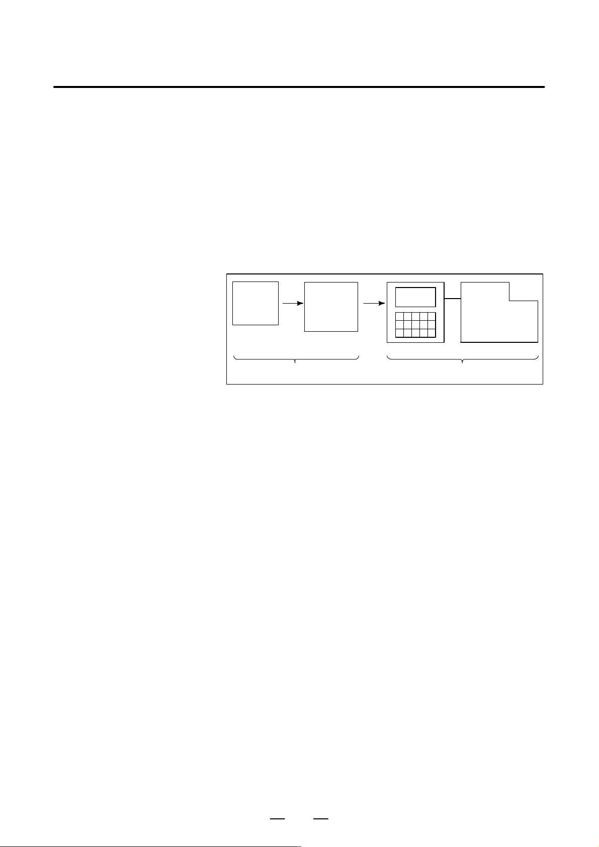
GENERAL1. GENERAL
B–64154EN/01
1.1
GENERAL FLOW OF OPERATION OF CNC MACHINE TOOL
When machining the part using the CNC machine tool, first prepare the
program, then operate the CNC machine by using the program.
1) First, prepare the program from a part drawing to operate the CNC
machine tool.
How to prepare the program is described in the Chapter II.
PROGRAMMING.
2) The program is to be read into the CNC system. Then, mount the
workpieces and tools on the machine, and operate the tools according
to the programming. Finally, execute the machining actually.
How to operate the CNC system is described in the Chapter III.
OPERATION.
Part
drawing
CHAPTER II PROGRAMMING CHAPTER III OPERATION
Part
programming
CNC
MACHINE TOOL
Before the actual programming, make the machining plan for how to
machine the part.
Machining plan
1. Determination of workpieces machining range
2. Method of mounting workpieces on the machine tool
3. Machining sequence in every cutting process
4. Cutting tools and cutting conditions
Decide the cutting method in every cutting process.
6
Page 31

B–64154EN/01
1.2
CAUTIONS ON READING THIS MANUAL
GENERAL
CAUTION
1 The function of an CNC machine tool system depends not
only on the CNC, but on the combination of the machine
tool, its magnetic cabinet, the servo system, the CNC, the
operator’s panels, etc. It is too difficult to describe the
function, programming, and operation relating to all
combinations. This manual generally describes these from
the stand–point of the CNC. So, for details on a particular
CNC machine tool, refer to the manual issued by the
machine tool builder, which should take precedence over
this manual.
2 Headings are placed in the left margin so that the reader can
easily access necessary information. When locating the
necessary information, the reader can save time by
searching though these headings.
3 This manual describes as many reasonable variations in
equipment usage as possible. It cannot address every
combination of features, options and commands that
should not be attempted.
If a particular combination of operations is not described, it
should not be attempted.
1. GENERAL
1.3
CAUTIONS ON V ARIOUS KINDS OF DATA
CAUTION
Machining programs, parameters, variables, etc. are stored
in the CNC unit internal non–volatile memory. In general,
these contents are not lost by the switching ON/OFF of the
power. However, it is possible that a state can occur where
precious data stored in the non–volatile memory has to be
deleted, because of deletions from a maloperation, or by a
failure restoration. In order to restore rapidly when this kind
of mishap occurs, it is recommended that you create a copy
of the various kinds of data beforehand.
7
Page 32

Page 33

II. PROGRAMMING
Page 34

Page 35

B–64154EN/01
1
GENERAL
PROGRAMMING
1) Punching is performered after positioning.
............. Punching function
1. GENERAL
Punching
Tool T01 Tool T02
2) Continuous, repetitive punching can be performed without halting the
pressing process after positioning
............. Nibbling function
3) By giving commands for block, it is possible to perform at multiple
positions in a given profile.
............. Pattern function
Punching
Program command
G00X––Y––T01 ;
X––T02 ;
Program command
M12 ;
G01X––Q–– ;
X––Y–– ;
:
:
M13 ;
d
#1
θ
In case of line at angle (G76)
This CNC supports the eight different patterns that will be used most
frequently.
11
#n
Program command
G76I––J––K–– ;
Page 36

PROGRAMMING1. GENERAL
B–64154EN/01
1.1
TOOL MOVEMENT ALONG WORKPIECE P ARTS FIGURE– INTERPOLATION
Explanations
D Tool movement along a
straight line
The tool moves along straight lines and arcs constituting the workpiece
parts figure (See II–4).
The function of moving the tool along straight lines and arcs is called the
interpolation.
Tool
Workpiece
Program
G01 X_ _ Y_ _ ;
X_ _ ;
D Tool movement along an
arc
Fig. 1.1 (a) T ool movement along a straight line
Program
G03X_ _Y_ _R_ _;
Tool
Workpiece
Fig. 1.1 (b) T ool movement along an arc
12
Page 37

B–64154EN/01
PROGRAMMING
1. GENERAL
Symbols of the programmed commands G01, G02, ... are called the
preparatory function and specify the type of interpolation conducted in
the control unit.
(a) Movement along straight line
G01 Y__;
X––Y––––;
Control unit
Interpolation
a)Movement
along straight
line
b)Movement
along arc
Fig. 1.1 (c) Interpolation function
(b) Movement along arc
G03X––Y––R––;
X axis
Y axis
Tool
movement
CAUTION
Some machines move tables instead of tools but this
manual assumes that tools are moved against workpieces.
13
Page 38

PROGRAMMING1. GENERAL
B–64154EN/01
1.2
FEED– FEED FUNCTION
Movement of the tool at a specified speed for cutting a workpiece is called
the feed.
mm/min
F
Workpiece
Table
Fig. 1.2 Feed function
Tool
Feedrates can be specified by using actual numerics. For example, to feed
the tool at a rate of 150 mm/min, specify the following in the program:
F150.0
The function of deciding the feed rate is called the feed function (See
II–5).
14
Page 39

B–64154EN/01
1.3
PART DRAWING AND TOOL MOVEMENT
PROGRAMMING
1. GENERAL
1.3.1
Reference Position (Machine–Specific Position)
A CNC machine tool is provided with a fixed position. Normally, tool
change and programming of absolute zero point as described later are
performed at this position. This position is called the reference position.
Reference point
Distance between reference point
and workpiece holder is intrinsically
determined according to machines.
End
locator
Workpiece holder
The distance between the
reference point and the end
locator is intrinsically
determined according to
machines.
Explanations
Fig. 1.3.1 Reference position
The tool can be moved to the reference position in two ways:
(1)Manual reference position return (See III–3.1)
Reference position return is performed by manual button operation.
(2)Automatic reference position return (See II–6)
In general, manual reference position return is performed first after the
power is turned on. In order to move the tool to the reference position
for tool change thereafter, the function of automatic reference position
return is used.
15
Page 40

1.3.2
Coordinate System on Part Drawing and Coordinate System Specified by CNC – Coordinate System
PROGRAMMING1. GENERAL
Z
Y
Program
Z
B–64154EN/01
Y
Explanations
D Coordinate system
X
Part drawing
Fig. 1.3.2 (a) Coordinate system
X
Coordinate system
CNC
Command
Tool
Z
Y
Workpiece
X
Machine tool
The following two coordinate systems are specified at different locations:
(See II–7)
(1)Coordinate system on part drawing
The coordinate system is written on the part drawing. As the program
data, the coordinate values on this coordinate system are used.
(2)Coordinate system specified by the CNC
The coordinate system is prepared on the actual machine tool table.
This can be achieved by programming the distance from the current
position of the tool to the zero point of the coordinate system to be set.
Y
230
300
Program
zero point
Fig. 1.3.2 (b) Coordinate system specified by the CNC
Present tool position
Distance to the zero point of a coordinate system to be set
X
16
Page 41

B–64154EN/01
PROGRAMMING
1. GENERAL
The positional relation between these two coordinate systems is
determined when a workpiece is set on the table.
The tool moves on the coordinate system specified by the CNC in
accordance with the command program generated with respect to the
coordinate system on the part drawing, and cuts a workpiece into a shape
on the drawing.
Therefore, in order to correctly cut the workpiece as specified on the
drawing, the two coordinate systems must be set at the same position.
D Methods of setting the
two coordinate systems
in the same position
When a workpiece is set on the table, these two coordinate systems lay
as follows:
The tool moves on the coordinate system specified by the CNC in
accordance with the command program generated with respect to the
coordinate system on the part drawing, and cut a workpiece into a shape
on the drawing.
Therefore, in order to correctly cut the workpiece as specified on the
drawing, the two coordinate systems must be set at the same position.
To set the two coordinate systems at the same position, when setting a
workpiece to be machined to general turret punch press, the workpiece is
held by the workpiece holders after positioning it by applying the end face
of the workpiece to the end locator and workpiece holders mounted on the
machine as illustrated below.
Y
Face B
Workpiece
X
End locator
Workpiece holder
Face A
Generally , the distance between the reference point and the and locator as
well as the distance between the reference point and the workpiece holders
are intrinsically determined according to machines, and they are separated
from each other by a fixed distance.
17
Page 42

1.3.3
How to Indicate Command Dimensions for Moving the Tool – Absolute, Incremental Commands
PROGRAMMING1. GENERAL
B–64154EN/01
Explanations
D Absolute coordinates
Coordinate values of command for moving the tool can be indicated by
absolute or incremental designation (See II–8.1).
The tool moves to a point at “the distance from zero point of the
coordinate system” that is to the position of the coordinate values.
Z
X
Command specifying movement from
point A to point B
Y
B(10,30,20)
G90 X10.0 Y30.0 Z20.0 ;
Coordinates of point B
Tool
A
D Incremental coordinates
Specify the distance from the previous tool position to the next tool
position.
Z
Tool
A
X=40
Y
Z=–10
B
X
Command specifying movement from
point A to point B
18
Y=–30
G91 X40.0 Y–30.0 Z–10.0
Distance and direction for
movement along each axis
;
Page 43

B–64154EN/01
PROGRAMMING
1. GENERAL
1.4
SELECTION OF T OOL USED FOR VARIOUS MACHINING – TOOL FUNCTION
Examples
When drilling, tapping, or the like, is performed, it is necessary to select
a suitable tool. When a number is assigned to each tool and the number
is specified in the program, the corresponding tool is selected.
04
05
06
07
03
08
02
Tool number
01
Turret
<When No.01 is assigned to a punching tool>
When the tool is stored at location 01 in the turret, the tool can be
selected by specifying T01. This is called the tool function (See II–11).
19
Page 44

PROGRAMMING1. GENERAL
B–64154EN/01
1.5
COMMAND FOR MACHINE OPERA TIONS – MISCELLANEOUS FUNCTION
During machining, on–off operation of work holder and clamper is
performed.
For this purpose, on–off operations of workholder and clamper should be
controlled.
Clamper
Work holder
The function of specifying the on–off operations of the components of the
machine is called the miscellaneous function. In general, the function is
specified by and M code.
20
Page 45

B–64154EN/01
PROGRAMMING
1. GENERAL
1.6
PROGRAM CONFIGURATION
A group of commands given to the CNC for operating the machine is
called the program. By specifying the commands, the tool is moved along
a straight line or an arc, or the spindle motor is turned on and off.
In the program, specify the commands in the sequence of actual tool
movements.
Block
Block
Tool movement sequence
Block
Program
Block
⋅
⋅
⋅
⋅
Block
Fig. 1.6 (a) Program configuration
A group of commands at each step of the sequence is called the block.
The program consists of a group of blocks for a series of machining. The
number for discriminating each block is called the sequence number, and
the number for discriminating each program is called the program
number (See II–13).
21
Page 46

PROGRAMMING1. GENERAL
B–64154EN/01
Explanations
D Block
D Program
The block and the program have the following configurations.
1 block
N ffff G ff Xff.f Yfff.f M ff S ff T ff ;
Sequence
number
Preparatory
function
Dimension word Miscel-
laneous
function
Fig. 1.6 (b) Block configuration
Spindle
function
Tool
function
End of
block
A block starts with a sequence number that identifies the block and ends
with an end–of–block code.
This manual indicates the end–of–block code by ; (LF in the ISO code and
CR in the EIA code).
;
Offff;
⋅
⋅
⋅
M30 ;
Fig. 1.6 (c) Program configuration
Program number
Block
Block
Block
⋅
⋅
⋅
End of program
Normally, a program number is specified after the end–of–block (;) code
at the beginning of the program, and a program end code (M02 or M30)
is specified at the end of the program.
22
Page 47

B–64154EN/01
PROGRAMMING
1. GENERAL
D Main program and
subprogram
When machining of the same pattern appears at many portions of a
program, a program for the pattern is created. This is called the
subprogram. On the other hand, the original program is called the main
program. When a subprogram execution command appears during
execution of the main program, commands of the subprogram are
executed. When execution of the subprogram is finished, the sequence
returns to the main program.
Main program
⋅
⋅
M98P1001
⋅
⋅
⋅
M98P1002
⋅
⋅
⋅
M98P1001
⋅
⋅
Subprogram #1
O1001
M99
Subprogram #2
O1002
Program for
hole #1
Program for
hole #2
⋅
M99
Hole #1
Hole #1
Hole #2
Hole #2
23
Page 48

1.7
TOOL FIGURE AND TOOL MOTION BY PROGRAM
Explanations
PROGRAMMING1. GENERAL
B–64154EN/01
D Machining using the side
of cutter – Cutter
compensation function
(See II–15.1, 15.2)
Because a cutter has a radius, the center of the cutter path goes around the
workpiece with the cutter radius deviated.
Cutter path using cutter
compensation
Machined part
figure
Workpiece
Cutter
If radius of cutters are stored in the CNC (Data Display and Setting : see
III–11), the tool can be moved by cutter radius apart from the machining
part figure. This function is called cutter compensation.
24
Page 49

B–64154EN/01
PROGRAMMING
1. GENERAL
1.8
TOOL MOVEMENT RANGE – STROKE
Limit switches are installed at the ends of each axis on the machine to
prevent tools from moving beyond the ends. The range in which tools can
move is called the stroke.
Table
Motor
Limit switch
Machine zero point
Specify these distances.
Tools cannot enter this area. The area is specified by data in memory or
a program.
Besides strokes defined with limit switches, the operator can define an
area which the tool cannot enter using a program or data in memory (see
Section III–11). This function is called stroke check.
25
Page 50

2
PROGRAMMING2. CONTROLLED AXES
CONTROLLED AXES
B–64154EN/01
26
Page 51

B–64154EN/01
2.1
CONTROLLED AXES
PROGRAMMING 2. CONTROLLED AXES
Item 0i–PC
No. of basic controlled axes 3 axes
Controlled axes expansion (total) Max. 4 axes
Basic simultaneously controlled axes 2 axes
Simultaneously controlled axes expansion Max. 4 axes
2.2
AXIS NAME
Limitations
D Default axis name
D Duplicate axis names
2.3
INCREMENT SYSTEM
The names of the two basic axes are fixed to X and Y, while the names of
additional axes can be set to any of A, B, C, U, V, W, and T.
Parameter No. 1020 is used to determine the name of each axis.
When this parameter is set to 0 or a character other than the valid
characters is specified, an axis name from 1 to 4 is assigned by default.
When a default axis name (1 to 4) is used, operation in the MEM mode,
MDI mode and RMT mode is disabled.
If a duplicate axis name is specified in the parameter, operation is enabled
only for the axis specified first.
If A, B, U, V and W is specified an axis name, the punch press macro
function is not available.
Name of
increment
system
IS–A
IS–B
Least input
increment
0.01mm
0.001inch
0.01deg
0.001mm
0.0001inch
0.001deg
Least command
increment
0.01mm
0.001inch
0.01deg
0.001mm
0.0001inch
0.001deg
Maximum
stroke
999999.99mm
99999.999inch
999999.99deg
99999.999mm
9999.9999inch
99999.999deg
Combined use of the inch system and the metric system is not allowed.
There are functions that cannot be used between axes with different unit
systems (circular interpolation, cutter compensation, etc.). For the
increment system, see the machine tool builder’s manual.
27
Page 52

PROGRAMMING2. CONTROLLED AXES
B–64154EN/01
2.4
MAXIMUM STROKE
Limitations
Maximum stroke = Least command increment 99999999
See 2.3 Incremen System.
D T axis is the axis for turret indexing.
D The least input increment is not provided for the turret axis. Neither
movement direction nor amount on the turret axis is commanded after
address T, but the tool number is commanded. The control system
moves the turret axis to the location being preset by a tool registering
screen according to the specified tool number , and selects the specified
tool.
28
Page 53

B–64154EN/01
3
3. PREPARATORY FUNCTION
PROGRAMMING
PREPARATORY FUNCTION (G FUNCTION)
A number following address G determines the meaning of the command
for the concerned block.
G codes are divided into the following two types.
Type Meaning
One–shot G code The G code is effective only in the block in which it is
specified.
Modal G code The G code is effective until another G code of the
same group is specified.
(Example )
G01 and G00 are modal G codes in group 01.
(G FUNCTION)
Explanations
G01X ;
Y ;
X ;
G00Y ;
1. When the clear state (bit 6 (CLR) of parameter No. 3402) is set at
power–up or reset, the modal G codes are placed in the states
described below.
(1) The modal G codes are placed in the states marked with as
indicated in Table 3.
(2) G20 and G21 remain unchanged when the clear state is set at
power–up or reset.(3)
For G22 and G23, G22 is set at power–up. However, G22 and G23
remain unchanged when the clear state is set at reset.
(4)The user can select G00 or G01 by setting bit 0 (G01) of parameter
No. 3402.
(5)The user can select G90 or G91 by setting bit 3 (G91) of parameter
No. 3402.
(6)The user can select G17, G18, or G19 by setting bit 1 (G18) and bit
1 (G19) of parameter No. 3402.
2. G codes other than G10 and G11 are one–shot G codes.
3. When a G code not listed in the G code list is specified, or a G code
that has no corresponding option is specified, alarm No. 010 is output.
4. Multiple G codes can be specified in the same block if each G code
belongs to a different group. If multiple G codes that belong to the
same group are specified in the same block, only the last G code
specified is valid.
5. G codes are indicated by group.
G01 is effective in this range.
29
Page 54

3. PREPARATORY FUNCTION
01
00
00
02
06
04
00
07
19
11
00
14
(G FUNCTION)
G code
G00 G00
G01 G01
G02 G02
G03 G03 Circular interpolation (CCW) / Helical interpolation (CCW)
G04 G04
G08 G08
G09 G09 Exact stop
G10 G10
G11 G11
G17 G17
G18 G18
G19 G19
G20 G20
G21 G21
G22 G22
G23 G23
G26 G26
G28 G50
G32 G32
G33 G33
G38 G38 Bending compensation X
G39 G39 Bending compensation Y
G40 G40
G41 G41
G42 G42 Cutter compensation right
G40.1
(G150)
G41.1
(G151)
G42.1
(G152)
G50 G34
G51 G35
G52 G93
G53 G53
G54 G54
G55 G55
G56 G56
G57 G57
G58 G58 Work coordinates system 5 selection
G59 G59 Work coordinates system 6 selection
G code Group Meaning
G40.1
(G150)
G41.1
(G151)
G42.1
(G152)
PROGRAMMING
T able 3 G code list (1/2)
Positioning (Rapid traverse)
Linear interpolation (Cutting feed)
Circular interpolation (CW) / Helical interpolation (CW)
Dwell
Advanced preview control
Programmable data input
Programmable data input mode cancel
XpYp plane Where Xp : X–axis or an axis parallel to it
ZpXp plane Y p : Y–axis or an axis parallel to it
YpZp plane Zp : Z–axis or an axis parallel to it
Input in inch
Input in inch
Stored stroke limit function on
Stored stroke limit function off
Bolt hole circle
Automatic reference point return
Automatic safety zone setting
Skip function
Cutter compensation cancel
Cutter compensation left
Normal direction control canceled
Left–side normal direction control turned on
Right–side normal direction control turned on
Scaling on
Scaling off
Local coordinate system setting
Machine coordinate system selection
Work coordinates system 1 selection
Work coordinates system 2 selection
Work coordinates system 3 selection
Work coordinates system 4 selection
B–64154EN/01
30
Page 55

B–64154EN/01
15
15
12
00
16
00
03
00
PROGRAMMING
T able 3 G code list (2/2)
G code MeaningGroupG code
G61 G61
G62 G62
G64 G64
G65 G95 00 Custom macro simple call
G66 G96
G67 G97
G68 G68
G69 G69
G70 G70
G72 G72
G73 G75
G74 G76
G75 G27 Automatic repositioning
G76 G28 Line at angle
G77 G29 Arc
G78 G36 Grid I
G79 G37 Grid II
G84 G84
G85 G85
G86 G66
G87 G67
G88 G78
G89 G79 Cut at angle
G90 G90
G91 G91
G92 G92
G98 G98
Exact stop mode
Automatic corner override
Continuous cutting mode
Custom macro modal call
Custom macro modal call cancel
Circular nibbling
Linear nibbling
Positioning & press off
Standard point command
Multi–piece machining command X
Multi–piece machining command Y
Coorrdinate rotating on
Coordinate rotating off
Share proof
Square
Radius
Absolute command
Incremental command
Coordinate system setting
Coordinate system setting (Multi–piece machining)
3. PREPARATORY FUNCTION
(G FUNCTION)
31
Page 56

4
PROGRAMMING4. INTERPOLATION FUNCTIONS
INTERPOLATION FUNCTIONS
B–64154EN/01
32
Page 57

B–64154EN/01
PROGRAMMING
4. INTERPOLATION FUNCTIONS
4.1
POSITIONING (G00)
Format
Explanations
The G00 command moves a tool to the position in the workpiece system
specified with an absolute or an incremental command at a rapid traverse
rate.
In the absolute command, coordinate value of the end point is
programmed.
In the incremental command the distance the tool moves is programmed.
IP
G00 _;
_: For an absolute command, the coordinates of an end
IP
position, and for an incremental commnad, the distance
the tool moves.
Either of the following tool paths can be selected according to bit 1 of
parameter LRP No. 1401.
D Nonlinear interpolation positioning
The tool is positioned with the rapid traverse rate for each axis
separately. The tool path is normally straight.
D Linear interpolation positioning
The tool path is the same as in linear interpolation (G01). The tool is
positioned within the shortest possible time at a speed that is not more
than the rapid traverse rate for each axis.
Start position
Linear interpolation positioning
End position
Non linear interpolation positioning
The rapid traverse rate in G00 command is set to the parameter No. 1420
for each axis independently by the machine tool builder. In the
posiitoning mode actuated by G00, the tool is accelerated to a
predetermined speed at the start of a block and is decelerated at the end
of a block. Execution proceeds to the next block after confirming the
in–position.
“In–position ” means that the feed motor is within the specified range.
This range is determined by the machine tool builder by setting to
parameter No. 1826.
33
Page 58

PROGRAMMING4. INTERPOLATION FUNCTIONS
B–64154EN/01
When G00X_Y_T ; is specified in a machine having a turret axis (T–axis),
the X and Y axes move to the specified positions at rapid traverse rate and
also the T–axis moves at the predetermined rapid traverse rate in such a
way as to select a specified tool number.
In a machine provided with a die angle index (C–axis), if “G00X_Y_ ; ”
is specified, the X, Y, and C axes move simultaneously at the
predetermined rapid traverse rate.
Refer to “C axis control” for the details. Since this control system treats
the turret punch press as a controlled system, the tool moves to the
commanded position as fast as possible for punching as the basic
principle.
Accordingly, the tool is positioned at rapid traverse, punching is done
after axis movement in the G00 mode, in principle.
Refer to “Punch function” for details.
The rapid traverse rate in the G00 command is set for each axis
independently by the machine tool builder (parameter No. 1420).
Accordingly , the rapid traverse rate cannot be specified in the address F.
In the positioning mode actuated by G00, the tool is accelerated to a
predetermined speed at the start of a block and is decelerated at the end
of a block. Execution proceeds to the next block after confirming the
in–position.
“In–position” means that the feed motor is within the specified range.
(This range is determined by the machine tool builder) (Parameter No.
1827)
CAUTION
For T– or C–axis command blocks, nonlinear interpolation
positioning is performed, even if linear interpolation
positioning is specified.
And, for block including G28 or G53 command, nonlinear
interpolation positioning is performed.
34
Page 59

B–64154EN/01
PROGRAMMING
4. INTERPOLATION FUNCTIONS
4.2
LINEAR INTERPOLATION (G01)
Format
Explanations
Tools can move along a line
IP
G01 _F_;
_:For an absolute command, the coordinates of an end point ,
IP
and for an incremental commnad, the distance the tool moves.
F_:Speed of tool feed (Feedrate)
A tools move along a line to the specified position at the feedrate
specified in F.
The feedrate specified in F is effective until a new value is specified. It
need not be specified for each block.
The feedrate commanded by the F code is measured along the tool path.
If the F code is not commanded, the feedrate is regarded as zero.
The feedrate of each axis direction is as follows.
G01ααββγγζζ
Feed rate of α axis direction :
Feed rate of Β axis direction :
Feed rate of Γ axis direction :
Feed rate of Ζ axis direction :
Ǹ
L + a2) b2) g2) z
Ff ;
a
Fa +
f
L
b
Fb+
f
L
g
Fg +
f
L
z
Fz+
f
L
2
The feed rate of the rotary axis is commanded in the unit of deg/min (the
unit is decimal point position).
When the straight line axis α(such as X, Y, or Z) and the rotating axisβ
(such as A, B, or C) are linearly interpolated, the feed rate is that in which
the tangential feed rate in the α and β cartesian coordinate system is
commanded by F(mm/min).
β–axis feedrate is obtained ; at first, the time required for distribution is
calculated by using the above fromula, then the β –axis feedrate unit is
changed to deg/min.
35
Page 60

PROGRAMMING4. INTERPOLATION FUNCTIONS
B–64154EN/01
A calcula;tion example is as follows.
G91 G01 X20.0B40.0 F300.0 ;
This changes the unit of the C axis from 40.0 deg to 40mm with metric
input. The time required for distribution is calculated as follows:
Examples
D Linear interpolation
Ǹ
202) 40
The feed rate for the C axis is
300
40
0.14907
2
0.14907 (min)8
8
268.3 degńmin
In simultaneous 3 axes control, the feed rate is calculated the same way
as in 2 axes control.
(G91) G01X200.0Y100.0F200.0 ;
Y axis
100.0
(End position)
Limitations
D Feedrate for the
rotation axis
(Start position)
200.00
X axis
D Punching (1–cycle pressing) is not performed in G01 mode.
D T code can’t be specified in G01 mode. If specified, an alarm (No.
4600) occurs.
However, when T code is specified independently and NMG (No.
16181#0) is set, an alarm does not occur.
G91G01C–90.0 G300.0 ;Feed rate of 300deg/min
(Start point)
90°
(End point)
Feedrate is 300 deg/min
36
Page 61

B–64154EN/01
PROGRAMMING
4. INTERPOLATION FUNCTIONS
4.3
CIRCULAR INTERPOLATION (G02, G03)
Format
The command below will move a tool along a circular arc.
Arc in the XpYp plane
G17
Arc in the ZpXp plane
G18
Arc in the Y pZpplane
G19
G02
G03
G02
G03
G02
G03
Xp_Yp_
Xp_ p_
Yp_ Zp_
I_ J_
R_
I_ K_
R_
J_ K_
R_
F_ ;
F_
F_
Table. 4.3 Description of the Command Format
Command Description
G17 Specification of arc on XpYp plane
G18 Specification of arc on ZpXp plane
G19 Specification of arc on Y pZp plane
G02 Circular Interpolation Clockwise direction (CW)
G03 Circular Interpolation Counterclockwise direction (CCW)
X
p_
Y
p_
Z
p_
I_ Xp axis distance from the start point to the center of an arc
J_ Yp axis distance from the start point to the center of an arc
Command values of X axis or its parallel axis
(set by parameter No. 1022)
Command values of Y axis or its parallel axis
(set by parameter No. 1022)
Command values of Z axis or its parallel axis
(set by parameter No. 1022)
with sign
with sign
k_ Zp axis distance from the start point to the center of an arc
with sign
R_ Arc radius with sign fixed to radius designation.
F_ Feedrate along the arc
37
Page 62

Explanations
PROGRAMMING4. INTERPOLATION FUNCTIONS
B–64154EN/01
D Direction of the circular
interpolation
D Distance moved on an
arc
D Distance from the start
point to the center of arc
“Clockwise”(G02) and “counterclockwise”(G03) on the XpYp plane
plane or YpZp plane) are defined when the XpYp plane is viewed
(Z
pXp
in the positive–to–negative direction of the Z
axis (Yp axis or Xp axis,
p
respectively) in the Cartesian coordinate system. See the figure below.
Yp Xp Zp
G18
G03
Zp
G03
G02
Yp
G19
G02
G17
G03
G02
Xp
The end point of an arc is specified by address Xp, Yp or Zp, and is
expressed as an absolute or incremental value according to G90 or G91.
For the incremental value, the distance of the end point which is viewed
from the start point of the arc is specified.
The arc center is specified by addresses I, J, and K for the Xp, Y p, and Zp
axes, respectively . The numerical value following I, J, or K, however, is
a vector component in which the arc center is seen from the start point,
and is always specified as an incremental value irrespective of G90 and
G91, as shown below.
I, J, and K must be signed according to the direction.
End point (x,y)
yx
x
Center
i
Start
point
j
End point (z,x)
z
Center
k
Start
point
i
I0,J0, and K0 can be omitted. When Xp, Yp , and Z
End point (y ,z)
z
y
j
Center
are omitted (the end
p
Start
point
k
point is the same as the start point) and the center is specified with I, J,
and K, a 360° arc (circle) is specified.
G02I; Command for a circle
If the difference between the radius at the start point and that at the
end point exceeds the value in a parameter (No.3410), an alarm (No.024)
occurs.
38
Page 63

B–64154EN/01
PROGRAMMING
4. INTERPOLATION FUNCTIONS
D Arc radius
The distance between an arc and the center of a circle that contains the arc
can be specified using the radius, R, of the circle instead of I, J, and K.
In this case, one arc is less than 180°, and the other is more than 180° are
considered. When an arc exceeding 180° is commanded, the radius must
be specified with a negative value. If Xp, Yp, and Zp are all omitted, if
the end point is located at the same position as the start point and when
R is used, an arc of 0° is programmed
G02R ; (The cutter does not move.)
For arc (1)(less than 180°)
G91 G02 XP60.0 YP20.0 R50.0 F300.0 ;
For arc (2)(greater than 180°)
G91 G02 X
60.0 YP20.0 R–50.0 F300.0 ;
P
(2)
r=50mm
Start point
Y
End point
(1)
r=50mm
D Feedrate
Limitations
X
The feedrate in circular interpolation is equal to the feed rate specified by
the F code, and the feedrate along the arc (the tangential feedrate of the
arc) is controlled to be the specified feedrate.
The error between the specified feedrate and the actual tool feedrate is
±2% or less. However, this feed rate is measured along the arc after the
cutter compensation is applied
If I, J, K, and R addresses are specified simultaneously, the arc specified
by address R takes precedence and the other are ignored.
If an axis not comprising the specified plane is commanded, an alarm is
displayed.
For example, if axis U is specified as a parallel axis to X axis when plane
XY is specified, an alarm (No.028)is displayed.
D Punching (1–cycle pressing) is not performed in G02 and G03 mode.
D If T command is specified in G02 and G03 mode, however, when T
code is specified independently and NMG (No. 16181#0) is set, an
alarm (No. 4600) doesn’t occur.
39
Page 64

Examples
PROGRAMMING4. INTERPOLATION FUNCTIONS
100
B–64154EN/01
Y axis
50R
60
40
0
90 120 140
60R
200
The above tool path can be programmed as follows ;
(1) In absolute programming
G92X200.0 Y40.0 ;
G90 G03 X140.0 Y100.0R60.0 F300.;
G02 X120.0 Y60.0R50.0 ;
or
G92X200.0 Y40.0 ;
G90 G03 X140.0 Y100.0I–60.0 F300.;
G02 X120.0 Y60.0I–50.0 ;
(2) In incremental programming
G91 G03 X–60.0 Y60.0 R60.0 F300.;
G02 X–20.0 Y–40.0 R50.0 ;
or
G91 G03 X–60.0 Y60.0 I–60.0 F300. ;
G02 X–20.0 Y–40.0 I–50.0 ;
X axis
40
Page 65

B–64154EN/01
PROGRAMMING
4. INTERPOLATION FUNCTIONS
4.4
SKIP FUNCTION (G33)
Format
Explanations
Linear interpolation can be commanded by specifying axial move
following the G33 command, like G01. If an external skip signal is input
during the execution of this command, execution of the command is
interrupted and the next block is executed.
The skip function is used when the end of machining is not programmed
but specified with a signal from the machine. It is used also for measuring
the dimensions of a workpiece.
IP
G33 _ ;
G33: One–shot G code (If is effective only in the block in
which it is specified)
The coordinate values when the skip signal is turned on can be used in a
custom macro because they are stored in the custom macro system
variable #5061 and #5062, as follows:
#5061 X axis coordinate value
#5062 Y axis coordinate value
WARNING
Disable feedrate override, dry run, and automatic
acceleration/deceleration (with parameter No. 6200 and
subsequent parameters) when the feedrate per minute is
specified, allowing for an error in the position of the tool
when a skip signal is input.
NOTE
If G33 command is issued while cutter compensation C is
applied, an P/S alarm of No.035 is displayed. Cancel the
cutter compensation with the G40 command before the G33
command is specified.
41
Page 66

Examples
D The next block to G33 is
an incremental
command
PROGRAMMING4. INTERPOLATION FUNCTIONS
G33 G91X100.0 F100;
Y50.0;
B–64154EN/01
Y50.0
D The next block to G33 is
an absolute command
for 1 axis
Skip signal is input here
Fig. 4.4 (a) The next block is an incremental command
G33 G90X200.00 F100;
Y100.0;
Skip signal is input here
100.0
50.0
Actual motion
Motion without skip signal
Y100.0
X200.0
D The next block to G33 is
an absolute command
for 2 axes
Actual motion
Motion without skip signal
Fig. 4.4 (b) The next block is an absolute command for 1 axis
G33 G90X200.0 F100;
X300.0 Y100.0;
Y
Skip signal is input here
100
100 200 300
Fig. 4.4 (c) The next block is an absolute command for 2 axes
(300,100)
Actual motion
Motion without skip signal
X
42
Page 67

B–64154EN/01
PROGRAMMING
4. INTERPOLATION FUNCTIONS
4.5
HIGH SPEED SKIP SIGNAL (G33)
Format
The skip function operates based on a high–speed skip signal (connected
directly to the NC; not via the PMC) instead of an ordinary skip signal.
In this case, up to eight signals can be input.
Delay and error of skip signal input is 0 – 2 msec at the NC side (not
considering those at the PMC side).
This high–speed skip signal input function keeps this value to 0.1 msec
or less, thus allowing high precision measurement.
For details, refer to the appropriate manual supplied from the machine
tool builder.
G33 IP_ ;
IP
G33: One–shot G code (If is effective only in the block in which it is
specified)
43
Page 68

4.6
HELICAL INTERPOLATION (G02, G03)
Format
PROGRAMMING4. INTERPOLATION FUNCTIONS
B–64154EN/01
Helical interpolation which moved helically is enabled by specifying up
to two other axes which move synchronously with the circular
interpolation by circular commands.
Synchronously with arc of XpY p plane
Explanations
G17
Synchronously with arc of ZpXp plane
G18
Synchronously with arc of Y pZp plane
G19
α,β:Any one axis where circular interpolation is not applied
G02
G03
G02
G03
G02
G03
Up to two other axes can be specified.
Xp_Yp_
Xp_Zp_
Yp_Zp_
I_J_
R_
I_K_
R_
J_K_
R_
α_(β_)F_;
α_(β_)F_;
α_(β_)F_;
.
The command method is to simply or secondary add a move command
axis which is not circular interpolation axes. An F command specifies a
feed rate along a circular arc. Therefore, the feed rate of the linear axis
is as follows:
Length of linear axis
F×
Length of circular arc
Determine the feed rate so the linear axis feed rate does not exceed any
of the various limit values.Bit 0 (HFC) of parameter No. 1404 can be used
to prevent the linear axis feedrate from exceeding various limit values.
Restrictions
Z
Tool path
YX
The feedrate along the circumference of two circular interpolated axes is the specified feedrate.
D Cutter compensation is applied only for a circular arc.
D T axis command and C axis command cannot be used in a block in
which a helical interpolation is commanded.
44
Page 69

B–64154EN/01
5
FEED FUNCTIONS
PROGRAMMING
5. FEED FUNCTIONS
45
Page 70

PROGRAMMING5. FEED FUNCTIONS
B–64154EN/01
5.1
GENERAL
D Feed functions
D Override
D Automatic acceleration/
deceleration
The feed functions control the feedrate of the tool. The following two feed
functions are available:
1. Rapid traverse
When the positioning command (G00) is specified, the tool moves at
a rapid traverse feedrate set in the CNC (parameter No. 1420).
2. Cutting feed
The tool moves at a programmed cutting feedrate.
Override can be applied to a rapid traverse rate or cutting feedrate using
the switch on the machine operator’s panel.
T o prevent a mechanical shock, acceleration/deceleration is automatically
applied when the tool starts and ends its movement (Fig. 5.1 (a)).
Rapid traverse rate
F
R
0
F
: Rapid traverse
R
rate
: Acceleration/
T
R
deceleration time
constant for rapid traverse rate
Time
T
R
Feed rate
F
C
0
T
C
Fig. 5.1 (a) Automatic acceleration/deceleration (example)
T
R
F
: Feedrate
C
: Acceleration/
T
C
T
C
deceleration time
constant for a cutting
feedrate
Time
46
Page 71

B–64154EN/01
PROGRAMMING
5. FEED FUNCTIONS
D Tool path in a cutting
feed
If the direction of movement changes between specified blocks during
cutting feed, a rounded–corner path may result (Fig. 5.1 (b)).
Y
Programmed path
Actual tool path
0
Fig. 5.1 (b) Example of T ool Path between Two Blocks
X
In circular interpolation, a radial error occurs (Fig. 5.1 (c)).
Y
0
Fig. 5.1 (c) Example of Radial Error in Circular Interpolation
∆r:Error
Programmed path
Actual tool path
r
X
The rounded–corner path shown in Fig. 5.1 (b) and the error shown in
Fig. 5.1 (c) depend on the feedrate. So, the feedrate needs to be controlled
for the tool to move as programmed.
47
Page 72

5.2
RAPID TRAVERSE
Format
PROGRAMMING5. FEED FUNCTIONS
IP
G00 _ ;
G00 : G code (group 01) for positioning (rapid traverse)
_; Dimension word for the end point
IP
B–64154EN/01
Explanations
5.2.1
Rapid T raverse Rate by F Command
The positioning command (G00) positions the tool by rapid traverse and
punching is performed. In rapid traverse, the next block is executed after
the specified feedrate becomes 0 and the servo motor reaches a certain
range set by the machine tool builder (in–position check).
A rapid traverse rate is set for each axis by parameter No. 1420, so no rapid
traverse feedrate need be programmed.
The following overrides can be applied to a rapid traverse rate with the
switch on the machine operator’s panel: 25, 50, 75, 100%
Each axis rapid traverse rate of rapid traverse command (G00) are set
independently to parameter by machine tool builders.
Whereas, by setting parameter G0F (No. 16050#0) to 1, the rapid traverse
rate of X and Y axes to rapid traverse command (G00) can be designated
by F code. Refer to the manual issued by a machine tool builder for this
function.
There are following specifications notices for this function.
1) The feedrate specified by F code is the each axis rapid traverse rate of
X and Y axes.
2) 4-step rapid traverse override can be applied to the rapid traverse rate
designated by F code, using signals (ROV2, ROV1) from the machine
side.
3) When axial move of rapid traverse (G00) is specified in the tape,
memory and MDI modes, the rapid traverse rate may not specified by
F code or when the speed command is 0, an alarm (No. 011) occurs.
4) In circular nibbling (G68), linear nibbling (G69) and nibbling by M
function, the speed to nibbling pitch after the first punch point
corresponds to the rapid traverse rate preset by the parameter (No.
1420).
5) F1-digit function for programmable rapid traverse override is
ineffective.
6) When the rapid traverse rate designated by F code exceeds the speed
preset by a parameter (set by a machine tool builder), it is clamped to
the speed preset by the parameter (No. 1420).
48
Page 73

B–64154EN/01
5.2.2
Rapid Traverse Override
PROGRAMMING
5. FEED FUNCTIONS
In the automatic operation, the rapid traverse override is applied to the
rapid traverse rate by the switch on the machine operator’s panel or
F1-digit command (See Subsection 5.2.3).
Either rapid traverse override being set by the switch on the machine
operator’s panel or rapid traverse override being set by F1-digit
command, whichever is lower, becomes effective.
Examples1
Examples2
One digit
F command
F1 100% 100% 100%
F2 75% 75% 100%
F3 50%
F4
Rapid traverse override switch on
machine operator’s panel
25%
X-axis,
Y-axis
50%
25%
T-axis,
C-axis
50%
50%
If F3 command is given when the switch on the machine operator’s panel
is set to 100%, the rapid traverse override of the X and Y axes becomes
50%, and also that of T-axis and C axis becomes 50%.
If F1 command is given when the switch on the machine operator’s panel
is set to 25%, the rapid traverse override of the X and Y axes becomes
25%, while that of T-axis and C axis becomes 50%.
In manual operation mode, the rapid traverse override by the switch on
the machine operator’s panel and by one-digit F command is inef fective.
WARNING
For the T-axis and C axis, the rapid traverse override can
always be set to 100% by setting a parameter TCO (No.
16052#1).
49
Page 74

PROGRAMMING5. FEED FUNCTIONS
One-digit F command
B–64154EN/01
5.2.3
F1-digit (Programmable Rapid T raverse Override)
By specifying one-digit number from 1 to 4 following F , and override can
be applied to the rapid traverse rate in automatic operation.
Rapid traverse override
X axis, Y axis T axis, C axis
F1 100% 100%
F2 75% 100%
F3 50% 50%
F4 25% 50%
An override can be applied to the rapid traverse rate by the switch on the
machine operator’s panel as well as by F1-digit command in automatic
operation.
Either rapid traverse override being set by the switch or the rapid traverse
override being set by F1-digit command, whichever lower, becomes
effective (see 5.2.2) .
WARNING
1 For the T and C axis, the override can always be set to 100%
by setting a parameter TCO (No. 16052#1) .
2 F0 is equivalent to F1, while F5 to F9 are equivalent to F4.
3 When power is turned on, the machine is placed to the F1
command state.
If parameter CLR (No. 3402#6) is set to 1, this F1 state is
obtained after depressing the reset button. If CLR is set to
0, the state remains unchanged as before reset.
50
Page 75

B–64154EN/01
PROGRAMMING
5. FEED FUNCTIONS
5.3
CUTTING FEED
Format
Explanations
D Tangential speed
constant control
Feedrate of linear interpolation (G01), circular interpolation (G02, G03),
etc. are commanded with numbers after the F code.
In cutting feed, the next block is executed so that the feedrate change from
the previous block is minimized.
Feed per minute
F_ ; Feedrate command (mm/min or inch/min)
Cutting feed is controlled so that the tangential feedrate is always set at
a specified feedrate.
YY
End point
F
Start
point
F
D Feed per minute
Start
point
Linear interpolation
Fig. 5.3 (a) T angential feedrate (F)
Center
X
Circular interpolation
End point
X
The amount of feed of the tool per minute is to be directly specified by
setting a number after F.
An override from 0% to 254% (in 1% steps) can be applied to feed per
minute with the switch on the machine operator’s panel. For detailed
information, see the appropriate manual of the machine tool builder.
Feed amount per minute
(mm/min or inch/min)
Tool
Workpiece
Table
51
Fig. 5.3 (b) Feed per minute
Page 76

PROGRAMMING5. FEED FUNCTIONS
B–64154EN/01
WARNING
Cutting feed is invalid for the turret axis (T–axis) and C–axis.
T–axis and C–axis commands, therefore, cannot be
specified in linear interpolation (G01) mode and circular
interpolation (G02, G03) mode.
However, when the parameter CIP (No.16360#5) is set to
1, C–axis can be specified.
D Cutting feedrate clamp
A common upper limit can be set on the cutting feedrate along each axis
with parameter No. 1422. If an actual cutting feedrate (with an override
applied) exceeds a specified upper limit, it is clamped to the upper limit.
Parameter No. 1430 can be used to specify the maximum cutting feedrate
for each axis only for linear interpolation and circular interpolation.
When the cutting feedrate along an axis exceeds the maximum feedrate
for the axis as a result of interpolation, the cutting feedrate is clamped to
the maximum feedrate.
NOTE
An upper limit is set in mm/min or inch/min. CNC calculation
may involve a feedrate error of ±2% with respect to a
specified value. However, this is not true for
acceleration/deceleration. To be more specific, this error is
calculated with respect to a measurement on the time the
tool takes to move 500 mm or more during the steady state:
52
Page 77

B–64154EN/01
Auto–
ic c
PROGRAMMING
5. FEED FUNCTIONS
5.4
CUTTING FEEDRATE CONTROL
Function name
Exact stop
Exact stop
Cutting mode
Automatic override for
mat
inner corners
Internal circular cutting
feedrate change
Cutting feedrate can be controlled, as indicated in Table 5.4.
T able 5.4 Cutting Feedrate Control
G code V alidity of G code Description
G09
G61
G64
G62
G62
This function is valid for specified
blocks only.
Once specified, this function is valid
until G62 or G64 is specified.
Once specified, this function is valid
until G61 or G62 is specified.
Once specified, this function is valid
until G61 or G64 is specified.
This function is valid in the cutter
compensation mode, regardless of
the G code.
The tool is decelerated at the end point of
a block, then an in–position check is
made. Then the next block is executed.
The tool is decelerated at the end point of
a block, then an in–position check is
made. Then the next block is executed.
The tool is not decelerated at the end point
of a block, but the next block is executed.
When the tool moves along an inner corner during cutter compensation, override
is applied to the cutting feedrate to suppress the amount of cutting per unit of time
so that a good surface finish can be produced.
The internal circular cutting feedrate is
changed.
Format
NOTE
1 The purpose of in–position check is to check that the servo
motor has reached within a specified range (specified with
a parameter by the machine tool builder). When parameter
NCI (No. 1601#5) is set tool, in–position check is not
executed.
2 Inner corner angle θ: 2°
< θ x α x 178°
(α is a set value)
Workpiece
θ
Tool
Exact stop G09 _ ;
Cutting mode G64 ;
Automatic corner override G62 ;
IP
G61 ;
53
Page 78

5.4.1
Exact Stop (G09, G61) Cutting Mode (G64)
PROGRAMMING5. FEED FUNCTIONS
B–64154EN/01
Explanations
The inter–block paths followed by the tool in the exact stop mode and
cutting mode are different (Fig. 5.4.1).
Y
(2)
(1)
0
Fig. 5.4.1 Example of Tool Paths from Block (1) to Block (2)
Position check
Tool path in the exact stop mode
Tool path in the cutting mode
X
WARNING
The cutting mode (G64 mode) is set at power–on or system
clear.
54
Page 79

B–64154EN/01
PROGRAMMING
5. FEED FUNCTIONS
5.4.2
Automatic Corner Override
This function enables producing a smooth cutting surface by decelerating
tool movement automatically between an inside corner and an inside arc
to reduce the load on the cutter during cutter compensation.
5.4.2.1
Inside–corner Override (G62)
Explanations
D Override condition
1. Straight line–straight line 2. Straight line–arc
When G62 is specified, and the tool path with cutter compensation
applied forms an inner corner, the feedrate is automatically overridden
at both ends of the corner.
There are four types of inner corners (Fig. 5.4.2.1 (a)).
xθxθpx178_ in Fig. 5.4.2.1 (a)
2_
θp is a value set with parameter No. 1711. When θ is approximately
equal to
θp, the inner corner is determined with an error of 0.001_ or
less.
:Tool
:Programmed path
:Cutter center path
θ
3. Arc–straight line 4. Arc–arc
θ
Fig. 5.4.2.1 (a) Inner corner
θ
θ
55
Page 80

PROGRAMMING5. FEED FUNCTIONS
B–64154EN/01
WARNING
When the block before a corner is a start–up block, or the
block after a corner includes G41 or G42, the feedrate is not
overridden. The feedrate override function is disabled when
the offset value is 0.
Override range
When a corner is determined to be an inner corner, the feedrate is
overridden before and after the inner corner. The distances Ls and Le,
where the feedrate is overridden, are distances from points on the cutter
center path to the corner (Fig. 5.4.2.1 (b), Fig. 5.4.2.1 (c), Fig. 5.4.2.1 (d)).
Ls and Le are set with parameter Nos. 1713 and 1714.
Programmed path
Le
a
Cutter center path
The feedrate is overridden from point a to point b.
Fig. 5.4.2.1 (b) Override Range (Straight Line to Straight Line)
Ls
b
When a programmed path consists of two arcs, the feedrate is overridden
if the start and end points are in the same quadrant or in adjacent quadrants
(Fig. 5.4.2.1 (c)).
Le
Ls
a
Cutter center path
The feedrate is overridden from point a to b.
Fig. 5.4.2.1 (c) Override Range (Arc to Arc)
Programmed path
b
Regarding program (2) of an arc, the feedrate is overridden from point a
to point b and from point c to point d (Fig. 5.4.2.1 (d)).
56
Page 81

B–64154EN/01
PROGRAMMING
c
5. FEED FUNCTIONS
Programmed path
d a
LsLebLs Le
(2)
Override value
Restrictions
D Pre–interpolation
acceleration/deceleration
D Start–up or G41 and G42
D Offset data
5.4.2.2
Internal Circular Cutting Feedrate Change
Tool
Fig. 5.4.2.1 (d) Override Range (Straight Line to Arc, Arc to Straight Line)
Cutter center path
An override value is set with parameter No. 1712. An override value is
valid even for dry run and F1–digit specification.
In the feed per minute mode, the actual feedrate is as follows:
F × (automatic override for inner corners) × (feedrate override)
The inside–corner override function is disabled during pre–interpolation
acceleration/deceleration.
The inside–corner override function is disabled if a block before the
corner is a start–up block for cutter compensation or a block after the
corner contains G41 or G42.
The inside–corner override function is disabled if the offset data is 0.
For internally offset circular cutting, the feedrate on a programmed path
is set to a specified feedrate (F) by specifying the circular cutting feedrate
with respect to F, as indicated below (Fig. 5.4.2.2). This function is valid
in the cutter compensation mode, regardless of the G62 code.
Rc
F
Rp
Rc : Cutter center path radius
Rp : Programmed radius
It is also valid for the dry run and the one–digit F command.
Programmed path
Cutter center
Rc
Rp
Fig. 5.4.2.2 Internal circular cutting feedrate change
57
path
Page 82

PROGRAMMING5. FEED FUNCTIONS
If Rc is much smaller than Rp, Rc/Rp80; the tool stops. A minimum
deceleration ratio (MDR) is to be specified with parameter No. 1710.
When Rc/Rp
WARNING
When internal circular cutting must be performed together
with automatic override for inner corners, the feedrate of the
tool is as follows:
xMDR, the feedrate of the tool is (F×MDR).
Rc
F
(automatic override for the inner corners)
Rp
× (feedrate override)
B–64154EN/01
5.4.3
Automatic Corner Deceleration
5.4.3.1
Corner deceleration according to the corner angle
This function automatically controls the feedrate at a corner according to
the corner angle between the machining blocks or the feedrate difference
between the blocks along each axis.
This function is effective when ACD, bit 6 of parameter No. 1601, is set
to 1, the system is in G64 mode (machining mode), and a cutting–feed
block (block A) is followed by another cutting–feed block (block B).
The feedrate between machining blocks is controlled according to the
corner angle between the blocks or the feedrate difference between the
blocks along each axis. These two methods can be switched with CSD,
bit 4 of parameter No. 1602.
This function decelerates the feedrate when the angle between blocks A
and B on the selected plane is smaller than the angle specified in parameter
No. 1740. The function executes block B when the feedrates along both
the first and second axes are smaller than the feedrate specified in
parameter No. 1741. In this case, the function determines that the number
of accumulated pulses is zero.
58
Page 83

B–64154EN/01
Explanations
PROGRAMMING
5. FEED FUNCTIONS
D Flowchart for feedrate
control
The flowchart for feedrate control is shown below.
START
Is the corner angle smaller than
the angle specified in parameter
No. 1740?
Yes
Are the feedrates along the X–
and Y–axes smaller than that
specified in parameter No. 1741?
Yes
The number of accumulated
pulses is determined to be zero
and block B is executed
No
No
Further decelerates the
feedrate in block A
D Feedrate and time
END
When the corner angle is smaller than the angle specified in the
parameter, the relationship between the feedrate and time is as shown
below. Although accumulated pulses equivalent to the hatched area
remain at time t, the next block is executed because the feedrate of the
automatic acceleration/deceleration circuit is smaller than the
parameter–set value. This function is effective only for movement on
the selected plane.
Feedrate V
Block A
Parameter–set feedrate
t
Block B
Time t
59
Page 84

PROGRAMMING5. FEED FUNCTIONS
B–64154EN/01
D Acceleration/
deceleration before
interpolation
D Angle between two
blocks
When acceleration/deceleration before interpolation is effective, the
relationship between the feedrate and time is as shown below. When the
angle between blocks A and B on the selected plane is smaller than the
angle specified in parameter No. 1740, and the feedrates specified in
blocks A and B are larger than that specified in parameter No. 1777, the
feedrate is decelerated to the parameter–set value in block A, and
accelerated to the feedrate specified in block B. The acceleration depends
on the parameter for acceleration/deceleration before interpolation.
Feedrate
Block A
Parameter–set feedrate
(parameter No. 1777)
Block B
Time
The angle between two blocks (blocks A and B) is assumed to be angle
θ, as shown below.
1. Between linear movements
θ
D Selected plane
D Corner roundness
2. Between linear and circular movements
(angle between the linear movement
and tangent to the circular movement)
θ
θ
3. Between circular movements
(angle between the tangents to
the circular movements)
θ
The machining angle is compared with the angle specified in parameter
No. 1740 for movements on the selected plane only. Machining feedrates
are compared with that specified in parameter No. 1741 for movement
along the first and second axes on the selected plane only. This means,
when movement occurs along three or more axes, only that movement
along the first and second axes on the selected plane is considered.
Corner roundness is determined by the angle and feedrate specified in
parameter Nos. 1740 and 1741. To always make a sharp corner, set the
angle to zero and the feedrate to 180000 (equivalent to 180 degrees).
D Exact stop
When G90 (exact stop) is specified, exact stop is performed irrespective
of the angle and feedrate specified in parameter Nos. 1740 and 1741.
60
Page 85

B–64154EN/01
PROGRAMMING
5. FEED FUNCTIONS
D Advanced preview
control
Limitations
5.4.3.2
Corner deceleration according to the feedrate difference between blocks along each axis
Those parameters related to automatic corner deceleration in advanced
preview control mode are shown below.
Advanced
preview
control mode
Parameter description
Switching the methods for automatic corner deceleration
Lower limit of feedrate in automatic corner deceleration based on the angle
Limit angle in corner deceleration based on the
angle
Normal
mode
1602#4 1602#4
1777 1778
1740 1779
This function cannot be enabled for a single block or during dry run.
This function decelerates the feedrate when the difference between the
feedrates at the end point of block A and the start point of block B along
each axis is larger than the value specified in parameter No. 1781. The
function executes block B when the feedrates along all axes are smaller
than the feedrate specified in parameter No. 1741. In this case, the
function determines that the number of accumulated pulses is zero.
Explanations
D Flowchart for feedrate
control
The flowchart for feedrate control is shown below.
START
Is the feedrate difference between
blocks along each axis larger than
the value specified in parameter
No. 1781?
Yes
Are the feedrates along all axes
smaller than that specified in
parameter No. 1741?
Yes
The number of accumulated pulses
is determined to be zero and block
B is executed
No
No
Further decelerates the
feedrate in block A
61
END
Page 86

PROGRAMMING5. FEED FUNCTIONS
B–64154EN/01
D Feedrate and time
D Acceleration /
deceleration before
interpolation
When the feedrate difference between blocks along each axis is larger than
the value specified in parameter No. 1781, the relationship between the
feedrate and time is as shown below. Although accumulated pulses
equivalent to the hatched area remain at time t, the next block is executed
because the feedrate of the automatic acceleration/deceleration circuit is
smaller than the feedrate specified in parameter No. 1741.
Feedrate V
Block A
Parameter–set feedrate
t
Block B
Time t
When acceleration/deceleration before interpolation is effective, the
relationship between the feedrate and time is as described below.
When the feedrate difference between blocks A and B along each axis is
larger than the value specified in parameter No. 1780, the feedrate is
decelerated to the corner feedrate calculated from the feedrate dif ference
along each axis.
Let the feedrate be F. Compare the feedrate difference along each axis
(Vc[X], Vc[Y], ...) with the value specified in parameter No. 1780, Vmax.
When the difference exceeds Vmax, calculate R as shown below.
R=
Vc
Vmax
Find the maximum value for R among the calculated values for the axes.
Let it be Rmax. Then, the corner feedrate can be obtained as follows:
Fc=F*
(Example)
1
Rmax
N1
N2
N1 G01 G91 X80. Y20. F3000 ;
N2 X20. Y80. ;
When this movement is specified, the feedrate along each axis is as shown
in the next figure.
Rmax=
F*
Vc[X(Y)]
Vmax
1
Rmax
From the figure, it can be seen that the feedrate differences along the X–
and Y–axes (Vc[X] and Vc[Y]) exceed Vmax. Calculate Rmax to get Fc.
When the feedrate is decelerated to Fc at the corner, the feedrate difference
along each axis do not exceed Vmax.
62
Page 87

B–64154EN/01
PROGRAMMING
5. FEED FUNCTIONS
Without corner deceleration
With corner deceleration
Feedrate along
the X–axis
Feedrate along
the Y–axis
Feedrate along
the tangent
at the corner
1
F*
Rmax
Vc [X]
Vmax
Vc [Y]
D Setting the allowable
feedrate difference along
each axis
D Checking the feedrate
difference
D Exact stop
D Override
N1 N2 t
The allowable feedrate difference can be specified for each axis in
parameter No. 1783.
The feedrate difference is also checked during dry–run operation or
during deceleration caused by an external signal, using feedrate
commands specified in a program.
When G90 (exact stop) is specified, exact stop is performed irrespective
of the parameter settings.
If an override is changed during operation, the feedrate difference will
not be checked correctly.
63
Page 88

PROGRAMMING5. FEED FUNCTIONS
B–64154EN/01
D Advanced preview
control
Limitations
Parameters related to automatic corner deceleration in advanced
preview control mode are shown below.
Advanced
preview
control mode
Parameter description
Switching the methods for automatic
corner deceleration
Allowable feedrate difference (for all axis)
in automatic corner deceleration based on
the feedrate difference
Allowable feedrate difference (for each
axis) in automatic corner deceleration
based on the feedrate difference
Normal
mode
1602#4 ←
1780 ←
1783 ←
This function is not effective for a single block.
64
Page 89

B–64154EN/01
s
5.5
DWELL (G04)
Format
PROGRAMMING
Dwell G04 X_ ; or G04 P_ ;
X_ : Specify a time (decimal point permitted)
P_ : Specify a time (decimal point not permitted)
5. FEED FUNCTIONS
Explanations
By specifying a dwell, the execution of the next block is delayed by the
specified time. In addition, a dwell can be specified to make an exact
check in the cutting mode (G62 mode).
When neither P nor X is specified, exact stop is performed.
T able 5.5 (a) Command value range of the dwell time (Command by X)
Increment system Command value range Dwell time unit
IS–A 0.01 to 999999.99
IS–B 0.001 to 99999.999
T able 5.5 (b) Command value range of the dwell time (Command by P)
Increment system
IS–A 1 to 99999999 0.01 s
IS–B 1 to 99999999 0.001 s
Command value range Dwell time unit
65
Page 90

6
PROGRAMMING6. REFERENCE POSITION
REFERENCE POSITION
B–64154EN/01
66
Page 91

B–64154EN/01
6.1
REFERENCE POSITION RETURN
PROGRAMMING
6. REFERENCE POSITION
D Reference position
The reference position is a certain fixed point on the machine. It is defined
as the point, to which a tool can be moved easily by the reference point
return.
When setting a workpiece to be machined to general turret punch press,
the workpiece is held by the workpiece holders after positioning it by
applying the end face of the workpiece to the end locator and workpiece
holders mounted on the machine as illustrated below.
Y
Face
B
End locator
Workpiece holder
Workpiece
X
Face A
Face B
Apply face B to the end locator.
End locator
Apply face A to workpiece holder.
Workpiece
Fig. 6.1 (a)
Face A
Workpiece holder
Generally , the distance between the reference position and the end locator
as well as the distance between the reference position and the workpiece
holders are intrinsically determined according to machines, and they are
separated from each other by a fixed distance.
67
Page 92

End
locator
PROGRAMMING6. REFERENCE POSITION
Distance between reference position
and workpiece holder is intrinsically
determined according to machines.
Workpiece holder
The distance between the reference position
and the end locator is intrinsically determined
according to machines.
B–64154EN/01
Reference
position
Fig. 6.1 (b)
Accordingly, if the start point is at the reference position and the point
located at the left lower side of the workpiece is presumed as the zero point
of the workpiece coordinate system, tool position at the start point can be
taught to NC as a position in the workpiece coordinate system by giving
the following command at the initial stage of programming.
G92X x
where, x
Y yR ;
R
: Distance from end locator to reference position along X-axis
R
: Distance from workpiece holder to reference position along
y
R
Y-axis
68
Page 93

B–64154EN/01
PROGRAMMING
6. REFERENCE POSITION
D Reference position
return and movement
from the reference
position
Format
D Reference position
return
T ools are automatically moved to the reference position. When reference
position return is completed, the lamp for indicating the completion of
return goes on.
Reference position return A→R
R (Reference position)
A (Start position for reference position return)
Fig. 6.1 (c) Reference position return
G28_ ;
Reference position return
Explanations
D Reference position
return (G28)
Limitations
D Status the machine lock
being turned on
D First return to the
reference position after
the power has been
turned on (without an
absolute position
detector)
D Lighting the lamp when
the programmed position
does not coincide with
the reference position
Reference positions are performed at the rapid traverse rate of each axis.
When using this command, usually cancel the cutter compensation.
Example G28 M30;
The lamp for indicating the completion of return does not go on when the
machine lock is turned on, even when the tool has automatically returned
to the reference position.
When the G28 command is specified when manual return to the reference
position has not been performed after the power has been turned on, the
movement from the intermediate point is the same as in manual return to
the reference position.
In this case, the tool moves in the direction for reference position return
specified in parameter ZMIx (bit 5 of No. 1006). Therefore the specified
intermediate position must be a position to which reference position
return is possible.
When the machine tool system is an inch system with metric input, the
reference position return lamp may also light up even if the programmed
position is shifted from the reference position by 1
µ. This is because the
least input increment of the machine tool system is smaller than its least
command increment.
Reference
D Manual reference
position return
See III–3.1.
69
Page 94

7
PROGRAMMING7. COORDINATE SYSTEM
COORDINATE SYSTEM
By teaching the CNC a desired tool position, the tool can be moved to the
position. Such a tool position is represented by coordinates in a
coordinate system. Coordinates are specified using program axes.
When three program axes, the X–axis, Y–axis, and Z–axis, are used,
coordinates are specified as follows:
X_Y_Z_
This command is referred to as a dimension word.
B–64154EN/01
Z
25.0
Y
50.0
40.0
X
Fig. 7 Tool position specified by X40.0Y50.0Z25.0
Coordinates are specified in one of following three coordinate systems:
(1)Machine coordinate system
(2)Workpiece coordinate system
(3)Local coordinate system
The number of the axes of a coordinate system varies from one machine
to another. So, in this manual, a dimension word is represented as IP_.
70
Page 95

B–64154EN/01
PROGRAMMING
7. COORDINATE SYSTEM
7.1
MACHINE COORDINATE SYSTEM
Format
Explanations
D Selecting a machine
coordinate system (G53)
The point that is specific to a machine and serves as the reference of the
machine is referred to as the machine zero point. A machine tool builder
sets a machine zero point for each machine.
A coordinate system with a machine zero point set as its origin is referred
to as a machine coordinate system.
A machine coordinate system is set by performing manual reference
position return after power–on (see III–3.1). A machine coordinate
system, once set, remains unchanged until the power is turned off.
IP
G53 _ ;
_ : Absolute dimension word
IP
When a command is specified based on a machine coordinate system, the
tool moves by rapid traverse. G53, which is used to select a machine
coordinate system, is a one–shot G code; that is, it is valid only in the
block in which it is specified. The absolute command (G90) is valid. If
the incremental command (G91) is specified, G53 is not executed. When
the tool is to be moved to a machine–specific position such as a tool
change position, program the movement in a machine coordinate system
based on G53.
Limitations
D Cancel of the
compensation function
D G53 specification
immediately after
power–on
When the G53 command is specified, cancel the cutter compensation, and
tool offset.
Since the machine coordinate system must be set before the G53
command is specified, at least one manual reference position return or
automatic reference position return by the G28 command must be
performed after the power is turned on. This is not necessary when an
absolute–position detector is attached.
71
Page 96

PROGRAMMING7. COORDINATE SYSTEM
B–64154EN/01
7.2
WORKPIECE COORDINATE SYSTEM
7.2.1
Setting a Workpiece Coordinate System
A coordinate system used for machining a workpiece is referred to as a
workpiece coordinate system. A workpiece coordinate system is to be set
with the NC beforehand (setting a workpiece coordinate system).
A machining program sets a workpiece coordinate system (selecting a
workpiece coordinate system).
A set workpiece coordinate system can be changed by shifting its origin
(changing a workpiece coordinate system).
A workpiece coordinate system can be set using one of three methods:
(1) Method using G92
A workpiece coordinate system is set by specifying a value after G92
in the program.
(2) Automatic setting
If bit 0 of parameter No. 1201 is set beforehand, a workpiece
coordinate system is automatically set when manual reference
position return is performed (see Part III–3.1.).
(3) Method using G54 to G59
After six workpiece coordinate systems are set from the MDI panel,
the program commands G54 to G59 are used to select which
workpiece coordinate system is used (see III–11.4.7). Before
specifying the absolute command, use one of the above methods to
establish the workpiece coordinate system.
Format
D Setting a workpiece
coordinate system by G92
Explanations
Examples
(G90) G92 _IP
A workpiece coordinate system is set so that a point on the tool, such as
the tool tip, is at specified coordinates.
Cutter compensation is cancelled temporarily with G92.
M.S and T code cannot be specified in G92 block.
Y
1016.0
Meet the programming start
point with a center of the tool
and command G92 at the start
of program.
G92X1270.0Y1016.0 ;
72
1270.0
X
Page 97

B–64154EN/01
PROGRAMMING
7. COORDINATE SYSTEM
7.2.2
Selecting a Workpiece Coordinate System
Examples
The user can choose from set workpiece coordinate systems as described
below . (For information about the methods of setting, see Section 7.2.1.)
(1) Selecting a workpiece coordinate system set by G92 or automatic
workpiece coordinate system setting
Once a workpiece coordinate system is selected, absolute commands
work with the workpiece coordinate system.
(2) Choosing from six workpiece coordinate systems set using the
MDI panel
By specifying a G code from G54 to G59, one of the workpiece
coordinate systems 1 to 6 can be selected.
G54 Workpiece coordinate system 1
G55 Workpiece coordinate system 2
G56 Workpiece coordinate system 3
G57 Workpiece coordinate system 4
G58 Workpiece coordinate system 5
G59 Workpiece coordinate system 6
Workpiece coordinate system 1 to 6 are established after reference
position return after the power is turned on. When the power is turned
on, G54 coordinate system is selected.
G90 G55 G00 X40.0 Y100.0 ;
Y
Workpiece coordinate system 2 (G55)
100.0
40.0
In this example, positioning is made to
positions (X=40.0, Y=100.0) in workpiece
coordinate system 2.
X
Fig. 7.2.2
73
Page 98

PROGRAMMING7. COORDINATE SYSTEM
B–64154EN/01
7.2.3
Changing Workpiece Coordinate System
The six workpiece coordinate systems specified with G54 to G59 can be
changed by changing an external workpiece zero point offset value or
workpiece zero point offset value.
Three methods are available to change an external workpiece zero point
offset value or workpiece zero point offset value.
(1) Inputting from the MDI panel (see III–11.4.7)
(2) Programming by G10 or G92
(3) Changing an external workpiece zero point offset value (refer to
Workpiece
coordinate
system 1 (G54)
ZOFS1
EXOFS
Machine zero
EXOFS : External workpiece zero point offset value
ZOFS1AZOFS6 : Workpiece zero point offset value
machine tool builder’s manual)
Workpiece
coordinate
system 2 (G55)
ZOFS2
Workpiece
coordinate
system 3 (G56)
ZOFS3
ZOFS4
ZOFS5
ZOFS6
Workpiece
coordinate
system 4 (G57)
Workpiece
coordinate
system 5 (G58)
Workpiece
coordinate
system 6 (G59)
Fig. 7.2.3 Changing an external workpiece zero point offset value or workpiece zero point offset value
Format
D Changing by G10
D Changing by G92
G10 L2 Pp _;
p=0 : External workpiece zero point offset value
p=1 to 6 : Workpiece zero point offset value correspond to
workpiece coordinate system 1 to 6
: For an absolute command (G90), workpiece zero point
IP
offset for each axis.
G92 _;IP
IP
For an incremental command (G91), value to be added
to the set workpiece zero point offset for each axis (the
result of addition becomes the new workpiece zero
point offset).
Explanations
D Changing by G10
With the G10 command, each workpiece coordinate system can be
changed separately.
74
Page 99

B–64154EN/01
PROGRAMMING
7. COORDINATE SYSTEM
D Changing by G92
Examples
By specifying G92 IP_;, a workpiece coordinate system (selected with
a code from G54 to G59) is shifted to set a new workpiece coordinate
system so that the current tool position matches the specified coordinates
( IP_).
Then, the amount of coordinate system shift is added to all the workpiece
zero point offset values. This means that all the workpiece coordinate
systems are shifted by the same amount.
WARNING
When a coordinate system is set with G92 after an external
workpiece zero point offset value is set, the coordinate
system is not affected by the external workpiece zero point
offset value. When G92X100.0Y80.0; is specified, for
example, the coordinate system having its current tool
reference position at X = 100.0 and Y = 80.0 is set.
If G92X100Y100; is commanded when the tool is positioned at (200,
160) in G54 mode, workpiece coordinate system 1 (X’ – Y’) shifted by
vector A is created.
160
60
A
100
YȀY
G54 workpiece coordinate system
Tool position
100
100
200
New workpiece
XȀ
coordinate system
Original workpiece
X
coordinate system
75
Page 100

PROGRAMMING7. COORDINATE SYSTEM
B–64154EN/01
7.3
LOCAL COORDINATE SYSTEM
Format
Explanations
When a program is created in a workpiece coordinate system, a child
workpiece coordinate system may be set for easier programming. Such
a child coordinate system is referred to as a local coordinate system.
IP
G52 _; Setting the local coordinate system
......
IP
G52 0 ; Canceling of the local coordinate system
_ : Origin of the local coordinate system
IP
By specifying G52 IP_;, a local coordinate system can be set in all the
workpiece coordinate systems (G54 to G59). The origin of each local
coordinate system is set at the position specified by IP_ in the workpiece
coordinate system.
When a local coordinate system is set, the move commands in absolute
mode (G90), which is subsequently commanded, are the coordinate
values in the local coordinate system. The local coordinate system can
be changed by specifying the G52 command with the zero point of a new
local coordinate system in the workpiece coordinate system.
T o cancel the local coordinate system and specify the coordinate value in
the workpiece coordinate system, match the zero point of the local
coordinate system with that of the workpiece coordinate system.
Reference point
(Local coordinate system)
_
IP
(G54 : Workpiece coordinate system 1)
G55
Machine coordinate system origin
Fig. 7.3 Setting the local coordinate system
G56
G57
G58
(Machine coordinate system)
76
(Local coordinate system)
_
IP
(G59 : Workpiece coordinate system 6)
 Loading...