

Page 1

< Series 0+-MODEL F Plus
MAINTENANCE MANUAL
© FANUC CORPORATION, 2019
B-64695EN/01
Page 2

• No part of this manual may be reproduced in any form.
• The appearance and specifications of this product are subject to change without notice.
The products in this manual are controlled based on Japan's “Foreign Exchange and
Foreign Trade Law". The export from Japan may be subject to an export license by the
government of Japan.
Further, re-export to another country may be subject to the license of the government of
the country from where the product is re-exported. Furthermore, the product may also be
controlled by re-export regulations of the United States government.
Should you wish to export or re-export these products, please contact FANUC for advice.
The products in this manual are manufactured under strict quality control. However, when
a serious accident or loss is predicted due to a failure of the product, pay careful attention
to safety.
In this manual, we endeavor to include all pertinent matters.
There are, however, a very large number of operations that must not or cannot be
performed, and if the manual contained them all, it would be enormous in volume.
It is, therefore, requested to assume that any operations that are not explicitly described as
being possible are "not possible".
This manual contains the program names or device names of other companies, some of
which are registered trademarks of respective owners. However, these names are not
followed by ® or ™ in the main body.
Follow the law and the regulation of your country or local government when disposing of
the control unit, the amplifier, the motor and the peripheral units.
Page 3

B-64695EN/01 SAFETY PRECAUTIONS
WARNING
occur if he or she fails to observe the approved procedure.
CAUTION
approved procedure.
NOTE
CAUTION is to be indicated.
SAFETY PRECAUTIONS
This section describes the safety precautions related to the use of CNC units. It is essential that these
precautions be observed by users to ensure the safe operation of machines equipped with a CNC unit (all
descriptions in this section assume this configuration).
CNC maintenance involves various dangers. CNC maintenance must be undertaken only by a qualified
technician.
Users must also observe the safety precautions related to the machine, as d escribed in t he relevant manual
supplied by the machine tool builder.
Before checking the operation of the machine, take time to become familiar with the manuals provided by
the machine tool builder and FANUC.
DEFINITION OF WARNING, CAUTION, AND NOTE
This manual includes safety precautions for protecting the user and preventing damage to the machine.
Precautions are classified into WARNING and CAUTION according to their bearing on safety. Also,
supplementary information is described as a NOTE. Read the WARNING, CAUTION, and NOTE
thoroughly before attempting to use the machine.
Used if a danger resulting in the death or serious injury of the user is expected to
Used if a danger resulting in the minor or moderate injury of the user or
equipment damage is expected to occur if he or she fails to observe the
Used if a supplementary explanation not related to any of WARNING and
* Read this manual carefully, and store it in a safe place.
s-1
Page 4

SAFETY PRECAUTIONS B-64695EN/01
WARNING
the workpiece and/or machine itself, or injury to the user.
WARNINGS RELATED TO CHECK OPERATION
1 When checking the operation of the machine with the cover removed
2 When checking the machine operation with the power magnetics cabinet door
3 Never attempt to machine a workpiece without first checking the operation of the
4 Before operating the machine, thoroughly check the entered data.
Operating the machine with incorrectly specified data may result in the machine
5 Ensure that the specified feedrate is appropriate for the intended operation.
6 When using a tool compensation function, thoroughly check the direction and
(1) The user's clothing could become caught in the spindle or ot her c om ponents,
thus presenting a danger of injury. When checking the operation, stand away
from the machine to ensure that your clothing does not become tangled in the
spindle or other components.
(2) When checking the operation, perform idle operation without workpiece.
When a workpiece is mounted in the machine, a malfunction could cause the
workpiece to be dropped or destroy the tool tip, possibly scattering fragments
throughout the area. This presents a serious danger of injury. Therefore,
stand in a safe location when checking the operation.
opened
(1) The power magnetics cabinet has a high-voltage sect ion ( carrying a
mark). Never touch the high-voltage section. The high-voltage section
presents a severe risk of electric shock. Before starting any check of t he
operation, confirm that the cover is mounted on the high-voltage section.
When the high-voltage section itself must be checked, note that touching a
terminal presents a severe danger of electric shock.
(2) Within the power magnetics cabinet, int ernal units present potentially
injurious corners and projections. Be careful when working inside the power
magnetics cabinet.
machine. Before starting a production run, ensure that the machine is operating
correctly by performing a trial run using, for example, the single block, feedrate
override, or machine lock function or by operating the machine with neither a tool
nor workpiece mounted. Failure to confirm the correct operation of the m achine
may result in the machine behaving unexpectedly, possibly causing damage to
the workpiece and/or machine itself, or injury to the user.
behaving unexpectedly, possibly causing damage to the workpiece and/or
machine itself, or injury to the user.
Generally, for each machine, there is a maximum allowable feedrate. The
appropriate feedrate varies with the intended operation. Refer to the manual
provided with the machine to determine the maximum allowable feedrate. If a
machine is run at other than the correct speed, it may behave unexpectedly,
possibly causing damage to the workpiece and/or machine itself, or injury to the
user.
amount of compensation. Operating the machine with incorrectly specified data
may result in the machine behaving unexpectedly, possibly causing damage to
s-2
Page 5

B-64695EN/01 SAFETY PRECAUTIONS
WARNING
1 Before exchanging, be sure to shut off externally supplied power. Otherwise,
electrical circuits can occur.
WARNING
1 When machining a workpiece for the first time after modifying a parameter , close
and presenting a risk of injury.
WARNINGS RELATED TO REPLACEMENT
electrical shocks, breakdown, and blowout may occur.
If a control unit is turned off but other units are not, it is likely that power m ay be
supplied to servo units, resulting in the units being damaged and workers getting
an electrical shock when the units are exchanged.
2 In order to prevent damage that may be caused by static electricity, wear a
grounding wrist strap or take a similar protective measure before starting to
touch a printed-circuit board or unit or attach a cable.
Static electricity from human bodies can damage electrical circuits.
3 Voltage lingers in servo and spindle amplifiers for a while even after power has
been turned off, resulting in workers possibly getting an electrical shock when
the workers touch them. Before starting to exchange these amplifiers, wait for 20
minutes after power has been turned off.
4 When replacing a unit, ensure that the new unit has the same parameters and
settings as the old one. (For details, refer to the manual for the mac hine. )
Otherwise, unpredictable machine movement could damage the workpiece or
the machine itself or cause injury.
5 If you notice an apparent hardware fault, such as abnormal noise, abnormal
odor, smoke, ignition, or abnormal heat, in the hardware while power is being
supplied to it, shut it off at once. These faults can cause fire, breakdown,
blowout, and malfunction.
6 The radiating fins of control units, servo amplifiers, spindle amplifiers, and other
devices can remain very hot for a while after power has been turned off, making
you get burned if you touch them. Before starting to work on them, wait and
make sure they are cool.
7 When exchanging heavy stuff, you should do so together with two or more
people.
If the replacement is attempted by only one person, the old or new unit could slip
and fall, possibly causing injury.
8 Be careful not to damage cables. Otherwise, electrical shocks can occur.
9 When working, wear suitable clothes with safety taken into account. Otherwise,
injury and electrical shocks can occur.
10 Do not work with your hands wet. Other wise, electrical shocks and damage to
WARNINGS RELATED TO PARAMETERS
the machine cover. Never use the automatic operation function immediately after
such a modification. Instead, confirm normal machine operation by using
functions such as the single block function, feedrate override function, and
machine lock function, or by operating the machine without mounting a tool and
workpiece. If the machine is used before confirming that it operates normally, t he
machine may move unpredictably, possibly damaging the machine or workpiece,
s-3
Page 6

SAFETY PRECAUTIONS B-64695EN/01
WARNING
2 The CNC and PMC parameters are set to their optimal values, so that those
presenting a risk of injury.
WARNING
When using the controller unit, display unit, MDI unit, or machine operator's
with a material, such as resin, possibly leading to corrosion or deterioration.
WARNING
Battery replacement
electric shock if you touch any high-voltage circuit.
parameters usually need not be modified. When a parameter must be modified
for some reason, ensure that you fully understand the function of that parameter
before attempting to modify it. If a parameter is set incor r ec t ly, the machine may
move unpredictably, possibly damaging the machine or workpiece, and
WARNINGS, CAUTIONS, AND NOTES RELATED TO DAILY
MAINTENANCE
panel, prevent these units from directly exposing to chips or coolants. Even if
direct exposure to coolants is prevented, coolants containing sulfur or chlorine at
a high activation level, oil-free synthetic-type coolants, or water-soluble coolants
at a high alkali level particularly have large effects on the control unit and
peripheral units, possibly causing the following failures.
Coolants containing sulfur or chlorine at a high activation level
•
Some coolants containing sulfur or chlorine are at an extremely high activity
level. If such a coolant adheres to the CNC or peripheral units, it reacts
chemically with a material, such as resin, of equipment, possibly leading to
corrosion or deterioration. If it gets in the CNC or peripheral units, it corr odes
metals, such as copper and silver, used as component materials, possibly
leading to a defective component.
Synthetic-type coolants having a high permeability
•
Some synthetic-type coolants whose lubricating component is, for example,
PAG (polyalkylene glycol) have an extremely high permeability. If such a
coolant is used even in equipment having a high closeness, it can readily flow
into the CNC or peripheral units through, for example, gaskets. It is likely that,
if the coolant gets in the CNC or a peripheral unit, it may deteriorate the
insulation and damage the components.
Water-soluble coolants at a high alkali level
•
Some coolants whose pH is increased using alkanolamine are so strong
alkali that its standard dilution will lead to pH10 or higher. If such a coolant
spatters over the surface of the CNC or peripheral unit, it reacts chem ically
Do not replace batteries unless you have been well informed of maintenance
work and safety.
When opening the cabinet and replacing batteries, be careful not to touch any
high-voltage circuit (marked with
and covered with an electric shock
prevention cover).
When the electric shock prevention cover has been removed, you will get an
s-4
Page 7

B-64695EN/01 SAFETY PRECAUTIONS
WARNING
Fuse replacement
electric shock if you touch any high-voltage circuit.
CAUTION
Handle the batteries gently. Do not drop them or give a strong impact to them .
NOTE
old batteries in the way your local autonomous community specifies.
Before replacing a blown fuse, it is necessary to remove the cause of the blown
fuse.
So, do not replace fuses unless you have been well informed of maintenance
work and safety.
When opening the cabinet and replacing fuses, be careful not to touch any
high-voltage circuit (marked with
and covered with an electric shock
prevention cover).
When the electric shock prevention cover has been removed, you will get an
Each control unit uses batteries, because it must hold data, such as programs,
offset values, and parameters even when AC power for it is off.
Back up the data (programs, offset values, and parameters) r egular ly.
If the battery voltage becomes low, a low battery voltage alarm is displayed on
the machine operator’s panel or screen.
Once the battery voltage alarm has been displayed, replace the batteries within
one week. Otherwise, the memory contents may be lost. The time when the
battery for the absolute pulse coder is to be replaced depends on the machine
configuration including the detector type. For details, contact the machine tool
builder.
For the battery replacement procedure, see Chapter 3 or 4. Recollect or discar d
s-5
Page 8

Page 9

B-64695EN/01 PREFACE
PREFACE
The manual consists of the following chapter s:
Description of this manual
1. DISPLAY AND OPERATION
This chapter covers those items, displayed o n the scr een, th at are related to maintenance. A list of all
supported operations is also provided at the end of this chapter.
2. CONTROL UNIT HARDWARE
This chapter describes the hardware configuration, printed circuit boards and their mounting
positions, and LED display and installation of the control unit.
3. REPLACING CONTROL UNIT MAINTENANCE PARTS
This chapter describes the replacement of maintenance parts of the control unit.
4. MAINTENANCE OF THE OTHER UNITS
This chapter describes the basics of maintenance of o ther units.
5. INPUT AND OUTPUT OF DATA
This chapter describes the input/output of data, including programs, parameters, and tool
compensation data, as well as the input/output procedures for conversational data.
6. INTERFACE BETWEEN CNC AND PMC
This chapter describes the PMC specifications, the sy stem configurat ion, and th e signals used b y the
PMC.
7. EMBEDDED ETHERNET FUNCTION
This chapter describes the embedded Ethernet function.
8. DIGITAL SERVO
This chapter describes the servo tuning screen and how to adjust the reference position return
position.
9. AC SPINDLE
This chapter describes the spindle tuning screen.
10. TROUBLESHOOTING
This chapter describes the procedures to be followed in the event of certain problems occurring, for
example, if the power cannot be turned on or if manual operation cannot be performed.
Countermeasures to be applied in the event of alarms being output are also described.
11. MOTOR/DETECTOR/AMPLIFIER PREVENTIVE MAINTENANCE
This chapter describes the basic information abo ut the preventive maintenance of motors, detecto rs,
and amplifiers.
APPENDIX
A. ALARM LIST
B. LIST OF UNITS, P RINTED CIRCUIT BOARDS, AND CONSUMABLES
C. BOOT SYSTEM
D. MEMRY CARD SLOT
E. LED DISPLAY
F MAINTENANCE OF PERSONAL COMPUTER FUNCTIONS (B OOT-UP AND IPL)
G IPL MONITOR
H MEMORY CLEAR
I USB FUNCTION MAINTENANCE
J MAINTENANCE OF STAND-ALONE TYPE UNIT
This manual does not provide a parameter list. If necessary, refer to the separate PARAMETER
MANUAL.
p-1
Page 10

PREFACE B-64695EN/01
Model name
Abbreviation
FANUC Series 0i– TF Plus
0i–TF Plus
FANUC Series 0i– MF Plus
0i–MF Plus
NOTE
For details, refer to the DESCRIPTIONS manual (B-64692EN).
Manual name
Specification
DESCRIPTIONS
B-64692EN
CONNECTION MANUAL (HARDWARE)
B-64693EN
CONNECTION MANUAL (FUNCTION)
B-64693EN-1
OPERATOR’S MANUAL (Common to Lathe System/Machining Center System)
B-64694EN
OPERATOR’S MANUAL (For Lathe System)
B-64694EN-1
OPERATOR’S MANUAL (For Machining Center System)
B-64694EN-2
MAINTENANCE MANUAL
B-64695EN
*
PARAMETER MANUAL
B-64700EN
Programming
Macro Executor PROGRAMMING MANUAL
B-63943EN-2
Macro Compiler PROGRAMMING MANUAL
B-66263EN
C Language Executor PROGRAMMING MANUAL
B-63943EN-3
PMC
PMC PROGRAMMING MANUAL
B-64513EN
Network
PROFIBUS-DP Board CONNECTION MANUAL
B-63993EN
Industrial Ethernet CONNECTION MANUAL
B-64013EN
Fast Ethernet / Fast Data Server OPERATOR’S MANUAL
B-64014EN
DeviceNet Board CONNECTION MANUAL
B-64043EN
FL-net Board CONNECTION MANUAL
B-64163EN
CC-Link Board CONNECTION MANUAL
B-64463EN
Operation guidance function
MANUAL GUIDE i (Common to Lathe System/Machining Center System) O PERATOR’S
MANUAL
MANUAL GUIDE i (For Machining Center System) OPERATOR’S MANUAL
B-63874EN-2
MANUAL GUIDE i (Set-up Guidance Functions) OPERATOR’S MANUAL
B-63874EN-1
MANUAL GUIDE 0i OPERATOR’S MANUAL
B-64434EN
Dual Check Safety
Dual Check Safety CONNECTION MANUAL
B-64483EN-2
Applicable models
This manual can be used with the following models. The abbreviated names may be used.
0i–F Plus
Series 0i
Some function described in this manual may not be applied to some products.
Related manuals of Series 0i- MODEL F Plus
The following table lists the manuals related to Series 0i-F Plus. This manual is indicated by an asteri sk
(*).
p-2
B-63874EN
Page 11

B-64695EN/01 PREFACE
Related manuals of SERVO MOTOR αis/αi/βis/βi series
The following table lists the manuals related to SERVO MOTOR αis/αi/βis/βi series.
Manual name Specification
FANUC AC SERVO MOTOR αi-B/αi series DESCRIPTIONS
FANUC AC SERVO MOTOR βi-B/βi series DESCRIPTIONS
FANUC AC SPINDLE MOTOR αi-Bseries
FANUC AC SPINDLE MOTOR βi-B series DESCRIPTIONS
FANUC SERVO AMPLIFIER αi-B series DESCRIPTIONS
FANUC SERVO AMPLIFIER βi-B series DESCRIPTIONS
FANUC ACSERVO MOTOR αi-B/αi series
FANUC AC SPINDLE MOTOR αi-B series
FANUC SERVO AMPLIFIER αi-B series
FANUC AC SERVO MOTOR βi-B/βi series
FANUC AC SPINDLE MOTOR βi-B series
FANUC SERVO AMPLIFIER βi-B series MAINTENANCE MANUAL
FANUC SYNCHRONOUS BUILT-IN SERVO MOTOR DiS series DESCRIPTIONS
FANUC SYNCHRONOUS BUILT-IN SERVO MOTOR DiS-B series DESCRIPTIONS
FANUC LINEAR MOTOR LiS series DESCRIPTIONS
FANUC BUILT-IN SPINDLE MOTOR BiI-B series DESCRIPTIONS
FANUC SYNCHROUNOUS BUILT-IN SPINDLE MOTOR BiS series DESCRIPTIONS
FANUC AC SERVO MOTOR αi-B/αi series
FANUC AC SERVO MOTOR βi-B/βi series
FANUC LINEAR MOTOR LiS-B/Lis series
FANUC DD MOTOR DiS-B/DiS series
PARAMETER MANUAL
FANUC AC SPINDLE MOTOR αi series
FANUC AC SPINDLE MOTOR βi series
BUILT-IN SPINDLE MOTOR Bi series PARAMETER MANUAL
FANUC SERVO AMPLIFIER βi-B series I/O Link Option MAINTENANCE MANUAL
FANUC SERVO GUIDE OPERATOR’S MANUAL B-65404EN
FANUC AC SERVO MOTOR αis/αi/βis series
SERVO TUNING PROCEDURE (BASIC)
B-65262EN
B-65302EN
B-65452EN
B-65412EN
B-65422EN
B-65515EN
B-65332EN
B-65492EN
B-65382EN
B-65462EN
B-65342EN
B-65270EN
B-65280EN
B-65435EN
B-65264EN
Related manuals of FANUC PANEL iH Pro
The following table lists the manuals related to FANUC PANEL iH Pro.
Manual name Specification
FANUC PANEL i / iH Pro CONNECTION AND MAINTENANCE MANUAL
FANUC PANEL iH Pro CONNECTION AND MAINTENANCE MANUAL
B-64683EN
B-64703EN
Related manuals of FANUC I/O Unit
The following table lists the manuals related to FANUC I/O Unit.
Manual name Specification
FANUC I/O Unit-MODEL A CONNECTION AND MAINTENANCE MANUAL B-61813E
FANUC I/O Unit-MODEL B CONNECTION AND MAINTENANCE MANUAL B-62163E
Handy Machine Operator’s Panel CONNECTION MANUAL B-63753EN
Training
• FANUC runs FANUC ACADEMY to train those who will be involved in the connection,
maintenance, and operation of FANUC products. It is recommended to attend the class so you will
be able to use the products effectively.
Visit the following web site for detailed descriptions of its curriculum.
https://www.fanuc.co.jp/
p-3
Page 12

Page 13

B-64695EN/01 TABLE OF CONTENTS
TABLE OF CONTENTS
SAFETY PRECAUTIONS ............................................................................ s-1
PREFACE ....................................................................................................p-1
1 DISPLAY AND OPERATION .................................................................. 1
1.1 FUNCTION KEYS AND SOFT KEYS ............................................................ 1
1.1.1 Soft Key Structure .................................................................................................... 1
1.1.2 General Screen Operations ....................................................................................... 1
1.1.3 Function Keys .......................................................................................................... 2
1.1.4 Soft Keys .................................................................................................................. 3
1.2 SYSTEM CONFIGURATION SCREEN ....................................................... 11
1.2.1 Display Method ...................................................................................................... 11
1.2.2 Hardware Configuration Screen ............................................................................. 11
1.2.3 Software Configuration Screen .............................................................................. 12
1.2.4 Outputting System Configuration Data .................................................................. 14
1.3 DIAGNOSIS FUNCTION ............................................................................. 15
1.3.1 Displaying Diagnosis Screen .................................................................................. 15
1.3.2 Contents Displayed ................................................................................................. 15
1.4 CNC STATE DISPLAY ................................................................................ 55
1.5 OPERATING MONITOR .............................................................................. 58
1.5.1 Display Method ...................................................................................................... 58
1.5.2 Parameters .............................................................................................................. 59
1.6 WAVEFORM DIAGNOSIS DISPLAY ........................................................... 59
1.6.1 Waveform Diagnosis Graph Screen ....................................................................... 60
1.6.2 Waveform Diagnosis Parameter Screen ................................................................. 61
1.6.3 Tracing Data ........................................................................................................... 70
1.6.4 Outputting Data ...................................................................................................... 71
1.7 COLOR SETTING SCREEN ........................................................................ 77
1.7.1 Screen Display ........................................................................................................ 77
1.7.2 Operations for Color Setting .................................................................................. 77
1.7.3 Parameter ................................................................................................................ 78
1.7.4 Notes ....................................................................................................................... 80
1.8 POWER MATE CNC MANAGER FUNCTION ............................................. 80
1.8.1 Screen Display ........................................................................................................ 81
1.8.2 Inputting and Outputting Parameters ...................................................................... 86
1.8.3 Parameters .............................................................................................................. 87
1.8.4 Notes ....................................................................................................................... 89
1.9 SERVO GUIDE MATE ................................................................................. 90
1.9.1 Wave Display ......................................................................................................... 91
1.9.1.1 Y-time graph ...................................................................................................... 92
1.9.1.2 XY graph ......................................................................................................... 110
1.9.1.3 Circle graph ..................................................................................................... 121
1.9.1.4 Fourier graph ................................................................................................... 132
1.9.1.5 Bode graph ....................................................................................................... 137
1.9.1.6 Parameters........................................................................................................ 147
1.10 MAINTENANCE INFORMATION SCREEN ............................................... 148
c-1
Page 14

TABLE OF CONTENTS B-64695EN/01
1.10.1 Displaying the Maintenance Information Screen ................................................. 149
1.10.2 Operating the Maintenance Information Screen ................................................... 150
1.10.3 Half-Size Kana Input on the Maintenance Information Screen ............................ 151
1.10.4 Warnings That Occurs on the Maintenance Information Screen .......................... 151
1.10.5 Parameter .............................................................................................................. 152
1.10.6 Overview of the History Function ........................................................................ 152
1.10.6.1 Alarm history ................................................................................................... 153
1.10.6.2 External operator message history ................................................................... 157
1.10.6.3 Operation history ............................................................................................. 160
1.10.6.4 Operation history signal selection .................................................................... 166
1.10.6.5 Outputting all history data ............................................................................... 171
1.11 FSSB CONNECT STATE SCREEN .......................................................... 174
1.11.1 Display method ..................................................................................................... 174
1.11.2 FSSB Communication Error Diagnosis Display .................................................. 174
1.11.2.1 Current Display ................................................................................................ 175
1.11.2.2 Alarm Display .................................................................................................. 175
1.11.2.3 System Alarm History Display ........................................................................ 176
1.12 MAINTENANCE MONITOR ....................................................................... 177
1.12.1 Fan Monitor Screen .............................................................................................. 177
1.12.2 Leakage Detection Monitor Screen ...................................................................... 178
1.13 SYSTEM ALARM HISTORY SCREEN ...................................................... 179
1.13.1 System Alarm History List Screen ....................................................................... 180
1.13.2 System Alarm History Detail Screen.................................................................... 181
1.13.3 Outputting System Alarm History ........................................................................ 181
1.13.4 Parameter .............................................................................................................. 182
1.14 MACHINE STATE MONITORING FUNCTION .......................................... 182
1.14.1 Overview .............................................................................................................. 182
1.14.2 Machine state monitoring screen .......................................................................... 184
1.14.2.1 Monitoring of PMC signals ............................................................................. 185
1.14.2.2 With Multi-Sensor Unit ................................................................................... 186
1.14.3 Machine state history screen ................................................................................ 189
1.14.3.1 Machine State History List Screen .................................................................. 190
1.14.3.2 Machine State History CNC Data Screen ........................................................ 197
1.14.3.3 Machine State History Operation History Screen ............................................ 198
1.14.3.4 Output CNC Information ................................................................................. 199
1.15 TROUBLE DIAGNOSIS ............................................................................. 202
1.15.1 Outline .................................................................................................................. 202
1.15.2 Investigation Procedure of Cause of Alarm Occurrence ...................................... 206
1.15.3 Trouble Diagnosis Guidance Screen .................................................................... 207
1.15.4 Trouble Diagnosis Monitor Screen ...................................................................... 209
1.15.5 Trouble Diagnosis Graphic Screen ....................................................................... 220
1.15.6 Trouble Forecast Level Setting Screen ................................................................. 224
1.15.7 Parameter .............................................................................................................. 227
1.15.8 Signal .................................................................................................................... 228
1.15.9 Restrictions ........................................................................................................... 228
1.16 MACHINE ALARM DIAGNOSIS ................................................................ 229
1.16.1 Outline .................................................................................................................. 229
1.16.2 Additional alarm and operator message ............................................................... 230
1.16.3 Diagnosis Number ................................................................................................ 230
1.16.4 Environment for Making Trouble Diagnosis Message ......................................... 231
1.16.5 Guidance Table for Machine Alarm Diagnosis .................................................... 231
1.16.5.1 Install ............................................................................................................... 231
1.16.5.2 Uninstall ........................................................................................................... 232
1.16.5.3 Making a file to input trouble diagnosis messages .......................................... 232
1.16.5.4 Structure of the file to input trouble diagnosis messages ................................ 233
c-2
Page 15

B-64695EN/01 TABLE OF CONTENTS
1.16.6 Making Trouble Diagnosis Messages .................................................................. 235
1.16.6.1 Input Guidance Data ........................................................................................ 236
1.16.6.2 Checking input data ......................................................................................... 238
1.16.6.3 Making a memory card format file .................................................................. 240
1.16.6.4 Jump from CNC guidance table to MTB’s guidance table .............................. 241
1.16.7 Making Messages for Multi-languages ................................................................ 241
1.16.7.1 Making sheets for multi-languages .................................................................. 242
1.16.7.2 Inputting data in the sheet for multi-languages................................................ 243
1.16.8 Notice ................................................................................................................... 243
1.16.9 Translating Data Used with the Former Series
(Series 0i /0i Mate-B/C, Series 16i /18i /21i-B) ................................................... 243
1.17 CONTENTS-OF-MEMORY DISPLAY SCREEN ........................................ 245
2 CONTROL UNIT HARDWARE ........................................................... 247
2.1 EXAMPLE OF HARDWARE CONFIGURATION ....................................... 247
2.1.1 Example of the Hardware Configuration of the LCD-mounted Type Control
Unit ....................................................................................................................... 247
2.1.2 Example of the Hardware Configuration of the Stand-alone Type Control Unit . 248
2.2 HARDWARE OVERVIEW.......................................................................... 249
2.2.1 LCD-mounted Type Control Unit Overview ....................................................... 249
2.2.2 Stand-alone Type Control Unit Overview ............................................................ 250
2.3 TOTAL CONNECTION DIAGRAMS .......................................................... 251
2.4 HARDWARE OF LCD-MOUNTED TYPE CONTROL UNIT ...................... 255
2.5 HARDWARE OF STAND-ALONE TYPE CONTROL UNIT ....................... 269
2.6 HARDWARE OF OPTIONAL BOARDS ..................................................... 273
2.6.1 Fast Ethernet Board .............................................................................................. 273
2.6.2 HSSB interface board ........................................................................................... 275
2.6.3 PROFIBUS-DP Board .......................................................................................... 276
2.6.4 DeviceNet Board .................................................................................................. 279
2.6.5 CC-Link Board ..................................................................................................... 284
2.7 ENVIRONMENTAL REQUIREMENTS OUTSIDE THE CABINET ............. 286
2.7.1 Environmental Conditions outside the Cabinet .................................................... 286
2.7.2 Installation Conditions of the Control Unit .......................................................... 286
2.8 CAUTIONS RELATED TO GROUNDING AND NOISE ............................. 287
2.8.1 Separating Cables ................................................................................................. 287
2.8.2 Noise Suppressor .................................................................................................. 288
2.8.3 Cable Clamp and Shield Processing ..................................................................... 290
2.8.4 Lightning Surge Absorber .................................................................................... 292
3 REPLACING CONTROL UNIT MAINTENANCE PARTS ................... 294
3.1 CAUTIONS FOR REPLACEMENT ............................................................ 294
3.1.1 Optional Information File ..................................................................................... 295
3.1.2 Attaching and Detaching Units ............................................................................ 295
3.1.3 Tightening Torque for Fastening Units and Ground Terminals ........................... 296
3.1.4 Packing ................................................................................................................. 298
3.2 REPLACING THE MAIN BOARD .............................................................. 300
3.2.1 LCD-mounted Type Control Unit ........................................................................ 300
3.2.2 Stand-alone Type Control Unit ............................................................................ 302
3.3 REPLACING LCD UNITS .......................................................................... 303
3.4 MOUNTING AND DEMOUNTING CARD PCBS ....................................... 305
3.5 MOUNTING AND DEMOUNTING FROM/SRAM MODULE ...................... 308
c-3
Page 16

TABLE OF CONTENTS B-64695EN/01
3.6 ATTACHING A COMPACT FLASH CARD ONTO, AND DETACHING IT
FROM A MAIN BOARD ............................................................................. 309
3.7 INSERTING AND EXTRACTING OPTIONAL BOARDS ........................... 310
3.8 REPLACING FUSES ................................................................................. 312
3.8.1 LCD-mounted Type Control Unit ........................................................................ 312
3.8.2 Stand-alone Type Control Unit ............................................................................ 313
3.9 REPLACING THE MEMORY BACKUP BATTERY IN THE CONTROL
UNIT .......................................................................................................... 314
3.9.1 Replacing a Lithium Battery ................................................................................ 314
3.9.2 Replacing a Commercial D-size Alkaline Dry Cells ............................................ 317
3.10 REPLACING A FAN .................................................................................. 318
3.10.1 LCD-mounted Type Control Unit ........................................................................ 318
3.10.2 Stand-alone Type Control Unit ............................................................................ 319
3.11 Replacing the keyboard cover ................................................................... 321
3.12 REPLACING THE TOUCH PANEL PROTECTION SHEET ...................... 323
3.13 TOUCH PANEL CALIBRATION ................................................................ 327
4 MAINTENANCE OF THE OTHER UNITS ........................................... 330
4.1 CAUTIONS COMMON TO THE OTHER UNITS ....................................... 330
4.2 UNITS SUPPORTING I/O Link i ................................................................ 330
4.2.1 Items Common to Units Supporting I/O Link i .................................................... 330
4.2.2 I/O Module for Connector Panel [Supporting I/O Link i] .................................... 331
4.2.3 I/O Module for Operator’s Panel (Supporting Matrix Input)
[Supporting I/O Link i] ......................................................................................... 334
4.2.4 Connection of I/O Module for Operator's Panel and I/O Module for Power
Magnetics Cabinet [Supporting I/O Link i] .......................................................... 336
4.2.5 I/O Module Type-2 for Connector Panel [Supporting I/O Link i] ....................... 337
4.2.6 Terminal Type I/O Module [Supporting I/O Link i] ............................................ 339
4.2.7 I/O Link Connection Unit [Supporting I/O Link i] .............................................. 345
4.2.8 Machine Operator's Panel [Supporting I/O Link i] .............................................. 347
4.2.9 Operator's Panel Connection Unit [Supporting I/O Link i] .................................. 350
4.2.10 Safety IO unit [for I/O Link i only] ...................................................................... 352
4.2.11 I/O module for operator's panel supporting safety function [for I/O Link i only] 353
4.2.12 I/O Unit for Power Magnetics Cabinet [Supporting I/O Link i] .......................... 355
4.3 SEPARATE DETECTOR INTERFACE UNIT ............................................ 356
4.4 Analog Input Separate Detector Interface Unit .......................................... 358
4.5 PANEL iH Pro ............................................................................................ 359
4.6 REPLACING BATTERY FOR ABSOLUTE PULSECODERS .................... 360
4.6.1 Overview .............................................................................................................. 360
4.6.2 Replacing Batteries ............................................................................................... 360
4.6.3 Replacing the Batteries in a Separate Battery Case .............................................. 361
4.6.4 Replacing the Battery Built into the Servo Amplifier .......................................... 362
5 INPUT AND OUTPUT OF DATA ......................................................... 363
5.1 SETTING PARAMETERS FOR INPUT/OUTPUT ...................................... 363
5.2 INPUTTING/ OUTPUTTING DATA ............................................................ 365
5.2.1 Confirming the Parameters Required for Data Output ......................................... 365
5.2.2 Outputting CNC Parameters ................................................................................. 367
5.2.3 Outputting Pitch Error Compensation Amount .................................................... 367
5.2.4 Outputting Custom Macro Variable Values ......................................................... 367
5.2.5 Outputting Tool Compensation Amount .............................................................. 367
c-4
Page 17

B-64695EN/01 TABLE OF CONTENTS
5.2.6 Outputting Part Program ...................................................................................... 367
5.2.7 Inputting CNC Parameters ................................................................................... 368
5.2.8 Inputting Pitch Error Compensation Amount ....................................................... 370
5.2.9 Inputting Custom Macro Variable Values ............................................................ 370
5.2.10 Inputting Tool Compensation Amount ................................................................. 370
5.2.11 Inputting Part Programs ........................................................................................ 370
5.3 AUTOMATIC DATA BACKUP ................................................................... 371
5.4 Data Batch Backup and Restore ................................................................ 376
5.4.1 Display IPL monitor and Menu for Batch backup and restore ............................. 376
5.4.2 Data Batch backup ................................................................................................ 377
5.4.3 Data Batch Restore ............................................................................................... 379
5.4.4 Example of Output File ........................................................................................ 381
5.4.5 Error Message ....................................................................................................... 382
6 INTERFACE BETWEEN CNC AND PMC ........................................... 383
6.1 WHAT IS PMC? ......................................................................................... 383
6.2 OPERATING THE PMC SCREEN ............................................................. 384
6.2.1 Transition of the PMC Screens............................................................................. 386
6.3 INTERFACE SIGNAL BETWEEN CNC AND PMC ................................... 387
7 EMBEDDED ETHERNET FUNCTION ................................................ 389
7.1 EMBEDDED ETHERNET PORT AND PCMCIA ETHERNET CARD ......... 389
7.2 SETTING UP THE EMBEDDED ETHERNET FUNCTION ........................ 390
7.2.1 Setting of the FOCAS2/Ethernet Function ........................................................... 390
7.2.1.1 Operation on the FOCAS2/Ethernet setting screen ......................................... 391
7.2.1.2 Example of setting the FOCAS2/Ethernet function ......................................... 393
7.2.2 Setting of the FTP File Transfer Function ............................................................ 394
7.2.2.1 Operation on the FTP file transfer setting screen ............................................ 394
7.2.2.2 Related parameters ........................................................................................... 397
7.2.2.3 Example of setting the FTP file transfer function ............................................ 398
7.2.3 Setting Up the DNS/DHCP Function ................................................................... 399
7.2.3.1 Setting up DNS ................................................................................................ 399
7.2.3.2 Setting up DHCP ............................................................................................. 400
7.2.3.3 Related parameters ........................................................................................... 402
7.2.4 Setting of the CNC Screen Display Function ....................................................... 402
7.2.4.1 Operation on the Setting screen ....................................................................... 403
7.2.5 Setting of the Machine Remote Diagnosis package ............................................. 404
7.2.5.1 Related parameters ........................................................................................... 404
7.2.5.2 Operation on the Setting screen ....................................................................... 406
7.2.5.3 Controlling Machine Remote Diagnosis function from PMC ......................... 410
7.2.5.4 Operating Machine Remote Diagnosis screen ................................................. 413
7.2.6 Setting of the Unsolicited Messaging Function .................................................... 417
7.2.6.1 Overview ......................................................................................................... 417
7.2.6.2 Setting of the FOCAS2/Ethernet function ....................................................... 418
7.2.6.3 Mode selection ................................................................................................. 421
7.2.6.4 Setting on the CNC screen ............................................................................... 423
7.2.6.5 Setting on the personal computer..................................................................... 426
7.2.6.6 Execution methods ........................................................................................... 426
7.2.6.7 Related parameters ........................................................................................... 432
7.2.7 Setting of the CNC Screen Web Server Function ................................................ 433
7.2.7.1 Overview ......................................................................................................... 433
7.2.7.2 Operation of the WEB SERVER screen .......................................................... 435
7.2.7.3 Operation of the CNC screen Web server function ......................................... 436
7.2.7.4 Related signals ................................................................................................. 440
7.2.7.5 Related parameters ........................................................................................... 440
c-5
Page 18

TABLE OF CONTENTS B-64695EN/01
7.2.8 CNC STATUS NOTIFICATION FUNCTION ................................................... 441
7.2.8.1 Overview ......................................................................................................... 441
7.2.8.2 Contents of E-mail ........................................................................................... 442
7.2.8.3 Cooperation with CNC screen Web server function ....................................... 445
7.2.8.4 Setting of CNC Status Notification function ................................................... 445
7.2.8.5 Related NC parameter ...................................................................................... 448
7.2.9 Backing Up and Restoring Communication Parameters ...................................... 449
7.3 SWITCHING BETWEEN THE EMBEDDED ETHERNET DEVICES ......... 451
7.4 EMBEDDED ETHERNET OPERATIONS .................................................. 452
7.4.1 FTP File Transfer Function .................................................................................. 452
7.4.1.1 Displaying and operating the file list ............................................................... 454
7.5 RESTART OF THE EMBEDDED ETHERNET .......................................... 456
7.6 MAINTENANCE SCREEN FOR EMBEDDED ETHERNET FUNCTION ... 456
7.7 LOG SCREEN OF THE EMBEDDED ETHERNET FUNCTION ................ 460
8 DIGITAL SERVO ................................................................................. 466
8.1 INITIAL SETTING SERVO PARAMETERS ............................................... 466
8.2 FSSB SETTING SCREEN ......................................................................... 472
8.3 SERVO TUNING SCREEN ........................................................................ 484
8.3.1 Parameter Setting ................................................................................................. 484
8.3.2 Displaying Servo Tuning Screen .......................................................................... 484
8.4 ADJUSTING REFERENCE POSITION (DOG METHOD) ......................... 485
8.5 DOGLESS REFERENCE POSITION SETTING ........................................ 488
8.6 αi SERVO WARNING INTERFACE .......................................................... 489
8.7 αi SERVO INFORMATION SCREEN ........................................................ 492
9 AC SPINDLE ....................................................................................... 496
9.1 SERIAL INTERFACE AC SPINDLE .......................................................... 497
9.1.1 Outline of Spindle Control ................................................................................... 497
9.1.1.1 Method A of gear change for machining center system
(bit 2 (SGB) of Parameter No.3705 = 0) ......................................................... 498
9.1.1.2 Method B of gear change for machining center system
(bit 2 (SGB) of Parameter No.3705 = 1) ......................................................... 498
9.1.1.3 Lathe system .................................................................................................... 498
9.1.2 Spindle Setting and Tuning Screen ...................................................................... 499
9.1.2.1 Display method ................................................................................................ 499
9.1.2.2 Spindle setting screen ...................................................................................... 499
9.1.2.3 Spindle tuning screen ....................................................................................... 501
9.1.2.4 Spindle monitor screen .................................................................................... 502
9.1.2.5 Correspondence between operation mode and parameters on spindle tuning
screen ............................................................................................................... 504
9.1.3 Automatic Setting of Standard Parameters ........................................................... 506
9.1.4 Warning Interface ................................................................................................. 507
9.1.5 Spindle Information Screen .................................................................................. 508
10 TROUBLESHOOTING ........................................................................ 513
10.1 CORRECTIVE ACTION FOR FAILURES .................................................. 513
10.1.1 Investigating the Conditions under which Failure Occurred ................................ 513
10.2 NO MANUAL OPERATION NOR AUTOMATIC OPERATION CAN BE
EXECUTED ............................................................................................... 515
10.3 JOG OPERATION CANNOT BE DONE .................................................... 518
10.4 HANDLE OPERATION CANNOT BE DONE ............................................. 521
10.5 AUTOMATIC OPERATION CANNOT BE DONE ...................................... 526
c-6
Page 19

B-64695EN/01 TABLE OF CONTENTS
10.6 CYCLE START LED SIGNAL HAS TURNED OFF .................................... 531
10.7 NOTHING IS DISPLAYED ON THE LCD WHEN THE POWER IS
TURNED ON ............................................................................................. 532
10.8 INPUT FROM AND OUTPUT TO I/O DEVICES CANNOT BE
PERFORMED, INPUT/OUTPUT CANNOT BE PERFORMED
PROPERLY ............................................................................................... 533
10.9 IN A CONNECTOR PANEL I/O UNIT, DATA IS INPUT TO AN
UNEXPECTED ADDRESS ........................................................................ 535
10.10 IN A CONNECTOR PANEL I/O UNIT, NO DATA IS OUTPUT TO AN
EXPANSION UNIT .................................................................................... 536
10.11 ALARM SR0085 TO SR0087
(RS-232C INTERFACE ALARM) ............................................................... 537
10.12 ALARM PS0090 (REFERENCE POSITION RETURN IS ABNORMAL) .... 541
10.13 ALARM DS0300 (REQUEST FOR REFERENCE POSITION RETURN) .. 543
10.14 ALARM SV0401 (V READY OFF) ............................................................. 544
10.15 ALARM SV0404 (V READY ON) ............................................................... 545
10.16 ALARM SV0462 (SEND CNC DATA FAILED)
ALARM SV0463 (SEND SLAVE DATA FAILED) ....................................... 546
10.17 ALARM SV0417 (DIGITAL SERVO SYSTEM IS ABNORMAL) ................. 546
10.18 ALARM OH0700 (OVERHEAT: CONTROL UNIT) .................................... 547
10.19 ALARM OH0701 (OVERHEAT: FAN MOTOR) .......................................... 547
10.20 ALARM SV5134 (FSSB: OPEN READY TIME OUT)
ALARM SV5137 (FSSB: CONFIGURATION ERROR)
ALARM SV5197 (FSSB: OPEN TIME OUT) .............................................. 547
10.21 ALARM SV5136 (FSSB: NUMBER OF AMPS IS SMALL) ........................ 548
10.22 SERVO ALARMS ...................................................................................... 548
10.23 SPINDLE ALARMS .................................................................................... 548
10.24 SYSTEM ALARMS .................................................................................... 549
10.24.1 Overview .............................................................................................................. 549
10.24.2 Operations on the System Alarm Screen .............................................................. 550
10.24.3 System Alarms Detected by Hardware ................................................................. 553
10.24.4 System Alarms 114 to 160 (Alarms on the FSSB) ............................................... 555
10.25 SYSTEM ALARMS RELATED TO THE PMC AND I/O Link ...................... 557
10.25.1.1 System alarms 197, 199 (PMC general) .......................................................... 558
10.25.1.2 System alarm 196 (PMC watchdog) ................................................................ 560
10.25.1.3 System alarm 195 (related to the I/O Link) ..................................................... 561
10.25.1.4 System alarm 194 (related to the I/O Link i) ................................................... 562
10.26 LEDS ON UNITS SUPPORTING I/O LINK i .............................................. 566
10.26.1 Meanings of LEDs on units supporting I/O Link i ............................................... 566
10.26.2 Unit’s LED on I/O Link i ..................................................................................... 568
11 MOTOR/DETECTOR/AMPLIFIER PREVENTIVE MAINTENANCE ... 572
11.1 LIST OF MANUALS RELATED TO MOTORS AND AMPLIFIERS ............ 572
11.2 PREVENTIVE MAINTENANCE OF MOTORS AND DETECTORS ........... 573
11.2.1 Warnings, Cautions, and Notes on Preventive Maintenance of Motors and
Detectors ............................................................................................................... 573
11.2.2 Preventive Maintenance of a Motor (Common to All Models) ............................ 575
11.2.2.1 Main inspection items ...................................................................................... 575
11.2.2.2 Periodic cleaning of a motor ............................................................................ 577
c-7
Page 20

TABLE OF CONTENTS B-64695EN/01
11.2.2.3 Notes on motor cleaning .................................................................................. 578
11.2.2.4 Notes on the cutting fluid (informational) ....................................................... 578
11.2.3 Preventive Maintenance of a Linear Motor .......................................................... 578
11.2.3.1 Appearance inspection of the linear motor (magnet plate) .............................. 579
11.2.4 Maintenance of a Detector .................................................................................... 579
11.2.4.1 Alarms for built-in detectors (αi and βi Pulsecoders) and troubleshooting
actions .............................................................................................................. 579
11.2.4.2 Alarms for separate detectors and troubleshooting actions ............................. 580
11.2.4.3 Detailed troubleshooting methods ................................................................... 581
11.2.4.4 Maintenance of the Pulsecoder of βiS-B/βiS servo motors (40 and 60) .. 582
11.3 PREVENTIVE MAINTENANCE OF SERVO AMPLIFIERS ....................... 583
11.3.1 Warnings, Cautions, and Notes on Preventive Maintenance of Servo Amplifiers583
11.3.2 Preventive Maintenance of a Servo Amplifier ..................................................... 586
11.3.3 Maintenance of a Servo Amplifier ....................................................................... 587
11.3.3.1 Display of the servo amplifier operation status ............................................... 587
11.3.3.2 Replacement of a fan motor ............................................................................. 593
11.3.3.3 Replacement of fuses on printed-circuit boards............................................... 612
APPENDIX
A ALARM LIST ....................................................................................... 623
A.1 ALARM LIST (CNC) ................................................................................... 623
A.2 ALARM LIST (PMC) .................................................................................. 689
A.2.1 Messages That May Be Displayed on the PMC Alarm Screen ............................ 689
A.2.2 PMC System Alarm Messages ............................................................................. 698
A.3 ALARM LIST (SERIAL SPINDLE) ............................................................. 705
A.4 ERROR CODES (SERIAL SPINDLE) ........................................................ 717
A.5 SYSTEM ALARM LIST .............................................................................. 721
B LISTS OF UNITS, PRINTED CIRCUIT BOARDS, AND
CONSUMABLES ................................................................................. 732
B.1 UNITS AND PRINTED CIRCUIT BOARDS FOR LCD-MOUNTED TYPE
CONTROL UNIT ........................................................................................ 732
B.2 UNITS AND PRINTED CIRCUIT BOARDS FOR STAND-ALONTE TYPE
CONTROL UNIT ........................................................................................ 733
B.3 PRINTED CIRCUIT BOARDS COMMON TO LCD-MOUNTED AND
STAND-ALONE TYPE CONTROL UNITS ................................................. 733
B.4 MDI UNIT ................................................................................................... 733
B.5 OTHER UNITS .......................................................................................... 734
B.6 CONSUMABLES ....................................................................................... 736
C BOOT SYSTEM ................................................................................... 738
C.1 OVERVIEW ............................................................................................... 738
C.1.1 Displaying the Power ON Sequence .................................................................... 739
C.1.2 Starting the Boot System ...................................................................................... 740
C.1.3 System Files and User Files ................................................................................. 740
C.2 SCREEN CONFIGURATION AND OPERATING PROCEDURE .............. 741
C.2.1 USER DATA LOADING/SYSTEM DATA LOADING Screen ......................... 742
C.2.2 SYSTEM DATA CHECK Screen ........................................................................ 743
C.2.3 SYSTEM DATA DELETE Screen ...................................................................... 745
C.2.4 SYSTEM DATA SAVE Screen ........................................................................... 747
C.2.5 SRAM DATA UTILITY Screen .......................................................................... 749
c-8
Page 21

B-64695EN/01 TABLE OF CONTENTS
C.2.6 MEMORY CARD FORMAT Screen................................................................... 751
C.2.7 LOAD BASIC SYSTEM ..................................................................................... 752
C.3 ERROR MESSAGES AND RE QUIRED ACTIONS ................................... 752
D MEMORY CARD SLOT ....................................................................... 754
D.1 OVERVIEW ............................................................................................... 754
D.2 MEMORY CARD TYPES (FUNCTIONS) .................................................. 754
D.3 HARDWARE CONFIGURATION ............................................................... 756
E LED DISPLAY ..................................................................................... 757
E.1 OVERVIEW ............................................................................................... 757
E.2 7-SEGMENT LED INDICATIONS (TURNED ON) ..................................... 757
E.3 7-SEGMENT LED INDICATIONS (BLINKING) .......................................... 759
F MAINTENANCE OF PERSONAL COMPUTER FUNCTIONS
(BOOT-UP AND IPL) .......................................................................... 760
F.1 OVERVIEW ............................................................................................... 760
F.2 CHANGING START SEQUENCES ........................................................... 761
F.3 EXPLANATION OF SCREENS ................................................................. 762
F.3.1 BOOT Screen ....................................................................................................... 762
F.3.1.1 User data manipulation .................................................................................... 763
F.3.1.2 SRAM operation .............................................................................................. 763
F.3.1.3 File operation ................................................................................................... 764
F.3.2 IPL Screen ............................................................................................................ 765
F.4 OTHER SCREENS .................................................................................... 766
F.4.1 CNC Alarm Screen ............................................................................................... 766
F.4.2 Status Screen ........................................................................................................ 766
F.4.3 Option Setting Screen ........................................................................................... 767
G IPL MONITOR ..................................................................................... 769
G.1 OVERVIEW ............................................................................................... 769
G.2 STARTING OF THE IPL MONITOR .......................................................... 769
G.3 IPL MENU .................................................................................................. 770
H MEMORY CLEAR ............................................................................... 772
H.1 OVERVIEW ............................................................................................... 772
H.2 OPERATION METHOD ............................................................................. 772
H.3 DATA TYPES TO BE CLEARED ............................................................... 773
I USB FUNCTION MAINTENANCE ...................................................... 775
I.1 USB FUNCTION MAINTENANCE SCREEN ............................................. 775
I.2 USB FUNCTION LOG SCREEN ............................................................... 777
J MAINTENANCE OF STAND-ALONE TYPE UNIT .............................. 781
J.1 OVERVIEW ............................................................................................... 781
J.2 OPERATION.............................................................................................. 782
J.3 OPERATION OF EACH FUNCTION ......................................................... 782
c-9
Page 22

Page 23
B-64695EN/01 1. DISPLAY AND OPERATION
y
1 DISPLAY AND OPERATION
This chapter describes how to display various screens by the function keys.
The screens used for maintenance are respectively displayed.
1.1 FUNCTION KEYS AND SOFT KEYS
Operations and soft key display status for each function key are described below:
1.1.1 Soft Key Structure
The function keys are used to select the type of screen (function) to be displayed. When a soft key
(section select soft key) is pressed immediately after a function key, the screen (section) corresponding to
the selected function can be selected.
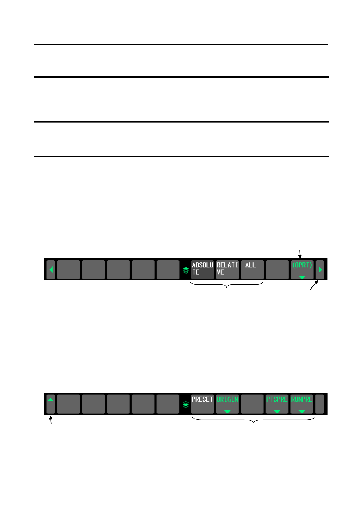
1.1.2 General Screen Operations
- Procedure
1 By pressing a function key on the MDI panel, the chapter selection soft keys that belong to the
function are displayed.
Example 1)
Operation selection key
Chapter selection so ft keys
2 When one of the chapter selection soft keys is pressed, the screen of the chapter is displayed. If the
soft key of a desired chapter is not displayed, press the continuous menu key.
In a chapter, a further choice may be made from multiple chapters.
3 When the screen of a desired chapter is displayed, press the operation selection key to display
operations to be performed.
4 Select a desired operation with the operation selection soft key.
Depending on the operation to be executed, an auxiliary menu of soft keys is displayed. Perform an
operation according to the indications on the auxiliary menu.
Example 2)
Operation selec t ion soft keys Return menu key
Continuous menu ke
- 1 -
Page 24
1. DISPLAY AND OPERATION B-64695EN/01
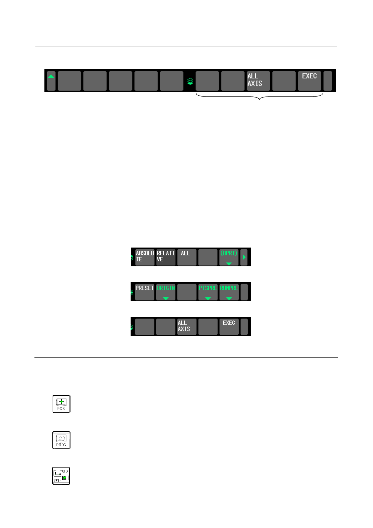
Example 3)
Auxiliary menu
5 To return to the display of chapter selection soft keys, press the return menu key.
A general screen display procedure is provided above. The actual display procedure varies from one
screen to another.
For details, see each description of operation.
- Button design change depending on soft key state
The soft keys assume one of the following states, depending on the selection target:
• Chapter selection soft keys
• Operation selection soft keys
• Auxiliary menu of operation selection soft keys
Depending on the state, the button images of the soft keys change.
From the button images, which state the soft keys are assuming can be known.
Example)
• Chapter selection soft keys
• Operation selection soft keys
• Auxiliary menu of operation selection soft keys
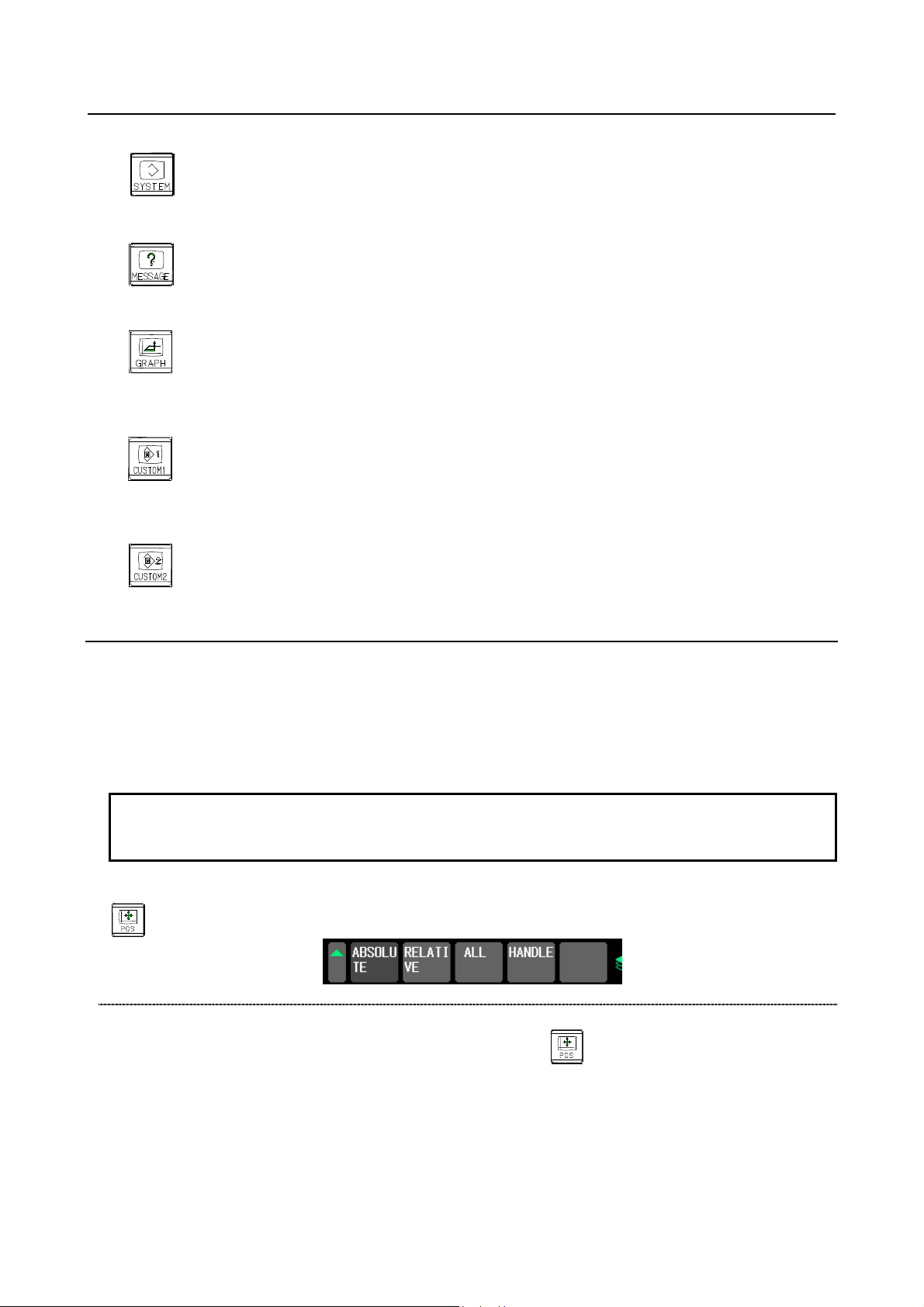
1.1.3 Function Keys
Function keys are provided to select the type of screen to be displayed. The following function keys are
provided on the MDI panel:
Press this key to display the position screen.
Press this key to display the program screen.
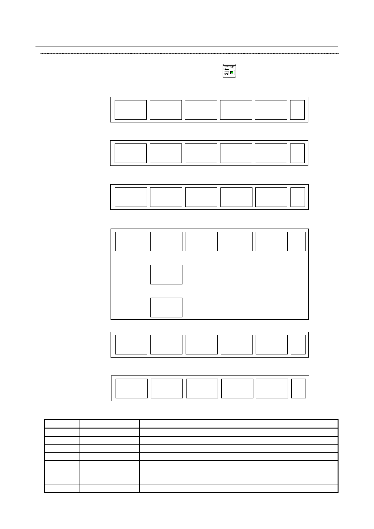
Press this key to display the offset/setting screen.
- 2 -
Page 25
B-64695EN/01 1. DISPLAY AND OPERATION
NOTE
2 Some soft keys are not displayed depending on the option configuration.
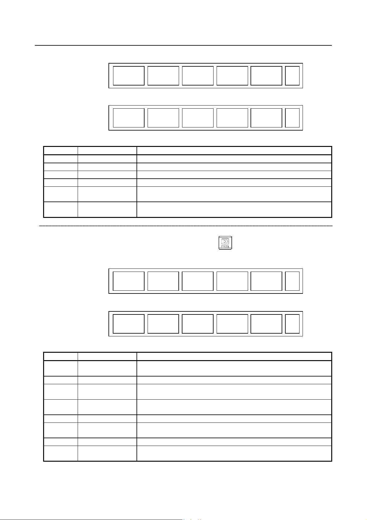
Press this key to display the system screen.
Press this key to display the message screen.
Press this key to display the graphics screen.
Press this key to display the custom screen 1 (conversational macro screen or C Language Executor
screen).
Press this key to display the custom screen 2 (conversational macro screen or C Language Executor
screen).
1.1.4 Soft Keys
By pressing a soft key after a function key , the corresponding screen of the function can be displayed.
The chapter selection soft keys of each function are described below.
The horizontal four keys on the right-hand side are assigned to chapter selection soft keys. When multiple
pages are used for chapter selection soft keys, [+] is displayed on the continuous menu key (rightmost soft
key). Press the continuous menu key to switch between chapter selection soft keys.
1 Press function keys to switch between screens that are used frequently.
If position indications are provided on the left half of the screen when a key other than the function key
is pressed, the left half of the soft keys is displayed as follows at all times:
Position display screen
The chapter selection soft key s that belong to the function key
described below.
and the function of each screen are
- 3 -
Page 26
1. DISPLAY AND OPERATION B-64695EN/01
ABS
REL
ALL
HNDL
(OPRT)
Page 1
+
(1)
(2)
(3)
(4)
(5)
MONI
3-D
MANUAL
(OPRT)
Page 2
+
(6)
(7)
(8)
(9)
(10)
No.
Chapter menu
Description
(1)
ABS
Selects the absolute coordinate display screen.
(2)
REL
Selects the relative coordinate display screen.
(3)
ALL
Selects the overall coordinate display screen.
(4)
HNDL
Selects the operation screen for manual handle operation.
load meter, and speedometer.
MANUAL
PROGRA
M
FOLDER
NEXT
CHECK
(OPRT)
Page 1
+
(1)
(2)
(3)
(4)
(5)
TIME
JOG
RSTR
ROBOT
SELECT
(OPRT)
Page 2
+
(6)
(7)
(8)
(9)
(10)
No.
Chapter menu
Description
currently registered.
(2)
FOLDER
Selects the screen for displaying a list of part programs cur rently registered.
executed and the next block to be executed among the command values.
and so forth simultaneously.
(6)
TIME
Selects the screen for displaying executed program operation time.
program format from the MDI.
(8)
RSTR
Selects the operation screen for restarting an interrupted program operation.
Robot connection function.
Table 1.1.4 (a) Position di splay screen
(6) MONI
(7)
3-D
Selects the screen for displaying the servo axis load meter, serial spindle
Displays a handle pulse interrupt amount in three-dimensional manual feed.
Program screen
The chapter selection soft key s that belong to the function key
described below.
Table 1.1.4 (b) Program
(1) PROGRAM
Selects the screen for displaying and modifying a content of part programs
and the function of each screen are
(3) NEXT
(4) CHECK
(7) JOG
(9) ROBOT SELECT
Selects the screen for displaying the command values of the block currently
Selects the screen for displaying programs, position data, m odal i nformation,
Selects the screen for executing, in the JOG mode, data specified in the
Selects the screen for registering robot programs and part programs for the
- 4 -
Page 27
B-64695EN/01 1. DISPLAY AND OPERATION
OFFSET
SETTING
WORK
(OPRT)
Page 1
+
(1)
(2)
(3)
(4)
(5)
MACRO
OPR
TOOL
MANAGER
(OPRT)
Page 2
+
(6)
(7)
(8)
(9)
(10)
OFST.2
W.SHFT
GEOM.2
(OPRT)
Page 3
+
(11)
(12)
(13)
(14)
(15)
PR-LV
EXTEND
OFFSET
CHOPP
ING
(OPRT)
Page 4
+
CHUCK
TAIL
LANG.
PROTECT
GUARD
(OPRT)
Page 5
+
(16)
(17)
(18)
(19)
(20) (21)
(22)
(23)
(24)
(25)
TOOL
LIFE
(OPRT)
Page 6
+
(26)
(27)
(28)
(29)
(30)
MACHIN
LEVEL
QUALTY
SELECT
or
or
No.
Chapter menu
Description
(1)
OFFSET
Selects the screen for setting tool offset values.
(2)
SETTING
Selects the screen for setting the setting parameters.
(3)
WORK
Selects the screen for setting a workpiece coordinate system offset.
(6)
MACRO
Selects the screen for setting macro variables.
operator's panel as soft switches.
(9)
TOOL MANAGER
Selects the screen for setting data related to t ool management.
(11)
OFST.2
Selects the screen for setting a Y-axis offset.
Offset/setting screen
The chapter selection soft key s that belong to the function key
and the function of each screen are
described below.
(8) OPR
Selects the screen for operating some operation switches on the machine
Table 1.1.4 (c) Offset
- 5 -
Page 28
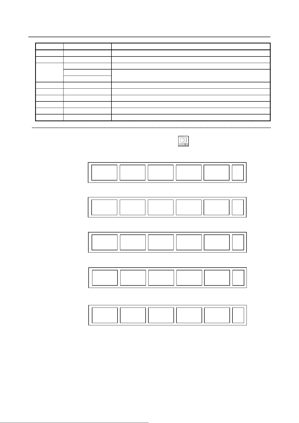
1. DISPLAY AND OPERATION B-64695EN/01
No.
Chapter menu
Description
(12)
W.SHFT
Selects the screen for setting a workpiece coordinate system shift value.
(13)
GEOM.2
Selects the screen for setting a second geometry offset.
PR-LV
Selects the screen for setting a precision level.
MACHIN LEVEL
QUALTY SELECT
(18)
EXTEND OFFSET
Selects the screen for setting the offset s of the fourth and fifth axes.
(21)
CHUCK TAIL
Selects the chuck tail stock barrier screen.
(22)
LANG.
Selects the screen for setting a display language.
(23)
PROTECT
Selects the screen for setting data protection.
(24)
GUARD
Selects the screen for setting wrong operation prevention.
(29)
TOOL LIFE
Selects the screen for operations and setting related to tool life management.
PARAM
DGNOS
SERVO
GUIDEM
SYSTEM
(OPRT)
Page 1
+
(1)
(2)
(3)
(4)
(5)
MEMORY
PITCH
SERVO
PARAM
SP.SET
(OPRT)
Page 2
+
(6)
(7)
(8)
(9)
(10)
PMC
MAINTE
PMC
LADDER
PMC
CONFIG
(OPRT)
Page 3
+
(11)
(12)
(13)
(14)
(15)
MCNG
TUNING
ALL IO
ALL IO
OPEHIS
(OPRT)
Page 4
+
(16)
(17)
(18)
(19)
(20)
COLOR
MAINTE
M
-INFO
W. DGNS
(OPRT)
Page 5
+
(21)
(22)
(23)
(24)
(25)
(17)
Selects the screen for setting a precision level or smoothing level.
System screen
The chapter selection soft key s that belong to the function key
described below.
and the function of each screen are
- 6 -
Page 29

B-64695EN/01 1. DISPLAY AND OPERATION
REMOTE
DIAG
M CODE
(OPRT)
Page 8
+
(36)
(37)
(38)
(39)
(40)
PROFI
SLAVE
DEVNET
MASTER
FL-net
1CH
DEVNET
SLAVE
(OPRT)
Page 9
+
(41)
(42)
(43)
(44)
(45)
DUAL
CHECK
R.TIME
MACRO
(OPRT)
Page 10
+
(46)
(47)
(48)
(49)
(50)
TOUCH
PANEL
FSSB
PRMTUN
P.MATE
MGR.
(OPRT)
Page 6
+
(26)
(27)
(28)
(29)
(30)
EMBED
PORT
PCMCIA
LAN
ETHER
NET
PROFI
MASTER
(OPRT)
Page 7
+
(31)
(32)
(33)
(34)
(35)
ID-INF
(OPRT)
Page 11
+
(51)
(52)
(53)
(54)
(55)
CCLink
REMOTE
ROBOT
STATUS
ROBOT
CON
(OPRT)
Page 12
+
(56)
(57)
(58)
(59)
(60)
USB
(OPRT)
Page 13
+
(61)
(62)
(63)
(64)
(65)
PRFNET
DEVICE
(OPRT)
Page 14
+
(66)
(67)
(68)
(69)
(70)
Ether
Net/IP
PRFNET
CNTRLR
(OPRT)
Page 15
+
(71)
(72)
(73)
(74)
(75)
- 7 -
Page 30

1. DISPLAY AND OPERATION B-64695EN/01
No.
Chapter menu
Description
(1)
PARAM
Selects the screen for setting parameters.
(2)
DGNOS
Selects the screen for displaying CNC state.
(3)
SERVO GUIDEM
Selects the screen for displaying the servo guide mate.
(4)
SYSTEM
Selects the screen for displaying the current system status.
(6)
MEMORY
Selects the screen for displaying the contents of memory.
(7)
PITCH
Selects the screen for setting pith error compensation.
(8)
SERVO PARAM
Selects the screen for setting the servo-r elated parameters.
(9)
SP.SET
Selects the screen for spindle-related setting.
monitoring and tracing, and PMC parameter display/editing.
(12)
PMC LADDER
Selects the screen related to ladder display/editing.
up a sequence program and for setting the PMC function.
(LV1), emphasis on precision (LV10), or smoothing level (LV1 or LV10).
(17)
ALL IO
Selects the screen for data input and output.
(18)
ALL IO
Selects the screen for data input to and output from the memory card.
Selects the screen for displaying the history of operations performed by the
operator and issued alarms.
(21)
COLOR
Selects the screen for setting colors to be used on t he s creen.
(22)
MAINTE
Selects the screen for setting maintenance item s to be managed periodically.
(23)
M-INFO
Selects the screen for displaying information about maintenance performed.
values, torque values, machine signals, and so forth as gr aphs.
(26)
TOUCH PANEL
Selects the screen for setting a touch panel.
bus (FSSB: Fanuc Serial Servo Bus).
(28)
PRMTUN
Selects the screen for setting parameters neces sary for start-up and tuning.
MANAGER
i series I/O Link Option.
(embedded port).
(PCMCIA Ethernet card).
server.
(34)
PROFI MASTER
Selects the screen for making settings related t o the profibus master function.
Diagnosis
(37)
M CODE
Selects the screen for setting an M code group.
(41)
PROFI SLAVE
Selects the screen for making settings related t o the profi-bus slave function.
function.
(43)
FL-net 1CH
Selects the screen fot making settings related to the FL-net (port 1) function.
function.
function.
function.
(51)
ID-INF
Selects the screen for displaying CNC ID information
function.
Table 1.1.4 (d) System
(11) PMC MAINTE
(13) PMC CONFIG
(16) MCNG TUNING
(19) OPEHIS
(24) W.DGNS
(27) FSSB
(29)
(31) EMBED PORT
POWER MATE
Selects the screen related to PMC maintenance such as P M C s i gnal state
Displays the screen for displaying/editing data other than ladders that makes
Displays the screen for setting the parameter set for em phasis on speed
Selects the screen for displaying data such as servo positional deviation
Selects the screen for making settings related t o the high-speed serial servo
Selects the screen for making settings related t o the FANUC Servo amplifier
β
Selects the screen for making settings related t o the embedded Ethernet
(32) PCMCIA LAN
(33) ETHERNET
(36) REMOTE DIAG
(42) DEVNET MASTER
(44) DEVNET SLAVE
(46) DUAL CHECK
(47) R.TIME MACRO
(56) CCLink REMOTE
Selects the screen for making settings related t o the embedded Ethernet
Selects the screen for making settings related to the fast Ethernet/fast data
Selects the screen for making settings related t o the Machine Remote
Selects the screen for making settings related t o the DeviceNet master
Selects the screen for making settings related t o the Devicenet slave
Selects the screen for making settings related t o the dual check safety
Selects the screen for making settings related t o the real-time custom macro
Selects the screen for makings settings related to the CC-Link remote device
- 8 -
Page 31

B-64695EN/01 1. DISPLAY AND OPERATION
No.
Chapter menu
Description
(57)
ROBOT STATUS
Selects the robot status screen for the Robot c onnection function.
function.
(61)
USB
Selects the USB Maintenance screen.
function.
that of the Ethernet function.
Selects the screen for making settings related t o the PROFINET IO
Controller function.
ALARM
MSG
HISTRY
MSGHIS
(OPRT)
Page 1
+
(1)
(2)
(3)
(4)
(5)
EMBED
LOG
PCMCIA
LOG
ETHER
LOG
FL-net
1CH
(OPRT)
Page 2
+
(6)
(7)
(8)
(9)
(10)
USB
LOG
(OPRT)
Page 3
+
(11)
(12)
(13)
(14)
(15)
DNET M
HISTRY
DNET S
HISTRY
PRFNET
DEVICE
(OPRT)
Page 4
+
(16)
(17)
(18)
(19)
(20)
Eth/IP
LOG
(OPRT)
Page 5
+
(21)
(22)
(23)
(24)
(25)
PRFNET
CNTRLR
(OPRT)
Page 6
+
(26)
(27)
(28)
(29)
(30)
No.
Chapter menu
Description
(1)
ALARM
Selects the alarm message screen.
(2)
MSG
Selects the operator message screen.
(58) ROBOT CON
(69) PRFNET DEVICE
(72) EtherNet/IP
(73) PRFNET CNTRLR
Selects the screen for making settings related t o the Robot Connection
Selects the screen for making settings related t o the PROFINET IO Device
Selects the screen for making settings related t o the EtherNet/IP function if
operating the EtherNet/IP function on a Fast Ethernet board different from
Message screen
The chapter selection soft key s that belong to the function key
described below.
and the function of each screen are
Table 1.1.4 (e) Message
- 9 -
Page 32

1. DISPLAY AND OPERATION B-64695EN/01
No.
Chapter menu
Description
(3)
HISTRY
Selects the screen for displaying the details of alarms issued so far.
(4)
MSGHIS
Selects the external operator message screen.
Selects the screen for displaying error messages related to t he embedded
Ethernet (embedded port).
Selects the screen for displaying error messages related to t he embedded
Ethernet (PCMCIA Ethernet card).
Selects the screen for displaying error messages related to t he fast
Ethernet/fast data server.
Selects the screen for displaying error messages related to the FL-net (port
1) function.
(12)
USB LOG
Selects the screen for displaying error messages related to t he USB function.
Selects the screen for displaying communication histories related to the
DeviceNet master function
Selects the screen for displaying communication histories related to the
DeviceNet slave function.
Selects the screen for displaying communication histories related to the
PROFINET IO Device function.
Selects the screen for displaying communication histories related to the
board different from that of the Ethernet function.
Selects the screen for displaying communication histories related to the
PROFINET IO Controller function.
PARAM
GRAPH
(OPRT)
Page 1
+
(1)
(2)
(3)
(4)
(5)
No.
Chapter menu
Description
(1)
PARAM
Selects the screen for setting graphic parameter s.
(2)
GRAPH
Selects the screen for graphically displaying the tool path.
DRAW
PARAM
PATH
EXEC
ANIME
EXEC
TOOL
POS
(OPRT)
Page 1
(1) (2)
(3)
(4) (5)
No.
Chapter menu
Description
(1)
DRAW PARAM
Selects the screen for setting drawing parameters.
(2)
PATH EXEC
Selects the screen for drawing tool paths.
(3)
ANIME EXEC
Selects the screen for drawing animation.
(4)
TOOL POS
Selects the screen for displaying tool positions.
(6) EMBED LOG
(7) PCMCIA LOG
(8) ETHER LOG
(9) FL-net 1CH
(16) DNET M HISTRY
(17) DNET S HISTRY
(18) PRFNET DEVICE
(24) Eth/IP LOG
(26) PRFNET CNTRLR
EtherNet/IP function if operating the Ether Net/IP function on a Fast Ethernet
Graphic screen
The chapter selection soft keys that belong to the function key
described below.
When the graphic display function is enabled:
Table 1.1.4 (f) Graphic
When the dynamic graphic display function is enabled:
and the function of each screen are
Table 1.1.4 (g) Graphic
- 10 -
Page 33

B-64695EN/01 1. DISPLAY AND OPERATION
1.2 SYSTEM CONFIGURATION SCREEN
After the system has started normally, you can find the types of installed printed circuit boards and
software types by displayin g a system configuration screen.
1.2.1 Display Method
1 Press function key
2 Press soft key [SYSTEM].
3 Two types of system configuration screen, th e hardware screen and software screen, are provided,
and you can switch between these screens by using the
When all information cannot be displayed on one page of the screen, you can switch to the next page
by using the
.
page keys.
keys.
1.2.2 Hardware Configuration Scree n
- Screen displ ay
- Displayed information
The following explains the displayed information:
1. NAME
MAIN BOARD
• Displays information on the main board, and cards and modules on the main board.
OPTION BOARD
• Displays information on the board installed in the option slot.
DISPLAY
• Displays information on the display unit.
OTHERS
• Displays information on other components (such as an MDI and a basic unit).
2. SLOT
• Displays the number of the slot in which the option board is inserted.
- 11 -
Page 34

1. DISPLAY AND OPERATION B-64695EN/01
System
Software type
CNC(SYSTEM1)
CNC system software 1
CNC(SYSTEM2)
CNC system software 2
CNC(SYSTEM3)
CNC system software 3
CNC(SYSTEM4)
CNC system software 4
CNC(MSG1)
CNC language indication 1
CNC(MSG2)
CNC language indication 2
CNC(MSG3)
CNC language indication 3
CNC(MSG4)
CNC language indication 4
CNC(MSG5)
CNC language indication 5
BOOT
Boot system
PMC(SYSTEM)
PMC function
PMC(LADDER1)
PMC ladder for path 1
PMC(LADDER2)
PMC ladder for path 2
PMC(LADDER3)
PMC ladder for path 3
PMC(LAD DCS)
Dual check safety PMC ladder
SERVO
Digital servo software (up to ten programs displayed)
SPINDLE-1
Spindle 1
SPINDLE-2
Spindle 2
SPINDLE-3
Spindle 3
SPINDLE-4
Spindle 4
1.2.3 Software Configuration Screen
- Screen displ ay
Fig.1.2.3 (a) Software configuration screen
- Displayed information
The following explains the displayed information:
SYSTEM : Software type
SERIES : Software series
EDITION : Software edition
- Displayed systems and corresponding software types
The following lists the correspondence between displayed systems and software:
Table1.2.3 (a) Software types
- 12 -
Page 35

B-64695EN/01 1. DISPLAY AND OPERATION
System
Software type
GRAPHIC
Graphic function
GRAPHIC1
Graphic function
GRAPHIC2
Graphic function
GRAPH(FONT)
Graphic function (additional Chinese font)
MGI(LIB)
Library for MANUAL GUIDE i
MGI(SYSTEM)
System software for MANUAL GUIDE i
MGI(MACRO M)
Macro software for MANUAL GUIDE i (M system)
MGI(MACRO T)
Macro software for MANUAL GUIDE i (T system)
MGI(USER0)
User data 0 for MANUAL GUIDE i
MGI(USER1)
User data 1 for MANUAL GUIDE i
MGI(USER2)
User data 2 for MANUAL GUIDE i
MGI(USER3)
User data 3 for MANUAL GUIDE i
MGI(USER4)
User data 4 for MANUAL GUIDE i
MGI(USER5)
User data 5 for MANUAL GUIDE i
MGI(USER6)
User data 6 for MANUAL GUIDE i
MGI(USER7)
User data 7 for MANUAL GUIDE i
MGI(USER8)
User data 8 for MANUAL GUIDE i
MGI(USER9)
User data 9 for MANUAL GUIDE i
MACRO EXE1
Macro executor 1
MACRO EXE2
Macro executor 2
MACRO EXE3
Macro executor 3
MACRO EXE4
Macro executor 4
MACRO EXE5
Macro executor 5
MACRO EXE6
Macro executor 6
MACRO EXE7
Macro executor 7
MACRO EXE8
Macro executor 8
MACRO EXE9
Macro executor 9
MACRO EXE10
Macro executor 10
MACRO EXE11
Macro executor 11
MACRO EXE12
Macro executor 12
MACRO EXE13
Macro executor 13
MACRO EXE14
Macro executor 14
MACRO EXE15
Macro executor 15
MACRO EXE16
Macro executor 16
MACRO EXE17
Macro executor 17
MACRO EXE18
Macro executor 18
MACRO EXE19
Macro executor 19
MACRO EXE20
Macro executor 20
CEXELIB
Library for C Language Executor
CEXEAPL
Application for C Language Executor
CEXEDATA0
C Language Executor data file 0
CEXEDATA1
C Language Executor data file 1
CEXEDATA2
C Language Executor data file 2
CEXEDATA3
C Language Executor data file 3
CEXEDATA4
C Language Executor data file 4
CEXEDATA5
C Language Executor data file 5
CEXEDATA6
C Language Executor data file 6
CEXEDATA7
C Language Executor data file 7
CEXEDATA8
C Language Executor data file 8
CEXEDATA9
C Language Executor data file 9
EMBED ETHER
Embedded Ethernet software
ETHER DISPLAY
Ethernet Display software
USB SOFT
USB software
PROFI SOFT
PROFIBUS software
- 13 -
Page 36

1. DISPLAY AND OPERATION B-64695EN/01
System
Software type
PROFI MASTER
PROFIBUS Master software
PROFI SLAVE
PROFIBUS Slave software
DEVNT SOFT
DeviceNet software
CC-LINK SOFT
CC-Link software
ETHERNET
Fast Ethernet software
PROFINET
PROFINET software
NETWORK SAFE
Network Safety software
MG0I(LIB)
Library for MANUAL GUIDE 0i
MG0I(SYSTEM)
System software for MANUAL GUIDE 0i
MG0I(EMCR M)
Execution macro software for MANUAL GUIDE 0i (M system)
MG0I(CMCR M)
Conversation macro software for MANUAL GUIDE 0i (M system)
MG0I(EMCR T)
Execution macro software for MANUAL GUIDE 0i (T system)
MG0I(CMCR T)
Conversation macro software for MANUAL GUIDE 0i (T system)
SUG(LIB)
Library for Set-up guidance function
SUG(SYSTEM)
System software for Set-up guidance function
SUG(MACRO M)
Macro software for Set-up guidance function (M system)
• Display of digital servo software
When multiple programs are loaded, up to ten types are displayed.
For the type of servo software used for each axis, check parameter No. 1024.
• Display o f spindle software
The series and edition of software are display ed for each spindle. This inf ormation is displayed for
up to sixteen spindles
• Display of macro executor
The series and edition are displayed for each number specified at the time of P-CODE macro
creation.
Up to 20 types of macro executor are displ ayed.
1.2.4 Outputting System Configuration Data
Data displayed on the system configuration screen can be output to an input/output device.
(1) Press function key
(2) Press the EDIT switch on the machine operator's panel.
(3) Press soft key [SYSTEM] to display the system configuration screen.
(4) Press soft key [(OPRT)] and select soft key [F OUTPUT].
(5) Press soft key [EXCE].
(6) Data is output to the output device selected by parameter No. 20.
Data is output to a file named SYS_CONF.TXT.
.
- 14 -
Page 37

B-64695EN/01 1. DISPLAY AND OPERATION
Diagnosis
0
CNC internal state 1
Diagnosis
2
Dwell execution state
Diagnosis
8
CNC internal state 2
Diagnosis
10
RS-232C interface output state
Diagnosis
30
TH alarm character count (foreground edit)
Diagnosis
31
TH alarm character code (foreground edit)
Diagnosis
32
TH alarm character count (background edit)
1.3 DIAGNOSIS FUNCTION
1.3.1 Displaying Diagnosis Screen
(1) Press function key
.
(2) Press soft key [DGNOS], then a diagnosis screen is disp layed.
1.3.2 Contents Displayed
Causes when the machine does not travel in spite of giving a command
[Data type] Bit
NAME Internal state when "1" is displayed
INPOSITION CHECK In-position check is being done.
FEEDRATE OVERRIDE 0% Feedrate override is 0%.
JOG FEED OVERRIDE 0% Jog feedrate override is 0%.
INTER/START LOCK ON Interlock/start lock is on.
SPEED ARRIVAL ON The system is waiting for the speed arrival signal to turn
on.
WAIT REVOLUTION The system is waiting for the spindle one-rotation signal
in threading.
STOP POSITION OCDER The system is waiting for the rotation of the position
coder in spindle feed per revolution.
When a dwell is being executed, "1" is displayed.
[Data type] Bit
NAME Internal state when "1" is displayed
FOREGROUND READING Data is being input in the foreground.
BACKGROUND READING Data is being input in the background.
RS-232C interface output state
When data is being output through the RS-232C interface, "1" is indicated.
State of TH alarm
[Data type] 2-word axis
The position where the TH alarm occurred in foreground input is indicated by the number
of characters from the beginning of the block.
[Data type] 2-word axis
The character code of the character at which the TH alarm occurred in for egro un d i np ut is
indicated.
[Data type] 2-word axis
The position where the TH alarm occurred in background input is indicated by the
number of characters from the beginning of the block.
- 15 -
Page 38

1. DISPLAY AND OPERATION B-64695EN/01
Diagnosis
33
TH alarm character code (background edit)
Diagnosis
43
Number of the current display language of the CNC screen
#7
#6
#5
#4
#3
#2
#1
#0
Diagnosis
200
OVL
LV
OVC
HCA
HVA
DCA
FBA
OFA
#7
#6
#5
#4
#3
#2
#1
#0
Diagnosis
201
ALD
PCR EXP
[Data type] 2-word axis
The character code of the character at which the TH alarm occurred in backgrou nd input
is indicated.
Display language of the CNC screen
[Data type] Byte
The number of the current display language of the CNC screen is indicated.
The correspondence between languages and numbers is show below.
0 : English
1 : Japanese
2 : German
3 : French
4 : Chinese (traditional characters)
5 : Italian
6 : Korean
7 : Spanish
8 : Dutch
9 : Danish
10 : Portuguese
11 : Polish
12 : Hungarian
13 : Swedish
14 : Czech
15 : Chinese (simplified characters)
16 : Russian
17 : Turkish
18 : Bulgarian
19 : Rumanian
20 : Slovak
21 : Finnish
22 : Hindi
23 : Vietnamese
24 : Indonesian
25 : Slovenian
Details of serial Pulsecoder
#0 OFA Overflow alarm
#1 FBA Disconnection alarm
#2 DCA Discharge alarm
#3 HVA Overvoltage alarm
#4 HCA Abnormal current alarm
#5 OVC Over current alarm
#6 LV Insufficient voltage alar m
#7 OVL Overload alarm
#4 EXP
#7 ALD
- 16 -
Page 39

B-64695EN/01 1. DISPLAY AND OPERATION
ALD
EXP
Description
0
-
Amplifier overheat
1
-
Motor overheat
1
0
Built-in Pulsecoder (hard)
1
1
Disconnection of separated type Pulsecoder (hard)
0
0
Disconnection of Pulsecoder (software)
NOTE
position return mode is started.
#7
#6
#5
#4
#3
#2
#1
#0
Diagnosis
202
CSA
BLA
PHA
RCA
BZA
CKA
SPH
#7
#6
#5
#4
#3
#2
#1
#0
Diagnosis
203
DTE
CRC
STB
PRM
#7
#6
#5
#4
#3
#2
#1
#0
Diagnosis
204
OFS
MCC
LDA
PMS
#7
#6
#5
#4
#3
#2
#1
#0
Diagnosis
205
OHA
LDA
BLA
PHA
CMA
BZA
PMA
SPH
Overload alarm
Disconnection alarm
#6 PCR The one-rotation signal of the position detector was caught before a manual reference
position return is performed. Since the manual reference position return grid was
established, a manual reference position return is enabled.
This bit is valid only when the operation of the manual reference
#0 SPH Serial Pulsecoder or feedback cable is faulty.
Counting of feedback cable is erroneous.
#1 CKA Serial Pulsecoder is faulty.
Internal block stopped.
#2 BZA Battery voltage became 0.
Replace the battery and set the reference posi tion.
#3 RCA Serial Pulsecoder is faulty.
The speed was incorrectly counted.
#4 PHA Serial Pulsecoder or feedback cable is erroneous.
Counting of feedback cable is erroneous.
#5 BLA Battery voltage is low (warning)
#6 CSA Hardware of serial Pulsecoder is abnormal
#4 PRM A parameter failure was detected on the digital servo sid e. See the cause and
measure described in diagnosis No. 352.
#5 STB Communication failure of serial Pulsecoder.
Transferred data is erroneous.
#6 CRC Communicatio n failure of serial Pulsecoder.
Transferred data is erroneous.
#7 DTE Communication failure of serial Pulsecoder.
There is no response for communication.
#3 PMS Feedback is not correct due to faulty serial Pulsecoder C o r feedback cable.
#4 LDA Serial Pulseco der LED is abnormal
#5 MCC Contacts of MCC of ser vo amplifier is melted.
#6 OFS Abnormal current value result of A/D conversion of digital servo
Details of separate serial Pulsecoder alarm s
#0 SPH A soft phase data error occurred in the separate P ulsecoder.
#1 PMA A pulse error occurred in the separate Pulsecoder.
#2 BZA The battery voltage for the separate Pu lsecoder is zero.
- 17 -
Page 40

1. DISPLAY AND OPERATION B-64695EN/01
#7
#6
#5
#4
#3
#2
#1
#0
Diagnosis
206
DTE
CRC
STB
#7
#6
#5
#4
#3
#2
#1
#0
Diagnosis
202
SEM
#7
#6
#5
#4
#3
#2
#1
#0
Diagnosis
206 ROT
LIN
SEM
ROT
LIN
Separate position detector (serial) (linear scale)
0 0 1
Separate position detector (serial) (rotary scale)
0 1 0
Separate position detector (AB phase)
0 0 0
Semi-closed mode
1 0 0
#7
#6
#5
#4
#3
#2
#1
#0
Diagnosis
280
DIR
PLS
PLC MOT
Diagnosis
300
Position error of an axis in detection unit
Position error =
Feed rate [mm/min] × 100
×
1
60 × servo loop gain [1/sec]
Detection unit
Diagnosis
301
Distance from reference position of an axis in detection unit
#3 CMA A count error occurred in the separate Pulsecoder.
#4 PHA A phase data error occurred in the separate linear scale.
#5 BLA A low battery voltage occurred in the separate Pulsecoder.
#6 LDA An LED error o ccurred in the separate Pulsecoder.
#7 OHA Overheat occurred in the separate Pulsecoder.
#5 STB A stop bit error occurred in the separate Pulsecoder .
#6 CRC A CRC error occurred in the separate Pulsecoder.
#7 DTE A data error o ccurred in the separate Pulsecoder.
Connection system of scale
#7 SEM Separate position detector is not used (semi-closed loop)
#0 LIN Separate position detector is serial interface linear scale
#1 ROT Separate position detector is serial interface rotary scale
Details of invalid servo parameter alarms (on the CNC side)
When servo alarm No. 417 is issued, and diagnosis No. 203#4 = 0, its cause is indicated.
When diagnosis No. 203#4 = 1, see diagnosis No. 352.
#0 MOT The motor type specified in parameter No. 2020 falls outside the predetermined range.
#2 PLC The number of velocity feedback pulses per motor revolution, specif ied in parameter No.
2023, is zero or less. The value is invalid.
#3 PLS The number of position feedback pulses per motor revolution, specified in parameter No.
2024, is zero or less. The value is invalid.
#4 DIR The wrong direction of rotation for the motor is specified in parameter No. 2022 (the
value is other than 111 or -111).
Position error amount
Machine position
- 18 -
Page 41

B-64695EN/01 1. DISPLAY AND OPERATION
Diagnosis
302 Distance from the end of the deceleration dog to the first grid point
NOTE
first grid point is assumed.
Diagnosis
304
Reference counter amount in each axis
Diagnosis
308
Servo motor temperature (°C)
Diagnosis
309
Pulsecoder temperature (°C)
NOTE
of up to 5°C.
Distance from the end of the deceleration dog to the first grid point
[Data type] Real axis
[Unit of data] Machine unit
[Valid data range] 0 to ±99999999
For the reference position setting without a dog, the distance from
the beginning of the reference position setting without a dog to the
Reference counter
[Data type] 2-word axis
[Unit of data] Detection unit
[Valid data range] –99999999 to 99999999
Motor temperature information
[Data type] Byte axis
[Unit of data] °C
[Valid data range] 0 to 255
The temperature of the coil of the servo motor is indi cated. Wh en the t emperature reaches
140°C, a motor overheat alarm is issued.
[Data type] Byte axis
[Unit of data] °C
[Valid data range] 0 to 255
The temperature of the printed circuit board in the Pulsecoder is indicated. When the
temperature reaches 100°C (approximately 85°C for the temperature of atmosphere in the
Pulsecoder), a motor overheat alarm is issued.
1 Temperature information has the following error:
50°C to 160°C ±5°C
•
160°C to 180°C ±10°C
•
2 The temperature at which an overheat alarm is issued has an error
Cause that sets bit 4 (APZ) of parameter No. 1815 to 0
You can find the cause that sets bit 4 (APZ) of parameter No. 1815 to 0 by checking diagnosis Nos. 310
and 311.
Once diagnosis No. 310 or 311 is set to 1, this setting is kept unchanged until the zero point of the
absolute position detector of the cor responding axis is set again. Po ssible causes that set APZ to 0 are as
follows:
- 19 -
Page 42

1. DISPLAY AND OPERATION B-64695EN/01
#7
#6
#5
#4
#3
#2
#1
#0
Diagnosis
310
DTH
ALP BZ2
BZ1
PR2
PR1
#7
#6
#5
#4
#3
#2
#1
#0
Diagnosis
311
DUA
XBZ
GSG
AL4
AL3
AL2
AL1
Diagnosis
352
Detail number for invalid servo parameter setting alarm
number
13100.
Bit 2 of parameter No. 2300=0
#0 PR1 One of the following parameters was changed:
No.1815#0, No.1815#1, No.1815#6, No.1817#3, No.1820, No.1821, No.1822, No.1823,
No.1850, No.1868, No.1869, No.1874, No.1875, No.1876, No.1883, No.1884, No.2022,
No.2084, No.2085, No.2179, increment system for a rotary axis A type, No.11802#6,
No.11810
#1 PR2 Bit 1 (ATS) of parameter No. 8303 was changed. Alternatively, when bit 7 (SMA) of
parameter No. 8302 was set to 1, APZ of the axis to b e synchronized together was set t o
0.
#2 BZ1 A battery voltage of 0 V was detected. (I nductosyn)
#3 BZ2 A battery voltage of 0 V was detected. (Separate position detector)
#5 ALP The zero point was set by MDI when the α pulse coder had not rotate one or more turns.
Alternatively, the CNC could not obtain a correct value from the absolute pulse coder.
#6 DTH An axis detach operation was performed by the controlled-axis detach signal DTCH
<G124> or by setting bit 7 (RMV) of parameter No. 0012.
#0 AL1 An SV alarm (SV301 to SV305) was issued.
#1 AL2 When bit 1 (CRF) of parameter No. 1819 was set to 1, alarm SV0445, “SOFT
DISCONNECT ALARM”, SV0447, “HARD DISCONNECT(EXT)”, or SV0646,
“ABNORMAL ANALOG SIGNAL(EXT)”, was detected.
#2 AL3 A battery voltage of 0 V was detected. (Built-in serial Pul secoder)
#3 AL4 Alarm SV0367, “COUNT MISS(INT)”, was detected.
#4 GSG The status of broken-wire alarm ignore signal NDCAL (G202) changed from 1 to 0.
#5 XBZ A battery voltage of 0 V or alarm SV0382, “COUNT MISS(EXT)”, was detected.
(Separate serial position detector)
#6 DUA When bit 1 (CRF) of parameter No. 1819 was set to 1, alarm SV0421, “EXCESS
ERROR(SEMI-FULL)”, was detected.
Details of invalid servo parameter setting alarms (on the servo side)
Indicates information that can be used to id entify the l ocatio n (parameter) an d cause of an
invalid servo parameter setting alarm (servo alarm No. 417) .
This diagnosis information is valid when the following conditions are satisfied.
• Servo alarm No. 417 has occurred.
• Bit 4 of diagnosis No. 203 (PRM) = 1
See the following table for the displayed detail numbers and the corresponding causes.
For further detail information that could be used to take measures, refer to FANUC AC
Servo Motor αis/αi/βis series Parameter Manual (B-65270EN).
- Detailed descriptions about invalid servo parameter setting alarms
Detail
0233 2023
0234 2023
Parameter No. Cause Action
When initialization bit 0 is set to 1, the
number of velocity pulses exceeds
When a DD motor is used, a value
smaller than 512 is set as the number of
velocity pulses.
Correct the number of velocity pulses so
that it is within 13100.
Set 512 or a greater number as the
number of velocity pulses, or disable the
DD motor.
- 20 -
Page 43

B-64695EN/01 1. DISPLAY AND OPERATION
number
2185).
0435
integral gain overflowed.
integral gain parameter.
parameter setting.
0475
parameter (POA1) overflowed.
(−1) × (desired value)/10.
The internal value of a parameter
overflowed.
Decrease the setting to the extent that
is not caused.
overflowed.
is not caused.
0699
0755
overflowed.
Set 0.
0765
overflowed.
Set 0.
detector).
feed gear denominator.
gear denominator.
exceed 100.
effect.
setting so that no overflow will occur.
is in use).
Detail
0243 2024
0434
0443
0444
0445
0474
0534
0535
0544
0545
0694
0695
0696
Parameter No. Cause Action
2043
2044
2047
2053
2054
2069
When initialization bit 0 is set to 1, the
number of position pulses exceeds
13100.
The internal value of the velocity loop
The internal value of the velocity loop
proportional gain overflowed.
The internal value of the observer
related to dead zone compensation
The internal value of a parameter
related to dead zone compensation
The internal value of the velocity
feed-forward coefficient overflowed.
Correct the number of position pulses so
that it is within 13100.
Use the position feedback pulse
conversion coefficient (parameter No.
Decrease the value of the velocity loop
Use the function for changing the
internal format of the velocity loop
proportional gain (bit 6 of parameter No.
2200). Alternatively, decrease the
Correct the setting to
the illegal servo parameter setting alarm
Decrease the setting to the extent that
the illegal servo parameter setting alarm
Decrease the velocity feed-forward
coefficient.
0754
0764
0843 2084
0853 2085
0883 2088
0884
0885
0886
0994
0995
0996
2075
2076
2088
2099
The setting for this parameter has
The setting for this parameter has
A positive value is not set as the flexible
feed gear numerator.
Alternatively, the following condition
exists: Feed gear numerator >
denominator × 16
A positive value is not set as the flexible
For an axis with a serial type separate
detector, a value exceeding 100 is set
as the machine velocity feedback
coefficient.
The internal value of the machine
velocity feedback coefficient overflowed.
The internal value for N pulse
suppression overflowed.
This parameter is not used at present.
This parameter is not used at present.
Set a positive value as the flexible feed
gear numerator.
Alternatively, satisfy the following
condition: Feed gear numerator ≤
denominator × 16
(except for phase A-/B-specific separate
Set a positive value as the flexible feed
For an axis with a serial type separate
detector, the upper limit of the machine
velocity feedback coefficient is 100.
Correct the coefficient so that it does not
Decrease the machine velocity feedback
coefficient.
Alternatively, use the vibration-damping
control function that has an equivalent
Disable the N pulse suppression
function.
Alternatively, decrease the parameter
1033 2103
The retract distance related to an
abnormal load differs between the L and
M axes (if the same-axis retract function
- 21 -
Set the same value for both the L and M
axes.
Page 44

1. DISPLAY AND OPERATION B-64695EN/01
number
not input.
2079
overflows.
overflows.
Enlarge the AMR offset setting range
value within a range of ±60.
1459
below 6.
1503
2150
A value equal to or greater than 10 is set.
Set a value less than 10.
set to 1, and No. 2178=0 is set.
to 0.
the setting of parameter No. 1821 is set.
of parameter No. 1821.
the setting of parameter No. 2023 is set.
of parameter No. 2023.
(1024 poles).)
issued.
Detail
1123 2112
1182
1284
1285
1294
1295
1393 2139
1454
1455
1456
1493 2149
Parameter No. Cause Action
2118
2078
2128
2129
2145
Although a linear motor is used, the
AMR conversion coefficient parameter is
The dual position feedback conversion
coefficient has not been specified.
When a small value is set as the number
of velocity pulses, the internal value of a
parameter related to current control
When a large value is set as the number
of velocity pulses, the internal value of a
parameter related to current control
The AMR offset setting value of a linear
motor exceeds ±45.
Velocity feed-forward coefficient for
cutting overflowed.
A value greater than 6 is specified in this
parameter.
Set the AMR conversion coefficient.
Specify the dual position feedback
conversion coefficient.
Decrease the value in this parameter to
the extent that the alarm is not caused.
When the value set in this parameter is
resolved to the form a × 256 + b, set a
smaller value in a again.
(bit 0 of parameter N. 2270=1) to input a
Decrease the velocity feed-forward
coefficient.
Only 6 or less can be specified in this
parameter. Change the setting to 6 or
1786 2178
1793 2179
1853 2185
2203 2220#0
2243 2224#5
Bit 6 of No. 2212 or bit 6 of No. 2213 is
A negative value or a value greater than
A negative value or a value greater than
If pole detection is enabled (bit 7 of No.
2213=1) and a non-binary detector is
enabled (bit 0 of No. 2220=1), an illegal
servo parameter setting alarm is issued
when any of the following is set:
- AMR conversion coefficient 1 ≤ 0
- AMR conversion coefficient 2 ≤ 0
- AMR conversion coefficient 2 > 512
(The settable range is 1 (2 poles) to 512
This alarm is issued when a setting is
made to neglect the invalid setting of the
parameter for the feed-forward timing
adjustment function (bit 5 of No. 2224=1)
and a command for nano interpolation is
Set bit 6 of No. 2212 or bit 6 of No. 2213
Set a positive value less than the setting
Set a positive value less than the setting
Set the AMR conversion coefficients
correctly.
Use either one.
- 22 -
Page 45

B-64695EN/01 1. DISPLAY AND OPERATION
number
disabled.
software.
check interface unit) to the first SDU unit.
unit.
unit (bit 1 of No. 2278=1).
Any of the following settings is made:
unit (bit 1 of No. 2278=1).
first/second SDU unit).
unit).
SDU unit).
Detail
2632 2263
2780
2781
2782
Parameter No. Cause Action
2277#5,6,7
2278#0,2,4
24096
2277#5,6,7
2278#1,3,4
24097
2277#5,6,7
2278#0,4
24096
When the lifting function against gravity
is enabled (bit 7 of No. 2298=1) or the
post-servo-off travel distance monitor
function is enabled (bit 5 of No. 2278=1),
the function for enabling the CNC
software to post the detection unit to the
servo software is not supported and the
setting of the detection unit (No. 2263) is
When the first SDU unit is not used
(No.24096=0), a setting is made to
connect a detector (acceleration sensor,
temperature detection circuit, or analog
When the second SDU unit is not used
(No.24097=0), a setting is made to
connect a detector (acceleration sensor,
temperature detection circuit, or analog
check interface unit) to the second SDU
Any of the following settings is made:
• For use with the first SDU unit, both
of an acceleration sensor and
temperature detection circuit are
enabled.
• Settings are made to use the first
SDU unit (No.24096>0), disable an
acceleration sensor (bits 5, 6, 7 of
No. 2277=0,0,0), and read
acceleration data from the second
Take one of the following actions:
1) Set a value in par ameter No. 2263.
2) Disable the lifting function against
gravity and the post-servo-off travel
distance monitor function.
3) Use CNC software that supports the
function for enabling the detection
unit to be posted to the servo
Check the FSSB setting (No.24096) or
the detector setting (bits 0, 2, and 4 of
No. 2278).
Check the FSSB setting (No.24097) or
the detector setting (bits 1, 3, and 4 of
No. 2278).
Check the settings of the acceleration
sensor and temperature detection circuit.
2277#5,6,7
2783
2784
2785
2786
2278#1,4
24097
1815#1
2277#5,6,7
2278#0,1,4
1815#1
2277#5,6,7
2278#0,4
1815#1
2277#5,6,7
2278#1,4
• For use with the second SDU unit,
both of an acceleration sensor and
temperature detection circuit are
enabled.
• Settings are made to use the second
SDU unit (No.24097>0), disable an
acceleration sensor (bits 5, 6, 7 of
No. 2277=0,0,0), and read
acceleration data from the second
At the time of full-closed system setting,
a detector other than a separate position
detector is connected (with the
At the time of full-closed system setting,
a detector other than a separate position
detector is connected (with the first SDU
At the time of full-closed system setting,
a detector other than a separate position
detector is connected (with the second
- 23 -
Check the settings of the acceleration
sensor and temperature detection circuit.
Modify the setting of the detector.
Modify the setting of the detector.
Modify the setting of the detector.
Page 46

1. DISPLAY AND OPERATION B-64695EN/01
number
second SDU units.
24097
i
No. 2300=0).
extension function.
3603
value to 0.
3663
4553
2455
A negative value is set.
Set the value 0 or a greater number.
4563
2456
A value not within 0 to 12 is set.
Set a value within 0 to 12.
reference counter capacity parameter.
8256
24097
No.2200=1)
Detail
2787 2278#0,#1
2788
3002 2300#3,#7
3012 2301#2,#7
Parameter No. Cause Action
1815#1
2277#5,6,7
2278#4
2278#0,1
24096
A setting is made to connect two
temperature detection circuits.
A setting is made to connect two
temperature detection circuits.
The αiCZ detection circuit and linear
motor position detection circuit do not
support overheat signal connection.
• When bit 2 of No. 2301=1
Hardware (PS, SV) that does not
support DC link voltage information
output is connected, but bit 2 of No.
2301 is set to 1.
• When bit 7 of No. 2301=1
The CNC software does not support
the torque control setting range
Only one temperature detection circuit
can be connected. Modify the setting so
that data is read from one of the first and
Only one temperature detection circuit
can be connected. Modify the setting so
that data is read from one of the first and
second SDU units.
Replace the α
linear motor position detection circuit with
those circuits that support overheat
signal connection. Alternatively, modify
the setting so that the overheat signal is
read from a DI signal (bit 3 of parameter
• When bit 2 of No. 2301=1
Set bit 2 of No. 2301 to 0.
• When bit 7 of No. 2301=1
Use CNC software that supports the
function.
CZ detection circuit and
3553
3603
3603
8213 1821
8254
8255
9053
10010
10016
10019
2355 The value 4 or a smaller number is set. Set the value 5 or a greater number.
2113
2360
2363
2366
2366 The value 4 or a smaller number is set. Set the value 5 or a greater number.
1825
1815#1
24096
2200#0
The value 95 or smaller number is set.
A positive value is not set in the
A position gain of 0 is set, or the internal
position gain value has overflowed.
At the time of full-closed system setting,
no separate detector interface unit is set.
The internal value of a parameter related
to feedback mismatch detection
has overflowed.
Set the value 96 or a greater number.
Alternatively, if no resonance elimination
filter is used, set all of the center
frequency, band width, and dumping
Set a positive value in this parameter.
Set a value other than 0
(when setting = 0).
Set a separate detector interface unit.
Check whether correct values are set for
the flexible feed gear, number of position
pulses, and number of velocity pulses
and the counting direction of separate
detector data is correct. When there is no
problem with them, disable "feedback
mismatch detection". (bit 0 of
- 24 -
Page 47

B-64695EN/01 1. DISPLAY AND OPERATION
number
cycle.
reverse connection bit is set.
reverse connection bit cannot be used.
that supports the function.
2014#0
2004
2013#0
The Series 0i-F does not allow HRV1
setting. Set HRV2, HRV3.
setting.
HRV3.
pair does not support HRV3.
control types.
setting.
parameter setting.
Diagnosis
355
Communication alarm ignore counter (separate type)
Diagnosis
356
Link processing counter (built-in type)
Diagnosis
357
Link processing counter (separate type)
Diagnosis
358
V ready-off information
Detail
10033 2004
10053 2018#0
10062 2209#4
10092
10093
10103
10113 2013#0
10123 2013#0
Parameter No. Cause Action
2004
2013#0
Illegal control cycle setting
This error occurs if automatic
modification is carried out for the control
When a linear motor is used, the scale
The amplifier used does not support the
HC alarm prevention function.
Different control cycles are set within one
servo CPU.
HRV1 is set.
Current cycle mismatch alarm.
This alarm is issued if the specified
current cycle does not match the actual
Alarm for indicating the disability of
HRV3 setting.
This alarm is issued when the axis
supports HRV3 but the other axis of the
Correct this parameter related to
interrupt cycle setting.
When the linear motor is used, the scale
When you use the current amplifier
continuously, set the function bit shown
to the left to 0.
When using the HC alarm prevention
function, use an appropriate amplifier
Set the same control cycle for axes
controlled by one servo CPU.
An axis for which HRV3 is specified
exists on the same optical cable. Review
the placement of the amplifier, or disable
Eliminate the cause of the disability in
setting the other axis. Alternatively,
cancel the HRV3 setting.
10133
10202
10212
2013#0
2014#0
2277#5,6,7
2278#0,2,4
2277#5,6,7
2278#1,3,4
This alarm is issued when HRV3 is set,
but the amplifier does not support these
The ID of the detector connected to the
first SDU unit differs from the parameter
The ID of the detector connected to the
second SDU unit differs from the
HRV3 is unusable for the axis on which
the alarm was issued.
Check the detector-related parameter or
the state of detector connection.
Check the detector-related parameter or
the state of detector connection.
The number of times a communication error occurred during serial communication with
the detector is indicated.
Data transmitted during communication is guaranteed unless another alarm occurs.
However, if the counter value indicated in this diagnosis information increases in a short
period, there is a high probability that serial communication is disturbed by noise. So,
take sufficient measures to prevent noise.
* For details, refer to a relevant manual on FANUC SERVO MOTOR αi series.
This information is provided to analyze the cause of th e V ready-off alarm (servo alarm
SV0401).
- 25 -
Page 48

1. DISPLAY AND OPERATION B-64695EN/01
SRDY DRDY INTL
CRDY
#15
#14 #13
#12
#11
#10
#09 #08
*ESP
#07
#06 #05
#04 #03
#02 #01
#00
Diagnosis
359
Communication alarm neglect counter (built-in type)
Diagnosis
360
Cumulative value of specified pulses (NC)
Diagnosis
361
Compensation pulses (NC)
Diagnosis
362
Cumulative value of specified pulses (SV)
Diagnosis
363
Cumulative feedback (SV)
Convert the indicated value to a binary representation, and check bits 5 to 14 of the
binary representation.
When amplifier excitation is turned on, these bits are set to 1 sequ entiall y fr om the lowest
bit, which is bit 5. If the amplifier is activated normally, bits 5 to 14 are all set to 1.
Therefore, check the bits sequentially from the lowest bit to find the first bit that is set to
0. This bit indicates that the corresponding processing could not be completed and so the
V ready-off alarm was caused.
# 06 *ESP Converter emergency st op state released
# 10 CRDY Conver ter ready
# 12 INTL DB relay released
# 13 DRDY Amplifier ready (amplifier)
# 14 SRDY Amplifier ready (software)
* For details, refer to a relevant manual on FANUC SERVO MOTOR αi series.
The diagnosis information is the same as that of diagnosis No. 355.
See the descriptions in diagnoses No.355 to 357.
[Data type] 2-word
[Unit of data] Detection unit
[Valid data range] -99999999 to 99999999
Cumulative value of move commands distributed from the CNC since power-on is
indicated.
[Data type] 2-word
[Unit of data] Detection unit
[Valid data range] -99999999 to 99999999
Cumulative value of compensation pulses (backlash compensation, pitch error
compensation, and so on) distributed from the CNC since power-on is indicated.
[Data type] 2-word
[Unit of data] Detection unit
[Valid data range] -99999999 to 99999999
Cumulative value of move pulses and compensation p ulses received by the servo sy stem
since power-on is indicated.
[Data type] 2-word
[Unit of data] Detection unit
[Valid data range] -99999999 to 99999999
Cumulative value of positional feedback p ulses the servo system received from the pulse
coder since power-on is indicated.
- 26 -
Page 49

B-64695EN/01 1. DISPLAY AND OPERATION
Diagnosis
380 Difference between the absolute position of the motor and offset data
M (absolute position of the motor)-S (offset data)
λ (pitch interval)
Diagnosis
381
Offset data from the Inductosyn
Diagnosis
403
Temperature of spindle motor
NOTE
•
For 160 to 180°C 10°C maximum
Diagnosis
410
Spindle load meter indication [%]
Diagnosis
411
Spindle motor speed indication [min-1]
Diagnosis
417
Spindle position coder feedback information
Diagnosis
418
Positional deviation of spindle in position loop mode
Diagnosis
425
Spindle synchronization error
Diagnosis data related to the Inductosyn absolute position detector
[Data type] 2-word axis
[Unit of data] Detection unit
The remainder resulting from the division is displayed.
[Data type] 2-word axis
[Unit of data] Detection unit
Off set data is displayed when CNC calculates the machin e position.
Diagnosis data related to the serial spindles
[Data type] Byte spindle
[Unit of data] °C
[Valid data range] 0 to 255
The temperature of the winding of the spindle motor is indicated.
This information can be used to determine the overheat alarm of the spindle.
(The temperature that causes an overheat alarm varies from motor to motor.)
1 Temperature information has the following error:
50°C to 160°C ±5°C
•
160°C to 180°C ±10°C
•
2 The indicated temperature and the temperature causing an
overheat alarm have the following error:
For lower than 160°C 5°C maximum
•
[Data type] Word spindle
[Unit of data] %
[Data type] Word spindle
[Unit of data] min
[Data type] 2-word spindle
[Unit of data] Detection unit
[Data type] 2-word spindle
[Unit of data] Detection unit
-1
[Data type] 2-word spindle
[Unit of data] Detection unit
When the spindles are in synchronization mode, the absolute value of the synchronization
error when each spindle is set as the slave axis is indicated.
- 27 -
Page 50

1. DISPLAY AND OPERATION B-64695EN/01
Diagnosis 445 Spindle position data
[Data type] 2-word spindle
[Unit of data] Pulse
[Valid data range] 0 to 4095
For the serial spindle, position coder signal pulse data from the one-rotation signal is
indicated as the position data of the spindle.
This data is valid when bit 1 of parameter No. 3117 is set to 1.
To display spindle position data, spindle orientation must be performed once.
Diagnosis 449 Spindle position data (angle)
[Data type] Real spindle
[Unit of data] Refer to table below
[Valid data range] 0 to 359.999[deg]
Diagnosis data No.449 indicates spindle angle from the one-rotation signal when bit 1
(SPP) of parameter No.3117 is set to 1. Spindle angle displays to three decimal places. It
is available for serial spindle. To display spindle angle, spindle orientation must be
performed once. Unit of spindle angle data is as follows.
Bit 0 (ORPUNT) of parameter No.4542 Unit of data [deg]
0 0.088
1 0.011
NOTE
Once spindle orientation performed after power-on, position data
can be read. To read position data, set bit 1 (SPP) of parameter
No.3117 to 1.
(Except when maintenance is performed, bit 1 (SPP) of parameter
No.3117 must be set to 0.)
Diagnosis data related to rigid tapping
Diagnosis 450 Spindle position error during rigid tapping
[Data type] 2-word spindle
[Unit of data] Detection unit
Diagnosis 451 Spindle distribution during rigid tapping
[Data type] 2-word spindle
[Unit of data] Detection unit
Diagnosis 452
[Data type] 2-word spindle
[Unit of data] %
Diagnosis 453
[Data type] 2-word spindle
[Unit of data] %
Diagnosis 454 Accumulated spindle distribution during rigid tapping (cumulative value)
[Data type] 2-word spindle
[Unit of data] Detection unit
Difference in error amount between spindle and tapping axis during rigid tapping
(momentary value)
Difference in error amount between spindle and tapping axis during rigid tapping (maximum
value)
- 28 -
Page 51

B-64695EN/01 1. DISPLAY AND OPERATION
Diagnosis
455
Difference in spindle-converted move command during rigid tapping (momentary value)
Diagnosis
456
Difference in spindle-converted positional deviation during rigid tapping (momentary value)
Diagnosis
457 Width of synchronization error during rigid tapping (maximum value)
Diagnosis
458 Tapping axis distribution amount during rigid tapping (cumulative value)
Diagnosis
459
Selected spindle number during rigid tapping
Diagnosis
460
Difference in spindle-converted move command during rigid tapping (maximum value)
Diagnosis
461
Difference in spindle-converted machine position during rigid tapping (momentary value)
Diagnosis
462
Difference in spindle-converted machine position during rigid tapping (maximum value)
#7
#6
#5
#4
#3
#2
#1
#0
Diagnosis
470
SC0
LGE SCF
PSC
PEN
PSU
SPL
NOTE
keeps the spindle from being energized.
[Data type] 2-word spindle
[Unit of data] Detection unit
[Data type] 2-word spindle
[Unit of data] Detection unit
[Data type] 2-word spindle
[Unit of data] Detection unit
[Data type] 2-word spindle
[Unit of data] Detection unit
[Data type] 2-word path
[Data type] 2-word spindle
[Unit of data] Detection unit
[Data type] 2-word spindle
[Unit of data] Detection unit
[Data type] 2-word spindle
[Unit of data] Detection unit
Diagnosis data related to polygon machining with two spindles
#0 SPL Polygon synchronization with two spindles under way
#1 PSU Polygon synchronization mode with two spindles being activ ated
If only PSU becomes 1, but no change occurs, and the program
stops in a block containing a G51.2 command, the speed of an
spindle does not reach the targeted polygon synchronization
speed, for example, because bit 7 (PST) of parameter No. 7603 = 0
#2 PEN Polygon synchronization mode with two spindles released
#3 PSC Spindle speed being changed during polygon synchronization mode with two spindles
#4 SCF Spindle speed changed during polygon synchronization mode with two spindles
#6 LGE The loop gain is different between the spindles during polygon synchronization mode
with two spindles.
- 29 -
Page 52

1. DISPLAY AND OPERATION B-64695EN/01
NOTE
changed according to the state of the CTH1 and CTH2 signals.)
NOTE
not occurs, because it is regarded as the result of the command.
#7
#6
#5
#4
#3
#2
#1
#0
Diagnosis
470 0 0 0 1 - 0 0
1
#7
#6
#5
#4
#3
#2
#1
#0
Diagnosis
471
NPQ
PQE
QMS
NSP
SUO
QCL SCU
When the speed is changed during polygon synchronization mode,
LGE is set to 1 if the spindle synchronization control loop gain used
by the serial spindle control unit is different between the master
spindle and polygon synchronization axis.
Diagnosis display indicates the loop gain because this function
requires that both spindles be controlled with the same loop gain.
However, no alarm is issued even if the loop gain is different
between the spindles.
(For the serial spindle control unit, the parameters used are
#7 SC0 Actual speed command is 0 during polygon synchronization mode with two spindles.
Signal SC0 is not a value specified by the program. It is set to 1
under any of the following conditions:
1. When the S command value is adjusted according to the signals
related to spindle control, SSTP<Gn029.6> and SOV0SOV7<Gn030> and the signal related to multi-spindle control
<Gn027>, the result is 0.
2. The S command value is smaller than the spindle control
resolution (the result of multiplying the S command value by a
value of 4095/(maximum spindle speed) is less than 1).
The S command value is specified by SIND control <Gn032,
Gn033>, and it is 0.
If SC0 = 1, the spindle speed becomes 0 and bit 0 of diagnosis
display No. 471 becomes 1. In this case, the polygon
synchronization rotation ratio is impractical, but alarm PS5018 does
If the following status is indicated during the polygon synchronization mode, there are no abnormalities.
Polygon turning with two spindles
Indication of causes for alarms PS5018, PS0314, and PS0218
#0 to #3 Causes for alarm PS5018
Alarm PS5018 is cleared by a reset, but the indication of its causes remains until the
causes are cleared or the polygon sy nchronization mode is released.
SCU The specified speed is too low during polygon synchronization mode with two spindles.
(The unit of speed calculated internally becomes 0.)
- 30 -
Page 53

B-64695EN/01 1. DISPLAY AND OPERATION
NOTE
at which the spindle can rotate.
NOTE
speed.
NOTE
assuming P = 1.
Rotation ratio for the master axis during the polygon synchronization mode with two
spindles (P command value)
SCU becomes 1 also when the specified spindle speed is 0
(diagnosis display No. 470#7 = 1). In this case, however, alarm
PS5018 is not issued (because the command is 0). When
diagnosis display No. 470#7 = 0 and diagnosis display No. 471#0 =
1, alarm PS5018 occurs. Normally this does not occur with speed
QCL The polygon synchronization axis is clamped.
QCL becomes 1, when the polygon synchronization axis receives a
command with a polygon synchronization speed that is higher than
the value specified in parameter No. 7621 and is clamped at that
SUO The specified speed is too high during the polygon synchronization mode with two
spindles.
(It is clamped to the upper limit calculated internally.)
SUO occurs, if a result of (speed specified for the master
spindle)/(value specified at P) is higher than 59998. In other words,
the master spindle must rotate at a speed lower than 59998 min-1
#4 Causes for alarm PS0314
When alarm PS0314 occurs, the polygon synchronization mode is released, but the
indication of its causes remains until the alarm PS03 14 is cleared by a reset.
NSP A spindle necessary for control is not connected.
(For example, there is not a serial spindle or the second spindle.)
The axis settings for polygon turning are not correct.
#5 to #7 Causes for alarm PS0218
When alarm PS0218 occurs, the polygon synchronization mode is released, but the
indication of its causes remains until the alarm PS0218 is cleared by a reset.
QMS When bit 1 (QDR) of parameter No. 7603 = 1, a negative value is sp ecified at Q.
PQE In a G51.2, eit her P or Q has a value out of the specifiable range.
Or, P and Q are not specified as a pair.
NPQ In a G51.2, R is specified when P and Q have not been specified at all, or none of P, Q,
and R has been specified.
Indication of values specified during the polygon synchronization mode with two
spindles
Diagnosis 474
This indication is the current rotation ratio (P command value) of the master axis during
the polygon synchronization mode with two spindles.
- 31 -
Page 54

1. DISPLAY AND OPERATION B-64695EN/01
mode with two spindles (Q command value)
was specified
reception of the overload torque detection signal during drilling since G83 was specified
(least input increment)
operation starts (least input increment: previous value minus current value)
Diagnosis
550
Closed loop error
Diagnosis
551
Semi-closed loop error
Diagnosis
552
Error between semi-closed and closed loops
Diagnosis
553
Amount of dual position compensation
Diagnosis 475
Rotation ratio for the polygon synchronization axis during the polygon synchronization
This indication is the current rotation ratio (Q command value) of the polygon
synchronization axis during the polygon synchronization mode with two spindles.
Diagnosis data related to the small-hole peck drilling cycle
Diagnosis 520
Diagnosis 521
The total numbers of times output in Nos.520 and 521 are cleared to zero by a G83
command issued after the small-hole peck drilling cycle mode is entered.
Diagnosis 522
Diagnosis 523
Total number of times a retraction operation has been performed during drilling since G83
Total number of times a retraction operation has been performed in response to the
Coordinate value of the drilling axis at which retraction operation starts
Difference between the coordinate value of the drilling axis at which the previous retraction
operation started and the coordinate value of the drilling axis at which the current retraction
Diagnosis data related to the dual position feedback f unction
[Data type] 2-word axis
[Unit of data] Detection unit
[Valid data range] -99999999 to +99999999
[Data type] 2-word axis
[Unit of data] Detection unit
[Valid data range] -99999999 to +99999999
[Data type] Word axis
[Unit of data] Detection unit
[Valid data range] -32768 to +32767
[Data type] 2-word axis
[Unit of data] Detection unit
[Valid data range] -99999999 to +99999999
The data items displayed on the diagnosis screen are obtained at the following positions:
- 32 -
Page 55

B-64695EN/01 1. DISPLAY AND OPERATION
r
r
Semi-closed loop
error (No. 551)
Command
+
-
Ps
Closed loop error
(No. 550)
+
-
Σ Kp
Σ
+
+
+
-
Error between
semi-closed and
closed loops (No.
552)
+
-
(Parameters No. 2078 and 2079)
+
+
(Parameter No. 2080)
Speed
control
Conversion
coefficients
× Time
constant
Servo amplifie
Moto
Amount of dual
position
compensation (No.
553)
Machine
Automatic alteration of tool position compensation
Diagnosis 0560 Manual tool compensation state number
[Data type] Byte
[Unit of data] None
[Valid data range] 0 to 255
When incomplete operation was performed in manual tool compensation, one of the
following numbers is used for notification.
0 : Manual tool compensation was completed normally.
1 : The data of T code command falls outside the allowable range.
2 : The offset value falls outside the range.
3 : The offset number falls outside the range.
4 : Automatic operation or axis movement is being performed in the CNC.
5 : The CNC is in the tool-nose radius compensation mode.
6 : The CNC is in a mode other than the JOG mode, HNDL (INC) mode, and REF
mode.
7 : A CNC parameter is illegal.
State of high-speed HRV current control
#7 #6 #5 #4 #3 #2 #1 #0
Diagnosis 700 DCLNK HOK HON
[Data type] Bit axis
The state of high-speed HRV current control is displayed.
#0 HON The motor is controlled in the high-speed HRV current control mode.
#1 HOK This bit is set to 1 when high-speed HRV current control is enabled.
High-speed HRV current control is enabled when the following conditions are satisfied:
• Bit 0 (HR3) of parameter No. 2013 is set to 1.
• Servo software, servo modules, and servo amplifiers suitable for high-speed HRV
current control are used.
• When a separate detector interface unit is used, the separate detector interface unit is
suitable for high-speed HRV current control.
#2 DCLNK This bit is set to 1 when voltage information can be output to the diagnosis screen.
- 33 -
Page 56

1. DISPLAY AND OPERATION B-64695EN/01
Diagnosis
710
Spindle error state
Diagnosis
712
Spindle warning state
Diagnosis
750
OVC level
Diagnosis
752
DC link voltage information
Diagnosis
760
R phase current value
Diagnosis
761
Effective current value
Diagnosis
762
Activating phase
Spindle error and warning states
[Data type] Word spindle
[Data type] Word spindle
When an error (yellow LED ON + error number indication) or a warning occurs in a
Spindle Amplifier (SP), the number is indicated on the diagnosis screen.
If neither error nor warning occurs, 0 is indicated.
For spindle errors, refer to "FANUC AC SERVO M OTOR αi-B/αi series, AC SPINDLE
MOTOR αi-B series, SERVO AMPLIFIER αi-B series,
AC SERVO MOTOR βi-B/βi
series, AC SPINDLE MOTOR βi-B series, SERVO AMPLIFIER βi-B series
MAINTENANCE MANUAL" (B-65515EN).
For warnings, see Subsection, "Warning Interface" in this manual.
OVC level
[Data type] Word axis
[Unit of data] %
The proportion of soft thermal (OVC) in the alarm issuance level is indicated.
DC link voltage information
[Data type] Word axis
[Unit of data] V
[Valid data range] 0 to 1023
DC link voltage information is indicated.
Servo motor
[Data type] Word axis
[Unit of data] Value 6554 is equivalent to the maximum amplifier current.
[Valid data range] -6554 to +6554
The actual R phase current value of the servo motor is indicated.
[Data type] Word axis
[Unit of data] Value 8027 is equivalent to the maximum amplifier current.
[Valid data range] -8027 to +8027
The effective current value of the servo motor is indicated.
[Data type] Word axis
[Unit of data] Value 256 is equivalent to 360 degrees.
[Valid data range] 0 to 255
The activating phase (electrical angle) of the servo motor is indicated.
- 34 -
Page 57

B-64695EN/01 1. DISPLAY AND OPERATION
#7
#6
#5
#4
#3
#2
#1
#0
Diagnosis
1005
OHT JMD
#7
#6
#5
#4
#3
#2
#1
#0
Diagnosis
1006
RVS
PTR NOP SRN
ALM
*SP
#7
#6
#5
#4
#3
#2
#1
#0
Diagnosis
1007 PW
IO OT
SV
SW
#7
#6
#5
#4
#3
#2
#1
#0
Diagnosis
1008
EX
MC
SR
BG
PS
#7
#6
#5
#4
#3
#2
#1
#0
Diagnosis
1010 RST
ERS
RRW
ESP
Reason why a start cannot be performed
[Data type] Bit
The reason why a start cannot be performed is displayed.
#0 JMD M,S,T,B of manual numeric command is specified while M,S,T,B is being executed.
#2 OHT Automatic operation can not start. (During a retract operation etc)
[Data type] Bit
The reason why a start cannot be performed is displayed.
#0 *SP The feed hold signal (*SP) is 0.
#1 ALM An alarm occurs.
#2 SRN The SRN signal is "1".
#4 NOP The d evice is not ready in the DNC operation mode (RMT).
#6 PTR The tool retraction signal (TRESC) is "1".
Alternatively, the tool is not returned to the position where the tool retraction signal was
input.
#7 RVS Reverse operation of the program cannot be performed.
Alarm type
[Data type] Bit
The alarm type is displayed.
#0 SW Parameter writing switch on.
#1 SV Servo alarms.
#2 OT Overtravel alarms.
#4 IO Memory file alarms.
#5 PW Alarms requiring power to be turned off.
[Data type] Bit
The alarm type is displayed.
#0 PS Alarms on program and operation
#1 BG Background edit alarms.
#2 SR Communication alarms.
#3 MC Macro alarms.
#4 EX External alarms.
Reset / feed hold state
[Data type] Bit
The reset / feed hold state is displayed.
#0 ESP During emergency stop.
#1 RRW The reset and rewind signal is "1"
#2 ERS The extermal reset signal is "1".
#3 RST The reset key is being pressed.
- 35 -
Page 58

1. DISPLAY AND OPERATION B-64695EN/01
#7
#6
#5
#4
#3
#2
#1
#0
Diagnosis
1011
HLD
STP
MOD
ALM
RST
ERS
RRW
ESP
#7
#6
#5
#4
#3
#2
#1
#0
Diagnosis
1013
SMZ
#7
#6
#5
#4
#3
#2
#1
#0
Diagnosis
1014
FED
POL
EDC CS2
PST
#7
#6
#5
#4
#3
#2
#1
#0
Diagnosis
1015
BCT
#7
#6
#5
#4
#3
#2
#1
#0
Diagnosis
1016
ANG
ACM
DT3
DT2
DT1
AEX
Cause of turning off of the cycle start lamp
[Data type] Bit
The cause of turning off of the cycle start lamp is displayed.
#0 ESP During emergency stop.
#1 RRW The reset and rewind signal is "1".
#2 ERS The extermal reset signal is "1".
#3 RST The reset key is being pressed.
#4 ALM An alarm is being generated.
#5 MOD The mode has been changed to another mode.
#6 STP Single–block stop.
#7 HLD During feed hold.
Cause of Lock
[Data type] Bit
The cause of the operation is locked.
#7 SMZ Waiting the acc/dec completion.
[Data type] Bit
The cause of the operation is locked.
#2 PST Motion lock by parameter rewriting.
#3 CS2 Motion lock by threading, rigid tapping, spindle positioning, and EGB.
#5 EDC The feedrate calculated by cutting feed instruction i s almost 0. (when ext ernal deceler atio n
is effective)
#6 POL The f eedrate of one or less was calculated by polar coordinate interpolation.
#7 FED The feedrate calculated by cutting feed instruction is almost 0.(override etc)
[Data type] Bit
The cause of the operation is locked.
#0 BCT Waiting for balance cutting.
Automatic data backup
[Data type] Bit
The execution state of backup is indicated.
#0 AEX Automatic data backup is being performed.
#1 DT1 Data 1 was updated in the previous backup.
#2 DT2 Data 2 was updated in the previous backup.
#3 DT3 Data 3 was updated in the previous backup.
#6 ACM Automatic data backup was performed.
#7 ANG An error occurred in automatic data backup.
- 36 -
Page 59

B-64695EN/01 1. DISPLAY AND OPERATION
Diagnosis
1002
FAN1 rotation speed
Diagnosis
1003
FAN2 rotation speed
Diagnosis
1493
Number of blocks in the macro statements executed by a custom macro/execution macro
Diagnosis
1494
Number of blocks in executed by an auxiliary macro
#7
#6
#5
#4
#3
#2
#1
#0
Diagnosis
1495
NI2
NI1
FAN NI2
NI1
FAN
#3
#2
State
0
0
Normal 0 1
Exchange necessary 1(The speed of the fan decreased)
1
0
Exchange necessary 2(The fan binds and starting-time is long.)
1
1
Exchange necessary 1 and 2
#7
#6
State
0
0
Normal 0 1
Exchange necessary 1(The speed of the fan decreased)
1
0
Exchange necessary 2(The fan binds and starting-time is long.)
1
1
Exchange necessary 1 and 2
#7
#6
#5
#4
#3
#2
#1
#0
Diagnosis
1496
NI2
NI1
FAN NI2
NI1
FAN
#3
#2
State
0
0
Normal 0 1
Exchange necessary 1(The speed of the fan decreased)
Fan rotation speed
[Data type] 2-word
[Unit of data] 1/min
FAN1, FAN2
The rotation speed of the fans in the CNC controller are indicated.
If there is no applicable fan, 0 is indicated.
Custom macro / execution macro / auxiliary macro
[Data type] 2-word
[Unit of data] Block
Displays the number of blocks in the macro statements executed by a custom
macro/execution macro per 1024 ms.
It provides an indication of the actual processing speed of macro statements.
[Data type] 2-word
[Unit of data] Block
Displays the number of blocks executed by an auxiliary macro per 1024 ms.
It provides an indication of the actual processing speed of auxiliar y macros.
CNC Fan Status
[Data type] Bit
#1 FAN For CNC fan 2 without a fan2
#3 NI2 to #2 NI1 For CNC fan 2 Exchange necessary information
#5 FAN For CNC fan 1 without a fan1
#7 NI2 to #6 NI1 For CNC fan 1 Exchange necessary information
[Data type] Bit
#1 FAN For CNC fan 4 without a fan4
#3 NI2 to #2 NI1 For CNC fan 4 Exchange necessary information
#5 FAN For CNC fan 3 without a fan3
- 37 -
Page 60

1. DISPLAY AND OPERATION B-64695EN/01
#7
#6
State
0
0
Normal 0 1
Exchange necessary 1(The speed of the fan decreased)
Diagnosis
1497
Main program change counter
Diagnosis
1520
Spindle total revolution number 1
Diagnosis
1521
Spindle total revolution number 2
Diagnosis
1547
Rotating speed of spindle motor
#7
#6
#5
#4
#3
#2
#1
#0
Diagnosis
1570
LNK
S2W
Diagnosis
1590
The index number of the spindle axis that is subjected to spindle speed fluctuation detection
Diagnosis
1591
Allowable speed ratio used to assume that the spindle has reached a specified speed
NOTE
The unit of data is determined by bit 0 (FLR) of parameter No. 4900.
#7 NI2 to #6 NI1 For CNC fan 3 Exchange necessary information
Main Program
[Data type] Byte path
[Unit of data] 1 time
[Valid data range] 0 to 255
This number counts change of main program from power on.
If this counter exceeds 255, it returns to 0 and is incremented again.
The counter turns to 0 when power is off.
Related to the Spindles
[Data type] 2-word spindle
[Unit of data] 1000 min
-1
[Valid data range] 0 to 999999999
The number of revolutions of the spindle is counted and the total number of revolutions is
indicated.
[Data type] 2-word spindle
[Unit of data] min
-1
When parameter SSE(No.3791#0) is 1, the rotating speed of spindle motor is displayed in
diagnosis data No.1547. Then, diagnosis data No.411 displays 0.
#0 S2W The spindle velocity resolution is a maximum spindle speed / 1048575[min-1].
#7 LNK Communication with the spindle control side has been established.
Diagnosis data related to spindle speed fluctuat ion detection
[Data type] 2-word path
The index number of the spindle axis that is subjected to spindle speed fluctuation
detection is indicated.
[Data type] Word path
[Unit of data] 1%, 0.1%
[Valid data range] 1 to 100, 1 to 1000
When the spindle speed fluctuation detection function is used, allowable speed ratio used
to assume that the spindle has reached a specified speed is indicated.
- 38 -
Page 61

B-64695EN/01 1. DISPLAY AND OPERATION
Diagnosis
1592
Spindle speed fluctuation ratio for not issuing a spindle speed fluctuation detection alarm
NOTE
The unit of data is determined by bit 0 (FLR) of parameter No. 4900.
Diagnosis
1593
Spindle speed fluctuation width for not issuing a spindle speed fluctuation detection alarm
Time from the change of a specified speed until spindle speed fluctuation detection is
started
NOTE
- Spindle is under other than velocity control
Diagnosis
1612 The index number of the spindle axis that synchronizes with each servo axis
#7
#6
#5
#4
#3
#2
#1
#0
DGN
1700 VPG
RLY
ZOF
ZTR
INS
ZMS
ZND
ZUD
[Data type] Word path
[Unit of data] 1%, 0.1%
[Valid data range] 1 to 100, 1 to 1000
When the spindle speed fluctuation detection function is used, spindle speed fluctuation
ratio for not issuing an alarm is indicated.
[Data type] 2-word path
[Unit of data] min
-1
[Valid data range] 0 to 99999
When the spindle speed fluctuation detection function is used, allowable fluctuation
width for not issuing an alarm is indicated.
Diagnosis 1594
[Data type] 2-word path
[Unit of data] msec
[Valid data range] 0 to 999999
When the spindle speed fluctuation detection function is used, time from the change of a
specified speed until spindle speed flu ctuation detection is started is indicated. In other
words, spindle speed fluctuation det ection is not performed until a set time has elapsed
after a specified speed is changed. However, when the actu al spindle speed is assumed to
have reached a specified value within a set time, spindle speed fluctuation detection is
started.
Diagnosis data Nos.1590 to 1594 are "0" when spindle speed fluctuation
detection function is disabled as follows.
- G25 mode
- There is no spindle selected with the position coder selection signal
- The specified spindle speed is 0 min-1
- A search by program restart is in pr ogress
Communication between spindle amplifier and servo amplifier
[Data type] Byte axis
The index number of the spindle axis that can use direct communication between a
spindle amplifier and a servo amplifier on FSSB connection is displayed.
Servo Leakage Detection Function
[Data type] Bit axis
#0 ZUD When Leakage Detection Function is effective the insulation resistance is
0 : Measurement completion
1 : Unmeasurement
#1 ZND Leakage Detection Function
0 : Correspondence
1 : Non-correspondence
- 39 -
Page 62

1. DISPLAY AND OPERATION B-64695EN/01
DGN
1701
Insulation resistance data
#7
#6
#5
#4
#3
#2
#1
#0
DGN
1702 VPG
RLY
ZOF
ZTR
INS
ZMS
ZND
ZUD
#2 ZMS Insulation r esistance
0 : Measurement incompleteness end
1 : Measurement completion (completion:0→1、Emergency stop:0)
#3 INS Insulation resistance decrease
0 : (More than standard value.)Default 10MΩ
1 : The insulation resistance is abnormal. (Below standard value)
#4 ZTR Insulation resistance measurement circuit communication abnormality
0 : Normality
1 : Communication abnormality
#5 ZOF Insulation resistance measurement circuit offset is excessive
0 : Normality
1 : Offset is excessive
#6 RLY Between ground relay is abnormal.
0 : Normality
1 : Abnormal.
#7 VPG The VPG offset is excessive.
0 : Normality
1 : Offset is excessive
[Data type] Real axis
[Unit of data] MΩ
[Valid data range] 0.0 to 102.1
Spindle Leakage Detection Function
[Data type] Bit spindle
#0 ZUD When Leakage Detection Function is effective the insulation resistance is
0 : Measurement completion
1 : Unmeasurement
#1 ZND Leakage Detection Function
0 : Correspondence
1 : Non-correspondence
#2 ZMS Insulation r esistance
0 : Measurement incompleteness end
1 : Measurement completion (completion:0→1, Emergency stop:0)
#3 INS Insulation resistance decrease
0 : (More than standard value.)Default 10MΩ
1 : The insulat i on resistance is abnormal. (Below standard value)
#4 ZTR Insulation resistance measurement circuit communication abnormality
0 : Normality
1 : Communication abnormality
#5 ZOF Insulation resistance measurement circuit offset is excessive
0 : Normality
1 : Offset is excessive
#6 RLY Between ground relay is abnormal.
0 : Normality
1 : Abnormal.
#7 VPG The VPG offset is excessive.
0 : Normality
1 : Offset is excessive
- 40 -
Page 63

B-64695EN/01 1. DISPLAY AND OPERATION
DGN
1703
Insulation resistance data
NOTE
And the data detected by the emergency stop off is maintained.
#7
#6
#5
#4
#3
#2
#1
#0
DGN
1710 AI2
AI1
FAN AI2
AI1
FAN
#3
#2
State
0
0
Normal 0 1
Exchange necessary 1(The speed of the fan decreased)
#7
#6
State
0
0
Normal 0 1
Exchange necessary 1(The speed of the fan decreased)
#7
#6
#5
#4
#3
#2
#1
#0
DGN
1713 AR2
AR1
FAN AR2
AR1
FAN
#3
#2
State
0
0
Normal 0 1
Exchange necessary 1(The speed of the fan decreased)
#7
#6
State
0
0
Normal 0 1
Exchange necessary 1(The speed of the fan decreased)
#7
#6
#5
#4
#3
#2
#1
#0
DGN
1716 PI2
PI1
FAN PI2
PI1
FAN
#3
#2
State
0
0
Normal 0 1
Exchange necessary 1(The speed of the fan decreased)
[Data type] Real spindle
[Unit of data] MΩ
[Valid data range] 0.0 to 102.1
Leakage Detection Function 1700 to 1703 is detected by the
emergency stop on.
Internal cooling fan for the servo amplifier
[Data type] Bit axis
#1 FAN For servo amplifier internal cooling fan2 without a fan2
#3 AI2 to #2 AI1 For servo amplifier internal cooling fan2 Exchange necessary information
#5 FAN For servo amplifier internal cooling fan1 without a fan1
#7 AI2 to #6 AI1 For servo amplifier internal cooling fan1 Exchange necessary information
Radiator cooling fan for servo amplifier
[Data type] Bit axis
#1 FAN Servo radiator cooling fan2 without a fan2
#3 AR2 to #2 AR1 Servo radiator cooling fan2 Exchange necessary information
#5 FAN Servo radiator cooling fan1 without a fan1
#7 AR2 to #6 AR1 Servo radiator cooling fan1 Exchange necessary information
Internal cooling fan for common power supply
[Data type] Bit axis
#1 FAN Common power supply internal cooling fan2 without a fan2
#3 PI2 to #2 PI1 Common power supply internal cooling fan2 Exch ange necessary information
#5 FAN Common power supply internal cooling fan1 without a fan1
- 41 -
Page 64

1. DISPLAY AND OPERATION B-64695EN/01
#7
#6
State
0
0
Normal 0 1
Exchange necessary 1(The speed of the fan decreased)
#7
#6
#5
#4
#3
#2
#1
#0
DGN
1719 PR2
PR1
FAN PR2
PR1
FAN
#3
#2
State
0
0
Normal 0 1
Exchange necessary 1(The speed of the fan decreased)
#7
#6
State
0
0
Normal 0 1
Exchange necessary 1(The speed of the fan decreased)
#7
#6
#5
#4
#3
#2
#1
#0
DGN
1722 AI2
AI1
FAN AI2
AI1
FAN
#3
#2
State
0
0
Normal 0 1
Exchange necessary 1(The speed of the fan decreased)
#7
#6
State
0
0
Normal 0 1
Exchange necessary 1(The speed of the fan decreased)
#7
#6
#5
#4
#3
#2
#1
#0
DGN
1725 AR2
AR1
FAN AR2
AR1
FAN
#3
#2
State
0
0
Normal 0 1
Exchange necessary 1(The speed of the fan decreased)
#7
#6
State
0
0
Normal 0 1
Exchange necessary 1(The speed of the fan decreased)
#7 PI2 to #6 PI1 Common power supply internal cooling fan1 Exchange necessary information
Radiator cooling fan for common power supply
[Data type] Bit axis
#1 FAN Common power supply radiator cooling fan2 without a fan2
#3 PR2 to #2 PR1 Common power supply radiator cooling fan2 Exchange necessary information
#5 FAN Common power supply radiator cooling fan1 without a fan1
#7 PR2 to #6 PR1 Common power supply radiator cooling fan1 Exchange necessary information
Internal cooling fan for spindle ampli fier
[Data type] Bit spindle
#1 FAN Spindle internal cooling fan2 without a fan2
#3 AI2 to #2 AI1 Spindle internal cooling fan2 Exchange necessary information
#5 FAN Spindle internal cooling fan1 without a fan1
#7 AI2to#6 AI1 Spindle internal cooling fan1 Exchange necessary information
Radiator cooling fan for spindle amplifier
[Data type] Bit spindle
#1 FAN Spindle radiator cooling fan2 without a fan2
#3 AR2 to #2 AR1 Spindle radiator cooling fan2 Exchange necessary information
#5 FAN Spindle radiator cooling fan1 without a fan1
#7 AR2 to #6 AR1 Spindle radiator cooling fan1 Exchange necessary information
- 42 -
Page 65

B-64695EN/01 1. DISPLAY AND OPERATION
#7
#6
#5
#4
#3
#2
#1
#0
DGN
1728 PI2
PI1
FAN PI2
PI1
FAN
#3
#2
State
0
0
Normal 0 1
Exchange necessary 1(The speed of the fan decreased)
#7
#6
State
0
0
Normal 0 1
Exchange necessary 1(The speed of the fan decreased)
#7
#6
#5
#4
#3
#2
#1
#0
DGN
1731 PR2
PR1
FAN PR2
PR1
FAN
#3
#2
State
0
0
Normal 0 1
Exchange necessary 1(The speed of the fan decreased)
#7
#6
State
0
0
Normal 0 1
Exchange necessary 1(The speed of the fan decreased)
#7
#6
#5
#4
#3
#2
#1
#0
Diagnosis
1850
BAA
BAW
BLA
BLW
BIA
BIW
Diagnosis
1856
Gravity load torque ratio measured by brake check
Internal cooling fan for common power supply
[Data type] Bit spindle
#1 FAN Common power supply internal cooling fan2 without a fan2
#3 PI2 to #2 PI1 Common power supply internal cooling fan2 Exchange necessary information
#5 FAN Common power supply internal cooling fan1 without a fan1
#7 PI2 to #6 PI1 Common power supply internal cooling fan1 Exchange necessary information
Radiator cooling fan for common power supply
[Data type] Bit spindle
#1 FAN Common power supply radiator cooling fan2 without a fan2
#3 PR2 to #2 PR1 Common power supply radiator cooling fan2 Exchange necessary information
#5 FAN Common power supply radiator cooling fan1 without a fan1
#7 PR2 to #6 PR1 Common power supply radiator cooling fan1 Exchange necessary information
Brake check function
[Data type] Bit axis
#0 BIW The gravity load torque ratio measured by the brake check has exceeded the threshold
value (parameter No. 11591). Brake torque shortage.
#1 BIA The gravity load torque ratio measured by the brake check has exceeded the threshold
value (parameter No. 11592). Brake torque shortage.
#2 BLW The machine friction torque ratio measured by the brake check has exceeded the
threshold value (parameter No. 11593). B r ake release is inadequate.
#3 BLA The machine friction torque ratio measured by the brake check has exceeded the
threshold value (parameter No. 11594). B r ake release is inadequate.
#4 BAW The brake actuation time measured by the brake check has exceeded the threshold value
(parameter No. 11595).
#5 BAA The brake actuation time measured by the brake check has exceeded the thresho ld value
(parameter No. 11596).
[Data type] Word axis
[Unit of data] %
[Valid data range] 0 to 100
The gravity load torque ratio measured by brake check is displayed. Upon completion of
the check, the value at the end of the check is retained until the next check is started.
- 43 -
Page 66

1. DISPLAY AND OPERATION B-64695EN/01
Diagnosis
1857
Machine friction torque ratio measured by brake check
Diagnosis
1858
Brake actuation time measured by brake check
Diagnosis
1859
Reason for canceling brake check
[Data type] Word axis
[Unit of data] %
[Valid data range] 0 to 100
The machine friction torque ratio measured by brake check is displayed. Upon
completion of the check, the value at the end of the check is retained until the next check
is started.
[Data type] Word axis
[Unit of data] msec
[Valid data range] 0 to 32767
The brake actuation time measured by brake check is di splayed. Upon completion of the
check, the value at the end of the check is retained until the next check is started.
[Data type] Word axis
[Unit of data] None
[Valid data range] 0 to 128
If the brake check is not started, or the brake check is canceled, the reason will be
displayed with the following numbers.
0:Normal condition
1:Brake check started during reset
2:Brake check started when servo off or emergency stop
3:Brake check started at alarm occurrence
4:Brake check started when it is not jog mode
5:Brake check started during dual ch eck safety brake test
6:Brake check started during automatic op eration
7:Brake check started during manual numeric command
8:Brake check started during axis movement
9:Brake check started during torque control or speed control
10:Brake check started during PMC axis control
11:Brake check started when torque limit reached
12:Brake check started during flexible path axis assignment
13:It is a motor not supported(DD motor)
14:Invalid setting of movement amount or speed
40:Brake check start signal BCS was turn off during brake check
41:Brake check was interrupted due to an alar m of another cause during brake check
42:Brake check was interrupted by reset mode switching during brake check
43:Brake check was interrupted due to servo off / emergency stop during brake check
44:Control switched to torque control and speed control during brake check
45:Torque limit reached during brake check
46:It was interrupted due to an abnormality in the brake control system during the brake
check.(Time)
47:It was interrupted due to an abnormality in the brake control system during the brake
check.(Speed)
- 44 -
Page 67

B-64695EN/01 1. DISPLAY AND OPERATION
#7
#6
#5
#4
#3
#2
#1
#0
Diagnosis
3019 EXP
INP
ABP
Diagnosis
3500
Synchronization error amount
Diagnosis
3501
Synchronization error compensation value
Diagnosis
3502
Indication of synchronization error amount for each axis
↑
+
−
Diagnosis
3506
SYNC TORQUE DIFFERENCE
Diagnosis
3510
FSSB alarm number
Detector battery exhaustion
[Data type] Bit axis
If a detector battery low alarm is issued, the cause can be checked.
#3 ABP The battery of the A/B phase is low.
#4 INP The battery of the serial pulse coder (built-in p osition detector) is low.
#5 EXP The battery of the separate detect or of serial type is low.
Diagnosis data related to axis synchronous contr ol
[Data type] 2-word axis
[Unit of data] Detection unit
[Valid data range] −99999999 to +99999999
The difference in position (synchronization error amount) between the master axis and
slave axis is indicated. This data is indicated for the slave axis.
[Data type] 2-word axis
[Unit of data] Detection unit
[Valid data range] −99999999 to +99999999
Cumulative value of compensation pulses (synchronization error compensation value)
output to the slave axis is indicated. This data is indicated for the slave axis.
Diagnosis data related to synchronous/composite control
[Data type] 2-word axis
[Unit of data] Detection unit
[Valid data range] −99999999 to +99999999
When synchronization deviation is detected (bit 1 (SERx) of parameter No. 8162 is set to
1), the positional deviation dif f erence of the slave axis from the master axis is indicated.
The positional deviation difference is:
(Positional deviation of master axis) ± (positional deviation of slave axis)
when mirror image is applied to synchronization command
when mirror image is not applied to synchronization command
Diagnosis data related to axis synchronous contr ol 2
[Data type] word axis
[Valid data range] 0 to 32767
The absolute torque difference value between the master axis and the slave axis in the
axis synchronous control is displayed.
Details of invalid FSSB setting alarms
[Data type] Word
Information is output for identifying the location (parameter) and cause of an
FSSB-related alarm which has been issued. For the displayed detail numbers and
corresponding causes and actions, see the table below. When multiple FSSB alarm
numbers appear, address the alarms in ascending order of the FSSB alarm number.
- 45 -
Page 68

1. DISPLAY AND OPERATION B-64695EN/01
alarm No.
number
452
servo card may be faulty.
separate detector).
setting is not set.
line).
FSSB line).
The first to fourth (ninth to twelfth)
FSSB line.
Do not set the first to fourth (ninth to
second FSSB line.
made more than once.
detector only once in the servo card.
line of servo HRV2 control.
line of servo HRV2 control) or less.
line of servo HRV3 control.
line of servo HRV3 control) or less.
1023.
1023.
24104 to 24199
automatic setting.
another module may be incorrect.
data No. 3511 occurred.
which is not connected.
setting is not made.
number exceeds 80.
number does not exceed 80.
Detail
120
451
140
450
271
272
273 24032 to 24063
276 24000 to 24095
290 24000 to 24095
291 24000 to 24095
Parameter
-
24000 to 24095
3717
24000 to 24095
24000 to 24031
24064 to 24095
Cause Action
The FSSB internal status did not
change to open.
The ATR value is inconsistent with the
connected slave (servo, spindle, or
The spindle amplifier number
corresponding to the ATR value
The fifth to eighth separate detector is
set for the first FSSB line (third FSSB
separate detector is set for the second
The setting for a separate detector is
The maximum number of slaves per
FSSB line is exceeded for an FSSB
The maximum number of slaves per
FSSB line is exceeded for an FSSB
Check the connection between the CNC
and each amplifier. Alternatively, the
Set the ATR value corresponding to the
connected slave.
Make the spindle amplifier number
consistent with the ATR value setting.
Do not set the fifth to eighth separate
detectors for the first FSSB line (thi r d
twelfth) separate detectors for the
Make the setting for each separate
Reduce the number of slaves to 32
(maximum number of slaves per FSSB
Reduce the number of slaves to 15
(maximum number of slaves per FSSB
310
313
314
383 -
453 -
454 -
460 24000 to 24095
471 24000 to 24095
1023
24104 to 24199
1023
14476#5
24104 to 24199
1023
14476#5
The servo axis number corresponding
to the ATR value setting of a separate
detector is not set for parameter No.
The servo axis number corresponding
to the ATR value setting of a separate
detector is not set for parameter No.
The ATR value setting of a separate
detector is invalid.
Manual setting 1 cannot be performed
when a separate detector is used.
Servo initialization has not completed
successfully.
Alarm No. 550 to 556 of diagnostic
The ATR value of a spindle or
separate detector is set for a slave
Although a separate detector is
connected, the separate detector
Set the value corresponding to the ATR
value setting for parameter No. 1023.
Set the value corresponding to the ATR
value setting for parameter No. 1023.
Correct the settings of parameters Nos.
24104 to 24199.
Disconnect the separate detector.
Alternatively, perform manual setting or
An optical cable may be faulty or the
connection between the amplifier and
Check diagnostic data No. 3511.
Set the ATR value corresponding to the
connected slave.
Set the value for the separate detector in
the corresponding parameter.
480 24000 to 24095
In ATR value setting, a servo axis
- 46 -
Make settings so that any servo axis
Page 69

B-64695EN/01 1. DISPLAY AND OPERATION
Diagnosis
3511
FSSB alarm number
alarm No.
number
24096 to 24103.
set.
once.
units.
cannot be used.
than once.
1, ⋅ ⋅ ⋅, 9))
311
24096 to 24103
A connector number is invalid.
Specify a value between 0 and 8.
separate detector.
2014#0
used for FSSB lines.
FSSB lines.
invalid.
the same FSSB line.
2014#0
performed.
line is exceeded.
470
24000 to 24095
An ATR value is set more than once.
Set each ATR value only once.
[Data type] Word axis
Information is output for identifying the location (parameter) and cause of an
FSSB-related alarm which has been issued. For the displayed detail numbers and
corresponding causes and actions, see the table below. When multiple FSSB alarm
numbers appear, address the alarms in ascending order of the FSSB alarm number.
Detail
Parameter
Cause Action
210 24096 to 24103
220 1023
221 1023
250 24096 to 24103
270
292
1023
24000 to 24095
1023
2013#0
Although a separate detector is not
set, a value is set in parameter No.
An unavailable servo axis number is
A servo axis number is set more than
For a specific servo axis, two or more
separate detectors are used and the
paired separate detectors are two of
the first, third, fifth, and seventh uni ts
or the second, fourth, sixth, and eighth
• The servo axis number
corresponding to the ATR value
setting is not set for parameter
No. 1023.
• An unavailable servo axis number
is set.
• A servo axis number is set more
For an FSSB line of servo HRV3
control, only the following servo axis
numbers can be used:
(1 + 8n, 2 + 8n, 3 + 8n, 4 + 8n (n = 0,
Set parameter Nos. 24096 to 24103 to
all 0.
Change the servo axis number.
Change the servo axis number.
To use two separate detectors for a
specific servo axis, one separate
detector must have an odd number and
the other must have an even number.
Three or more separate detectors
Check the conditions on the left.
For the FSSB line of servo HRV3
control, set the servo axis numbers on
the left.
314 24096 to 24103
350
360
370
380 1023
382 1023
2013#0
1023
2013#0
2014#0
1902#0
1902#1
2013#0
A connector number is set more than
once.
Different current loops (HRV) are
Different current loops (HRV) are set
for the first and second FSSB lines
and parameter No. 1023 setting is
When servo HRV3 control is set,
manual setting 1 cannot be
performed.
When a servo axis number is skipped,
manual setting 1 cannot be
An attempt was made to perform
manual setting 1 though the maximum
number of controlled axes per FSSB
- 47 -
Make setting so that each connector
number is used only once for one
Set the same current loop (HRV) for the
Set servo axis numbers so that each set
of (1 to 6), (9 to 14), (17 to 22), (25 to
30), (33 to 38), and (41 to 46) is set for
To set servo HRV3 control, perform
manual setting or automatic setting.
Set servo axis numbers without skipping
any number.
Reduce the number of connected servo
axes to the maximum number of
controlled axes or less.
Page 70

1. DISPLAY AND OPERATION B-64695EN/01
alarm No.
number
number is connected.
Alternatively, an amplifier may be faulty.
setting.
connected to the CNC.
An unavailable servo axis number is
set.
Change the servo axis number.
once.
is connected.
558
of a motor.
motor.
1023
1023
An invalid servo axis number is set.
Set a correct servo axis number.
Diagnosis
3513
FSSB alarm number
alarm No.
number
24000 to 24095
with the ATR value setting.
performed.
Diagnosis
3520 Information of setting the zero point for absolute position detection
Detail
481
520 2165
550
551 24000 to 24095
552 1023
553 1023
554 24096 to 24103
555
557
Parameter
1023
24000 to 24095
1023
24000 to 24095
2165
Cause Action
A servo axis number is inconsistent
with the ATR value setting or the
servo motor having a servo axis
number is not connected.
At power-on, amplifier ID information
could not be read.
The ATR value setting is inconsistent
with the servo axis number setting.
The number of ATR value settings
exceeds the number of slaves
A servo axis number is set more than
A value is set in parameter No. 24096
to 24103 though no separate detector
The maximum current of an amplifier
(parameter No. 2165) differs from that
Check whether the value set in
parameter No. 1023 is consistent with
ATR value setting and whether the servo
motor corresponding to each servo axis
Check the connection between the CNC
and each amplifier.
Make the value set in parameter No.
1023 consistent with the ATR value
Make as many settings as the number of
slaves connected to the CNC.
Change the servo axis number.
Set parameters Nos. 24096 to 24103 to
all 0.
Set the maximum current of the amplifier
(parameter No. 2165) to that of the
[Data type] Word spindle
Information is output for identifying the location (parameter) and cause of an
FSSB-related alarm which has been issued.
For the displayed detail numbers and corresponding causes and actions, see the table
below. When multiple FSSB alarm numbers appear, address the alarms in ascending
order of the FSSB alarm number.
Detail
271
381 3717
Parameter
3717
Absolute Position Detection
[Data type] Byte axis
[Unit o f data] None
[Valid data range] 0 to 3
To set the zero point of absolute position detection:
0 : is not performed yet.
1 : was performed by the manual reference position return.
2 : was performed by MDI operation.
3 : was performed by the reading of parameter file.
Cause Action
An ATR value is set more than once. Make each spindle amplifier consistent
When a spindle amplifier number is
skipped, manual setting 1 cannot be
Set spindle amplifier numbers without
skipping any number.
- 48 -
Page 71

B-64695EN/01 1. DISPLAY AND OPERATION
Diagnosis
3545 Linear scale with absolute address reference marks: Measurement point 1
Diagnosis
3546 Linear scale with absolute address reference marks: Measurement point 2
Diagnosis
3547 Linear scale with absolute address reference marks: Measurement point 3
Diagnosis
3548 Linear scale with absolute address reference marks: Measurement point 4
Diagnosis
3549 Linear scale with absolute address reference marks: Status display
Diagnosis
3550 Linear scale with absolute address reference marks: Scale value
Diagnosis
3551 Linear scale with absolute address reference marks: Scale value (High)
#7
#6
#5
#4
#3
#2
#1
#0
Diagnosis
3570
MSC
Diagnosis
3740
Detection unit
#7
#6
#5
#4
#3
#2
#1
#0
Diagnosis
3741
DEG
IN.
MM
Diagnosis data related to linear scale with absolute addr ess reference marks
[Data type] 2-word axis
[Unit o f data] Detection unit
[Valid data range] -999999999 to 999999999
[Data type] 2-word axis
[Unit o f data] Detection unit
[Valid data range] -999999999 to 999999999
[Data type] 2-word axis
[Unit o f data] Detection unit
[Valid data range] -999 to 999
Linear scale with absolute address reference marks
Scale value = Diagnosis No.3551 × 1,000,000,000 + Diagnosis No.3550
Wrong operation prevention function
[Data type] Bit path
#0 MSC Memory operation is stopped due to the reconfirming of midway block start.
In a multipath system, the bit is set to 1 on only the path on which the cursor is position in
the middle of the program.
Detection unit
[Data type] Real axis
[Unit o f data] mm, inch, deg (machine unit)
[Valid data range] 0.0 to 99.99
This diagnosis data displays detection unit.
[Data type] Bit axis
#0 MM Detection unit is:
0: Not mm
1: mm
#1 IN. Detection unit is:
0: Not inch
1: inch
- 49 -
Page 72

1. DISPLAY AND OPERATION B-64695EN/01
Diagnosis
4000
Reason number of alarm in flexible path axis assignment
#2 DEG Detection unit is:
0: Not degree
1: degree
Diagnosis data related to flexible path axi s assignment
The cause of the alarm that may be issued in flexible path axis assignment is displayed.
1 The number of axes in the path is 0.
2 The number of axes in the path is larger than its allowable maximum value.
3 The removal command has no ID specification.
4 The removal command has a duplicate ID specification.
5 An axis specified with removal command P does not exist in the path or has been
removed from the path.
6 An axis specified with removal command Q does not ex ist in the path or has been
removed from the path.
7 An axis specified with removal command R does not exist in the path or has been
removed from the path.
8 An axis specified with the removal command does not exist in the path or has been
removed from the path.
9 The removal command has no axis specification or has an ID specification.
10 In flexible path axis assignment, the ID specification is incorrect.
11 The assignment command has no ID specification.
12 The assignment command has a duplicate ID specification.
13 The assignment command has a duplicate axis arrangement specification.
14 The path specified with the arrangement command has no target axis or the
arrangement command has no ID specification.
15 The path specified with the arrangement command has an invalid axis assignment
specification.
16 An axis whose removal a command is waiting for belongs to the path where the
command was issued.
18 An axis whose removal an exchange command is waiting for belongs to the path
paired with the path where the exchange co mmand was issued.
19 An axis for which an assignment command was issued is yet to be removed. (Bit 1
of parameter No. 11561 is set to 1.)
20 An axis for which an assignment command is issued in a path belongs to another
path where a removal command for it has been issued.
21 An axis for which an assignment command was issued is yet to be removed.
22 The assignment command has no axis specification or has an ID specification.
24 An axis at which an exchange command is targeted belongs to the p ath where the
exchange command was issued.
25 The exchange command has no ID specification.
26 The exchange command has a duplicate ID specification.
27 In a system having 3 or more paths, an exchange command has no L specification.
28 An axis targeted by an exchange command was not found in the source path (path
where this exchange command was issued).
29 An axis specified in the exchange command is being processed by another command
or has already been removed.
30 An axis targeted by an exchange command was not found in the destination path
(path paired with a path where another exchange command was issued for the axis).
32 The exchange command has no target axis.
33 The exchange command has a conflict.
34 The exchange command has no axis specification or has an ID specification.
35 A cycle other than flexible path axis assignment is under way.
- 50 -
Page 73

B-64695EN/01 1. DISPLAY AND OPERATION
Diagnosis
4001
Belonging path of axis in flexible path axis assignment
Diagnosis
4100 Amount of travel distance by manual operation or PMC axis control
Diagnosis
4101
Amount of travel distance by manual handle interruption
Diagnosis
4102
Amount of G92 offset (G50 for G code system A in T series)
Diagnosis
4103
Amount of G52 offset
Diagnosis
4104
Amount of travel distance during machine lock
Diagnosis
4107
Amount of travel distance during mirror image
36 An attempt was made to perform flexible path axis assignment during the SV
rotation control mode.
37 An attempt was made to perform flexible path axis assignment during the polygon
turning mode.
38 An attempt was made to perform flexible path axis assignment during PMC axis
control.
39 An attempt was made to perform flexible path axis assignment during the high
precision oscillation mode.
40 An attempt was made to perform flexible path axis assignment during mirror
imaging.
41 An attempt was made to perform flexible path axis assignment during 3-dimensional
coordinate conversion.
42 An attempt was made to perform flexible path axis assignment during coordinate
system rotation.
43 An attempt was made to perform flexible path axis assignment during scaling.
44 An attempt was made to perform flexible path axis assignment during axis
synchronization.
45 An attempt was made to perform flexible path axis assignment for an axis already
removed.
46 An attempt was made to perform flexible path axis assignment for an axis under
composite control.
47 An attempt was made to perform flexible path axis assignment for an axis under
synchronous control.
48 An attempt was made to perform flexible path axis assignment for an axis under
superimposed control.
55 An attempt was made to perform flexible path axis assignment simultaneously with
an axis move command.
56 An attempt was made to perform flexible path axis assignment during tool
compensation.
A path (specified by parameter No. 981) to which an axis speci fied for flexible path ax is
assignment belongs is displayed.
0 : Source path
1 to 10 : Destination path (because of assignment or exchange)
-1 to -10 : Already removed
Amount of shift for automatic operation
[Data type] Real axis
- 51 -
Page 74

1. DISPLAY AND OPERATION B-64695EN/01
#7
#6
#5
#4
#3
#2
#1
#0
Diagnosis
4400 BD2
BD1
NOTE
are “0”.
Diagnosis
4401
Details of communication alarm
Diagnosis
4900
Total of current actual power consumption of all axes
NOTE
power consumption becomes a negative value.
Communication
[Data type] Bit
When the communication alarm “SR2038” occurs, the detail information of wrong
hardware is indicated.
#2 BD1 Fast Ethernet board mounted in slot 1.
#3 BD2 Fast Ethernet board mounted in slot 2.
When the communication alarm “SR2038” does not occur, all bits
[Data type] Byte
[Unit o f data] None
[Valid data range] 0 to 7
When the communication alarm “SR2038” occurs, the information is indicated.
0: The communication’s combination is correct.
1: The number of the mounted Fast Ethernet board exceeds limitation. The number of
the Fast Ethernet board that can be mounted is up to three.
2: The Fast Ethernet board that diagnosis data No.4400 indicates doesn’t exist.
Confirm the Fast Ethernet board specified for parameters Nos.970 to 976.
3: In the Fast Ethernet board that diagnosis data No.4400 indicates, the working
communication function is not specified. Parameters Nos.970 to 976 are wrong
though the Fast Ethernet board exi sts. Specify “-1” for parameters Nos.970 to 976
when not using it.
4: In the Fast Ethernet board that diagnosis data No.4400 indicates, two or more of the
Data Server functions, FL-net functions, EtherNet/IP functions, and PROFINET
functions are specified simultaneously. The Dat a Server functions, FL-net functions,
EtherNet/IP functions, and PROFINET functions are mutually exclusive. Specify
parameters Nos.970 to 976 so that these communication functions operate in
different Fast Ethernet board.
5: In the Fast Ethernet board that diagnosis data No.4400 indicates, a software option
of necessary communication function is not effective. For parameter No.970, the
Fast Ethernet board specified for p arameter No. 97 1 o r 97 3 i s specif ied. Altern ati vely,
a Fast Ethernet board is speci fied fo r parameter No.9 70 and parameter No. 9 75 is set
to “10”, “20”, or “30”.
6: In the Fast Ethernet board that diagnosis data No.4400 indicates, a software option
of necessary communication function is not ef f ective.
7: Necessary software is not installed.
Total of the current actual power consumption of all servo axes/spindles
[Data type] 2-word
[Unit of data] W
The actual power consumption is obtained by subtracting the
regenerative power from the power consumption. If the
regenerative power exceeds the power consumption, the actual
- 52 -
Page 75

B-64695EN/01 1. DISPLAY AND OPERATION
Diagnosis
4901
Current actual power consumption of each servo axis
NOTE
regeneration of power such as reduction in servo axis speed.
Diagnosis
4902
Current actual power consumption of each spindle
NOTE
regeneration of power such as reduction in spindle speed.
Diagnosis
4910 Accumulated value of the total actual power consumption of all axes
Diagnosis
4911
Accumulated value of the total power consumption of all axes
Diagnosis
4912
Accumulated value of the total regenerated power of all axes
NOTE
These values are accumulated after power-on.
Diagnosis
4920 Accumulated value of the actual power consumption of each servo axis
Diagnosis
4921 Accumulated value of the power consumption of each servo axis
Diagnosis
4922
Accumulated value of the regenerated power of each servo axis
NOTE
These values are accumulated after power-on.
Diagnosis
4930 Accumulated value of the actual power consumption of each spindle
Diagnosis
4931
Accumulated value of the power consumption of each spindle
Diagnosis
4932
Accumulated value of the regenerated power of each spindle
NOTE
These values are accumulated after power-on.
Current actual power consumption of each servo axis
[Data type] 2-word axis
[Unit of data] W
This power consumption becomes a negative value during
Current actual power consumption of each spindle
[Data type] 2-word spindle
[Unit of data] W
This power consumption becomes a negative value during
Accumulated value of the total power consumption of all servo axes/spindles
[Data type] 2-word
[Unit of data] 0.001kWh
Accumulated value of power consumption of each servo axis
[Data type] 2-word axis
[Unit of data] 0.001kWh
Accumulated value of power consumption of each spindle
[Data type] 2-word spindle
[Unit of data] W
- 53 -
Page 76

1. DISPLAY AND OPERATION B-64695EN/01
Diagnosis
5000
Smoothing mode
#7
#6
#5
#4
#3
#2
#1
#0
Diagnosis
5400
OHA
CDT
CSL
Diagnosis
5401
Override of Smart adaptive control
Diagnosis
5402
Aiming spindle load of Smart adaptive control
Diagnosis
5600
Error of automatic phase synchronization (group A)
Diagnosis
5601
Error of automatic phase synchronization (group B)
Diagnosis
5602
Error of automatic phase synchronization (group C)
Diagnosis
5603
Error of automatic phase synchronization (group D)
Diagnosis
5604
Maximum error of Automatic Phase Synchronization (group A)
Diagnosis
5605
Maximum error of Automatic Phase Synchronization (group B)
Diagnosis
5606
Maximum error of Automatic Phase Synchronization (group C)
Diagnosis
5607
Maximum error of Automatic Phase Synchronization (group D)
Interpolation state
[Data type] Bit
NAME Interpolation state wh en "1" is indicated
TOLERANCE ON
When smooth tolerance+ control G5.1 Q3 is sp ecified and all cond itions are satisfied , "1"
is indicated. G5.1 Q3 command turns on AI contour control at the same time. Therefore,
the AI contour control mode signal AICC<Fn062.0> turns on.
Diagnosis data related to Smart Adaptive Cont rol
[Data type] Bit path
#0 CSL Constant spindle load control is working.
#1 CDT Overheat avoidance control (type B) is working.
#2 OHA Overheat avoidance control (type A) is working.
[Data type] Real path
[Unit of data] %
Override of Smart adaptive control is displayed.
[Data type] Word path
[Unit of data] %
Aiming spindle load of Smart adaptive control is displayed. When parameter No.24764,
or No.24771 is set, present value of aiming spindle load which changing rate is applied to
is displayed.
Diagnosis data related to automatic phase synchronization for flexible
synchronous control
[Data type] Real path
[Unit of data] mm, inch, deg (machine unit)
Error between master axis and slave axis after executin g automatic phase Synchronization
for flexible synchronous control is displayed.
This data is displayed in the path of slave axis in inter-path flexible synchronous control.
[Data type] Real path
[Unit of data] mm, inch, deg (machine unit)
Maximum error between master axis and slave axis after executing automatic phase
synchronization for flexible synchronous control is displayed.
This data is displayed in the path of slave axis in inter-path flexible synchronous control.
This data is cleared when automatic operation is started in auto mode.
This data is cleared when flexible synchronous control is started in manual mode.
- 54 -
Page 77

B-64695EN/01 1. DISPLAY AND OPERATION
1.4 CNC STATE DISPLAY
- Description of each display
(9)
(1)
(8)
(2) (3)
(4)
(6)
(7)
(5) :
(5) is displ a ye d in t he
area for (3) and (4).
Fig. 1.4
(10) :
(10) is displayed at the
position where (8) is
now displayed.
(1) Current mode
MDI : Manual data input, MDI operation
MEM : Automatic operation (memory operation)
RMT : Automatic operation (DNC operation, or such like)
EDIT : Memory editing
HND : Manual handle feed
JOG : Jog feed
INC : Manual incremental feed
REF : Manual reference position return
(2) Automatic operation status
**** : Reset (When the power is turned on or the state in which program execution has terminated and
automatic operation has terminated.)
STOP : Automatic operation stop (The state in which one block has been executed and automatic
operation is stopped.)
HOLD : Feed hold (The state in which execution of one block has been interrupted and automatic
operation is stopped.)
STRT : Automatic operation start-up (The state in which the system operates automatically)
MSTR : Manual numerical command start state (The state in which a manual numerical command is
being executed)
Alternatively, tool retract and recover operation state (The state in which a recover operation
and repositioning operation are being performed)
(3) Axis moving status/dwell status
MTN : Indicates that the axis is moving.
DWL : Indicates the dwell state.
*** : Indicates a state other than the above.
(4) State in which an auxiliary function is being executed
FIN : Indicates the state in which an auxiliary function is being executed. (Waiting for the complete
signal from the PMC)
*** : Indicates a state other than the above.
- 55 -
Page 78

1. DISPLAY AND OPERATION B-64695EN/01
(5) Emergency stop or reset status
--EMG-- : Indicates emergency stop.(Blinks in reversed display.)
--RESET-- : Indicates that the reset signal is being received.
(6) Alarm stat us
ALM : Indicates that an alarm is issued. (Blinks in reversed display.)
BAT : Indicates that the voltage of the lithium battery (the backup battery of the CNC) has d ecreased.
(Blinks in reversed display.)
APC : Indicates that the voltage of the backup battery of the absolute pulse coder has decreased.
(Blinks in reversed display.)
FAN : Indicates that the rotation speed of the fan has decreased. (Blinks in reversed display.)
Check the fan monitor screen and replace the fan motors for which the rotation speed is found to
be decreased.
LKG : Indicates that the deteriorati on of insulation has been detected. (Blinks in reversed display.)
Check the leakage motor screen and check the axis where the deterioration of the insulation is
detected.
PMC : Indicates that a PMC alarm is issued. (Blinks in reversed display.)
Space : Indicates a state other than the above.
(7) Current tim e
hh : mm : ss - Hours, minutes, and seconds
(8) Program editi ng st atus
INPUT : Indicates that data is being input.
OUTPUT : Indicates that data is being output.
SEARCH : Indicates that a search is being performed.
EDIT : Indicates that another editing operation is being performed (insertion, modification, etc.)
RSTR : Indicates that the program is being restarted
COMPARE : Indicates that a data comparison is being made.
OFST : Indicates that the tool length compensation amount measurement mode is set
(for the machining center system) or that the tool length compensation amount write mode
is set (for the lathe system).
WOFS : Indicates that the workpiece o r igin offset amount measurement mode is set.
AICC1 : Indicates that operation is being performed in the AI contour control I mode. (Parameters
Nos.3241 to 3247)
AICC2 : Indicates that operation is being performed in the AI contour control II mode. (Parameters
Nos.3251 to 3257)
AI APC : Indicates that operation is being performed in the AI advanced preview control mode. (M
series only, parameters Nos.3241 to 3247)
MEM-CHK : Indicates that a program memory check is being made.
WSFT : Indicates that the workpiece shift amount write mode is set.
TWP : Indicates that operation is being performed in the tilted working plane indexing mode.
Space : Indicates that no editing operation is being performed.
(9) Warning for dat a setting or input/output operation
When invalid data is entered (wrong format, value out of range, etc.), when input is disabled (wrong
mode, write disabled, etc.), or when input/output operation is incorrect (wrong mode, etc.), a warning
message is displayed. When the RS-232C communication port is being used, “CANNOT USE I/O
DEVICE” is displayed.
In this case, the CNC does not accept the setting or input/output operation (retry the operation according
to the message).
- 56 -
Page 79

B-64695EN/01 1. DISPLAY AND OPERATION
Example 1)
When a parameter is entered
Example 2)
When a parameter is entered
Example 3)
When a parameter is output to an external input/output device
(10) Tool post name
The number of a path whose status is indicated is displayed.
PATH1 : Indicates that the status being indicated is for path 1.
Other names can be used depending on the settings of parameters 3141 to 3147.
The tool post name is displayed at the position where (8) is now displayed.
While the program is edited, (8) is displayed.
- 57 -
Page 80

1. DISPLAY AND OPERATION B-64695EN/01
CAUTION
off to nearest integers.
1.5 OPERATING MONITOR
Load meter of the servo axis and the serial spindle and the speed meter can be displayed.
1.5.1 Display Method
1 Set a parameter to display operating monitor. (Bit 5 (OPM) of parameter No.3111)
2 Press the
3 Press continuous menu key
4 Press the soft key [MONITOR], then the operating moni tor screen is displayed.
key to display the position display screen.
, then soft key [MONITOR] is displayed.
1 The bar graph for the load meter shows load up to 200%.
2 The bar graph for the speed meter shows the ratio of the current spindle speed
to the maximum spindle speed (100%). Although the speed meter normally
indicates the speed of the spindle motor, it can also be used to indicate the
speed of the spindle by setting bit 6 (OPS) of parameter 3111 to 1.
3 The servo axes for their load meters are displayed are set to parameter No.
3151 to 3153. If parameters 3151 to 3153 are all zero, the load meter of the
basic axes are displayed.
4 When high precision spindle speed control is enabled, these values are rounded
- 58 -
Page 81

B-64695EN/01 1. DISPLAY AND OPERATION
#7
#6
#5
#4
#3
#2
#1
#0
3111
OPS
OPM
1.5.2 Parameters
[Input type] Setting input
[Data type] Bit path
#5 OPM Operating monitor
0: Not displayed
1: Displayed
#6 OPS The speedometer on the operating monitor screen indicates:
0: Spindle motor speed
1: Spindle speed
1.6 WAVEFORM DIAGNOSIS DISPLAY
The waveform diagnosis display function traces values of data such as servo positional deviation amount,
torque, and machine signals and plots and displays a graph representing changes in the traced data. This
function facilitates servo motor and spindle motor adjustment and fault location when trouble has
occurred.
The waveform diagnosis function can trace the following data:
(1) Servo-related data
• Positional deviation amount
• Pulse amount after distribution
• Torque amount (actual current)
• Pulse amount after acceleration/deceleration
• Current command value
• Heat simulation data
• Composite speed of all axes
(2) Spindle-related data
• Speed of each spindle
• Load meter value
• Difference in spindle-converted positional deviation during rigid tapping
(3) Machine signal
• ON/OFF stat e of the external I/O signal specified by a si gnal address
Up to four servo and spindle data items or u p to 32 signals can be traced at the same time.
Data can be traced under the following three conditions:
(1) Data is acquired at any point of time.
(2) Data immediately after a specified event is acquired.
(3) Data immediately before a specified event is acquired.
In condition (3), the time to end tracing can be delayed by a specified time. Th is allows data before and
after the occurrence of an event can be acquired.
Traced data can be output to an external input/output device.
- 59 -
Page 82

1. DISPLAY AND OPERATION B-64695EN/01
1.6.1 Waveform Diagnosis Graph Screen
Display
1 Press the function key
2 Pressing the soft key [W.DGNS] displays a screen as shown below.
3 Pressing the operation soft key [(OPRT)] displays the following soft keys:
.
- Servo and spindl e data
Each waveform is drawn in a specified color. The numbers and colo rs of the first and second wavefo rms
are indicated in the upper left part, and the numbers and colors of the third and fourth waveforms are
indicated in the upper right part.
- I/O signals
When displayed over the waveforms of servo and spindle data, up to four I/O signals are plotted in the
lower half of the screen.
In this case, the addresses of the plotted sig nals are indicated in the second column on the left side.
When only signal data is displayed, up to nine signals are plotted in the entire screen.
The addresses of the plotted signals are indicated in the first column on the left side.
- 60 -
Page 83

B-64695EN/01 1. DISPLAY AND OPERATION
1.6.2 Waveform Diagnosis Parameter Screen
Display
1 Press the function key
.
2 Press the soft key [W.DGNS].
3 Pressing the soft key [PARAME] displays the wav ef orm diagnosis parameter screen.
Editing
1 Follow the steps explained in "Display" to display the screen.
2 Pressing the
3 Press numeric keys, then press the
cursor keys moves the cursor on the screen.
MDI key or soft key [INPUT] to set the entered value.
- 61 -
Page 84

1. DISPLAY AND OPERATION B-64695EN/01
[TRACE] pressed
Time
Trace time
[TRACE] pressed
Time
Trace time
Event occurs
4 Press the [(OPRT)] operation soft key to display the following operation soft keys:
Pressing [>]displays the following soft keys:
Pressing [TRACE] displays the trace setting screen of th e waveform diagnosis parameter screen.
Pressing [WAVE] displays the waveform setting screen of the waveform diagnosis parameter screen.
Pressing [SIGNAL] displays the signal setting screen of the waveform diagnosis parameter screen.
Trace setting
- Trace condition
One of the following three trace conditions can be selected to start and end tr acing:
Type 1 (1: JUST)
Data is traced only for a specified period of time immediately after the soft key [TRACE] is pressed.
Type 2 (2: AFTER)
When the soft key [TRACE] has been pressed, data is traced only for a specified period of time
immediately after a specified trigger event occurs.
- 62 -
Page 85

B-64695EN/01 1. DISPLAY AND OPERATION
[TRACE] pressed
Time
Trace time
Event occurs
Setting
Trace condition
1
Type 1
2
Type 2
3
Type 3
Type
Setting
Waveform
Multiple of 2 ranging from 2 ms to 4096 ms
Signal
Multiple of 2 ranging from 2 ms to 4096 ms
Cycle
2 ms
65 s
13 s
4 ms
130 s
26 s
8 ms
261 s
52 s
4096 ms
37 hours and 12 minutes
7 hours and 26 minutes
NOTE
nearest multiple of 8 ms.
Type 3 (3: BEFORE)
When the soft key [TRACE] has been pressed, data is traced only for a specified period of time
immediately before a specified trigger event occur s.
- Sampli ng cycle
Set the sampling cycle period for waveforms and the sampling cycle for signals as follows:
- Trace time
Set the period for tracing data.
The trace time specifies a period of time during which tracing is to be performed for waveforms and
signals. If the trace period is insufficient , increase the sampling cycle, or decrease the measurement items.
Approximately 32700 points of data can be traced. One point is used for each sampling cycle of one
channel. For signal measurement, one channel is used regardl ess of the nu mber of signals measured at the
same time.
When one channel of waveform is traced with a sampling cycle of 4 ms, tracing can be performed for 130
s.
When one channel of waveform is traced with a sampling cycle of 4096 ms, tracing can be performed for
37 hours.
Valid data range: 2 to 133939200
Unit of data: msec
Example of maximum trace time determined by the sampling cycle and the number of channels
No. of channels
1ch 4ch + signal
- Delay time
When type 3 is selected as the trace condition, the end of tracing can be delayed by a specified time after
the occurrence of an event.
Valid data range: 0 to 65528 (in 8-ms increments)
Unit of data: ms
If the input numeric value is not a multiple of 8 ms, the value is rounded off to the
- 63 -
Page 86

1. DISPLAY AND OPERATION B-64695EN/01
Setting
Trigger type
1
Alarms only
2
A specified signal is turned on.
3
A specified signal is turned off.
4
The status of a specified signal changes.
5
An alarm is issued, or a specified signal is turned on.
6
An alarm is issued, or a specified signal is turned off.
7
An alarm is issued, or the status of a specified s ignal c hanges.
Setting
Alarm type
1
PW alarms
2
IO alarms
3
PS alarms
4
OT alarms
5
OH alarms
6
SV alarms
7
SR alarms
8
MC alarms
9
SP alarms
- Graduation unit on the horizontal axis
Set an increment per graduation on the horizontal axis.
Valid data range : 1 to 100000000
Unit of data : ms
Trigger setting
- Trigger type
If you specify the occurrence of an ev ent as a trigger when selecting a t race condition in the tr ace setting
of the waveform diagnosis parameter screen (2: AFTER or 3: BEFORE is specified as the trace condition),
set the type of the trigger.
If 2 (AFTER) is selected as the trace condition, tracing starts when a set trigger event occurs. If 3
(BEFORE) is selected as the trace condition, tracing ends when the trigger event occurs.
- Alarm t ype
When the issuance of an alarm is specified as a trigger in the setti ng of the t rigger ty pe (the trig ger t yp e is
set to 1, 5, 6, or 7), set the type o f alarms used as a trigger as listed in the tab le below. When a particular
alarm type is not to be specified, use alarm signal AL as the trigger.
- 64 -
Page 87

B-64695EN/01 1. DISPLAY AND OPERATION
Setting
Alarm type
10
DS alarms
11
IE alarms
12
BG alarms
13
SN alarms
14
EX alarms
15
PC alarms
NOTE
of a relative axis number in each path.
NOTE
2 If the keyboard used does not have the ":" key, use ";" or "/" instead of ": " .
- Alarm No.
If 6 (SV alarms) or 9 (SP alarms) is specified as the alarm type, specify the target alarm number with an
integer from 1 to 9999.
To specify all alarm numbers as the alarm target, set -1.
- Axis No.
If 6 (SV alarms) or 9 (SP alarms) is specified as the alarm type, specify the target axis for the alarm with
an axis number.
To set all axes as the alarm target, set -1.
For multi-axis control, the axis number must be an absolute axis number instead
- Signal addr ess
When use of a signal as a trigger is specified for the trigger type (the trigger type is set to 2, 3, 4, 5, 6, or
7), enter the address of the signal used as the trigger.
With a multi-path PMC, an address on a PMC path is set by specifying the path number together with the
address.
Example: 2:F0001.1
As shown in the above example, set a PMC path number plus a colon (:) plus an address. With the
standard PMC, which has just one path, no path number needs to be specified.
1 For PMC path numbers, refer to "Multi-Path PMC Function" in PMC
Programming Manual (B-64513EN).
Waveform setting
- 65 -
Page 88

1. DISPLAY AND OPERATION B-64695EN/01
Setting
Type
Unit
0
(Not traced)
1 Servo positional deviation
Pulse (detection unit)
2
Servo pulses after distribution
Pulse (detection unit)
3
Servo torque (actual current)
% 4 Servo pulses after acceleration/deceleration
Pulse (detection unit)
5
Actual servo speed
min-1
6
Servo current command value
% 7 Servo heat simulation data
% 8 Composite speed of all axes
mm/min or min-1
9
Spindle speed
min-1
10
Spindle load meter
%
11
Difference in spindle-converted positional deviation during rigid tapping
Pulse (detection unit)
NOTE
by percentages to parameter No. 2086 (rated current).
Type
Setting
Servo positional deviation
Servo pulses after distribution
Servo torque (actual current)
Servo pulses after acceleration/deceleration
Actual servo speed
Servo current command value
Servo heat simulation data
Composite speed of all axes
Path number (1 to 10)
Spindle speed
Spindle load meter
Difference in spindle-converted positional deviation during rigid tapping
- Trace data type
Set the type number of data to be traced as listed below:
The servo torque (actual current) and current command value are represented
- Axis number / path number
Specify an axis number or path number according to the type of data to be traced as follows:
Controlled axis number (1 to 32)
Controlled spindle number (1 to 8)
- 66 -
Page 89

B-64695EN/01 1. DISPLAY AND OPERATION
NOTE
For multi-axis control, the axis number must be an absolute axis number instead
of a relative axis number in each path.
Setting
Default drawing color(Associated system color)
0
Black (Data display color)
1
Red (Alarm display color)
2
Green (Title display color)
3
Yellow (Cursor display color)
4
Blue (Subtitle display color)
5
Purple (Input key display color)
6
Blue (Color selection window bar display color)
7
White (Background color for specifiable data)
- Graduation unit on the axis
Set an increment per graduation on the vertical axis. This setting is valid for servo and spindle data.
Valid data range : 1 to 100000000
- Wavefor m color
Set the number of a color to be used for d rawing the waveform as listed below. Th e numbers represent
associated system colors.
Signal setting
- 67 -
Page 90

1. DISPLAY AND OPERATION B-64695EN/01
NOTE
5 Up to 32 signals can be measured at the same time.
- Signal setting
When the ON/OFF state of an input/output signal is to be traced, set the address of the signal.
With a multi-path PMC, an address on a PMC path is set by specifying the path number together with the
address.
Example: 2:F0001.1
As shown in the above example, set a PMC path number plus a colon (:) plus an address. With the
standard PMC, which has just one path, no path number needs to be specified.
1 For PMC path numbers, refer to "Multi-Path PMC Function" in PMC
Programming Manual (B-64513EN).
2 If the keyboard used does not have the ":" key, use ";" or "/" instead of ": " .
3 For signal data, even when just one signal address is input in an address 1 to
32, one channel is used.
4 When tracing is not performed, enter 0.
Guide to selecting items
- Alarm t ype
1 When the soft key [(OPRT)] is pressed with the cursor positioned at the alarm type in th e trigger
setting, the soft key [EXPLAIN] appears.
2 Pressing the soft key [EXPLAIN] displays a list of alarm types.
- 68 -
Page 91

B-64695EN/01 1. DISPLAY AND OPERATION
- Data type
1 When the soft key [(OPRT)] is pressed with the curso r positioned at the trace data type i n the trace
waveform setting, the soft key [EXPLAIN] appears.
2 Pressing the soft key [EXPLAIN] displays a list of trace data types.
- Wavefor m color
1 When the soft key [(OPRT)] is pressed with the curso r positioned at th e waveform color in the t race
waveform setting, the soft key [EXPLAIN] appears.
2 Pressing the soft key [EXPLAIN] displays a list o f waveform colors
- 69 -
Page 92

1. DISPLAY AND OPERATION B-64695EN/01
1.6.3 Tracing Data
Starting tracing
1 Display the waveform diagnosis graph screen.
2 Press the soft key [TRACE] to start tracing.
"Now Sampling…" appears in the upper part of the screen. When tracing ends, the indication "Now
Sampling…" disappears.
Even when the screen display is changed to another screen, tracing continues.
Canceling tracing
When the soft key [CANCEL] is pressed during tracing, tracing stops.
Moving, extending, and reducing a waveform
When soft key [H-DOBL] or [H-HALF] is pressed, the length of the time axis on one screen is extended
or reduced, respectively.
When a waveform cannot fit in one screen, the time axis can be moved b y pressi ng soft key [←TIME] or
[TIME→].
Furthermore, pressing [CH-1], [CH-2], [CH-3], or [CH-4], a submenu appears.
When soft key [WAVE.EX] or [WAVE.RE] is pressed, the length of the time axis on one screen is
extended or reduced, respectively. The graduation unit on the horizontal axis, which is a parameter, also
changes automatically.
The graduation unit changes from 1 to 2 to 5 to 10 to 20 to 50 to 100, and so on.
When soft key [WAVE.↑] or [WAVE.↓] is pressed, each waveform of servo and spindle data can be
moved upward or downward.
- 70 -
Page 93

B-64695EN/01 1. DISPLAY AND OPERATION
NOTE
Signal data cannot be moved.
Identifier word (T)
Meaning
T0/T1
Header
T60
Servo positional deviation
T61
Servo pulses after distribution
T62
Servo torque (actual current)
T63
Actual servo speed
T64
Servo current command value
T65
Servo heat simulation data
T68
Measurement item
T69
Date and time (start of measurement)
T70
Servo pulses after acceleration/deceleration
T75
Composite speed of all axes
T80
Spindle speed
T81
Spindle load meter
T82
Difference in spindle-converted positional deviation during rigid tapping
T90
Measurement period (waveform)
T91
Measurement period (signal)
T92
Date and time (end of measurement)
T98
Signal data
Displaying signal data
Up to 32 signals can be measured at the same time. Up to nine sig nals can be displayed at the same time if
only signal data is displayed, or up to four signals can be displayed if signal data is displayed over
waveforms.
When soft key [SIG.↑] or [SIG.↓] is pressed, the currently displayed signals are changed.
1.6.4 Outputting Data
Waveform diagnosis data can be output to an input/output device.
Specifying a format
When outputting data, you can select one of the two formats, which are the FS16i/0i-C compatible format
(called the 0i-C compatible format hereinafter) and the FS30i/0i-D/F format (called the 0i-F format
hereinafter). If bit 0 (IOF) of parameter No. 10600 is set to 0, the 0i-F format is selected; if bit 0 (IOF) of
parameter No. 10600 is set to 1, the 0i-C compati ble format is selected.
Output format
Traced data is input or output as a text file with the following fo rmat:
- Identifiers
- 71 -
Page 94

1. DISPLAY AND OPERATION B-64695EN/01
T 1 C W A V E D I A G N O S
;
T
6 9 D * * * * * * * * , * * * * * *
;
Month
Day
Year
Hour
Min
Sec
T 9 2 D * * * * * * * * , * * *
* * *
;
Month
Day
Year
Hour
Min
Sec
NOTE
The ending date and time is output only in the 0i-F format.
T 9 0 D * * * * ;
Waveform sampling cycle
T 9 1 D * * * * ;
Signal sampling period
NOTE
0i-F format.
(1) Header
0i-F format
0i-C compatible format
T 0 C W A V E D I A G N O S ;
(2) Date and time of start/end of tracing
- Starting date and time
- Ending date and time
(3) Waveform sampling cycle
(4) Signal sampling cycle
The waveform sampling cycle and signal sampling cycle are output only in the
- 72 -
Page 95

B-64695EN/01 1. DISPLAY AND OPERATION
T
6 8 P * * D * * , * * , ~ * * ;
Measurement item
Axis No./path
No./signal address
P0
Servo positional deviation
P1
Servo pulses after distribution
P2
Servo torque
P3
Actual servo speed
P4
Servo current command value
P5
Servo heat simulation data
P6
Servo pulses after
acceleration/deceleration
Controlled axis number
(1 to 32)
P10
Composite speed of all axes
Path number (1 to 10)
P20
Spindle speed
P21
Spindle load meter
P22
Difference in spindle-convert
positional deviation
Controlled spindle
number
(1 to 8)
P30
Signal
Signal address
NOTE
Items P6 to P30 are output only in the 0i-F format.
T 6 0 D * * , * * , ~ * *
;
T 6 1 D * * , * * , ~ * *
;
T 6 2 D * * , * * , ~ * *
;
T 6 3 D * * , * * , ~ * *
;
T 6 4 D * * , * * , ~ * *
;
T 6 5 D * * , * * , ~ * *
;
T 7 0 D * * , * * , ~ * *
;
T 7 5 D *
*
, * *
, ~ * * ;
T 8 0 D * * , * * , ~ * *
;
T 8 1 D * * , * * , ~ * *
;
T 8 2 D * * , * * , ~ * *
;
T 9 8 D * * , * * , ~ * *
;
D** ~ ** : Waveform diagnosis data × No. of axes/No. of
paths/No. of signals
(5) Selection items
(6) Waveform diagnosis data
- 73 -
Page 96

1. DISPLAY AND OPERATION B-64695EN/01
NOTE
output.
Blocks are output in the following order:
Header (0i-C compatible format / 0i-F format)
Date and time (start of measurement) (0i-C compatible format / 0i-F format)
Date and time (end of measurement) (0i-F format only)
Waveform measurement period (0i-F format only)
Signal measurement period (0i-F format only)
Selection item (0i-C compatible format / 0i-F format)
Waveform diagnosis data (0i-C compatible format / 0i-F format)
Signal data of waveform diagnosis data is output after all waveform data is
- 74 -
Page 97

B-64695EN/01 1. DISPLAY AND OPERATION
T01WAVE DIAGNOSE
T69D20040101,120125
T92
D20040101,120130
T90D2
T91D4
T68P0D1,2
T68P4D1
T68P10D1
T68P30DG0010.4,G0010.5,G0010.6
T60D643,6420
T64D270
T75D1855
T60D673,6451
T64D265
T75D1855
T60D702,6480
T64D268
T75D1855
:
T75D1855
T98D0,0,1
T98D0,0,1
T98D0,0,1
:
Header
Start time
End time
Waveform period
Signal period
Measurement item/axis
Measurement item/signal
Waveform data
Signal data
- Sample file
- 75 -
Page 98

1. DISPLAY AND OPERATION B-64695EN/01
NOTE
While data is being traced, data output is not allowed.
#7
#6
#5
#4
#3
#2
#1
#0
10600
IOF
Outputting a file
1 Display the waveform diagnosis graph screen .
2 When the [(OPRT)] operation soft key is pressed, soft keys are displayed in the following operation
selection state:
3 Change the mode to the EDIT mode.
4 Enter a file name in the key-in buffer, and press the soft key [F OUTPUT]. If no file name is input,
the file name is assumed to be WAVE-DGN.TXT by default.
5 Press the soft key [EXEC] shown below to start outputting data:
6 When data output ends, or when the soft key [CAN] is pressed, the initial op eration selecti on state i s
restored.
Parameter
[Input type] Parameter input
[Type of data] Bit
#0 IOF The output format used for waveform diagnosis is:
0: 30i /0i-D/F format (0i-F format).
1: 16i /0i-C format (0i-C compatible format).
- 76 -
Page 99

B-64695EN/01 1. DISPLAY AND OPERATION
1.7 COLOR SETTING SCREEN
On the color setting screen, the colors of t he VGA screen can be set.
1.7.1 Screen Display
1 Press the function key
2 Press the continuous menu key
3 Pressing the soft key [COLOR] displays the color setting screen.
.
several times until the soft key [COLOR] is displayed.
1.7.2 Operations for Color Setting
Modification to color settings (color palette values)
1 Pressing the soft key [(OPRT)] displays the following operation soft keys:
2 Move the cursor to a color number whose color palette values are to be modified.
The current color palette values of the individual color elements are displayed.
3 Select a color element to be modified, with the soft key [RED], [GREEN], or [BLUE].
Multiple color elements can be selected at a time.
Each of the soft keys [RED], [GREEN], and [BLUE] toggles bet ween selection and deselectio n each
time the soft key is pressed.
(The soft keys [RED], [GREEN], and [BLUE], when not displayed, can be displayed by pressin g the
rightmost soft key.)
4 By pressing the operation soft key [BRIGHT] or [DARK], modify the brightness of the selected
color element.
- 77 -
Page 100

1. DISPLAY AND OPERATION B-64695EN/01
6581
RGB value of color palette 1 for color set 1
6582
RGB value of color palette 2 for color set 1
6583
RGB value of color palette 3 for color set 1
6584
RGB value of color palette 4 for color set 1
6585
RGB value of color palette 5 for color set 1
6586
RGB value of color palette 6 for color set 1
6587
RGB value of color palette 7 for color set 1
6588
RGB value of color palette 8 for color set 1
6589
RGB value of color palette 9 for color set 1
6590
RGB value of color palette 10 for color set 1
6591
RGB value of color palette 11 for color set 1
Storing color settings (color palette values)
Set color palette values can be stored.
1 Select a storage area by pressing the [COLOR1], [COLOR2], or [COLOR3] operation soft key.
Color 1 Color 1 (standard color) data parameters Nos. 6581 to 6595
Color 2 Color 2 data parameters Nos. 10421 to 10435
Color 3 Color 3 data parameters Nos. 10461 to 10475
2 Press the operation soft key [STORE]. The following operation soft keys are displayed:
3 Press the operation soft key [EXEC]. The current color palette values are stored in the selected area.
Pressing the operation soft key [CAN] or the leftmost key does not store the current color palette
values.
Calling color settings (color palette values)
1 Select an area for storing color palette values by pressing the operation soft key [COLOR1],
[COLOR2], or [COLOR3].
(The soft keys [COLOR1], [COLOR2], and [COLOR3], when not displayed, can be displayed by
pressing the rightmost soft key.)
2 Press the [RECALL] operation soft key. The following operation soft keys are displayed:
3 Press the operation soft key [EXEC]. Color palette values are called from the selected area for
modification to the color settings. This operation is invalid if no color palette values are stored.
Pressing the operation soft key [CANCEL] or the l eftmost key does not call color palette valu es.
1.7.3 Parameter
- 78 -
 Loading...