


OPERATOR’S MANUAL
B-63844EN/02

Ȧ No part of this manual may be reproduced in any form.
Ȧ All specifications and designs are subject to change without notice.
In this manual we have tried as much as possible to describe all the
various matters.
However , we cannot describe all the matters which must not be done,
or which cannot be done, because there are so many possibilities.
Therefore, matters which are not especially described as possible in
this manual should be regarded as ”impossible”.

SAFETY PRECAUTIONS
This section describes the safety precautions related to the use of CNC units. It is essential that these precautions
be observed by users to ensure the safe operation of machines equipped with a CNC unit (all descriptions in this
section assume this configuration). Note that some precautions are related only to specific functions, and thus
may not be applicable to certain CNC units.
Users must also observe the safety precautions related to the machine, as described in the relevant manual supplied
by the machine tool builder . Before attempting to operate the machine or create a program to control the operation
of the machine, the operator must become fully familiar with the contents of this manual and relevant manual
supplied by the machine tool builder.
Contents
1. DEFINITION OF WARNING, CAUTION, AND NOTE s–2. . . . . . . . . . . . . . . . . . . . . . .
2. GENERAL WARNINGS AND CAUTIONS s–3. . . . . . . . . . . . . . . . . . . . . . . . . . . . . . . .
3. WARNINGS AND CAUTIONS RELATED TO PROGRAMMING s–5. . . . . . . . . . . . .
4. WARNINGS AND CAUTIONS RELATED TO HANDLING s–7. . . . . . . . . . . . . . . . . . .
5. WARNINGS RELATED TO DAILY MAINTENANCE s–9. . . . . . . . . . . . . . . . . . . . . . . .
s–1

1
SAFETY PRECAUTIONS
B–63844EN/02
DEFINITION OF WARNING, CAUTION, AND NOTE
This manual includes safety precautions for protecting the user and preventing damage to the
machine. Precautions are classified into W arning and Caution according to their bearing on safety.
Also, supplementary information is described as a Note. Read the Warning, Caution, and Note
thoroughly before attempting to use the machine.
WARNING
Applied when there is a danger of the user being injured or when there is a danger of both the user
being injured and the equipment being damaged if the approved procedure is not observed.
CAUTION
Applied when there is a danger of the equipment being damaged, if the approved procedure is not
observed.
NOTE
The Note is used to indicate supplementary information other than Warning and Caution.
` Read this manual carefully, and store it in a safe place.
s–2

B–63844EN/02
2
SAFETY PRECAUTIONS
GENERAL W ARNINGS AND CAUTIONS
WARNING
1. Never attempt to machine a workpiece without first checking the operation of the machine.
Before starting a production run, ensure that the machine is operating correctly by performing
a trial run using, for example, the single block, feedrate override, or machine lock function or
by operating the machine with neither a tool nor workpiece mounted. Failure to confirm the
correct operation of the machine may result in the machine behaving unexpectedly, possibly
causing damage to the workpiece and/or machine itself, or injury to the user.
2. Before operating the machine, thoroughly check the entered data.
Operating the machine with incorrectly specified data may result in the machine behaving
unexpectedly , possibly causing damage to the workpiece and/or machine itself, or injury to the
user.
3. Ensure that the specified feedrate is appropriate for the intended operation. Generally , for each
machine, there is a maximum allowable feedrate. The appropriate feedrate varies with the
intended operation. Refer to the manual provided with the machine to determine the maximum
allowable feedrate. If a machine is run at other than the correct speed, it may behave
unexpectedly , possibly causing damage to the workpiece and/or machine itself, or injury to the
user.
4. When using a tool compensation function, thoroughly check the direction and amount of
compensation.
Operating the machine with incorrectly specified data may result in the machine behaving
unexpectedly , possibly causing damage to the workpiece and/or machine itself, or injury to the
user.
5. The parameters for the CNC and PMC are factory–set. Usually , there is not need to change them.
When, however, there is not alternative other than to change a parameter, ensure that you fully
understand the function of the parameter before making any change.
Failure to set a parameter correctly may result in the machine behaving unexpectedly , possibly
causing damage to the workpiece and/or machine itself, or injury to the user.
6. Immediately after switching on the power , do not touch any of the keys on the MDI panel until
the position display or alarm screen appears on the CNC unit.
Some of the keys on the MDI panel are dedicated to maintenance or other special operations.
Pressing any of these keys may place the CNC unit in other than its normal state. Starting the
machine in this state may cause it to behave unexpectedly.
7. The operator’s manual and programming manual supplied with a CNC unit provide an overall
description of the machine’s functions, including any optional functions. Note that the optional
functions will vary from one machine model to another. Therefore, some functions described
in the manuals may not actually be available for a particular model. Check the specification of
the machine if in doubt.
s–3

SAFETY PRECAUTIONS
B–63844EN/02
WARNING
8. Some functions may have been implemented at the request of the machine–tool builder . When
using such functions, refer to the manual supplied by the machine–tool builder for details of their
use and any related cautions.
NOTE
Programs, parameters, and macro variables are stored in nonvolatile memory in the CNC unit.
Usually, they are retained even if the power is turned of f. Such data may be deleted inadvertently,
however, or it may prove necessary to delete all data from nonvolatile memory as part of error
recovery.
T o guard against the occurrence of the above, and assure quick restoration of deleted data, backup
all vital data, and keep the backup copy in a safe place.
s–4

B–63844EN/02
3
1. Coordinate system setting
SAFETY PRECAUTIONS
W ARNINGS AND CAUTIONS RELATED TO PROGRAMMING
This section covers the major safety precautions related to programming. Before attempting to
perform programming, read the supplied operator’s manual and programming manual carefully
such that you are fully familiar with their contents.
WARNING
If a coordinate system is established incorrectly, the machine may behave unexpectedly as a
result of the program issuing an otherwise valid move command.
Such an unexpected operation may damage the tool, the machine itself, the workpiece, or cause
injury to the user.
2. Positioning by nonlinear interpolation
When performing positioning by nonlinear interpolation (positioning by nonlinear movement
between the start and end points), the tool path must be carefully confirmed before performing
programming.
Positioning involves rapid traverse. If the tool collides with the workpiece, it may damage the
tool, the machine itself, the workpiece, or cause injury to the user.
3. Function involving a rotation axis
When programming polar coordinate interpolation or normal–direction (perpendicular) control,
pay careful attention to the speed of the rotation axis. Incorrect programming may result in the
rotation axis speed becoming excessively high, such that centrifugal force causes the chuck to
lose its grip on the workpiece if the latter is not mounted securely.
Such mishap is likely to damage the tool, the machine itself, the workpiece, or cause injury to
the user.
4. Inch/metric conversion
Switching between inch and metric inputs does not convert the measurement units of data such
as the workpiece origin offset, parameter, and current position. Before starting the machine,
therefore, determine which measurement units are being used. Attempting to perform an
operation with invalid data specified may damage the tool, the machine itself, the workpiece, or
cause injury to the user.
5. Constant surface speed control
When an axis subject to constant surface speed control approaches the origin of the workpiece
coordinate system, the spindle speed may become excessively high. Therefore, it is necessary
to specify a maximum allowable speed. Specifying the maximum allowable speed incorrectly
may damage the tool, the machine itself, the workpiece, or cause injury to the user.
s–5

SAFETY PRECAUTIONS
WARNING
6. Stroke check
After switching on the power, perform a manual reference position return as required. Stroke
check is not possible before manual reference position return is performed. Note that when stroke
check is disabled, an alarm is not issued even if a stroke limit is exceeded, possibly damaging
the tool, the machine itself, the workpiece, or causing injury to the user.
7. Tool post interference check
A tool post interference check is performed based on the tool data specified during automatic
operation. If the tool specification does not match the tool actually being used, the interference
check cannot be made correctly, possibly damaging the tool or the machine itself, or causing
injury to the user.
After switching on the power, or after selecting a tool post manually, always start automatic
operation and specify the tool number of the tool to be used.
8. Absolute/incremental mode
B–63844EN/02
If a program created with absolute values is run in incremental mode, or vice versa, the machine
may behave unexpectedly.
9. Plane selection
If an incorrect plane is specified for circular interpolation, helical interpolation, or a canned cycle,
the machine may behave unexpectedly. Refer to the descriptions of the respective functions for
details.
10.Torque limit skip
Before attempting a torque limit skip, apply the torque limit. If a torque limit skip is specified
without the torque limit actually being applied, a move command will be executed without
performing a skip.
11. Programmable mirror image
Note that programmed operations vary considerably when a programmable mirror image is
enabled.
12.Compensation function
If a command based on the machine coordinate system or a reference position return command
is issued in compensation function mode, compensation is temporarily canceled, resulting in the
unexpected behavior of the machine.
Before issuing any of the above commands, therefore, always cancel compensation function
mode.
s–6

B–63844EN/02
4
1. Manual operation
SAFETY PRECAUTIONS
W ARNINGS AND CAUTIONS RELATED TO HANDLING
This section presents safety precautions related to the handling of machine tools. Before attempting
to operate your machine, read the supplied operator’s manual and programming manual carefully,
such that you are fully familiar with their contents.
WARNING
When operating the machine manually , determine the current position of the tool and workpiece,
and ensure that the movement axis, direction, and feedrate have been specified correctly.
Incorrect operation of the machine may damage the tool, the machine itself, the workpiece, or
cause injury to the operator.
2. Manual reference position return
After switching on the power, perform manual reference position return as required. If the
machine is operated without first performing manual reference position return, it may behave
unexpectedly . Stroke check is not possible before manual reference position return is performed.
An unexpected operation of the machine may damage the tool, the machine itself, the workpiece,
or cause injury to the user.
3. Manual numeric command
When issuing a manual numeric command, determine the current position of the tool and
workpiece, and ensure that the movement axis, direction, and command have been specified
correctly, and that the entered values are valid.
Attempting to operate the machine with an invalid command specified may damage the tool, the
machine itself, the workpiece, or cause injury to the operator.
4. Manual handle feed
In manual handle feed, rotating the handle with a large scale factor, such as 100, applied causes
the tool and table to move rapidly. Careless handling may damage the tool and/or machine, or
cause injury to the user.
5. Disabled override
If override is disabled (according to the specification in a macro variable) during threading, rigid
tapping, or other tapping, the speed cannot be predicted, possibly damaging the tool, the machine
itself, the workpiece, or causing injury to the operator.
6. Origin/preset operation
Basically, never attempt an origin/preset operation when the machine is operating under the
control of a program. Otherwise, the machine may behave unexpectedly, possibly damaging the
tool, the machine itself, the tool, or causing injury to the user.
s–7

SAFETY PRECAUTIONS
WARNING
7. Workpiece coordinate system shift
Manual intervention, machine lock, or mirror imaging may shift the workpiece coordinate
system. Before attempting to operate the machine under the control of a program, confirm the
coordinate system carefully.
If the machine is operated under the control of a program without making allowances for any shift
in the workpiece coordinate system, the machine may behave unexpectedly, possibly damaging
the tool, the machine itself, the workpiece, or causing injury to the operator.
8. Software operator ’s panel and menu switches
Using the software operator’s panel and menu switches, in combination with the MDI panel, it
is possible to specify operations not supported by the machine operator’s panel, such as mode
change, override value change, and jog feed commands.
Note, however, that if the MDI panel keys are operated inadvertently, the machine may behave
unexpectedly, possibly damaging the tool, the machine itself, the workpiece, or causing injury
to the user.
B–63844EN/02
9. Manual intervention
If manual intervention is performed during programmed operation of the machine, the tool path
may vary when the machine is restarted. Before restarting the machine after manual intervention,
therefore, confirm the settings of the manual absolute switches, parameters, and
absolute/incremental command mode.
10.Feed hold, override, and single block
The feed hold, feedrate override, and single block functions can be disabled using custom macro
system variable #3004. Be careful when operating the machine in this case.
11. Dry run
Usually, a dry run is used to confirm the operation of the machine. During a dry run, the machine
operates at dry run speed, which differs from the corresponding programmed feedrate. Note that
the dry run speed may sometimes be higher than the programmed feed rate.
12.Cutter and tool nose radius compensation in MDI mode
Pay careful attention to a tool path specified by a command in MDI mode, because cutter or tool
nose radius compensation is not applied. When a command is entered from the MDI to interrupt
in automatic operation in cutter or tool nose radius compensation mode, pay particular attention
to the tool path when automatic operation is subsequently resumed. Refer to the descriptions of
the corresponding functions for details.
13.Program editing
If the machine is stopped, after which the machining program is edited (modification, insertion,
or deletion), the machine may behave unexpectedly if machining is resumed under the control
of that program. Basically , do not modify, insert, or delete commands from a machining program
while it is in use.
s–8

B–63844EN/02
5
1. Memory backup battery replacement
SAFETY PRECAUTIONS
W ARNINGS RELATED TO DAILY MAINTENANCE
WARNING
Only those personnel who have received approved safety and maintenance training may perform
this work.
When replacing the batteries, be careful not to touch the high–voltage circuits (marked
fitted with an insulating cover).
Touching the uncovered high–voltage circuits presents an extremely dangerous electric shock
hazard.
and
NOTE
The CNC uses batteries to preserve the contents of its memory, because it must retain data such as
programs, offsets, and parameters even while external power is not applied.
If the battery voltage drops, a low battery voltage alarm is displayed on the machine operator’s panel
or screen.
When a low battery voltage alarm is displayed, replace the batteries within a week. Otherwise, the
contents of the CNC’s memory will be lost.
Refer to the maintenance section of the operator’s manual or programming manual for details of the
battery replacement procedure.
s–9

SAFETY PRECAUTIONS
B–63844EN/02
WARNING
2. Absolute pulse coder battery replacement
Only those personnel who have received approved safety and maintenance training may perform
this work.
When replacing the batteries, be careful not to touch the high–voltage circuits (marked
fitted with an insulating cover).
Touching the uncovered high–voltage circuits presents an extremely dangerous electric shock
hazard.
NOTE
The absolute pulse coder uses batteries to preserve its absolute position.
If the battery voltage drops, a low battery voltage alarm is displayed on the machine operator’s panel
or screen.
When a low battery voltage alarm is displayed, replace the batteries within a week. Otherwise, the
absolute position data held by the pulse coder will be lost.
Refer to the FANUC SERVO MOTOR αi series for details of the battery replacement procedure.
and
s–10

B–63844EN/02
3. Fuse replacement
SAFETY PRECAUTIONS
WARNING
Before replacing a blown fuse, however, it is necessary to locate and remove the cause of the
blown fuse.
For this reason, only those personnel who have received approved safety and maintenance
training may perform this work.
When replacing a fuse with the cabinet open, be careful not to touch the high–voltage circuits
(marked
Touching an uncovered high–voltage circuit presents an extremely dangerous electric shock
hazard.
and fitted with an insulating cover).
s–11


B–63844EN/02
Table of Contents
SAFETY PRECAUTIONS s–1. . . . . . . . . . . . . . . . . . . . . . . . . . . . . . . . . . . . . . . . . . . . . . . . . .
I. GENERAL
1. GENERAL 3. . . . . . . . . . . . . . . . . . . . . . . . . . . . . . . . . . . . . . . . . . . . . . . . . . . . . . . . . . . .
1.1 GENERAL FLOW OF OPERATION OF CNC MACHINE TOOL 6. . . . . . . . . . . . . . . . . . . . . . . . .
1.2 CAUTIONS ON READING THIS MANUAL 8. . . . . . . . . . . . . . . . . . . . . . . . . . . . . . . . . . . . . . . . . .
1.3 CAUTIONS ON VARIOUS KINDS OF DATA 8. . . . . . . . . . . . . . . . . . . . . . . . . . . . . . . . . . . . . . . . .
II. PROGRAMMING
1. GENERAL 11. . . . . . . . . . . . . . . . . . . . . . . . . . . . . . . . . . . . . . . . . . . . . . . . . . . . . . . . . . . .
1.1 TOOL MOVEMENT ALONG WORKPIECE PARTS FIGURE–INTERPOLATION 12. . . . . . . . . . .
1.2 FEED–FEED FUNCTION 14. . . . . . . . . . . . . . . . . . . . . . . . . . . . . . . . . . . . . . . . . . . . . . . . . . . . . . . . .
1.3 PART DRAWING AND TOOL MOVEMENT 15. . . . . . . . . . . . . . . . . . . . . . . . . . . . . . . . . . . . . . . . .
1.3.1 Reference Position (Machine–Specific Position) 15. . . . . . . . . . . . . . . . . . . . . . . . . . . . . . . . . . . . . . . . .
1.3.2 Coordinate System on Part Drawing and Coordinate System
1.3.3 How to Indicate Command Dimensions for Moving the T ool – Absolute,
1.4 CUTTING SPEED – SPINDLE SPEED FUNCTION 20. . . . . . . . . . . . . . . . . . . . . . . . . . . . . . . . . . . .
1.5 SELECTION OF TOOL USED FOR VARIOUS MACHINING – TOOL FUNCTION 21. . . . . . . . . .
1.6 COMMAND FOR MACHINE OPERATIONS – MISCELLANEOUS FUNCTION 22. . . . . . . . . . . .
1.7 PROGRAM CONFIGURATION 23. . . . . . . . . . . . . . . . . . . . . . . . . . . . . . . . . . . . . . . . . . . . . . . . . . . .
1.8 TOOL FIGURE AND TOOL MOTION BY PROGRAM 26. . . . . . . . . . . . . . . . . . . . . . . . . . . . . . . . .
1.9 TOOL MOVEMENT RANGE – STROKE 27. . . . . . . . . . . . . . . . . . . . . . . . . . . . . . . . . . . . . . . . . . . .
Specified by CNC – Coordinate System 16. . . . . . . . . . . . . . . . . . . . . . . . . . . . . . . . . . . . . . . . . . . . . . . .
Incremental Commands 19. . . . . . . . . . . . . . . . . . . . . . . . . . . . . . . . . . . . . . . . . . . . . . . . . . . . . . . . . . . .
2. CONTROLLED AXES 28. . . . . . . . . . . . . . . . . . . . . . . . . . . . . . . . . . . . . . . . . . . . . . . . . .
2.1 CONTROLLED AXES 29. . . . . . . . . . . . . . . . . . . . . . . . . . . . . . . . . . . . . . . . . . . . . . . . . . . . . . . . . . . .
2.2 AXIS NAME 29. . . . . . . . . . . . . . . . . . . . . . . . . . . . . . . . . . . . . . . . . . . . . . . . . . . . . . . . . . . . . . . . . . . .
2.3 INCREMENT SYSTEM 30. . . . . . . . . . . . . . . . . . . . . . . . . . . . . . . . . . . . . . . . . . . . . . . . . . . . . . . . . . .
2.4 MAXIMUM STROKE 30. . . . . . . . . . . . . . . . . . . . . . . . . . . . . . . . . . . . . . . . . . . . . . . . . . . . . . . . . . . .
3. PREPARATORY FUNCTION (G FUNCTION) 31. . . . . . . . . . . . . . . . . . . . . . . . . . . . . .
4. INTERPOLATION FUNCTIONS 36. . . . . . . . . . . . . . . . . . . . . . . . . . . . . . . . . . . . . . . . . .
4.1 POSITIONING (G00) 37. . . . . . . . . . . . . . . . . . . . . . . . . . . . . . . . . . . . . . . . . . . . . . . . . . . . . . . . . . . . .
4.2 SINGLE DIRECTION POSITIONING (G60) 39. . . . . . . . . . . . . . . . . . . . . . . . . . . . . . . . . . . . . . . . . .
4.3 LINEAR INTERPOLATION (G01) 41. . . . . . . . . . . . . . . . . . . . . . . . . . . . . . . . . . . . . . . . . . . . . . . . . .
4.4 CIRCULAR INTERPOLATION (G02,G03) 43. . . . . . . . . . . . . . . . . . . . . . . . . . . . . . . . . . . . . . . . . . .
4.5 HELICAL INTERPOLATION (G02,G03) 47. . . . . . . . . . . . . . . . . . . . . . . . . . . . . . . . . . . . . . . . . . . .
4.6 CYLINDRICAL INTERPOLATION (G07.1) 48. . . . . . . . . . . . . . . . . . . . . . . . . . . . . . . . . . . . . . . . . .
4.7 THREAD CUTTING (G33) 51. . . . . . . . . . . . . . . . . . . . . . . . . . . . . . . . . . . . . . . . . . . . . . . . . . . . . . . .
4.8 SKIP FUNCTION (G31) 53. . . . . . . . . . . . . . . . . . . . . . . . . . . . . . . . . . . . . . . . . . . . . . . . . . . . . . . . . .
4.9 HIGH SPEED SKIP SIGNAL (G31) 55. . . . . . . . . . . . . . . . . . . . . . . . . . . . . . . . . . . . . . . . . . . . . . . . .
4.10 MULTISTAGE SKIP (G31) 56. . . . . . . . . . . . . . . . . . . . . . . . . . . . . . . . . . . . . . . . . . . . . . . . . . . . . . . .
c–1

Table of Contents
B–63844EN/02
5. FEED FUNCTIONS 57. . . . . . . . . . . . . . . . . . . . . . . . . . . . . . . . . . . . . . . . . . . . . . . . . . . . .
5.1 GENERAL 58. . . . . . . . . . . . . . . . . . . . . . . . . . . . . . . . . . . . . . . . . . . . . . . . . . . . . . . . . . . . . . . . . . . . .
5.2 RAPID TRAVERSE 60. . . . . . . . . . . . . . . . . . . . . . . . . . . . . . . . . . . . . . . . . . . . . . . . . . . . . . . . . . . . . .
5.3 CUTTING FEED 61. . . . . . . . . . . . . . . . . . . . . . . . . . . . . . . . . . . . . . . . . . . . . . . . . . . . . . . . . . . . . . . .
5.4 CUTTING FEEDRATE CONTROL 64. . . . . . . . . . . . . . . . . . . . . . . . . . . . . . . . . . . . . . . . . . . . . . . . .
5.4.1 Exact Stop (G09, G61) Cutting Mode (G64) Tapping Mode (G63) 65. . . . . . . . . . . . . . . . . . . . . . . . . . .
5.4.2 Automatic Corner Override 66. . . . . . . . . . . . . . . . . . . . . . . . . . . . . . . . . . . . . . . . . . . . . . . . . . . . . . . . .
5.4.2.1 Automatic Override for Inner Corners (G62) 66. . . . . . . . . . . . . . . . . . . . . . . . . . . . . . . . . . . . . .
5.4.2.2 Internal Circular Cutting Feedrate Change 69. . . . . . . . . . . . . . . . . . . . . . . . . . . . . . . . . . . . . . . .
5.5 DWELL (G04) 70. . . . . . . . . . . . . . . . . . . . . . . . . . . . . . . . . . . . . . . . . . . . . . . . . . . . . . . . . . . . . . . . . .
6. REFERENCE POSITION 71. . . . . . . . . . . . . . . . . . . . . . . . . . . . . . . . . . . . . . . . . . . . . . . .
6.1 REFERENCE POSITION RETURN 72. . . . . . . . . . . . . . . . . . . . . . . . . . . . . . . . . . . . . . . . . . . . . . . . .
7. COORDINATE SYSTEM 77. . . . . . . . . . . . . . . . . . . . . . . . . . . . . . . . . . . . . . . . . . . . . . . .
7.1 MACHINE COORDINATE SYSTEM 78. . . . . . . . . . . . . . . . . . . . . . . . . . . . . . . . . . . . . . . . . . . . . . . .
7.2 WORKPIECE COORDINATE SYSTEM 79. . . . . . . . . . . . . . . . . . . . . . . . . . . . . . . . . . . . . . . . . . . . .
7.2.1 Setting a Workpiece Coordinate System 79. . . . . . . . . . . . . . . . . . . . . . . . . . . . . . . . . . . . . . . . . . . . . . . .
7.2.2 Selecting a W orkpiece Coordinate System 80. . . . . . . . . . . . . . . . . . . . . . . . . . . . . . . . . . . . . . . . . . . . . .
7.2.3 Changing Workpiece Coordinate System 81. . . . . . . . . . . . . . . . . . . . . . . . . . . . . . . . . . . . . . . . . . . . . . .
7.2.4 W orkpiece coordinate system preset (G92.1) 84. . . . . . . . . . . . . . . . . . . . . . . . . . . . . . . . . . . . . . . . . . . .
7.2.5 Adding Workpiece Coordinate Systems (G54.1 or G54) 86. . . . . . . . . . . . . . . . . . . . . . . . . . . . . . . . . . .
7.3 LOCAL COORDINATE SYSTEM 88. . . . . . . . . . . . . . . . . . . . . . . . . . . . . . . . . . . . . . . . . . . . . . . . . .
7.4 PLANE SELECTION 90. . . . . . . . . . . . . . . . . . . . . . . . . . . . . . . . . . . . . . . . . . . . . . . . . . . . . . . . . . . . .
8. COORDINATE VALUE AND DIMENSION 91. . . . . . . . . . . . . . . . . . . . . . . . . . . . . . . . .
8.1 ABSOLUTE AND INCREMENTAL PROGRAMMING (G90, G91) 92. . . . . . . . . . . . . . . . . . . . . . .
8.2 POLAR COORDINATE COMMAND (G15, G16) 93. . . . . . . . . . . . . . . . . . . . . . . . . . . . . . . . . . . . . .
8.3 INCH/METRIC CONVERSION (G20,G21) 96. . . . . . . . . . . . . . . . . . . . . . . . . . . . . . . . . . . . . . . . . . .
8.4 DECIMAL POINT PROGRAMMING 97. . . . . . . . . . . . . . . . . . . . . . . . . . . . . . . . . . . . . . . . . . . . . . . .
9. SPINDLE SPEED FUNCTION (S FUNCTION) 98. . . . . . . . . . . . . . . . . . . . . . . . . . . . .
9.1 SPECIFYING THE SPINDLE SPEED WITH A CODE 99. . . . . . . . . . . . . . . . . . . . . . . . . . . . . . . . . .
9.2 SPECIFYING THE SPINDLE SPEED VALUE DIRECTLY (S5–DIGIT COMMAND) 99. . . . . . . . .
9.3 CONSTANT SURFACE SPEED CONTROL (G96, G97) 100. . . . . . . . . . . . . . . . . . . . . . . . . . . . . . . .
10.TOOL FUNCTION (T FUNCTION) 103. . . . . . . . . . . . . . . . . . . . . . . . . . . . . . . . . . . . . . . .
10.1 TOOL SELECTION FUNCTION 104. . . . . . . . . . . . . . . . . . . . . . . . . . . . . . . . . . . . . . . . . . . . . . . . . . .
10.2 TOOL LIFE MANAGEMENT FUNCTION 105. . . . . . . . . . . . . . . . . . . . . . . . . . . . . . . . . . . . . . . . . . .
10.2.1 T ool Life Management Data 106. . . . . . . . . . . . . . . . . . . . . . . . . . . . . . . . . . . . . . . . . . . . . . . . . . . . . . . . .
10.2.2 Register, Change and Delete of Tool Life Management Data 107. . . . . . . . . . . . . . . . . . . . . . . . . . . . . . . .
10.2.3 T ool Life Management Command in a Machining Program 110. . . . . . . . . . . . . . . . . . . . . . . . . . . . . . . . .
10.2.4 T ool Life 113. . . . . . . . . . . . . . . . . . . . . . . . . . . . . . . . . . . . . . . . . . . . . . . . . . . . . . . . . . . . . . . . . . . . . . . .
11.AUXILIARY FUNCTION 114. . . . . . . . . . . . . . . . . . . . . . . . . . . . . . . . . . . . . . . . . . . . . . . . .
11.1 AUXILIARY FUNCTION (M FUNCTION) 115. . . . . . . . . . . . . . . . . . . . . . . . . . . . . . . . . . . . . . . . . . .
11.2 MULTIPLE M COMMANDS IN A SINGLE BLOCK 116. . . . . . . . . . . . . . . . . . . . . . . . . . . . . . . . . .
c–2

B–63844EN/02
Table of Contents
11.3 THE SECOND AUXILIARY FUNCTIONS (B CODES) 117. . . . . . . . . . . . . . . . . . . . . . . . . . . . . . . . .
12.PROGRAM CONFIGURATION 118. . . . . . . . . . . . . . . . . . . . . . . . . . . . . . . . . . . . . . . . . .
12.1 PROGRAM COMPONENTS OTHER THAN PROGRAM SECTIONS 120. . . . . . . . . . . . . . . . . . . . .
12.2 PROGRAM SECTION CONFIGURATION 123. . . . . . . . . . . . . . . . . . . . . . . . . . . . . . . . . . . . . . . . . . .
12.3 SUBPROGRAM (M98, M99) 129. . . . . . . . . . . . . . . . . . . . . . . . . . . . . . . . . . . . . . . . . . . . . . . . . . . . . . .
13.FUNCTIONS TO SIMPLIFY PROGRAMMING 133. . . . . . . . . . . . . . . . . . . . . . . . . . . . .
13.1 CANNED CYCLE 134. . . . . . . . . . . . . . . . . . . . . . . . . . . . . . . . . . . . . . . . . . . . . . . . . . . . . . . . . . . . . . .
13.1.1 High–speed Peck Drilling Cycle (G73) 138. . . . . . . . . . . . . . . . . . . . . . . . . . . . . . . . . . . . . . . . . . . . . . . .
13.1.2 Left–handed T apping Cycle (G74) 140. . . . . . . . . . . . . . . . . . . . . . . . . . . . . . . . . . . . . . . . . . . . . . . . . . . .
13.1.3 Fine Boring Cycle (G76) 142. . . . . . . . . . . . . . . . . . . . . . . . . . . . . . . . . . . . . . . . . . . . . . . . . . . . . . . . . . .
13.1.4 Drilling Cycle, Spot Drilling (G81) 144. . . . . . . . . . . . . . . . . . . . . . . . . . . . . . . . . . . . . . . . . . . . . . . . . . .
13.1.5 Drilling Cycle Counter Boring Cycle (G82) 146. . . . . . . . . . . . . . . . . . . . . . . . . . . . . . . . . . . . . . . . . . . . .
13.1.6 Peck Drilling Cycle (G83) 148. . . . . . . . . . . . . . . . . . . . . . . . . . . . . . . . . . . . . . . . . . . . . . . . . . . . . . . . . .
13.1.7 Small–hole peck drilling cycle (G83) 150. . . . . . . . . . . . . . . . . . . . . . . . . . . . . . . . . . . . . . . . . . . . . . . . . .
13.1.8 T apping Cycle (G84) 154. . . . . . . . . . . . . . . . . . . . . . . . . . . . . . . . . . . . . . . . . . . . . . . . . . . . . . . . . . . . . .
13.1.9 Boring Cycle (G85) 156. . . . . . . . . . . . . . . . . . . . . . . . . . . . . . . . . . . . . . . . . . . . . . . . . . . . . . . . . . . . . . .
13.1.10 Boring Cycle(G86) 158. . . . . . . . . . . . . . . . . . . . . . . . . . . . . . . . . . . . . . . . . . . . . . . . . . . . . . . . . . . . . . . .
13.1.11 Back Boring Cycle (G87) 160. . . . . . . . . . . . . . . . . . . . . . . . . . . . . . . . . . . . . . . . . . . . . . . . . . . . . . . . . . .
13.1.12 Boring Cycle (G88) 162. . . . . . . . . . . . . . . . . . . . . . . . . . . . . . . . . . . . . . . . . . . . . . . . . . . . . . . . . . . . . . .
13.1.13 Boring Cycle (G89) 164. . . . . . . . . . . . . . . . . . . . . . . . . . . . . . . . . . . . . . . . . . . . . . . . . . . . . . . . . . . . . . .
13.1.14 Canned Cycle Cancel (G80) 166. . . . . . . . . . . . . . . . . . . . . . . . . . . . . . . . . . . . . . . . . . . . . . . . . . . . . . . . .
13.2 RIGID TAPPING 169. . . . . . . . . . . . . . . . . . . . . . . . . . . . . . . . . . . . . . . . . . . . . . . . . . . . . . . . . . . . . . . .
13.2.1 Rigid Tapping (G84) 170. . . . . . . . . . . . . . . . . . . . . . . . . . . . . . . . . . . . . . . . . . . . . . . . . . . . . . . . . . . . . .
13.2.2 Left–handed Rigid T apping Cycle (G74) 173. . . . . . . . . . . . . . . . . . . . . . . . . . . . . . . . . . . . . . . . . . . . . . .
13.2.3 Peck Rigid T apping Cycle (G84 or G74) 176. . . . . . . . . . . . . . . . . . . . . . . . . . . . . . . . . . . . . . . . . . . . . . .
13.2.4 Canned Cycle Cancel (G80) 178. . . . . . . . . . . . . . . . . . . . . . . . . . . . . . . . . . . . . . . . . . . . . . . . . . . . . . . . .
13.3 CANNED GRINDING CYCLE (FOR GRINDING MACHINE) 179. . . . . . . . . . . . . . . . . . . . . . . . . . .
13.3.1 Plunge Grinding Cycle (G75) 180. . . . . . . . . . . . . . . . . . . . . . . . . . . . . . . . . . . . . . . . . . . . . . . . . . . . . . . .
13.3.2 Direct Constant–Dimension Plunge Grinding Cycle (G77) 182. . . . . . . . . . . . . . . . . . . . . . . . . . . . . . . . .
13.3.3 Continuous–Feed Surface Grinding Cycle (G78) 184. . . . . . . . . . . . . . . . . . . . . . . . . . . . . . . . . . . . . . . . .
13.3.4 Intermittent–Feed Surface Grinding Cycle (G79) 186. . . . . . . . . . . . . . . . . . . . . . . . . . . . . . . . . . . . . . . . .
13.4 GRINDING–WHEEL WEAR COMPENSATION BY CONTINUOUS DRESSING
(FOR GRINDING MACHINE) 188. . . . . . . . . . . . . . . . . . . . . . . . . . . . . . . . . . . . . . . . . . . . . . . . . . . . .
13.5 IN–FEED GRINDING ALONG THE Y AND Z AXES AT THE END OF TABLE SWING
(FOR GRINDING MACHINE) 190. . . . . . . . . . . . . . . . . . . . . . . . . . . . . . . . . . . . . . . . . . . . . . . . . . . . .
13.6 OPTIONAL ANGLE CHAMFERING AND CORNER ROUNDING 191. . . . . . . . . . . . . . . . . . . . . . .
13.7 EXTERNAL MOTION FUNCTION (G81) 194. . . . . . . . . . . . . . . . . . . . . . . . . . . . . . . . . . . . . . . . . . . .
13.8 INDEX TABLE INDEXING FUNCTION 195. . . . . . . . . . . . . . . . . . . . . . . . . . . . . . . . . . . . . . . . . . . . .
14.COMPENSATION FUNCTION 198. . . . . . . . . . . . . . . . . . . . . . . . . . . . . . . . . . . . . . . . . . .
14.1 TOOL LENGTH OFFSET (G43, G44, G49) 199. . . . . . . . . . . . . . . . . . . . . . . . . . . . . . . . . . . . . . . . . . .
14.1.1 General 199. . . . . . . . . . . . . . . . . . . . . . . . . . . . . . . . . . . . . . . . . . . . . . . . . . . . . . . . . . . . . . . . . . . . . . . . .
14.1.2 G53, G28, and G30 Commands in T ool Length Offset Mode 204. . . . . . . . . . . . . . . . . . . . . . . . . . . . . . . .
14.2 AUTOMATIC TOOL LENGTH MEASUREMENT (G37) 207. . . . . . . . . . . . . . . . . . . . . . . . . . . . . . .
14.3 TOOL OFFSET (G45–G48) 211. . . . . . . . . . . . . . . . . . . . . . . . . . . . . . . . . . . . . . . . . . . . . . . . . . . . . . .
14.4 OVERVIEW OF CUTTER COMPENSATION C (G40–G42) 216. . . . . . . . . . . . . . . . . . . . . . . . . . . . .
14.5 DETAILS OF CUTTER COMPENSATION C 222. . . . . . . . . . . . . . . . . . . . . . . . . . . . . . . . . . . . . . . . .
14.5.1 General 222. . . . . . . . . . . . . . . . . . . . . . . . . . . . . . . . . . . . . . . . . . . . . . . . . . . . . . . . . . . . . . . . . . . . . . . . .
14.5.2 T ool Movement in Start–up 223. . . . . . . . . . . . . . . . . . . . . . . . . . . . . . . . . . . . . . . . . . . . . . . . . . . . . . . . .
c–3

Table of Contents
14.5.3 T ool Movement in Of fset Mode 227. . . . . . . . . . . . . . . . . . . . . . . . . . . . . . . . . . . . . . . . . . . . . . . . . . . . . .
14.5.4 T ool Movement in Of fset Mode Cancel 241. . . . . . . . . . . . . . . . . . . . . . . . . . . . . . . . . . . . . . . . . . . . . . . .
14.5.5 Interference Check 247. . . . . . . . . . . . . . . . . . . . . . . . . . . . . . . . . . . . . . . . . . . . . . . . . . . . . . . . . . . . . . . .
14.5.6 Overcutting by Cutter Compensation 252. . . . . . . . . . . . . . . . . . . . . . . . . . . . . . . . . . . . . . . . . . . . . . . . . .
14.5.7 Input Command from MDI 255. . . . . . . . . . . . . . . . . . . . . . . . . . . . . . . . . . . . . . . . . . . . . . . . . . . . . . . . . .
14.5.8 G53,G28,G30 and G29 Commands in Cutter Compensation C Mode 256. . . . . . . . . . . . . . . . . . . . . . . . .
14.5.9 Corner Circular Interpolation (G39) 275. . . . . . . . . . . . . . . . . . . . . . . . . . . . . . . . . . . . . . . . . . . . . . . . . . .
B–63844EN/02
14.6 TOOL COMPENSA–TION VALUES,NUMBER OF COMPENSATION VALUES,
AND ENTERING VALUES FROM THE PROGRAM (G10) 277. . . . . . . . . . . . . . . . . . . . . . . . . . . . .
14.7 SCALING (G50, G51) 279. . . . . . . . . . . . . . . . . . . . . . . . . . . . . . . . . . . . . . . . . . . . . . . . . . . . . . . . . . . .
14.8 COORDINATE SYSTEM ROTATION (G68, G69) 284. . . . . . . . . . . . . . . . . . . . . . . . . . . . . . . . . . . . .
14.9 NORMAL DIRECTION CONTROL (G40.1, G41.1, G42.1 OR G150, G151, G152) 290. . . . . . . . . . .
14.10 PROGRAMMABLE MIRROR IMAGE (G50.1, G51.1) 295. . . . . . . . . . . . . . . . . . . . . . . . . . . . . . . . . .
15.CUSTOM MACRO 297. . . . . . . . . . . . . . . . . . . . . . . . . . . . . . . . . . . . . . . . . . . . . . . . . . . . .
15.1 VARIABLES 298. . . . . . . . . . . . . . . . . . . . . . . . . . . . . . . . . . . . . . . . . . . . . . . . . . . . . . . . . . . . . . . . . . . .
15.2 SYSTEM VARIABLES 301. . . . . . . . . . . . . . . . . . . . . . . . . . . . . . . . . . . . . . . . . . . . . . . . . . . . . . . . . . .
15.3 ARITHMETIC AND LOGIC OPERATION 309. . . . . . . . . . . . . . . . . . . . . . . . . . . . . . . . . . . . . . . . . . .
15.4 MACRO STATEMENTS AND NC STATEMENTS 314. . . . . . . . . . . . . . . . . . . . . . . . . . . . . . . . . . . . .
15.5 BRANCH AND REPETITION 315. . . . . . . . . . . . . . . . . . . . . . . . . . . . . . . . . . . . . . . . . . . . . . . . . . . . .
15.5.1 Unconditional Branch (GOTO Statement) 315. . . . . . . . . . . . . . . . . . . . . . . . . . . . . . . . . . . . . . . . . . . . . .
15.5.2 Conditional Branch (IF Statement) 316. . . . . . . . . . . . . . . . . . . . . . . . . . . . . . . . . . . . . . . . . . . . . . . . . . . .
15.5.3 Repetition (While Statement) 317. . . . . . . . . . . . . . . . . . . . . . . . . . . . . . . . . . . . . . . . . . . . . . . . . . . . . . . .
15.6 MACRO CALL 320. . . . . . . . . . . . . . . . . . . . . . . . . . . . . . . . . . . . . . . . . . . . . . . . . . . . . . . . . . . . . . . . . .
15.6.1 Simple Call (G65) 321. . . . . . . . . . . . . . . . . . . . . . . . . . . . . . . . . . . . . . . . . . . . . . . . . . . . . . . . . . . . . . . . .
15.6.2 Modal Call (G66) 325. . . . . . . . . . . . . . . . . . . . . . . . . . . . . . . . . . . . . . . . . . . . . . . . . . . . . . . . . . . . . . . . .
15.6.3 Macro Call Using G Code 327. . . . . . . . . . . . . . . . . . . . . . . . . . . . . . . . . . . . . . . . . . . . . . . . . . . . . . . . . .
15.6.4 Macro Call Using an M Code 328. . . . . . . . . . . . . . . . . . . . . . . . . . . . . . . . . . . . . . . . . . . . . . . . . . . . . . . .
15.6.5 Subprogram Call Using an M Code 329. . . . . . . . . . . . . . . . . . . . . . . . . . . . . . . . . . . . . . . . . . . . . . . . . . .
15.6.6 Subprogram Calls Using a T Code 330. . . . . . . . . . . . . . . . . . . . . . . . . . . . . . . . . . . . . . . . . . . . . . . . . . . .
15.6.7 Sample Program 331. . . . . . . . . . . . . . . . . . . . . . . . . . . . . . . . . . . . . . . . . . . . . . . . . . . . . . . . . . . . . . . . . .
15.7 PROCESSING MACRO STATEMENTS 333. . . . . . . . . . . . . . . . . . . . . . . . . . . . . . . . . . . . . . . . . . . . . .
15.7.1 Details of NC statements and macro statements execution 333. . . . . . . . . . . . . . . . . . . . . . . . . . . . . . . . . .
15.7.2 Caution for using system variables 335. . . . . . . . . . . . . . . . . . . . . . . . . . . . . . . . . . . . . . . . . . . . . . . . . . . .
15.8 REGISTERING CUSTOM MACRO PROGRAMS 338. . . . . . . . . . . . . . . . . . . . . . . . . . . . . . . . . . . . . .
15.9 LIMITATIONS 339. . . . . . . . . . . . . . . . . . . . . . . . . . . . . . . . . . . . . . . . . . . . . . . . . . . . . . . . . . . . . . . . . .
15.10 EXTERNAL OUTPUT COMMANDS 340. . . . . . . . . . . . . . . . . . . . . . . . . . . . . . . . . . . . . . . . . . . . . . .
15.11 INTERRUPTION TYPE CUSTOM MACRO 344. . . . . . . . . . . . . . . . . . . . . . . . . . . . . . . . . . . . . . . . . .
15.11.1 Specification Method 345. . . . . . . . . . . . . . . . . . . . . . . . . . . . . . . . . . . . . . . . . . . . . . . . . . . . . . . . . . . . . .
15.11.2 Details of Functions 346. . . . . . . . . . . . . . . . . . . . . . . . . . . . . . . . . . . . . . . . . . . . . . . . . . . . . . . . . . . . . . .
16.PATTERN DATA INPUT FUNCTION 354. . . . . . . . . . . . . . . . . . . . . . . . . . . . . . . . . . . . . .
16.1 DISPLAYING THE PATTERN MENU 355. . . . . . . . . . . . . . . . . . . . . . . . . . . . . . . . . . . . . . . . . . . . . . .
16.2 PATTERN DATA DISPLAY 359. . . . . . . . . . . . . . . . . . . . . . . . . . . . . . . . . . . . . . . . . . . . . . . . . . . . . . .
16.3 CHARACTERS AND CODES TO BE USED FOR THE PATTERN DATA
INPUT FUNCTION 363. . . . . . . . . . . . . . . . . . . . . . . . . . . . . . . . . . . . . . . . . . . . . . . . . . . . . . . . . . . . . .
17.PROGRAMMABLE PARAMETER ENTRY (G10) 365. . . . . . . . . . . . . . . . . . . . . . . . . . .
18.MEMORY OPERATION USING FS10/11 TAPE FORMAT 367. . . . . . . . . . . . . . . . . . .
c–4

B–63844EN/02
Table of Contents
19.HIGH SPEED CUTTING FUNCTIONS 368. . . . . . . . . . . . . . . . . . . . . . . . . . . . . . . . . . . .
19.1 FEEDRATE CLAMPING BY ARC RADIUS 369. . . . . . . . . . . . . . . . . . . . . . . . . . . . . . . . . . . . . . . . . .
19.2 ADVANCED PREVIEW CONTROL (G08) 370. . . . . . . . . . . . . . . . . . . . . . . . . . . . . . . . . . . . . . . . . . .
19.3 AI ADVANCED PREVIEW CONTROL FUNCTION/AI CONTOUR CONTROL
FUNCTION 372. . . . . . . . . . . . . . . . . . . . . . . . . . . . . . . . . . . . . . . . . . . . . . . . . . . . . . . . . . . . . . . . . . . . .
20.AXIS CONTROL FUNCTIONS 390. . . . . . . . . . . . . . . . . . . . . . . . . . . . . . . . . . . . . . . . . . .
20.1 SIMPLE SYNCHRONOUS CONTROL 391. . . . . . . . . . . . . . . . . . . . . . . . . . . . . . . . . . . . . . . . . . . . . .
20.2 ROTARY AXIS ROLL–OVER 394. . . . . . . . . . . . . . . . . . . . . . . . . . . . . . . . . . . . . . . . . . . . . . . . . . . . .
20.3 ANGULAR AXIS CONTROL 395. . . . . . . . . . . . . . . . . . . . . . . . . . . . . . . . . . . . . . . . . . . . . . . . . . . . . .
III. OPERATION
1. GENERAL 399. . . . . . . . . . . . . . . . . . . . . . . . . . . . . . . . . . . . . . . . . . . . . . . . . . . . . . . . . . . .
1.1 MANUAL OPERATION 400. . . . . . . . . . . . . . . . . . . . . . . . . . . . . . . . . . . . . . . . . . . . . . . . . . . . . . . . . .
1.2 TOOL MOVEMENT BY PROGRAMMING–AUTOMATIC OPERATION 402. . . . . . . . . . . . . . . . . .
1.3 AUTOMATIC OPERATION 403. . . . . . . . . . . . . . . . . . . . . . . . . . . . . . . . . . . . . . . . . . . . . . . . . . . . . . .
1.4 TESTING A PROGRAM 405. . . . . . . . . . . . . . . . . . . . . . . . . . . . . . . . . . . . . . . . . . . . . . . . . . . . . . . . . .
1.4.1 Check by Running the Machine 405. . . . . . . . . . . . . . . . . . . . . . . . . . . . . . . . . . . . . . . . . . . . . . . . . . . . . .
1.4.2 How to View the Position Display Change without Running the Machine 406. . . . . . . . . . . . . . . . . . . . . .
1.5 EDITING A PART PROGRAM 407. . . . . . . . . . . . . . . . . . . . . . . . . . . . . . . . . . . . . . . . . . . . . . . . . . . . .
1.6 DISPLAYING AND SETTING DATA 408. . . . . . . . . . . . . . . . . . . . . . . . . . . . . . . . . . . . . . . . . . . . . . .
1.7 DISPLAY 411. . . . . . . . . . . . . . . . . . . . . . . . . . . . . . . . . . . . . . . . . . . . . . . . . . . . . . . . . . . . . . . . . . . . . .
1.7.1 Program Display 411. . . . . . . . . . . . . . . . . . . . . . . . . . . . . . . . . . . . . . . . . . . . . . . . . . . . . . . . . . . . . . . . . .
1.7.2 Current Position Display 412. . . . . . . . . . . . . . . . . . . . . . . . . . . . . . . . . . . . . . . . . . . . . . . . . . . . . . . . . . . .
1.7.3 Alarm Display 412. . . . . . . . . . . . . . . . . . . . . . . . . . . . . . . . . . . . . . . . . . . . . . . . . . . . . . . . . . . . . . . . . . .
1.7.4 Parts Count Display, Run Time Display 413. . . . . . . . . . . . . . . . . . . . . . . . . . . . . . . . . . . . . . . . . . . . . . . .
1.7.5 Graphic Display 413. . . . . . . . . . . . . . . . . . . . . . . . . . . . . . . . . . . . . . . . . . . . . . . . . . . . . . . . . . . . . . . . . .
1.8 DATA INPUT/OUTPUT 414. . . . . . . . . . . . . . . . . . . . . . . . . . . . . . . . . . . . . . . . . . . . . . . . . . . . . . . . . . .
2. OPERATIONAL DEVICES 415. . . . . . . . . . . . . . . . . . . . . . . . . . . . . . . . . . . . . . . . . . . . . .
2.1 SETTING AND DISPLAY UNITS 416. . . . . . . . . . . . . . . . . . . . . . . . . . . . . . . . . . . . . . . . . . . . . . . . . .
2.1.1 9″ Monochrome CRT/MDI Unit 417. . . . . . . . . . . . . . . . . . . . . . . . . . . . . . . . . . . . . . . . . . . . . . . . . . . . . .
2.1.2 7.2″ Monochrome/8.4″ Color LCD/MDI Unit 417. . . . . . . . . . . . . . . . . . . . . . . . . . . . . . . . . . . . . . . . . . .
2.1.3 10.4″ Color LCD Panel 418. . . . . . . . . . . . . . . . . . . . . . . . . . . . . . . . . . . . . . . . . . . . . . . . . . . . . . . . . . . .
2.1.4 Key Location of MDI 418. . . . . . . . . . . . . . . . . . . . . . . . . . . . . . . . . . . . . . . . . . . . . . . . . . . . . . . . . . . . . .
2.1.5 Stand–Alone Type Standard MDI Unit 419. . . . . . . . . . . . . . . . . . . . . . . . . . . . . . . . . . . . . . . . . . . . . . . . .
2.2 EXPLANATION OF THE KEYBOARD 420. . . . . . . . . . . . . . . . . . . . . . . . . . . . . . . . . . . . . . . . . . . . . .
2.3 FUNCTION KEYS AND SOFT KEYS 422. . . . . . . . . . . . . . . . . . . . . . . . . . . . . . . . . . . . . . . . . . . . . . .
2.3.1 General Screen Operations 422. . . . . . . . . . . . . . . . . . . . . . . . . . . . . . . . . . . . . . . . . . . . . . . . . . . . . . . . . .
2.3.2 Function Keys 423. . . . . . . . . . . . . . . . . . . . . . . . . . . . . . . . . . . . . . . . . . . . . . . . . . . . . . . . . . . . . . . . . . .
2.3.3 Soft Keys 424. . . . . . . . . . . . . . . . . . . . . . . . . . . . . . . . . . . . . . . . . . . . . . . . . . . . . . . . . . . . . . . . . . . . . . .
2.3.4 Key Input and Input Buffer 440. . . . . . . . . . . . . . . . . . . . . . . . . . . . . . . . . . . . . . . . . . . . . . . . . . . . . . . . . .
2.3.5 W arning Messages 441. . . . . . . . . . . . . . . . . . . . . . . . . . . . . . . . . . . . . . . . . . . . . . . . . . . . . . . . . . . . . . . .
2.3.6 Soft Key Configuration 442. . . . . . . . . . . . . . . . . . . . . . . . . . . . . . . . . . . . . . . . . . . . . . . . . . . . . . . . . . . .
2.4 EXTERNAL I/O DEVICES 443. . . . . . . . . . . . . . . . . . . . . . . . . . . . . . . . . . . . . . . . . . . . . . . . . . . . . . . .
2.4.1 F ANUC Handy File 445. . . . . . . . . . . . . . . . . . . . . . . . . . . . . . . . . . . . . . . . . . . . . . . . . . . . . . . . . . . . . . .
2.4.2 F ANUC Floppy Cassette 445. . . . . . . . . . . . . . . . . . . . . . . . . . . . . . . . . . . . . . . . . . . . . . . . . . . . . . . . . . .
2.4.3 F ANUC FA Card 446. . . . . . . . . . . . . . . . . . . . . . . . . . . . . . . . . . . . . . . . . . . . . . . . . . . . . . . . . . . . . . . . .
2.4.4 F ANUC PPR 446. . . . . . . . . . . . . . . . . . . . . . . . . . . . . . . . . . . . . . . . . . . . . . . . . . . . . . . . . . . . . . . . . . . .
c–5

Table of Contents
2.4.5 Portable Tape Reader 447. . . . . . . . . . . . . . . . . . . . . . . . . . . . . . . . . . . . . . . . . . . . . . . . . . . . . . . . . . . . . .
2.5 POWER ON/OFF 448. . . . . . . . . . . . . . . . . . . . . . . . . . . . . . . . . . . . . . . . . . . . . . . . . . . . . . . . . . . . . . . .
2.5.1 Turning on the Power 448. . . . . . . . . . . . . . . . . . . . . . . . . . . . . . . . . . . . . . . . . . . . . . . . . . . . . . . . . . . . . .
2.5.2 Screen Displayed at Power–on 449. . . . . . . . . . . . . . . . . . . . . . . . . . . . . . . . . . . . . . . . . . . . . . . . . . . . . . .
2.5.3 Power Disconnection 450. . . . . . . . . . . . . . . . . . . . . . . . . . . . . . . . . . . . . . . . . . . . . . . . . . . . . . . . . . . . . .
B–63844EN/02
3. MANUAL OPERATION 451. . . . . . . . . . . . . . . . . . . . . . . . . . . . . . . . . . . . . . . . . . . . . . . . .
3.1 MANUAL REFERENCE POSITION RETURN 452. . . . . . . . . . . . . . . . . . . . . . . . . . . . . . . . . . . . . . . .
3.2 JOG FEED 454. . . . . . . . . . . . . . . . . . . . . . . . . . . . . . . . . . . . . . . . . . . . . . . . . . . . . . . . . . . . . . . . . . . . .
3.3 INCREMENTAL FEED 456. . . . . . . . . . . . . . . . . . . . . . . . . . . . . . . . . . . . . . . . . . . . . . . . . . . . . . . . . . .
3.4 MANUAL HANDLE FEED 457. . . . . . . . . . . . . . . . . . . . . . . . . . . . . . . . . . . . . . . . . . . . . . . . . . . . . . . .
3.5 MANUAL ABSOLUTE ON AND OFF 460. . . . . . . . . . . . . . . . . . . . . . . . . . . . . . . . . . . . . . . . . . . . . . .
4. AUT OMATIC OPERATION 465. . . . . . . . . . . . . . . . . . . . . . . . . . . . . . . . . . . . . . . . . . . . . .
4.1 MEMORY OPERATION 466. . . . . . . . . . . . . . . . . . . . . . . . . . . . . . . . . . . . . . . . . . . . . . . . . . . . . . . . . .
4.2 MDI OPERATION 469. . . . . . . . . . . . . . . . . . . . . . . . . . . . . . . . . . . . . . . . . . . . . . . . . . . . . . . . . . . . . . .
4.3 DNC OPERATION 473. . . . . . . . . . . . . . . . . . . . . . . . . . . . . . . . . . . . . . . . . . . . . . . . . . . . . . . . . . . . . . .
4.4 PROGRAM RESTART 476. . . . . . . . . . . . . . . . . . . . . . . . . . . . . . . . . . . . . . . . . . . . . . . . . . . . . . . . . . . .
4.5 SCHEDULING FUNCTION 483. . . . . . . . . . . . . . . . . . . . . . . . . . . . . . . . . . . . . . . . . . . . . . . . . . . . . . .
4.6 SUBPROGRAM CALL FUNCTION (M198) 488. . . . . . . . . . . . . . . . . . . . . . . . . . . . . . . . . . . . . . . . . .
4.7 MANUAL HANDLE INTERRUPTION 490. . . . . . . . . . . . . . . . . . . . . . . . . . . . . . . . . . . . . . . . . . . . . .
4.8 MIRROR IMAGE 493. . . . . . . . . . . . . . . . . . . . . . . . . . . . . . . . . . . . . . . . . . . . . . . . . . . . . . . . . . . . . . . .
4.9 MANUAL INTERVENTION AND RETURN 495. . . . . . . . . . . . . . . . . . . . . . . . . . . . . . . . . . . . . . . . .
5. TEST OPERATION 497. . . . . . . . . . . . . . . . . . . . . . . . . . . . . . . . . . . . . . . . . . . . . . . . . . . . .
5.1 MACHINE LOCK AND AUXILIARY FUNCTION LOCK 498. . . . . . . . . . . . . . . . . . . . . . . . . . . . . . .
5.2 FEEDRATE OVERRIDE 500. . . . . . . . . . . . . . . . . . . . . . . . . . . . . . . . . . . . . . . . . . . . . . . . . . . . . . . . . .
5.3 RAPID TRAVERSE OVERRIDE 501. . . . . . . . . . . . . . . . . . . . . . . . . . . . . . . . . . . . . . . . . . . . . . . . . . .
5.4 DRY RUN 502. . . . . . . . . . . . . . . . . . . . . . . . . . . . . . . . . . . . . . . . . . . . . . . . . . . . . . . . . . . . . . . . . . . . . .
5.5 SINGLE BLOCK 503. . . . . . . . . . . . . . . . . . . . . . . . . . . . . . . . . . . . . . . . . . . . . . . . . . . . . . . . . . . . . . . .
6. SAFETY FUNCTIONS 505. . . . . . . . . . . . . . . . . . . . . . . . . . . . . . . . . . . . . . . . . . . . . . . . . .
6.1 EMERGENCY STOP 506. . . . . . . . . . . . . . . . . . . . . . . . . . . . . . . . . . . . . . . . . . . . . . . . . . . . . . . . . . . . .
6.2 OVERTRAVEL 507. . . . . . . . . . . . . . . . . . . . . . . . . . . . . . . . . . . . . . . . . . . . . . . . . . . . . . . . . . . . . . . . . .
6.3 STORED STROKE CHECK 508. . . . . . . . . . . . . . . . . . . . . . . . . . . . . . . . . . . . . . . . . . . . . . . . . . . . . . .
7. ALARM AND SELF–DIAGNOSIS FUNCTIONS 512. . . . . . . . . . . . . . . . . . . . . . . . . . . .
7.1 ALARM DISPLAY 513. . . . . . . . . . . . . . . . . . . . . . . . . . . . . . . . . . . . . . . . . . . . . . . . . . . . . . . . . . . . . . .
7.2 ALARM HISTORY DISPLAY 515. . . . . . . . . . . . . . . . . . . . . . . . . . . . . . . . . . . . . . . . . . . . . . . . . . . . . .
7.3 CHECKING BY SELF–DIAGNOSTIC SCREEN 516. . . . . . . . . . . . . . . . . . . . . . . . . . . . . . . . . . . . . . .
8. DATA INPUT/OUTPUT 519. . . . . . . . . . . . . . . . . . . . . . . . . . . . . . . . . . . . . . . . . . . . . . . . . .
8.1 FILES 520. . . . . . . . . . . . . . . . . . . . . . . . . . . . . . . . . . . . . . . . . . . . . . . . . . . . . . . . . . . . . . . . . . . . . . . . .
8.2 FILE SEARCH 522. . . . . . . . . . . . . . . . . . . . . . . . . . . . . . . . . . . . . . . . . . . . . . . . . . . . . . . . . . . . . . . . . .
8.3 FILE DELETION 524. . . . . . . . . . . . . . . . . . . . . . . . . . . . . . . . . . . . . . . . . . . . . . . . . . . . . . . . . . . . . . . .
c–6

B–63844EN/02
8.4 PROGRAM INPUT/OUTPUT 525. . . . . . . . . . . . . . . . . . . . . . . . . . . . . . . . . . . . . . . . . . . . . . . . . . . . . .
8.5 OFFSET DATA INPUT AND OUTPUT 530. . . . . . . . . . . . . . . . . . . . . . . . . . . . . . . . . . . . . . . . . . . . . .
8.6 INPUTTING AND OUTPUTTING PARAMETERS AND PITCH ERROR
8.7 INPUTTING/OUTPUTTING CUSTOM MACRO COMMON VARIABLES 536. . . . . . . . . . . . . . . . .
8.8 DISPLAYING DIRECTORY OF FLOPPY CASSETTE 538. . . . . . . . . . . . . . . . . . . . . . . . . . . . . . . . . .
8.9 OUTPUTTING A PROGRAM LIST FOR A SPECIFIED GROUP 546. . . . . . . . . . . . . . . . . . . . . . . . .
8.10 DATA INPUT/OUTPUT ON THE ALL IO SCREEN 547. . . . . . . . . . . . . . . . . . . . . . . . . . . . . . . . . . . .
8.11 DATA INPUT/OUTPUT USING A MEMORY CARD 564. . . . . . . . . . . . . . . . . . . . . . . . . . . . . . . . . . .
Table of Contents
8.4.1 Inputting a Program 525. . . . . . . . . . . . . . . . . . . . . . . . . . . . . . . . . . . . . . . . . . . . . . . . . . . . . . . . . . . . . . .
8.4.2 Outputting a Program 528. . . . . . . . . . . . . . . . . . . . . . . . . . . . . . . . . . . . . . . . . . . . . . . . . . . . . . . . . . . . . .
8.5.1 Inputting Offset Data 530. . . . . . . . . . . . . . . . . . . . . . . . . . . . . . . . . . . . . . . . . . . . . . . . . . . . . . . . . . . . . .
8.5.2 Outputting Offset Data 531. . . . . . . . . . . . . . . . . . . . . . . . . . . . . . . . . . . . . . . . . . . . . . . . . . . . . . . . . . . . .
COMPENSATION DATA 532. . . . . . . . . . . . . . . . . . . . . . . . . . . . . . . . . . . . . . . . . . . . . . . . . . . . . . . . . .
8.6.1 Inputting Parameters 532. . . . . . . . . . . . . . . . . . . . . . . . . . . . . . . . . . . . . . . . . . . . . . . . . . . . . . . . . . . . . . .
8.6.2 Outputting Parameters 533. . . . . . . . . . . . . . . . . . . . . . . . . . . . . . . . . . . . . . . . . . . . . . . . . . . . . . . . . . . . .
8.6.3 Inputting Pitch Error Compensation Data 534. . . . . . . . . . . . . . . . . . . . . . . . . . . . . . . . . . . . . . . . . . . . . . .
8.6.4 Outputting Pitch Error Compensation Data 535. . . . . . . . . . . . . . . . . . . . . . . . . . . . . . . . . . . . . . . . . . . . .
8.7.1 Inputting Custom Macro Common Variables 536. . . . . . . . . . . . . . . . . . . . . . . . . . . . . . . . . . . . . . . . . . . .
8.7.2 Outputting Custom Macro Common Variable 537. . . . . . . . . . . . . . . . . . . . . . . . . . . . . . . . . . . . . . . . . . . .
8.8.1 Displaying the Directory 539. . . . . . . . . . . . . . . . . . . . . . . . . . . . . . . . . . . . . . . . . . . . . . . . . . . . . . . . . . . .
8.8.2 Reading Files 542. . . . . . . . . . . . . . . . . . . . . . . . . . . . . . . . . . . . . . . . . . . . . . . . . . . . . . . . . . . . . . . . . . . .
8.8.3 Outputting Programs 543. . . . . . . . . . . . . . . . . . . . . . . . . . . . . . . . . . . . . . . . . . . . . . . . . . . . . . . . . . . . . .
8.8.4 Deleting Files 544. . . . . . . . . . . . . . . . . . . . . . . . . . . . . . . . . . . . . . . . . . . . . . . . . . . . . . . . . . . . . . . . . . . .
8.10.1 Setting Input/Output–Related Parameters 548. . . . . . . . . . . . . . . . . . . . . . . . . . . . . . . . . . . . . . . . . . . . . . .
8.10.2 Inputting and Outputting Programs 549. . . . . . . . . . . . . . . . . . . . . . . . . . . . . . . . . . . . . . . . . . . . . . . . . . .
8.10.3 Inputting and Outputting Parameters 554. . . . . . . . . . . . . . . . . . . . . . . . . . . . . . . . . . . . . . . . . . . . . . . . . .
8.10.4 Inputting and Outputting Offset Data 556. . . . . . . . . . . . . . . . . . . . . . . . . . . . . . . . . . . . . . . . . . . . . . . . . .
8.10.5 Outputting Custom Macro Common Variables 558. . . . . . . . . . . . . . . . . . . . . . . . . . . . . . . . . . . . . . . . . . .
8.10.6 Inputting and Outputting Floppy Files 559. . . . . . . . . . . . . . . . . . . . . . . . . . . . . . . . . . . . . . . . . . . . . . . . .
9. EDITING PROGRAMS 576. . . . . . . . . . . . . . . . . . . . . . . . . . . . . . . . . . . . . . . . . . . . . . . . . .
9.1 INSERTING, ALTERING AND DELETING A WORD 577. . . . . . . . . . . . . . . . . . . . . . . . . . . . . . . . . .
9.1.1 W ord Search 578. . . . . . . . . . . . . . . . . . . . . . . . . . . . . . . . . . . . . . . . . . . . . . . . . . . . . . . . . . . . . . . . . . . . .
9.1.2 Heading a Program 580. . . . . . . . . . . . . . . . . . . . . . . . . . . . . . . . . . . . . . . . . . . . . . . . . . . . . . . . . . . . . . . .
9.1.3 Inserting a W ord 581. . . . . . . . . . . . . . . . . . . . . . . . . . . . . . . . . . . . . . . . . . . . . . . . . . . . . . . . . . . . . . . . . .
9.1.4 Altering a W ord 582. . . . . . . . . . . . . . . . . . . . . . . . . . . . . . . . . . . . . . . . . . . . . . . . . . . . . . . . . . . . . . . . . .
9.1.5 Deleting a W ord 583. . . . . . . . . . . . . . . . . . . . . . . . . . . . . . . . . . . . . . . . . . . . . . . . . . . . . . . . . . . . . . . . . .
9.2 DELETING BLOCKS 584. . . . . . . . . . . . . . . . . . . . . . . . . . . . . . . . . . . . . . . . . . . . . . . . . . . . . . . . . . . .
9.2.1 Deleting a Block 584. . . . . . . . . . . . . . . . . . . . . . . . . . . . . . . . . . . . . . . . . . . . . . . . . . . . . . . . . . . . . . . . . .
9.2.2 Deleting Multiple Blocks 585. . . . . . . . . . . . . . . . . . . . . . . . . . . . . . . . . . . . . . . . . . . . . . . . . . . . . . . . . . .
9.3 PROGRAM NUMBER SEARCH 586. . . . . . . . . . . . . . . . . . . . . . . . . . . . . . . . . . . . . . . . . . . . . . . . . . .
9.4 SEQUENCE NUMBER SEARCH 587. . . . . . . . . . . . . . . . . . . . . . . . . . . . . . . . . . . . . . . . . . . . . . . . . . .
9.5 DELETING PROGRAMS 589. . . . . . . . . . . . . . . . . . . . . . . . . . . . . . . . . . . . . . . . . . . . . . . . . . . . . . . . .
9.5.1 Deleting One Program 589. . . . . . . . . . . . . . . . . . . . . . . . . . . . . . . . . . . . . . . . . . . . . . . . . . . . . . . . . . . . .
9.5.2 Deleting All Programs 589. . . . . . . . . . . . . . . . . . . . . . . . . . . . . . . . . . . . . . . . . . . . . . . . . . . . . . . . . . . . .
9.5.3 Deleting More Than One Program by Specifying a Range 590. . . . . . . . . . . . . . . . . . . . . . . . . . . . . . . . . .
9.6 EXTENDED PART PROGRAM EDITING FUNCTION 591. . . . . . . . . . . . . . . . . . . . . . . . . . . . . . . . .
9.6.1 Copying an Entire Program 592. . . . . . . . . . . . . . . . . . . . . . . . . . . . . . . . . . . . . . . . . . . . . . . . . . . . . . . . .
9.6.2 Copying Part of a Program 593. . . . . . . . . . . . . . . . . . . . . . . . . . . . . . . . . . . . . . . . . . . . . . . . . . . . . . . . . .
9.6.3 Moving Part of a Program 594. . . . . . . . . . . . . . . . . . . . . . . . . . . . . . . . . . . . . . . . . . . . . . . . . . . . . . . . . .
9.6.4 Merging a Program 595. . . . . . . . . . . . . . . . . . . . . . . . . . . . . . . . . . . . . . . . . . . . . . . . . . . . . . . . . . . . . . . .
9.6.5 Supplementary Explanation for Copying, Moving and Merging 596. . . . . . . . . . . . . . . . . . . . . . . . . . . . .
9.6.6 Replacement of W ords and Addresses 598. . . . . . . . . . . . . . . . . . . . . . . . . . . . . . . . . . . . . . . . . . . . . . . . .
c–7

Table of Contents
B–63844EN/02
9.7 EDITING OF CUSTOM MACROS 600. . . . . . . . . . . . . . . . . . . . . . . . . . . . . . . . . . . . . . . . . . . . . . . . . .
9.8 BACKGROUND EDITING 601. . . . . . . . . . . . . . . . . . . . . . . . . . . . . . . . . . . . . . . . . . . . . . . . . . . . . . . .
9.9 PASSWORD FUNCTION 602. . . . . . . . . . . . . . . . . . . . . . . . . . . . . . . . . . . . . . . . . . . . . . . . . . . . . . . . .
10.CREATING PROGRAMS 604. . . . . . . . . . . . . . . . . . . . . . . . . . . . . . . . . . . . . . . . . . . . . . . .
10.1 CREATING PROGRAMS USING THE MDI PANEL 605. . . . . . . . . . . . . . . . . . . . . . . . . . . . . . . . . . .
10.2 AUTOMATIC INSERTION OF SEQUENCE NUMBERS 606. . . . . . . . . . . . . . . . . . . . . . . . . . . . . . . .
10.3 CREATING PROGRAMS IN TEACH IN MODE (PLAYBACK) 608. . . . . . . . . . . . . . . . . . . . . . . . . .
1 1.SETTING AND DISPLA YING DAT A 61 1. . . . . . . . . . . . . . . . . . . . . . . . . . . . . . . . . . . . . .
11.1 SCREENS DISPLAYED BY FUNCTION KEY
POS
11.1.1 Position Display in the Work Coordinate System 619. . . . . . . . . . . . . . . . . . . . . . . . . . . . . . . . . . . . . . . . .
11.1.2 Position Display in the Relative Coordinate System 620. . . . . . . . . . . . . . . . . . . . . . . . . . . . . . . . . . . . . . .
11.1.3 Overall Position Display 622. . . . . . . . . . . . . . . . . . . . . . . . . . . . . . . . . . . . . . . . . . . . . . . . . . . . . . . . . . . .
11.1.4 Presetting the W orkpiece Coordinate System 623. . . . . . . . . . . . . . . . . . . . . . . . . . . . . . . . . . . . . . . . . . . .
11.1.5 Actual Feedrate Display 624. . . . . . . . . . . . . . . . . . . . . . . . . . . . . . . . . . . . . . . . . . . . . . . . . . . . . . . . . . . .
11.1.6 Display of Run Time and Parts Count 626. . . . . . . . . . . . . . . . . . . . . . . . . . . . . . . . . . . . . . . . . . . . . . . . .
11.1.7 Operating Monitor Display 627. . . . . . . . . . . . . . . . . . . . . . . . . . . . . . . . . . . . . . . . . . . . . . . . . . . . . . . . . .
11.2 SCREENS DISPLAYED BY FUNCTION KEY
PROG
(IN MEMORY MODE OR MDI MODE) 629. . . . . . . . . . . . . . . . . . . . . . . . . . . . . . . . . . . . . . . . . . . . .
11.2.1 Program Contents Display 630. . . . . . . . . . . . . . . . . . . . . . . . . . . . . . . . . . . . . . . . . . . . . . . . . . . . . . . . . .
11.2.2 Current Block Display Screen 631. . . . . . . . . . . . . . . . . . . . . . . . . . . . . . . . . . . . . . . . . . . . . . . . . . . . . . . .
11.2.3 Next Block Display Screen 632. . . . . . . . . . . . . . . . . . . . . . . . . . . . . . . . . . . . . . . . . . . . . . . . . . . . . . . . . .
11.2.4 Program Check Screen 633. . . . . . . . . . . . . . . . . . . . . . . . . . . . . . . . . . . . . . . . . . . . . . . . . . . . . . . . . . . . .
11.2.5 Program Screen for MDI Operation 635. . . . . . . . . . . . . . . . . . . . . . . . . . . . . . . . . . . . . . . . . . . . . . . . . . .
11.3 SCREENS DISPLAYED BY FUNCTION KEY
PROG
(IN THE EDIT MODE) 636. . . . . . . . . . . . . . . . . . . . . . . . . . . . . . . . . . . . . . . . . . . . . . . . . . . . . . . . . . .
11.3.1 Displaying Memory Used and a List of Programs 636. . . . . . . . . . . . . . . . . . . . . . . . . . . . . . . . . . . . . . . .
11.3.2 Displaying a Program List for a Specified Group 640. . . . . . . . . . . . . . . . . . . . . . . . . . . . . . . . . . . . . . . . .
11.4 SCREENS DISPLAYED BY FUNCTION KEY
OFFSET
SETTING
618. . . . . . . . . . . . . . . . . . . . . . . . . . . . . . . . . . .
643. . . . . . . . . . . . . . . . . . . . . . . . . . . . . . . . . . .
11.4.1 Setting and Displaying the Tool Offset Value 644. . . . . . . . . . . . . . . . . . . . . . . . . . . . . . . . . . . . . . . . . . . .
11.4.2 T ool Length Measurement 647. . . . . . . . . . . . . . . . . . . . . . . . . . . . . . . . . . . . . . . . . . . . . . . . . . . . . . . . . .
11.4.3 Displaying and Entering Setting Data 649. . . . . . . . . . . . . . . . . . . . . . . . . . . . . . . . . . . . . . . . . . . . . . . . . .
11.4.4 Sequence Number Comparison and Stop 651. . . . . . . . . . . . . . . . . . . . . . . . . . . . . . . . . . . . . . . . . . . . . . .
11.4.5 Displaying and Setting Run Time, Parts Count, and Time 653. . . . . . . . . . . . . . . . . . . . . . . . . . . . . . . . . .
11.4.6 Displaying and Setting the W orkpiece Origin Offset Value 655. . . . . . . . . . . . . . . . . . . . . . . . . . . . . . . . . .
11.4.7 Direct Input of Measured W orkpiece Origin Offsets 656. . . . . . . . . . . . . . . . . . . . . . . . . . . . . . . . . . . . . . .
11.4.8 Displaying and Setting Custom Macro Common V ariables 658. . . . . . . . . . . . . . . . . . . . . . . . . . . . . . . . .
11.4.9 Displaying Pattern Data and Pattern Menu 659. . . . . . . . . . . . . . . . . . . . . . . . . . . . . . . . . . . . . . . . . . . . . .
11.4.10 Displaying and Setting the Software Operator’s Panel 661. . . . . . . . . . . . . . . . . . . . . . . . . . . . . . . . . . . . .
11.4.11 Displaying and Setting T ool Life Management Data 663. . . . . . . . . . . . . . . . . . . . . . . . . . . . . . . . . . . . . . .
11.4.12 Displaying and Setting Extended T ool Life Management 666. . . . . . . . . . . . . . . . . . . . . . . . . . . . . . . . . . .
11.5 SCREENS DISPLAYED BY FUNCTION KEY
SYSTEM
11.5.1 Displaying and Setting Parameters 672. . . . . . . . . . . . . . . . . . . . . . . . . . . . . . . . . . . . . . . . . . . . . . . . . . . .
11.5.2 Displaying and Setting Pitch Error Compensation Data 674. . . . . . . . . . . . . . . . . . . . . . . . . . . . . . . . . . . .
c–8
671. . . . . . . . . . . . . . . . . . . . . . . . . . . . . . . . . . .

B–63844EN/02
11.6 DISPLAYING THE PROGRAM NUMBER, SEQUENCE NUMBER, AND STATUS,
Table of Contents
AND WARNING MESSAGES FOR DATA SETTING OR INPUT/OUTPUT OPERATION 677. . . . .
11.6.1 Displaying the Program Number and Sequence Number 677. . . . . . . . . . . . . . . . . . . . . . . . . . . . . . . . . . .
11.6.2 Displaying the Status and W arning for Data Setting or Input/Output Operation 678. . . . . . . . . . . . . . . . . .
11.7 SCREENS DISPLAYED BY FUNCTION KEY
11.7.1 External Operator Message History Display 680. . . . . . . . . . . . . . . . . . . . . . . . . . . . . . . . . . . . . . . . . . . . .
MESSAGE
11.8 CLEARING THE SCREEN 682. . . . . . . . . . . . . . . . . . . . . . . . . . . . . . . . . . . . . . . . . . . . . . . . . . . . . . . .
11.8.1 Erase Screen Display 682. . . . . . . . . . . . . . . . . . . . . . . . . . . . . . . . . . . . . . . . . . . . . . . . . . . . . . . . . . . . . .
11.8.2 Automatic Erase Screen Display 683. . . . . . . . . . . . . . . . . . . . . . . . . . . . . . . . . . . . . . . . . . . . . . . . . . . . . .
12.GRAPHICS FUNCTION 684. . . . . . . . . . . . . . . . . . . . . . . . . . . . . . . . . . . . . . . . . . . . . . . . .
12.1 GRAPHICS DISPLAY 685. . . . . . . . . . . . . . . . . . . . . . . . . . . . . . . . . . . . . . . . . . . . . . . . . . . . . . . . . . . .
12.2 DYNAMIC GRAPHIC DISPLAY 691. . . . . . . . . . . . . . . . . . . . . . . . . . . . . . . . . . . . . . . . . . . . . . . . . . .
12.2.1 Path Drawing 691. . . . . . . . . . . . . . . . . . . . . . . . . . . . . . . . . . . . . . . . . . . . . . . . . . . . . . . . . . . . . . . . . . . .
13.HELP FUNCTION 700. . . . . . . . . . . . . . . . . . . . . . . . . . . . . . . . . . . . . . . . . . . . . . . . . . . . . .
IV. MANUAL GUIDE 0i
1. MANUAL GUIDE 0i 707. . . . . . . . . . . . . . . . . . . . . . . . . . . . . . . . . . . . . . . . . . . . . . . . . . . .
1.1 OVERVIEW 708. . . . . . . . . . . . . . . . . . . . . . . . . . . . . . . . . . . . . . . . . . . . . . . . . . . . . . . . . . . . . . . . . . . .
1.2 INTRODUCTION 709. . . . . . . . . . . . . . . . . . . . . . . . . . . . . . . . . . . . . . . . . . . . . . . . . . . . . . . . . . . . . . . .
1.3 PROGRAM CREATING OPERATIONS 710. . . . . . . . . . . . . . . . . . . . . . . . . . . . . . . . . . . . . . . . . . . . . .
1.3.1 Start Up 710. . . . . . . . . . . . . . . . . . . . . . . . . . . . . . . . . . . . . . . . . . . . . . . . . . . . . . . . . . . . . . . . . . . . . . . .
1.3.2 Start Up 711. . . . . . . . . . . . . . . . . . . . . . . . . . . . . . . . . . . . . . . . . . . . . . . . . . . . . . . . . . . . . . . . . . . . . . . .
1.3.3 Creating a New Part Program 712. . . . . . . . . . . . . . . . . . . . . . . . . . . . . . . . . . . . . . . . . . . . . . . . . . . . . . . .
1.3.4 Process Assistance 714. . . . . . . . . . . . . . . . . . . . . . . . . . . . . . . . . . . . . . . . . . . . . . . . . . . . . . . . . . . . . . . .
1.3.5 G–code Assistance 716. . . . . . . . . . . . . . . . . . . . . . . . . . . . . . . . . . . . . . . . . . . . . . . . . . . . . . . . . . . . . . . .
1.3.6 M–code Assistance 719. . . . . . . . . . . . . . . . . . . . . . . . . . . . . . . . . . . . . . . . . . . . . . . . . . . . . . . . . . . . . . . .
1.4 CANNED CYCLE MACHINING 721. . . . . . . . . . . . . . . . . . . . . . . . . . . . . . . . . . . . . . . . . . . . . . . . . . .
1.4.1 Operation 722. . . . . . . . . . . . . . . . . . . . . . . . . . . . . . . . . . . . . . . . . . . . . . . . . . . . . . . . . . . . . . . . . . . . . . .
1.4.2 Data for Each Canned Cycle 724. . . . . . . . . . . . . . . . . . . . . . . . . . . . . . . . . . . . . . . . . . . . . . . . . . . . . . . . .
1.5 CONTOUR PROGRAMMING 739. . . . . . . . . . . . . . . . . . . . . . . . . . . . . . . . . . . . . . . . . . . . . . . . . . . . .
1.5.1 Operations of Contour Programming 740. . . . . . . . . . . . . . . . . . . . . . . . . . . . . . . . . . . . . . . . . . . . . . . . . .
1.5.2 Detail of Contour Figure Data 749. . . . . . . . . . . . . . . . . . . . . . . . . . . . . . . . . . . . . . . . . . . . . . . . . . . . . . .
1.5.3 Detail of Contour Calculation 751. . . . . . . . . . . . . . . . . . . . . . . . . . . . . . . . . . . . . . . . . . . . . . . . . . . . . . . .
1.5.4 Details of Auxiliary Calculation 762. . . . . . . . . . . . . . . . . . . . . . . . . . . . . . . . . . . . . . . . . . . . . . . . . . . . . .
1.5.5 Others 772. . . . . . . . . . . . . . . . . . . . . . . . . . . . . . . . . . . . . . . . . . . . . . . . . . . . . . . . . . . . . . . . . . . . . . . . . .
1.6 PARAMETER 774. . . . . . . . . . . . . . . . . . . . . . . . . . . . . . . . . . . . . . . . . . . . . . . . . . . . . . . . . . . . . . . . . . .
1.7 ALARMS 775. . . . . . . . . . . . . . . . . . . . . . . . . . . . . . . . . . . . . . . . . . . . . . . . . . . . . . . . . . . . . . . . . . . . . .
680. . . . . . . . . . . . . . . . . . . . . . . . . . . . . . . . . . .
V. MAINTENANCE 777. . . . . . . . . . . . . . . . . . . . . . . . . . . . . . . . . . . . . . . . . . . . . . .
1. METHOD OF REPLACING BATTERY 779. . . . . . . . . . . . . . . . . . . . . . . . . . . . . . . . . . . .
1.1 REPLACING THE BATTERY FOR CONTROL UNIT 780. . . . . . . . . . . . . . . . . . . . . . . . . . . . . . . . . .
1.2 BATTERY FOR THE ABSOLUTE PULSE CODER 783. . . . . . . . . . . . . . . . . . . . . . . . . . . . . . . . . . . .
1.3 BATTERY FOR SEPARATE ABSOLUTE PULSE CODERS (6 VDC) 790. . . . . . . . . . . . . . . . . . . . . .
c–9

Table of Contents
APPENDIX
A. TAPE CODE LIST 797. . . . . . . . . . . . . . . . . . . . . . . . . . . . . . . . . . . . . . . . . . . . . . . . . . . . . .
B. LIST OF FUNCTIONS AND TAPE FORMAT 800. . . . . . . . . . . . . . . . . . . . . . . . . . . . . . .
C. RANGE OF COMMAND VALUE 806. . . . . . . . . . . . . . . . . . . . . . . . . . . . . . . . . . . . . . . . .
D. NOMOGRAPHS 809. . . . . . . . . . . . . . . . . . . . . . . . . . . . . . . . . . . . . . . . . . . . . . . . . . . . . . .
D.1 INCORRECT THREADED LENGTH 810. . . . . . . . . . . . . . . . . . . . . . . . . . . . . . . . . . . . . . . . . . . . . . .
D.2 SIMPLE CALCULATION OF INCORRECT THREAD LENGTH 812. . . . . . . . . . . . . . . . . . . . . . . . .
D.3 TOOL PATH AT CORNER 814. . . . . . . . . . . . . . . . . . . . . . . . . . . . . . . . . . . . . . . . . . . . . . . . . . . . . . . .
D.4 RADIUS DIRECTION ERROR AT CIRCLE CUTTING 817. . . . . . . . . . . . . . . . . . . . . . . . . . . . . . . . .
E. STATUS WHEN TURNING POWER ON, WHEN CLEAR AND WHEN RESET 818.
F. CHARACTER–TO–CODES CORRESPONDENCE TABLE 820. . . . . . . . . . . . . . . . . .
B–63844EN/02
G. ALARM LIST 821. . . . . . . . . . . . . . . . . . . . . . . . . . . . . . . . . . . . . . . . . . . . . . . . . . . . . . . . . .
c–10

I. GENERAL


B–63844EN/02
GENERAL
1
About this manual
GENERAL
This manual consists of the following parts:
I. GENERAL
Describes chapter organization, applicable models, related manuals,
and notes for reading this manual.
II. PROGRAMMING
Describes each function: Format used to program functions in the NC
language, characteristics, and restrictions. When a program is created
through conversational automatic programming function, refer to the
manual for the conversational automatic programming function
(Table 1).
III. OPERATION
Describes the manual operation and automatic operation of a machine,
procedures for inputting and outputting data, and procedures for
editing a program.
IV. MAINTENANCE
Describes procedures for replacing batteries.
APPENDIX
Lists tape codes, valid data ranges, and error codes.
1. GENERAL
Some functions described in this manual may not be applied to some
products. For detail, refer to the DESCRIPTIONS manual(B–63832EN).
This manual does not describe parameters in detail. For details on
parameters mentioned in this manual, refer to the manual for parameters
(B–63840EN).
This manual describes all optional functions. Look up the options
incorporated into your system in the manual written by the machine tool
builder.
The models covered by this manual, and their abbreviations are:
Product name Abbreviations
FANUC Series 0i–MB 0i–MB Series 0i
3
GENERAL1. GENERAL
B–63844EN/02
Special symbols
_
D P
I
D ;
Related manuals of
Series 0i–B/0i Mate–B
This manual uses the following symbols:
Indicates a combination of axes such as X__ Y__ Z (used in
PROGRAMMING.).
Indicates the end of a block. It actually corresponds to the ISO code LF
or EIA code CR.
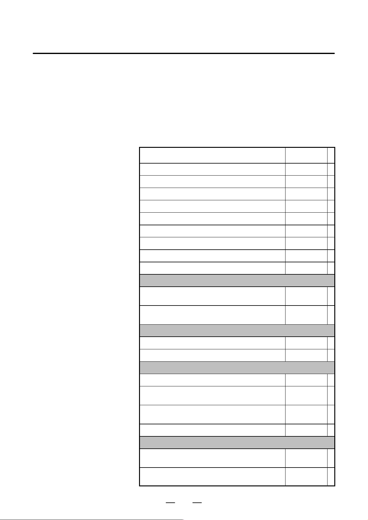
The following table lists the manuals related to Series 0i–B and 0i
Mate–B. This manual is indicated by an asterisk(*).
Manual name
DESCRIPTIONS B–63832EN
CONNECTION MANUAL (HARDWARE) B–63833EN
CONNECTION MANUAL (FUNCTION) B–63833EN–1
Series 0i–TB OPERATOR’S MANUAL B–63834EN
Series 0i–MB OPERA T OR’S MANUAL B–63844EN *
Series 0i Mate–TB OPERATOR’S MANUAL B–63854EN
Series 0i Mate–MB OPERA T OR’S MANUAL B–63864EN
Specification
number
MAINTENANCE MANUAL B–63835EN
P ARAMETER MANUAL B–63840EN
Programming
Macro Compiler/Macro Executor
PROGRAMMING MANUAL
FANUC MACRO COMPILER (For Personal Computer)
PROGRAMMING MANUAL
PMC
PMC Ladder Language PROGRAMMING MANUAL B–61863E
PMC C Language PROGRAMMING MANUAL B–61863E–1
Network
PROFIBUS–DP Board OPERA T OR’S MANUAL B–62924EN
Ethernet Board/DA T A SERVER Board
OPERATOR’S MANUAL
FAST Ethernet Board/FAST DA TA SERVER
OPERATOR’S MANUAL
DeviceNet Board OPERA T OR’S MANUAL B–63404EN
B–61803E–1
B–66102E
B–63354EN
B–63644EN
OPEN CNC
FANUC OPEN CNC OPERATOR’S MANUAL
Basic Operation Package 1 (For Windows 95/NT)
FANUC OPEN CNC OPERATOR’S MANUAL
(DNC Operation Management Package)
4
B–62994EN
B–63214EN

B–63844EN/02
GENERAL
1. GENERAL
Related manuals of
Servo Motor ai series
Related manuals of
Servo Motor b series
The following table lists the manuals related to Servo Motor ai series.
Manual name
FANUC AC SER VO MOTOR ai series DESCRIPTIONS B–65262EN
FANUC AC SER VO MOTOR ai series
P ARAMETER MANUAL
FANUC AC SPINDLE MOT OR ai series DESCRIPTIONS B–65272EN
FANUC AC SPINDLE MOT OR ai series
P ARAMETER MANUAL
FANUC SER VO AMPLIFIER ai series DESCRIPTIONS B–65282EN
FANUC SER VO MOT OR ai series
MAINTENANCE MANUAL
Specification
number
B–65270EN
B–65280EN
B–65285EN
The following table lists the manuals related to Servo Motor b series.
Manual name
FANUC SER VO MOT OR b series DESCRIPTIONS B–65232EN
FANUC SER VO MOT OR b series
MAINTENANCE MANUAL
Specification
number
B–65235EN
FANUC SER VO MOT OR b series(I/O Link Option)
DESCRIPTIONS
B–65245EN
5
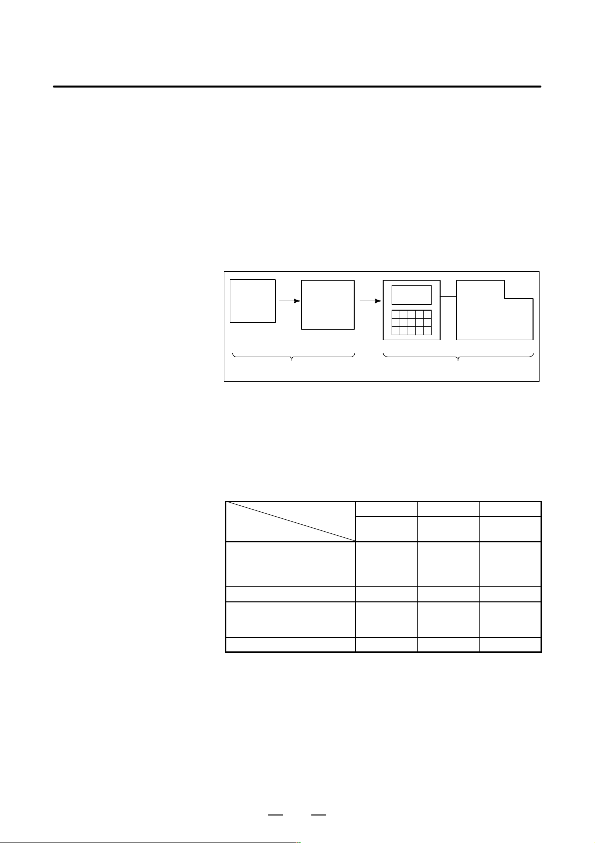
GENERAL1. GENERAL
B–63844EN/02
1.1 GENERAL FLOW OF OPERA TION OF CNC MACHINE TOOL
When machining the part using the CNC machine tool, first prepare the
program, then operate the CNC machine by using the program.
1) First, prepare the program from a part drawing to operate the CNC
machine tool.
How to prepare the program is described in the Chapter II.
PROGRAMMING.
2) The program is to be read into the CNC system. Then, mount the
workpieces and tools on the machine, and operate the tools according
to the programming. Finally, execute the machining actually.
How to operate the CNC system is described in the Chapter III.
OPERATION.
Part
drawing
CHAPTER II PROGRAMMING CHAPTER III OPERATION
Part
programming
CNC
MACHINE TOOL
Before the actual programming, make the machining plan for how to
machine the part.
Machining plan
1. Determination of workpieces machining range
2. Method of mounting workpieces on the machine tool
3. Machining sequence in every machining process
4. Machining tools and machining
Decide the machining method in every machining process.
Machining process
Machining procedure
1. Machining method
: Rough
Semi
Finish
2. Machining tools
3. Machining conditions
: Feedrate
Cutting depth
4. Tool path
1 2 3
Feed cutting Side cutting
Hole
machining
6
 Loading...