


USER INSTRUCTIONS
AND
TECHNICAL INSTRUCTIONS
FE-24E // FE-27E
EC-TYPE EXAMINATION CERTIFICATE
PIN0099BN794 (FE-24E)
PIN0099BO808 (FE-27E)
BOILER OUTPUT
N51J015F1-00
The compliance with a British Standard does not, of itself, confer immunity from legal obligations. In particular the installation of this appliance must be in accordance with the relevant requirements of the Gas Safety(Installation and Use) Regulations 1984 as amended, current IEE Wiring Regulations, local Building Regulations, Building Standards (Scotland)(Consolidation) and byelaws of the local Water Company. Health and Safety Document No. 635 (Electricity at Work Regulation). It should in accordance with the relevant recommendations of the following British Standards.
BS 6798:1987 Specifications for installation of gas fired hot water boilers of rated input not exceeding 60 kW BS 5449:1990 Central Heating for Domestic Premises.
BS 5546:1990 Installation for gas hot water supplies for domestic purposes.
BS 5440:1990 Flues and Ventilation for gas appliances of rated input not exceeding 60 kW: Flues.
BS 5440:1990 Flues and Ventilation for gas appliances of rated input not exceeding 60 kW: Air Supply. BS 6891:1988 Installation of low pressure gas pipework installations up to 28 mm (R1)
To ensure that the installation will perform to the highest standards, the system and components should conform to any other relevant British Standards in addition to those mentioned in the instructions.
The appliance is not suitable for external installation.
2

USER INDEX
|
|
|
|
|
|
|
|
|
|
|
|
|
|
|
|
|
|
|
|
|
|
|
|
|
|
|
|
|
|
|
|
|
|
|
|
|
|
|
|
|
|
Pág. |
|
1.- CONTROL PANEL |
4 |
||||||||||||||||||||||||||||||||||||||||||
2.- PREPARING THE BOILER FOR SERVICE |
|
|
|
|
|
|
|
|
|
|
|
|
|
|
|
|
|
|
|
4 |
|||||||||||||||||||||||
|
|
|
|
|
|
|
|
|
|
|
|
|
|
||||||||||||||||||||||||||||||
3.- USER INSTRUCTIONS |
|
|
|
|
|
|
|
|
|
|
|
|
|
|
|
|
|
|
|
|
|
|
|
|
|
|
|
|
5 |
||||||||||||||
|
|
|
|||||||||||||||||||||||||||||||||||||||||
4.- MAINTENANCE |
|
|
|
|
|
|
|
|
|
|
|
|
|
|
|
|
|
|
|
|
|
|
|
|
|
|
|
|
|
|
|
5 |
|||||||||||
|
|
|
|
||||||||||||||||||||||||||||||||||||||||
5.- PRECAUTION AGAINST FREEZING |
6 |
||||||||||||||||||||||||||||||||||||||||||
6.- ANTI PUMP SEIZURE DEVICE |
|
|
|
|
|
|
|
|
|
|
|
|
|
|
|
|
|
|
|
6 |
|||||||||||||||||||||||
|
|
|
|
|
|
||||||||||||||||||||||||||||||||||||||
7.- FAULT CODES |
6 |
||||||||||||||||||||||||||||||||||||||||||
INSTALLER INDEX |
|
|
|
|
|
|
|
|
|
|
|
|
|
|
|
|
|
||||||||||||||||||||||||||
8.- HOMOLOGATION CERTIFICATE |
7 |
||||||||||||||||||||||||||||||||||||||||||
9.- DESCRIPTION OF THE APPLIANCE |
8 |
||||||||||||||||||||||||||||||||||||||||||
*Principal components |
8 |
||||||||||||||||||||||||||||||||||||||||||
*Operation and safety controls |
8 |
||||||||||||||||||||||||||||||||||||||||||
10.-TECHNICAL DATA |
9 |
||||||||||||||||||||||||||||||||||||||||||
11.-FUNCTIONAL DIAGRAMS |
|
|
|
|
|
|
|
|
|
|
|
|
|
|
|
|
|
|
|
|
10 |
||||||||||||||||||||||
|
|
|
|
|
|
||||||||||||||||||||||||||||||||||||||
*Gas and water system |
10 |
||||||||||||||||||||||||||||||||||||||||||
*Electrical circuit diagrams |
10 |
||||||||||||||||||||||||||||||||||||||||||
12.-DIMENSIONS AND CONNECTION DETAILS |
|
|
|
|
|
|
|
|
|
|
|
|
11 |
||||||||||||||||||||||||||||||
|
|
|
|
|
|
||||||||||||||||||||||||||||||||||||||
13.-HYDRAULIC SYSTEM CHARACTERISTICS |
|
|
|
|
|
|
|
|
|
|
11 |
||||||||||||||||||||||||||||||||
|
|
|
|
|
|
||||||||||||||||||||||||||||||||||||||
*Domestic hot water |
11 |
||||||||||||||||||||||||||||||||||||||||||
*Central heating |
11 |
||||||||||||||||||||||||||||||||||||||||||
14.-INSTALLATION OF THE BOILER |
12 |
||||||||||||||||||||||||||||||||||||||||||
15.-Ø 60-100 mm HORIZONTAL CONCENTRIC COMBUSTION PRODUCT EXTRACTION AND |
|
|
|
|
|
|
|
|
|
|
|
|
|
|
|
|
|
||||||||||||||||||||||||||
AIR INTAKE |
|
|
|
|
|
|
|
|
|
|
|
|
|
|
|
|
|
|
|
13 |
|||||||||||||||||||||||
|
|
|
|
|
|||||||||||||||||||||||||||||||||||||||
16.-Ø 80-125 mm HORIZONTAL CONCENTRIC COMBUSTION PRODUCT EXTRACTION AND |
|
|
|
|
|
|
|
|
|
|
|
|
|
|
|
|
|
||||||||||||||||||||||||||
AIR INTAKE |
|
|
|
|
|
|
|
|
|
|
|
|
|
|
|
|
14 |
||||||||||||||||||||||||||
|
|
||||||||||||||||||||||||||||||||||||||||||
17.-Ø 80 mmTWIN-PIPE COMBUSTION PRODUCT EXTRACTION AND AIR INTAKE |
15 |
||||||||||||||||||||||||||||||||||||||||||
18.-80-125 mm VERTICAL CONCENTRIC COMBUSTION PRODUCT EXTRACTION AND AIR |
|
|
|
|
|
|
|
|
|
|
|
|
|
|
|
|
|
||||||||||||||||||||||||||
INTAKE. |
16 |
||||||||||||||||||||||||||||||||||||||||||
19.-ELECTRICAL CONNECTIONS |
|
|
|
|
|
|
|
|
|
17 |
|||||||||||||||||||||||||||||||||
|
|
|
|
|
|||||||||||||||||||||||||||||||||||||||
*Connection of a room thermostat (optional) |
17 |
||||||||||||||||||||||||||||||||||||||||||
20.-CONTROL PANEL |
17 |
||||||||||||||||||||||||||||||||||||||||||
21.-PREPARING THE BOILER FOR SERVICE |
18 |
||||||||||||||||||||||||||||||||||||||||||
22.- USER INSTRUCTIONS |
18 |
||||||||||||||||||||||||||||||||||||||||||
23.-MAINTENANCE |
|
|
|
|
|
|
|
|
|
|
19 |
||||||||||||||||||||||||||||||||
|
|
|
|
|
|||||||||||||||||||||||||||||||||||||||
24.-PRECAUTION AGAINST FREEZING |
20 |
||||||||||||||||||||||||||||||||||||||||||
25.-ANTI PUMP SEIZURE DEVICE |
|
|
|
|
|
20 |
|||||||||||||||||||||||||||||||||||||
|
|
||||||||||||||||||||||||||||||||||||||||||
26.-GAS CHANGE |
21 |
||||||||||||||||||||||||||||||||||||||||||
27.-FAULT CODES |
22 |
||||||||||||||||||||||||||||||||||||||||||
28.-FAULT FINDING |
|
|
|
|
23 |
||||||||||||||||||||||||||||||||||||||
|
|
||||||||||||||||||||||||||||||||||||||||||
USER
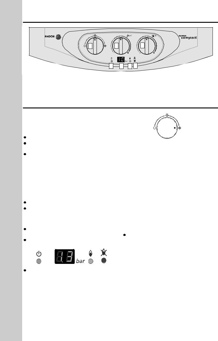
.- CONTROL PANEL
|
FE-24E |
3 |
2 |
5 |
1 |
6 |
7 |
- |
Display |
5.- Boiler ON indicator light |
- Heating temperature selector |
6.- Burner on indicator light |
|
- D.H |
temperature selector |
7.- Reset indicator light |
-control switch and reset
.- COMMISSIONING THE
VERY IMPORTANT: before |
the |
boiler on |
|
Domestic hot water |
|
|
|
Turn |
the cold water stopcock beneath |
boiler. |
|
Fill |
unit by turning on the |
hot water taps |
|
in the installation. |
|
|
|
|
sure that the assembly is |
|
airtight |
and watertight. |
|
|
|
 The installation of a scale reducer/water softener is recommended in water areas
 To increase the hot water temperature, reduce the
flow of water at the hot water tap. This |
be nec- |
||
essary |
winter months. |
|
|
|
heating system |
|
|
The correct installation is to be |
out |
follows: |
|
|
radiator air vents. |
|
|
With |
stopcock on and |
domestic |
water |
going through to the boiler, fill the central heating sys-
tem |
opening |
filling tap |
provided |
your |
|||
|
air vents off once water starts coming out |
||||||
of |
them. |
|
|
|
|
|
|
|
the filling tap when the |
gauge |
|||||
|
the |
of 1.3 bar. |
1.5 |
. |
|||
|
|
|
|
|
|
|
|
|
|
|
|
|
|
|
|
|
|
|
|
|
|
|
|
|
|
|
|
|
|
|
|
|
|
|
|
|
|
|
|
|
|
|
|
|
|
|
|
 Vent the central heating system once more. Then let the pressure in the system settle at 1.3 bar. Max = 1.5 bar..
 Make sure that there are no leaks in the installation.
 Make sure that the heating system is completely full and vented. The pressure gauge should show between 1.3 and 1.5 bar with cold water in the heating system.
 Make sure that the boiler is wired to the correct voltage.
 Make sure that the combustion flue outlet is not restricted.
Gas circuit
 Turn on the gas stopcock to the installation.
 Check that the whole gas circuit and gas connections to the boiler are airtight.
Settings
the boiler is pre-set in accordance with the information on the adhesive data plate, and therefore needs no further adjustment. Should the type of gas need to be changed, check with the corresponding section.
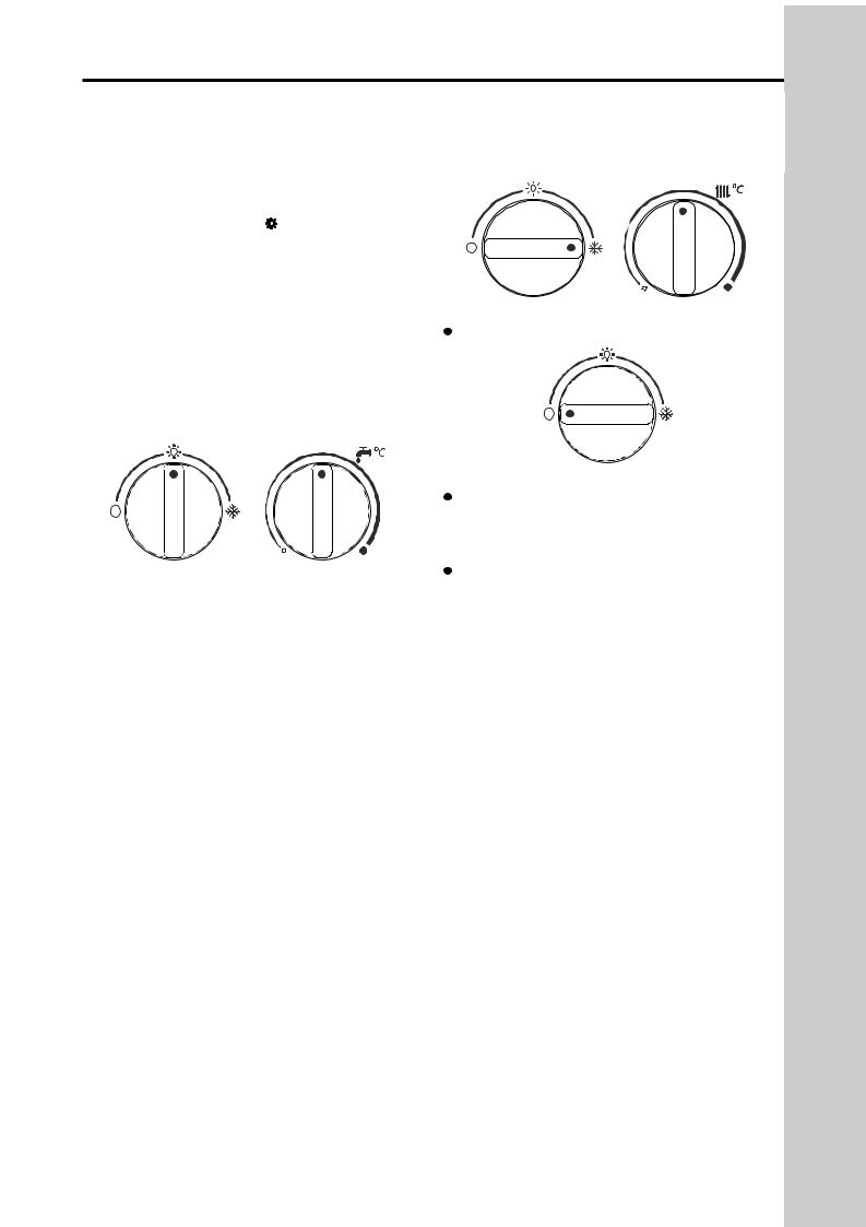
By turning the main control switch to the winter setting  . When the pump works the pressure in the digital display increases.
4
3.- INSTRUCTIONS
Check the gas connections and make sure that the gas is coming into the boiler (that the gas tap is open)
Make sure that the heating system is completely full and vented. The pressure gauge should show between 1.3 and 1.5 bar with cold water in the heating system.
Make sure that the electricity supply to the boiler is switched on.
Domestic |
water service. |
|
|
order to turn the |
on , see the figure below |
|
|
will be ready |
|
domestic hot water whenever |
|
there is a demand for |
|
||
When you |
on |
of the hot taps the boiler will |
Switching off the |
|
come |
with the pilot light switching on |
|
|
Turn the main switch the setting O. |
||
first of all followed by the burner. A water temperature |
|||
the domestic hot |
temperature regulating knob. |
|
|
When the D |
.W. |
temperature regulating knob is |
|
temperature.
Hot water and central heating service.
Turn the switch to the winter setting  . The burner will automatically fire up if the clock and/or the roomthermostat are calling for heat. A temperature of between 60° and 85° C can be selected by turning the heating temperature regulating knob. This will stay on until it achieves the temperature selected either in the room thermostat or in the boiler itself.
Whenever domestic hot water is required when it is at the central heating setting, the boiler is designed to give priority to the supply of domestic hot water, with the central heating on hold, until the demand for domestic hot water ceases. When the D.H.W. temperature regulating knob is turned the digital display will show the values of the temperature.
Reset of the boiler.
This unit has a built-in reset indicator. Whenever any fault is detected in the ignition process, the boiler goes to lock out and the reset indicator switches on and the fault code is shown in the display.
the main switch to position O. The reset indicator should then turn off.
When the system pressure either falls down to 0.6 bar or goes over 2.8 bar, the display will shown F-3. needs to fill it up to 1.3-1.5 bar (when system cold).
IMPORTANT: If the boiler has not been used for a length of time, or a new gas bottle is connected, the unit could lock out due to the presence of air in the pipes. Should this happen, the ignition procedure should be repeated until the gas circuit is cleared of all air in the gas supply.
USER
5
USER
4 - FROST PROTECTION
The boiler has an frost protection security system.
IMPORTANT: the boiler must be electrically supplied and gas connected for this to operate.
Frost protection
When the heating thermistor detects a temperature of 6ºC, only the pump will switch and will continue to run
until a temperature of 9ºC |
obtained. |
If the temperature drops |
3ºC, the boiler will start on |
minimum power until |
temperature of 20ºC is |
obtained. |
|
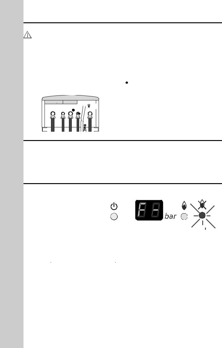
NOTE: If the boiler is not to be used for a long period drain the heating installation using the valve (Z) beneath the boiler and D.H.W. installation.
The D.H.W circuit must be drained down as follows:
 Turn off the cold water supply.
 Open all the hot water outlet taps in the installation (at least one tap should be found at a level lower than the boiler).
 Release the tap to drain the flow switch to allow air to come in and for the stored water in the boiler to be able to leave.(see figure)
 When the operation is finished, close the hot water outlet taps and the draining tap.
boiler back into service, open the cold water inlet tap.
 Z
Z
5.- ANTI PUM SEIZURE DEVICE
When the boiler is not being used, the pump will auto- |
If the pump jammed when the appliance is turned |
matically run for one minute every 24 hours to pre- |
back on, consult your installer or service engineer. |
vent seizure. TO ENSURE OPERATION OF THIS |
|
DEVICE ELECTRICAL SUPPLIES MUST BE ON. |
|
|
|
6.- FAULT CODES
Should a fault develop within the boiler (diagnostic), the P.C.B. will diagnose the possible cause via the reset indicator light (Red Neon) and the digital display. The fault will be shown in the display.
lowed by a number. Ranging from 1 - 13. To reset the fault use the reset switch (4) (see Control Panel page 4)
|
|
NUMBER OF 1 SEC |
FAULT |
|
|
‘FLASHES’ |
|
|
|
|
|
|
|
|
|
|
|
|
Lack of gas or ignition problems; Flame |
|
1 |
|
supervision failure |
|
|
|
Burner on but flame Indicator Off; H L |
|
2 |
|
Air Pressure Switch Failure |
|
|
|
|
|
|
|
If the central heating pressure drops |
|
3 |
|
below 0.6 bar or gets above 2.8 bar , |
|
|
|
the boiler goes to lock out |
|
4 |
|
The overheat thermostat blocks out the |
|
|
boiler |
|
|
|
|
6

7.- CERTIFICATE
INSTALLER

 Loading...