


 Loading...
CNC 101/102(S)
New Features (Version 0110 in)

ERRORS DETECTED IN THE INSTALLATION MANUAL (REF. 9703)
Comparison table (page x). General characteristics.
In the "Axes" section" where it says "Axes X + Y + Auxiliary handwheel"
It should say "X Axis + Auxiliary Y axis (not dro) + Auxiliary handwheel"
Comparison table (page xii). Programming.
The programming function G34 is missing:
G34 X axis as an infinite follower of another axis (only for the 101S)
Section 2.3.4 (chapter 2 page 8). Table below.
Digits 7 and 8 are backwards. They should be like this:
Digit |
Corresponding Input |
Pin |
8 |
External feedrate override 1 |
10 (I/O1) |
7 |
External feedrate override 2 |
11 (I/O1) |
6 |
X axis feedback error |
|
5 |
Y axis feedback error |
|
4 |
X axis sine-wave feedback alarm |
|
3 |
Y axis sine-wave feedback alarm |
|
2 |
Over-temperature |
|
1 |
Not being used at this time |
|
Section 3.5 (chapter 3 page 8). Feedback alarm parameter P22(7), P62(7)
The last paragraph is wrong, it should read:
"If the feedback system ....... with a value of "0" (feedback alarm OFF)".
Section 4.4.2 (chapter 4 page 13). Open positioning loop
The first paragraph is wrong, it should say:
It is necessary to set P23(4)=0.
Appendix "F" (page 9). I/O related parameters
The first line is wrong, it should read:
P22(7),P62(7) |
Feedback alarm ON (1) or OFF (0) on the X, Y axis (respectively). |
P63(6) |
The probe is active high, P63(6)=0, or low, P63(6)=1. |
Appendix "G" (page 12). P22(7)
It is wrong, it should read:
P22(7) Feedback alarm ON (1) or OFF (0) on the X axis.
Appendix "G" (page 13). P62(7)
It is wrong, it should read:
P62(7) Feedback alarm ON (1) or OFF (0) on the Y axis.
P63(6) The probe is active high, P63(6)=0, or low, P63(6)=1.
MODIFICATIONS TO THE INSTALLATION MANUAL (REF. 9703)
Section 1.6.1 (chapter 1 page 11). RESET
The last paragraph should read:
When setting machine parameter "P30" with a value other than "0", the CNC behaves as follows: A leading edge (up flank) interrupts the execution and it is redirected to a HOME block, but the HOME function is not executed until a trailing edge (down flank) is detected.
Section 1.8.1 (chapter 1 page 22). External keys without the "JOG 100" keypad (jog box)
Connection example using only the external control keys "X+", "X-"
Section 4.1.1.1 (chapter 4 page 11). P63(1) Acceleration/deceleration in all G01 movements
It should read:
P63(1) Acceleration/deceleration also on linear interpolations (G01)
It defines if the CNC, besides applying acc/dec ramps (P16, P17, P91, P92) on all rapid movements at F0, it also applies them on linear interpolations (G01).
0= Only on rapid movements (G00) and at F0.
1= On rapid movements and on all linear interpolations (G01).
- 2 -
MODIFICATIONS TO THE OPERATION MANUAL (REF. 9703)
Section 2.3.4 (chapter 2 page 8). Table below. |
|
Digit |
Corresponding Input |
Pin |
||||||||||||||||||||||||||||||
Digits 7 and 8 are backwards. They should be like this: |
|
|
|
|
||||||||||||||||||||||||||||||
|
8 |
External feedrate override 1 |
10 (I/O1) |
|||||||||||||||||||||||||||||||
|
|
|
|
|
|
|
|
|
|
|
|
|
|
|
|
|
|
|
|
|
|
|
|
|
|
|
|
|
|
|
|
7 |
External feedrate override 2 |
11 (I/O1) |
|
|
|
|
|
|
|
|
|
|
|
|
|
|
|
|
|
|
|
|
|
|
|
|
|
|
|
|
|
|
|
|
6 |
X axis feedback error |
|
|
|
|
|
|
|
|
|
|
|
|
|
|
|
|
|
|
|
|
|
|
|
|
|
|
|
|
|
|
|
|
|
|||
|
|
|
|
|
|
|
|
|
|
|
|
|
|
|
|
|
|
|
|
|
|
|
|
|
|
|
|
|
|
|
|
5 |
Y axis feedback error |
|
|
|
|
|
|
|
|
|
|
|
|
|
|
|
|
|
|
|
|
|
|
|
|
|
|
|
|
|
|
|
|
|
|||
|
|
|
|
|
|
|
|
|
|
|
|
|
|
|
|
|
|
|
|
|
|
|
|
|
|
|
|
|
|
|
|
4 |
X axis sine-wave feedback alarm |
|
|
|
|
|
|
|
|
|
|
|
|
|
|
|
|
|
|
|
|
|
|
|
|
|
|
|
|
|
|
|
|
|
|||
|
|
|
|
|
|
|
|
|
|
|
|
|
|
|
|
|
|
|
|
|
|
|
|
|
|
|
|
|
|
|
|
|
|
|
|
|
|
|
|
|
|
|
|
|
|
|
|
|
|
|
|
|
|
|
|
|
|
|
|
|
|
|
|
|
|
|
3 |
Y axis sine-wave feedback alarm |
|
|
|
|
|
|
|
|
|
|
|
|
|
|
|
|
|
|
|
|
|
|
|
|
|
|
|
|
|
|
|
|
|
|||
|
|
|
|
|
|
|
|
|
|
|
|
|
|
|
|
|
|
|
|
|
|
|
|
|
|
|
|
|
|
|
|
2 |
Over-temperature |
|
|
|
|
|
|
|
|
|
|
|
|
|
|
|
|
|
|
|
|
|
|
|
|
|
|
|
|
|
|
|
|
|
1 |
Not being used at this time |
|
Section 6.5.4 (chapter 6 page 17). Synchronism (G33)
In the printing example.
*If the turning of the roller is controlled with an external device, it is not necessary to program the " N0 S1000 M3" block, but machine parameter P36 must be set to the approximate rpm of the roller.
*If the roller does not have an encoder, because no controlled synchronism is needed, pin 5 of connector A2 must be connected to 5V.
Software Version 2.02 (May 1998)
1. ASSUME X1 OF THE HANDWHEEL WITH THE "JOG 100" JOG BOX
Machine parameter P102(7) indicates whether the axes can be jogged or not with the handwheel when the Feedrate Override Switch is positioned out of the handwheel markings while using the "JOG 100" jog box and the JOG mode is selected.
P102(7) = 0 It is not possible. The handwheel is active in the handwheel positions only.
P102(7) = 1 The handwheel is active in any position of the Feedrate Override Switch.
When machine parameter P102(7) = 1, the CNC applies the "x1" factor when the switch is positioned out of the handwheel positions.
2. THE CNC101 ALSO HAS ARITHMETIC PROGRAMMING.
From this version on, the CNC101 model also has arithmetic programming with conditional jumps (G26, G27, G28, G29).
|
|
|
101 |
101S |
102 |
102S |
Arithmetic programming |
|
|
x |
x |
x |
x |
|
|
|
|
|
|
|
Arithmetic parameters |
|
|
100 |
100 |
100 |
100 |
PROGRAMMING |
G26 |
Jump if zero |
x |
x |
x |
x |
FUNCTIONS |
G27 |
Jump if not zero |
x |
x |
x |
x |
|
G28 |
Jump if less than zero |
x |
x |
x |
x |
|
G29 |
Jump if equal or greater than zero |
x |
x |
x |
x |
|
|
|
|
|
|
|
3. AXES NOMENCLATURE.
With bits 1 and 2 of parameter P102, the axes nomenclature may be defined.
P102(2) |
P102(1) |
Axes Nomenclature |
0 |
0 |
X Y |
0 |
1 |
Y C |
1 |
0 |
X Z |
1 |
1 |
Y Z |
The new denomination selected only affects the display, they will keep being X and Y internally. Therefore, when accessing the CNC via DNC 100, the axes will always be X Y.
4. MOVEMENTS IN G75
In previous versions, when a movement programmed in G75 reached position and the CNC had not yet received the probe signal, the CNC would issue error 21.
From this version on, parameter P102(5) indicates whether the CNC issues error 21 or not.
P102(5) = 0 It issues error 21. Like until now.
P102(5) = 1 It does not issue error 21. It goes on executing the next block.
- 3 -

5. DISPLAY OF THE AXIS IN EXECUTION
In previous versions, while in Automatic mode, the CNC could change the axis being displayed depending on the movement programmed:
If both axes move |
=> |
it keeps displaying the axis selected with A+ ,A- |
If only the X axis moves |
=> |
it displays the X axis |
If only the Y axis moves |
=> |
it displays the Y axis |
From this version on, parameter P102(6) determines whether the CNC behaves like before or it does not change the axis being displayed.
P102(6) = 0 |
Like before |
P102(6) = 1 |
The CNC does not change the axis. It keeps displaying the axis selected with A+ ,A- |
Software Version 2.03 (January 1999)
1. ADDITIONAL MOVEMENT WITH G75
When probing at high speed, it could stop abruptly making the axis overshoot the programmed position and having to move back into position.
In previous versions of the CNC 101 S, machine parameter P82 could be used to minimize this sometimes undesirable effect.
This parameter indicates to the CNC the distance the axis must move after receiving the probe signal, thus stopping smoothly.
From this version on, this feature will also be available on the "102 S" CNC model and parameter P83 indicates the distance the Y axis must move after receiving the probe signal.
Therefore: |
P82 |
indicates the distance the X axis must move after receiving the probe signal. |
|
|
P83 |
indicates the distance the Y axis must move after receiving the probe signal. |
|
|
Possible values: |
From 1 to 65535 microns. |
|
|
|
|
From 1 to 25801 tenth-thousandths of an inch. |
Software Version 2.05 (October 2001)
1.OPERATION WITH 100-LINE HANDWHEELS (U.F.O.)
Until now, the CNC 101/102 was ready to operate with 25-line handwheels. It internally multiplies by 4 in order to obtain 100 pulses per each turn of the handwheel.
From this version on, it is also possible to use 100-line handwheels (Fagor UFO model handwheels) Set machine parameter P103(2)=1 so its pulses are not multiplied by 4.
This feature is only available when connecting the handwheel to the CNC's feedback input.
The auxiliary handwheel, connected to the digital inputs of the CNC must always have 25 lines per turn.
Headquarters (SPAIN): Fagor Automation S. Coop.
Bº San Andrés s/n, Apdo. 144 E-20500 Arrasate - Mondragón Tel: (34)-943 71 92 00
Fax: (34)-943 79 17 12
(34)-943 77 11 18 (Service Dept.) www.fagorautomation.com
E-mail: info@fagorautomation.es
- 4 -
FAGOR 101 / 101S CNC FAGOR 102 / 102S CNC
INSTALLATION MANUAL
Ref. 9703 (ing)

The information described in this manual may be subject to variations due to technical modifications.
FAGOR AUTOMATION, S. Coop. Ltda. reserves the right to modify the contents of this manual without prior notice.

INDEX
Section |
|
|
Page |
|
Comparison table for FAGOR CNC models: 101/101S/102/102S ................................. |
ix |
|
|
New Features and Modifications ..................................................................................... |
xiii |
|
|
INTRODUCTION |
|
|
|
Declaration of Conformity ............................................................................................ |
3 |
|
|
Safety Conditions ........................................................................................................... |
4 |
|
|
Warranty Terms |
.............................................................................................................. |
7 |
|
Material Returning Terms ............................................................................................. |
8 |
|
|
Additional Remarks ....................................................................................................... |
9 |
|
|
Fagor Documentation ..........................................for the 101/101S/ 102/102S CNC |
10 |
|
|
Manual Contents ............................................................................................................ |
11 |
|
|
Chapter 1 |
CNC CONFIGURATION |
|
1.1 |
Dimensions and ............................................................................................installation |
1 |
|
1.2 |
Connectors and interface ................................................................................................. |
2 |
|
1.3 |
Connectors A1, A2 .......................................................................................................... |
4 |
|
1.3.1 |
Dip-switches for ................................................................................connectors A1, A2 |
5 |
|
1.4 |
RS232C Connector ......................................................................................................... |
6 |
|
1.5 |
RS485 Connector ............................................................................................................ |
9 |
|
1.5.1 |
Recommended cable ................................................................................for the RS485 |
9 |
|
1.6 |
Connector I/O 1 ............................................................................................................... |
|
10 |
1.6.1 |
Inputs of connector .................................................................................................I/O 1 |
11 |
|
1.6.2 |
Outputs of connector ..............................................................................................I/O 1 |
14 |
|
1.7 |
Connector I/O 2 ............................................................................................................... |
|
16 |
1.7.1 |
Inputs of connector .................................................................................................I/O 2 |
17 |
|
1.7.2 |
Outputs of connector ..............................................................................................I/O 2 |
19 |
|
1.8 |
External operator .................................................................................panel "JOG 100" |
20 |
|
1.8.1 |
External keys without .........................................................."JOG 100" Operator Panel |
22 |
|

Section |
|
|
Page |
|
Chapter 2 |
POWER AND MACHINE INTERFACE |
|
2.1 |
Power interface ................................................................................................................ |
|
1 |
2.2 |
Machine interface ............................................................................................................ |
2 |
|
2.2.1 |
General considerations .................................................................................................... |
2 |
|
2.2.2 |
Digital outputs................................................................................................................. |
|
4 |
2.2.3 |
Digital inputs ................................................................................................................... |
|
4 |
2.2.4 |
Analog outputs ................................................................................................................ |
|
5 |
2.2.5 |
Feedback inputs............................................................................................................... |
|
5 |
2.3 |
Set-up............................................................................................................................... |
|
6 |
2.3.1 |
General considerations .................................................................................................... |
6 |
|
2.3.2 |
Precautions ...................................................................................................................... |
|
6 |
2.3.3 |
Connection ...................................................................................................................... |
|
7 |
2.3.4 |
System I/O test ................................................................................................................. |
|
8 |
2.4 |
Emergency input/output connection .............................................................................. |
11 |
|
|
Chapter 3 |
MACHINE PARAMETERS |
|
3.1 |
Introduction |
..................................................................................................................... |
1 |
3.2 |
Operation with parameter tables ...................................................................................... |
2 |
|
3.3 |
General machine ............................................................................................parameters |
3 |
|
3.4 |
Machine parameters .....................................................................for axis configuration |
5 |
|
3.5 |
I/O related parameters ...................................................................................................... |
8 |
|
3.6 |
Operating mode .................................................................................related parameters |
11 |
|
3.7 |
Programming ...........................................................................mode related parameters |
13 |
|
3.8 |
Execution mode ................................................................................related parameters |
15 |
|
|
Chapter 4 |
MACHINE PARAMETERS FOR THE AXES |
|
4.1 |
Parameters related to axis resolution ............................................................................... |
2 |
|
4.1.1 |
Feedback correction factor for the axes ........................................................................... |
3 |
|
4.2 |
Parameters related to the analog outputs ......................................................................... |
5 |
|
4.3 |
Feedrate related parameters ............................................................................................. |
6 |
|
4.4 |
Parameters related to the positioning loop ...................................................................... |
8 |
|
4.4.1 |
Closed loop |
..................................................................................................................... |
9 |
4.4.1.1 |
Parameters related to acceleration/deceleration .............................................................. |
10 |
|
4.4.2 |
Open loop ........................................................................................................................ |
|
13 |
4.5 |
Parameters related ....................................................................................to axis control |
15 |
|
4.6 |
Parameters related ..................................................................to machine reference zero |
17 |
|
4.7 |
Parameters related ...................................................................................to travel limits |
19 |
|
4.8 |
Leadscrew related ..........................................................................................parameters |
20 |
|
4.9 |
Special machine ............................................................................................parameters |
21 |
|

Section |
|
|
Page |
|
Chapter 5 |
OTHER MACHINE PARAMETERS |
|
5.1 |
Spindle machine parameters ............................................................................................ |
1 |
|
5.1.1 |
Parameters related to the spindle speed output ............................................................... |
2 |
|
5.2 |
Parameters related to the serial line RS232C .................................................................. |
4 |
|
5.3 |
Parameters related to the Fagor Local Area Network (LAN) ............................................ |
5 |
|
5.4 |
Parameters related to double feedback ............................................................................ |
7 |
|
5.5 |
Parameters related to function G34 ................................................................................. |
8 |
|
5.6 |
Parameters related to function G75 ................................................................................. |
9 |
|
5.7 |
Parameters related to function G47, G48 ......................................................................... |
10 |
|
5.8 |
Parameters related to function G60 ................................................................................. |
11 |
|
|
Chapter 6 |
CONCEPTS |
|
6.1 |
Feedback system |
.............................................................................................................. |
1 |
6.1.1 |
Counting frequency limitation ........................................................................................ |
2 |
|
6.2 |
Axis resolution ................................................................................................................ |
|
3 |
6.3 |
Adjustment of the axes .................................................................................................... |
11 |
|
6.3.1 |
Adjustment of the drift (offset) and maximum feedrate (G00) ......................................... |
12 |
|
6.4 |
Control of the axis positioning loop ............................................................................... |
13 |
|
6.4.1 |
Closed positioning loop .................................................................................................. |
14 |
|
6.4.1.1 |
Proportional gain adjustment .......................................................................................... |
15 |
|
6.4.1.2 |
Calculation of K1, K2 and gain break-point ................................................................... |
16 |
|
6.4.1.3 |
Feed-Forward gain adjustment ........................................................................................ |
18 |
|
6.4.1.4 |
Closed loop with brake.................................................................................................... |
19 |
|
6.4.2 |
Non-servo-controlled open positioning loop .................................................................. |
20 |
|
6.4.3 |
Servo-controlled open positioning loop ......................................................................... |
22 |
|
6.5 |
Reference systems............................................................................................................ |
24 |
|
6.5.1 |
Reference points |
.............................................................................................................. |
24 |
6.5.2 |
Machine Reference (home) search ................................................................................... |
25 |
|
6.5.3 |
Adjustment of the machine reference point (home) ........................................................ |
26 |
|
6.5.4 |
Software travel limit for the axes ..................................................................................... |
27 |
|
6.5.5 |
Considerations about the machine reference point ......................................................... |
27 |
|
6.6 |
Auxiliary M function....................................................................................................... |
28 |
|
6.7 |
Spindle............................................................................................................................. |
|
29 |
6.7.1 |
Spindle speed range change ............................................................................................ |
31 |
|
6.8 |
Tools ................................................................................................................................ |
|
31 |
6.9 |
M, S, T function transfer .................................................................................................. |
32 |
|
6.9.1 |
M, S, T function transfer using the FEEDHOLD signal ................................................... |
33 |
|
|
Chapter 7 |
FAGOR LOCAL AREA NETWORK |
|
7.1 |
Introduction ..................................................................................................................... |
|
1 |
7.2 |
LAN interface .................................................................................................................. |
|
2 |
7.3 |
CNC configuration in the FAGOR LAN .......................................................................... |
5 |
|
7.4 |
Internal CNC information ................................................................................................ |
7 |
|
7.4.1 |
Direct reading of the internal CNC variables from a PLC64 ........................................... |
8 |
|
7.4.2 |
Direct writing of the internal CNC variables from a PLC64 ............................................ |
10 |
|
7.4.3 |
Access to the arithmetic parameters of the CNC from a PLC64 ...................................... |
12 |
|
7.4.4 |
Access to the internal CNC variables from an 8020, 8025 or 8030 CNC ....................... |
13 |
|
7.4.4.1 |
Access to the internal "READ" variables ......................................................................... |
13 |
|
7.4..4.2 |
Access to the internal "WRITE" variables ....................................................................... |
15 |
|
7.4.4.3 |
Access to the internal "READ-WRITE" variables ........................................................... |
17 |
|
7.5 |
Execution commands of this CNC programmable at an 8020, 8025 or 8030 CNC ........ |
17 |
|

Section |
|
|
Page |
|
Chapter 8 |
DNC COMMUNICATIONS PROTOCOL |
|
8.1 |
Basic concepts |
................................................................................................................. |
1 |
8.2 |
Codes to read CNC data .................................................................................................. |
3 |
|
8.3 |
Codes to write data into the CNC .................................................................................... |
8 |
|
8.4 |
Codes to execute ...................................................................................program blocks |
10 |
|
|
APPENDICES |
|
A |
Technical characteristics of the CNC .............................................................................. |
2 |
B |
Enclosures ....................................................................................................................... |
5 |
C |
Circuits recommended for probe connection .................................................................. |
6 |
D |
CNC inputs and outputs .................................................................................................. |
7 |
E |
2-digit BCD coded "S" output conversion table ............................................................. |
8 |
F |
Machine parameter summary chart .................................................................................. |
9 |
G |
Sequential machine parameter list ................................................................................... |
12 |
H |
Machine parameter setting chart ..................................................................................... |
15 |
I |
Key codes ........................................................................................................................ |
16 |
J |
Maintenance .................................................................................................................... |
17 |
ERROR CODES
COMPARISON TABLE FOR FAGOR CNC MODELS: 101/101S/102/102S
GENERAL CARACTERISTICS
|
|
101 |
101S |
102 |
102S |
Feedback inputs |
Connector A1 (X axis) |
x |
x |
x |
x |
|
Connector A2 (Y axis) |
|
x |
x |
x |
|
x5 multiplier circuit for sine-wave signals |
|
x |
x |
x |
|
|
|
|
|
|
|
Feedback correction factor |
x |
x |
x |
x |
Analog outputs |
X axis |
x |
x |
x |
x |
|
Y axis |
|
|
x |
x |
|
Spindle (S) |
x |
x |
x |
x |
|
|
|
|
|
|
Axes |
X axis |
x |
x |
x |
x |
|
X + Y axis |
|
|
x |
x |
|
X axis + electronic handwheel |
|
x |
x |
x |
|
Axes X + Y + auxiliary handwheel |
|
x |
x |
x |
|
Double feedback for X axis |
|
x |
|
|
|
|
|
|
|
|
Axis control |
Closed Loop |
x |
x |
x |
x |
|
Open Loop |
x |
|
x |
|
|
Rigid Tapping |
|
|
|
x |
Interface with external |
External operator panel "JOG 100" |
|
x |
|
x |
devices |
|
|
|
|
|
RS232C Interface |
|
x |
x |
x |
|
|
|
||||
|
Fagor Local Area Network (LAN) |
|
x |
x |
x |
|
DNC 100 |
|
x |
|
x |
Operating options |
Overtemperature alarm |
|
x |
x |
x |
|
Operation in radius or diameter |
|
x |
x |
x |
|
Operation with a probe |
|
x |
x |
x |
|
Zero offsets |
|
x |
x |
x |
|
Tool length compensation |
|
x |
x |
x |
|
Acceleration / deceleration |
x |
x |
x |
x |

INPUTS AND OUTPUTS
|
|
101 |
101S |
102 |
102S |
INPUTS |
X axis home switch |
x |
x |
x |
x |
|
Y axis home switch |
|
x |
x |
x |
|
External emergency stop |
x |
x |
x |
x |
|
Feedhold |
x |
x |
x |
x |
|
External Cycle Start |
x |
x |
x |
x |
|
External Cycle Stop |
x |
x |
x |
x |
|
Conditional input (block skip) |
x |
x |
x |
x |
|
Manual input (DRO mode) |
x |
x |
x |
x |
|
External Reset (initial CNC conditions) |
x |
x |
x |
x |
|
2 inputs as Handwheel multiplying factor |
|
JOG100 |
x |
JOG100 |
|
2 inputs for Feedrate override |
|
JOG100 |
x |
JOG100 |
|
5 inputs for parametric programming |
|
x |
x |
x |
|
2 inputs for handling the auxiliary handwheel |
|
x |
x |
x |
OUTPUTS |
8 outputs for M, S or T in BCD or decoded |
x |
x |
x |
x |
|
M Strobe |
x |
x |
x |
x |
|
S Strobe |
|
x |
x |
x |
|
T Strobe |
|
x |
x |
x |
|
JOG mode selected at the CNC |
x |
x |
x |
x |
|
Automatic mode selected at the CNC |
|
x |
x |
x |
|
Internal CNC emergency |
x |
x |
x |
x |
|
X axis brake |
x |
x |
x |
x |
|
Y axis brake |
|
|
x |
x |
|
X axis in position |
x |
x |
x |
x |
|
Y axis in position |
|
|
x |
x |
|
X axis Fast (Non-servocontrolled open loop) |
x |
JOG 100 |
x |
JOG 100 |
|
X axis Slow (Non-servocontrolled open loop) |
x |
JOG 100 |
x |
JOG 100 |
|
X direction (Non-servocontrolled open loop) |
x |
JOG 100 |
x |
JOG 100 |
|
Y axis Fast (Non-servocontrolled open loop) |
|
JOG 100 |
x |
JOG 100 |
|
Y axis Slow (Non-servocontrolled open loop) |
|
|
x |
|
|
Y direction (Non-servocontrolled open loop) |
|
|
x |
|
PROGRAMMING
|
|
|
101 |
101S |
102 |
102S |
Number of blocks |
|
|
900 |
900 |
900 |
900 |
Conditional blocks (block skip) |
|
x |
x |
x |
x |
|
Parts counter |
|
|
x |
x |
x |
x |
Arithmetic programming |
|
|
x |
x |
x |
|
Arithmetic parameters |
|
|
100 |
100 |
100 |
|
|
|
|
|
|
|
|
PROGRAMMI |
G00 |
Rapid positioning |
x |
x |
x |
x |
FUNCTIONS |
G01 |
Linear interpolation |
x |
x |
x |
x |
|
G02 |
Clockwise circular interpolation |
|
|
x |
x |
|
G03 |
Counter-clockwise circular interpolation |
|
|
x |
x |
|
G04 |
Dwell |
x |
x |
x |
x |
|
G05 |
Round corner |
x |
x |
x |
x |
|
G07 |
Square corner |
x |
x |
x |
x |
|
G25 |
Unconditional jump |
x |
x |
x |
x |
|
G26 |
Jump if zero |
|
x |
x |
x |
|
G27 |
Jump if not zero |
|
x |
x |
x |
|
G28 |
Jump if less than zero |
|
x |
x |
x |
|
G29 |
Jump if equal or greater than zero |
|
x |
x |
x |
|
G33 |
Synchronization |
|
x |
|
|
|
G45 |
Increment part-counter's count |
x |
x |
x |
x |
|
G47 |
Pulse inhibit |
|
x |
x |
x |
|
G48 |
Cancel function G47 |
|
x |
x |
x |
|
G51 to G60 |
Load zero offset |
|
x |
x |
x |
|
G61 |
F not affected by "P18" |
x |
x |
x |
x |
|
G62 |
Cancel function G61 |
x |
x |
x |
x |
|
G70 |
Inch programming |
x |
x |
x |
x |
|
G71 |
Metric programming |
x |
x |
x |
x |
|
G74 |
Machine Reference (home) search |
x |
x |
x |
x |
|
G75 |
Probing |
|
x |
x |
x |
|
G81 |
Batch programming |
|
x |
|
x |
|
G84, G80 |
Rigid tapping |
|
|
|
x |
|
G90 |
Absolute coordinate programming |
x |
x |
x |
x |
|
G91 |
Incremental coordinate programming |
x |
x |
x |
x |
|
G92 |
Coordinate presetting |
x |
x |
x |
x |
|
G93 |
Modification of acceleration ramp |
|
x |
x |
x |

NEW FEATURES
AND
MODIFICATIONS
|
|
|
|
|
|
|
Date: |
March 1997 |
Software Version: 2.1 and newer |
|
|
|
FEATURE |
AFFECTED MANUAL AND SECTION |
|
||
|
|
|
|
|
|
|
Synchronization of movements (G33) |
Operating Manual |
Section 6.5.4 |
|
|
|
|
|
|
|
|
|
Axis X as infinite slave of another axis (G34) |
InstallationManual |
Section 5.5 |
|
|
|
|
|
Operating Manual |
Section 6.5.5 |
|
|
|
|
|
|
|
|
G47, G48 as axis loop opener |
InstallationManual |
Section 5.7 |
|
|
|
|
|
Operating Manual |
Section 6.7.2 |
|
|
|
|
|
|
|
|
G75 special function |
InstallationManual |
Section 5.6 |
|
|
|
|
|
|
|
|
|
Travel limit control taking into account the |
InstallationManual |
Section 5.8 |
|
|
|
the punch radius |
Operating Manual |
Section 6.8.4 |
|
|
|
|
|
|
|
|
|
Selection of the Arithmetical Parameters |
InstallationManual |
Section 3.7 |
|
|
|
which are required for display. |
Operating Manual |
Section 6.9.3 |
|
|
|
|
|
|
|
|
|
Play-Back, as reading points. |
InstallationManual |
Section 3.6 |
|
|
|
|
|
Operating Manual |
Section 4.3.1 |
|
|
|
|
|
|
|
|
Parametrical programming takes the S |
Installation Manual |
Sect. 5.1 and 6.7 |
|
|
|
sign into account |
|
|
|
|
|
|
|
|
|
|
|
The axes can be denominated Y, C |
InstallationManual |
Section 3.4 |
|
|
|
Auxiliary Handwheel handling by |
Installation Manual |
Sect. 1.7, 3.4 and |
|
|
|
means of 2 digital inputs |
Operating Manual |
Section 3.1 |
|
|
|
|
|
|
|
|
|
Braking Control in open loop |
InstallationManual |
Section 4.4.2 |
|
|
|
|
|
|
|
|
|
Reading / Writing of machine parameters |
|
|
|
|
|
from the DNC100 |
|
|
|
|
|
|
|
|
|
|
|
Error elimination by external Reset. |
|
|
|
|
|
|
|
|
|
|
|
|
|
|
|
|

INTRODUCTION
Attention:
Before starting up the CNC, carefully read the instructions of Chapter 2 in the Installation Manual.
The CNC must not be powered-on until verifying that the machine complies with the "89/392/CEE" Directive.
Introduction - 1

DECLARATION OF CONFORMITY
Manufacturer: Fagor Automation, S. Coop.
Barrio de San Andrés s/n, C.P. 20500, Mondragón -Guipúzcoa- (ESPAÑA)
We hereby declare, under our responsibility that the product:
Fagor 101/101S / 102/102S CNC
meetsthefollowingdirectives:
SAFETY:
EN 60204-1 Machine safety. Electrical equipment of the machines.
ELECTROMAGNETIC COMPATIBILITY:
EN 50081-2 |
Emission |
EN 55011 |
Radiated. Class A, Group 1. |
EN 55011 |
Conducted. Class A, Group 1. |
EN 61000-3-2 |
CurrentHarmonics |
EN 61000-3-3 |
Voltagefluctuationsandflickers |
EN 50082-2 Immunity |
|
EN 61000-4-2 |
ElectrostaticDischarges. |
EN 61000-4-3 |
Radiofrequency Radiated Electromagnetic Fields. |
EN 61000-4-4 |
Bursts and fast transients. |
EN 61000-4-5 |
Conducted high voltage pulses in mains (Surges) |
EN 61000-4-6 |
Conducted disturbance induced by radio frequency fields. |
EN 61000-4-8 |
Magnetic fields at mains frequency |
EN 61000-4-11 |
Voltage fluctuations and Outages. |
ENV 50204 |
Fields generated by digital radio-telephones |
As instructed by the European Community Directives: on Low Voltage 73/23/CEE, on Machine Safety 89/392/EEC, 89/336/EEC on Electromagnetic Compatibility and its upgrades.
In Mondragón, on October 1st, 2001
Introduction - 3

SAFETY CONDITIONS
Read the following safety measures in order to prevent damage to personnel, to this product and to those products connected to it.
This unit must only be repaired by personnel authorized by Fagor Automation.
Fagor Automation shall not be held responsible for any physical or material damage derived from the violation of these basic safety regulations.
Precautions against personal damage
Use proper Mains AC power cables
To avoid risks, use only the Mains AC cables recommended for this unit.
Avoid electrical overloads
In order to avoid electrical discharges and fire hazards, do not apply electrical voltage outside the range selected on the rear panel of the Central Unit.
Ground connection
In order to avoid electrical discharges, connect the ground terminals of all the modules tothemaingroundterminal.Beforeconnectingtheinputsandoutputsofthisunit,make sure that all the grounding connections are properly made.
Before powering the unit up, make sure that it is connected to ground
In order to avoid electrical discharges, make sure that all the grounding connections are properly made.
Do not work in humid environments
In order to avoid electrical discharges, always work under 90% of relative humidity (non-condensing) and 45º C (113º F).
Do not work in explosive environments
In order to avoid risks, damage, do not work in explosive environments.
Precautions against product damage
Working environment
This unit is ready to be used in Industrial Environments complying with the directives and regulations effective in the European Community
Fagor Automation shall not be held responsible for any damage suffered or caused when installed in other environments (residential or homes).
Install the unit in the right place
Itisrecommended,wheneverpossible,toinstaltheCNCawayfromcoolants,chemical product, blows, etc. that could damage it.
This unit complies with the European directives on electromagnetic compatibility. Nevertheless, it is recommended to keep it away from sources of electromagnetic disturbance such as.
Introduction - 4
-Powerful loads connected to the same AC power line as this equipment.
-Nearby portable transmitters (Radio-telephones, Ham radio transmitters).
-Nearby radio / TC transmitters.
-Nearby arc welding machines
-Nearby High Voltage power lines
-Etc.
Enclosures
The manufacturer is responsible of assuring that the enclosure involving the equipment meets all the currently effective directives of the European Community.
Avoid disturbances coming from the machine tool
The machine-tool must have all the interference generating elements (relay coils, contactors, motors, etc.) uncoupled.
Use the proper power supply
Use an external regulated 24 Vdc power supply for the inputs and outputs.
Grounding of the power supply
The zero volt point of the external power supply must be connected to the main ground point of the machine.
Analog inputs and outputs connection
It is recommended to connect them using shielded cables and connecting their shields (mesh) to the corresponding pin (See chapter 2).
Ambient conditions
The working temperature must be between +5° C and +45° C (41ºF and 113º F) The storage temperature must be between -25° C and 70° C. (-13º F and 158º F)
Monitor enclosure
Assure that the Monitor is installed at the distances indicated in chapter 1 from the walls of the enclosure.
Use a DC fan to improve enclosure ventilation.
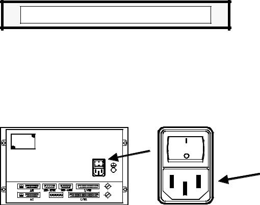
Main AC Power Switch
This switch must be easy to access and at a distance between 0.7 m (27.5 inches) and 1.7 m (5.6 ft) off the floor.
Protections of the unit itself
It carries two fast fuses of 3.15 Amp./ 250V. to protect the mains AC input.
All the digital inputs and outputs have galvanic isolation via optocouplers between the CNC circuitry and the outside.
They are protected by an external fast fuse (F) of 3.15 Amp./ 250V. against over voltage and reverse connection of the power supply.
The type of fuse depends on the type of monitor. See the identification label of the unit.
Introduction - 5
Precautions during repair
Do not manipulate the inside of the unit
Only personnel authorized by Fagor Automation may manipulate the inside of this unit.
Do not manipulate the connectors with the unit connected to AC power.
Before manipulating the connectors (inputs/outputs, feedback, etc.) make sure that the unit is not connected to AC power.
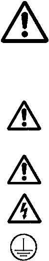
Safety symbols
Symbols which may appear on the manual
WARNING. symbol
It has an associated text indicating those actions or operations may hurt people or damage products.
Symbols that may be carried on the product
WARNING. symbol
It has an associated text indicating those actions or operations may hurt people or damage products.
"Electrical Shock" symbol
It indicates that point may be under electrical voltage
"Ground Protection" symbol
It indicates that point must be connected to the main ground point of the machine as protection for people and units.
Introduction - 6
WARRANTY TERMS
WARRANTY
All products manufactured or marketed by Fagor Automation has a warranty period of 12 months from the day they are shipped out of our warehouses.
The mentioned warranty covers repair material and labor costs, at FAGOR facilities, incurred in the repair of the products.
Within the warranty period, Fagor will repair or replace the products verified as being defective.
FAGOR is committed to repairing or replacing its products from the time when the first such product was launched up to 8 years after such product has disappeared from the product catalog.
It is entirely up to FAGOR to determine whether a repair is to be considered under warranty.
EXCLUDING CLAUSES
The repair will take place at our facilities. Therefore, all shipping expenses as well as travelling expenses incurred by technical personnel are NOT under warranty even when the unit is under warranty.
This warranty will be applied so long as the equipment has been installed according to the instructions, it has not been mistreated or damaged by accident or negligence and has been manipulated by personnel authorized by FAGOR.
If once the service call or repair has been completed, the cause of the failure is not to be blamed the FAGOR product, the customer must cover all generated expenses according to current fees.
No other implicit or explicit warranty is covered and FAGOR AUTOMATION shall not be held responsible, under any circumstances, of the damage which could be originated.
SERVICE CONTRACTS
Service and Maintenance Contracts are available for the customer within the warranty period as well as outside of it.
Introduction - 7

MATERIAL RETURNING TERMS
When returning the CNC, pack it in its original package and with its original packaging material. If not available, pack it as follows:
1.- Get a cardboard box whose three inside dimensions are at least 15 cm (6 inches) larger than those of the unit. The cardboard being used to make the box must have a resistance of 170 Kg (375 lb.).
2.- When sending it to a Fagor Automation office for repair, attach a label indicating the owner of the unit, person to contact, type of unit, serial number, symptom and a brief description of the problem.
3.- Wrap the unit in a polyethylene roll or similar material to protect it.
When sending the monitor, especially protect the CRT glass.
4.- Pad the unit inside the cardboard box with poly-utherane foam on all sides.
5.- Seal the cardboard box with packing tape or industrial staples.
Introduction - 8
ADDITIONAL REMARKS
*Mount the CNC away from coolants, chemical products, blows, etc. which could damage it.
*Before turning the unit on, verify that the ground connections have been properly made. See Section 2.2 of this manual.
*To prevent electrical shock use the proper mains AC connector at the Power Supply Module. Use 3-wire power cables (one for ground connection)
*In case of a malfunction or failure, disconnect it and call the technical service. Do not manipulate inside the unit.
Introduction - 9
FAGOR DOCUMENTATION
FOR THE 101/101S / 102/102S CNC
101/101S / 102/102S CNC OEM Manual
Is directed to the machine builder or person in charge of installing and starting up the CNC.
It has the Installation manual inside. Sometimes, it may contain an additional manual describing New Software Features recently implemented.
101/101S / 102/102S CNC USER Manual
Is directed to the end user or CNC operator.
It contains the Operating manual.
Sometimes, it may contain an additional manual describing New Software
Features recently implemented.
Introduction - 10
MANUAL CONTENTS
The installation manual consists of the following sections:
Index
Comparative Table for Fagor 101/101S / 102/102S CNC models
Introduction |
|
Warning sheet prior to start-up |
|
|
Declaration of Conformity |
|
|
Safety Conditions |
|
|
Warranty terms |
|
|
Shipping conditions |
|
|
Additional remarks |
|
|
Fagor documents for the 101/101S / 102/102S CNC |
|
|
Manual Contents |
Chapter 1 |
CNC configuration |
|
|
|
Indicates the Central Unit dimensions |
|
|
Detailed description of all the connectors. |
Chapter 2 |
Power and machine connection. |
|
|
|
Indicates how to connect it to Main AC power. |
|
|
Ground connection. |
|
|
Characteristics of the digital inputs and outputs. |
|
|
Characteristics of the analog output. |
|
|
Characteristics of the feedback inputs |
|
|
CNC setup and start-up |
|
|
System I/O testing |
|
|
Connection of the Emergency input and output. |
Chapter 3, 4, 5 |
Machine parameters. |
|
|
|
How to operate with machine parameters. |
|
|
How to set the machine parameters. |
|
|
Detailed description of the general machine parameters. |
Chapter 6 |
Concepts. |
|
|
|
Feedback systems, resolution |
|
|
Adjustment of the axes and their gains. |
|
|
Reference Systems: Reference systems, search and setting |
|
|
Acceleration / deceleration. |
|
|
Spindle: speed control and range change. |
|
|
Tools and tool magazine |
|
|
Auxiliary M, S, T function transfer |
Chapter 7 |
Local Area Network |
|
|
|
Indicates how to connect an operate the Fagor LAN |
Chapter 8 |
DNC communications protocol |
|
Appendix |
A |
CNC technical characteristics. |
|
B |
Enclosures. |
|
C Circuits recommended for probe connection |
|
|
D CNC inputs and outputs. |
|
|
E 2-digit BCD coded spindle "S" output |
|
|
F Machine parameter summary chart |
|
|
G Sequential machine parameter listing |
|
|
H |
Machine parameter setting chart |
|
I |
Key codes |
|
J |
Maintenance |
Error Codes
Introduction - 11

1. CNC CONFIGURATION
Attention:
The CNC is prepared to be used in Industrial Environments, especially on milling machines, lathes, etc. It can control machine movements and devices.
It can control machine movements and devices.
1.1DIMENSIONS AND INSTALLATION
This FAGOR CNC is usually mounted on the operator panel of the machine by means of the 4 mounting holes provided on the front panel of the CNC.
The appendix at the end of this manual shows the necessary dimensions of the enclosure where this CNC will be installed guaranteeing its proper ambient conditions.
Chapter: 1 |
Section: |
Page |
|
CNC CONFIGURATION |
DIMENSIONS AND |
1 |
|
INSTALLATION |
|||
|
|
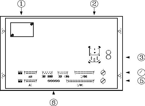
1.2CONNECTORS AND INTERFACE
|
|
|
|
|
|
|
|
|
|
|
|
|
|
|
|
|
|
|
|
|
|
|
|
|
|
|
|
|
|
|
|
|
|
|
|
|
|
|
|
|
|
|
|
|
|
|
|
|
|
|
|
|
|
|
|
|
|
|
|
|
|
|
|
|
|
|
|
|
|
|
|
|
|
|
|
|
|
|
|
|
|
|
|
|
|
|
|
|
|
|
|
|
|
|
|
|
|
|
|
|
|
|
|
|
|
|
|
|
|
|
|
|
|
|
|
|
|
|
|
|
|
|
|
|
|
|
|
|
|
|
|
|
|
|
|
|
|
|
|
|
|
|
|
|
|
|
|
|
|
|
|
|
|
|
|
|
|
|
|
|
|
|
|
|
|
|
|
|
|
|
|
|
|
|
|
|
|
|
|
|
|
|
|
|
|
|
|
|
|
|
|
|
|
|
|
|
|
|
|
|
|
|
|
|
|
|
|
|
|
|
|
|
|
|
|
|
|
|
|
|
|
|
|
|
|
|
|
|
|
|
|
|
|
|
|
|
|
|
|
|
|
|
|
|
|
|
|
|
|
|
|
|
|
|
|
|
|
|
|
|
|
|
|
|
|
|
|
|
|
|
|
|
|
|
|
|
|
|
|
|
|
|
|
|
|
|
|
|
|
|
|
|
|
|
|
|
|
|
|
|
|
|
|
|
|
|
|
|
|
|
|
|
|
|
|
|
|
|
|
|
|
|
|
|
|
|
|
|
|
|
|
|
|
|
|
|
|
|
|
|
|
|
|
|
|
|
|
|
|
|
|
|
|
|
|
|
|
|
|
|
|
|
|
|
|
|
|
|
|
|
|
|
|
|
|
|
|
|
|
|
|
|
|
|
|
|
|
|
|
|
|
|
|
|
|
|
|
|
|
|
|
|
|
|
|
|
|
|
|
|
|
|
|
|
|
|
|
|
|
|
|
|
|
|
|
|
|
|
|
|
|
|
|
|
|
|
|
|
|
|
|
|
|
|
|
|
|
|
|
|
|
|
|
|
|
|
|
|
|
|
|
|
|
|
|
|
|
|
|
|
|
|
|
|
|
|
|
|
|
|
|
|
|
|
|
|
|
|
|
|
|
|
|
|
|
|
|
|
|
|
|
|
|
|
|
|
|
|
|
|
|
|
|
|
|
|
|
|
|
|
|
|
|
|
|
|
|
|
|
|
|
|
|
|
|
|
|
|
|
|
|
|
|
|
|
|
|
|
|
|
|
|
|
|
|
|
|
|
|
|
|
|
|
|
|
|
|
|
|
|
|
|
|
|
|
|
|
|
|
|
|
|
|
|
|
|
|
|
|
|
|
|
|
|
|
|
|
|
|
|
|
|
|
|
|
|
|
|
|
|
|
|
|
|
|
|
|
|
|
|
|
|
|
|
|
|
|
|
|
|
|
|
|
|
|
|
|
|
|
|
|
|
|
|
|
|
|
|
|
|
|
|
|
|
|
|
|
|
|
|
|
|
|
|
|
|
|
|
|
|
|
|
|
|
|
|
|
|
|
|
|
|
|
|
|
|
|
|
|
|
|
|
|
|
|
|
|
|
|
|
|
|
|
|
|
|
|
|
|
|
|
|
|
|
|
|
|
|
|
|
|
|
|
|
|
|
|
|
|
|
|
|
|
|
|
|
|
|
|
|
|
|
|
|
|
|
|
|
|
|
|
|
|
|
|
|
|
|
|
|
|
|
|
|
|
|
|
|
|
|
|
|
|
|
|
|
|
|
|
|
|
|
|
|
|
|
|
|
|
|
|
|
|
|
|
|
|
|
|
|
|
|
|
|
|
|
|
|
|
|
|
|
|
|
|
|
|
|
|
|
|
|
|
|
|
|
|
|
|
|
|
|
|
|
|
|
|
|
|
|
|
|
|
|
|
|
|
|
|
|
|
|
|
|
|
|
|
|
|
|
|
|
|
|
|
|
|
|
|
|
|
|
|
|
|
|
|
|
|
|
|
|
|
|
|
|
|
|
|
|
|
|
|
|
|
|
|
|
|
|
|
|
|
|
|
|
|
|
|
|
|
|
|
|
|
|
|
|
|
|
|
|
|
|
|
|
|
|
|
|
|
|
|
|
|
|
|
|
|
|
|
|
|
|
|
|
|
|
|
|
|
|
|
|
|
|
|
|
|
|
|
|
|
|
|
|
|
|
|
|
|
|
|
|
|
|
|
|
|
|
|
|
|
|
|
|
|
|
|
|
|
|
|
|
|
|
|
|
|
|
|
|
|
|
|
|
|
|
|
|
|
|
|
|
|
|
|
|
|
|
|
|
|
|
|
|
|
|
|
|
|
|
|
|
|
|
|
|
|
|
|
|
|
|
|
|
|
|
|
|
|
|
|
|
|
|
|
|
|
|
|
|
|
|
|
|
|
|
|
|
|
|
|
|
|
|
|
|
|
|
|
|
|
|
|
|
|
|
|
|
|
|
|
|
|
|
|
|
|
|
|
|
|
|
|
|
|
|
|
|
|
|
|
|
|
|
|
|
|
|
|
|
|
|
|
|
|
|
|
|
|
|
|
|
|
|
|
|
|
|
|
|
|
|
|
|
|
|
|
|
|
|
|
|
|
|
|
|
|
|
|
|
|
|
|
|
|
|
|
|
|
|
|
|
|
|
|
|
|
|
|
|
|
|
|
|
|
|
|
|
|
|
|
|
|
|
|
|
|
|
|
|
|
|
|
|
|
|
|
|
|
|
|
|
|
|
|
|
|
|
|
|
|
|
|
|
|
|
|
|
|
|
|
|
|
|
|
|
|
|
|
|
|
|
|
|
|
|
|
|
|
|
|
|
|
|
|
|
|
|
|
|
|
|
|
|
|
|
|
|
|
|
|
|
|
|
|
|
|
|
|
|
|
|
|
|
|
|
|
|
|
|
|
|
|
|
|
|
|
|
|
|
|
|
|
|
|
|
|
|
|
|
|
|
|
|
|
|
|
|
|
|
|
|
|
|
|
|
|
|
|
|
|
|
|
|
|
|
|
|
|
|
|
|
|
|
|
|
|
|
|
|
|
|
|
|
|
|
|
|
|
|
|
|
|
|
|
|
|
|
|
|
|
|
|
|
|
|
|
|
|
|
|
|
|
|
|
|
|
|
|
|
|
|
|
|
|
|
|
|
|
|
|
|
|
|
|
|
|
|
|
|
|
|
|
|
|
|
|
|
|
|
|
|
|
|
|
|
|
|
|
|
|
|
|
|
|
|
|
|
|
|
|
|
|
|
|
|
|
|
|
|
|
|
|
|
|
|
|
|
|
|
|
|
|
|
|
|
|
|
|
|
|
|
|
|
|
|
|
|
|
|
|
|
|
|
|
|
|
|
|
|
|
|
|
|
|
|
|
|
|
|
|
|
|
|
|
|
|
|
|
|
|
|
|
|
|
|
|
|
|
|
|
|
|
|
|
|
|
|
|
|
|
|
|
|
|
|
|
|
|
|
|
|
|
|
|
|
|
|
|
|
|
|
|
|
|
|
|
|
|
|
|
|
|
|
|
|
|
|
|
|
|
|
|
|
|
|
|
|
|
|
|
|
|
|
|
|
|
|
|
|
|
|
|
|
|
|
|
|
|
|
|
|
|
|
|
|
|
|
|
|
|
|
|
|
|
|
|
|
|
|
|
|
|
|
|
|
|
|
|
|
|
|
|
|
|
|
|
|
|
|
|
|
|
|
|
|
|
|
|
|
|
|
|
|
|
|
|
|
|
|
|
|
|
|
|
|
|
|
|
|
|
|
|
|
|
|
|
|
|
|
|
|
|
|
|
|
|
|
|
|
|
|
|
|
|
|
|
|
|
|
|
|
|
|
|
|
|
|
|
|
|
|
|
|
|
|
|
|
|
|
|
|
|
|
|
|
|
|
|
|
|
|
|
|
|
|
|
|
|
|
|
|
|
|
|
|
|
|
|
|
|
|
|
|
|
|
|
|
|
|
|
|
|
|
|
|
|
|
|
|
|
|
|
|
|
|
|
|
|
|
|
|
|
|
|
|
|
|
|
|
|
|
|
|
|
|
|
|
|
|
|
|
|
|
|
|
|
|
|
|
|
|
|
|
|
|
|
|
|
|
|
|
|
|
|
|
|
|
|
|
|
|
|
|
|
|
|
|
|
|
|
|
|
|
|
|
|
|
|
|
|
|
|
|
|
|
|
|
|
|
|
|
|
|
|
|
|
|
|
|
|
|
|
|
|
|
|
|
|
|
|
|
|
|
|
|
|
|
|
|
|
|
|
|
|
|
|
|
|
|
|
|
|
|
|
|
|
|
|
|
|
|
|
|
|
|
|
|
|
|
|
|
|
|
|
|
|
|
|
|
|
|
|
|
|
|
|
|
|
|
|
|
|
|
|
|
|
|
|
|
|
|
|
|
|
|
|
|
|
|
|
|
|
|
|
|
|
|
|
|
|
|
|
|
|
|
|
|
|
|
|
|
|
|
|
|
|
|
|
|
|
|
|
|
|
|
|
|
|
|
|
|
|
|
|
|
|
|
|
|
|
|
|
|
|
|
|
|
|
|
|
|
|
|
|
|
|
|
|
|
|
|
|
|
|
|
|
|
|
|
|
|
|
|
A1 |
|
15-pin SUB-D type female connector for X axis feedback connection. |
||||||||||||||||||||||||||||||||||||||||||||||||||||||||||||||||||||||||||||||||||||||
|
|
|
|
|
|
|
It admits sine-wave signals. |
|||||||||||||||||||||||||||||||||||||||||||||||||||||||||||||||||||||||||||||||||
A2 |
|
15-pin SUB-D type female connector for Y axis feedback connection. |
||||||||||||||||||||||||||||||||||||||||||||||||||||||||||||||||||||||||||||||||||||||
|
|
|
|
|
|
|
It admits sine-wave signals. |
|||||||||||||||||||||||||||||||||||||||||||||||||||||||||||||||||||||||||||||||||
RS232C |
|
9-pin SUB-D type female connector for RS-232C serial line connection. |
||||||||||||||||||||||||||||||||||||||||||||||||||||||||||||||||||||||||||||||||||||||
RS485 |
|
9-pin SUB-D type female connector for RS-485 serial line connection. |
||||||||||||||||||||||||||||||||||||||||||||||||||||||||||||||||||||||||||||||||||||||
I/O1 |
|
37-pin SUB-D type female connector to interface with the electrical cabinet. |
||||||||||||||||||||||||||||||||||||||||||||||||||||||||||||||||||||||||||||||||||||||
I/O2 |
|
25-pin SUB-D type female connector to interface with the electrical cabinet. |
||||||||||||||||||||||||||||||||||||||||||||||||||||||||||||||||||||||||||||||||||||||
1Lithium battery. See appendix in this manual.
2Mains, A.C. power plug and switch. To power the CNC by connecting it through a transformer and ground.
3Ground terminal. Metric 6mm. Where the general machine ground must be connected.
4, 5 |
Fuses. 3.15Amp./250V fast fuses (F) to protect the internal I/O circuitry of the |
|
CNC. |
Page |
Chapter: 1 |
Section: |
|
2 |
CNC CONFIGURATION |
CONNECTORS AND |
|
INTERFACE |
|||
|
|
||
|
|
|

6Potentiometers for analog output adjustment. ONLY to be used by the Technical Service Department at FAGOR AUTOMATION.
SM (symmetry), G (gain), OF1 (X axis offset), OF2 (Y axis offset), OF3 (spindle offset).
Attention:
Do not manipulate inside this unit
Only personnel authorized by Fagor Automation may manipulate inside this module.
Do not manipulate the connectors with the unit connected to main AC power
Before manipulating these connectors, make sure that the unit is not connected to main AC power.
Chapter: 1 |
Section: |
Page |
|
CNC CONFIGURATION |
CONNECTORS AND |
3 |
|
INTERFACE |
|||
|
|
||
|
|
|

1.3CONNECTORS A1, A2
They are 15-pin SUB-D type female connectors used to connect feedback devices.
The feedback system must be metric. Which means that each feedback pulse must be assigned a non-decimal distance value in microns. For example, when a 0.0001 inch/pulse resolution is desired, its equivalent metric value of 2.54µm/pulse cannot be set. This problem may be solved by using inch-pitch encoders (635 lines/rev., 1270 lines/rev. etc.) or the feedback correcting factor described later on in this manual.
*Connector A1 is used for the X axis feedback signals.
*Connector A2 is used for the feedback signals from the Y axis or from the electronic handwheel.
The type of cable used must have overall shield. The rest of its characteristics such as length will depend on the type and model of the feedback device being used.
It is highly recommended to run these cables as far away as possible from the power cables of the machine.
PIN |
|
|
|
|
|
MEANING AND FUNCTION |
|
|
|
|
|
|
|
1 |
|
|
A |
|
||
2 |
|
|
A |
Differential square-wave feedback signals. |
||
3 |
|
|
B |
|
||
4 |
|
|
B |
|
|
|
|
|
|
|
|
|
|
5 |
|
|
Io |
Machine reference pulse (Marker) |
||
6 |
|
|
Io |
|
|
|
|
|
|
|
|
|
|
7 |
|
|
Ac |
Sine-wave feedback signals. |
||
8 |
|
|
Bc |
|
||
|
|
|
|
|
|
|
9 |
|
|
+5V. |
Power to feedback device. |
||
10 |
|
|
|
|
|
Not connected. |
11 |
|
|
0V. |
Power to feedback device. |
||
12 |
|
|
|
|
|
Not connected. |
13 |
|
|
-5V. |
Power to feedback device. |
||
14 |
|
|
|
|
|
Not connected. |
|
|
|
|
|
|
|
15 |
|
CHASSIS |
Shield. |
|||
|
|
|
|
|
|
|
Attention:
The output signals of square-wave rotary encoders must be TTL compatible and no Open Collector output signals may be used.
When using a touch probe, pin 5 of connector A2 should be used as input for the probe signal.
The appendix at the end of this manual shows a few recommended circuits for probe connection.
If this pin is also used for the Y axis marker pulse (home), an auxiliary "M" function may be used to switch the two signals.
Page |
Chapter: 1 |
Section: |
4 |
CNC CONFIGURATION |
CONNECTORS A1, A2 |
|
|
|
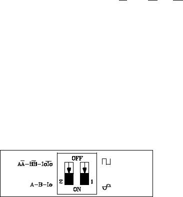
1.3.1DIP-SWITCHES FOR CONNECTORS A1, A2
There are 2 dip-switches next to each feedback input connector (A1, A2) to set the CNC according to the type of feedback signal being used in each case.
Dip-switch 1 indicates whether the feedback signal is sine-wave or square-wave and dipswitch 2 indicates whether the feedback signal is differential (double-ended) or not (singleended).
The feedback signals that can be used at connectors A1 and A2 are:
*Sine-wave feedback signals (Ac, Bc, Io)
*Square-wave feedback signals (A, B, Io)
* Differential square-wave feedback signals ( A, A, B, B, Io, Io)
The chart below shows the dip-switch combinations for the particular type of feedback signal used at each feedback input:
Dip-switch |
MEANING AND FUNCTION |
||||||||
1 |
|
2 |
|
|
|
|
|
|
|
|
|
|
|
|
|
|
|
||
ON |
|
ON |
Sine-wave signal (Ac, Bc, Io) |
||||||
ON |
|
OFF |
Differential sine-wave signal "Not allowed" |
||||||
OFF |
|
ON |
Square-wave signal (A, B, Io) |
|
|
|
|
||
OFF |
|
OFF |
Differential square-wave signal (A, |
A, |
B, |
B, |
Io, |
Io) |
|
|
|
|
|
|
|
|
|
|
|
There is a label next to each pair of switches indicating their meaning.
Chapter: 1 |
Section: |
Page |
CNC CONFIGURATION |
CONNECTORS A1, A2 |
5 |
|
|
|
Loading...