


 Loading...
Improvements Within APT
Chapter 4
This chapter is designed to provide the student with general knowledge about the main improvements regarding the APT part of AXE 810. It describes the new hardware as well as main changes and improvements within APT hardware.
OBJECTIVES:
Upon completion of this chapter the student will be able to:
•describe the main building-blocks of the new hardware used in AXE 810
•describe the main improvements regarding the group switch hardware
•describe the main improvements regarding echo cancellers, ET devices, and transcoders located in the GEM subrack
•describe main changes of hardware located in the GDM subrack

AXE 810 Delta
Intentionally Blank
EN/LZT 123 6389 R1A

4 Improvements Within APT
4 Improvements Within APT
Table of Contents
|
|
Topic |
Page |
|
|
|
|
THE GEM SUBRACK ............................................................................ |
1 |
THE SUBRACK AND INTERFACES.............................................................................. |
1 |
CONNECTION OF GDM ................................................................................................ |
3 |
RESTRICTIONS ............................................................................................................. |
4 |
THE NEW GROUP SWITCH ................................................................. |
5 |
GENERAL....................................................................................................................... |
5 |
HARDWARE................................................................................................................... |
6 |
STRUCTURE.................................................................................................................. |
7 |
SYNCHRONISATION................................................................................................... |
12 |
CABLING ...................................................................................................................... |
15 |
SINGLE-BOARD ET155 ...................................................................... |
17 |
TRANSCODERS, TRA ........................................................................ |
20 |
POSITION OF TRA ...................................................................................................... |
20 |
THE FUNCTION OF THE TRA .................................................................................... |
20 |
THE NEW TRA HARDWARE....................................................................................... |
21 |
ECHO CANCELLERS IN POOL, ECP ................................................ |
23 |
THE PROBLEM WITH ECHO ...................................................................................... |
23 |
THE NEW ECP HARDWARE....................................................................................... |
24 |
PDSPL-2E............................................................................................ |
25 |
BACKGROUND ............................................................................................................ |
25 |
GENERAL SYSTEM DESCRIPTION ........................................................................... |
26 |
HARDWARE................................................................................................................. |
27 |
THE LOAD FUNCTION ................................................................................................ |
28 |
ATM LINK INTERFACE, ALI............................................................... |
31 |
SIGNALLING LINKS ........................................................................... |
33 |
SS7 SIGNALLING LINKS............................................................................................. |
33 |
EN/LZT 123 6389 R1A |
– i – |

AXE 810 Delta
HIGH-SPEED SIGNALLING LINKS (HSL)................................................................... |
34 |
– ii – |
EN/LZT 123 6389 R1A |

4 Improvements Within APT
Intentionally Blank
EN/LZT 123 6389 R1A |
– iii – |
4 Improvements Within APT
THE GEM SUBRACK
The GEM subrack is one of the two cornerstones in the new APT hardware. GEM, which stands for Generic Ericsson Magazine, is the main building block in APT and it can hold many important and fundamental APT functions:
•Group Switch
•ET155
•Transceivers
•Echo Canceller
•Interfaces to GDM subracks
This means that the majority of hardware devices will be located in the GEM subracks. Hardware not included in GEM is located in the GDM, Generic Device Magazine. More about GDM later on in this chapter.
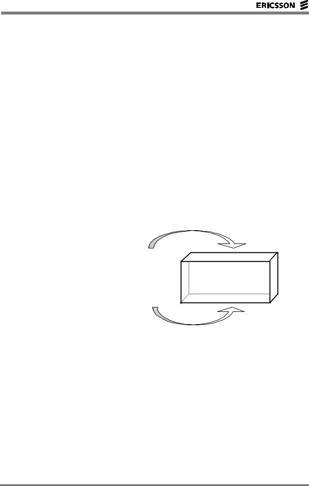
The main principle of GEM can be seen in the figure below.
Group Switch
Clocks (CLM) Interface to GDM ET155
Echo Cancellers Transcoders Regional Processors
GEM
Figure 4- 1 GEM is the basic building block in AXE 810
THE SUBRACK AND INTERFACES
Each GEM subrack is a generic piece of hardware which holds some mandatory boards but has 22 generic positions which can be used to house any type of board which is adapted to the GEM size and backplane. This creates a flexible solutions with many alternatives. The mandatory boards are:
•Two maintenance processors which take care of maintenance functions inside the subrack. The board is referred to as SCB-RP, Support and Connection Board with RP.
EN/LZT 123 6389 R1A |
– 1 – |
AXE 810 Delta
•Two group switch boards with a capacity of 16K ports of 64 kbit/s.
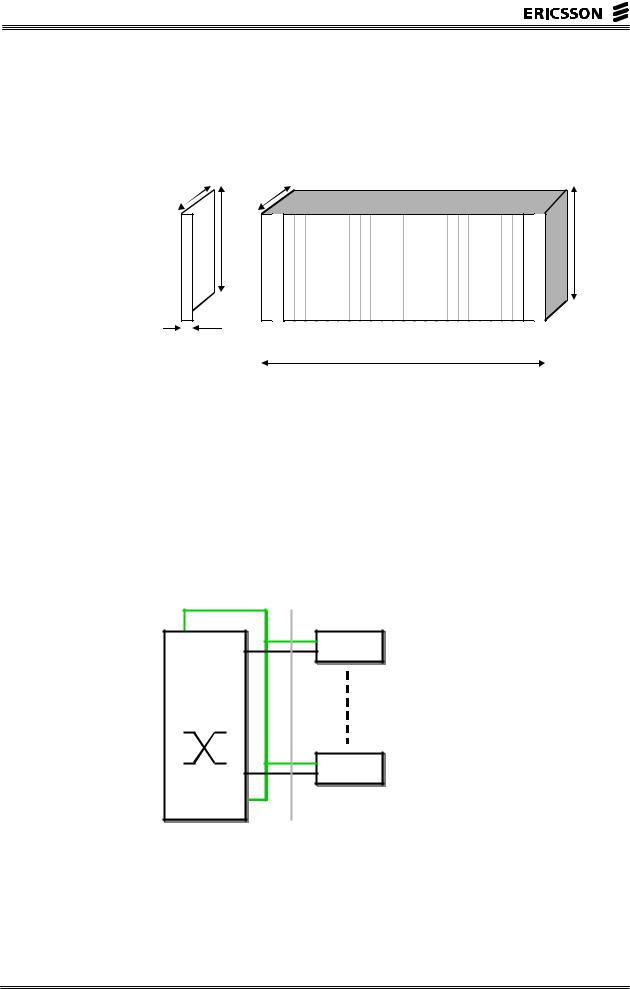
Beside these 4 boards, there are 22 positions that are free for usage. The figure below shows the main principle.
207.5 mm |
250 |
mm |
|
|
|
|
265 mm |
|
15 mm |
-RP |
GS |
|
||
|
SCB |
|
22 slots for free use
450 mm
300 mm
GS -RP
SCB
Figure 4- 2 The mandatory and free slots in GEM
The connection of devices to the group switch is done via the backplane. The interface is a new type of group switch interface with the name “DL34”. This interface is a flexible interface with a capacity of 128-2096 time slots of 64 kbit/s. The bit rate is 222.2 Mbit/s. This means that an ET155 board, which terminates up to 63 x 2.048 Mbit/s = 2016 time slots, can be connected via the DL34 interface. Devices with lower bit rate can of course also be connected as the number of channels is flexible. The figure below shows the main principle.
Device 1
Group
Switch
16k
Device 22
B
A
DL34
Figure 4- 3 Interfaces to the group switch inside the GEM subrack
The processing power for the device boards is supplied by the on-board integrated RPs that was mentioned in chapter 3. In the backplane of the GEM subrack, there are several busses. From a
– 2 – |
EN/LZT 123 6389 R1A |

4 Improvements Within APT
control point-of-view, the following two are the most interesting:
•a duplicated RP bus (serial RP bus)
•a 100 Mbit/s Ethernet for future use.
The figure below shows the control structure inside the subrack as well as the Ethernet connection which can be used by future applications. The boxes inside the boards represents the new regional processors which are integrated on the board, the RPI.
B
A  Device
Group
Switch
16k
Device
SCB-RP
A
SCB-RP  B
B
1 2
Figure 4- 4 The control structure inside GEM
The bus with number 1 is a duplicated serial RP bus in the backplane of the GEM subrack. The RP bus terminates in the RP Handler subrack of the Central Processor. The bus with number 2 in the figure is the duplicated 100 Mbit/s Ethernet bus which will be used by future applications. The SCB-RP has an Ethernet switch as well as one 1Gbit/s and one 100 Mbit/s Ethernet interface to the front of the board. It will be used by future functions in AXE.
CONNECTION OF GDM
AXE equipment inside the older GDM subracks (GDM stands for Generic Device Magazine) must in some way be able to coexist with the new GEM subracks. This is achieved by means of duplicated interface boards called DLEB inside the GEM subrack. These boards interface the DL3 interface from the GDM subrack. The DL3 interface is a 48Mbit/s (34 Mbit/s) interface which was used as the main interface to the old 128K
EN/LZT 123 6389 R1A |
– 3 – |

AXE 810 Delta
group switch in APT HWM 1.3 and 1.4. The figure below shows the main principles.
|
Device |
|
|
Group |
|
|
Device |
DLEB |
DLHB |
|
|
Switch |
|
||
16k |
DLEB |
DLHB |
|
|
|
||
|
|
GDM |
Device |
|
|
|
|
|
Device |
|
|
B
A |
GEM |
|
|
|
|
|
|
|
|
|
|
|
|
|
|
|
|
|
|
|
|
|
|
|
|
|
|
|
|
|
|
|
|
|
|
|
|
|
|
DL3 |
DL2 |
|
|
|
|
|
|
|
|
|
|
|
|
|
|
|
|
|
|
DL34 |
|
|
|
|
|
|
|
|
|
|
|
|
||||||||
|
|
|
|
|
|
|
|
|
|
|
|
|
|
|
|
|
|
|
|
|
|
|
|
|
|
|
|
|
(34 Mbit/s) |
(2 Mbit/s) |
||||||||
|
|
|
|
|
|
|
|
|
|
|
|
|
|
|
|
(222 Mbit/s) |
|
|
|
|
|
|
|
|
|
|
|
|||||||||||
|
|
|
|
|
|
|
|
|
|
|
|
|
|
|
|
|
|
|
|
|
|
|
|
|
|
|
|
|
|
|||||||||
Figure 4- 5 Connection of GDM subracks to GEM
DLEB stands for “Digital Link multiplexer for Existing equipment Board” and DLHB stands for Digital Link Handling Board. Each DLEB board can connect up to 4 DLHB boards (up to 4 GDM subracks) and there is always a need for two DLEB board; one for each plane in the group switch.
RESTRICTIONS
One important restriction when it comes to configuring the GEM subrack is that all positions in the subrack cannot house ET155 boards. The main reason is that 22 ET155 exceeds the switch capacity in the subrack which is 16k. One ET155 takes up to 2k so there can be up to 8 ET155 in the same subrack. A need for more ET155 boards is just spread out among several GEM subracks. Please note that these figures assumes fully used ET155. More ET155 may be located in the GEM subrack if not fully used.
– 4 – |
EN/LZT 123 6389 R1A |
4 Improvements Within APT
THE NEW GROUP SWITCH
GENERAL
The new group switch in AXE 810, which is referred to as GS890, is a completely new switch. In earlier AXE modernisations, the group switch structure has been the same but the hardware has been modified and extended to 128K. This time, the group switch is new. The main features are:
•Distributed architecture
The switch is located in every GEM subrack as indicated earlier in this book.
•Time-Space architecture
The old AXE group switch had a time-space-time (TST) architecture. This new one has a time-space (TS) architecture creating better characteristics.
•Maximum size of 512K
The switch can be scaled up to 512K multiple positions (64 kbit/s channels). This means that the switch can have more than 250 000 calls established at the same time (theoretically).
•Subrate switch up to 128K
The size of the subrate switch can be extended up to 128K. The subrate is used in mobile applications. The implementation of the subrate switch differs from earlier GS hardware.
•Strictly non-blocking
The old group switch in AXE was not strictly non-blocking as each inlet could be loaded to about 80%. The new architecture with time-space structure gives this advantage.
•Reduced cabling
The cabling has been reduced to about 1/12 if compared with the old switch (GS12).
•Reduced power consumption
The power consumption has been reduced to 1/6 of the old switch’s power consumption for the same switch size (GS12).
•Reduced space
The floor space is reduced significantly as a 16K subrack now is one circuit board. If compared with the old BYB 202 based switch, the changes are enormous as one 16K switch needed 32 TSM magazines occupying several cabinets.
EN/LZT 123 6389 R1A |
– 5 – |
AXE 810 Delta
•Device protection without waste of multiple positions For ET155, protection switching is an option. In that case, the interface to the group switch can connect two ET155:s without wasting multiple positions.
The architecture of the switch is further described in the following chapters.
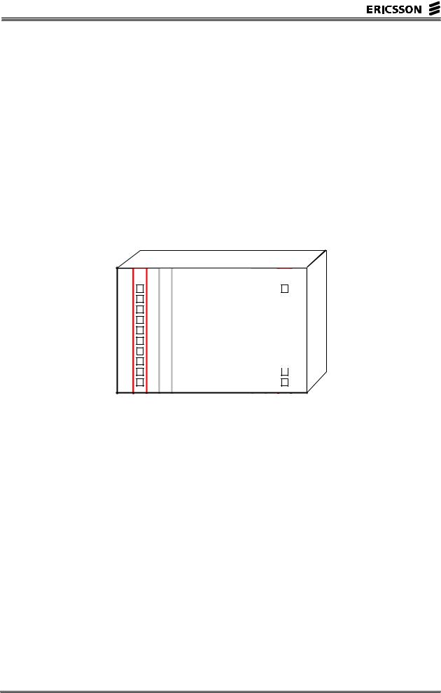
HARDWARE
The main hardware when it comes to switching is the XDB board (X means switching and DB stands for “distributed board”). The XDB boards has a switching capacity of 16K and there are two in each GEM subrack, one for the A-plane and one for the B-plane.
Maintenance Processor
XDB
16K A-plane
22 device slots


 Maintenance Processor
XDB
16K B-plane
Figure 4- 6 The XDB boards in GEM
On the XDB board, there are three ASICs (application specific integrated circuit) which implements the 16K switch. One ASIC is a multiplexer and two are holding the speech stores (SS) and control stores (CS). One integrated Regional Processor (RPI) is also on the XDB board. The devices in the subrack are connected to the XDB boards via the backplane while connection to other XDB boards are done via cables connected at the front of the board. The figure below shows the XDB board.
– 6 – |
EN/LZT 123 6389 R1A |

4 Improvements Within APT
DL5 |
DL34 |
(222 Mbit/s) |
|
(8K) |
(2K) |
Front
7 x Horizontals
3 x Verticals
128 x 32
MUX
Backplane
128 x 32
RPI
XDB
Figure 4- 7 Circuits on the XDB board
The structure of the switch is explained in next chapter.
STRUCTURE
If you only have a 16K group switch, it is enough to have just one XDB circuit board. However, in case of larger switches, the XDB boards have to be inter-connected by means of so-called horizontal and vertical connections. The horizontal and vertical connections are best explained if you imagine all XDB boards put in a matrix. The figure below shows the main idea.
|
0-0 |
|
0-1 |
|
0-2 |
|
0-3 |
|
0-4 |
|
0-5 |
|
0-6 |
|
0-7 |
|
|
|
|
|
|
|
|
|
|
|
|
|
|
|
|
|
|
|
|
|
|
|
|
|
|
|
|
|
|
|
|
|
1-0 |
|
1-1 |
|
1-2 |
|
1-3 |
|
1-4 |
|
1-5 |
|
1-6 |
|
1-7 |
|
|
|
|
|
|
|
|
|
|
|
|
|
|
|
|
|
|
|
|
|
|
|
|
|
|
|
|
|
|
|
|
|
2-0 |
|
2-1 |
|
2-2 |
|
2-3 |
|
2-4 |
|
2-5 |
|
2-6 |
|
2-7 |
|
|
|
|
|
|
|
|
|
|
|
|
|
|
|
|
|
|
|
|
|
|
|
|
|
|
|
|
|
|
|
|
|
3-0 |
|
3-1 |
|
3-2 |
|
3-3 |
|
3-4 |
|
3-5 |
|
3-6 |
|
3-7 |
|
|
|
|
|
|
|
|
|
|
|
|
|
|
|
|
|
|
|
|
|
|
|
|
|
|
|
|
|
|
|
|
Figure 4- 8 A matrix of switch boards.
Each board has a capacity of 16K so the maximum capacity in the switch is 4 rows x 8 columns x 16K = 32 x 16 = 512K.
Horizontals and Verticals
The inter-connection of the boards in the switch is done by two different types of connections:
EN/LZT 123 6389 R1A |
– 7 – |
Loading...