


AXE 810—The evolution continues
Magnus Enderin, David LeCorney, Mikael Lindberg and Tomas Lundqvist
Thanks primarily to an architecture that was developed to support change, the AXE exchange continues to evolve. Its architecture and modularity have benefited customers—AXE has served as local exchanges and international exchanges, and even in mobile networks to provide mobile switching centers (MSC), home location registers (HLR), and other functions. This has resulted in a total number of about 13,000 exchanges and an all-time-high growth rate.
The modularity of AXE makes it possible to add new functionality in a cost-effective way, but hardware and software R&D must also make the most of new technologies.
This article describes recent adaptations of hardware and software that will prepare AXE for the next generation of networks. The authors focus on a system architecture that will serve as the basis for migration toward a server-gateway architecture for third-generation mobile networks and the next generation of multiservice networks. Adaptations will also enable improvements in existing networks where traffic is growing quickly.
Introduction
In the next few years, networks will evolve toward today’s vision of an “all-IP” network. We can see two possible scenarios: one for traditional networks, and one for “nextgeneration” networks. For traditional networks, the scenario describes what will happen in multiservice networks and in second-
generation mobile networks, such as GSM. The next-generation network scenario describes the development of mobile Internet and fast Internet access in fixed networks.
In traditional networks, evolution is driven by never-ending growth in the need for processing capacity; in mobile networks, by growth in the number of subscribers and usage levels per subscriber. The wireline network is also experiencing a sharp increase in traffic because of Internet “surfing.”
In next-generation networks, traditional telephone and data networks will converge to become general networks designed for many different services and modes of access. The convergence of data and telecommunications makes it possible to combine the best of two worlds. Some requirements, such as the need for heightened performance, are fulfilled more easily when development is based on data communications products. Also, the variety of access modes—via secondand third-generation mobile networks, the multiservice networks, and broadband—will necessitate the coexistence of different transmission formats. Thus, gateways will be required at network interconnection points.1
BOX A, TERMS AND ABBREVIATIONS
AAL |
ATM adaptation layer |
GCP |
Gateway control protocol |
RAID |
Redundant array of independent |
ACS |
Adjunct computer subsystem |
GDDM |
Generic datacom device magazine |
|
disks |
ALI |
ATM link interface |
|
(subrack) |
RAM |
Random access memory |
AM |
Application module |
GDM |
Generic device magazine (subrack) |
RISC |
Reduced instruction set computer |
AP |
Adjunct processor |
GEM |
Generic Ericsson magazine (subrack) |
RLSES |
Resource layer service specification |
APC |
AM protocol carrier |
GS |
Group switch |
RM |
Resource module |
APIO |
AXE central processor IO |
GSM |
Global system for mobile |
RMP |
Resource module platform |
APSI |
Application program service |
|
communication |
RP |
Regional processor |
|
interface |
GSS |
Group switch subsystem |
RPC |
Remote procedure call |
ASIC |
Application-specific integrated |
HDLC |
High-level data-link control |
RPP |
Regional processor with PCI interface |
|
circuit |
HSB |
Hot standby |
SCB-RP |
Support and connection board - RP |
ATM |
Asynchronous transfer mode |
IO |
Input-output |
SDH |
Synchronous digital hierarchy |
BICC |
Bearer-independent call control |
IOG |
Input-output group |
SES |
Service specification |
BIST |
Built-in self-test |
IP |
Internet protocol |
SONET |
Synchronous optical network |
BSC |
Base station controller |
IPN |
Interplatform network |
SS7 |
Signaling system no. 7 |
C7 |
CCITT (now ITU-T) no. 7, a com- |
ISDN |
Integrated services digital network |
STM |
Synchronous transfer mode |
|
mon-channel signaling system |
ISP |
Internet service provider |
STOC |
Signaling terminal open communi- |
CAS |
Channel-associated signaling |
IWU |
Interworking unit |
|
cation |
CP |
Central processor |
MGW |
Media gateway |
TCP |
Transmission control protocol |
cPCI |
Compact peripheral component |
MIPS |
Million instructions per second |
TDMA |
Time-division multiple access |
|
interconnect |
MSC |
Mobile switching center |
TRA |
Transcoder |
CPP |
Cello packet platform |
MSCS |
Microsoft cluster server |
TRC |
Transceiver controller |
DL |
Digital link |
MSP |
Multiplex section protection |
TSP |
The server platform |
DLEB |
Digital link multiplexer board in the |
MTP |
Message transfer part |
TU 11, 12 |
Typical urban 11 (12) km/hr |
|
GEM |
MUP |
Multiple position (timeslot) |
UMTS |
Universal mobile telecommunica- |
DSA |
Dynamic size alteration |
NGS |
Next-generation switch |
|
tions system |
DTI |
Data tranmission interworking |
OSS |
Operations support system |
VCI |
Virtual channel identifier |
ECP |
Echo canceller in pool |
PCM |
Pulse code modulation |
VPI |
Virtual path identifier |
ET |
Exchange terminal |
PDH |
Plesiochronous digital hierarchy |
XDB |
Switch distributed board |
ETSI |
European Telecommunications |
PLMN |
Public land mobile network |
XSS |
Existing source system |
|
Standards Institute |
PSTN |
Public switched telephone network |
WCDMA |
Wideband code-division multiple |
FTP |
File transfer protocol |
PVC |
Permanent virtual circuit |
|
access |
10 |
Ericsson Review No. 1, 2001 |
Typical of next-generation network architecture is the separation of connectivity and communication or control services. This new new architecture will appear first in GSM and WCDMA/UMTS core networks, where AXE exchanges will continue to serve as MSCs. For multiservice networks, telephony servers will become hybrid nodes which consist of an AXE exchange that uses an AXD 301 to handle packet-switched data.
Based on the traditional and nextgeneration scenarios, network evolution will demand increased processing capacity, greater switching capacity, and conversion to packet-switched technology. In addition, new ways of doing business will emerge as virtual operators pay for the right to use telecom equipment owned by other operators. Similarly, more operators are expected to enter the market, putting additional demands on charging and accounting functions.
To succeed in today’s telecommunications market, operators must be able to provide their users with new functionality in networks and complete coverage by mobile systems at the same or a lower cost as time progresses. Operators put demands on the return on investment, cost of ownership, footprint (multiple nodes per site), plug- and-play functionality (short lead times in the field), and quality of software packages (quality of service).
This article describes the latest developments made in the AXE platform to meet these requirements, and what new products will be launched. For example, to shorten the software development cycle, a layered architecture was introduced in the early 1990s, resulting in application modules (AM). Current work on application modules focuses on the server-gateway split. AXE hardware is also undergoing a major architectural transformation to further reduce the footprint, power consumption, and number of board types.
Ericsson’s goal is to cut the time to customer for AXE by targeting improvements in production, transportation, and installation. Far-reaching rationalization has been achieved through the introduction of the generic Ericsson magazine (GEM), an open, flexible, scalable, high-capacity magazine (subrack). A new distributed, non-blocking group switch (GS890) has also been introduced, as have new devices, such as the ATM link interface (ALI) and ET155-1, which enable AXE to serve as a gateway to an ATM
network. Also, a new input-output (IO) system, called the APG40, has been developed using products from mainstream data communications vendors.
The application platform
The traffic-handling part of AXE has a twolayer architecture: the application platform, which consists of hardware and software; and the traffic applications, which solely consist of software. The application platform can be seen in terms of hardware and software, which present different but complementary views of the architecture.
The software view
The AXE application software has continued to evolve since it was first layered and modularized in the early 1990s. Market demand for shorter lead-times was the main force driving the change to layers and modularization.
Application modules
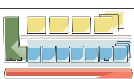
Traffic applications are encapsulated in application modules that use the applicationplatform software—called the resource module platform (RMP). There is no direct communication between application modules. All communication between them takes place via protocols, where the protocol carriers are implemented in the resource module platform (Figure 1).
Figure 1
AXE 810 application software architecture.
AM |
AM |
AM |
AM |
XSS
APSI
CON |
COM |
OM |
CHA |
NAP |
C7 |
Other |
RM |
RM |
RM |
RM |
RM |
RM |
RMs |
|
|
|
|
|
|
RMP |
|
|
APZ |
|
|
|
|
Ericsson Review No. 1, 2001 |
11 |

|
|
GEM |
|
|
|
GDM |
|
Ethernet |
|
|
DL2 |
EMBUS |
|
|
|
RPB-S |
|
|
RPB-S |
|
|
|
|
|
|
||
|
|
|
|
|
|
PDH |
|
|
|
|
|
|
ETC5 |
|
|
DL34 |
|
|
|
PDH |
|
|
|
DL3 |
|
ETC-T1 |
|
SONET |
ET155 |
|
|
PDH |
||
|
|
|
|
|||
|
|
|
|
|
ETC-J32 |
|
SDH |
ET155 |
|
|
|
|
RPP |
|
|
|
|
DLHB |
||
|
TRA |
|
|
|
RPG3 |
|
|
|
|
|
|
||
|
ECP |
XDB |
|
DLEB |
|
PDSPL2 |
|
|
|
|
|
||
|
IRB |
DL34 |
|
|
|
M-AST |
External |
|
|
|
|
|
|
IRB |
|
|
|
|
S7V35 |
|
sync |
|
|
|
|
||
ETC |
LRB |
|
|
|
|
S7DS0A |
sync |
|
|
|
|
||
|
|
|
|
|
|
J7X21-2 |
|
CGB |
|
|
|
|
DL2 (cable) |
|
|
|
|
|
DL2IO |
|
|
CGB |
|
|
|
|
SDH |
|
Ethernet |
RPB-S |
|
ALI |
||
|
|
|
|
|||
|
SCB-RP |
SCB-RP |
|
RP4 |
||
|
|
|
|
|
|
RPB-S |
|
|
|
|
|
|
RPB-S |
|
|
|
|
|
|
Ethernet (IPN) |
|
|
|
|
|
|
Ethernet (IPN) |
|
|
Remote Ethernet (TCP/IP) |
APG |
VGA display |
||
|
|
Local Ethernet (TCP/IP) |
External alarm |
|||
|
|
|
||||
|
RPHS |
RPHS |
|
Keyboard |
|
Alarm panel |
|
|
|
|
|
||
|
CP |
|
|
|
HD |
|
|
|
|
|
|
|
|
Figure 2 |
|
|
|
|
|
|
Hardware architectural overview. |
|
|
|
|
||
BOX B, CURRENT RESOURCE MODULES
•Connection RM (CONRM)
•Communication RM (COMRM)
•Operation and maintenance RM (OMRM)
•Network access products RM (NAPRM)
•Pooled devices RM (PDRM)
•Common channel signaling RM (C7RM)
•Charging support RM (CHARM)
The interface of the resource module platform with the application modules, called the application platform service interface (APSI), is a formalized client-server interface. Subsets of the APSI, or individual interfaces, are called service specifications (SES). Each service specification provides a service for the application modules, some of the most important services being:
•connection service—for setting up a physical connection;
•communication service—for communication between application modules;
•object manager—for operation and maintenance;
•AM protocol carrier (APC);
•charging service; and
•services for signaling no. 7 (SS7), such as the message transfer part service.
The total concept, which consists of the
RMP, APSI, the AMs, and the inter-AM protocols, is known as the application modularity concept. It is largely thanks to this concept that the system lifetime of AXE consistently exceeds expectations—the AXE system is 30 years old, yet we see no end to its potential evolution.
Resource modules
When the RMP was first introduced, it was small in comparison to the large volume of existing software, called existing source system (XSS). Following several RMP development projects, the migration from the earlier architecture to the AM architecture is now virtually complete. The resource module platform, in turn, has become large and complex, leading to a refinement of the AM concept and the division of the RMP into several resource modules (RM). The interfaces provided by the resource modules are formalized as resource-layer service specifications (RLSES).
A priority in the development of RMs and AMs (known collectively as system modules) is to specify the interfaces (SES and RLSES) early in the development process. When the interfaces are “frozen”, the separate system modules can be designed independently of one another, often at different geographical locations, as is common in the Ericsson organization.
The second major advantage for development of applications is that applicationplatform hardware is now associated with specific resource modules and controlled by them. Application modules simply request services via the APSI. Hardware is “owned” by the software in the respective resource modules.
Hardware
The hardware (Figure 2) revolves around the GS890 group switch, which has 512 K multiple positions, each with a bit rate of 64 kbit/s.
The biggest change in the hardware architecture is the addition of a new exchange interface (the DL34) to existing DL3 and DL2 interfaces. The DL34 interface supports from 128 to 2,688 timeslots to each device board, in steps of 128, via a backplane interface in the generic Ericsson magazine running at 222 Mbit/s. This interface made it possible to improve the devices connected to the group switch, further reducing input power, cabling, the number of board types, footprints, installation time, and other parameters. The high-speed DL34 in-
12 |
Ericsson Review No. 1, 2001 |
terface has also facilitated a more efficient version of the group switch itself, also located in the GEM.
Another architectural change (Figure 2) is the interplatform network (IPN). In the first phase, the IPN will be used to speed up communication between the central processor (CP) and adjunct processors (AP). The interface is based on fast Ethernet. In a second phase, it will be upgraded to Gigabit speed.
All devices that support the DL34 interface can be mixed in the GEM more or less without limit. The maximum capacity of each GEM is 16 K multiple-position timeslots (MUP), which corresponds to eight
STM-1 ET boards, for example. Physically, there is space for 22 device boards in one GEM.
If a switch is needed that is larger than 16 K MUPs, or when the number of devices exceeds 22, additional GEMs must be added. These can be configured without interruption while the system is processing traffic. An exchange based on the GEM is linearly expandable. The maximum switch size is 512 K MUPs at normal rate (64 kbit/s) or 128 K MUPs at a subordinate rate (n x 8 kbit/s).
By inserting a pair of digital link multiplexer boards (DLEB) in the GEM, we can convert the DL34 backplane interface into four DL3 cable interfaces. This allows all of today’s devices in the generic device magazine (GDM), generic datacom device magazine (GDDM), and other formats to be used with the new switch core.
Software evolution
The original AXE concept has enabled ongoing evolution and modernization. Legacy software can be reused or modified, subsystems and system modules can be modernized or completely replaced, interfaces can be left unchanged or redesigned to meet new needs, and new architectures can be introduced. Yet AXE remains fundamentally AXE.
Several software development programs are under way in parallel. The APZ processor is being adapted to serve as a multiprocessor CP to multiply call-handling capacity. Cost of ownership is being reduced. Ericsson is improving its internal management of software to reduce time-to-market and time-to-customer. These activities are in addition to the four programs described below.
1999 |
|
|
|
|
|
2001 |
|
|
|
|
|
2001/2002 |
|
|
|
|||||||||||
|
|
AM |
|
AM |
AM |
|
|
|
AM |
AM |
|
|
AM |
|||||||||||||
|
|
|
|
|
|
|
|
|||||||||||||||||||
XSS |
|
|
|
|
|
|
|
|
|
|
|
|
|
SS7 |
|
|
|
|
|
|
|
SS7 |
||||
|
|
|
|
|
|
|
|
|
|
|
|
|
|
|
|
|
|
|
|
|||||||
|
|
|
|
|
|
|
|
|
|
|
|
|
|
|
|
|
|
|
|
|
|
|
||||
|
|
|
|
|
|
|
|
|
|
|
|
|
|
|
|
|
|
|
|
|
|
|
|
|
|
|
|
|
|
|
|
RMP |
|
|
|
Server module |
Server module GCP |
||||||||||||||||
|
|
|
|
|
|
|
|
|
|
|
|
|
|
|
|
|
|
|
|
|
|
|
|
|
|
|
|
|
SS7 |
|
|
|
STM |
|
|
|
|
|
|
|
|
|
|
|
|
|
|
|
|
GCP |
|
||
|
|
|
|
|
|
|
|
|
|
|
|
|||||||||||||||
|
|
|
|
|
|
|
|
|
|
|
|
|
|
|||||||||||||
|
|
|
|
|
|
|
|
|
Gateway module |
Media gateway |
||||||||||||||||
|
|
|
|
|
|
|
|
|
|
|
|
|
|
STM |
|
|
|
AAL2/AAL5 |
||||||||
|
|
|
|
|
|
|
|
|
STM |
|
|
|
AAL2/AAL5 |
|
|
|
||||||||||
|
|
|
|
|
|
|
|
|
|
|
|
|
||||||||||||||
Figure 3
Software evolution toward the server-gateway split.
Software migration
The network architecture is changing. In particular, we see two new types of node: the server (or media-gateway controller) and the media gateway itself, resulting in what is known as the “server-gateway split.” In order to meet the demands of the new architecture, the software in the application platform is being migrated from a traditional telecom environment—which is STM-based, mainly for voice traffic—to-
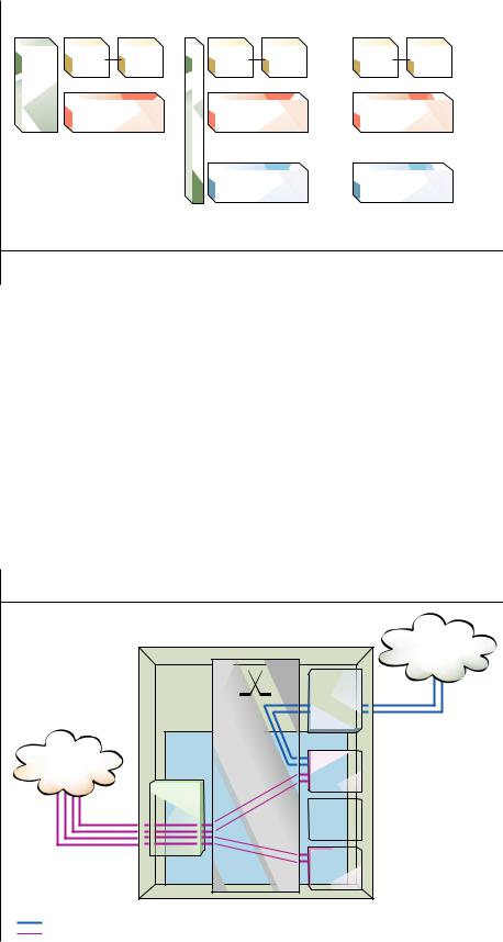
Figure 4 |
|
|
System architecture, ATM interworking function. |
|
|
|
AXE media gateway |
STM network |
|
|
|
|
|
ET |
ATM/AAL2 |
GSS |
TRA |
network |
|
|
|
or DTI |
|
|
|
|
|
ALI |
|
|
|
TRA |
|
|
or DTI |
Switched 64 kbit/s connections for PCM coded voice |
|
|
Switched 64 kbit/s connections for HDLC framed voice or data packets |
||
Ericsson Review No. 1, 2001 |
13 |

System downtime |
|
|
|
|
|
|
ward a packet-based environment, initially |
||||||
|
|
|
|
|
|
|
|
|
for ATM, and subsequently for IP. |
|
|||
|
|
|
|
|
|
|
|
|
In this new architecture, the server con- |
||||
|
|
|
|
|
|
|
|
|
|||||
|
|
|
|
|
|
|
|
|
trols the call or session, whereas the media |
||||
|
|
|
|
|
|
|
|
|
|||||
|
|
|
|
|
|
|
|
|
gateway provides the bearer service, trans- |
||||
|
|
|
|
|
|
|
|
|
|||||
|
|
|
|
|
|
|
|
|
|||||
|
|
|
|
|
|
|
|
|
mitting information over the connectivity |
||||
|
|
|
|
|
|
|
|
|
|||||
|
|
|
|
|
|
|
|
|
layer. An advantage of separating call con- |
||||
|
|
|
|
|
|
|
|
|
|||||
|
|
|
|
|
|
|
|
|
trol from bearer control is that bearer tech- |
||||
|
|
|
|
|
|
|
|
|
|||||
|
|
|
|
|
|
|
|
|
nology can be upgraded from STM via ATM |
||||
|
|
|
|
|
|
|
|
|
|||||
|
|
|
|
|
|
|
|
|
to IP without affecting the call control. |
|
|||
|
|
|
|
|
|
|
|
|
|
||||
|
|
|
|
|
|
|
|
|
The original AM architecture has proved |
||||
1999 |
2000 |
2001 |
2002 |
||||||||||
itself to be future-proof and is well suited to |
|||||||||||||
|
|
|
|
|
|
|
|
|
|||||
|
|
Complete exchange failure |
|
|
accommodate the server-gateway split. The |
||||||||
|
|
|
|
||||||||||
|
|
Software upgrade |
|
|
|
|
split has been implemented in system mod- |
||||||
|
|
Restart with reload |
|
|
|
|
|||||||
|
|
|
|
|
|
ules (new and modified AMs and RMs) |
|||||||
|
|
Large restart |
|
|
|
|
|||||||
|
|
|
|
|
|
||||||||
|
|
Small restart |
|
|
|
|
without any fundamental changes to the |
||||||
|
|
|
|
|
|
||||||||
|
|
|
|
|
|
|
|
|
software architecture. For example, new |
||||
Figure 5 |
|
|
|
|
|
|
RMs for bearer-access service and for TDM |
||||||
|
|
|
|
|
|
access are currently being developed for the |
|||||||
Reduction in system downtime. |
|
|
|||||||||||
|
|
|
|
|
|
|
|
|
WCDMA/UMTS program. |
|
|
||
|
|
|
|
|
|
|
|
|
Two separate migration tracks are |
||||
|
|
|
|
|
|
|
|
|
currently |
being followed. |
For |
the |
|
|
|
|
|
|
|
|
|
|
WCDMA/UMTS program, AXE is the nat- |
||||
|
|
|
|
|
|
|
|
|
ural choice of technology for the server, |
||||
|
|
|
|
|
|
|
|
|
thanks to its high capacity and high level of |
||||
|
|
|
|
|
|
|
|
|
functionality. AXE is also available as a com- |
||||
|
|
|
|
|
|
|
|
|
bined server/media-gateway node, where the |
||||
|
|
|
|
|
|
|
|
|
server part controls its own gateway part. By |
||||
|
|
|
|
|
|
|
|
|
contrast, the Cello packet platform (CPP) is |
||||
|
|
|
|
|
|
|
|
|
the preferred choice of technology for ATM- |
||||
|
|
|
|
|
|
|
|
|
based media gateways. In such a network, |
||||
|
|
|
|
|
|
|
|
|
the server nodes communicate using bearer- |
||||
|
|
|
|
|
|
|
|
|
independent call control (BICC). The server |
||||
|
|
|
|
|
|
|
|
|
controls the gateway using the gateway con- |
||||
|
|
|
|
|
|
|
|
|
trol protocol (GCP). ATM-based gateways |
||||
|
|
|
|
|
|
|
|
|
communicate using Q.AAL2. |
|
|
||
|
|
|
|
|
|
|
|
|
The second migration track is for the next- |
||||
|
|
|
|
|
|
|
|
|
generation switch (NGS) program for the |
||||
|
|
|
|
|
|
|
|
|
multiservice network. The server node is a |
||||
|
|
|
|
|
|
|
|
|
hybrid node made up of co-located AXE and |
||||
|
|
|
|
|
|
|
|
|
AXD 301 systems. The gateway node con- |
||||
|
|
|
|
|
|
|
|
|
sists of |
an ATM switch |
(also |
an |
|
|
|
|
|
|
|
|
|
|
AXD 301) for AAL1 connections, and is |
||||
|
|
|
|
|
|
|
|
|
controlled by the server using the gateway |
||||
|
|
|
|
|
|
|
|
|
control protocol. |
|
|
||
In-service performance
Robustness, or in-service performance, has long been a priority in AXE development, and considerable improvements have been and are still being made. No software is 100% reliable, but robust systems can be achieved by means of recovery mechanisms that minimize the effects of software malfunctions or program exceptions.
One of the most powerful robustness mechanisms is known as forlopp, which is a recovery mechanism at the transaction level. (Forlopp is an anglicization of the Swedish
word förlopp, roughly the “sequence of events.”) The forlopp mechanism is a lowlevel recovery mechanism by which only the transaction affected by the software malfunction is released. This minimizes the disturbance to the overall system. The forlopp mechanism, which has been refined in several stages and is now applied to all traffic handling in AXE and to many operation and maintenance functions, has significantly reduced the number of recoveries at the system level.
System restart is used as a recovery mechanism for certain faults and for system upgrades. The restart mechanism itself has been optimized in several ways, so that in the few cases that still require restart, its duration is as short as possible.
Activities for restarting software in the regional processor (RP) have been especially improved. For example, regional processors are restarted through minimal restart by de- fault—that is, with the suppression of unnecessary actions. Complete restarts are performed on regional processors only when necessary. Regional processors are restarted asynchronously, which means that no regional processor has to wait for any other regional processor to become ready for a restart phase. These improvements have significantly reduced the time consumed when restarting application hardware.
If necessary, AXE can, via the IPN, be reloaded from the backup copy of the system on the APG40 file system. This approach is ten times faster than the design that applied before the APG40 and IPN were introduced. Also, the time it takes to make a backup copy of the system on APG40 is onefifth of what it was before.
The restart duration for a system that is upgrading to new software has also been reduced. The most recent improvements involve RP software, which is now preloaded prior to an upgrade, instead of during the upgrade, thus saving restart time.
Major improvements have been made to the function-change mechanism used for system upgrades. Inside the central processor, the time needed for data transfer prior to a changeover to new software has been cut from hours to typically ten minutes. (The data transfer does not disturb traffic handling, but exchange data cannot be changed during data transfer.)
Another improvement applies to the retrofit of new CPs that replace old ones. The bandwidth of the connection between the processors has been expanded by using re-
14 |
Ericsson Review No. 1, 2001 |
 Loading...