


LBI-38389B
Mobile Communications
TMX™ — 8825 (25W) TMX™ — 8810 (10 W)
Installation Manual
|
|
TABLE OF CONTENTS |
|
|
Page |
INTRODUCTION . . . . . . . . . . . . . . . . . . . . . . . |
3 |
UNPACKING AND CHECKING EQUIPMENT . . . . . . . |
3 |
STANDARD EQUIPMENT . . . . . . . . . . . . . . . . . . |
3 |
OPTIONS . . . . . . . . . . . . . . . . . . . . . . . . . . . . |
3 |
PLANNING THE INSTALLATION . . . . . . . . . . . . . . |
6 |
EQUIPMENT REQUIRED . . . . . . . . . . . . . . . . . . . |
6 |
INSTALLATION IN VEHICLES POWERED |
|
BY LIQUEFIED (LP) GAS . . . . . . . . . . . . . . . . . . . |
7 |
RUNNING CABLES . . . . . . . . . . . . . . . . . . . . . . |
8 |
POWER AND IGNITION CABLES . . . . . . . . . . . |
8 |
INSTALLING THE RADIO . . . . . . . . . . . . . . . . . . |
11 |
MICROPHONE CONNECTIONS . . . . . . . . . . . . . . . |
12 |
MICROPHONE BRACKET . . . . . . . . . . . . . . . . . . |
12 |
ANTENNA . . . . . . . . . . . . . . . . . . . . . . . . . . . |
13 |
OPTIONAL ACCESSORIES . . . . . . . . . . . . . . . . . . |
15 |
AC POWER SUPPLY (12 VOLTS AT 13 AMPS) . . . . |
15 |
DESK MICROPHONE OPTION MC1M (MC03) |
|
(19B851086P10) . . . . . . . . . . . . . . . . . . . . . . |
15 |
OPTION CABLE OPTION CC3N (CC08) |
|
(19C85158P3) . . . . . . . . . . . . . . . . . . . . . . . |
16 |
UNIVERSAL TONE CABLE OPTION CC3P (CC09) |
|
(19C851585P5) . . . . . . . . . . . . . . . . . . . . . . |
17 |
EXTERNAL SPEAKER OPTION LS1E (LS01) |
|
(19C850550) . . . . . . . . . . . . . . . . . . . . . . . . |
17 |
EXTERNAL ALARM (HORN) RELAY OPTION SU1C |
|
(SUO1) (19A705499P1) . . . . . . . . . . . . . . . . . . |
18 |
EXTERNAL ALARM ON/OFF SWITCH |
|
OPTION SU1F (SU02) (19C851585P7) . . . . . . . . . |
19 |
INTERCONNECTION DIAGRAM . . . . . . . . . . . . . . |
21 |
OPTION INTERCONNECTION DIAGRAM . . . . . . . . . |
22 |
|
|
This manual is published by Ericsson GE Mobile Communications Inc., without any warranty. Improvements and changes to this manual necessitated by typographical errors, inaccuracies of current information, or improvements to programs and/or equipment, may be made by Ericsson GE Mobile Communications Inc., at any time and without notice. Such changes will be incorportated into new editions of this manual. No part of this manual may be reproduced or transmitted in any form or by any means, electronic or mechanical, including photocopying and recording, for any purpose, without the express written permission of Ericsson GE Mobile
Communications Inc.
Copyright© October 1989, General Electric Company
2

INTRODUCTION
This manual contains installation instructions for the TMX-8825 and TMX-8810 Mobile Radios and associated accessories. Included are mounting instructions, for connecting the ignition cable assemblies and suggested cable routings. Interconnection and wiring diagrams are contained in the back of this manual.
UNPACKING AND CHECKING EQUIPMENT
Carefully unpack the Two-Way Radio. It is recommended that you identify the items ordered and check them off in the box below before discarding the packing material. If any damage has occurred to the equipment during shipment, file a claim with the carrier immediately.
STANDARD EQUIPMENT
Two-Way Radio
Microphone 19B801398P4
Microphone Hanger 19B801398P5
Battery Power Cable 19B801358P2
Mounting Hardware Kit 19A138051G11
OPTIONS
Option PD1A (PD01) - Noise Suppression Kit 19A148539G1
Option PS1C (PS03) - AC Power Supply 121 Volt, 60 Hz, 13 Amp19A704647P2
Option PS1D (PS04) - AC Power Supply 121/242 Volt, 50/60 Hz, 13Amp 19A704647P3
Option MC1M (MC05) - Desk Microphone 19B851086P10
Option CC3N (CC08) - Option Cable 19C851585P3
Option CC3P (CC09) - Universal Tone Cable (requires Option
CC08) 19C851585P5
Option CC3R (CC10) - Power Cable (20 foot) 19B801358P4
3

Option LS1E (LS01) - External Speaker (Dash Mount)
19C850550G6
(requires Option CC08)
Option SU1C (SU01) - External Alarm (Horn) Relay 19A705499P1 (requires Option CC08) and SU02)
Option SU1F (SU02) - External Alarm ON/OFF Switch
19C851585P7
(requires Option SU01)
Option MA1L (MA03) - Desk Radio Mounting Wedge 19C851685G2
NOTE
The original option numbers for the TMX-8825 and TMX-8810 options have been replaced with new option numbers. both the old and new option numbers are shown for clarity. The new option number is shown first, and the old option number is shown in parentheses. For example:
External Speaker Option LS1E (LS01)--where Option LS1E is the new option number, and (LS01) is the old option number.
4
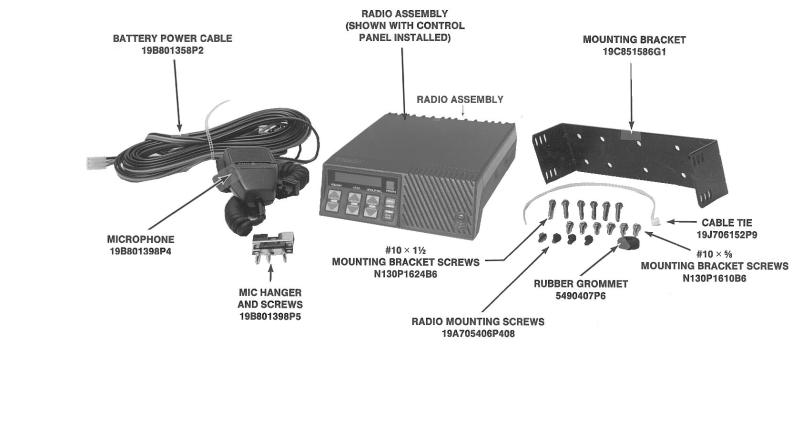
Figure 1 - Radio Components and Mounting Hardware
5

WARNING
Interference with Vehicular Electronics - Electronic fuel injection systems, electronic anti-skid braking systems, electronic cruise control systems, etc., are typical of the types of electronic devices which may be prone to malfunction due to the lack of protection from radio frequency energy present when transmitting. If the vehicle contains such equipment, consult the dealer for the make of the vehicle and enlist his aid in determining if such electronic circuits will perform normally when the radio is transmitting.
The accompanying illustrations should help you in your installation.
PLANNING THE INSTALLATION
Before starting, plan your installation carefully so that it will be:
∙Safe for the operator and passengers in the vehicle.
∙Safe to operate within easy reach of controls and microphone.
∙Protected from damage from water.
∙Easy for the serviceman to service.
∙Oriented to minimize refections in LCD display.
∙Neat
∙Out of the way of auto mechanics.
EQUIPMENT REQUIRED
The equipment required for installing the radio is:
∙Electric Drill
∙No. 31 (1/8-inch) drill for No. 8 screws
∙No. 27 (9/64-inch) drill for No. 10 screws
∙Phillips screwdriver
∙Crimp tool for terminals and antenna connector.
∙No. 20 TORX® driver or 1/4-inch HEX driver for mounting radio
∙5/8-inch punch or hole saw for rubber grommet
It is suggested that you take advantage of the experience of one of the many authorized General Electric Service Stations located throughout the United States by having them install the equipment.
TORX® Trademark of CAMCAR Division, TEXTRON, Inc.
6

CAUTION
Be careful to avoid damaging some vital part (fuel tank, transmission housing, etc.) of the vehicle when drilling mounting holes. Always check to see how far the mounting screws will extend below the mounting surface before installing.
Figure 2 - Typical Hump or Dash Mount
INSTALLATION IN VEHICLES POWERED BY LIQUEFIED (LP) GAS
WARNING
Radio installations in vehicles powered by liquefied petroleum gas must conform to the following requirements.
Radio installations in vehicles powered by liquefied petroleum gas with the LP-gas container in the trunk or other sealed-off space within the interior of the vehicle must conform to the National Fire Protection Association Standard NFPA 58 which requires that:
∙Space containing radio equipment shall be isolated by a seal from the space containing the LP-gas container and its fitting.
∙Outside filling connections shall be used for the LP-gas container.
∙The LP-gas container space shall be vented to the outside of the vehicle.
7

RUNNING CABLES
To assure feasibility of the cable routing you plan to use, it is suggested that you run the cables before mounting the equipment. Be sure to leave some slack in the cables going to the equipment so that the equipment may be pulled out for servicing with the power applied and antenna attached.
Try to route the cables away from locations where they will be exposed to heat (exhaust pipes, mufflers, tailpipes, etc.), battery acids, sharp edges or mechanical damage, or where they will be a nuisance to automobile mechanics, the driver or passengers. Keep wiring away from electronic computer modules, other electronic modules and ignition circuits to help prevent interference to these components and radio equipment.
In addition, try to utilize existing holes in the firewall and trunkwall and the channels above and beneath the doors. You may also use the channel through door and window columns, where they are convenient for running cables, unless you plan to install rigid or flexible conduit in which to run the cables.
POWER AND IGNITION CABLES
The Power Cable consists of a red lead, an orange lead, a black lead, a 3 pin systems plug, and a set of fuses and fuse holders to be installed (See Figure 3).
To install the Power Cable, start with the plug end of the cable at the location of the radio and run the three leads to the firewall, drill a 5/8 inch hole and insert a rubber grommet (customer supplied).
To install the fuses: 1)Cut off 12 to 18 inches from the red and orange wires; 2) Strip back the insulation approximately 3/8 of an inch on each end of the wires; 3) Insert the stripped end of each wire into the small opening at the end of each fuse holder section and crimp the wire to the fuse holder section; and 4) Place the fuse into the large section of the fuse holder and snap the large end of the fuse holder to the small end of the fuse holder.
Connect the orange fused lead to the positive (+) battery terminal, and the black to the negative (-) battery terminal. Always locate the fuse as close to the battery as possible.
Connect the red lead to the ignition "on" sense point (preferably an "Accessory" point on the fuse panel that is switched on when the ignition switch is in the accessory position and in the "run" position). Locate the fuse as close as possible to the accessory point.
8
 Loading...