


 Loading...
RX8200 Advanced Modular Receiver
Software Version 4.3.2
USER GUIDE
EN/LZT 790 0009 R1A
RX8200 Advanced Modular Receiver
Copyright
© Copyright Ericsson AB 2011. All rights reserved.
Disclaimer
No part of this document may be reproduced in any form without the written permission of the copyright owner.
The contents of this document are subject to revision without notice due to continued progress in methodology, design and manufacturing. Ericsson shall have no liability for any error or damage of any kind resulting from the use of this document.
Customer Services
Europe, Middle East |
Tel: |
+44 |
(0) 23 8048 4455 |
|
|
and Africa |
Fax: |
+44 |
(0) 23 8048 4467 |
|
|
|
Email: |
tvsupportemea@ericsson.com |
|
||
Americas |
Tel: |
+888 |
671 1268 |
US and Canada |
|
|
Tel: |
+678 |
812 6255 |
International |
|
|
Fax: |
+678 |
812 6262 |
|
|
|
Email: |
tvsupportamericas@ericsson.com |
Compression |
||
|
Email: |
tvsupport@ericsson.com |
Software Support Centre |
||
China |
Tel: |
+86 |
10 8476 8676 |
Beijing |
|
|
Fax: |
+86 |
10 8476 7741 |
Beijing |
|
|
Tel: |
+852 |
2590 2388 |
Hong Kong |
|
|
Fax: |
+852 |
2590 9550 |
Hong Kong |
|
|
Email: |
tvsupportapac@ericsson.com |
|
||
Australia and New |
Tel: |
+612 |
(0) 9111 4027 |
|
|
Zealand |
Fax: |
+612 |
(0) 9111 4949 |
|
|
|
Email: tvsupportanz@ericsson.com |
|
|||
Internet Address |
www.ericsson.com |
|
|||
Technical Training
International |
Tel: |
+44 (0) 23 8048 4229 |
|
Fax: |
+44 (0) 23 8048 4161 |
|
Email: |
tvglobaltraining@ericsson.com |
Trademark List |
|
Dolby®/AC-3® |
Registered trademarks of Dolby Laboratories Licensing Corp. |
Dolby® Digital |
Registered trademark of Dolby Laboratories Licensing Corp. |
2 (44) |
EN/LZT 790 0009 R1A 2011-03-30 |
|
|
Contents |
Contents |
|
|
1 |
Introduction............................................................................................ |
5 |
1.1 |
Who Should Use this User Guide?.......................................................... |
5 |
1.2 |
What Equipment is Covered by this User Guide? ................................... |
5 |
1.3 |
Hardware and Software Options ............................................................. |
5 |
2 |
Installing the Equipment....................................................................... |
9 |
2.1 |
Introduction.............................................................................................. |
9 |
2.2 |
Operating Voltage.................................................................................... |
9 |
2.3 |
Power Cable and Earthing....................................................................... |
9 |
2.4 |
Rear Panel Connectors ......................................................................... |
10 |
2.5 |
Connecting the Receiver to the Power Supply ...................................... |
11 |
3 |
Quick Start Guide: Connect-Power-Configure.................................. |
12 |
3.1 |
Connecting the Receiver ....................................................................... |
12 |
3.2 |
Powering the Receiver .......................................................................... |
12 |
3.3 |
Configuring the Inputs ........................................................................... |
13 |
3.4 |
Selecting a Decode Service (Program) ................................................. |
15 |
3.5 |
Configuring the Video Output ................................................................ |
15 |
3.6 |
Configuring the Audio Outputs .............................................................. |
15 |
3.7 |
Configuring for Single-service Decryption ............................................. |
16 |
3.8 |
Configuring for Multi-service Decryption................................................ |
16 |
4 |
Front Panel Control ............................................................................. |
17 |
4.1 |
Introduction............................................................................................ |
17 |
4.2 |
Receiver Front Panel............................................................................. |
17 |
4.3 |
Using the Front Panel Controls ............................................................. |
17 |
4.4 |
Front Panel Menus ................................................................................ |
19 |
5 |
Web Browser Control.......................................................................... |
23 |
5.1 |
Introduction............................................................................................ |
23 |
5.2 |
Using the Web Browser Interface.......................................................... |
23 |
5.3 |
Web Pages ............................................................................................ |
26 |
6 |
Equipment Packaging ......................................................................... |
40 |
6.1 |
Packaging Statement ............................................................................ |
40 |
6.2 |
Packaging Markings .............................................................................. |
40 |
7 |
Materials Declarations ........................................................................ |
41 |
7.1 |
Overview................................................................................................ |
41 |
7.2 |
For the European Union ........................................................................ |
41 |
7.3 |
For China............................................................................................... |
41 |
8 |
Disposal of this Equipment ................................................................ |
42 |
8.1 |
General.................................................................................................. |
42 |
8.2 |
For the European Union ........................................................................ |
42 |
9 |
Recycling.............................................................................................. |
43 |
EN/LZT 790 0009 R1A 2011-03-30 |
3 (44) |
Contents
List of Figures |
|
|
Figure 1 |
Rear Panel Connectors.......................................................................... |
10 |
Figure 2 |
Front Panel LEDs and Pushbuttons....................................................... |
17 |
Figure 3 |
Front Panel Menus................................................................................. |
19 |
Figure 4 |
Input Card Front Panel Menus ............................................................... |
20 |
Figure 5 |
Web Page Overview (Typical)................................................................ |
24 |
Figure 6 |
About dialog (Typical)............................................................................. |
24 |
Figure 7 |
Status Web Page ................................................................................... |
26 |
Figure 8 |
Device Info Web Page............................................................................ |
27 |
Figure 9 |
Alarms Web Page .................................................................................. |
29 |
Figure 10 |
Customization Web Page....................................................................... |
29 |
Figure 11 |
CA Web Page ........................................................................................ |
30 |
Figure 12 |
Input Web Page (Satellite Input Card fitted)........................................... |
31 |
Figure 13 |
Input > SAT Input Sub Page (Satellite Input Card fitted)........................ |
31 |
Figure 14 |
Input Web Page (IP Card fitted) ............................................................. |
32 |
Figure 15 |
Input > IP Input Sub Page (IP Card fitted).............................................. |
33 |
Figure 16 |
Input Web Page (G.703 Input Card fitted).............................................. |
33 |
Figure 17 |
Input > G.703 Input Sub Page (G.703 Input Card fitted)........................ |
34 |
Figure 18 |
Service Plus Web Page.......................................................................... |
34 |
Figure 19 |
Decode Web Page ................................................................................. |
35 |
Figure 20 |
Output Web Page................................................................................... |
36 |
Figure 21 |
Download Web Page.............................................................................. |
37 |
Figure 22 |
SNMP Web Page ................................................................................... |
37 |
Figure 23 |
Presets Web Page ................................................................................. |
38 |
Figure 24 |
Save/Load Web Page ............................................................................ |
39 |
Figure 25 |
Help Web Page ...................................................................................... |
39 |
List of Tables |
|
|
Table 1 |
Equipment Model Descriptions................................................................. |
5 |
Table 2 |
RX8200 Hardware Options ...................................................................... |
6 |
Table 3 |
RX8200 Software Options........................................................................ |
6 |
Table 4 |
Types of Connector................................................................................ |
10 |
Table 5 |
Fuse Type and Rating............................................................................ |
11 |
4 (44) |
EN/LZT 790 0009 R1A 2011-03-30 |
Introduction
1 Introduction
1.1Who Should Use this User Guide?
This User Guide is written for operators/users of the RX8200 Advanced Modular Receiver to assist in installation and operation. Detailed information can be found in the Reference Guide companion document which is issued on CD.
Warning!
Do not remove the covers of this equipment. Hazardous voltages are present within this equipment and may be exposed if the covers are removed. Only Ericsson trained and approved service engineers are permitted to service this equipment.
Caution!
Unauthorized maintenance or the use of non-approved replacements may affect the equipment specification and invalidate any warranties.
1.2What Equipment is Covered by this User Guide?
Ericsson is introducing an improved ordering system for its television products. New part numbers are being introduced to support this new system. The table below shows the new part numbers used for ordering and supply of the product and its options.
Table 1 Equipment Model Descriptions
Marketing Code |
Price Object |
Supply Object |
Description |
|
Number |
Number |
|
|
|
|
|
RX8200/BAS |
FAZ 101 0113/1 |
KDU 137 639/1 |
MPEG-2/MPEG-4 HD/SD Modular |
|
|
|
Receiver, AC Power Supply. |
|
|
|
|
RX8200/BAS/2 |
FAZ 101 0113/2 |
KDU 137 639/2 |
MPEG-2/MPEG-4 4:2:2, AC Power |
|
|
|
Supply. |
|
|
|
|
1.3Hardware and Software Options
See Table 2 and Table 3 for a list of hardware and software options available with the receiver. Detailed information is in the Reference Guide.
EN/LZT 790 0009 R1A 2011-03-30 |
5 (44) |
Introduction
Table 2 |
RX8200 Hardware Options |
|
|
|
Marketing Code |
Price Object |
Supply Object |
Description |
|
|
|
Number |
Number |
|
RX8200/HWO/DVBS2 |
FAZ 101 0113/5 |
ROA 128 3757 |
DVB-S2 Input Card |
|
|
|
|
|
|
RX8200/HWO/IP/GIGE |
FAZ 101 0113/12 |
ROA 128 3761 |
Gigabyte 100/1000BaseT Ethernet |
|
|
|
|
|
|
RX8200/HWO/G703 |
FAZ 101 0113/8 |
ROA 128 3763 |
G.703 ATM Input Card |
|
|
|
|
|
|
RX8200/HWO/MP2/422 |
FAZ 101 0113/15 |
ROA 128 3765 |
MPEG-2 4:2:2 Decode Card with |
|
|
|
|
|
only SD Decode Enabled |
|
|
|
|
|
RX8200/HWO/IP/OUT |
FAZ 101 0113/14 |
ROA 128 3756 |
Dual Gigabit IP Transport Stream |
|
|
|
|
|
Output Card |
|
|
|
|
|
RX8200/HWO/SD |
FAZ 101 0113/18 |
ROA 128 3758 |
SD Video Input and ASI Output |
|
|
|
|
|
Card with 2x CVBS, 2x |
|
|
|
|
Connectors for ASI/SDI |
|
|
|
|
|
RX8200/HWO/HD/3G |
FAZ 101 0113/10 |
ROA 128 3768 |
HD and SD Video Input and ASI |
|
|
|
|
|
Output Card |
|
|
|
|
|
RX8200/HWO/RS232 |
FAZ 101 0113/17 |
ROA 128 4207 |
Remote Data Card |
|
|
|
|
|
|
RX8200/HWO/BSKYB |
FAZ 101 0113/4 |
ROA 128 4203 |
NDS BSKYB CA Card |
|
|
|
|
|
|
RX8200/HWO/BAL/AUD |
FAZ 101 0113/3 |
ROA 128 3760 |
Balanced Analogue and Digital |
|
|
|
|
|
Audio Output Providing 2 Stereo |
|
|
|
|
Pairs of Audio |
|
|
|
|
|
RX8200/HWO/DVBS2/2 |
FAZ 101 0113/6 |
ROA 128 3762 |
2nd Gen DVB-S & DVB-S2 |
|
|
|
|
|
Satellite Input Option |
|
|
|
|
|
RX8200/HWO/HQDCONV |
FAZ 101 0113/60 |
ROA 128 4419 |
High-Quality Down-Conversion |
|
|
|
|
|
|
RX8XXX/CABLE/XLR |
FAZ 101 0108/24 |
RPM 901 364 |
XLR Terminal Audio Break-out |
|
|
|
|
|
Cable |
|
|
|
|
|
RX8XXX/CABLE/SCRTRM |
FAZ 101 0108/23 |
RPM 901 365 |
Screw Terminal Audio Break-out |
|
|
|
|
|
Cable |
|
|
|
|
|
Table 3 |
RX8200 Software Options |
|
|
|
|
|
|
|
|
Marketing Code |
Price Object |
Supply Object |
Description |
|
|
|
Number |
Number |
|
RX8200/SWO/DVBS2/QPSK |
FAZ 101 0113/32 |
FAT 102 0151 |
DVB-S2 QPSK License key |
|
|
|
|
|
|
RX8200/SWO/DVBS2/8PSK |
FAZ 101 0113/30 |
FAT 102 0152 |
DVB-S2 8PSK License key |
|
|
|
|
|
|
RX8200/SWO/DVBS2/LSYM |
FAZ 101 0113/31 |
FAT 102 0153 |
DVB-S2 Low Symbol Rate License |
|
|
|
|
|
Key |
|
|
|
|
|
RX8200/SWO/MPEG2/SD |
FAZ 101 0113/45 |
FAT 102 0169 |
MPEG-2 SD Decoding |
|
|
|
|
|
|
RX8200/SWO/MPEG2/HD |
FAZ 101 0113/44 |
FAT 102 0170 |
MPEG-2 HD & SD Decoding |
|
|
|
|
|
|
RX8200/SWO/MP2/MP4/SD |
FAZ 101 0113/40 |
FAT 102 0171 |
MPEG-2 & MPEG-4 SD Decode |
|
|
|
|
|
|
6 (44) |
EN/LZT 790 0009 R1A 2011-03-30 |

|
|
|
Introduction |
|
|
|
|
Marketing Code |
Price Object |
Supply Object |
Description |
|
Number |
Number |
|
RX8200/SWO/MP2/MP4/SD/HD |
FAZ 101 0113/41 |
FAT 102 0156 |
MPEG-2 & MPEG-4 HD and SD |
|
|
|
Decode |
|
|
|
|
RX8200/SWO/SING/SERVFILT |
FAZ 101 0113/53 |
FAT 102 0181 |
Single Service Filtering |
|
|
|
|
RX8200/SWO/MULT/SERVFILT |
FAZ 101 0113/47 |
FAT 102 0182 |
Multi-Service Filtering |
|
|
|
|
RX8200/SWO/TTV |
FAZ 101 0113/58 |
FAT 102 0168 |
Signal Protection Scrambling |
|
|
|
License |
|
|
|
|
RX8200/SWO/IP/DATA |
FAZ 101 0113/35 |
FAT 102 0183 |
High Speed Data Output |
|
|
|
|
RX8200/SWO/PW |
FAZ 101 0113/51 |
FAT 102 0154 |
Password Protection for Web |
|
|
|
Browser |
|
|
|
|
RX8200/SWO/DIR5 |
FAZ 101 0113/27 |
FAT 102 0155 |
Director Single-Service CA |
|
|
|
|
RX8200/SWO/DIR5/MSD |
FAZ 101 0113/28 |
FAT 102 0166 |
Director Multi-Service |
|
|
|
Descrambling |
|
|
|
|
RX8200/SWO/MSD |
FAZ 101 0113/46 |
FAT 102 0165 |
Common Interface Multi Service |
|
|
|
Descrambling |
|
|
|
Dolby Digital® Decoding / Down- |
RX8200/SWO/AC3 |
FAZ 101 0113/22 |
FAT 102 0158 |
|
|
|
|
mixing |
|
|
|
|
RX8200/SWO/AAC |
FAZ 101 0113/21 |
FAT 102 0179 |
AAC Decode |
|
|
|
|
RX8200/SWO/NULL |
FAZ 101 0113/48 |
FAT 102 0161 |
Null Packet TS License |
|
|
|
|
RX8200/SWO/RAS |
FAZ 101 0113/52 |
FAT 102 0164 |
RAS CA |
|
|
|
|
RX8200/SWO/CI |
FAZ 101 0113/25 |
FAT 102 0162 |
Common Interface CA Single- |
|
|
|
Service Decryption |
|
|
|
|
RX8200/SWO/BISS |
FAZ 101 0113/23 |
FAT 102 0163 |
BISS Mode 1 & E CA |
|
|
|
|
RX8200/SWO/BISS/MSD |
FAZ 101 0113/24 |
FAT 102 0167 |
BISS Multi-Service Descrambling |
|
|
|
|
RX8200/SWO/IP/PROMPEG |
FAZ 101 0113/37 |
FAT 102 0159 |
SMPTE 2022 Pro-MPEG FEC |
|
|
|
|
RX8200/HWO/HD/3G |
FAZ 101 0113/10 |
ROA 128 3769 |
HD OUTPUT CARD+1xCVBS, |
|
|
|
1xRGB, 3x3G Connectors |
|
|
|
|
RX8200/SWO/HDSDI/3G |
FAZ 101 0113/34 |
FAT 102 0176 |
MPEG-4 HD 4:2:2 1080p 50/60 |
|
|
|
Decoding |
|
|
|
|
RX8200/SWO/MP2/422/SD |
FAZ 101 0113/59 |
FAT 102 0387 |
MPEG-2 SD 4:2:2 Decoding |
|
|
|
|
RX8200/SWO/MP2/HD/422 |
FAZ 101 0113/39 |
FAT 102 0172 |
MPEG-2 HD and SD 4:2:2 Decode |
|
|
|
|
RX8200/SWO/MP4/422/SD |
FAZ 101 0113/43 |
FAT 102 0178 |
MPEG-4 SD 4:2:2 Decoding |
|
|
|
|
RX8200/SWO/MP4/422/HD |
FAZ 101 0113/42 |
FAT 102 0177 |
MPEG-4 HD 4:2:2 Decoding |
|
|
|
|
RX8200/SWO/DCONV |
FAZ 101 0113/26 |
FAT 102 0157 |
Simultaneous Down-conversion of |
|
|
|
HD to SD |
|
|
|
|
RX8200/SWO/UPCONV |
FAZ 101 0113/54 |
FAT 102 0174 |
Up-conversion from SD to HD (to |
|
|
|
|
EN/LZT 790 0009 R1A 2011-03-30 |
7 (44) |
Introduction
Marketing Code |
Price Object |
Supply Object |
Description |
|
Number |
Number |
|
|
|
|
|
|
|
|
1080i or 720p) |
|
|
|
|
RX8200/SWO/XCONV |
FAZ 101 0113/55 |
FAT 102 0175 |
Cross-conversion |
|
|
|
|
RX8200/SWO/FSYNC |
FAZ 101 0113/33 |
FAT 102 0160 |
Frame Sync |
|
|
|
|
RX8200/SWO/4AUD |
FAZ 101 0113/20 |
FAT 102 0180 |
4 x Audio Capacity |
|
|
|
|
RX8200/SWO/LDELAY |
FAZ 101 0113/38 |
FAT 102 0173 |
Low Latency Decode |
|
|
|
|
8 (44) |
EN/LZT 790 0009 R1A 2011-03-30 |
Installing the Equipment
2 |
Installing the Equipment |
2.1Introduction
For best performance and reliability follow the instructions for site requirements and installation in the Reference Guide and only use installation accessories recommended by the manufacturers.
Warning!
Do not remove the covers of this equipment. Hazardous voltages are present within this equipment and may be exposed if the covers are removed. Only Ericsson trained and approved service engineers are permitted to service this equipment.
2.2Operating Voltage
Caution!
This product should be operated only from the type of power source indicated on the marking label. If you are not sure of the type of power supply to your business, consult a qualified electrical engineer or your local power company.
Note: Refer to the Reference Guide for details of the color codes used on the mains leads.
See Table 5 for fuse information and also the Reference Guide for a full power supply specification.
AC Models
AC models are fitted with a wide-ranging power supply. It is suitable for supply voltages of 100-240 V AC -10% +6% at 50/60 Hz nominal.
2.3Power Cable and Earthing
Check that the power cable is suitable for the country in which the Receiver is to be used.
EN/LZT 790 0009 R1A 2011-03-30 |
9 (44) |
Installing the Equipment
Warning!
The Technical Earth is not a Protective earth for electric shock protection.
This unit must be correctly earthed through the molded plug supplied. If the local mains supply does not have an earth conductor do not connect the unit. Contact Customer Services for advice.
Before connecting the unit to the supply, check the supply requirements in Annex B of the Reference Guide.
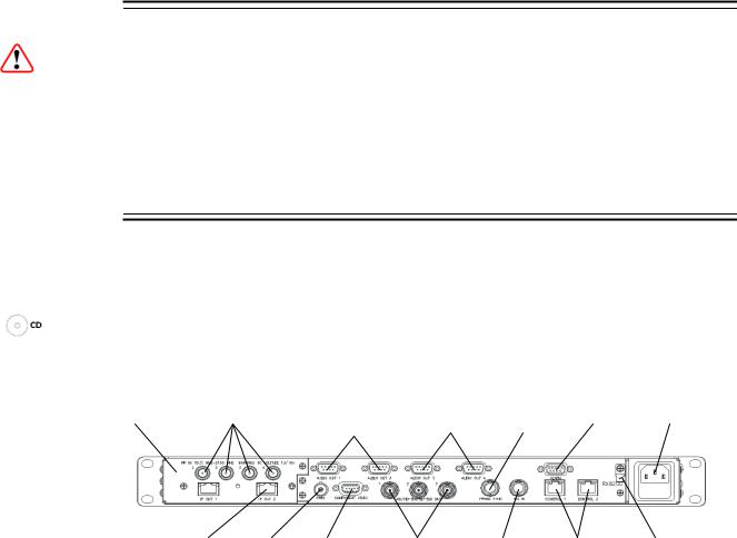
2.4Rear Panel Connectors
Always use the specified cables supplied for signal integrity and compliance with EMC requirements (see the Reference Guide).
Note: Rear panel connectors may differ, depending on the options selected.
INPUT MODULE |
RF IN 1-4 |
AUDIO OUT (1) AUDIO OUT (2) |
FRAME |
ALARM |
AC POWER |
|||||
|
|
|
|
1-2 |
3-4 |
SYNC |
|
|
|
|
|
|
|
|
|
|
|
|
|
|
|
RX8200 |
|
|
|
|
|
|
|
|
|
|
Sample configuration |
|
|
|
|
|
|
|
|
|
|
with: Satellite input, |
|
|
|
|
|
|
|
|
|
|
frame sync, HD video |
|
|
|
|
|
|
|
|
|
|
output, IP Transport |
|
|
|
|
|
|
|
|
|
|
Stream output and 2x |
|
|
|
|
|
|
|
|
|
|
Audio output modules |
|
|
|
|
|
|
|
|
|
|
|
|
|
|
|
|
|
|
|
|
|
installed. |
|
IP OUT 1-2 CVBS COMPONENT |
ASI/HD-SDI/SD- ASI INPUT CONTROL |
TECHNICAL |
||||||
|
|
|
|
VIDEO |
SDI OUT 1-3 |
|
1-2 |
EARTH |
||
|
|
|
|
|
|
|
|
|
|
|
|
|
|
|
|
|
|
|
|
|
|
|
Figure 1 |
Rear Panel Connectors |
|
|
|
|
||||
|
Table 4 |
Types of Connector |
|
|
|
|
|
|
||
|
|
|
|
|
|
|
||||
|
Type of Connector |
Description |
|
|
|
|
||||
|
|
|
|
|||||||
|
RF IN 1,2,3 & 4 |
F-type connectors for DVB or DVB-S2 modulated input |
|
|||||||
|
|
|
|
feed. |
|
|
|
|
|
|
|
|
|
|
|
||||||
|
AUDIO OUT 1,2,3 & 4 |
9-way male D-type connectors for analogue and |
|
|
||||||
|
|
|
|
balanced digital audio output. |
|
|
|
|
||
|
|
|
|
|
||||||
|
FRAME SYNC |
75 Ω BNC connector for frame synching input. |
|
|
||||||
|
|
|
|
|
||||||
|
ALARM |
|
9-way male D-type connector for alarm signal output. |
|
||||||
|
|
|
|
|||||||
|
IP OUT 1 & 2 |
8-way RJ-45 connectors for 1000BaseT IP output feed & |
|
|||||||
|
|
|
|
de-encapsulated IP data |
|
|
|
|
||
|
|
|
|
|
||||||
|
CVBS |
|
75 Ω BNC connector for SD composite video output. |
|
||||||
|
|
|
|
|||||||
|
COMPONENT VIDEO |
9-way male D-type connectors for component video |
|
|||||||
|
|
|
|
output. |
|
|
|
|
|
|
|
|
|
|
|
|
|
|
|
|
|
10 (44) |
EN/LZT 790 0009 R1A 2011-03-30 |
|
Installing the Equipment |
|
|
|
|
Type of Connector |
Description |
|
|
|
|
ASI/SD-SDI/HD-SDI |
75 Ω BNC connector for ASI or SDI (user selectable) |
|
OUT 1 , 2 & 3 |
output feeds. |
|
|
|
|
ASI INPUT |
75 Ω BNC connector for ASI input feed. |
|
|
|
|
CONTROL 1 & 2 |
8-way RJ-45 connectors for 10/100BaseT Ethernet |
|
|
control and monitoring. |
|
|
|
|
AC POWER |
IEC100-120 V AC / 220-240 V AC power input. |
|
|
|
|
TECHNICAL EARTH |
Spade connector for unit technical earth. |
|
|
|
|
2.5Connecting the Receiver to the Power Supply
Warning!
Do not overload wall outlets and extension cords as this can result in a risk of fire or electric shock.
As no mains switch is fitted to this unit, ensure the local power supply is switched OFF before connecting the supply cord.
The receiver is not fitted with an on/off switch. Ensure that the socket-outlet is installed near the equipment so that it is easily accessible. Failure to isolate the equipment properly may cause a safety hazard.
Connect the receiver to the power supply as follows:
1.Ensure the power supply is isolated and switched off.
2.Ensure the correct fuse type and rating has been fitted to both the equipment and the power cable.
3.Connect the lead to the receiver input connector and then to the power supply.
4.Switch on the power supply.
Table 5 Fuse Type and Rating
Power Supply
100-120 V AC / 220-240 V AC
Fuse Type and Rating
IEC/EN 60127-2 Sheet 5
Bussmann S505/Littelfuse 215
2 A 250 V T HBC
Note: Refer to the Reference Guide for all power supply, fuse replacement, safety, EMC information and operating conditions.
EN/LZT 790 0009 R1A 2011-03-30 |
11 (44) |

Quick Start Guide: Connect-Power-Configure
3 Quick Start Guide: Connect-Power-Configure
3.1Connecting the Receiver
The following points should be noted when making signal connections to the receiver:
•For models with option RX8200/HWO/DVBS2 fitted, connect the incoming satellite RF feed to the rear panel connector marked RF IN 1 - 4.
•For models with option RX8200/HWO/IP/GIGE fitted, connect the incoming MPEG Transport Stream over IP inputs to the rear panel connectors IP IN 1 -2.
•For models with option RX8200/HWO/G703 fitted, connect the incoming E3 or DS-3 ATM inputs to the rear panel connector G703.
•If you have an incoming ASI feed, this should be connected to the ASI Input.
•Decoded PAL or NTSC video is output on connector CVBS.
•Decoded analogue or digital audio is output on connectors AUDIO OUT 1, 2, 3 or 4. Adaptor cables are used to provide the connector type required for the installation.
•ASI OUT 1, 2 or 3 may output a Transport Stream, this can be manipulated/ generated in many ways according to the customer’s requirements. Connectors may also be configured as SDI/HDSDI.
•For models with option RX8200/HWO/IP/OUT fitted, the incoming feed is also routed through the unit and output on connectors IP OUT 1 and IP OUT 2.
•If the unit is to be controlled by Web browser or PC based control system then the control PC should be connected to connector CONTROL 1 or CONTROL 2.
•If the unit is to be used to decrypt (non-Director) encrypted feeds then a Conditional Access Module and card should be inserted in the slot labeled
Conditional Access Interface in the front panel.
3.2Powering the Receiver
3.2.1Switching On
Caution!
This equipment should not be operated unless the cooling fans are working and there is free-air flow around the unit.
1. Connect all signal and power cables to the rear panel of the unit.
12 (44) |
EN/LZT 790 0009 R1A 2011-03-30 |

Quick Start Guide: Connect-Power-Configure
2. Switch on the AC power supply to the unit at the wall or rack outlet.
Note: The RX8200 Receiver does NOT contain a power on/off switch.
3.After a short period of initialization the following screen is displayed on the Front Panel:
INITIALIZING 4.3.2 (Bank 0)
4.During initialization, confirm that the Status LED is on and all Up, Down, Left, Right, Edit and Save pushbuttons are lit.
3.2.2Power Up Operating Modes
When the equipment is switched on it will assume the control mode that was set when the power was turned off. This could be either:
• Local Front Panel/Web Browser control
• Director NCP control.
3.3Configuring the Inputs
3.3.1Transport Stream (ASI) Input
To configure the unit for ASI input:
1.Select ASI input from sub-menu Select Input.
3.3.2Satellite (DVB-S or DVB-S2) Input (if fitted)
Ensure that the incoming feed is connected to connector RF IN 1.
To configure the unit for Satellite input, navigate to the front panel Input menu Source # Configure menu and carry out the following steps:
1.Select SAT input
2.Set the LNB frequency
3.Set the Satellite frequency
4.Set the Symbol Rate
5.Set the Modulation scheme and FEC
6.Set the Roll-Off
7.Set the set the LNB power output
EN/LZT 790 0009 R1A 2011-03-30 |
13 (44) |

Quick Start Guide: Connect-Power-Configure
8. Set the set the LNB power output level
A description of each of these User Settings can be found in the Reference Guide.
Note: If the unit has successfully locked to the incoming feed, then the TS Lock value in menu Input should be LOCKED.
3.3.3IP (GIGE) Input (if fitted)
Ensure that the incoming feed is connected to connector IP IN 1.
To configure the unit for IP GIGE input, navigate to the front panel Input menu and carry out the following steps:
1.Select IP input
2.Set the Network 1 (and Network 2, if used) IP Address
3.Set up the MAC Mode parameters
4.Set up I/P Ports settings
5.Set up Stream 1/Unicast 1 (and Stream 2/Unicast 2, if used) settings
6.Set up Alarms/Alerts settings as required.
A description of each of these User Settings can be found in the Reference Guide.
Note: If the unit has successfully locked to the incoming feed, then the TS Lock value in menu Input should be LOCKED.
3.3.4G.703 (ATM) Input (if fitted)
Ensure that the incoming feed is connected to connector G703.
To configure the unit for G.703 ATM input, navigate to the front panel Input menu and carry out the following steps:
1.Select G703 input
2.Set the Mode
3.Set up Destuffing/Deinterleaver
4.Set up Reed Solomon/Derandomiser
5.Set up Man Packet Length Ctrl/Packet Length Size
6.Set up ATM Delta/ATM Alpha settings
7.ATM Descrambling/Header Correction
8.ATM Header Error Ignore ATM VPI
14 (44) |
EN/LZT 790 0009 R1A 2011-03-30 |
Loading...