

Page 1
SERVICE MANUAL
Color Inkjet Printer
Epson WF-R5690 series/ Epson WF-R4640 series
Epson WF-R5190 series/Epson WF - R1111 series
CONFIDENTIAL
SEMF14-003
Page 2

Notice:
All rights reserved. No part of this manual may be reproduced, stored in a retrieval system, or transmitted in any form or
by any means, electronic, mechanical, photocopying, recording, or otherwise, without the prior written permission of
SEIKO EPSON CORPORATION.
All effort have been made to ensure the accuracy of the contents of this manual. However, should any errors be
detected, SEIKO EPSON would greatly appreciate being informed of them.
The contents of this manual are subject to change without notice.
The above not withstanding SEIKO EPSON CORPORATION can assume no responsibility for any errors in this
manual or the consequences thereof.
EPSON is a registered trademark of SEIKO EPSON CORPORATION.
Note :Other product names used herein are for identification purpose only and may be trademarks or r egistered
trademarks of their respective owners. EPSON disclaims any and all rights in those marks.
Copyright 2014 SEIKO EPSON CORPORATION
Printer CS Quality Assurance Department
Confidential
Page 3

Safety Precautions
All safety procedures described here shall be strictly adhered to by all parties servicing and maintaining this
product.
DANGER
Strictly observe the following cautions. Failure to comply could result in serious bodily injury or loss of life.
1. Always disconnect the product from the power source and peripheral devices when servicing the product or
performing maintenance.
2. When performing works described in this manual, do not connect to a power source until instructed to do so.
Connecting to a power source causes high voltage in the power supply unit and some electronic components
even if the product power switch is off. If you need to perform the work with the power cable connected to a
power source, use extreme caution to avoid electrical shock.
WARNING
Strictly observe the following cautions. Failure to comply may lead to personal injury or loss of life.
1. Always wear protective goggles for disassembly and reassembly to protect your eyes from ink in working. If
any ink gets in your eyes, wash your eyes with clean water and consult a doctor immediately.
2. When using compressed air products; such as air duster, fo r cleaning during repair and maintenance, the use
of such products containing flammable gas is prohibited.
PRECAUTIONS
Strictly observe the following cautions. Failure to comply may lead to personal injury or damage of the product.
1. Repairs on Epson product should be performed only by an Epson certified repair technician.
2. No work should be performed on this product by persons unfamiliar with basic safety knowledge required for
electrician.
3. The power rating of this product is indicated on the serial number/rating plate. Never connect this product to
the power source whose voltages is different from the rated voltage.
4. Replace malfunctioning components only with those components provided or approved by Epson;
introduction of second-source ICs or other non-approved components may damage the product and void any
applicable Epson warranty.
5. The capacitors on the Main Board may be electrically charge right after the power turns off or after driving
motors which generates counter electromotive force such as when rotating the PF Roller or when moving the
CR Unit. There is a risk to damage the Main Board if the Head FFC is short-circuited with the capacitors on
the Main Board electrically charged, therefore, after the power turns off or after motors are driven, leave the
printer untouched for approximately 30 seconds to discharge the capacitors before starting disassembly/
reassembly.
6. To prevent the circuit boards from short-circuiting, be careful about the following when handing FFC or
cables.
When handling FFC, take care not to let the terminal section of FFC touch metal parts.
When connecting cables/FFC to the connectors on circuit board, connect them straight to the connectors to avoid
slant insertion.
Confidential
Page 4

7. In order to protect sensitive microprocessors and circuitry, use static discharge equipment, such as anti-static
wrist straps, when accessing internal components.
8. Do not tilt this product immediately after initial ink charge, especially after performing the ink charge several
times. Doing so may cause ink to leak from the product because it may take some time for the waste ink pads
to completely absorb ink wasted due to the ink charge.
9. Never touch the ink or wasted ink with bare hands. If ink comes into contact with your skin, wash it off with
soap and water immediately. If you have a skin irritation, consult a doctor immediately.
10. When disassembling or assembling this product, make sure to wear gloves to avoid injuries from metal parts
with sharp edges.
11. Use only recommended tools for disassembling, assembling or adjusting the printer.
12. Observe the specified torque when tightening screws.
13. Be extremely careful not to scratch or contaminate the following parts.
Nozzle plate of the printhead
CR Scale
PF Scale
ASF Scale
Coated surface of the PF Roller
Gears
Rollers
LCD
Scanner Sensor
Exterior parts
14. Never use oil or grease other than those specified in this manual. Use of different types of oil or grease may
damage the component or give bad influence on the printer function.
15. Apply the specified amount of grease described in this manua l .
16. Make the specified adjustments when you disassemble the printer.
17. When cleaning this product, follow the procedure described in this manual.
18. When transporting this product after filling the ink in the printhead, pack the printer without removing the
ink cartridges in order to prevent the printhead from drying out.
19. Make sure to install antivirus software in the computers used for the service support activities.
20. Keep the virus pattern file of antivirus software up-to-date.
21. When disassembling/reassembling this product, if you find adhesive power of the double-sided tape which
secure the parts or FFC is not enough, replace the tape with new one and attach it correctly to the specified
points where the parts or FFC should be secured.
22. Unless otherwise specified in this manual, the labels attached on the returned product should be transferred to
the corresponding attachment positions on the new one referring to the labels on the returned product.
Confidential
Page 5
About This Manual
This manual, consists of the following chapters, is intended for repair service personnel and includes information
necessary for properly performing maintenance and servicing the product.
CHAPTER 1. TROUBLESHOOTING
Describes the step-by-step procedures for the troubleshooting.
CHAPTER 2. DISASSEMBLY / REASSEMBLY
Describes the disassembly/reassembly procedures for main parts/units of the product, and provide the
standard operation time for servicing the product.
CHAPTER 3. ADJUSTMENT
Describes the required adjustments for servicing the product.
CHAPTER 4. MAINTENANCE
Describes maintenance items and procedures for servicing the product.
CHAPTER 5. APPENDIX
Provides the additional information for reference:
Symbols Used in this Manual
Various symbols are used throughout this manual either to provide additional information on a specific topic or
to warn of possible danger present during a procedure or an action. Pay attention to all symbols when they are
used, and always read explanation thoroughly and follow the instructions.
Indicates an operating or maintenance procedure, practice or condition that, if not strictly observed,
could result in serious injury or loss of life.
Indicates an operating or maintenance procedure, practice, or condition that, if not strictly observed,
could result in bodily injury, damage or malfunction of equipment.
May indicate an operating or maintenance procedure, practice or condition that is necessary to
accomplish a task efficiently. It may also provide additional information that is related to a specific
subject, or comment on the results achieved through a previous action.
For Chapter 4 “Disassembly/Reassembly”, symbols other than indicated above are used to show additional
information for disassembly/reassembly. For the details on those symbols, see "2.3 Disassembly and Assembly
Procedure (p46)".
Confidential
Page 6

Revision Status
Revision Date of Issue Description
A August 27, 2014 First Release
B December 19, 2014 Revise the content
Chapter 1
Made change in "1.1.5.1 Start method of Maintenance Special Mode (p28)".
Chapter 2
Made change in "2.2 Parts Diagram (p38)".
Disassembling procedure has been added in "2.3.2.1 Panel Unit (p48)"
Made change the picture of "2.3.4.6 Decompress Pump Unit (p81) ".
Made change for description in "2.3.4.8 Printhead (p85)".
Made change for description in "2.3.4.9 Ink Supply Unit (p90)".
Made change for description in "2.3.4.10 Head FFC (p96)".
Made change for description in "2.3.4.11 Ink Supply Assy (p98)"
Made change for description in "2.3.4.12 CR Scale (p104)".
Made change for description in "2.3.4.14 CR Guide Frame Assy (p109)".
Made change the picture of "2.3.4.15 Frame Base Assy (p113)".
Made change for description in "2.3.4.16 Star Wheel Assy (p114)".
Made change for description in "2.3.4.17 Front Frame Assy (p115)".
Made change for description in "2.3.4.18 EJ Roller (p118)".
Made change for description in "2.3.5.1 Ink Supply BK Cover Assy (p121)".
Made change for description in "2.3.5.2 Ink Supply CL Cover Assy (p123)".
Made change for description in
Made change for description in
Made change for description in
Made change for description in
Made change for description in "2.3.5.7 Ink Supply BK Assy (p134)".
Made change for description in "2.3.5.8 Ink Supply CL Assy (p136)".
Made change for description in "2.3.5.9 Ink Pack Holder (BK) (p140)".
Made change for description in "2.3.5.10 Ink Pack Holder (Y/M/C) (p142)".
Description about "2.3.5.11 Ink Supply Needle (p144)" has been added.
Description about "2.3.5.12 Ink tube (p144)" has been added.
Made change for description in "2.3.6.1 ADF Rear Cover (p146)".
Made change for description in "2.3.6.2 ADF Cover Assy (p147)".
Made change for description in
Made change for description in "2.3.6.4 ADF LD Assy (p148)".
Checkpoint of " 2nd Cassette Unit (p152)" has been added.
Made change for description in "2.3.7.2 Paper Stopper Assy 1st/2nd (p154)".
Description about "2.3.7.3 Pick Up Roller Assy 1st (p156)" has been added.
Made change for description in
Made change for description in
Chapter 3
Information of new inspection jig has added to "3.2.5 Ink Leak check (p204)".
Made change in "3.2.7 Touch Panel Adjustment (WF-R5690/R4640 series
only) (p218)".
Chapter 4
Delete the Firmware Update Procedure.
Made change in "4.3 Initialization of Admin Password (p226)".
"2.3.5.3 Releasing the Ink Supply BK Assy (p125)"
"2.3.5.4 Releasing the Ink Supply CL Assy (p128)"
"2.3.5.5 Ink Supply BK Cover Open Sensor (p131)"
"2.3.5.6 Ink Supply CL Cover Open Sensor (p132)"
"2.3.6.3 ADF Document Support Assy (p147)"
"2.4.15 Ink Supply BK Assy (p181)"
"2.4.16 Ink Supply CL Assy (p182)"
.
.
.
.
.
.
.
Confidential
Page 7

Epson WF-R5690/R4640/R5190 series Revision B
Contents
Chapter 1 Troubleshooting
1.1 Troubleshooting....................................................................................................................................................... 11
1.1.1 Troubleshooting Workflow ............................................................................................................................ 11
1.1.2 Power-On Sequence ....................................................................................................................................... 13
1.1.3 Fatal Error....................................................................................................................................................... 15
1.1.4 FAX Troubleshooting..................................................................................................................................... 20
1.1.4.1 FAX Log ................................................................................................................................................ 20
1.1.4.2 Error Code/Superficial Phenomenon-Based Troubleshooting .............................................................. 26
1.1.5 Status sheet .................................... .......................................................................... ....................................... 28
1.1.5.1 Start method of Maintenance Special Mode....................................... ........................................ ........... 28
1.1.5.2 Description of Status sheet (Non-disclosed information to user).......................................................... 29
Chapter 2 DISASSEMBLY/REASSEMBLY
2.1 O verview ................................................................................................................................................................. 32
2.1.1 Tools ............................................................................................................................................................... 32
2.1.2 Screw types used in the printer..................................... .................................................................................. 33
2.1.3 Standard Operation Time for servicing the product ....................................................................................... 33
2.2 Parts Diagram .......................................................................................................................................................... 38
2.3 D isassembly and Assembly Procedure.................................................................................................................... 46
2.3.1 Preparation for servicing ................................................................................................................................ 46
2.3.1.1 Unlocking the Carriage Assy................................................................................................................. 46
2.3.1.2 Parts/Units Need to be Removed in Advance........................................................................................ 47
2.3.2 Exterior parts (WF-R5690/R4640 series)....................................................................................................... 48
2.3.2.1 Panel Unit .............................................................................................................................................. 48
2.3.2.2 Speaker................................................................................................................................................... 50
2.3.2.3 Housing Rear Assy ................................................................................... ............................................. 51
2.3.2.4 FAX Cover............................................................................................................................................. 52
2.3.2.5 ADF/Scanner Unit ................................................................................................................................. 53
2.3.2.6 Front Housing Assy ............................................................................................................................... 55
2.3.2.7 Middle Housing ..................................................................................................................................... 57
2.3.3 Exterior parts (WF-R5190 series) ................................................................................................................... 59
2.3.3.1 Panel Unit .............................................................................................................................................. 59
2.3.3.2 Housing Upper............................................................................... ........................................................ 61
2.3.3.3 Housing Rear Assy ................................................................................... ............................................. 63
2.3.3.4 USB Cover............................................................................................................................................. 64
2.3.3.5 Front Housing Assy ............................................................................................................................... 65
2.3.3.6 Middle Housing ..................................................................................................................................... 67
2.3.4 Printer Mechanism.................................................. ........................................................................................ 69
2.3.4.1 Main Board Unit .................................................................................................................................... 69
2.3.4.2 Main Board ............................................................................................................................................ 74
2.3.4.3 Power Supply Unit................................................................... ... ........................................................... 76
2.3.4.4 Rear ASF Assy......................................................................... .............................................................. 77
2.3.4.5 Rear ASF Guide Upper................................ .......................................................................................... 79
2.3.4.6 Decompress Pump Unit..................................................... ..................................... ... ............................ 81
2.3.4.7 PF Encoder............................................................................................................................................. 83
2.3.4.8 Printhead ................................................................................................................................................ 85
2.3.4.9 Ink Supply Unit...................................................................................................................................... 90
2.3.4.10 Head FFC............................................................................................................................................. 96
2.3.4.11 Ink Supply Assy................................................................................................................................... 98
2.3.4.12 CR Scale ................................ ..................................... .................................... ................................... 104
Troubleshooting 7
Confidential
Page 8

Epson WF-R5690/R4640/R5190 series Revision B
2.3.4.13 Ink System ................................................. ......................................................................... ............... 106
2.3.4.14 CR Guide Frame Assy ........................................................ ............................................................... 109
2.3.4.15 Frame Base Assy .............................................................................................................................. . 113
2.3.4.16 Star Wheel Assy............................................................................................................... .................. 114
2.3.4.17 Front Frame Assy ............................................................................................................................... 115
2.3.4.18 EJ Roller ............................................................................................................................................ 118
2.3.5 I nk Supply Mechanism............................................................................................................................. .... 121
2.3.5.1 Ink Supply BK Cover Assy ................................................................................................................. 121
2.3.5.2 I nk Supply CL Cover Assy.................................................................................................................. 123
2.3.5.3 Releasing the Ink Supply BK Assy..................................................................................................... . 125
2.3.5.4 Releasing the Ink Supply CL Assy...................................................................................................... 128
2.3.5.5 I nk Suppl y BK Cover Open Sensor..................................................................................................... 131
2.3.5.6 Ink Supply CL Cover Open Sensor ..................................................................................................... 132
2.3.5.7 I nk Supply BK Assy ............................................................................................................................ 134
2.3.5.8 I nk Supply CL Assy............................................................................................................................. 136
2.3.5.9 Ink Pack Holder (BK).......................................................................................................................... 140
2.3.5.10 Ink Pack Holder (Y/M/C) .................................................................................................................. 142
2.3.5.11 Ink Supply Needle .................................. ...................................................................... ..................... 144
2.3.5.12 Ink tube ..................................... ......................................................................... ................................ 144
2.3.6 A DF/Scanner Unit ........................................................................................................................................ 146
2.3.6.1 ADF Rear Cover ........................................................................................................................... ....... 146
2.3.6.2 ADF Cover Assy......................................................................................................................... ......... 147
2.3.6.3 ADF Document Support Assy...............................................................................................
2.3.6.4 ADF LD Assy ...................................................................................................................................... 148
2.3.6.5 Scanner Unit .................................. .................................... ...................................... ............................ 149
2.3.7 2 nd Cassette Unit.......................................................................................................................................... 152
2.3.7.1 2nd Cassette Unit .......................................................................................................................... ....... 152
2.3.7.2 Paper Stopper Assy 1st/2nd ............................................................................................... .................. 154
2.3.7.3 Pick Up Roller Assy 1st................................................................. ...................................................... 156
2.3.7.4 Pick Up Roller Assy 2nd ................................................................................................... .................. 157
2.4 Routing FFCs/Cables ................................................................................................................................ ............ 160
2.4.1 Top of the Scanner Unit...................................................................................................... .......................... 160
2.4.2 Bottom of the Frame Base............................................................................................................................ 160
2.4.3 Bottom of the Scanner Unit
(WF-R5690/R4640 series)...................................................................................................................................... 161
2.4.4 Inside of the FAX Cover (WF-R5690/R4640 series)................................................................................... 162
2.4.5 Front of the Printer .............................................................................................................................. ......... 164
2.4.6 Center of the Printer ..................................................................................................................................... 166
2.4.7 Bottom of the Ink System Unit.......................................................................... ........................................... 168
2.4.8 Carriage Assy ............................................................................................................................................... 170
2.4.9 Speaker Cable ......................................................... ..................................... ................................................. 170
2.4.10 Around the Main Board Assy (1) ................................................................................................... ............ 171
2.4.11 Around the Main Board Assy (2) ................................................................................................... ............ 174
2.4.12 Around the Main Board Assy (3) ................................................................................................... ............ 176
2.4.13 2nd Cassette Housing Assy ........................................................................................................................ 176
2.4.14 CRCM FFC................................................................................................................................................. 180
2.4.15 Ink Supply BK Assy................................................................................................................................... 181
2.4.16 Ink Supply CL Assy ................................................................................................................................... 182
.............. 147
Chapter 3 Adjustment
3.1 Required Adjustments ........................................................................................................................................... 185
3.2 ......................................................................................................................................... .Details of Adjustments 192
3.2.1 PF Timing Belt Tension Check ..................................................................................................... ............... 192
3.2.2 Rear ASF Timing Belt Tension Check......................................................................................................... 193
3.2.3 PG Adjustment ............................................................................................................................................. 195
3.2.3.1 Preparation ........................................................................................................................................... 196
3.2.3.2 PG Adjustment procedure.................................................................................................................... 199
3.2.4 Checking the Platen Gap .............................................................................................................................. 203
Troubleshooting 8
Confidential
Page 9

Epson WF-R5690/R4640/R5190 series Revision B
3.2.5 Ink Leak check.............................................................................................................................................. 204
3.2.6 H ead Angular Mechanism Adjustment. ....................................................................................................... 212
3.2.6.1 P reparation of the Head Angular Adjustment ...................................................................................... 212
3.2.6.2 Adjustment Procedure.................................... ....................................................................... ............... 214
3.2.7 Touch Panel Adjustment (WF-R5690/R4640 series only)........................................................................... 218
Chapter 4 Maintenance
4.1 O verview .......................................................................................................................................... ..................... 222
4.1.1 Cleaning........................................................................................................................................................ 222
4.1.2 Lubrication.................................................................................................................................................... 222
4.2 Lubrication Points and Instruction................................................... ................................................................. .... 223
4.3 Initialization of Admin Password................................................................................................ .......................... 226
Chapter 5 Appendix
5.1 Connector Diagram ............................................................................................................................................... 229
5.2 Protection for transportation...................................................................................................................... ............ 230
5.2.1 Pasting the packing material to the Holder Slider Ink pack Assy................................................................ 230
Troubleshooting 9
Confidential
Page 10

CHAPTER 1
TROUBLESHOOTING
Confidential
Page 11
Epson WF-R5690/R4640/R5190 series Revision B
Finish
*
Turn on the printer
2
What is returned reason?
Copy an image
Copy an image by ADF
Start
ADF/Scanner
failure
Printer failure only
Yes
Yes
Yes
No
Does power-on
sequence start?
Is power-on sequence
finished without error?
Yes
No
Is ADF operation
finished without
trouble?
Standby condition
Is scanning operation
finished without
trouble?
ADF failure?
1
No
Is the print result OK?
Yes
Yes
Is printing complete
without an error?
4
No
3
No
5
No
6
No
*: In case of “Not Trouble Found”, check fatal error code.
(p12)
(p12)
(p12)
(p12)
(p12)
(p12)
Print a nozzle check pattern
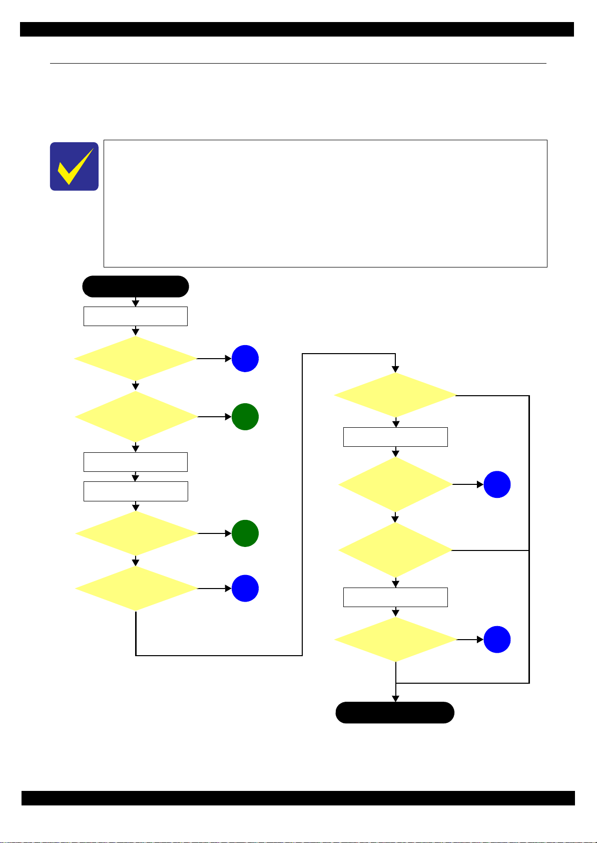
1.1 Troubleshooting
This section describes the troubleshooting workflow.
1.1.1 Troubleshooting Workflow
The following page describes the troubleshooting workflow. Follow the flow when troubleshooting problems.
This flowchart is compiled based on the following contents.
• Our experience regarding the quality problem.
• ESK’s repair data
• Printer Mechanism specification for WF-R5690/R4640/R5190 series
WF-R5190 series are not equipped with the Scanner / ADF unit, therefore, the
troubleshooting related to the Scanner / ADF unit is not applied.
If the reason for the return is evident, first check the phenomenon user claims recurs,
then proceed to the troubleshooting.
Figure 1-1. Troubleshooting Workflow (1)
Troubleshooting Troubleshooting 11
Confidential
Page 12
Epson WF-R5690/R4640/R5190 series Revision B
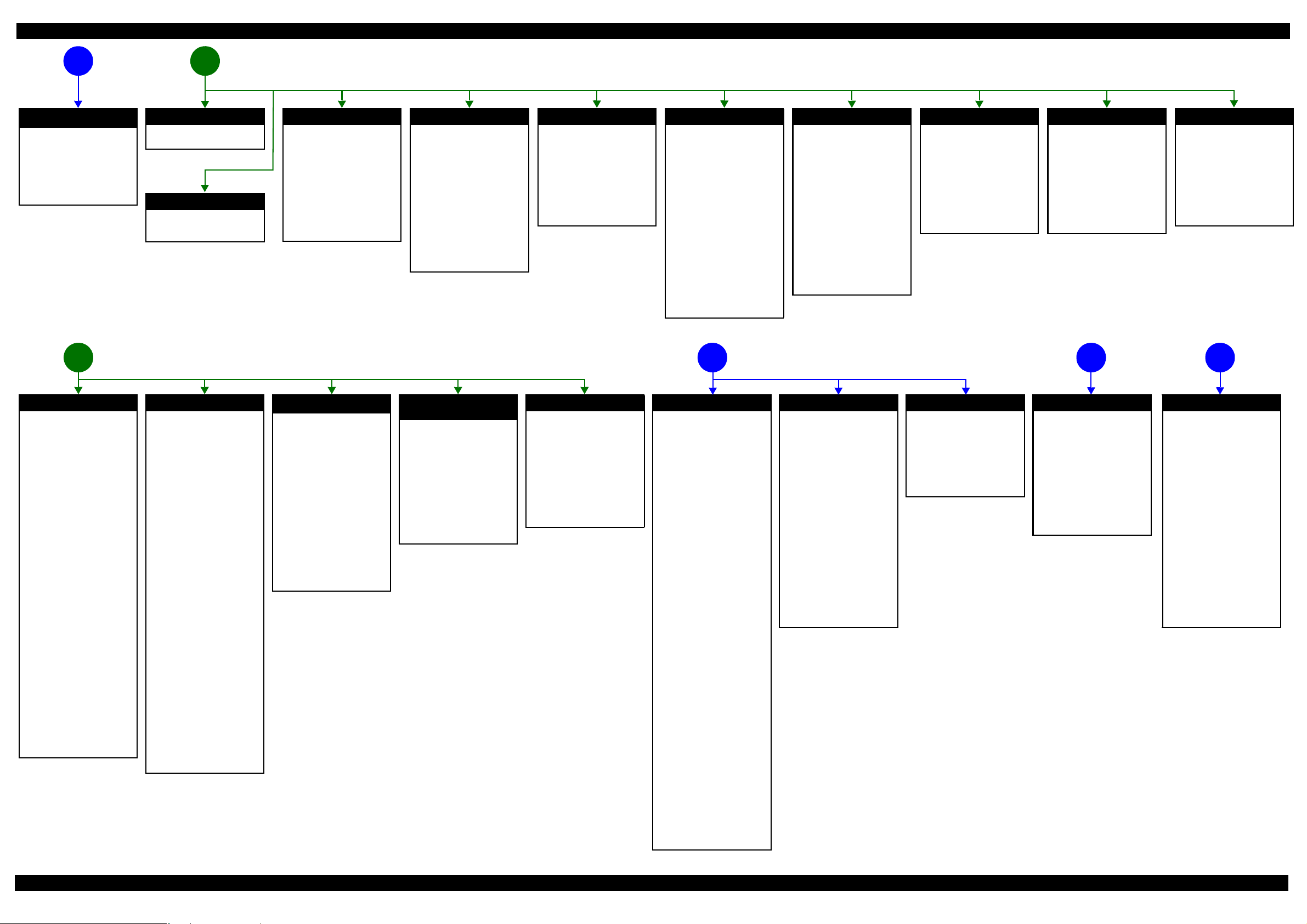
The power-on sequence
does not start (p11)
No power
[Presumable Cause]
• Damage to Power Supply Unit
• Damage to Main Board
• Damage to Panel Unit
[Remedy]
• Replace Power Supply Unit
• Replace Main Board
• Replace Panel Unit
*1
Error is indicated during printing nozzle check pattern. (p11)
Error is indicated during power-on
21
sequence (p11)
Fatal error
See "1.1.2Power-On Sequence
(p13)".
Paper jam error
See "Paper jam error" which
occurs during nozzle check
pattern printing.
Maintenance box full
[Occurrence Condition]
This error occurs when
maintenance counter in
Maintenance Box exceeds the
specified value.
[Occurrence Timing]
•At power-on
• When printing starts
•Cleaning
• When closing the Front Cover
[Remedy]
• Replace Maintenance Box
Maintenance box CSIC error
[Occurrence Condition]
This error occurs when
Maintenance Box data is incorrect
or cannot be recognized correctly.
[Occurrence Timing]
• At power-on
• When printing starts
•Cleaning
• When closing the Front Cover
[Remedy]
• Remove and reinstall
Maintenance Box
• Replace Maintenance Box
• Replace CSIC terminal
• Replace Maintenance Box FFC
• Replace Main Board
No maintenance box error
[Occurrence Condition]
This error occurs when
Maintenance Box is not installed.
[Occurrence Timing]
• At power-on
• When printing starts
• Cleaning
• When closing the Front Cover
[Remedy]
• Install Maintenance Box
Ink end error
[Occurrence Condition]
This error occurs when ink in Ink
Cartridge is empty.
[Occurrence Timing]
• At power-on
• When printing starts
• Cleaning
• When closing the Front Cover
• During printing
[Remedy]
• Replace Ink Cartridge
[Note]
If this error occurs during
printing, the paper will be ejected
automatically after the current
page is printed. If the error occurs
during face printing in the
automatic duplex printing, the
current page will be printed but
printing stops before reversing the
paper.
Problems related to print result or during printing (p11)
Ink cartridge detection error
[Occurrence Condition]
This error occurs when ink
cartridge data is incorrect or Ink
Cartridge is not recognized
correctly.
[Occurrence Timing]
• At power-on
• When printing starts
• Cleaning
• When closing the Front Cover
• During printing
[Remedy]
• Remove and reinstall Ink
Cartridges
• Replace Ink Cartridge
• Replace CSIC terminal
• Replace CSIC Board
• Replace CSIC FFC
• Replace Main Board
No ink cartridge error
[Occurrence Condition]
This error occurs when Ink
Cartridge is not installed.
[Occurrence Timing]
• At power-on
• When printing starts
• Cleaning
• When closing the Front Cover
• During printing
[Remedy]
• Install Ink Cartridge
Front cover open error
[Occurrence Condition]
This error occurs when Front
Cover is open.
[Occurrence Timing]
• At power-on
• During printing
[Remedy]
• Close Front Cover
• Replace Front Housing Assy
• Replace Cover Open Sensor
• Replace Main Board
Scanning cannot be
performed
5 643
successfully (p11)
Ink cover open error
[Occurrence Condition]
This error occurs when Ink Cover
is open.
[Occurrence Timing]
• At power-on
• During printing
[Remedy]
• Close Ink Cover
• Replace Cover Open Sensor
• Replace Main Board
ADF does not
operate
normally (p11)
Paper jam error
[Occurrence Condition]
This error occurs when the top/
bottom of paper cannot be
detected by PE Sensor or PW
Sensor within the specified steps
even if the paper has been fed
correctly.
[Occurrence Timing]
• At power-on
• During feeding paper
• During ejecting paper
• During duplex printing
• When closing the Front Cover
[Remedy]
1 Press the “Start” button to eject
jammed paper.
• If succeeded
Print starts if there is printing
data.
• If failed
The paper jam error occurs
again.
2 If failed at Step 1, open the
Front Cover and remove the
Duplex Unit, and then remove
jammed paper.
3 Press the “Start” button again.
• If succeeded
Paper is fed if there is
printing data.
• If failed
The paper jam error occurs
again.
4 Check the following if failed in
Step 3.
• Foreign object
• Detached parts
• PE Sensor Lever
•PE Sensor
•PW Sensor
• Main Board
• Paper Stopper Assy
Paper out error
[Occurrence Condition]
This error occurs when the top of
paper cannot be detected by PE
Sensor within the specified steps
even if the paper has been fed
correctly. (No paper / paper
loading failed / paper is fed at
slant)
[Occurrence Timing]
• During feeding paper
[Remedy]
1 Set paper to 1st cassette or
Rear MP Tray, and press the
“Start” button.
2 If a paper stops before reaching
PE Sensor, remove it and
check the paper condition.
3 A)If paper has no damage, set
edge guide correctly after
setting paper in 1st cassette
or Rear MP Tray, and
perform Step 2 again.
B) If paper is damaged, check
for foreign materials /
detached parts / deformed
parts in the paper path.
4 If the problem is not solved by
3-A) & 3-B), check the
following.
• Foreign object
• Detached parts
• Movement of Trigger Lever
of Rear ASF
• Tension of ASF Timing Belt
• Surface condition of LD
Roller of Rear ASF, Pickup
Roller and paper feed rollers
in Duplex Unit
• PE Sensor Lever
•PE Sensor
• Main Board
•PF Motor
• Cassette Assy
• Paper Stopper Assy
Multi-feed error
[Occurrence Condition]
This error occurs on the following
case.
• A paper is ejected without
printing during paper loading
operation.
• Actual paper length is longer
than theoretical one.
[Occurrence Timing]
• During feeding paper
• During loading paper
• During ejecting paper
[Remedy]
• Replace PE Sensor Lever
• Replace PE Sensor
• Replace PW Sensor
• Replace Main Board
• Perform the operation check
and replace Paper Stopper
Assy if necessary
*2
Paper length mismatch error
for duplex printing
[Occurrence Condition]
This error occurs when actual
paper size is not matched to
theoretical one (both shorter and
longer).
[Occurrence Timing]
• During auto duplex printing
• During receiving FAX data
[Remedy]
• Replace PE Sensor Lever
• Replace PE Sensor
• Replace PW Sensor
• Replace Main Board
No paper cassette error
[Occurrence Condition]
This error occurs when Cassette
Assy 1st cannot be detected. (The
error occurs to the Cassette Assy
2nd in the same way.)
[Occurrence Timing]
• During feeding paper
*3
[Remedy]
• Check connection for Paper
Stopper Lever Sensor cable
• Replace Paper Stopper Lever
Sensor
Printing failure
[Symptoms]
• Printing failure
• Contamination on paper
• Dot missing
• Paper is ejected without printing
[Presumable Cause]
• Incorrect setting for driver/
panel
• Contamination on CR Scale
• Contamination on Printhead
Cover
• Printhead failure
• Dot missing of Printhead
• Contamination on Cap or
Wiper of Ink System Unit
• Ink System Unit failure
• PG is narrow
• Damage on PE Sensor Lever
• Damage on PE Sensor
• Damage on APG related parts
of Carriage Assy
• APG Lever operation failure
• Connection failure between
Decompress Pump Tube and
Ink Supply Unit
• Twist or blockade of
Decompress Pump Tube
• Decompress Pump Unit
operation failure
• Ink Supply Unit operation failure
• Connection failure between
Ink Supply Tube and Printhead
[Remedy]
• Check driver or panel setting
• Replace CR Scale
• Clean Printhead Cover
• Perform cleaning
• Replace Ink Cartridge
• Replace Printhead
• Clean rubber part of Cap
• Replace Ink System Unit
• Adjust PG again
• Replace Printer Mechanism
• Replace PE Sensor Lever
• Replace PE Sensor
• Replace Carriage Assy
• Check the attachment
condition of APG Lever
• Check the condition of
Decompress Pump Tube
• Replace Decompress Pump Unit
• Replace Ink Supply Unit
• Check the condition of the joint
section of Ink Supply Tube
Paper feeding failure
[Presumable Cause]
• Use of 3rd party media
• Inappropriate position of edge
guide
• Foreign object
• Detached parts
• Contamination on LD Roller of
Rear ASF / Retard Roller
• Contamination on Pickup
Roller
• Contamination on paper feed
rollers in Duplex Unit
• Damage to Cassette Assy
• Rear ASF Timing Belt tension
failure
• Damage to Rear ASF Assy
[Remedy]
• Use EPSON-recommended
paper
• Set edge guide correctly
• Remove foreign material
• Re-install parts
• Replace Pickup Assy
• Replace Cassette Assy
• Replace Printer Mechanism
• Replace Rear ASF Assy
Note *1: If the printer can turn on but turns off right away, the protection circuit may cut off the power due
Abnormal noise
[Presumable Cause]
• Foreign object
• Insufficient grease
• Damage to gears
[Remedy]
• Remove foreign material
• Apply an appropriate amount
of grease
• Replace gears
to an error such as a circuit failure.
*2: Only for manual duplex printing.
*3: WF-R5690/R4640 series only.
Scanner failure
[Presumable Cause]
• Contamination on document
glass
• Contamination on Document
Pad
• CIS bonding failure
• CIS failure
• Damage to Scanner Motor
[Remedy]
• Clean document glass
• Clean Document Pad
• Replace Document Pad
• Replace CIS Unit
• Replace Scanner Motor
ADF failure
[Symptoms]
• Paper is not fed
• Multi-feed
• Paper jam
• Skewed document
[Presumable Cause]
• Deterioration of Pickup Roller
• Deterioration of ADF Pad
Assy
• Damage to gears
•Damage to ADF Motor
• Contamination on document
glass
• Foreign object
• Damage to ADF Cover Assy
• Deterioration of Paper Eject
Roller
• Damage to ADF Document
Sensor / ADF PE Sensor
[Remedy]
• Replace ADF Cover Assy
• Replace ADF Pad Assy
• Clean document glass
• Remove foreign material
• Replace ADF Unit
Troubleshooting Troubleshooting Workflow 12
Confidential
Page 13
Epson WF-R5690/R4640/R5190 series Revision B
0
0
0
0
0
0
0
0
0
0
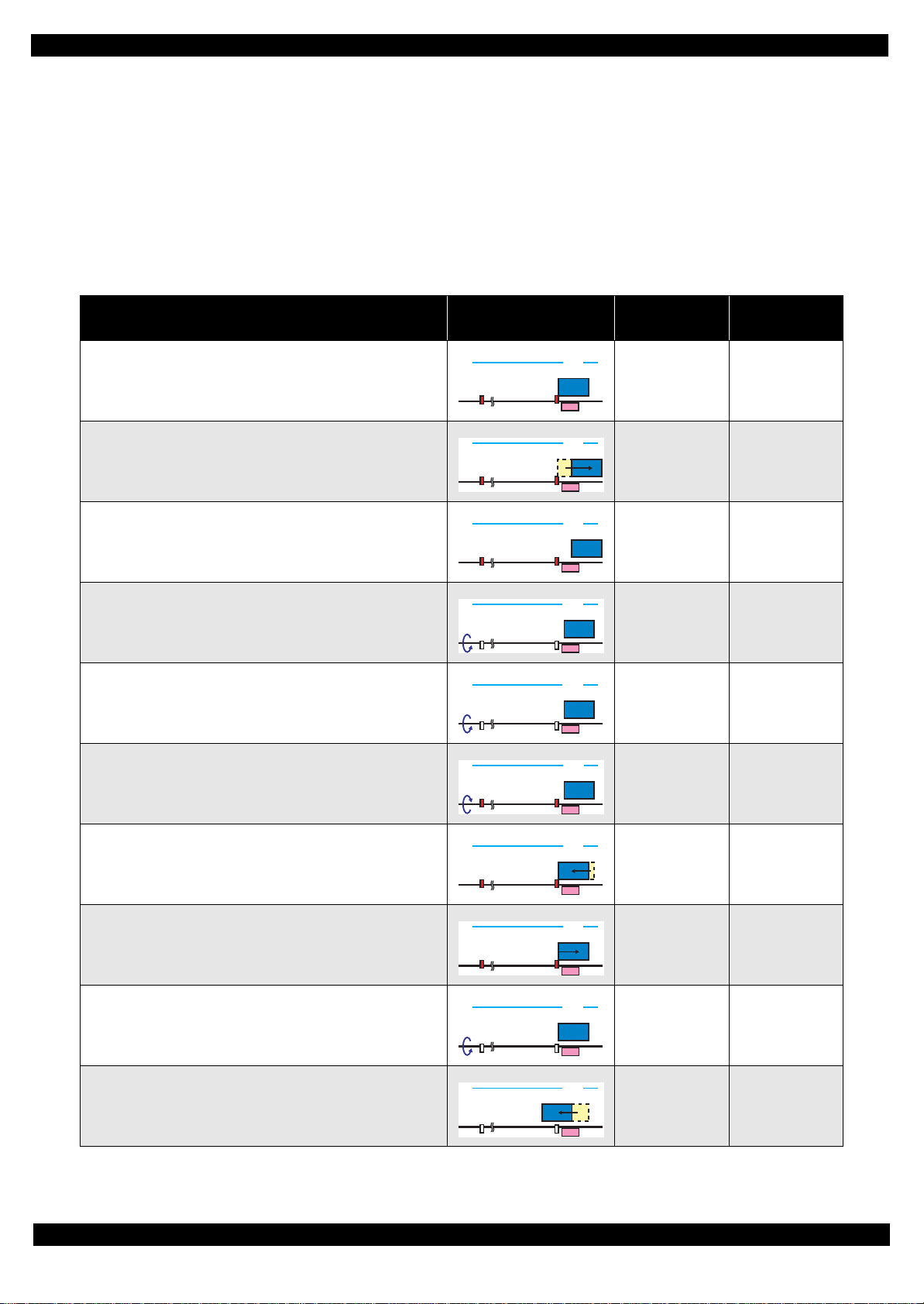
1.1.2 Power-On Sequence
This section describes the power-on sequences for this product. The preconditions are as follows.
Turning on the printer after turning it off without an error.
Initial ink charge has finished and every cartridge has sufficient ink.
No paper on the paper path.
The Printhead is capped by the cap of Ink System and the CR Lock is engaged normally.
The carriage is locked by the CR lock.
PG position is set to PG1.
Table 1-1. Power-On Sequence
Operation
1. Printhead initialization and fuse inspection
1-1.Initializes the Printhead, and checks the fuse on the printer
control circuit board.
2. Seeking the home position
2-1.The carriage moves to the 0-digit side slowly and confirms it
touches the Right Frame.
2-2.Regards the position where the carriage touches the Right Frame
as the position of the specified steps from the home position, and
set it as the origin position.
2-3.The carriage slowly moves the CR lock set position.
2-4.The PF Motor rotates clockwise and releases the CR lock.
2-5.The PF Motor rotates counterclockwise and sets the CR lock.
Movement of
Components
80
80
80
80
80
80
HP
HP
HP
HP
HP
HP
Front ASF drive
condition
OFF ---
↓
↓
↓
↓
↓
Decompress
motor
---
---
---
---
---
2-6.The carriage moves to the 80-digit side slowly and confirms it
touches the CR lock.
2-7.The carriage returns to its home position.
2-8.The PF Motor rotates clockwise and releases the CR lock.
3. Switching front ASF drive
3-1.The carriage moves to the 80-digit side slowly up to position
where the Front ASF turn on.
80
80
80
80
HP
HP
HP
HP
↓
↓
↓
---
---
---
ON ---
Troubleshooting 13
Confidential
Page 14
Epson WF-R5690/R4640/R5190 series Revision B
0
0
0
0
0
0
0
0
0
0
0
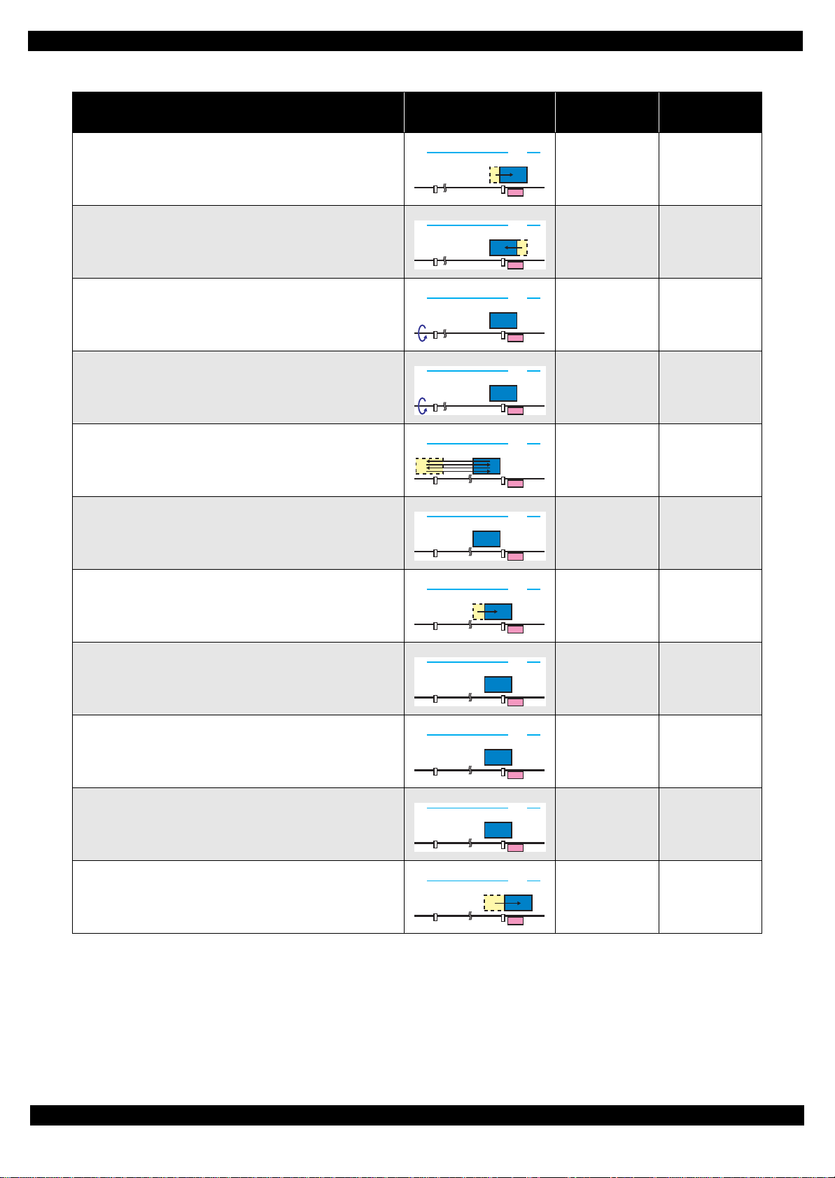
Table 1-1. Power-On Sequence
Operation
3-2.The carriage moves to the 0-digit side slowly up to the position
where the Front ASF turn off.
3-3.The carriage moves to the 80-digit side slowly and passes by the
CR lock.
4. PF initialization
4-1.The PF Motor rotates clockwise for approximately one second.
4-2.The PE sensor checks if paper exists, and the PF Motor rotates
clockwise for approximately 0.5 seconds.
5. Low temperature operation sequence
5-1.The carriage moves back and forth between CR lock and the left
Frame two times.
6. Checking waste ink overflow
6-1.Reads out the waste ink counter value of the Maintenance Box
to check waste ink overflow.
Movement of
Components
80
80
80
80
80
80
HP
HP
HP
HP
HP
HP
Front ASF drive
condition
OFF ---
↓
↓
↓
↓
↓
Decompress
motor
---
---
---
---
---
7. Detecting ink cartridge and initializing ink system
7-1.The carriage moves slowly to the ink detection position.
80
HP
↓
7-2.The Decompress Motor is driven and Diaphragm Pump sucks
the ink in the ink cartridges.
80
HP
↓
Decompress
and vent to
atmosphere
7-3.While monitoring the ink end sensor, the Decompress Motor is
driven again and the Diaphragm Pump sucks the ink.
80
HP
↓
Decompress
and vent to
atmosphere
7-4.Detects the ink remaining.
80
HP
↓
7-5.The carriage returns to its home position.
80
HP
↓
Note *1: On the premise on this table, PG does not change and the Rear ASF does not operate during the sequence.
*2: Executes when the detected temperature is under 5 ℃ (41)by the thermistor on the Printhead.
*3: The Printhead is capped with the Cap of the Ink System but the Carriage is not locked by the CR lock in order to shorten the
time before printing starts. The Carriage is locked when the printer enters the power saving mode without any operation after it
is turned on.
---
---
---
Troubleshooting 14
Confidential
Page 15
Epson WF-R5690/R4640/R5190 series Revision B
1.1.3 Fatal Error
This section describes the fatal error code and the possible cause for this product.
Fatal Error List
Fatal errors related to the ADF/Scanner unit do not occur for WF-R5190 series because this
model does not have ADF/Scanner unit.
Table 1-2. Fatal Error List
Error type
ADF/
Scanner
Error
code
0x01 ADF PID excess speed error
0x02 ADF PID reverse error
0x03 ADF PID lock error • ADF Encoder failure (contaminated/detached scale, Encoder Board
0x04 ADF PID acceleration lock detection error
0x05 ADF PID excess load error
0x06 ADF PID driving time error • Main Board failure
0x09 ADF BS+ excess speed error
0x0A ADF BS+ reverse error
0x0B ADF BS+ lock error • ADF Encoder failure (contaminated/detached scale, Encoder Board
0x0D ADF BS+ excess load error
0x0E ADF BS+ driving time error • Main Board failure
0x10 HP detection error
0x11 Contact detection distance exceeded error
0x12
0x13
0x14 Measurement failure error • Scanner drive mechanism was overloaded.
0x20 LED light error
Opposite side contact detection distance
exceeded error
Opposite side wrong contact detection
distance error
Error name Possible cause
• ADF Encoder failure (contaminated/detached scale, Encoder Board
failure)
• Motor driver failure (Main Board failure)
• ADF Encoder failure (contaminated/detached scale, Encoder Board
failure)
• Paper jam
failure)
• ADF Motor failure
• Paper jam
• Cable disconnection
• ADF Encoder failure (contaminated/detached scale, Encoder Board
failure)
• Motor driver failure (Main Board failure)
• ADF Encoder failure (contaminated/detached scale, Encoder Board
failure)
• Paper jam
failure)
• ADF Motor failure
• ADF drive overload (paper jam/foreign object)
• Cable disconnection
• CIS Unit failure
• Scanner Housing failure
• Main Board failure
• CIS Unit failure
• Scanner Housing failur e (Including wrong attachment of the origin mark)
• Main Board failure
• Scanner FFC failure / Scanner FFC connection failure
• Scanner Motor failure / Scanner Motor connection failure
• CIS Unit failure
• Scanner Housing failur e (Including wrong attachment of the origin mark)
• Main Board failure
• Scanner FFC failure / Scanner FFC connection failure
• Scanner Motor failure / Scanner Motor connection failure
• CIS Unit failure
• Scanner housing failure (In cluding wrong attachment of the origin mark)
• Main Board failure
• Scanner FFC failure / Scanner FFC connection failure
• Scanner Motor failure / Scanner Motor connection failure
• CIS Unit failure
• Main Board failure
Troubleshooting 15
Confidential
Page 16
Epson WF-R5690/R4640/R5190 series Revision B
Table 1-2. Fatal Error List
Error type
ADF/
Scanner
PDL 0x5F Main ROM and μSD ROM matching error • Mismatch the Main ROM FW version and μSD ROM FW version.
Printer
Error
code
0x30 Option error • Main Board failure
0x36 Paper jam error
0x41 FB PID excess speed error
0x42 FB PID reverse error
0x43 FB PID lock error • ADF Encoder failure (contaminated/detached scale, Encoder Board
0x44 FB PID acceleration lock
0x45 FB PID excess load error
0x46 FB PID driving time error • Main Board failure
0x49 FB BS+ excess sped error
0x4A FB BS+ reverse error
0x4B FB BS+ lock error • ADF Encoder failure (contaminated/detached scale, Encoder Board
0x4D FB BS+ excess load error
0x4E FB BS+ driving time error • Main Board failure
0x51 Automatic judgement fatal error 1
0x52 Automatic judgement fatal error 2
0x53 Automatic judgement fatal error 3
0x54 Automatic judgement fatal error 4
0x55 Automatic judgement fatal error 5
0x60 HP error
0x61 Deadlock avoidance error
0x62 Impossible contact detection error
0x6B PF runaway error
0x7F Inspection mode error ---*
0x8D Factor error other than printer device
0x8E Driver mismatch error An unsupported driver was used.
0x8F EEPROM verify error (by command) ---*
0x90 PW Sensor failure error • PW sensor failure
0x91 PW Sensor detected foreign object error
0x92 Hot plug disconnection paper jam error
0x93 PE Sensor error
Error name Possible cause
• Paper jam
• Foreign object
• ADF Encoder failure (contaminated/detached scale, Encoder Board
failure)
• Motor driver failure (Main Board failure)
• ADF Encoder failure (contaminated/detached scale, Encoder Board
failure)
• Paper jam
failure)
• ADF Motor failure
• ADF drive mechanism overload (assembling failure, lubrication failure)
• Cable disconnection
• ADF Encoder failure (contaminated/detached scale, Encoder Board
failure)
• Motor driver failure (Main Board failure)
• ADF Encoder failure (contaminated/detached scale, Encoder Board
failure)
failure)
• ADF Motor failure
• ADF drive mechanism overload (assembling failure, lubrication failure)
• Cable disconnection
---*
• Paper jam
• Foreign object
• Deformation of the Main Frame
• PF Encoder failure (contaminated/detached scale, Encoder Board failure)
• Motor drive error
This error occurs if the printer becomes a fatal error status due to a failure of
parts other than the printer such as the scanner or ADF
• Main Board failure
• Foreign object
• 2nd Cassette Unit has been removed during feeding (when the ASF
Motor is operating).
• Contact failure of the connector which contacts 2nd Cassette Unit and the
printer.
• PE Sensor failure
• Main Board failure
Troubleshooting 16
Confidential
Page 17
Epson WF-R5690/R4640/R5190 series Revision B
Table 1-2. Fatal Error List
Error type
Printer
Error
code
0x94 PW Sensor light value adjust error
0x96 Decompr e ss pu m p mo tor driving time error
0x97 Head drive circuit VBS over-voltage error
0x99 IES process check error ---*
0x9A Circuit error (include blowout of a fuse)
0x9B Transistor temperature error
0x9C X-Hot detect error (pre printing)
0x9D X-Hot detect error (after flushing)
0x9E Head temperature error
0x9F No print inspection mode error ---*
0xB8 CRCM access error
0xB9 -
0xBA
0xBD -
0xC2
0xC3 Ink device error
0xC4 -
0xCF
0xD1 ASF PID excess load error
0xD2 ASF PID excess speed error
0xD3 ASF PID reverse error
0xD4 ASF PID lock error
0xD8 ASF load position reverse error
0xD9 ASF load position excess speed error
Ink device error
CRCM access error
CRCM access error
Error name Possible cause
• PW Sensor failure
• Main Board failure
• Decompress pump motor failure
• Main Board failure
• Head FFC failure
• Main Board failure
• Main Board failure
• Printhead failure
• Main Board failure
• CR Contact Module failure
• CRCM FFC disconnection
• Main Board failure
• Ink cartridge failure
• CSIC Terminal failure
• CR Contact Module failure
• Main Board failure
• CR Contact Module failure
• CRCM FFC disconnection
• Main Board failure
• Ink cartridge failure
• CSIC Terminal failure
• CR Contact Module failure
• Main Board failure
• CR Contact Module failure
• CRCM FFC disconnection
• Main Board failure
• ASF Encoder failure (contaminated/detached scale, Encoder Board
failure)
• ASF Motor failure
• Pickup Roller (2nd cassette) drive mechanism overload (paper jam /
foreign object)
• Cable disconnection
• ASF Encoder failure (contaminated/detached scale, Encoder Board
failure)
• Motor driver failure (Main Board failure)
• ASF Encoder failure (contaminated/detached scale, Encoder Board
failure)
• Paper jam
• ASF Encoder failure (contaminated/detached scale, Encoder Board
failure)
• ASF Motor failure
• Pickup Roller (2nd cassette) drive mechanism overload (paper jam /
foreign object)
• Cable disconnection
• ASF Encoder failure (contaminated/detached scale, Encoder Board
failure)
• Paper jam
• ASF Encoder failure (contaminated/detached scale, Encoder Board
failure)
• Motor driver failure (Main Board failure)
Troubleshooting 17
Confidential
Page 18

Epson WF-R5690/R4640/R5190 series Revision B
Table 1-2. Fatal Error List
Error type
Printer
Error
code
0xDA ASF load position excess load error
0xDE ASF PID driving time error
0xDF ASF load position driving time error
0xE1 CR PID excess load error
0xE2 CR PID excess speed error
0xE3 CR PID reverse error
0xE4 CR PID lock error
0xE5 CR PID speed fall error
0xE8 CR load position reverse error
0xE9 CR load position excess speed error
0xEA CR load position excess load error
0xEE CR PID driving time error
0xEF CR load position driving time error
0xF1 PF PID excess load error
0xF2 PF PID excess speed error
0xF3 PF PID reverse error
Error name Possible cause
• ASF Encoder failure (contaminated/detached scale, Encoder Board
failure)
• ASF Motor failure
• Pickup Roller (2nd cassette) driven mechanism overload (paper jam/
foreign object)
• Cable disconnection
• Main Board failure
• CR Encoder failure (contaminated/detached scale, Encoder board failure)
• CR Motor failure
• Carriage overload error (paper jam/foreign object)
• Cable disconnection
• CR Encoder failure (contaminated/detached scale, Encoder board failure)
• Motor driver failure (Main Board failure)
• Tooth skip of the CR Timing Belt
• Improper tension of the CR Timing Belt
• CR Encoder failure (contaminated/detached scale, Encoder board failure)
• Tooth skip of the CR Timing Belt
• Improper tension of the CR Timing Belt
• Paper jam
• CR Encoder failure (contaminated/detached scale, Encoder Board failure)
• CR Motor failure
• Carriage overload error (paper jam/foreign object)
• Cable disconnection
• CR Encoder failure (contaminated/detached scale, Encoder Board failure)
• Motor driver failure (Main Board failure)
• Tooth skip of the CR Timing Belt
• Improper tension of the CR Timing Belt
• Paper jam
• CR Encoder failure (contaminated/detached scale, Encoder Board failure)
• Tooth skip of the CR Timing Belt
• Improper tension of the CR Timing Belt
• Paper jam
• CR Encoder failure (contaminated/detached scale, Encoder Board failure)
• Motor driver failure (Main Board failure)
• Tooth skip of the CR Timing Belt
• Improper tension of the CR Timing Belt
• CR Encoder failure (contaminated/detached scale, Encoder Board failure)
• CR Motor failure
• Carriage overload error (paper jam/foreign object)
• Cable disconnection
• Main Board failure
• PF Encoder failure (contaminated/detached scale, Encoder Board failure)
• PF Motor failure
• PF drive mechanism overload (paper jam/foreign object)
• Cable disconnection
• PF Encoder failure (contaminated/detached scale, Encoder Board failure)
• Motor driver failure (Main Board failure)
• Tooth skip of the PF T i ming Belt
• Improper tension of the PF Timing Belt
• PF Encoder failure (contaminated/detached scale, Encoder Board failure)
• Tooth skip of the PF T i ming Belt
• Improper tension of the PF Timing Belt
• Paper jam
Troubleshooting 18
Confidential
Page 19
Epson WF-R5690/R4640/R5190 series Revision B
Table 1-2. Fatal Error List
Error type
Printer
Error
code
0xF4 PF PID lock error
0xF8 PF load position reverse error
0xF9 PF load position excess speed error
0xFA PF load position excess load error
0xFE PF PID driving time error
0xFF PF load position driving time error
Inspection Mode Error List
Error name Error indication Remedy
Error name Possible cause
• PF Encoder failure (contaminated/detached scale, Encoder Board failure)
• PF Motor failure
• PF driver mechanism overload (paper jam/foreign object)
• Cable disconnection
• PF Encoder failure (contaminated/detached scale, Encoder Board failure)
• Tooth skip of the PF T i ming Belt
• Improper tension of the PF Timing Belt
• PF Encoder failure (contaminated/detached scale, Encoder Board failure)
• Motor driver failure (Main Board failure)
• Tooth skip of the PF T i ming Belt
• Improper tension of the PF Timing belt
• PF Encoder failure (contaminated/detached scale, Encoder Board failure)
• PF Motor failure
• PF driver mechanism overload (paper jam/foreign object)
• Cable disconnection
• Main Board failure
Table 1-3. Inspection Mode Error List
Fatal Error Fatal Error (Error Code:0xXX) Refer to Table 1-2 "Fatal Error List" (p.15)
Paper Jam Error Paper Jam Error Remove the jammed paper, close the cover.
No Paper Error Paper Out Error Set the paper, close the cover.
No Tray / Cassette Error Cassette Nothing Set the Cassette.
Ink Case Open Error Ink Cover Open Error Close the ink cover.
Cover Open Error Cover Open Error Close the Cover.
Carriage Outside error Outside Carriage Lock the CR unit.
No ink Cartridge Error Ink Out Error Replace the ink pack.
Ink Cartridge Abnormal Error Ink Out Error Replace the ink pack.
Ink Cartridge Non-Genuine Error Ink Out Error Replace the ink pack.
Initial Charge Error Ink out Error Replace the ink pack.
Ink Error Ink Out Error Replace the ink pack.
Ink End Error Ink Out Error Replace the ink pack.
Print Error Ink Out Error Replace the ink pack.
Maintenance Box Nothing Error Maintenance Box Nothing Error Replace the Maintenance Box
Maintenance Box CSIC Error Maintenance Box CSIC Error Replace the Maintenance Box.
Maintenance Box Full Error Maintenance Box Full Error Replace the Maintenance Box.
Double Feed Error Paper Piled Out Error Remove the jammed paper, close the cover
Fax Paper length Mismatch Error Other Error Set the specified paper.
Auto duplex paper length Mismatch Error Paper Size Error (Duplex) TBD
Paper Mismatch Error (Logical) Other Error TBD
Duplex Printing Error Cant Dup Media TBD
Memory Overflow Error Other Error TBD
Manual Feed Command Error Manual Feed Error TBD
Diver Mismatch Error Other Error TBD
Troubleshooting 19
Confidential
Page 20
Epson WF-R5690/R4640/R5190 series Revision B
Item Information
Communication
Start date / time
Year/month/day/hour/minute
Communication type Sending/receiving/polling reception
Communication ID
Sending/polling reception:
• Destination name of speed dial (first 20 characters)
• Telephone number (last 20 characters)
• Destination fax ID (20 characters)
Receiving:
• Destination fax ID (20 characters)
Airtime Hour/minute/second
Communication
pages
0 to 100
Communication
result
Common:
Normal/cancel/error code*
Sending/polling reception:
No dial tone detected/No fax signal detected/Busy tone detected
1.1.4 FAX Troubleshooting
1.1.4.1 FAX Log
When an error related to fax occurs, it is not only indicated on LCD but also saved as a log file. The error code is
recorded in it, and according to this log, the contents of the error can be confirmed.
Table 1-4. FAX Log (1)
Log Name Description Save Destination
Latest log
(Last Transaction)
*1
The latest communication log of sending / polling reception Nonvolatile memory
The following information is stored.
Communication log
(Fax Log)
Note *: For error codes, see Table 1-2 "Fatal Error List" (p.15).
Power failure log
(Fax Log)
Note *1: The latest communication log for all destinations are printed in a list from when the sequential broadcast is executed.
*2: The power failure log when the sequential broadcast is being executed is not printed for the destinations to which the
*2
Cancellation is treated as a normal termination, ther efore, if it is cancelled, the latest log is printed when the aut o print s etting is
“always print”, and not printed when the setting is “only when an error occurs”. If “only when an error occurs” is selected, the
log is printed even when an error occurs for just one destination.
transmission log is already complete then. If the power failure occurs before the scheduled sending time when a broadcast is
scheduled, the scheduled sending time is recorded.
The information stored in this log is the same as the communication log.However, since the
airtime is “Unknown” in this case, the result of it is recorded as “power failure”.
Nonvolatile memory
Nonvolatile memory
The communication log is not stored under the following conditions:
When the sending operation is canceled which storing B&W image or waiting for
Troubleshooting 20
redialing.
In the case of a power failure during the operation of sending/polling reception including
waiting status for redial, or during receive operation.
When the receiving operation is canceled before the fax signal is detected.
If the fax signal is not detected during receiving operation.
If cancelled during the sequential broadcast.
(The log for the destinations of “not dialed yet” or “waiting for redial” is not saved except
for those of which the communication is complete.)
Confidential
Page 21

Epson WF-R5690/R4640/R5190 series Revision B
Item Information
Communication start
date / time
Year/month/day/hour/minute
Communication Type Sending/receiving/polling reception
Communication ID
Sending/polling reception:
• Destination name of speed dial (first 20 characters)
• Telephone number (last 20 characters)
• Destination fax ID (20 characters)
Receiving:
• Destination fax ID (20 characters)
Airtime Hour/minute/second
Communication pages 0 to 100
Communication result
Common:
Normal/cancel/error code
Sending/polling reception:
No dial tone detected/No fax signal detected/Busy tone detected.
Diagnosing code 10 bytes
Protocol data
The latest 43 commands/responses*
• Time stamp
• Sending / receiving
• Command / response code
(See Table 1-7 "Command/Response Code" (p.24))
• FCF / FIF (first 33 octets)
Table 1-5. FAX Log (2)
Log Name Description Save Destination
The following information of the latest communication is stored.
Protocol trace
Volatile memory
Note *: If a large amount of FIF is received, the recorded command/response may
be less than 40.
FAX Error Codes
Table 1-6. Fax Error Code List
Error
Code
(HEX)
000 Successful completion (Monochrome) Complete OK
C000 Successful completion (Color) Complete OK Color
Troubleshooting 21
400 Communication error Communication error Error code
401 Communication error Communication error Error code
402 Communication error Communication error Error code
403 Communication error Communication error Error code
404 Communication error Communication error Error code
405 Communication error Communication error Error code
407 Communication error Communication error Error code
408 Communication error Communication error Error code
409 Communication error Communication error Error code
410 Communication error Communication error Error code
412 Communication error Communication error Error code
416 Communication error Communication error Error code
417 Communication error Communication error Error code
Phenomenon LCD Display Print Example
Confidential
Page 22

Epson WF-R5690/R4640/R5190 series Revision B
Table 1-6. Fax Error Code List
Error
Code
(HEX)
418 Communication error Communication error Error code
420
421 Communication error Communication error Error code
422 Communication error Communication error Error code
427 Communication error Communication error Error code
433 Communication error Communication error Error code
434 Communication error Communication error Error code
436 Communication error Communication error Error code
459 Communication error Communication error Error code
490 Communication error Communication error Error code
494 Communication error Communication error Error code
495 Communication error Communication error Error code
496 Communication error Communication error Error code
501 Communication error Communication error Error code
502 Communication error Communication error Error code
503 Communication error Communication error Error code
504 Communication error Communication error Error code
505 Communication error Communication error Error code
540 Communication error Communication error Error code
541 Communication error Communication error Error code
542 Communication error Communication error Error code
543 Communication error Communication error Error code
544 Communication error Communication error Error code
550 Communication error Communication error Error code
554 Communication error Communication error Error code
620 Communication error Communication error Error code
621 Communication error Communication error Error code
623 Communication error Communication error Error code
624 Communication error Communication error Error code
630 A busy tone was detected after dialing
631 Communication error Communication error Error code
632 Communication error Communication error Error code
633 Communication error Communication error Error code
634 A fax signal was not detected for a given length of time after dialing No Answer No Answer
637 A dial tone was not detected before dialing No Dial Tone No Dial Tone
638 A power failure occurred during communication No displayed Power Fail
700 The communication was canceled by an operation Canceled Canceled
706 System error System Error Error code
709 Communication error Communication error Error code
815 Communication error Communication error Error code
870 The image memory is full Memory Full Memory Full
Fax signal was not detected during receive operation. (The call was a
telephone call)
Phenomenon LCD Display Print Example
Not displayed ---
Talking
(Line Busy)
Talking
(Line Busy)
Troubleshooting 22
Confidential
Page 23

Epson WF-R5690/R4640/R5190 series Revision B
Table 1-6. Fax Error Code List
Error
Code
(HEX)
871 The maximum number of files was exceeded Error code Error code
873 Communication error Communication error Error code
874 Communication error Communication error Error code
875 Communication error Communication error Error code
880 System error System Error Error code
881 System error System Error Error code
882 System error System Error Error code
883 System error System Error Error code
884 System error System Error Error code
928 Collision (A call signal was detected when shifting to dial operation) Not displayed --F0B Communication error Communication error Error code
F1E Communication error Communication error Error code
F20 Communication error Communication error Error code
F21 System error System error Error code
F23 Communication error Communication error Error code
F24 Communication error Communication error Error code
F25 Communication error Communication error Error code
F27 System error System error Error code
F28 System error System error Error code
F29 Communication error Communication error Error code
F2A Communication error Communication error Error code
F2B No image data for reprint exists No Image --F2F System error System error Error code
F3A Communication error Communication error Error code
F51 System error System error Error code
F57 Communication error Communication error Error code
F58 Communication error Communication error Error code
F59 System error System error Error code
F60 A scanner fatal error occurs
F61 A printer fatal error occurs
F62 Reserved --- Error code
F63 ADF miss feed or paper jam occurred
F64 The memory for printing received image is full Error code Error code
Phenomenon LCD Display Print Example
Same message when a
scanner fatal error occurred*
Same message when a printer
fatal error occurred*
Same message when an ADF
fatal error occurred*
Error code
Error code
ADF Jam
Note *: Confirm the fatal error code with the Adjustment Program to che ck whic h error occu rre d.(Se e" 1.1.3 Fatal Error (p15)")
Troubleshooting 23
Confidential
Page 24
Epson WF-R5690/R4640/R5190 series Revision B
Command/response code
Table 1-7. Command/Response Code
Command/response
code
DIS 80 --- Digital Identification signal
CSI 40 --- Called Subscriber Identification
NSF 20 --- Non-Standard Facilities
DTC 81 --- Digital Transmit Command
CIG 41 --- CallInG subscriber identification
NSC 21 --- Non-Standard facilities Command
PWD C1 --- PassWorD
SEP A1 --- Selective Polling
Reserved (PSA) 61 --- Polled Sub Address
Reserved (CIA) E1 --- Calling subscriber Internet Address
Reserved (ISP) 11 --- Internet Selective Polling address
DCS 82 --- Digital Command Signal
TSI 42 --- Transmitting Subscriber Identification
NSS 22 --- Non-Standard facilities Set-up
SUB C2 --- SUB address
SID A2 --- Sender IDentification
TRN E6 --- Training
TCF F0 --- Training Check
CTC 12 --- Continue To Correct
Reserved (TSA) 62 --- Transmitting Subscriber internet Address
Reserved (IRA) E2 --- Internet Routing Address
CFR 84 --- ConFirmation to Receive
FTT 44 --- Failure To Train
CTR C4 --- Response for Continue To correct
Reserved (CSA) 24 --- Called Subscriber internet Address
EOM 8E --- End Of Message
MPS 4E --- Multi Page Signal
EOP 2E --- End Of Procedure
PRI-EOM 9E --- Procedure Interrupt-End Of Message
PRI-MPS 5E --- Procedure Interrupt-Multi Page Signal
PRI-EOP 3E --- Procedure Interrupt-End Of Procedure
Reserved (EOS) 1E --- End Of Selection
PPS-EOM BE 8E Partial Page Signal-End Of Message
PPS-MPS BE 4E Partial Page Signal-Multi Page Signal
PPS-EOP BE 2E Partial Page Signal-End Of Procedure
PPS-PRI-EOM BE 9E Partial Page Signal-Procedure Interrupt-End Of Message
PPS-PRI-MPS BE 5E Partial Page Signal-Procedure Interrupt-Multi Page Signal
PPS-PRI-EOP BE 3E
PPS-EOS BE 1E Partial Page Signal-End Of Selection
PPS-NULL BE 00 Partial Page Signal-part i al page boundary
EOR-EOM CE 8E End Of Retransmission-End Of Message
FCF value (HEX)
Content
First Second
Partial Page Signal-Procedure InterruptEnd Of Procedure
Troubleshooting 24
Confidential
Page 25

Epson WF-R5690/R4640/R5190 series Revision B
Table 1-7. Command/Response Code
Command/response
code
EOR-MPS CE 4E End Of Retransmission-Multi Page Signal
EOR-EOP CE 2E End Of Retransmission-End Of Procedure
EOR-PRI-EOM CE 9E
EOR-PRI-MPS CE 5E
EOR-PRI-EOP CE 3E
EOR-EOS CE 1E End Of Retransmission-End Of Selection
EOR-NULL CE 00 End Of Retransmission- partial page boundary
RR 6E --- Receive Ready
MCF 8C --- Message ConFirmation
RTP CC --- ReTrain Positive
RTN 4C --- ReTrain Negative
PIP AC --- Procedure Interrupt Positive
PIN 2C --- Procedure Interrupt Negative
PPR BC --- Partial Page Request
RNR EC --- Receive Not Ready
ERR 1C --- Response for End of Retransm issio n
Reserved (FDM) FC --- File Diagnostic Message
DCN FA --- DisCoNnect
CRP 1A --- Command RePeat
Reserved (FNV) CA --- Field Not Valid
PIX FF --- PIXel image
Space Other combinations Unknown command/response
FCF value (HEX)
First Second
End Of Retransmission-Procedure InterruptEnd Of Message
End Of Retransmission-Procedure InterruptMulti Page Signal
End Of Retransmission-Procedure InterruptEnd Of Procedure
Content
Troubleshooting 25
Confidential
Page 26

Epson WF-R5690/R4640/R5190 series Revision B
1.1.4.2 Error Code/Superficial Phenomenon-Based Troubleshooting
This section explains the troubleshooting procedures based on the error codes and superficial phenomenon.
When an error occurs, it may be displayed on the LCD panel with a message instead of
an error code. To check the error code, print out a fax log.
If the problem is not solved even after carrying out the remedy shown in the Table 1-8,
print out a protocol trace to analyze the cause of the error.
Table 1-8. Troubleshooting Based on the Error Code/Superficial Phenomenon
Error code (LCD Message)/
Phenomenon
Communication Error
(The error is indicated with error
code on the fax log.)
Line Busy The line is busy. Try again later.
No answer
Power fail
706,880-884,F21,F27F28,F2F,F51,F59
Memory full Out of Memory
871
F60 A scanner fatal error occurred
F61 A printer fatal error occurred
F62 Reserved ---
F63
F64
Cannot receive faxes
Cannot dial
Description Remedy
Turn off v.34 and try again.
Turn off ECM and try again.
When using xDSL, check the connection from “Line” jack to the fax via the
Communication error
The other end of the line does
not answer.
The other end of the line
answered but no answer tone is
detected.
Power failure occurred during
sending/receiving/printing/
redialing
A system error (fax circuit
failure)occurs
Maximum number of files is
exceeded.
ADF document mis-feed or
paper jam occurs
The memory for printing
received image is full
The telephone cable is not
connected properly.
The telephone line is not
working
Auto answer is set to ”N” Set to “Y”.
DRD setting is incorrect
Calling signal cannot be
detected.
The telephone cable is not
connected properly.
The telephone line is not
working
Pulse/Tone dial setting error Turn the setting to the other one and try again.
xDSL splitter.
When using TAM, check the connection from “Line” jack to the TAM via
the fax.
Check if the telephone line makes any sound.
Check the number and dial again.
Confirm the P/S Board Connector Cable or P/S Board is not damaged, and
retry
Replace the FAX board with a new one
ASK the sender to resend the fax in several batches.
See Table 1-2 "Fatal Error List" (p.15).
Set the documents and again.
If a paper jam error occurs, remove the jammed paper and try again.
Ask the sender to resend the fax in several batches.
Connect the telephone cable properly.
Verify if the phone line works by connecting to a phone to it.
Set the setting to “ALL” and try again.Should other ring patterns be selected,
contact the telephone company.
Contact the telephone company or obtain the fax log for more analysis.
Connect the telephone cable properly.
Verify if the phone line works by connecting to phone to it.
Troubleshooting 26
Confidential
Page 27

Epson WF-R5690/R4640/R5190 series Revision B
Table 1-8. Troubleshooting Based on the Error Code/Superficial Phenomenon
Error code (LCD Message)/
Phenomenon
Cannot receive/send faxed in
color
Cannot print all the received data
when printing data stored in
memory
Images run off the paper
Description Remedy
ECM is set to off. Set to on and try again.
Fax mode is set to “B&W only” Set to “B&W/Color”
The size of the memory is 2.0
Mbyte. If the data becomes over
the set threshold, oldest data are
deleted to make room for new
ones.
Auto reduction is set to off. Set auto reduction to on and reprint the data.
Paper size setting does not
match the size of the received
data.
Paper size setting does not
match the size of papers in the
tray.
Set auto reduction to on and reprint the data.
Choose the correct setting and reprint the data.
Choose the correct setting or load correct sized papers in the tray and reprint
the data.
Troubleshooting 27
Confidential
Page 28
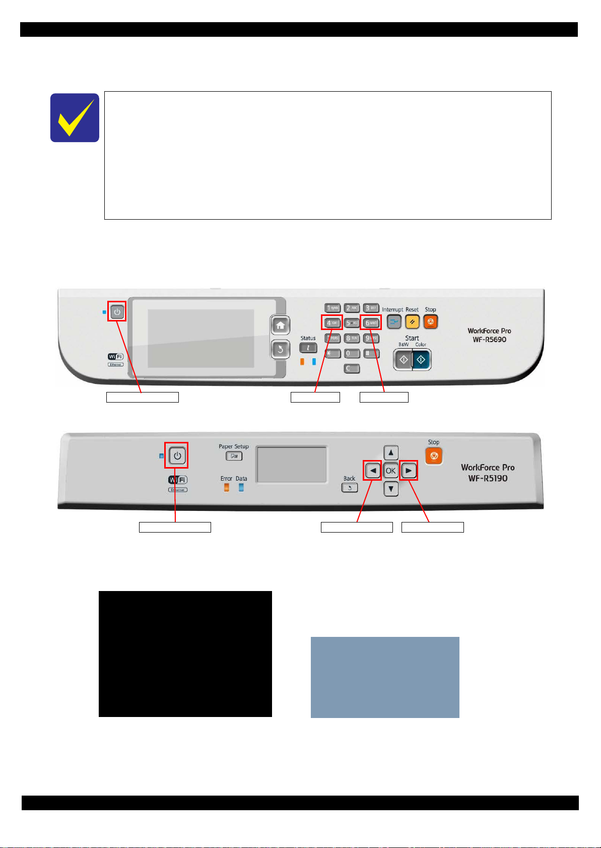
Epson WF-R5690/R4640/R5190 series Revision B
Power on button No.4 button No.6 button
Power on button Right buttonLeft button
Maintenance SP Mode
1. Status Sheet Print mode
Inspection Mode
1. STSheet Mode
[WF-R5690/R4640 series]
[WF-R5190 series]
Run: Color / Select: [3][6]
1.1.5 Status sheet
This section describes the Status sheet for this product.
This product can print the three kind of status sheet, and you can confirm the following
information.
• C o nfiguration Status Sheet
• Supply Status Sheet
• Usage History Sheet
This product has Non-disclosed information to user.
This information can be displayed on the Status sheet by starting the product with the
Inspection Mode.
1.1.5.1 Start method of Maintenance Special Mode
1. From a power off status, push the following buttons until the message is displayed on LCD.
WF-R5690/R4640 series
WF-R5190 series
2. Select the following items from the Inspection menu.
WF-R5690/R4640 series: “1. Status Sheet Print Mode”
WF-R5190 series: “1. STSheet Mode”
3. The product starts as usual.
4. Print the status sheets.
Troubleshooting 28
Confidential
Page 29
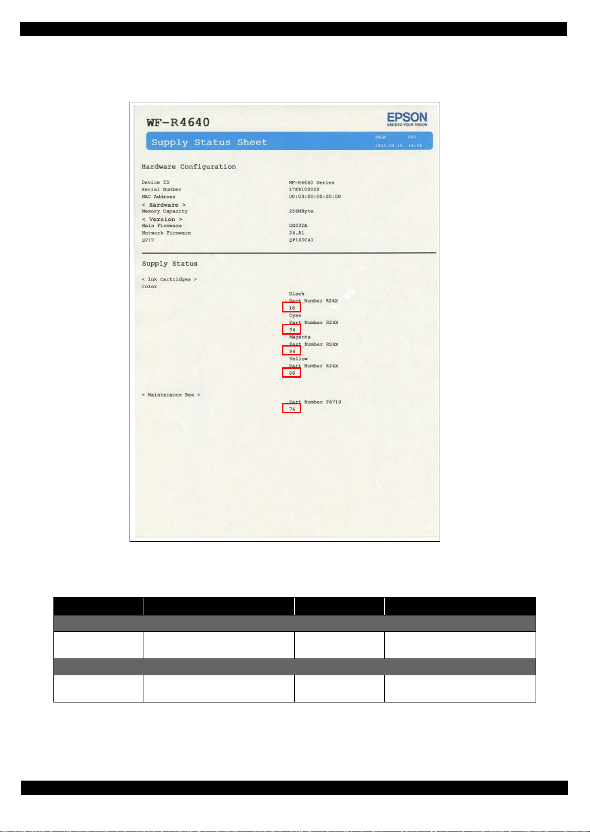
Epson WF-R5690/R4640/R5190 series Revision B
1.1.5.2 Description of Status sheet (Non-disclosed information to user)
Supply Status sheet
Figure 1-1. Supply Status Sheet (Non-disclosed information to user)
Item Content Item Content
Consumable information <Ink Cartridge>
Ink residual quantity Residual quantity information of the
Ink Cartridge. (each color)
Consumable information <Maintenance Box>
Maintenance Box
residual quantity
Residual quantity information of the
Maintenance Box.
Troubleshooting 29
Confidential
Page 30
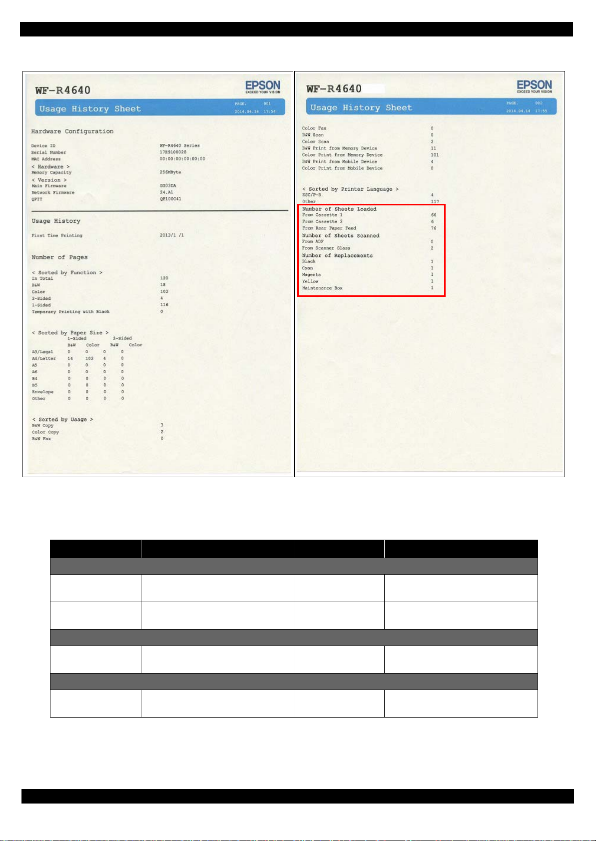
Epson WF-R5690/R4640/R5190 series Revision B
Usage History Sheet
Figure 1-2. Usage History Sheet (Non-disclosed information to user)
Item Content Item Content
Number of Sheets Loaded
Casette 1 Number of sheets loaded from 1st
cassette.
Rear Paper Feed Number of sheets loaded from rear
paper feed tray.
Number of Sheets Scanned
ADF Number of sheets scanned from ADF
Unit.
Number of Replacement
Ink Cartridge Number of replacement of Ink
cartridge
Cassette 2 Number of sheets loaded from 2nd
cassette.
Scanner Glass Number of sheets scanned from
Scanner Glass.
Maintenance Box Number of replacement of
Maintenance Box.
Troubleshooting 30
Confidential
Page 31

CHAPTER 2
DISASSEMBLY/REASSEMBLY
Confidential
Page 32

Epson WF-R5690/R4640/R5190 series Revision B
2.1 Overview
This chapter describes procedures for disassembling the main parts/units of WFR5690/R4640/R5190 series. Unless otherwise specified, disassembled parts/units can
be reassembled by reversing the disassembly procedure. See the cautions or tips for
disassembly/reassembly described in "2.3 Disassem bly and Assembly Procedure"
(Page 46).
Read the " Safety Precautions (p3)" before disassembling and reassembling.
2.1.1 Tools
Use only specified tools to avoid damaging the printer.
Name Availability
(+) Phillips screwdriver #1 O 1080530 JIS B1012-1985
(+) Phillips screwdriver #2 O --- JIS B1012-1985
Flathead screwdriver #3 O --- Qty.: two
Flathead Precision
screwdriver #1
(+) Stubby screwdriver O --- Total length 47 mm or less
Tweezers O --Longnose pliers O --Acetate tape --- 1003963
Teflon tape O --Rope O --Double-clip O --Magnetizer O --Hexagonal wrench key
(4mm)
O ---
O ---
EPSON
Part Code
Remarks
Note 1:Some of the tools listed above are commercially available.
2:EPSON provides the tools listed with EPSON part code.
DISASSEMBLY/REASSEMBLY Overview 32
Confidential
Page 33

Epson WF-R5690/R4640/R5190 series Revision B
2.1.2 Screw types used in the printer
The screw types used in the printer are shown in the table below. The screw types used
in each part/unit are indicated as the symbols below in the disassembly procedures with
the total number of used screws.
Symbol
1 C.B.P-TITE SCREW 3x10-F/ZN-3C 6 ± 1 Kgf·cm
2 C.B.S-TITE SCREW 3x6-F/ZN-3C 6 ± 1 Kgf·cm
3 C.B.P-TITE (P2) SCREW 3x10-F/ZN-3C 6 ± 1 Kgf
4 C.B.P-TITE SCREW 3x8-F/ZN-3C 6 ± 1 Kgf·cm
5 C.B.S-TITE (P4) SCREW 3x8-F/ZN-3C 6 ± 1 Kgf·cm
6 C.B.P-TITE SCREW 2.5x8-F/ZN-3C 6 ± 1 Kgf·cm
7 C.B.S-TITE (P4) SCREW 3x10-F/ZN-3C 6 ± 1 Kgf·cm
8 C.P.SCREW 3x4-F/ZN-3C 6 ± 1 Kgf·cm
9 C.B.EP-TITE SCREW 2.6x17 (B=14) F/ZN-3C 2.5 ± 0.4 Kgf
10 P.W.2.8x0.5x6.5-F/ZN-3C 3 ± 0.5 Kgf·cm
11 C.P.SECREW 2.5x6-F/ZN-3C 6 ± 1 Kgf·cm
12 C.B.P-TITE SCREW 3x14-F/ZN-3C 6 ± 1 Kgf·cm
13 C.B.S-TITE (P2) SCREW 3x8-F/ZB-3C 8 ± 1 Kgf
14 C.B.S-TITE SCREW 3x6-F/ZN-3C 8 ± 1 Kgf·cm
15 C.B.S-TITE SCREW 3x8-F/ZN-3C 6 ± 1 Kgf·cm
16 C.B.S-TITE SCREW 3x10-F/ZN-3C 6 ± 1 Kgf·m
17 C.B.S-TITE SCREW 2.5x4-F/Z-3C 3 ± 0.5 Kgf·cm
18 C.B.S-TITE (P2) SCREW 3x8-F/Z-3C 6 ± 1 Kgf·cm
19 C.B.S-TITE-SCREW 3x8 F/ZN-3C 6 ± 0.5 Kgf
Screw Type Torque
·cm
·cm
·cm
·cm
2.1.3 Standard Operation Time for servicing the product
The following are the standard operation time for servicing the product. The underlined
parts/units are supplied as After Service Parts.
WF-R5690/R4640 series
Time
Parts/Unit
Panel Unit
ADF Pad Assy 0:10 --- 0:10
Duplex Unit 0:02 7:50 7:52
Maintenance Box 0:04 --- 0:04
Hosing Rear Assy 0:49 --- 0:49
Housing Rear 1:04 --- 1:04
Paper Support 1:04 --- 1:04
Paper Cassette (1st) 0:02 1:02 1:04
Paper Cassette (2nd) 0:02 1:02 1:04
Cover Hinge (BK) 0:53 --- 0:53
Switch Cover (BK) 0:21 --- 0:21
Ink Supply BK Cover Open Sensor 0:38 --- 0:38
Ink Supply BK Cover
Inner Cover (BK) 2:25 --- 2:25
Ink Pack Holder Slider Assy (BK) 5:33 --- 5:33
Ink Supply Needle (BK) 5:42 --- 5:42
Tube Holder (BK) 5:42 --- 5:42
Extension Spring 2.47 (BK) 5:44 --- 5:44
(BK) 5:55 10:00 15:55
Tube
IS BK Base Assy 8:28 --- 8:28
Tube Cover Front 0:34 --- 0:34
Cover Hinge (CL) 0:55 --- 0:55
Switch Cover (CL) 0:21 --- 0:21
Assy 1:54 --- 1:54
Replacement
Adjustment/
Inspection
1:00 0:25 1:25
Total
DISASSEMBLY/REASSEMBLY Overview 33
Confidential
Page 34

Epson WF-R5690/R4640/R5190 series Revision B
Time
Parts/Unit
Ink Supply CL Cover Open Sensor 0:38 --- 0:38
Ink Supply CL Cover Assy 2:06 --- 2:06
Inner Cover CL 3:05 --- 3:05
Ink Pack Holder Slider Assy (YE) 5:14 --- 5:14
Ink Supply Needle (YE) 5:23 --- 5:23
Tube Holder (YE) 5:23 --- 5:23
Extension Spring 2.47 (YE) 5:25 --- 5:25
Ink Pack Holder Slider Assy (MA) 5:27 --- 5:27
Ink Supply Needle (MA) 5:36 --- 5:36
Tube Holder (MA) 5:36 --- 5:36
Extension Spring 2.47 (MA) 5:38 --- 5:38
Ink Pack Holder Slider Assy
Ink Supply Needle (CY) 5:36 --- 5:36
Tube Holder (CY) 5:36 --- 5:36
Extension Spring 2.47 (CY) 5:38 --- 5:38
IS Relay Board (CL) 4:29 --- 4:29
IS Base CL Assy 15:40 --- 15:40
Bottom Housing Assy 1:50 --- 1:50
2nd Cassette Housing 1:50 --- 1:50
2nd Cassette Cover Left 2:50 --- 2:50
2nd Cassette Cover Right 2:55 --- 2:55
2nd Cassette Cover Front 2:14 --- 2:14
2nd Paper Support Assy 2:19 --- 2:19
2nd Cassette Housing Assy 4:19 --- 4:19
Frame Pick Up Assy 8:57 --- 8:57
Pick Up
Metal Plate (w Paper Support Assy) 3:10 --- 3:10
Pick Up Assy 1st 3:23 --- 3:23
Assy 2nd 9:09 --- 9:09
(CY) 5:27 --- 5:27
Replacement
Adjustment/
Inspection
Total
Time
Parts/Unit
Paper Support Assy 2:21 --- 2:21
Stacker & Holder 1:26 --- 1:26
USB Cover 11:37 --- 11:37
ADF/SCN Unit 14:30 2:15 16:45
ADF Unit 19:11 2:15 21:26
Rear Cover 19:44 --- 19:44
ADF
ADF Cover Assy 19:57 --- 19:57
ADF Cover Housing Upper 21:06 --- 21:06
LD Cover 21:22 --- 21:22
LD Shaft 21:26 --- 21:26
Extension Spring 21:54 --- 21:54
ADF LD Assy
ADF Document Support 19:54 --- 19:54
Scanner Unit
Housing Front Assy 15:50 --- 15:50
Sensor Cover 16:12 --- 16:12
Housing Front Cover Open Sensor 16:17 --- 16:17
Housing Front 16:17 --- 16:17
Stacker Assy 16:02 --- 16:02
Middle Housing Assy 17:30 --- 17:30
Middle Housing 19:14 --- 19:14
Bracket 19:14 --- 19:14
Main Board Assy 23:28 17:05 40:33
Main Board Cable Holder 23:40 --- 23:40
Main Board Holder 24:03 --- 24:03
Main Board Shield Plate Assy 27:00 --- 27:00
Interface Board Assy 27:57 --- 27:57
Interface Board Shield Plate Upper 28:27 --- 28:27
Replacement
Adjustment/
Inspection
22:39 --- 22:39
19:11 2:15 21:26
Total
DISASSEMBLY/REASSEMBLY Overview 34
Confidential
Page 35

Epson WF-R5690/R4640/R5190 series Revision B
Time
Parts/Unit
Interface Board 28:44 --- 28:44
Interface Board Shield Plate Lower 28:44 --- 28:44
Main Board Shield Plate 27:57 --- 27:57
Main Board (Read OK) 28:13 1:59 30:12
Main Board (Read NG) 28:13 17:05 45:18
Main Board Shield Plate Lower 28:13 --- 28:13
Rear ASF Assy 18:44 2:14 20:58
Rear ASF Guide Upper 19:21 --- 19:21
Main Frame Assembly 19:46 --- 19:46
Decompress Pump Unit 20:13 --- 20:13
Power Supply Unit 20:59 3:07 24:06
PF Shield Plate 18:33 --- 18:33
PF Encoder 18:47 --- 18:47
Encoder FFC 19:15 --- 19:15
PF
PF Tension Stopper Holder 19:04 0:15 19:19
PF Timing Belt 19:19 0:15 19:34
Support Plate Right/ Support Plate Left 18:26 4:10 22:36
CR Cover 17:44 --- 17:44
Ink System 27:34 33:15 60:49
Printhead
Head FFC 21:33 --- 21:33
Ink Supply Unit 26:59 19:08 46:7
Fasten Plate Center 32:05 --- 32:05
Fasten Plate Left 33:41 --- 33:41
Driven Pulley Assy 34:23 --- 34:23
CR Motor 41:10 0:30 41:40
SUB Board 19:32 --- 19:32
CR Contact Module 18:50 --- 18:50
Replacement
Adjustment/
Inspection
20:59 42:23 63:22
Total
Time
Parts/Unit
PE Board Assy 18:22 --- 18:22
Wireless LAN Module 17:30 --- 17:30
Maintenance Box Ink Eject Joint 24:16 --- 24:16
Ink System Assy 24:42 --- 24:42
ASF Drive Change lever Assy 25:20 --- 25:20
Option Connector
CR Scale 34:42 --- 34:42
Star Wheel Assy 34:37 1:39 36:16
EJ Roller 36:49 2:58 39:47
Front Frame Assy 37:29 10:13 47:42
Upper Cover Tube Assy 37:56 --- 37:56
Lower Cover Tube Assy 38:24 --- 38:24
Tube (Y) 40:35 10:00 50:35
(M) 40:48 10:00 50:48
Tube
Tube (C) 40:48 10:00 50:48
CR Guide Frame Assy (w/ Carriage Assy) 47:44 23:31 71:15
CR Guide Frame 47:52 23:12 71:04
Carriage Assy 47:52 23:31 71:23
Replacement
Adjustment/
Inspection
25:44 --- 25:44
Total
DISASSEMBLY/REASSEMBLY Overview 35
Confidential
Page 36

Epson WF-R5690/R4640/R5190 series Revision B
WF-R5190 series
Time
Parts/Unit
Panel Unit
Duplex Unit 0:02 7:50 7:52
Maintenance Box 0:04 --- 0:04
Hosing Rear Assy 0:49 --- 0:49
Housing Rear
Paper Support 1:04 --- 1:04
Paper Cassette (1st) 0:02 1:02 1:04
Paper Cassette (2nd) 0:02 1:02 1:04
Cover Hinge (BK) 0:53 --- 0:53
Switch Cover (BK) 0:21 --- 0:21
Ink Supply BK Cover Open Sensor
Ink Supply BK Cover Assy 1:54 --- 1:54
Inner Cover (BK) 2:25 --- 2:25
Ink Pack Holder Slider Assy (BK) 5:33 --- 5:33
Ink Supply Needle (BK) 5:42 --- 5:42
Tube Holder (BK) 5:42 --- 5:42
Extension Spring 2.47 (BK) 5:44 --- 5:44
Tube (BK) 5:55 10:00 15:55
IS BK Base Assy 8:28 --- 8:28
Tube Cover Front 0:34 --- 0:34
Cover Hinge (CL) 0:55 --- 0:55
Switch Cover (CL) 0:21 --- 0:21
Ink Supply CL Cover Open Sensor 0:38 --- 0:38
Ink Supply CL Cover Assy 2:06 --- 2:06
Inner Cover
Ink Pack Holder Slider Assy (YE) 5:14 --- 5:14
Ink Supply Needle (YE) 5:23 --- 5:23
CL 3:05 --- 3:05
Replacement
Adjustment/
Inspection
0:19 --- 0:19
1:04 --- 1:04
0:38 --- 0:38
Total
Time
Parts/Unit
Tube Holder (YE) 5:23 --- 5:23
Extension Spring 2.47 (YE) 5:25 --- 5:25
Ink Pack Holder Slider Assy (MA) 5:27 --- 5:27
Ink Supply Needle (MA) 5:36 --- 5:36
Tube Holder (MA) 5:36 --- 5:36
Extension Spring 2.47 (MA) 5:38 --- 5:38
Ink Pack Holder Slider Assy (CY) 5:27 --- 5:27
Ink Supply Needle (CY) 5:36 --- 5:36
Tube Holder (CY) 5:36 --- 5:36
Extension Spring 2.47 (CY) 5:38 --- 5:38
IS Relay Board (CL) 4:29 --- 4:29
IS Base CL Assy 15:40 --- 15:40
Bottom Housing Assy 1:50 --- 1:50
2nd Cassette Housing 1:50 --- 1:50
2nd Cassette Cover Left 2:50 --- 2:50
2nd Cassette Cover Right 2:55 --- 2:55
2nd Cassette Cover Front 2:14 --- 2:14
2nd Paper Support Assy 2:19 --- 2:19
2nd Cassette Housing Assy 4:19 --- 4:19
Frame Pick Up Assy 8:57 --- 8:57
Pick Up Assy 2nd 9:09 --- 9:09
Metal Plate (w Paper Support Assy) 3:10 --- 3:10
Pick Up Assy 1st 3:23 --- 3:23
Paper Support Assy 2:21 --- 2:21
Housing Upper 1:37 --- 1:37
Cover 12:14 --- 12:14
USB
Housing Front Assy 12:13 --- 12:13
Sensor Cover 12:35 --- 12:35
Replacement
Adjustment/
Inspection
Total
DISASSEMBLY/REASSEMBLY Overview 36
Confidential
Page 37

Epson WF-R5690/R4640/R5190 series Revision B
Time
Parts/Unit
Housing Front Cover Open Sensor 12:40 --- 12:40
Housing Front 12:40 --- 12:40
Stacker Assy 12:25 --- 12:25
Middle Housing Assy 15:14 --- 15:14
Middle Housing 16:58 --- 16:58
Bracket
Main Board Assy 21:12 17:05 38:17
Main Board Cable Holder 21:24 --- 21:24
Main Board Holder 21:47 --- 21:47
Main Board Shield Plate Assy 25:01 --- 25:01
Main Board (Read OK) 25:45 1:59 27:44
Main Board (Read NG)
Main Board Shield Plate Lower 25:45 --- 25:45
ASF Assy 16:28 2:14 18:42
Rear
Rear ASF Guide Upper 17:05 --- 17:05
Main Frame Assembly 17:30 --- 17:30
Decompress Pump Unit 17:57 --- 17:57
Power Supply Unit 18:43 3:07 21:50
PF Shield Plate 16:17 --- 16:17
Encoder 16:31 --- 16:31
PF
PF Encoder FFC 16:59 --- 16:59
PF Tension Stopper Holder 16:48 0:15 17:03
PF Timing Belt 17:03 0:15 17:18
Support Plate Right/ Support Plate Left 16:10 4:10 20:20
CR Cover 15:28 --- 15:28
Ink System
Printhead 18:43 42:23 61:06
Head FFC 19:17 --- 19:17
Replacement
Adjustment/
Inspection
16:58 --- 16:58
25:45 17:05 42:50
25:18 33:15 58:33
Total
Time
Parts/Unit
Ink Supply Unit 24:43 19:08 43:51
Fasten Plate Center 29:49 --- 29:49
Fasten Plate Left 31:25 --- 31:25
Driven Pulley Assy 32:07 --- 32:07
CR Motor 38:54 0:30 39:24
Board 17:16 --- 17:16
SUB
CR Contact Module 16:34 --- 16:34
PE Board Assy 16:06 --- 16:06
Wireless LAN Module 16:00 --- 16:00
Maintenance Box Ink Eject Joint 22:00 --- 22:00
Ink System Assy 22:26 --- 22:26
ASF Drive Change lever Assy 23:04 --- 23:04
Option Connector 24:42 --- 24:42
Scale 32:26 --- 32:26
CR
Star Wheel Assy 32:21 1:39 34:00
EJ Roller 34:33 2:58 37:31
Front Frame Assy 35:13 10:13 45:26
Upper Cover Tube Assy 35:40 --- 35:40
Lower Cover Tube Assy 36:08 --- 36:08
(Y) 38:19 10:00 48:19
Tube
Tube (M) 38:32 10:00 48:32
Tube (C) 38:32 10:00 48:32
CR Guide Frame Assy (w/ Carriage Assy) 38:18 23:31 61:49
CR Guide Frame 38:18 23:12 61:30
Carriage Assy 38:18 23:31 61:49
Replacement
Adjustment/
Inspection
Total
DISASSEMBLY/REASSEMBLY Overview 37
Confidential
Page 38

Epson WF-R5690/R4640/R5190 series Revision B
A
A
A
A
A
A
A
A
A
A
H
I
G
J
A
B
C
F
D
E
2.2 Parts Diagram
No. Part/ Unit name No. Part/ Unit name No. Part/ Unit name No. Part/ Unit name
ADF/Scanner Unit (p.53)
A
Panel Unit (p.48)
B
Middle Housing (p.57)
C
Cassette Assy (p.47)
D
Front Housing Assy (p.55)
E
Speaker (p.50)
F
Housing Rear Assy (p.51)
G
Duplex Unit (p.47)
H
Maintenance Box (p.47)
I
FAX Cover (p.52)
J
Figure 2-1. Housing (WF-R5690/R4640 series)
DISASSEMBLY/REASSEMBLY Parts Diagram 38
Confidential
Page 39

Epson WF-R5690/R4640/R5190 series Revision B
A
A
A
A
A
A
A
A
B
C
D
E
I
A
H
A
G
F
No. Part/ Unit name No. Part/ Unit name No. Part/ Unit name No. Part/ Unit name
Housing Upper (p.61)
A
Panel Unit (p.59)
B
Middle Housing (p.67)
C
Cassette Assy (p.47)
D
Front Housing Assy (p.65)
E
Housing Rear Assy (p.63)
F
Duplex Unit (p.47)
G
Maintenance Box (p.47)
H
USB Cover (p.64)
I
Figure 2-2. Housing (WF-R5190 series)
DISASSEMBLY/REASSEMBLY Parts Diagram 39
Confidential
Page 40

Epson WF-R5690/R4640/R5190 series Revision B
A
N
A
M
A
L
A
O
A
G
A
H
A
A
I
J
A
A
A
A
A
A
A
B
C
D
E
F
A
K
No. Part/ Unit name No. Part/ Unit name No. Part/ Unit name No. Part/ Unit name
Ink Supply Unit (p.90)
A
EJ Roller (p.118)
B
Printhead (p.85)
C
CR Guide Frame Assy (p.109)
D
Rear ASF Guide Upper (p.79)
E
CR Scale (p.104)
F
Ink System (p.106)
G
Head FFC (p.96)
H
Front Frame Assy (p.115)
I
Star Wheel Assy (p.114)
J
PF Encoder (p.83)
K
Main Board Unit (p.69)/
L
Main Board (p.74)
Decompress Pump Unit (p.81)
M
Power Supply Unit (p.76)
N
Rear ASF Assy (p.77)
O
Figure 2-3. Printer Mechanism (1)
DISASSEMBLY/REASSEMBLY Parts Diagram 40
Confidential
Page 41

Epson WF-R5690/R4640/R5190 series Revision B
A
A
No. Part/ Unit name No. Part/ Unit name No. Part/ Unit name No. Part/ Unit name
Frame Base Assy (p.113)
A
Figure 2-4. Printer Mechanism (2)
DISASSEMBLY/REASSEMBLY Parts Diagram 41
Confidential
Page 42

Epson WF-R5690/R4640/R5190 series Revision B
A
A
A
C
D
E
A
F
A
B
A
A
No. Part/ Unit name No. Part/ Unit name No. Part/ Unit name No. Part/ Unit name
Ink Supply BK Cover Open Sensor
A
(p.131)
Ink Supply BK Assy (p.134)
B
Ink Supply BK Cover Open Sensor
C
(p.131)
Ink tube (p.144)
D
Ink Supply Needle (p.144)
E
Ink Pack Holder (BK) (p.140)
F
Figure 2-5. RIPS Unit (1)
DISASSEMBLY/REASSEMBLY Parts Diagram 42
Confidential
Page 43

Epson WF-R5690/R4640/R5190 series Revision B
A
A
A
A
A
A
A
A
A
A
A
A
D
C
D
D
D
E
E
F
F
F
E
A
B
No. Part/ Unit name No. Part/ Unit name No. Part/ Unit name No. Part/ Unit name
Ink Supply BK Cover Open Sensor
A
(p.131)
Ink Supply CL Assy (p.136)
B
Ink Supply CL Cover Open Sensor
C
(p.132)
Ink Pack Holder (Y/M/C) (p.142)
D
Ink Supply Needle (p.144)
E
Ink tube (p.144)
F
Figure 2-6. RIPS Unit (2)
DISASSEMBLY/REASSEMBLY Parts Diagram 43
Confidential
Page 44

Epson WF-R5690/R4640/R5190 series Revision B
A
A
A
A
A
A
D
C
E
B
No. Part/ Unit name No. Part/ Unit name No. Part/ Unit name No. Part/ Unit name
ADF Rear Cover (p.146)
A
ADF Cover Assy (p.147)
B
ADF LD Assy (p.148)
C
ADF Document Support Assy (p.147)
D
Scanner Unit (p.149)
E
Figure 2-7. ADF/SCN Unit
DISASSEMBLY/REASSEMBLY Parts Diagram 44
Confidential
Page 45

Epson WF-R5690/R4640/R5190 series Revision B
A
A
A
B
A
C
No. Part/ Unit name No. Part/ Unit name No. Part/ Unit name No. Part/ Unit name
Pick Up Roller Assy 1st (p.156)
A
2nd Cassette Unit (p.152)
B
Paper Stopper Assy 1st/2nd (p.154)
C
Figure 2-8. 2nd Cassette Unit
DISASSEMBLY/REASSEMBLY Parts Diagram 45
Confidential
Page 46

Epson WF-R5690/R4640/R5190 series Revision B
Left
Gear
CR unlocked
(The Lever is lowered)
CR Lock Lever
CR locked
(The lever is raised)
2.3 Disassembly and Assembly Procedure
2.3.1 Preparation for servicing
2.3.1.1 Unlocking the Carriage Assy
1. Remove the Middle Housing.
(WF-R5690/R4640 series (P.57), WF-R5190 series (P.67))
2. Remove the Metal Plate Left. (P.83)
3. Rotate the gear in the direction of the arrow to unlock the Carriage Assy.
Figure 2-10. Status of the CR Lock Lever
Figure 2-9. Unlocking the Carriage Assy
DISASSEMBLY/REASSEMBLY Disassembly and Assembly Procedure 46
Confidential
Page 47

Epson WF-R5690/R4640/R5190 series Revision B
Ink Pack
Duplex Unit
Maintenance Box
Cassette Assy
2.3.1.2 Parts/Units Need to be Removed in Advance
Make sure to remove the following parts/units before starting disassembly.
2.3.1.2.1 Ink Pack
Figure 2-11. Removing the Ink Pack
2.3.1.2.2 Duplex Unit
2.3.1.2.3 Maintenance Box
Figure 2-13. Removing the Maintenance Box
2.3.1.2.4 Cassette Assy
Figure 2-14. Removing the Cassette Assy 1st
Figure 2-12. Removing the Duplex Unit
DISASSEMBLY/REASSEMBLY Disassembly and Assembly Procedure 47
Confidential
Page 48

Epson WF-R5690/R4640/R5190 series Revision B
Hook
Bottom right of
ADF/Scanner Unit
Hook
Bottom left of
ADF/Scanner Unit
ADF/Scanner Unit
Front Cover
2.3.2 Exterior parts (WF-R5690/R4640 series)
2.3.2.1 Panel Unit
1. Open the Front Cover.
2. Release the two hooks on the back of the Panel Unit from the bottom of the ADF/
Scanner Unit, and disengage the Panel Unit.
DISASSEMBLY/REASSEMBLY Disassembly and Assembly Procedure 48
For the screw types, see "2.1.2 Screw types used in the printer (p33)".
Do not lift the Panel Unit too fast, since the Panel FFC and th e
Speaker cable are connected to it.
Figure 2-15. Removing the Panel Unit (1)
Confidential
Page 49

Epson WF-R5690/R4640/R5190 series Revision B
Speaker cable
FFC
Panel Unit
Hook
Tab
ADF/Scanner Unit
Tabs
Tabs
Hooks
Hooks
FFC
Main Board
Main Board
Grounding wire
S2
3. Disconnect the Speaker cable and the FFC from the connectors on the Panel Unit.
Figure 2-16. Removing the Panel Unit (2)
Attach the Panel Unit in the following order.
1. Insert the five tabs into the five holes on the ADF/Scanner Unit.
2. Secure the Panel Unit with the five hooks.
3. Disconnect the Panel FFC from the Main Board, and remove the Panel FFC from
Scanner Unit.
Figure 2-17. Removing the Panel Unit (3)
4. Remove the screw (S2) that secures the grounding wire to release the wire, and
remove the Panel Unit.
DISASSEMBLY/REASSEMBLY Disassembly and Assembly Procedure 49
Figure 2-18. Removing the Panel Unit (4)
Carry out the adjustments referring to "3.1 Required
Adjustments" (p185) after replacing the Panel Unit.
Confidential
Page 50

Epson WF-R5690/R4640/R5190 series Revision B
Speaker Holder
Speaker
2.3.2.2 Speaker
For the screw types, see "2.1.2 Screw types used in the printer (p33)".
1. Remove the Panel Unit. (P.48)
2. Turn the Speaker Holder in the direction of the arrows, and remove the Speaker.
Figure 2-19. Removing the Speaker
Route the Speaker cable referring to "2.4 Routing FFCs/Cables"
(Page 160).
DISASSEMBLY/REASSEMBLY Disassembly and Assembly Procedure 50
Confidential
Page 51

Epson WF-R5690/R4640/R5190 series Revision B
Rear left
S1
Rear right
S1
Housing Rear Assy
2.3.2.3 Housing Rear Assy
For the screw types, see "2.1.2 Screw types used in the printer (p33)".
1. Remove the four screws (S1), and remove the Housing Rear Assy.
Figure 2-20. Removing the Housing Rear Assy
DISASSEMBLY/REASSEMBLY Disassembly and Assembly Procedure 51
Confidential
Page 52

Epson WF-R5690/R4640/R5190 series Revision B
S1
FAX Cover
2.3.2.4 FAX Cover
For the screw types, see "2.1.2 Screw types used in the printer (p33)".
1. Remove the Housing Rear Assy. (P.51)
2. Slide the Ink Supply BK Assy to release it. (P.125)
3. Slide the Ink Supply CL Assy to release it. (P.128)
4. Remove the two screws (S1), and remove the FAX Cover.
Figure 2-21. Removing the FAX Cover
DISASSEMBLY/REASSEMBLY Disassembly and Assembly Procedure 52
Confidential
Page 53

Epson WF-R5690/R4640/R5190 series Revision B
Rear left
S1
Rear right
S1
S1
2.3.2.5 ADF/Scanner Unit
For the screw types, see "2.1.2 Screw types used in the printer (p33)".
1. Remove the Panel Unit. (P.48)
2. Remove the Speaker. (P.50)
3. Remove the Housing Rear Assy. (P.51)
4. Slide the Ink Supply BK Assy to release it. (P.125)
7. Remove the five screws (S1).
5. Slide the Ink Supply CL Assy to release it. (P.128)
6. Remove the FAX cover. (P.52)
DISASSEMBLY/REASSEMBLY Disassembly and Assembly Procedure 53
Figure 2-22. Removing the ADF/Scanner Unit (1)
Confidential
Page 54

Epson WF-R5690/R4640/R5190 series Revision B
Main Board
FFC
Cables
Grounding wire
S2
Cable
FFC
Main Board
ADF/Scanner Unit
8. Disconnect the FFC from the connector on the Main Board.
Figure 2-23. Removing the ADF/Scanner Unit (2)
9. Remove the screw (S2) that secures the grounding wire to release the wire.
10. Disconnect the cables from the four connectors on the Main Board.
11. Lift the ADF/Scanner Unit and disconnect the FFC and cable from the connectors
on the Main Board.
Figure 2-25. Removing the ADF/Scanner Unit (4)
12. Remove th e ADF/Scanner Unit upward.
Route the cable referring to "2.4 Routing FFCs/Cables" (Page
160).
Carry out the adjustments referring to "3.1 Required
Adjustments" (p185) after replacing the ADF/Scanner Unit.
Figure 2-24. Removing the ADF/Scanner Unit (3)
DISASSEMBLY/REASSEMBLY Disassembly and Assembly Procedure 54
Confidential
Page 55

Epson WF-R5690/R4640/R5190 series Revision B
Cover Tube Front
Front Cover
S12
S12
S12
Connector (CN20)
Cable
Main Board
2.3.2.6 Front Housing Assy
For the screw types, see "2.1.2 Screw types used in the printer (p33)".
1. Remove the Panel Unit. (P.48)
2. Remove the Housing Rear Assy. (P.51)
3. Slide the Ink Supply BK Assy to release it. (P.125)
4. Slide the Ink Supply CL Assy to release it. (P.128)
7. Open the Front Cover.
8. Remove the two screws (S12).
9. Remove the Cover Tube Front.
10. Remove the screw (S12).
Figure 2-26. Removing the Cover Tube Front
11. Disconnect the cable from the connector (CN20) on the Main Board.
5. Remove the FAX cover. (P.52)
6. Remove the ADF/Scanner Unit. (P.53)
Figure 2-27. Removing the Front Housing Assy (1)
DISASSEMBLY/REASSEMBLY Disassembly and Assembly Procedure 55
Confidential
Page 56

Epson WF-R5690/R4640/R5190 series Revision B
Hook B
Hook B
Hook B
Front Housing
Assy
Cutout
Hook A
Hook A
Cutout
12. Insert the flat-head screwdriver into the cutout on the Housing Lower, and release the hook A.
13. Release the hook B on the Front Housing Assy, and remove the Front Housing Assy toward you.
DISASSEMBLY/REASSEMBLY Disassembly and Assembly Procedure 56
Figure 2-28. Removing the Front Housing Assy (2)
Confidential
Page 57

Epson WF-R5690/R4640/R5190 series Revision B
Rear
Front
S1
S1
S1
S1
2.3.2.7 Middle Housing
For the screw types, see "2.1.2 Screw types used in the printer (p33)".
1. Remove the Panel Unit. (P.48)
2. Remove the Housing Rear Assy. (P.51)
3. Slide the Ink Supply BK Assy to release it. (P.125)
4. Slide the Ink Supply CL Assy to release it. (P.128)
8. Remove the four screws (S1).
5. Remove the FAX cover. (P.52)
6. Remove the ADF/Scanner Unit. (P.53)
7. Remove the Front Housing Assy. (P.55)
Figure 2-29. Removing the Middle Housing (1)
DISASSEMBLY/REASSEMBLY Disassembly and Assembly Procedure 57
Confidential
Page 58

Epson WF-R5690/R4640/R5190 series Revision B
Cutout
Ink Supply BK Assy
FFC, Cable, Tube
Ink Supply BK Assy
Middle Housing
9. Release the FFC, cable, and ink tube of the Ink Supply BK Assy from the cutout
on the Middle Housing.
Figure 2-30. Removing the Middle Housing (2)
10. Move the Ink Supply BK Assy to th e front of the prin ter.
When moving the Ink Supply BK Assy, take care not to damage the
FFC, cable or the tube.
11. Remove th e Middle Housing upward.
DISASSEMBLY/REASSEMBLY Disassembly and Assembly Procedure 58
Figure 2-31. Removing the Middle Housing (3)
Confidential
Page 59

Epson WF-R5690/R4640/R5190 series Revision B
Hook
Bottom of Housing Upper Assy
2.3.3 Exterior parts (WF-R5190 series)
2.3.3.1 Panel Unit
For the screw types, see "2.1.2 Screw types used in the printer (p33)".
1. While releasing the hook on the back of the Panel Unit from the bottom of the
Housing Upper Assy, disengage the left side of the Panel Unit.
DISASSEMBLY/REASSEMBLY Disassembly and Assembly Procedure 59
Figure 2-32. Removing the Panel Unit (1)
Confidential
Page 60

Epson WF-R5690/R4640/R5190 series Revision B
Front Cover
Two
hooks
FFC
Panel Unit
Hook A
Rear side of Panel Unit
Hook A
Hook A
Hook B
2. Slightly slide the Panel Unit in the direction of the arrow to release the two hooks,
and disengage the Panel Unit.
Figure 2-33. Removing the Panel Unit (2)
3. Disconnect the FFC from the connector on the Panel Unit.
4. Remove the Panel Unit from the Housing Upper.
Figure 2-34. Removing the Panel Unit (3)
Insert the ribs into the holes on the Housing Upper in the order of
the hook A and hook B.
DISASSEMBLY/REASSEMBLY Disassembly and Assembly Procedure 60
Confidential
Page 61

Epson WF-R5690/R4640/R5190 series Revision B
Rear right
S1
Rear left
S1
S1
2.3.3.2 Housing Upper
For the screw types, see "2.1.2 Screw types used in the printer (p33)".
2. Remove the five screws (S1).
1. Remove the Panel Unit. (P.59)
DISASSEMBLY/REASSEMBLY Disassembly and Assembly Procedure 61
Figure 2-35. Removing the Housing Upper (1)
Confidential
Page 62

Epson WF-R5690/R4640/R5190 series Revision B
FFC
Main Board
Housing Upper
3. Lift the Housing Upper.
4. Disconnect the FFC from the connector on the Main Board, and remove the
Housing Upper.
Figure 2-36. Removing the Housing Upper (2)
DISASSEMBLY/REASSEMBLY Disassembly and Assembly Procedure 62
Confidential
Page 63

Epson WF-R5690/R4640/R5190 series Revision B
Rear right
S1
Rear left
S1
Housing
Rear Assy
2.3.3.3 Housing Rear Assy
For the screw types, see "2.1.2 Screw types used in the printer (p33)".
1. Remove the four screws (S1), and remove the Housing Rear Assy.
Figure 2-37. Removing the Housing Rear Assy
DISASSEMBLY/REASSEMBLY Disassembly and Assembly Procedure 63
Confidential
Page 64

Epson WF-R5690/R4640/R5190 series Revision B
S1
USB Cover
2.3.3.4 USB Cover
For the screw types, see "2.1.2 Screw types used in the printer (p33)".
1. Remove the Panel Unit. (P.59)
2. Remove the Housing Upper. (P.61)
6. Remove the two screws (S1), and remove the USB Cover.
Figure 2-38. Removing the USB cover
3. Remove the Housing Rear Assy. (P.63)
4. Slide the Ink Supply BK Assy to release it. (P.125)
5. Slide the Ink Supply CL Assy to release it. (P.128)
DISASSEMBLY/REASSEMBLY Disassembly and Assembly Procedure 64
Confidential
Page 65

Epson WF-R5690/R4640/R5190 series Revision B
Cover Tube Front
Front Cover
S12
S12
S12
Connector (CN20)
Cable
Main Board
2.3.3.5 Front Housing Assy
For the screw types, see "2.1.2 Screw types used in the printer (p33)".
1. Remove the Panel Unit. (P.59)
2. Remove the Housing Upper. (P.61)
3. Slide the Ink Supply BK Assy to release it. (P.125)
4. Slide the Ink Supply CL Assy to release it. (P.128)
5. Open the Front Cover.
6. Remove the two screws (S12).
7. Remove the Cover Tube Front.
8. Remove the screw (S12).
Figure 2-39. Removing the Cover Tube Front
9. Disconnect the cable from the connector (CN20) on the Main Board.
Figure 2-40. Removing the Front Housing Assy (1)
DISASSEMBLY/REASSEMBLY Disassembly and Assembly Procedure 65
Confidential
Page 66

Epson WF-R5690/R4640/R5190 series Revision B
Hook B
Hook B
Hook B
Front Housing
Assy
Cutout
Hook A
Hook A
Cutout
10. Insert the flat-head screwdriver into the cutout on the Housing Lower, and release the hook A.
11. Release the hook B on the Front Housing Assy, and remove the Front Housing Assy toward you.
DISASSEMBLY/REASSEMBLY Disassembly and Assembly Procedure 66
Figure 2-41. Removing the Front Housing Assy (2)
Confidential
Page 67

Epson WF-R5690/R4640/R5190 series Revision B
Rear
Front
S1
S1
S1
S1
2.3.3.6 Middle Housing
For the screw types, see "2.1.2 Screw types used in the printer (p33)".
1. Remove the Housing Rear Assy. (P.59)
2. Remove the Housing Upper. (P.61)
3. Remove the Housing Rear Assy. (P.63)
8. Remove the four screw (S1).
4. Slide the Ink Supply BK Assy to release it. (P.125)
5. Slide the Ink Supply CL Assy to release it. (P.128)
6. Remove the USB cover. (P.64)
7. Remove the Front Housing Assy. (P.65)
Figure 2-42. Removing the Middle Housing (1)
DISASSEMBLY/REASSEMBLY Disassembly and Assembly Procedure 67
Confidential
Page 68

Epson WF-R5690/R4640/R5190 series Revision B
Cutout
FFC, Cable, Tube
Ink Supply BK Assy
Middle Housing
9. Release the FFC, cables, and ink tube of the Ink Supply BK Assy from the cutout
on the Middle Housing.
Figure 2-43. Removing the Middle Housing (2)
10. Move the Ink Supply BK Assy to th e front of the prin ter.
When moving the Ink Supply BK Assy, take care not to damage the
FFC, cable or the tube.
11. Remove th e Middle Housing upward.
Figure 2-44. Removing the Middle Housing (3)
DISASSEMBLY/REASSEMBLY Disassembly and Assembly Procedure 68
Confidential
Page 69

Epson WF-R5690/R4640/R5190 series Revision B
Cutout
Ink Supply CL Assy
Tube (Y/M/C)
Tube (M/C)
2.3.4 Printer Mechanism
2.3.4.1 Main Board Unit
For the screw types, see "2.1.2 Screw types used in the printer (p33)".
1. Remove the Middle Housing.
(WF-R5690/R4640 series (P.57), WF-R5190 series (P.67))
4. Move the Ink Supply CL Assy to the front of the printer.
2. Release the Tubes (Y/M/C) from the Ink Supply CK Assy.
3. Move the Tubes (M/C) into the cutout on the Ink Supply CL Assy.
Figure 2-45. Moving the Ink Supply CL Assy
DISASSEMBLY/REASSEMBLY Disassembly and Assembly Procedure 69
Confidential
Page 70

Epson WF-R5690/R4640/R5190 series Revision B
Clamps
Clamps
Clamps
Main Board
FFC
FFC
FFC
Double-sided tape
Double-sided tape
Double-sided tape
5. Disconnect all the FFCs and cables from the Main Board Unit.
6. Release the cables from the seven clamps.
Figure 2-46. Removing the Main Board Unit (1)
7. Peel the three FFCs.
Figure 2-47. Removing the Main Board Unit (2)
DISASSEMBLY/REASSEMBLY Disassembly and Assembly Procedure 70
Confidential
Page 71

Epson WF-R5690/R4640/R5190 series Revision B
Hook
Cable
Acetate tape
Shield Plate Holder
Main Board Cable
Holder
Hook
Hook
8. Peel off the acetate tape.
9. Release the cable from the hook on the Shield Plate Holder.
Figure 2-48. Removing the Main Board Unit (3)
10. Release the two hooks on the Main Board Cable Holder, and detach the Main
Board Cable Holder.
Figure 2-49. Removing the Main Board Unit (4)
DISASSEMBLY/REASSEMBLY Disassembly and Assembly Procedure 71
Confidential
Page 72

Epson WF-R5690/R4640/R5190 series Revision B
Rib
Hook
Dowel
Dowel and
positioning hole
Main Board Cable
Holder
S2
Grounding wire
Main Board
Unit
S2
S2
11. Remove th e three screws (S2) that secure the grounding wire to release the wire.
Align the dowel on the Main Board Cable Holder with the
positioning hole on the frame.
12. Remove the Main Board Unit upward.
Figure 2-50. Removing the Main Board Unit (5)
DISASSEMBLY/REASSEMBLY Disassembly and Assembly Procedure 72
Confidential
Page 73

Epson WF-R5690/R4640/R5190 series Revision B
Rib
Rib
Main Board
Unit fixing plate
Main Board Unit
grounding plate
Main Frame
Grounding wire
When installing the Main Board Unit, insert the two ribs on the
Main Board Unit fixing plate into the two holes on the Main
Board Unit.
After installing the Main Board Unit, make sure that the leg on
the Main Board Unit grounding plate is in contact with the
Main Frame to ground itself.
Attach the terminal of the grounding cable in the direction
shown in figure below.
Route the cables and FFCs referring to "2.4 Routing FFCs/
Cables" (Page 160).
DISASSEMBLY/REASSEMBLY Disassembly and Assembly Procedure 73
Confidential
Page 74

Epson WF-R5690/R4640/R5190 series Revision B
Shield Plate Holder
S2
S2
Interface Board FFC
2.3.4.2 Main Board
For the screw types, see "2.1.2 Screw types used in the printer (p33)"
1. Remove the Middle Housing.
(WF-R5690/R4640 series (P.57), WF-R5190 series (P.67))
2. Remove the Main Board Unit. (P.69)
3. Remove the two screws (S2), and remove the Shield Plate Holder.
Figure 2-51. Removing the Shield Plate Holder
4. Disconnect the Interface Board FFC from the connector of the Main Board. (WFR5690/R4640 series only)
Figure 2-52. Removing the Interface Board FFC
DISASSEMBLY/REASSEMBLY Disassembly and Assembly Procedure 74
Confidential
Page 75

Epson WF-R5690/R4640/R5190 series Revision B
S2
S2
S2
S2
S2
S2
S11
S8
Main Board
Shield Plate
Upper Assy
Main Board Shield Plate
Lower Assy
2
1
3
S11
S2
S2
Main Board
5. Remove the nine screws (S2: 7 pcs, S8: 1 pcs, S11: 1 pcs), and remove the Main
Board Shield Plate Upper Assy.
6. Remove the three screws (S2: 2 pcs, S11: 1 pcs), and remove the Main Board from
the Main Board Shield Plate Lower Assy.
Figure 2-54. Removing the Main Board (2)
Tighten the screws in the order given in Figure 2-54.
Carry out the adjustments referring to "3.1 Required
Adjustments" (p185) after removing/replacing the Main Board.
Figure 2-53. Removing the Main Board (1)
DISASSEMBLY/REASSEMBLY Disassembly and Assembly Procedure 75
Confidential
Page 76

Epson WF-R5690/R4640/R5190 series Revision B
Frame
Cable
2.3.4.3 Power Supply Unit
For the screw types, see "2.1.2 Screw types used in the printer (p33)"
When removing the Power Supply Unit, take care not to damage
the Power Supply Unit cable with the edges of the frame.
1. Remove the Middle Housing.
(WF-R5690/R4640 series (P.57), WF-R5190 series (P.67))
2. Remove the Decompress Pump Unit. (P.81)
DISASSEMBLY/REASSEMBLY Disassembly and Assembly Procedure 76
Confidential
Page 77

Epson WF-R5690/R4640/R5190 series Revision B
Cable
Clamp
Connector
Power Supply Unit
S1
S2
3. Release the Power Supply Unit cable from the clamp.
4. Remove the two screws (S1: 1 pcs, S2: 1 pcs), and lift the Power Supply Unit.
5. Disconnect the Power Supply Unit cable from the connector, and remove the
Power Supply Unit.
2.3.4.4 Rear ASF Assy
For the screw types, see "2.1.2 Screw types used in the printer (p33)"
Figure 2-55. Removing the Power Supply Unit
Carry out the adjustments referring to "3.1 Required
Adjustments" (p185) after replacing the Power Supply Unit.
DISASSEMBLY/REASSEMBLY Disassembly and Assembly Procedure 77
Confidential
Page 78

Epson WF-R5690/R4640/R5190 series Revision B
Rear
S1
Dowel and
positioning hole
Frame Base Assy
Dowel and
positioning hole
Hook
Cable
S1
S1
Rear ASF Assy
Clutch Lever
Trigger Lever
1. Remove the Middle Housing.
(WF-R5690/R4640 series (P.57), WF-R5190 series (P.67))
2. Release the cable from the hook.
3. Remove the four screws (S1), and remove the Rear ASF Assy.
When installing the Rear ASF Assy to the Frame Base Assy,
move the Trigger Lever in the direction of the arrow to prevent
it from touching the Clutch Lever, and align the positioning
two holes of the Rear ASF Assy with the two dowels of the
Frame Base Assy.
Atta ch the two positioning holes of the Rear ASF Assy to the
two tabs of the Frame Base Assy. (
Route the cable referring to "2.4 Routing FFCs/Cables" (Page
160).
Carry out the adjustments referring to "3.1 Required
Adjustments" (p185) after replacing the Rear ASF Assy.
figure 2-56)
DISASSEMBLY/REASSEMBLY Disassembly and Assembly Procedure 78
Figure 2-56. Removing the Rear ASF Assy
Confidential
Page 79

Epson WF-R5690/R4640/R5190 series Revision B
Acetate tape
Cable
Hook
Hook
Hooks
S1
Rear ASF
Guide Upper
2.3.4.5 Rear ASF Guide Upper
For the screw types, see "2.1.2 Screw types used in the printer (p33)"
1. Remove the Middle Housing.
(WF-R5690/R4640 series (P.57), WF-R5190 series (P.67))
3. Peel off a two pieces of the acetate tape.
4. Release the cable from the three hooks on the Rear ASF Guide Upper.
5. Remove the screw (S1), and remove the Rear ASF Guide Upper.
Figure 2-57. Removing the Rear ASF Guide Upper
2. Remove the Rear ASF Assy. (P.77)
DISASSEMBLY/REASSEMBLY Disassembly and Assembly Procedure 79
Confidential
Page 80

Epson WF-R5690/R4640/R5190 series Revision B
Tabs
Holes of
Frame Driven Assy
Dowel and
positioning hole
Install the Rear ASF Guide Upper following step.
1. Insert the two ribs on the 80-digit side of the Rear ASF Guide
Upper Assy into the two holes of the Frame Driven Assy.
2. Align the positioning hole on the 0-digit side of the Rear ASF
Guide Upper Assy with the dowel of the Frame Base Assy, and
secure the Rear ASF Guide Upper Assy with the screw.
DISASSEMBLY/REASSEMBLY Disassembly and Assembly Procedure 80
Route the cable referring to "2.4 Routing FFCs/Cables" (Page
160).
Confidential
Page 81

Epson WF-R5690/R4640/R5190 series Revision B
Decompress Pump Tube
Ink Supply Unit
Joint
Hooks
2.3.4.6 Decompress Pump Unit
For the screw types, see "2.1.2 Screw types used in the printer (p33)"
1. Remove the Middle Housing.
(WF-R5690/R4640 series (P.57), WF-R5190 series (P.67))
2. Remove the Decompress Pump Tube from the joint of the Ink Supply Unit.
3. Release the Decompress Pump Tube from the three hooks on the frame.
Figure 2-58. Releasing the tube
DISASSEMBLY/REASSEMBLY Disassembly and Assembly Procedure 81
Confidential
Page 82

Epson WF-R5690/R4640/R5190 series Revision B
Connector(CN34)
Clamp
Hook
Cable
Hooks
Hooks
S3
S3
S1
S2
Decompress Pump Unit
4. Disconnect the cable from the connector (CN34) of the Main Board.
5. Release the cables from the five hooks of the frame and clamp.
Figure 2-59. Removing the Decompress Pump Unit (1)
6. Remove the four screws (S1: 1 pcs, S2: 1 pcs, S3: 2 pcs), and remove the
Decompress Pump Unit.
Figure 2-60. Removing the Decompress Pump Unit (2)
Route the Decompress Pump Tube through the three hooks of
the Ink Supply Unit, and insert the end of the tube into the joint
on the Ink Supply Unit to the full up to its base. (
Route the cable referring to "2.4 Routing FFCs/Cables" (Page
160).
figure 2-58)
DISASSEMBLY/REASSEMBLY Disassembly and Assembly Procedure 82
Confidential
Page 83

Epson WF-R5690/R4640/R5190 series Revision B
Metal Plate Left Sheet
Cable
S2
S2
Cutout
Metal Plate Left
Groove on
Frame Base Assy
2.3.4.7 PF Encoder
For the screw types, see "2.1.2 Screw types used in the printer (p33)"
1. Remove the Middle Housing.
(WF-R5690/R4640 series (P.57), WF-R5190 series (P.67))
2. Peel off the Sheet from the Metal Plate Left.
3. Remove the two screws (S2), and remove the Metal Plate Left.
Figure 2-61. Removing the Metal Plate Left
Align the cutout of the Metal Plate Left with the groove of the
Frame Base Assy.
DISASSEMBLY/REASSEMBLY Disassembly and Assembly Procedure 83
Confidential
Page 84

Epson WF-R5690/R4640/R5190 series Revision B
FFC
PF Scale
S6
PF Encoder
PF Encoder
PF Scale
4. Disconnect the FFC from the connector of the PF Encoder.
5. Remove the screw (S6).
6. Remove the PF Encoder taking care not to hit it against the PF Scale.
Figure 2-62. Removing the PF Encoder
Set the encoder over the PF Scale with the scale in the slit as shown
in the figure below. After installing PF Encoder, make sure it does
not touch the PF Scale.
Carry out the adjustments referring to "3.1 Required
Adjustments" (p185) after removing/replacing the PF Encoder.
DISASSEMBLY/REASSEMBLY Disassembly and Assembly Procedure 84
Confidential
Page 85

Epson WF-R5690/R4640/R5190 series Revision B
Joints
Double clip
Waste cloth
End of tube
Joint
2.3.4.8 Printhead
For the screw types, see "2.1.2 Screw types used in the printer (p33)"
1. Remove the Middle Housing.
(WF-R5690/R4640 series (P.57), WF-R5190 series (P.67))
2. Install the Ink pack.
3. Install the Panel Unit.
(WF-R5690/R4640 series (P.48), WF-R5190 series (P.59))
6. Rotate the joint 90 degrees counterclockwise and disconnect the tubes from the
Ink Supply Unit.
Figure 2-63. Removing the Tube
To prevent the ink leaking, cover the end of the tube with a waste
cloth or the like and pinch the tube together with the cloth using a
double clip as near to the joint as possible.
4. Install the Front Housing Assy.
(WF-R5690/R4640 series (P.55), WF-R5190 series (P.65))
5. Wrap the Front Cover Microswitch, Ink Supply BK Cover Open Sensor, and Ink
Supply CL Cover Open Sensor with tape to disable their sensor function.
7. To prevent the ink leaking, keep the ends of tubes up after removal.
DISASSEMBLY/REASSEMBLY Disassembly and Assembly Procedure 85
Confidential
Page 86

Epson WF-R5690/R4640/R5190 series Revision B
AC Cable
8. Turn the printer on. (For PX-M840FX, start the printer in Inspection Mode.
(P.218))
9. Select the
10. Click the [Perform], and execute the Ink flushing.
“Ink Pressure Release” on the adjustment program.
Before performing Ink Pressure Release, confirm the
proportion of remaining capacity of the Maintenance Box is
30% or more.
If ink still remains even after Ink Pressure Release is
performed, try Ink flushing once again.
11. Remove th e AC Cab le.
Figure 2-65. Removing the AC Cable
Figure 2-64. Ink flushing screen
DISASSEMBLY/REASSEMBLY Disassembly and Assembly Procedure 86
Confidential
Page 87

Epson WF-R5690/R4640/R5190 series Revision B
Right side
Hook
CR Cover
Hooks
Clamps
FFC
Connector
Ink Tube
Plate
Position of the Spacer
S9
S9
12. Disengage the three hooks, and remove the CR Cover.
13. Move the Print Head to the position in figure below.
14. Release the Three clamps.
Figure 2-67. Release the Clamps
15. Remove the two screws (S9), and remove the Ink Tube and the Plate.
DISASSEMBLY/REASSEMBLY Disassembly and Assembly Procedure 87
Figure 2-66. Removing the CR Cover
Figure 2-68. Remove the Printhead (1)
Confidential
Page 88

Epson WF-R5690/R4640/R5190 series Revision B
Print Head Seal
1
2
3
S10
S10
Screw
Spring Washer
When removing/installing the Ink Tube, place the Spacer
(about 5 mm) between the Carriage Assy and Star Wheel Assy
in order to prevent the CR Guide Frame and Main Frame from
being deformed.
When disconnecting the joint section of the ink tubes of the Ink
Supply Unit and the Printhead, ink may slightly spill over from
the ink tubes even if “Ink Pressure Release” has been
performed. To p rote ct the Printhead from the damage caused
by the spilled ink if the ink reaches up to the control board of
the Printhead, make sure to attach tape over the connectors to
protect them beforehand, then disconnect the joint section of
the ink tubes of the Ink Supply Unit and the Printhead.
When removing the Ink Tube, make sure to replace the Print Head
Seal with a new one.
16. Disconnect the FFC from the connector of the CR Encoder Sensor.
17. Remove th e three screws (S10), three springs and three washers, and remove the
Printhead.
Figure 2-69. Remove the Printhead (2)
When remov ing/i nstalli ng the Print Head, place the Spacer
(about 5 mm) between the Carriage Assy and Star Wheel Assy
in order to prevent the CR Guide Frame and Main Frame from
being deformed.
Be careful not to let the spring or washer drop when removing
the screw that secures the Printhead. If the spring or washer
drops, make sure to search for it and pick it up.
DISASSEMBLY/REASSEMBLY Disassembly and Assembly Procedure 88
Confidential
Page 89

Epson WF-R5690/R4640/R5190 series Revision B
Head FFC
Head FFC
Printhead
Tighten the screws in the order given in Figure 2-69.
18. Disconnect the four Head FFC from the connectors of the Printhead.
Make sure to pull them straight off one by one from their connector
terminals.
After removing/replacing the Print Head, perform the adjustments
in the following procedure.
1. Perform the Mechanism Adjustment ( "3.1 Required
Adjustments" (p185)).
2. Connect the AC Cable to the Power Supply Unit.
WF-R5690/R4640 series’s case
Within five seconds after connecting the AC Cable, start up
the printer in the Inspection Mode. (P.218)
If the printer is not started in the Inspection Mode, fatal
error is occurred. In such a case, try one of the following.
•While the printer is turned off, enter the Inspection
Mode.
•Install the ADF/Scanner Unit.
WF-R5190 series’s case
The printer starts up automatically.
3. Perform the Adjustment using the Adjustment Progra m (
"3.1 Required Adjustments" (p185)).
Figure 2-70. Removing the Print Head (3)
DISASSEMBLY/REASSEMBLY Disassembly and Assembly Procedure 89
Confidential
Page 90

Epson WF-R5690/R4640/R5190 series Revision B
SUB Board
CN5
CN6
CN7
CN8
CN9
CN10
Relay Board
Clamp
Tube
(Y/M/C)
CN5
CN1
2.3.4.9 Ink Supply Unit
For the screw types, see "2.1.2 Screw types used in the printer (p33)"
1. Remove the Middle Housing.
(WF-R5690/R4640 series (P.57), WF-R5190 series (P.67))
5. Disconnect the cables and FFCs from the connectors (CN5, CN6, CN7, CN8,
CN9, CN10) of the SUB Board.
Figure 2-71. Removing the cables and FFCs
6. Disconnect the FFCs from the connector (CN1, CN5) of the Relay Board.
2. Unlock the Carriage Assy. (P.46)
3. Remove the CR Cover. (P.85)
4. Remove the Ink Tube form the Printhead. (P.85)
DISASSEMBLY/REASSEMBLY Disassembly and Assembly Procedure 90
Figure 2-72. Removing the Ink Supply Unit (1)
Confidential
Page 91

Epson WF-R5690/R4640/R5190 series Revision B
Ink Supply BK
Cover Open Sensor cable
Hook
Clamp
Tube Sheet
Tube
(Y/M/C)
Hooks
Decompress Pump Tube
Ink Supply Unit
Joint
7. Release the Ink Supply BK Cover Open Sensor cable from the four hooks and the
clamp.
Figure 2-73. Removing the Ink Supply Unit (2)
8. Release the tube (Y/M/C) from the clamp, and remove the Tube Sheet from the
Ink Supply Unit.
9. Remove the Decompress Pump Tube from the Joint of the Ink Supply Unit.
10. Release the Decompress Pump Tube form the three hooks.
Figure 2-75. Removing the Ink Supply Unit (4)
Figure 2-74. Removing the Ink Supply Unit (3)
DISASSEMBLY/REASSEMBLY Disassembly and Assembly Procedure 91
Confidential
Page 92

Epson WF-R5690/R4640/R5190 series Revision B
Positioning hole
and tab
4
3
Hook
Cable
Rear
Positioning hole
and tab
2
1
Ink Supply Unit
Front
S2
S18
S18
Ink Tube
Clamp
Clamps
Clamps
Clamp
11. Release the cable of the Decompress Pump Unit from the hook.
12. Remove the fo ur screws (S2: 2 pcs, S18: 2 pcs).
13. Release the Ink Tube from the six clamps.
Attach the two positioning holes of the Ink Supply Unit to the
two tabs of the frame. (
Tighten the screws in the order given in
figure 2-76)
figure 2-76.
Figure 2-77. Releasing the Ink Tube
Figure 2-76. Removing the Ink Supply Unit (3)
DISASSEMBLY/REASSEMBLY Disassembly and Assembly Procedure 92
Confidential
Page 93

Epson WF-R5690/R4640/R5190 series Revision B
Clamp
Ink Tube
Clamps
Tube SpacersInk Tube
Attachment positions of clamps
Rear
CRCM FFC
Double-sided tape
Double-sided tape
14. Peel off the CRCM FFC from the printer frame.
When securing the Ink Tube with the three clamps shown below,
align their position relative to the Tube Spacers as shown in the
figure.
Figure 2-78. Removing the Ink Supply Unit (4)
DISASSEMBLY/REASSEMBLY Disassembly and Assembly Procedure 93
Confidential
Page 94

Epson WF-R5690/R4640/R5190 series Revision B
Sheet
Ink Supply Unit
Hole
Mark
Tube (Y/M/C)
Clamp
NG
Folded
Tube
15. Remove the Sh eet from th e hole of the printer frame, and remove the Ink Supply
Unit.
Figure 2-79. Removing the Ink Supply Unit (5)
When installing the Ink Supply Unit, route the tubes as follows.
Secure the Tube (Y/M/C) with the clamp at the mark on the
tubes. Otherwise, they may be folded somewhere in the ink
path.
DISASSEMBLY/REASSEMBLY Disassembly and Assembly Procedure 94
Confidential
Page 95

Epson WF-R5690/R4640/R5190 series Revision B
Left side
Around the Ink Supply Unit
Adjust the red lines on the Tube (Y/M/C) as shown in the
figures.
• Around th e Ink S upply Unit: Align the red lines to the left.
• On the left side: Align the red lines downward.
Route the cables and FFCs referring to "2.4 Routing FFCs/
Cables" (Page 160).
Carry out the adjustments referring to "3.1 Required
Adjustments" (p185) after removing/replacing the Ink Supply Unit.
DISASSEMBLY/REASSEMBLY Disassembly and Assembly Procedure 95
Confidential
Page 96

Epson WF-R5690/R4640/R5190 series Revision B
Tube Holder
Tube Holder
Head FFC
Front Tube Guide
Sheet
Rear
2.3.4.10 Head FFC
For the screw types, see "2.1.2 Screw types used in the printer (p33)"
1. Remove the Middle Housing.
(WF-R5690/R4640 series (P.57), WF-R5190 series (P.67))
2. Unlock the Carriage Assy. (P.46)
3. Move the CR Unit, and remove the CR Cover.
7. Release the Head FFC from the three Tube Holder.
Figure 2-80. Releasing the Head FFC
When installing the Head FFC, insert the Front Tube Guide
between the sheet and the Head FFC.
4. Remove the three screws (S10), three springs and three washers, and remove the
Printhead.
5. Disconnect the FFC from the connector of the CR Encoder Sensor.
6. Disconnect the four Head FFC from the connectors of the Printhead.
DISASSEMBLY/REASSEMBLY Disassembly and Assembly Procedure 96
Confidential
Page 97

Epson WF-R5690/R4640/R5190 series Revision B
CN41
CN42
CN43
CN44
CN50
Main Board
Head FFC
Tab Hook
Head FFC Holder
Tabs
8. Disconnect the Head FFC from the connectors (CN41, CN42, CN43, CN44,
CN50) of the Main Board.
Figure 2-81. Removing the Head FFC (1)
9. Slide the Head FFC Holder in the direction of the arrow and disengage it by
releasing the hook and three tabs.
Route the FFCs referring to "2.4 Routing FFCs/Cables" (Page
160).
Figure 2-82. Removing the Head FFC (2)
DISASSEMBLY/REASSEMBLY Disassembly and Assembly Procedure 97
Confidential
Page 98

Epson WF-R5690/R4640/R5190 series Revision B
SUB Board
CN5
CN6
CN7
CN8
CN9
CN10
2.3.4.11 Ink Supply Assy
The Ink Discharge is unnecessary by removing the Ink Supply Unit
with the Printhead connected.
basically, remove the Ink Supply Unit except when removing the
Printhead and the Ink Supply Unit in the single item.
3. Remove the three screws (S10), three springs and three washers, and remove the
Printhead.
Figure 2-83. Removing the Ink Supply Assy (1)
4. Disconnect the FFC from the connector of the CR Encoder Sensor.
5. Disconnect the four Head FFCs from the connectors of the printhead.
6. Disconnect the cables and FFCs from the connectors (CN5, CN6, CN7, CN8,
CN9, CN10) of the Sub Board.
For the screw types, see "2.1.2 Screw types used in the printer (p33) "
1. Remove the Middle Housing .
(WF-R5690/R4640 series (P.57),WF-R5190 series (P.67))
2. Move the CR Unit, and remove the CR Cover.
Figure 2-84. Removing the Ink Supply Assy (2)
DISASSEMBLY/REASSEMBLY Disassembly and Assembly Procedure 98
Confidential
Page 99

Epson WF-R5690/R4640/R5190 series Revision B
Joints
Double clip
Waste cloth
End of tube
Joint
Relay Board
Clamp
Tube
(Y/M/C)
CN5
CN1
Ink Supply BK
Cover Open Sensor cable
Hook
Clamp
7. Install the Ink Packs.
8. Rotate the joint 90 degrees counterclockwise and disconnect the tubes from the
Ink Supply Unit.
9. To prevent the ink leaking, keep the ends of tubes up after removal.
Figure 2-85. Removing the Ink Supply Assy (3)
To prevent the ink leaking, cover the end of the tube with a waste
cloth or the like an pinch the tube together with the cloth using a
double clip as near to the joint as possible.
10. Release the tube (Y/M/C) from the clamp.
11. Disconnect the FFCs from the connector (CN1, CN5) of the Relay Board.
Figure 2-86. Removing the Ink Supply Assy (4)
12. Release the Ink Supply BK COver Open Sensor cable from the four hooks and the
clamp.
DISASSEMBLY/REASSEMBLY Disassembly and Assembly Procedure 99
Figure 2-87. Removing the Ink Supply Assy (5)
Confidential
Page 100

Epson WF-R5690/R4640/R5190 series Revision B
Decompress Pump Tube
Ink Supply Unit
Joint
Hooks
Positioning hole
and tab
4
3
Hook
Cable
Rear
Positioning hole
and tab
2
1
Ink Supply Unit
Front
S2
S18
S18
13. Remove the Decompress Pump Tube from the Joint of the Ink Supply Unit.
14. Release the Decompress Pump Tube from the three hooks.
15. Release the Cable of the Decompress Pump Unit From the hook.
Figure 2-88. Removing the Ink Supply Assy (6)
16. Remove the four screws (S2 : 2 pcs, S18 : 2pcs).
Figure 2-89. Removing the Ink Supply Assy (7)
Attach the two positioning holes of the Ink Supply Unit to the
two tabs of the frame. (Figure 2-89)
Tighten the screws in the order given in Figure 2-89.
DISASSEMBLY/REASSEMBLY Disassembly and Assembly Procedure 100
Confidential
 Loading...