

Page 1
SERVICE MANUAL
Mono Inkjet Printer
Epson WF-M5690 series/ Epson WF-M5190 series
CONFIDENTIAL
SEMF14-011
Page 2

Notice:
All rights reserved. No part of this manual may be reproduced, stored in a retrieval system, or transmitted in any form or
by any means, electronic, mechanical, photocopying, recording, or otherwise, without the prior written permission of
SEIKO EPSON CORPORATION.
All effort have been made to ensure the accuracy of the contents of this manual. However, should any errors be
detected, SEIKO EPSON would greatly appreciate being informed of them.
The contents of this manual are subject to change without notice.
The above not withstanding SEIKO EPSON CORPORATION can assume no responsibility for any errors in this
manual or the consequences thereof.
EPSON is a registered trademark of SEIKO EPSON CORPORATION.
Note :Other product names used herein are for identification purpose only and may be trademarks or r egistered
trademarks of their respective owners. EPSON disclaims any and all rights in those marks.
Copyright 2018 SEIKO EPSON CORPORATION
P CS Quality Assurance Department
Confidential
Page 3

Safety Precautions
All safety procedures described here shall be strictly adhered to by all parties servicing and maintaining this
product.
DANGER
Strictly observe the following cautions. Failure to comply could result in serious bodily injury or loss of life.
1. Always disconnect the product from the power source and peripheral devices when servicing the product or
performing maintenance.
2. When performing works described in this manual, do not connect to a power source until instructed to do so.
Connecting to a power source causes high voltage in the power supply unit and some electronic components
even if the product power switch is off. If you need to perform the work with the power cable connected to a
power source, use extreme caution to avoid electrical shock.
WARNING
Strictly observe the following cautions. Failure to comply may lead to personal injury or loss of life.
1. Always wear protective goggles for disassembly and reassembly to protect your eyes from ink in working. If
any ink gets in your eyes, wash your eyes with clean water and consult a doctor immediately.
2. When using compressed air products; such as air duster, fo r cleaning during repair and maintenance, the use
of such products containing flammable gas is prohibited.
PRECAUTIONS
Strictly observe the following cautions. Failure to comply may lead to personal injury or damage of the product.
1. Repairs on Epson product should be performed only by an Epson certified repair technician.
2. No work should be performed on this product by persons unfamiliar with basic safety knowledge required for
electrician.
3. The power rating of this product is indicated on the serial number/rating plate. Never connect this product to
the power source whose voltages is different from the rated voltage.
4. Replace malfunctioning components only with those components provided or approved by Epson;
introduction of second-source ICs or other non-approved components may damage the product and void any
applicable Epson warranty.
5. The capacitors on the Main Board may be electrically charge right after the power turns off or after driving
motors which generates counter electromotive force such as when rotating the PF Roller or when moving the
CR Unit. There is a risk to damage the Main Board if the Head FFC is short-circuited with the capacitors on
the Main Board electrically charged, therefore, after the power turns off or after motors are driven, leave the
printer untouched for approximately 30 seconds to discharge the capacitors before starting disassembly/
reassembly.
6. To prevent the circuit boards from short-circuiting, be careful about the following when handing FFC or
cables.
When handling FFC, take care not to let the terminal section of FFC touch metal parts.
When connecting cables/FFC to the connectors on circuit board, connect them straight to the connectors to avoid
slant insertion.
Confidential
Page 4

7. In order to protect sensitive microprocessors and circuitry, use static discharge equipment, such as anti-static
wrist straps, when accessing internal components.
8. Do not tilt this product immediately after initial ink charge, especially after performing the ink charge several
times. Doing so may cause ink to leak from the product because it may take some time for the waste ink pads
to completely absorb ink wasted due to the ink charge.
9. Never touch the ink or wasted ink with bare hands. If ink comes into contact with your skin, wash it off with
soap and water immediately. If you have a skin irritation, consult a doctor immediately.
10. When disassembling or assembling this product, make sure to wear gloves to avoid injuries from metal parts
with sharp edges.
11. Use only recommended tools for disassembling, assembling or adjusting the printer.
12. Observe the specified torque when tightening screws.
13. Be extremely careful not to scratch or contaminate the following parts.
Nozzle plate of the printhead
CR Scale
PF Scale
ASF Scale
Coated surface of the PF Roller
Gears
Rollers
LCD
Scanner Sensor
Exterior parts
14. Never use oil or grease other than those specified in this manual. Use of different types of oil or grease may
damage the component or give bad influence on the printer function.
15. Apply the specified amount of grease described in this manua l .
16. Make the specified adjustments when you disassemble the printer.
17. When cleaning this product, follow the procedure described in this manual.
18. When transporting this product after filling the ink in the printhead, pack the printer without removing the
ink cartridges in order to prevent the printhead from drying out.
19. Make sure to install antivirus software in the computers used for the service support activities.
20. Keep the virus pattern file of antivirus software up-to-date.
21. When disassembling/reassembling this product, if you find adhesive power of the double-sided tape which
secure the parts or FFC is not enough, replace the tape with new one and attach it correctly to the specified
points where the parts or FFC should be secured.
22. Unless otherwise specified in this manual, the labels attached on the returned product should be transferred to
the corresponding attachment positions on the new one referring to the labels on the returned product.
Confidential
Page 5

About This Manual
This manual, consists of the following chapters, is intended for repair service personnel and includes information
necessary for properly performing maintenance and servicing the product.
CHAPTER 1. TROUBLESHOOTING
Describes the step-by-step procedures for the troubleshooting.
CHAPTER 2. DISASSEMBLY / REASSEMBLY
Describes the disassembly/reassembly procedures for main parts/units of the product, and provide the
standard operation time for servicing the product.
CHAPTER 3. ADJUSTMENT
Describes the required adjustments for servicing the product.
CHAPTER 4. MAINTENANCE
Describes maintenance items and procedures for servicing the product.
CHAPTER 5. APPENDIX
Provides the following additional information for reference:
• Connector Diagram
Symbols Used in this Manual
Various symbols are used throughout this manual either to provide additional information on a specific topic or
to warn of possible danger present during a procedure or an action. Pay attention to all symbols when they are
used, and always read explanation thoroughly and follow the instructions.
Indicates an operating or maintenance procedure, practice or condition that, if not strictly observed,
could result in serious injury or loss of life.
Indicates an operating or maintenance procedure, practice, or condition that, if not strictly observed,
could result in bodily injury, damage or malfunction of equipment.
May indicate an operating or maintenance procedure, practice or condition that is necessary to
accomplish a task efficiently. It may also provide additional information that is related to a specific
subject, or comment on the results achieved through a previous action.
For Chapter 4 “Disassembly/Reassembly”, symbols other than indicated above are used to show additional
information for disassembly/reassembly. For the details on those symbols, see "2.2 Disassembly/Reassembly
Procedures (p28)".
Confidential
Page 6

Revision Status
Revision Date of Issue Description
A February 20, 2014 First Release
B May 9, 2018 Revise the Contents
Chapter 1
Fatal error code has been added in "1.1.3 Fatal Error (p14)".
Chapter 2
“Tube Clip” has been added in "2.1.1 Tools (p24)".
Consumption information of maintenance box has been added to"2.2.1 Caution when
Replacing the Printhead/Ink Supply Unit (p28)".
" Repair operation of Print Head and Ink Supply Unit (When the Printer cannot perform
the Ink Pressure Release by fatal error) (p31)" has been added.
" Ink System Supply Assy (Ink Supply Unit w/ Printhead) (p45)" has been added.
Caution of when replacing the main board is added in " Main Board / Main Board
Shield Plate Lower Assy (p43)"
Procedure of when printer is not able to perform the Ink Pressure Release is added in "
Ink Supply Unit (p45) ".
Procedure of when printer is not able to perform the Ink Pressure Release is added in "
Printhead (p46)".
Chapter 3
"Table 3-1 Required Adjustment List (Mechanism adjustment) (p55)"
changing the following items.
• Delete the Printer mechanism.
• Priority of adjustment items has been correct.
"Table 3-2 Required Adjustment List (Adjustment using the Adjustment Program) (1/2)
(p57)", "Table 3-3 Required Adjustment List (Adjustment using the Adjustment
Program) (2/2) (p59)" changing the following items.
• Delete the Printer mechanism.
• Priority of adjustment items has been correct.
Part code of Teflon tape is added in "3.2.3 PG Adjustment (p65)".
Made change the description in "3.2.3.2 PG Adjustment procedure (p69)".
Chapter 4
Delete the "4.3 Initialization of Admin Passwo rd (p 92)".
Confidential
Page 7

Epson WF-M5690/M5190 series Revision B
Contents
Chapter 1 Troubleshooting
1.1 Troubleshooting....................................................................................................................................................... 10
1.1.1 Troubleshooting Workflow ............................................................................................................................ 10
1.1.2 Power-On Sequence ....................................................................................................................................... 12
1.1.3 Fatal Error....................................................................................................................................................... 14
1.1.4 Status sheet .................................... .......................................................................... ....................................... 20
1.1.4.1 Start method of Maintenance SP Mode................................................................................................. 20
1.1.4.2 Description of Status sheet (Non-disclosed information to user).......................................................... 21
Chapter 2 Disassembly/Reassembly
2.1 O verview ................................................................................................................................................................. 24
2.1.1 Tools ............................................................................................................................................................... 24
2.1.2 Jigs .................................................................................................................................................................. 24
2.1.3 Standard Operation Time for servicing the product ....................................................................................... 25
2.2 D isassembly/Reassembly Procedures ..................................................................................................................... 28
2.2.1 Caution when Replacing the Printhead/Ink Supply Unit................................................................................ 28
2.2.2 Parts/Units Need to be Removed in Advance ................................................................................................ 32
2.2.3 Disassembly Flowchart................................................................................................................................... 33
2.2.3.1 Parts/Units whose Configuration is Different between Models in the Flowchart ................................. 33
2.2.3.2 Exterior Parts ......................................................................................................................................... 35
2.2.3.3 Printer Mechanism.................................... ............................................................................................. 37
2.2.3.4 Printhead/Ink Supply Unit ..................................................................................................................... 39
2.2.3.5 2nd Cassette Unit ................................................................................................................................... 40
2.3 Detailed Disassembly/Reassembly Procedure for each Part/Unit........................................................................... 41
2.4 Routing FFCs/Cables .............................................................................................................................................. 49
Chapter 3 Adjustment
3.1 Required Adjustments ............................................................................................................................................. 54
3.2 D etails of Adjustments ............................................................................................................................................ 62
3.2.1 PF Timing Belt Tension Check ...................................................................................................................... 62
3.2.2 Rear ASF Timing Belt Tension Check........................................................................................................... 63
3.2.3 PG Adjustment ............................................................................................................................................... 65
3.2.3.1 Preparation ............................................................................................................................................. 66
3.2.3.2 PG Adjustment procedure...................................................................................................................... 69
3.2.4 Checking the Platen Gap ................................................................................................................................ 73
3.2.5 Ink Leak Check............................................................................................................................................... 74
3.2.6 ..................................................... Head Angular Mechanism adjustment. 80
3.2.6.1 P reparation of the Head Angular Adjustment ........................................................................................ 80
3.2.6.2 Adjustment Procedure.................................... ........................................................................................ 82
3.2.7 Touch Panel Adjustment (WF-M5690 series only) ........................................................................................ 86
Chapter 4 Maintenance
4.1 O verview ................................................................................................................................................................. 90
4.1.1 Cleaning.......................................................................................................................................................... 90
4.1.2 Lubrication...................................................................................................................................................... 90
7
Confidential
Page 8

Epson WF-M5690/M5190 series Revision B
4.2 Lubrication Points and Instruction........................................ ........................................ .......................................... 91
Chapter 5 Appendix
5.1 Connector Diagram ................................................................................................................................................. 95
8
Confidential
Page 9

CHAPTER 1
TROUBLESHOOTING
Confidential
Page 10
Epson WF-M5690/M5190 series Revision B
Finish
*
Turn on the printer
2
What is returned reason?
Copy an image
Copy an image by ADF
Start
ADF/Scanner
failure
Printer failure only
Yes
Yes
Yes
No
Does power-on
sequence start?
Is power-on sequence
finished without error?
Yes
No
Is ADF operation
finished without
trouble?
Standby condition
Is scanning operation
finished without
trouble?
ADF failure?
1
No
Is the print result OK?
Yes
Yes
Is printing complete
without an error?
4
No
3
No
5
No
6
No
*: In case of “Not Trouble Found”, check fatal error code.
(p11)
(p11)
(p11)
(p11)
(p11)
(p11)
Print a nozzle check pattern
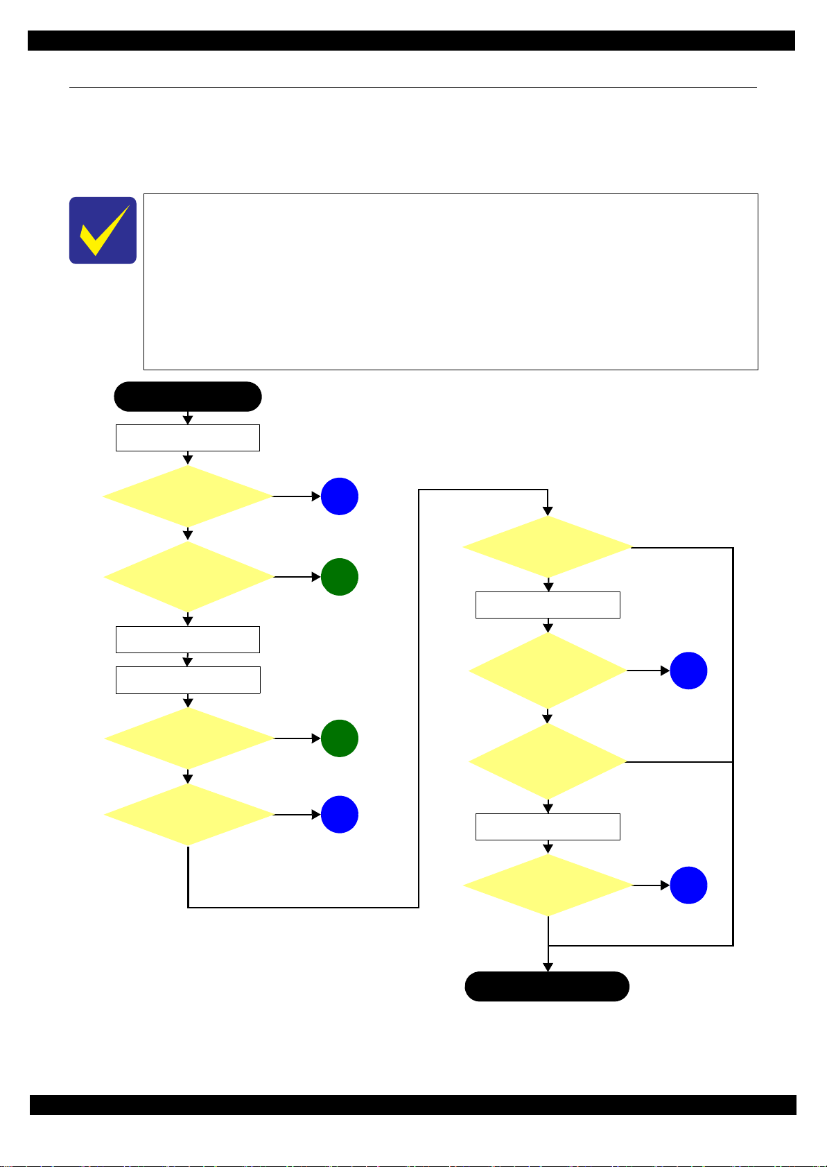
1.1 Troubleshooting
This section describes the troubleshooting workflow.
1.1.1 Troubleshooting Workflow
The following page describes the troubleshooting workflow. Follow the flow when troubleshooting problems.
This flowchart is compiled based on the following contents.
• Our experience regarding the quality problem.
• ESK’s repair data
• Printer Mechanism specification for WF-M5690/M5190 series
WF-M5190 series are not equipped with the Scanner / ADF unit, therefore, the
troubleshooting related to the Scanner / ADF unit is not applied.
If the reason for the return is evident, first check the phenomenon user claims recurs,
then proceed to the troubleshooting.
Figure 1-1. Troubleshooting Workflow (1)
Troubleshooting Troubleshooting 10
Confidential
Page 11
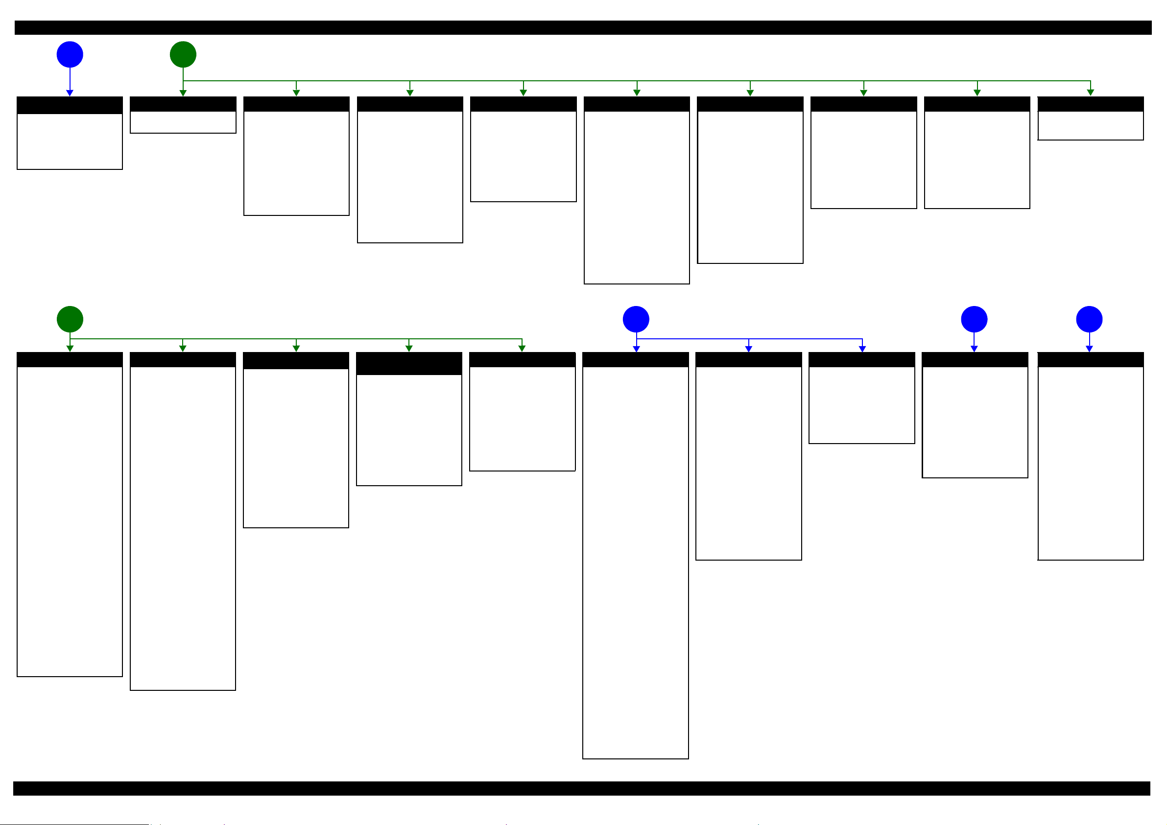
Epson WF-M5690/M5190 series Revision B
The power-on sequence
does not start (p10)
No power
[Presumable Cause]
• Damage to Power Supply Unit
• Damage to Main Board
[Remedy]
• Replace Power Supply Unit
• Replace Main Board
*1
Error is indicated during printing nozzle check pattern. (p10)
Error is indicated during power-on
21
sequence (p10)
Fatal error
See "1.1.2Power-On Sequence
(p12)".
Maintenance box full
[Occurrence Condition]
This error occurs when
maintenance counter in
Maintenance Box exceeds the
specified value.
[Occurrence Timing]
• At power-on
• When printing starts
• Cleaning
• When closing the Front Cover
[Remedy]
• Replace Maintenance Box
Maintenance box CSIC error
[Occurrence Condition]
This error occurs when
Maintenance Box data is incorrect
or cannot be recognized correctly.
[Occurrence Timing]
•At power-on
• When printing starts
•Cleaning
• When closing the Front Cover
[Remedy]
• Remove and reinstall
Maintenance Box
• Replace Maintenance Box
• Replace CSIC terminal
• Replace Maintenance Box FFC
• Replace Main Board
No maintenance box error
[Occurrence Condition]
This error occurs when
Maintenance Box is not installed.
[Occurrence Timing]
• At power-on
• When printing starts
• Cleaning
• When closing the Front Cover
[Remedy]
• Install Maintenance Box
Ink end error
[Occurrence Condition]
This error occurs when ink in Ink
Cartridge is empty.
[Occurrence Timing]
• At power-on
• When printing starts
• Cleaning
• When closing the Front Cover
• During printing
[Remedy]
• Replace Ink Cartridge
[Note]
If this error occurs during
printing, the paper will be ejected
automatically after the current
page is printed. If the error occurs
during face printing in the
automatic duplex printing, the
current page will be printed but
printing stops before reversing the
paper.
Problems related to print result or during printing (p10)
Ink cartridge detection error
[Occurrence Condition]
This error occurs when ink
cartridge data is incorrect or Ink
Cartridge is not recognized
correctly.
[Occurrence Timing]
• At power-on
• When printing starts
• Cleaning
• When closing the Front Cover
• During printing
[Remedy]
• Remove and reinstall Ink
Cartridges
• Replace Ink Cartridge
• Replace CSIC terminal
• Replace CSIC Board
• Replace CSIC FFC
• Replace Main Board
No ink cartridge error
[Occurrence Condition]
This error occurs when Ink
Cartridge is not installed.
[Occurrence Timing]
• At power-on
• When printing starts
• Cleaning
• When closing the Front Cover
• During printing
[Remedy]
• Install Ink Cartridge
Front cover open error
[Occurrence Condition]
This error occurs when Front
Cover is open.
[Occurrence Timing]
• At power-on
• During printing
[Remedy]
• Close Front Cover
• Replace Front Housing Assy
• Replace Cover Open Sensor
• Replace Main Board
Scanning cannot be
performed
5 643
successfully (p10)
Paper jam error
See "Paper jam error" which
occurs during nozzle check
pattern printing.
ADF does not
operate
normally (p10)
Paper jam error
[Occurrence Condition]
This error occurs when the top/
bottom of paper cannot be
detected by PE Sensor or PW
Sensor within the specified steps
even if the paper has been fed
correctly.
[Occurrence Timing]
• At power-on
• During feeding paper
• During ejecting paper
• During duplex printing
• When closing the Front Cover
[Remedy]
1 Press the “Start” button to eject
jammed paper.
• If succeeded
Print starts if there is printing
data.
• If failed
The paper jam error occurs
again.
2 If failed at Step 1, open the
Front Cover and remove the
Duplex Unit, and then remove
jammed paper.
3 Press the “Start” button again.
• If succeeded
Paper is fed if there is
printing data.
• If failed
The paper jam error occurs
again.
4 Check the following if failed in
Step 3.
• Foreign object
• Detached parts
• PE Sensor Lever
•PE Sensor
•PW Sensor
• Main Board
• Paper Stopper Assy
Paper out error
[Occurrence Condition]
This error occurs when the top of
paper cannot be detected by PE
Sensor within the specified steps
even if the paper has been fed
correctly. (No paper / paper
loading failed / paper is fed at
slant)
[Occurrence Timing]
• During feeding paper
[Remedy]
1 Set paper to 1st cassette or
Rear MP Tray, and press the
“Start” button.
2 If a paper stops before reaching
PE Sensor, remove it and
check the paper condition.
3 A)If paper has no damage, set
edge guide correctly after
setting paper in 1st cassette
or Rear MP Tray, and
perform Step 2 again.
B) If paper is damaged, check
for foreign materials /
detached parts / deformed
parts in the paper path.
4 If the problem is not solved by
3-A) & 3-B), check the
following.
• Foreign object
• Detached parts
• Movement of Trigger Lever
of Rear ASF
• Tension of ASF Timing Belt
• Surface condition of LD
Roller of Rear ASF, Pickup
Roller and paper feed rollers
in Duplex Unit
• PE Sensor Lever
•PE Sensor
• Main Board
•PF Motor
• Cassette Assy
• Paper Stopper Assy
Multi-feed error
[Occurrence Condition]
This error occurs on the following
case.
• A paper is ejected without
printing during paper loading
operation.
• Actual paper length is longer
than theoretical one.
[Occurrence Timing]
• During feeding paper
• During loading paper
• During ejecting paper
[Remedy]
• Replace PE Sensor Lever
• Replace PE Sensor
• Replace PW Sensor
• Replace Main Board
• Perform the operation check
and replace Paper Stopper
Assy if necessary
*2
Paper length mismatch error
for duplex printing
[Occurrence Condition]
This error occurs when actual
paper size is not matched to
theoretical one (both shorter and
longer).
[Occurrence Timing]
• During auto duplex printing
• During receiving FAX data
[Remedy]
• Replace PE Sensor Lever
• Replace PE Sensor
• Replace PW Sensor
• Replace Main Board
No paper cassette error
[Occurrence Condition]
This error occurs when Cassette
Assy 1st cannot be detected. (The
error occurs to the Cassette Assy
*3
2nd
in the same way.)
[Occurrence Timing]
• During feeding paper
*3
[Remedy]
• Check connection for Paper
Stopper Lever Sensor cable
• Replace Paper Stopper Lever
Sensor
Printing failure
[Symptoms]
• Printing failure
• Contamination on paper
• Dot missing
• Paper is ejected without printing
[Presumable Cause]
• Incorrect setting for driver/
panel
• Contamination on CR Scale
• Contamination on Printhead
Cover
• Printhead failure
• Dot missing of Printhead
• Contamination on Cap or
Wiper of Ink System Unit
• Ink System Unit failure
• PG is narrow
• Damage on PE Sensor Lever
• Damage on PE Sensor
• Damage on APG related parts
of Carriage Assy
• APG Lever operation failure
• Connection failure between
Decompress Pump Tube and
Ink Supply Unit
• Twist or blockade of
Decompress Pump Tube
• Decompress Pump Unit
operation failure
• Ink Supply Unit operation failure
• Connection failure between
Ink Supply Tube and Printhead
[Remedy]
• Check driver or panel setting
• Replace CR Scale
• Clean Printhead Cover
• Perform cleaning
• Replace Ink Cartridge
• Replace Printhead
• Clean rubber part of Cap
• Replace Ink System Unit
• Adjust PG again
• Replace Printer Mechanism
• Replace PE Sensor Lever
• Replace PE Sensor
• Replace Carriage Assy
• Check the attachment
condition of APG Lever
• Check the condition of
Decompress Pump Tube
• Replace Decompress Pump Unit
• Replace Ink Supply Unit
• Check the condition of the joint
section of Ink Supply Tube
Paper feeding failure
[Presumable Cause]
• Use of 3rd party media
• Inappropriate position of edge
guide
• Foreign object
• Detached parts
• Contamination on LD Roller of
Rear ASF / Retard Roller
• Contamination on Pickup
Roller
• Contamination on paper feed
rollers in Duplex Unit
• Damage to Cassette Assy
• Rear ASF Timing Belt tension
failure
• Damage to Rear ASF Assy
[Remedy]
• Use EPSON-recommended
paper
• Set edge guide correctly
• Remove foreign material
• Re-install parts
• Replace Pickup Assy
• Replace Cassette Assy
• Replace Printer Mechanism
• Replace Rear ASF Assy
Note *1: If the printer can turn on but turns off right away, the protection circuit may cut off the power due
Abnormal noise
[Presumable Cause]
• Foreign object
• Insufficient grease
• Damage to gears
[Remedy]
• Remove foreign material
• Apply an appropriate amount
of grease
• Replace gears
to an error such as a circuit failure.
*2: Only for manual duplex printing
*3: WF-M5690 series only
Scanner failure
[Presumable Cause]
• Contamination on document
glass
• Contamination on Document
Pad
• CIS bonding failure
• CIS failure
• Damage to Scanner Motor
[Remedy]
• Clean document glass
• Clean Document Pad
• Replace Document Pad
• Replace CIS Unit
• Replace Scanner Motor
ADF failure
[Symptoms]
• Paper is not fed
• Multi-feed
• Paper jam
• Skewed document
[Presumable Cause]
• Deterioration of Pickup Roller
• Deterioration of ADF Pad
Assy
• Damage to gears
•Damage to ADF Motor
• Contamination on document
glass
• Foreign object
• Damage to ADF Cover Assy
• Deterioration of Paper Eject
Roller
• Damage to ADF Document
Sensor / ADF PE Sensor
[Remedy]
• Replace ADF Cover Assy
• Replace ADF Pad Assy
• Clean document glass
• Remove foreign material
• Replace ADF Unit
Troubleshooting Troubleshooting Workflow 11
Confidential
Page 12
Epson WF-M5690/M5190 series Revision B
0
0
0
0
0
0
80 0
HP
0
0
0
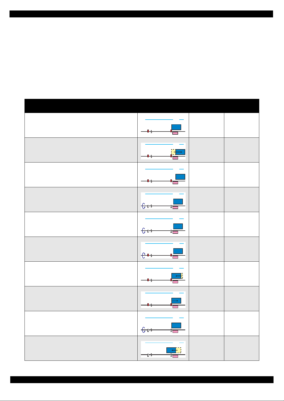
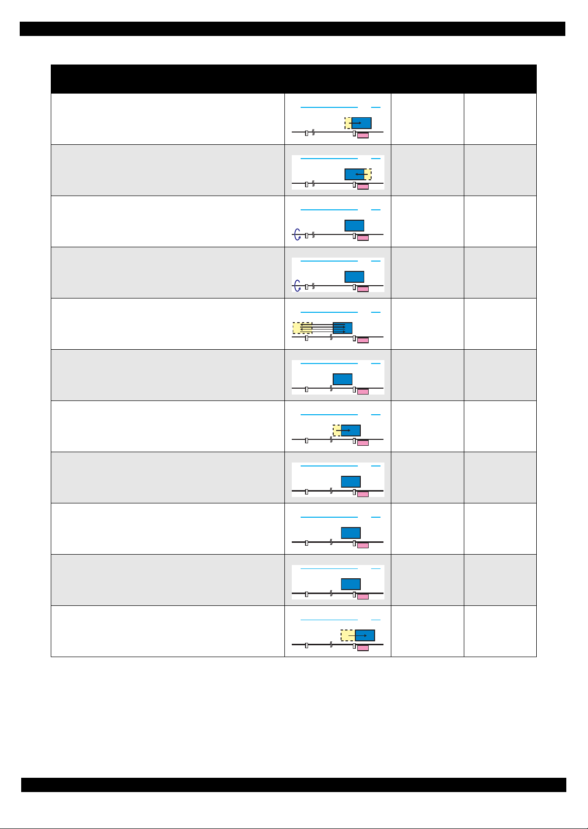
1.1.2 Power-On Sequence
This section describes the power-on sequences for this product. The preconditions are as follows.
Normal power-on sequence
Turning on the printer after turning it off without an error.
Initial ink charge has finished and every cartridge has sufficient ink.
No paper on the paper path.
The Printhead is capped by the cap of Ink System and the CR Lock is engaged normally.
The carriage is locked by the CR lock.
PG position is set to PG1.
Table 1-1. Power-On Sequence
Operation
1. Printhead initialization and fuse inspection
1-1.Initializes the Printhead, and checks the fuse on the printer
control circuit board.
2. Seeking the home position
2-1.The carriage moves to the 0-digit side slowly and confirms it
touches the Right Frame.
2-2.Regards the position where the carriage touches the Right Frame
as the position of the specified steps from the home position, and
set it as the origin position.
2-3.The carriage slowly moves the CR lock set position.
2-4.The PF Motor rotates clockwise and releases the CR lock.
2-5.The PF Motor rotates counterclockwise and sets the CR lock.
Movement of
Components
80
80
80
80
80
80
HP
HP
HP
HP
HP
HP
Front ASF drive
condition
OFF ---
↓
↓
↓
↓
↓
Decompress
motor
---
---
---
---
---
2-6.The carriage moves to the 80-digit side slowly and confirms it
touches the CR lock.
---
---
---
2-7.The carriage returns to its home position.
2-8.The PF Motor rotates clockwise and releases the CR lock.
3. Switching front ASF drive
3-1.The carriage moves to the 80-digit side slowly up to position
where the Front ASF turn on.
↓
80
HP
↓
80
HP
↓
80
HP
ON ---
Troubleshooting 12
Confidential
Page 13
Epson WF-M5690/M5190 series Revision B
0
0
0
0
0
0
0
0
0
0
0
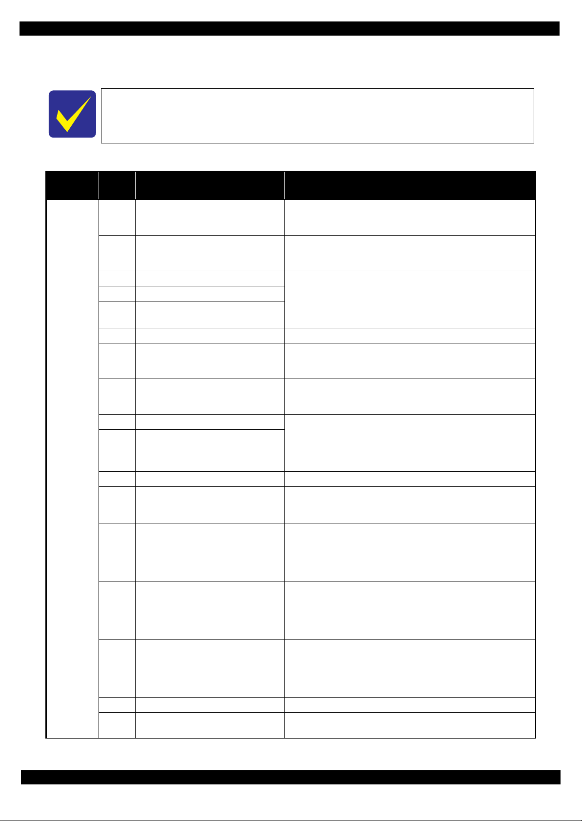
Table 1-1. Power-On Sequence
Operation
3-2.The carriage moves to the 0-digit side slowly up to the position
where the Front ASF turn off.
3-3.The carriage moves to the 80-digit side slowly and passes by the
CR lock.
4. PF initialization
4-1.The PF Motor rotates clockwise for approximately one second.
4-2.The PE sensor checks if paper exists, and the PF Motor rotates
clockwise for approximately 0.5 seconds.
5. Low temperature operation sequence
5-1.The carriage moves back and forth between CR lock and the left
Frame two times.
6. Checking waste ink overflow
6-1.Reads out the waste ink counter value of the Maintenance Box
to check waste ink overflow.
Movement of
Components
80
80
80
80
80
80
HP
HP
HP
HP
HP
HP
Front ASF drive
condition
OFF ---
↓
↓
↓
↓
↓
Decompress
motor
---
---
---
---
---
7. Detecting ink cartridge and initializing ink system
7-1.The carriage moves slowly to the ink detection position.
80
HP
↓
7-2.The Decompress Motor is driven and Diaphragm Pump sucks
the ink in the ink cartridges.
80
HP
↓
Decompress
and vent to
atmosphere
7-3.While monitoring the ink end sensor, the Decompress Motor is
driven again and the Diaphragm Pump sucks the ink.
80
HP
↓
Decompress
and vent to
atmosphere
7-4.Detects the ink remaining.
80
HP
↓
7-5.The carriage returns to its home position.
80
HP
↓
Note *1: On the premise on this table, PG does not change and the Rear ASF does not operate during the sequence.
*2: Executes when the detected temperature is under 5 ℃ (41)by the thermistor on the Printhead.
*3: The Printhead is capped with the Cap of the Ink System but the Carriage is not locked by the CR lock in order to shorten the
time before printing starts. The Carriage is locked when the printer enters the power saving mode without any operation after it
is turned on.
---
---
---
Troubleshooting 13
Confidential
Page 14
Epson WF-M5690/M5190 series Revision B
1.1.3 Fatal Error
This section describes the fatal error code and the possible cause for this product.
Fatal errors related to the ADF/Scanner unit do not occur for WF-M5190 series because this
model does not have ADF/Scanner unit.
Table 1-2. Fatal Error List
Error type
ADF/
Scanner
Error
code
0x01 ADF PID excess speed error
0x02 ADF PID reverse error
0x03 ADF PID lock error • ADF Encoder failure (contaminated/detached scale, Encoder Board
0x04 ADF PID acceleration lock detection error
0x05 ADF PID excess load error
0x06 ADF PID driving time error • Main Board failure
0x09 ADF BS+ excess speed error
0x0A ADF BS+ reverse error
0x0B ADF BS+ lock error • ADF Encoder failure (contaminated/detached scale, Encoder Board
0x0D ADF BS+ excess load error
0x0E ADF BS+ driving time error • Main Board failure
0x10 HP detection error
0x11 Contact detection distance exceeded error
0x12
0x13
0x14 Measurement failure error • Scanner drive mechanism was overloaded.
0x20 LED light error
Opposite side contact detection distance
exceeded error
Opposite side wrong contact detection
distance error
Error name Possible cause
• ADF Encoder failure (contaminated/detached scale, Encoder Board
failure)
• Motor driver failure (Main Board f ailu re)
• ADF Encoder failure (contaminated/detached scale, Encoder Board
failure)
• Paper jam
failure)
• ADF Motor failure
• Paper jam
• Cable disconnection
• ADF Encoder failure (contaminated/detached scale, Encoder Board
failure)
• Motor driver failure (Main Board f ailu re)
• ADF Encoder failure (contaminated/detached scale, Encoder Board
failure)
• Paper jam
failure)
• ADF Motor failure
• ADF drive overload (paper jam/foreign object)
• Cable disconnection
• CIS Unit failure
• Scanner Housing failure
• Main Board failure
• CIS Unit failure
• Scanner Housing failure (Including wrong attachment of the origin mark)
• Main Board failure
• Scanner FFC failure / Scanner FFC connection failure
• Scanner Motor failure / Scanner Motor connection failure
• CIS Unit failure
• Scanner Housing failure (Including wrong attachment of the origin mark)
• Main Board failure
• Scanner FFC failure / Scanner FFC connection failure
• Scanner Motor failure / Scanner Motor connection failure
• CIS Unit failure
• Scanner housing failure (Includin g wrong attachment of the origin mark)
• Main Board failure
• Scanner FFC failure / Scanner FFC connection failure
• Scanner Motor failure / Scanner Motor connection failure
• CIS Unit failure
• Main Board failure
Troubleshooting 14
Confidential
Page 15
Epson WF-M5690/M5190 series Revision B
Table 1-2. Fatal Error List
Error type
ADF/
Scanner
PDL 0x5F Main ROM and μSD ROM matching error • Mismatch the Main ROM FW version and μSD ROM FW version.
Error
code
0x30 Option error • Main Board failure
0x36 Paper jam error
0x41 FB PID excess speed error
0x42 FB PID reverse error
0x43 FB PID lock error • ADF Encoder failure (contaminated/detached scale, Encoder Board
0x44 FB PID acceleration lock
0x45 FB PID excess load error
0x46 FB PID driving time error • Main Board failure
0x49 FB BS+ excess sped error
0x4A FB BS+ reverse error
0x4B FB BS+ lock error • ADF Encoder failure (contaminated/detached scale, Encoder Board
0x4D FB BS+ excess load error
0x4E FB BS+ driving time error • Main Board failure
0x51 Automatic judgement fatal error 1
0x52 Automatic judgement fatal error 2
0x53 Automatic judgement fatal error 3
0x54 Automatic judgement fatal error 4
0x55 Automatic judgement fatal error 5
Error name Possible cause
• Paper jam
• Foreign object
• ADF Encoder failure (contaminated/detached scale, Encoder Board
failure)
• Motor driver failure (Main Board f ailu re)
• ADF Encoder failure (contaminated/detached scale, Encoder Board
failure)
• Paper jam
failure)
• ADF Motor failure
• ADF drive mechanism overload (assembling failure, lubrication failure)
• Cable disconnection
• ADF Encoder failure (contaminated/detached scale, Encoder Board
failure)
• Motor driver failure (Main Board f ailu re)
• ADF Encoder failure (contaminated/detached scale, Encoder Board
failure)
failure)
• ADF Motor failure
• ADF drive mechanism overload (assembling failure, lubrication failure)
• Cable disconnection
---*
Troubleshooting 15
Confidential
Page 16

Epson WF-M5690/M5190 series Revision B
Table 1-2. Fatal Error List
Error type
Printer
Error
code
0x60 HP error
0x61 Deadlock avoidance error
0x62 Impossible contact detection error
0x6B PF runaway error
0x7F Inspection mode error ---*
0x8A Ink Leak detect error
0x8D Factor error other than printer device
0x8E Driver mismatch error An unsupported driver was used.
0x8F EEPROM verify error (by command) ---*
0x90 PW Sensor failure error • PW sensor failure
0x91 PW Sensor detected foreign object error
0x92 Hot plug disconnection paper jam error
0x93 PE Sensor error
Error name Possible cause
• Paper jam
• Foreign object
• Deformation of the Main Frame
• PF Encoder failure (contaminated/detached scale, Encoder Board failure)
• Motor drive error
• Occur th e Ink Leak at ink supply route .
• Printhead failure
• Ink Supply Unit failure
This error occurs if the printer becomes a fatal error status due to a failure of
parts other than the printer such as the scanner or ADF
• Main Board failure
• Foreign object
• 2nd Cassette Unit has been removed during feeding (when the ASF
Motor is operating).
• Contact failure of the connector which contacts 2nd Cassette Unit and the
printer.
• PE Sensor failure
• Main Board failure
Troubleshooting 16
Confidential
Page 17
Epson WF-M5690/M5190 series Revision B
Table 1-2. Fatal Error List
Error type
Printer
Error
code
0x94 PW Sensor light value adjust error
0x96 Decompress pump motor driving time error
0x97 Head drive circuit VBS over-voltage error
0x98 HCS error
0x99 IES process check error ---*
0x9A Circuit error (include blowout of a fuse)
0x9B Transistor temperature error
0x9C X-Hot detect error (pre printing)
0x9D X-Hot detect error (after flushing)
0x9E Head temperature error
0x9F No print inspection mode error ---*
0xB8 CRCM access error
0xB9 -
0xBA
0xBD -
0xC2
0xC3 Ink device error
0xC4 -
0xCF
0xD1 ASF PID excess load error
0xD2 ASF PID excess speed error
0xD3 ASF PID reverse error
0xD4 ASF PID lock error
Ink device error
CRCM access error
CRCM access error
Error name Possible cause
• PW Sensor failure
• Main Board failure
• Decompress pump motor failure
• Main Board failure
• Head FFC failure
• Main Board failure
• Printhead failure
• Head FFC failure
• Main Board failure
• Main Board failure
• Printhead failure
• Main Board failure
• CR Contact Module failure
• CRCM FFC disconnection
• Main Board failure
• Ink cartridge failure
• CSIC Terminal failure
• CR Contact Module failure
• Main Board failure
• CR Contact Module failure
• CRCM FFC disconnection
• Main Board failure
• Ink cartridge failure
• CSIC Terminal failure
• CR Contact Module failure
• Main Board failure
• CR Contact Module failure
• CRCM FFC disconnection
• Main Board failure
• ASF Encoder failure (contaminated/detached scale, Encoder Board
failure)
• ASF Motor failure
• Pickup Roller (2nd cassette) drive mechanism overload (paper jam /
foreign object)
• Cable disconnection
• ASF Encoder failure (contaminated/detached scale, Encoder Board
failure)
• Motor driver failure (Main Board f ailu re)
• ASF Encoder failure (contaminated/detached scale, Encoder Board
failure)
• Paper jam
• ASF Encoder failure (contaminated/detached scale, Encoder Board
failure)
• ASF Motor failure
• Pickup Roller (2nd cassette) drive mechanism overload (paper jam /
foreign object)
• Cable disconnection
Troubleshooting 17
Confidential
Page 18

Epson WF-M5690/M5190 series Revision B
Table 1-2. Fatal Error List
Error type
Printer
Error
code
0xD8 ASF load position reverse error
0xD9 ASF load position excess speed error
0xDA ASF load position excess load error
0xDE ASF PID driving time error
0xDF ASF load position driving time error
0xE1 CR PID excess load error
0xE2 CR PID excess speed error
0xE3 CR PID reverse error
0xE4 CR PID lock error
0xE5 CR PID speed fall error
0xE8 CR load position reverse error
0xE9 CR load position excess speed error
0xEA CR load position excess load error
0xEE CR PID driving time error
0xEF CR load position driving time error
0xF1 PF PID excess load error
Error name Possible cause
• ASF Encoder failure (contaminated/detached scale, Encoder Board
failure)
• Paper jam
• ASF Encoder failure (contaminated/detached scale, Encoder Board
failure)
• Motor driver failure (Main Board f ailu re)
• ASF Encoder failure (contaminated/detached scale, Encoder Board
failure)
• ASF Motor failure
• Pickup Roller (2nd cassette) driven mechanism overload (paper jam/
foreign object)
• Cable disconnection
• Main Board failure
• CR Encoder failure (contaminated/detached scale, Encoder board failure)
• CR Motor failure
• Carriage overload error (paper jam/foreign object)
• Cable disconnection
• CR Encoder failure (contaminated/detached scale, Encoder board failure)
• Motor driver failure (Main Board f ailu re)
• Tooth skip of the CR Timing Belt
• Improper tension of the CR Timing Belt
• CR Encoder failure (contaminated/detached scale, Encoder board failure)
• Tooth skip of the CR Timing Belt
• Improper tension of the CR Timing Belt
• Paper jam
• CR Encoder failure (contaminated/detached scale, Encoder Board failure)
• CR Motor failure
• Carriage overload error (paper jam/foreign object)
• Cable disconnection
• CR Encoder failure (contaminated/detached scale, Encoder Board failure)
• Motor driver failure (Main Board f ailu re)
• Tooth skip of the CR Timing Belt
• Improper tension of the CR Timing Belt
• Paper jam
• CR Encoder failure (contaminated/detached scale, Encoder Board failure)
• Tooth skip of the CR Timing Belt
• Improper tension of the CR Timing Belt
• Paper jam
• CR Encoder failure (contaminated/detached scale, Encoder Board failure)
• Motor driver failure (Main Board f ailu re)
• Tooth skip of the CR Timing Belt
• Improper tension of the CR Timing Belt
• CR Encoder failure (contaminated/detached scale, Encoder Board failure)
• CR Motor failure
• Carriage overload error (paper jam/foreign object)
• Cable disconnection
• Main Board failure
• PF Encoder failure (contaminated/detached scale, Encoder Board failure)
• PF Motor failure
• PF drive mechanism overload (paper jam/foreign object)
• Cable disconnection
Troubleshooting 18
Confidential
Page 19

Epson WF-M5690/M5190 series Revision B
Table 1-2. Fatal Error List
Error type
Printer
Error
code
0xF2 PF PID excess speed error
0xF3 PF PID reverse error
0xF4 PF PID lock error
0xF6 PF PID Torque limit error
0xF8 PF load position reverse error
0xF9 PF load position excess speed error
0xFA PF load position excess load error
0xFE PF PID driving time error
0xFF PF load position driving time error
Error name Possible cause
• PF Encoder failure (contaminated/detached scale, Encoder Board failure)
• Motor driver failure (Main Board f ailu re)
• Tooth skip of the PF Timing Belt
• Improper tension of the PF Timing Belt
• PF Encoder failure (contaminated/detached scale, Encoder Board failure)
• Tooth skip of the PF Timing Belt
• Improper tension of the PF Timing Belt
• Paper jam
• PF Encoder failure (contaminated/detached scale, Encoder Board failure)
• PF Motor failure
• PF driver mechanism overload (paper jam/foreign object)
• Cable disconnection
• PF Encoder failure (contaminated/detached scale, Encoder Board failure)
• PF Motor failure
• PF driver mechanism overload (paper jam/foreign object)
• Improper tension of the PF Timing Belt
• Tooth skip of the PF Timing Belt
• PF Encoder failure (contaminated/detached scale, Encoder Board failure)
• Tooth skip of the PF Timing Belt
• Improper tension of the PF Timing Belt
• PF Encoder failure (contaminated/detached scale, Encoder Board failure)
• Motor driver failure (Main Board f ailu re)
• Tooth skip of the PF Timing Belt
• Improper tension of the PF Timing belt
• PF Encoder failure (contaminated/detached scale, Encoder Board failure)
• PF Motor failure
• PF driver mechanism overload (paper jam/foreign object)
• Cable disconnection
• Main Board failure
.
Troubleshooting 19
Confidential
Page 20
Epson WF-M5690/M5190 series Revision B
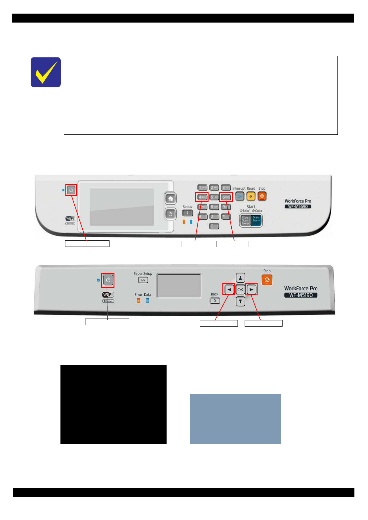
Power on button
No.4 button No.6 button
Power on button
Left button Right button
Maintenance SP Mode
1. Status Sheet Print mode
Inspection Mode
1. STSheet Mode
[WF-M5690 series]
[WF-M5190 series]
Run : Color / Select : [3][6]
1.1.4 Status sheet
This section describes the Status sheet for this product.
This product can print the three kind of status sheet, and you can confirm the following
information.
• C o nfiguration Status Sheet
• Supply Status Sheet
• Usage History Sheet
This product has Non-disclosed information to user.
This information can be displayed on the Status sheet by starting the product with the
Maintenance SP Mode.
1.1.4.1 Start method of Maintenance SP Mode
1. From a power off status, push the following buttons until the message is displayed on LCD.
WF-M5690 series
WF-M5190 series
2. Select the following items from the Inspection menu.
WF-M5690 series : “1. Status Sheet Print Mode”
WF-M5190 series : “1. STSheet Mode”
3. The product starts as usual.
Troubleshooting 20
Confidential
Page 21
Epson WF-M5690/M5190 series Revision B
4. Print the status sheets.
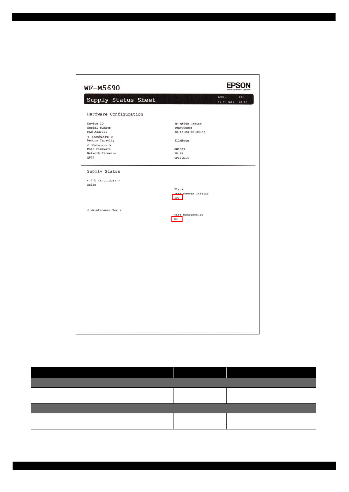
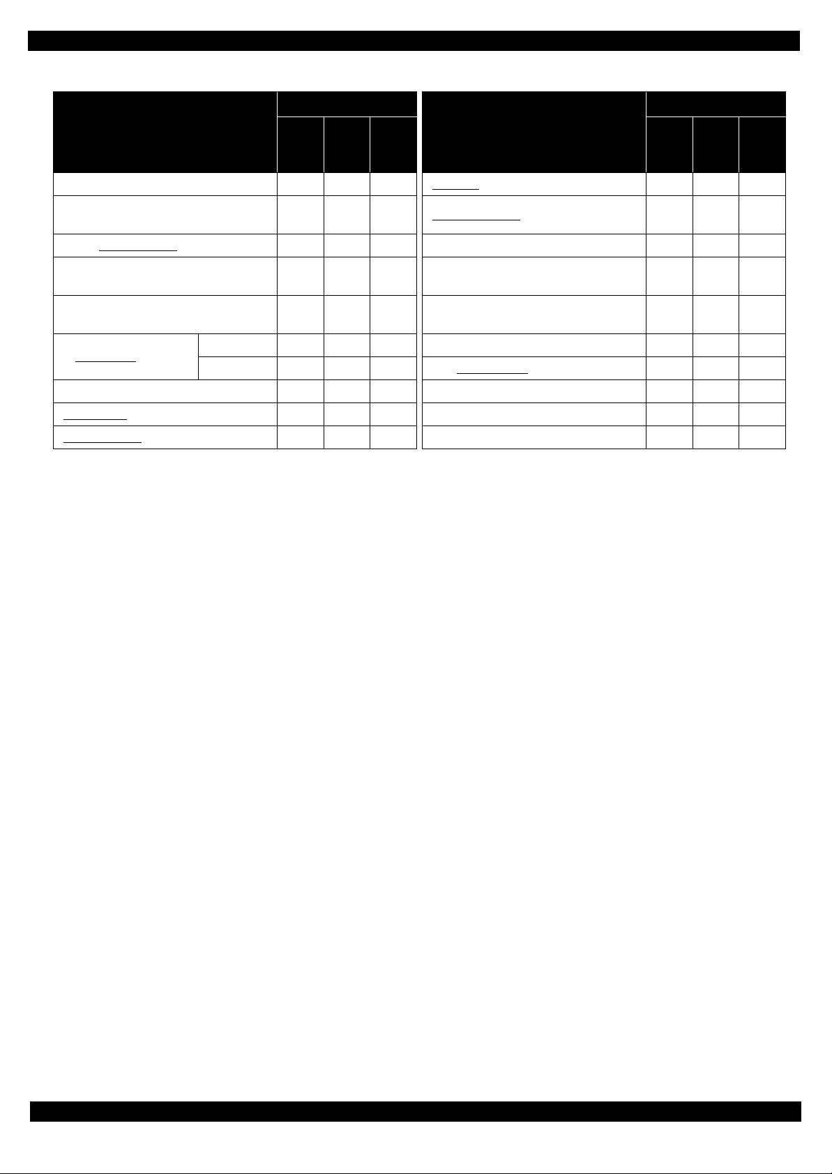
1.1.4.2 Description of Status sheet (Non-disclosed information to user)
Supply Status sheet
Figure 1-1. Supply Status Sheet (Non-disclosed information to user)
Item Content Item Content
Consumable information <Ink Cartridge>
Ink residual quantity Residual quantity information of the
Ink Cartridge.
Consumable information <Maintenance Box>
Maintenance Box
residual quantity
Residual quantity information of the
Maintenance Box.
Troubleshooting 21
Confidential
Page 22
Epson WF-M5690/M5190 series Revision B
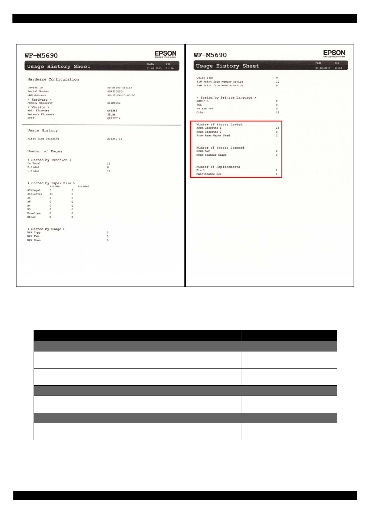
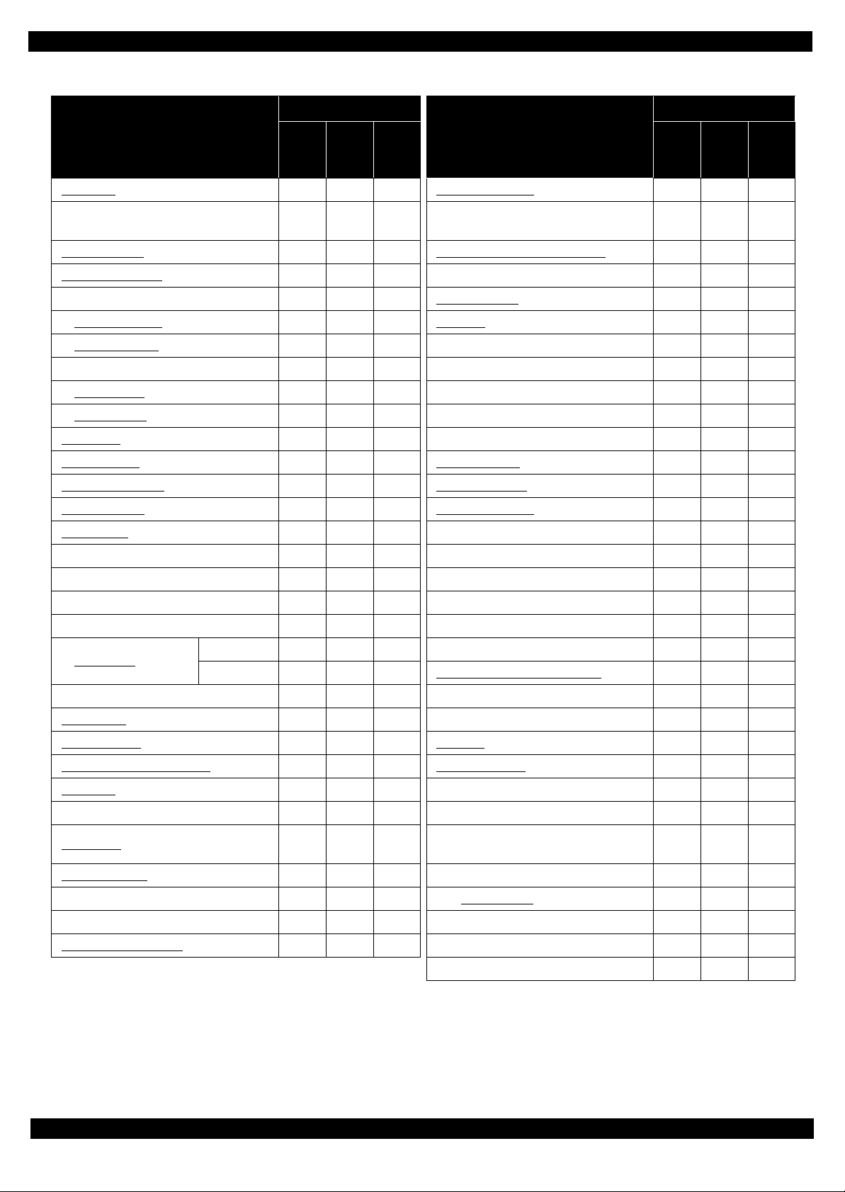
Usage History Sheet
Figure 1-2. Usage History Sheet (Non-disclosed information to user)
Item Content Item Content
Number of Sheets Loaded
Casette 1 Number of sheets loaded from 1st
cassette.
Rear Paper Feed Number of sheets loaded from rear
paper feed tray.
Number of Sheets Scanned
ADF Number of sheets scanned from ADF
Unit.
Number of Replacement
Ink Cartridge Number of replacement of Ink
cartridge
Cassette 2 Number of sheets loaded from 2nd
cassette.
Scanner Glass Number of sheets scanned from
Scanner Glass.
Maintenance Box Number of replacement of
Maintenance Box.
Troubleshooting 22
Confidential
Page 23

CHAPTER 2
DISASSEMBLY/REASSEMBLY
Confidential
Page 24

Epson WF-M5690/M5190 series Revision B
2.1 Overview
In this manual, the product name is abbreviated to such as “WP-4510 series”, however, the
last digit of the actual name may differ. Identify your product with the first three digits and
refer to the appropriate sections in this manual.
This chapter describes procedures for disassembling the main parts/units of WP-M5690/M5190 series. Unless
otherwise specified, disassembled parts/units can be reassembled by reversing the disassembly procedure. See
the cautions or tips for disassembly/reassembly described in "2.3 Detailed Disassembly/Reassembly Procedure
for each Part/Unit (p41)".
Read the "Safety Precautions (p3)" before disassembling and reassembling.
When you have to remove units or parts that are not described in this chapter, see the exploded diagrams of SPI
(Service Parts Information).
2.1.1 Tools
Use only specified tools to avoid damaging the printer.
Name Availability EPSON Part Code
(+) Phillips screwdriver #1 O 1080530
(+) Phillips screwdriver #2 O --Flathead screwdriver O --Flathead Precision screwdriver #1 O --Tweezers O --Longnose pliers O --Acetate tape --- 1003963
Tube Clip O
Note 1: Some of the tools listed above are commercially available.
2: EPSON provides the tools listed with EPSON part code.
2.1.2 Jigs
Name Quantity EPSON Part Code
Spacer (5 mm) 1 --Ink Leak Measurement Jig 1 1650703
Ink Leak Check Cartridge 1 1565785
Disassembly/Reassembly Overview 24
Confidential
Page 25
Epson WF-M5690/M5190 series Revision B
2.1.3 Standard Operation Time for servicing the product
The following are the standard operation time for servicing the product. Those are base on the MTTR result measured
using a prototype.
The underlined parts/units are supplied as After Service parts.
Standard Operation Time for servicing WF-M5690 series : See Table 2-1
Standard Operation Time for servicing WF-M5190 series : See Table 2-2
Table 2-1. Standard Operation Time (WF-M5690 series)
Time (second)
Parts/Unit
Panel Unit
Metal Plate
(Including Paper Stopper Assy)
Pickup Assy 1st
Paper Stopper Assy
Cover ASF Assy 10 0 10 PF Encoder FFC
Cover ASF Front
Cover ASF Rear
ADF Pad Assy
Housing Rear Assy 49 0 49 Power Supply Unit
Housing Rear
Paper Support
FAX Cover
Speaker/Speaker Holder
ADF/Scanner Unit 314 135 449 Printhead
ADF Unit
ADF Rear Cover
ADF Cover Assy
ADF Cover Housing Upper 710 0 710 CR Motor 1164 30 1194
LD Cover 726 0 726 Maintenance Box Ink Eject Joint 775 0 775
LD Shaft 730 0 730 Ink System Unit
Extension Spring 758 0 758 Option Connecter
ADF LD Assy
ADF Document Support Assy
Scanner Unit
Front Housing Assy
Stacker Assy
Middle Housing
Main Board Unit 725 1108 1833 Compound Gear 16,10.6 839 0 839
Main Board Cable Holder 737 0 737 CR Scale/Extension Spring 2.03
Shield Plate Holder 772 0 772 Front Frame Assy 1476 701 2177
Main Board Shield plate Upper Assy 972 0 972 Star Wheel Assy 1398 91 1489
Repla
ceme
Adjus
tment
nt
60 25 85 Rear ASF Guide Upper Assy 552 0 552
80 0 80 CSIC FFC 488 0 448
93 0 93 Metal Plate Left 515 0 515
31 0 31 PF Encoder 529 0 529
14 0 14 PF Tension Stopper Holder 546 15 561
14 0 14 PF Timing Belt 561 15 576
10 0 10 Decompress Pump Unit 560 0 560
64 0 64 CR Cover 455 0 455
64 0 64 Ink Supply unit Grounding Plate 481 0 481
81 0 81 Ink System Supply Assy 739 1777 2516
86 0 86 Ink Supply Unit 693 1088 1781
595 135 730 Fasten Plate Center 966 0 966
628 0 628 Fasten Plate Left 1073 0 1073
641 0 641 Driven Pulley Assy 1115 15 1130
803 0 803 Shaft Drive Pickup 947 0 947
651 0 651 ASF Drive Change lever Assy 837 0 837
595 135 730 ASF Drive Change Lever Holder 839 0 839
374 0 374 Spur Gear 11.2 839 0 839
386 0 386 Extension Spring 0.63 839 0 839
441 0 441 Spur Gear 11.2 839 0 839
Total
Parts/Unit
Time (second)
Repla
ceme
1363 0 1363
Adjus
tment
nt
552 0 552
606 187 793
648 2565 3213
799 0 799
829 0 829
Total
Disassembly/Reassembly Overview 25
Confidential
Page 26
Epson WF-M5690/M5190 series Revision B
Table 2-1. Standard Operation Time (WF-M5690 series)
Time (second)
Parts/Unit
Interface Board Assy 1029 0 1029 EJ Roller 1545 352 1997
Interface Board Shield Plate
Upper
Interface Board 1076 0 1076 Main Frame Mounting Plate 1599 0 1599
Interface Board Shield Plate
Lower
Main Board Shield Plate Upper 1029 0 1029
Read OK 1033 370 1403 CR Guide Frame 2090 1193 3283
Main Board
Read NG 1033 1108 2141 Carriage Assy
Main Board Shield Plate Lower 1033 0 1033 Main Frame Assy 2332 1485 3817
Wi-Fi Board
Rear ASF Assy
Repla
ceme
1059 0 1059 Frame Base Assy
1076 0 1076 Support Plate Right/Left 1630 250 1880
Adjus
tment
nt
463 0 463 Paper Guide Upper Assy 2440 526 2966
515 140 655 PE Lever Holder Assy 2390 0 2390
Total
CR Guide Frame
(Including Carriage Assy)
Parts/Unit
Time (second)
Repla
ceme
1574 1596 3170
2082 1193 3275
2090 1438 3528
Adjus
tment
nt
Total
Disassembly/Reassembly Overview 26
Confidential
Page 27
Epson WF-M5690/M5190 series Revision B
Table 2-2. Standard Operation Time (WF-M5190 serie s)
Time (second)
Parts/Units
Panel Unit 19 0 19 Power Supply Unit 470 187 657
Metal Plate
(Including Paper Support Assy)
Pickup Assy 1st
Paper Stopper Assy
Cover ASF Assy 10 0 10 Ink Supply Unit
Cover ASF Front
Cover ASF Rear
Housing Rear Assy 49 0 49 F asten Plate left 937 0 937
Housing Rear
Paper Support
USB Cover
Housing Upper
Front Housing Assy
Middle Housing
Stacker Assy
Main Board Unit 589 1108 1697 ASF Drive Change Lever Holder 703 0 703
Main Board Cable Holder 601 0 601 Spur Gear 11.2 703 0 703
Shield Plate Holder 636 0 636 Extension Spring 0.63 703 0 703
Main Board Shield Plate 818 0 818 Spur Gear 11.2 703 0 703
Read OK 862 370 1232 Compound Gear 16,10.4 703 0 703
Main Board
Read NG 862 1108 1970 CR Scale/Extension Spring 2.03
Main Board Shield Plate Lower 862 0 862 Front Frame Assy 1189 701 1890
Wi-Fi Board
Rear ASF Assy
Rear ASF Guide Upper Assy
CSIC FFC
Metal Plate Left 379 0 379 Support Plate Right/Left 1343 250 1593
PF Encoder 393 0 393
PF Encoder FFC 406 0 406 CR Guide Frame 1739 1193 2932
PF Tension Stopper Holder 410 15 425 Carriage Assy
PF Timing Belt 425 15 440 Main Frame Assy 1981 1485 3466
Decompress pump Unit
Repla
ceme
Adjus
tment
nt
80 0 80 CR Cover 319 0 319
93 0 93 Ink Supply Unit Grounding Plate 345 0 345
31 0 31 Ink System Supply Assy 603 1777 2380
14 0 14 Printhead 554 2565 3119
14 0 14 Fasten Plate Center 830 0 830
64 0 64 Driven Pulley Assy 979 15 979
64 0 64 CR Motor 1028 30 1058
81 0 81 Maintenance Box Ink Eject Joint 639 0 639
97 0 97 Ink System Unit 663 0 663
157 0 157 Option Connecter 693 0 693
305 0 305 Shaft Drive Pickup 811 0 811
169 0 169 ASF Drive Change Lever Assy 701 0 701
327 0 327 Star Wheel Assy 1111 91 1202
379 140 519 EJ Roller 1227 352 1579
416 0 416 Frame Base Assy 1287 1596 2883
352 0 352 Main Frame Mounting plate 1312 0 1312
424 0 424 Paper Guide Upper Assy 2089 526 2615
Total
CR Guide Frame Assy
(Including Carriage Assy)
PE Lever Holder Assy 2089 0 2089
Pats/Units
Time (second)
Repla
ceme
Adjus
tment
nt
559 1088 1647
1076 0 1076
1731 1193 2924
1739 1438 3177
Total
Disassembly/Reassembly Overview 27
Confidential
Page 28
Epson WF-M5690/M5190 series Revision B
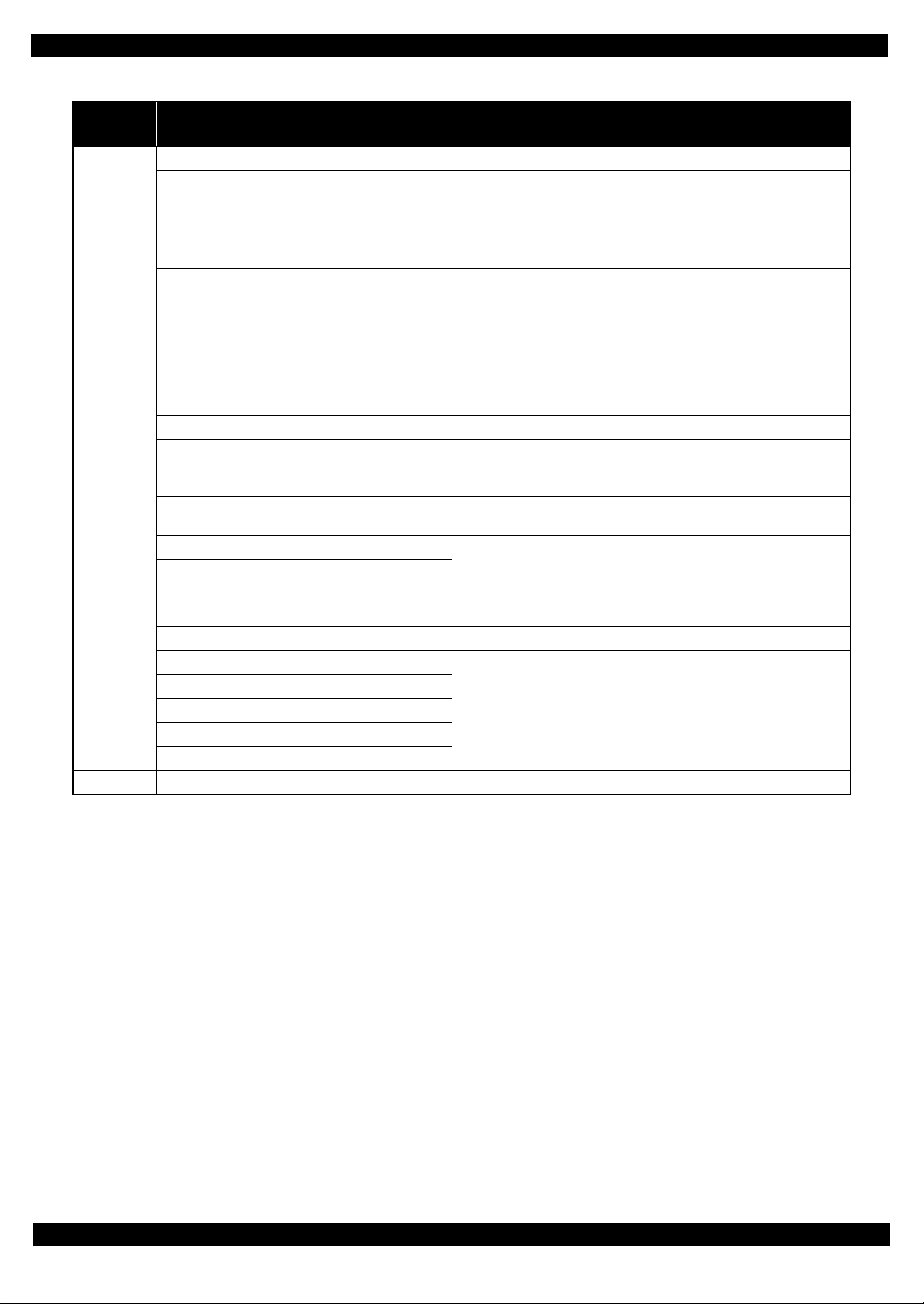
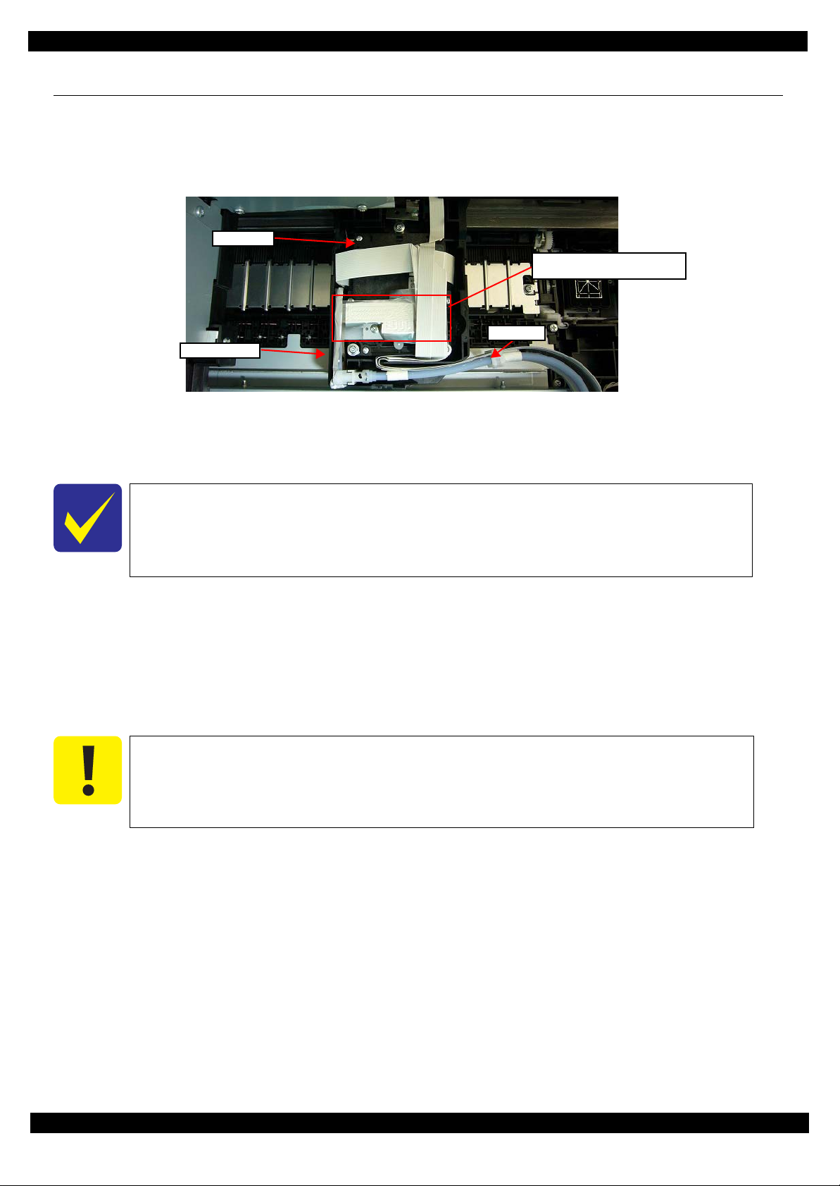
Joint section of the Printhead
and Ink Supply Unit
Printhead
Ink tubes
Carriage Assy
2.2 Disassembly/Reassembly Procedures
2.2.1 Caution when Replacing the Printhead/Ink Supply Unit
For stable ink supply, this product employs a mechanism where the ink in the ink path is pressurized even the power is
off. Therefore, if the joint section of the printhead and the Ink Supply Unit is simply disconnected, the ink in the ink
tube will spill over.
Figure 2-1. Joint Section of the Printhead and Ink Supply Unit
To prevent this from happening, before separating the Printhead and Ink Supply Unit to replace the Printhead or the
Ink Supply Unit, make sure to release the pressure inside the ink path using the Adjustment Program. The following
explains the procedure.
This is not necessary when replacing the Printhead and Ink Supply Unit together.
Approximately two minutes are required to release the applied pressure.
The ink in the ink path is pressurized in the power-off sequence again, therefore, make
sure not to turn the power off by the power button after the applied pressure is released.
Tools
Ink Cartridges Do not use user’s ink cartridges since the ink in the ink cartridges is consumed when releasing the
pressure. Prepare ink cartridges supplied as consumables for this procedure. (Hereafter, an ink cartridge for this purpose
is called as an “ink cartridge (for service use)”.
Maintenance box
Do not use user’s maintenance box since the ink the ink path flows to the maintenance box when releasing the pressure.
Prepare maintenance box supplied as a consumable for this procedure. (Hereafter, a maintenance box for this purpose is
called as a “maintenance box (for service use)”.
Make sure to use the same service Ink cartridge and Maintenance Box from “ Ink
Pressure release” to “Initial Charge”.
Before performing Ink Pressure Release, confirm the proportion of remaining capacity
of the Maintenance Box is 30% or more.
Procedure
1. Remove the ink cartridges and maintenance box in the returned unit, and install the ink cartridges
and maintenance box
(for service use).
(for service use)
2. Connect the printer and the PC installed the Adjustment Program with the USB cable, and turn the power on.
3. Start the Adjustment Program, and select the “Ink Pressure Release” from the menu.
4. Click “Execute” in the displayed screen to release the applied pressure.
5. When the completion message appears, unplug the computer power cable.
Afterward, remove the parts referring to "2.2.2 Parts/Units Need to be Removed in Advance (p32)" and replace them
referring to "2.2.3 Disassembly Flowchart (p33)".
Disassembly/Reassembly Disassembly/Reassembly Procedures 28
Confidential
Page 29
Epson WF-M5690/M5190 series Revision B
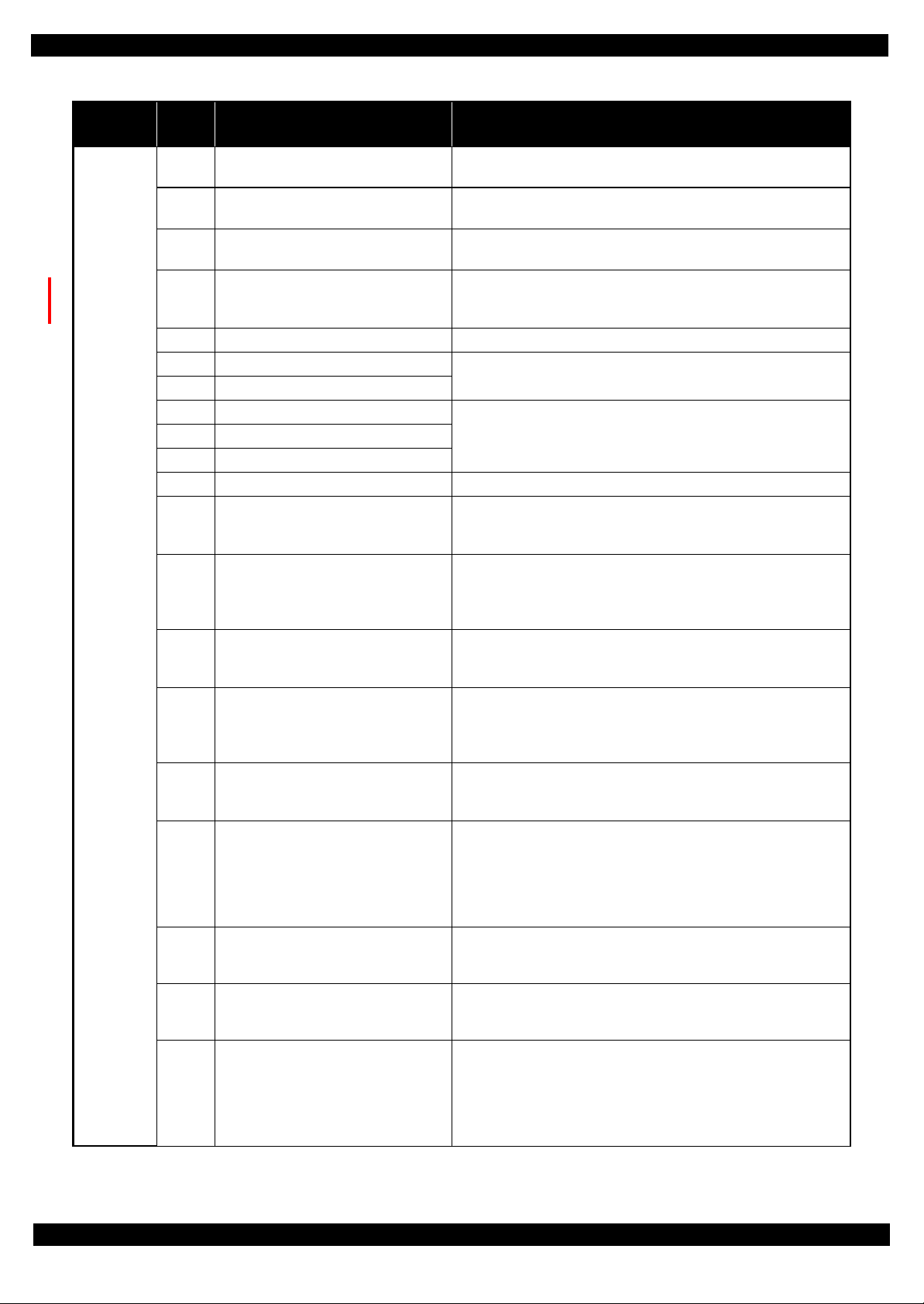
Buffer
Top view
Buffer
Top view
Buffer
Before the ink pressure release
(The Buffer is inflated condition)
After the ink pressure release
(The Buffer is deflated condition)
Ink Supply Unit
Print head
When separating the Printhead and the Ink Supply Unit, make sure to perform "3.2.5
Ink Leak Check (p74)" to check if ink is leaking.
After disconnecting the Printhead and the Ink Supply Unit, ink may spill over even if the
pressure is released. Therefore, be careful not to contaminate the surroundings.
Make sure that the buffer is being deflated before the print head is removed, as shown
below.
If the buffer is inflated, make sure to perform the “Ink pressure release” again, because
the ink is not discharged condition.
Figure 2-2. The buffer condition before and after performing the ink pressure release
Printer cannot perform Ink Pressure Release when Printer is error condition.
Therefore, when Printer cannot perform Ink Press ure Release by fatal error, Perform
the repair operation by the "Repair operation of Print Head and Ink Supply Unit (When
the Printer cannot perform the Ink Pressure Release by fatal error) (p31)".
Disassembly/Reassembly Disassembly/Reassembly Procedures 29
Confidential
Page 30

Epson WF-M5690/M5190 series Revision B
Table 2-3. Consumption amount of maintenance box by each menu
Menu Consumption(%) Remarks
Cleaning CL1 0.5%
CL2 2.0%
CL3 4.0%
Strong Cleaning A 18.0% Special Sequential menu
(Not count consumption of maintenance box)
Strong Cleaning B 35.0%
Special Sequential menu
(Not count consumption of maintenance box)
Ink Charge 45.0%
Ink Pressure Release 5.0%
Special Sequential menu
(Not count consumption of maintenance box)
This product has special sequential menu like the ink pressure release, and this menu is
not count the consumption of maintenance box.
When you execute the these menu, confirm that the remaining amount of maintenance
box is sufficient by referring the following table.
Disassembly/Reassembly Disassembly/Reassembly Procedures 30
Confidential
Page 31

Epson WF-M5690/M5190 series Revision B
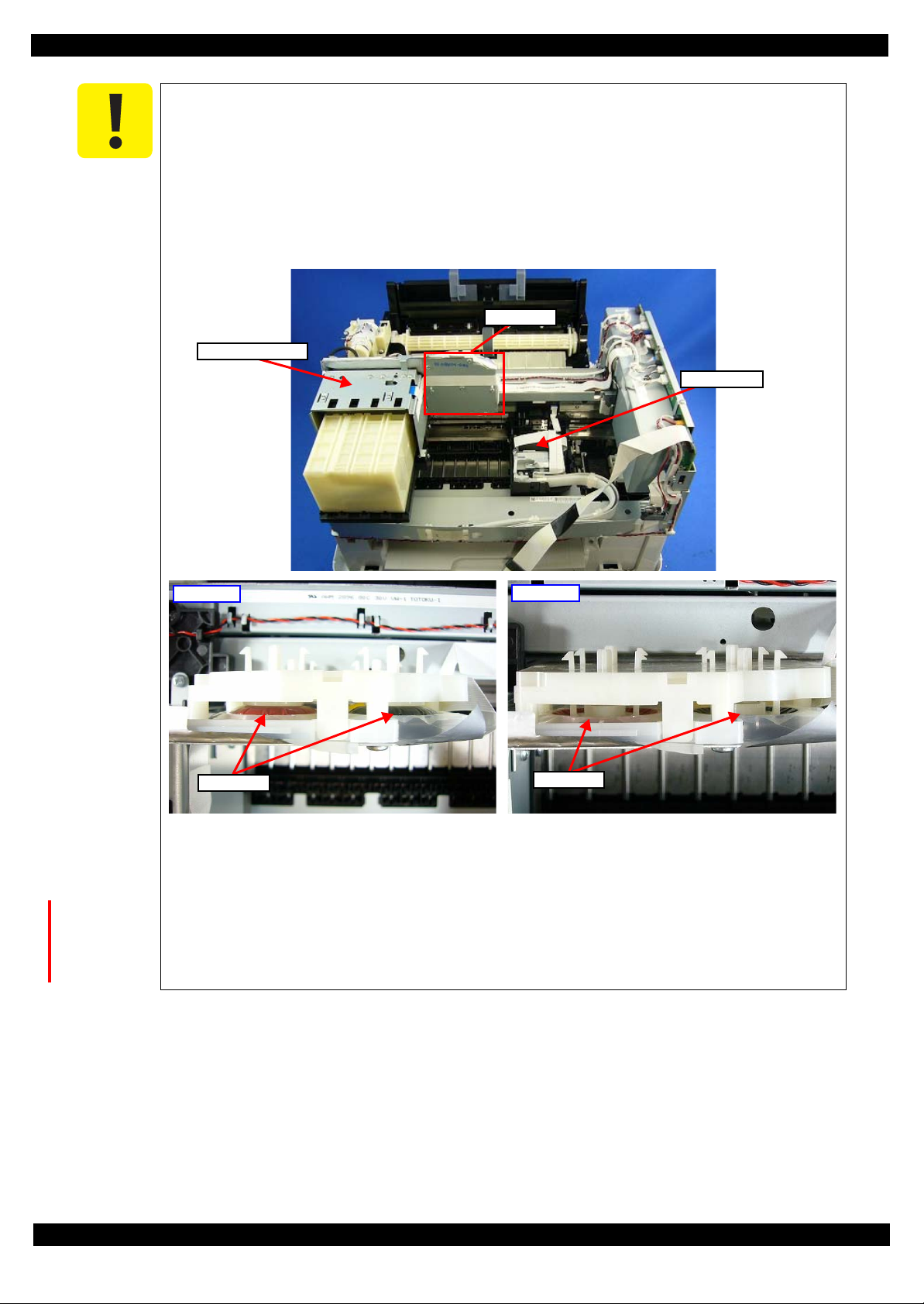
Ink Tube
Tube Clip
Repair operation of Print Head and Ink Supply Unit
(When the Printer cannot perform the Ink Pressure Release by fatal error)
1. Remove the "Ink System Supply Assy (Ink Supply Unit w/ Printhead) (p45)".
2. Clip the Ink tube by the Tube Clip like the following figure.
Make sure to put down plastic sheet or cloth, because ink may drop from connector of Ink
Tube and Print Head.
Figure 2-3. Replacing Print Head and Ink Supply Unit when Ink Pressure Release can not performed.
3. Remove the two screws, and remove the Ink Tube from the Print Head.
Make sure not to adhere the ink to the connector of the Print Head, because ink may drop
when removing the Ink Tube from Print Head.
Disassembly/Reassembly Disassembly/Reassembly Procedures 31
Confidential
Page 32

Epson WF-M5690/M5190 series Revision B
2.2.2 Parts/Units Need to be Removed in Advance
In Chapter 2 "Disassembly Flowchart (p33)", the procedures are indicated on the premise that some parts/units
are removed in advance. Make sure to remove the following parts/units before starting disassembly.
Ink Cartridges (x4) Maintenance Box
Cassette Assy 1st Duplex Unit
Cassette Assy 2nd
*
Note "*": When the optional Cassette Assy 2nd is installed for WF-M5690/M5190 series.
Disassembly/Reassembly Disassembly/Reassembly Procedures 32
Confidential
Page 33

Epson WF-M5690/M5190 series Revision B
2.2.3 Disassembly Flowchart
This section describes procedures for disassembling the parts/units in a flowchart format. For some parts/units,
detailed procedures or precautions are provided (accordingly indicated by icons and cell's color). Refer to the
explanations in the example chart below and perform an appropriate disassembling and assembling procedure.
(See "2.3 Detailed Disassembly/Reassembly Procedure for each Part/Unit (p41)" .)
For routing cables, see "2.4 Routing FFCs/Cables (p49)".
2.2.3.1 Parts/Units whose Configuration is Different between Models in the Flowchart
The models describe in this manual employ the same printer mechanism but they have different printing related
functions and structures. Therefore, the parts/units vary and the shape of them differs even they have the same
parts name.
In the flowchart in this section, the parts are in two colors: black for the common parts or units, and blue for the
parts or units which differ between models. For the parts or units which differ between models, confirm the
composition of the parts for the printer whose disassembly procedure you want to check, and then see the
disassembly flowchart.
Table 2-4. Parts/Units whose Configuration is Different between Models
Model Name Exterior Parts
WF-M5690 series "Scanner Unit (p36)"
"ADF Unit (p36)"
"ADF Cover Assy (p36)"
• "ADF Cover Housing
Upper (p36)"
• "LD Cover (p36)"
• "LD Shaft (p36)"
• "Extension Spring 0.99
(p36)"
• "ADF LD Assy (p36)"
"ADF Rear Cover (p36)"
"ADF Document Support
Assy (p36)"
"ADF Pad Assy (p35)"
"FAX Cover (p35)"
WF-M5190 series "Housing Upper Assy (p35)"
"USB Cover (p35)"
Main Board
Related Parts
"Interface Board Assy
(p38)"
"Interface Board Shield
Plate Upper (p38) "
"Interface Board (p38)"
"Interface Board Shield
Plate Lower (p38) "
---
Control Panel
Components
"Panel Assy (p35)"
"Panel Assy (p35)"
Disassembly/Reassembly Disassembly/Reassembly Procedures 33
Confidential
Page 34

Epson WF-M5690/M5190 series Revision B
USB Cover
1
2
(p 68) (p 77)
Ink System Unit
1
1
(p 71)
Ref.
Item Description Reference
Parts/unit name
White-letter Part/unit supplied as an ASP --Black-letter Part/unit not supplied as an ASP ---
Icon
Indicates a practice or condition that could result in
injury or loss of life if not strictly observed.
Indicates the reference
page in blue-letter
Indicates a practice or condition that could result in
damage to, or destruction of equipment if not strictly
observed.
Indicates the reference
page in blue-letter
Indicates the parts that are inevitably broken in the
disassembling procedure, and should be replaced with
a new one for reassembly.
---
Indicates necessary check items in the disassembling/
assembling procedure.
Indicates the reference
page in blue-letter
Indicates supplementary explanation for disassembly
is given.
Indicates the reference
page in blue-letter
Indicates particular tasks to keep quality of the units
are required.
Indicates the reference
page in blue-letter
Indicates particular routing of cables is required.
Indicates the reference
page in blue-letter
Indicates particular adjustment(s) is/are required.
Chapter 3 "Adjustment
(p53)"
Indicates lubrication is required.
Chapter 4 "Maintenance
(p89)"
Indicates the number of screws securing the parts/
units.
---
Indicates the points secured with other than a screw
such as a hook, rib, dowel or the like.
---
Shows removal/installation
as a unit/assy. is available.
Reference page
Shows the screw types and
the specified torque in the
“Screw type/torque list”.
Explanation available in the
Reference Guide
White letters indicate a part/
unit supplied as an ASP.
Black letters indicate a part/
unit not supplied as an ASP.
The example below shows how to see the charts on the following pages.
S4
S3
Disassembly/Reassembly Disassembly/Reassembly Procedures 34
Confidential
Page 35

Epson WF-M5690/M5190 series Revision B
S1
S2
S3
S4
S5
S6S7S8
S9
S10
S11
S12
S13
S14
S15
S16
S17
S18
S19
S2
S2
S2
S2
S2
S3
S7
2.2.3.2 Exterior Parts
START
WF-M5190 series WF-M5690 series
Panel Assy
(p 42)
Panel Assy
---
9
S3
(p 42)
1
7
Paper Stopper
Assy
(p 48)
2
---
Metal Plate
(w/ Paper
Stopper Assy)
S3
(p 49)
Cover ASF Assy
6
---
---
---
2
ADF Pad Assy
---
4
(p 48)
Housing Rear
Assy
4
2
(p 41)
Panel FFC
WF-M5190 series WF-M5690 series
Go to the next step
Housing Rear
Assy
FAX Cover
WF-M5190 series WF-M5690 series
Housing Upper
Assy
ADF Unit /
Scanner Unit
5
---
(p 41)
S2
(p 47) (p 49)
Front Housing
Assy
3
S2
(p 41)
2
WF-M5190 series WF-M5690 series
Housing Rear
Assy
Go to the next step
USB Cover
A
(p 37)
Speaker /
Speaker Holder
(p 41)
Paper Support
Pickup Assy 1st
Cover ASF Front
Cover ASF Rear
---
---
2
---
---
2
---
---
---
2
---
WF-M5190 series
2
USB Cover
S2
(p 41)
---
WF-M5690 series
FAX Cover
2
4
(p 41) (p 49)
2
4
2
Rear Housing
---
Common parts/units
Parts/units whose
composition or shape
---
---
differ between models
7
2
2
(p 36)
Screw type/torque list
Symbol Screw Type Torque
C.B.P-TITE SCREW 2x6-F/ZN-3C 2 1 kgf·cm
C.B.P-TITE SCREW 3x10-F/ZN-3C 6 1 kgf·cm
Stacker Assy
---
4
---
C.B.S-TITE SCREW 3x6-F/ZN-3C 6
1 kgf·cm
C.P.SCREW 3x6-F/ZN-3C 6 1 kgf·cm
C.P.SCREW 3x6-F/ZN-3C 2
5 kgf·cm
C.B.P-TITE (P2) SCREW 3x10-F/ZN-3C 6 1 kgf·cm
C.B.P-TITE SCREW 3x8-F/ZN-3C 6
1 kgf·cm
C.P.SCREW 2.5x6-F/ZN-3C 2 5 kgf·cm
C.P.SCREW 3x5-F/ZN-3C 6
1 kgf·cm
C.B.S-TITE (P4) SCREW 3x8-F/ZN-3C 6 1 kgf·cm
The removed parts/units differ between models when the name of each model is indicated and
enclosed in a box. If “Go to the next step” is indicated for a specific model in the box, skip the
step for the model and go to the next step.
This flowchart is made on the premise that the parts/units instructed in "2.2.2 Parts/Units Need
to be Removed in Advance (p32)" are already removed in advance.
See "2.2.3.4 Printhead/Ink Supply Unit (p39)" for disassembly of the Printhead and Ink Supply
Unit.
See "2.2.3.5 2nd Cassette Unit (p40)" for disassembly of the 2nd Cassette Unit.
C.B.P-TITE SCREW 2.5x8-F/ZN-3C 6
C.B.P-TITE SCREW 2x10-F/ZN-3C 3 0.5 kgf·cm
C.B.P-TITE (S-P1) SCREW 3x12-F/ZN-3C 6
C.B.S-TITE (P4) SCREW 3x10-F/ZN-3C 6 1 kgf·cm
C.P.SCREW 3x4-F/ZN-3C 6
C.B.EP-TITE SCREW 2.6x17 (B=14) F/ZN-3C 2.5 0.4 kgf·cm
P.W.,2.8x0.5x6.5-F/ZN-3C 3
C.P.SCREW 2.5x6-F/ZN-3C 6 1 kgf·cm
C.B.S-TITE(P2) SCREW,3x8-F/ZB-3C 6
1 kgf·cm
1 kgf·cm
1 kgf·cm
0.5 kgf·cm
1 kgf·cm
Flowchart 2-1. Disassembling Flowchart of Exterior Parts (1)
Disassembly/Reassembly 35
Confidential
Page 36

Epson WF-M5690/M5190 series Revision B
S2
S2
S1
S2
S3
S4
S5
S6
S7
S8
S9
S10
S11
S12
S13
S14
S15
S16
S17
S18
S19
(p 35)
2
ADF Unit
(p 48) (p 49)
---
Scanner Unit
---
2
(p 49)
---
ADF Rear Cover
1
S2
(p 48)
ADF Cover Assy
(p 48)
3
LD Shaft
---
2
---
---
1
ADF Document
Support Assy
(p 48)
ADF Cover
Housing Upper
---
2
(p 47)
4
5
LD Cover
1
---
Extension Spring
0.99
---
ADF LD Assy
---
---
Screw type/torque list
Symbol Screw Type Torque
C.B.P-TITE SCREW 2x6-F/ZN-3C 2 1 kgf·cm
C.B.P-TITE SCREW 3x10-F/ZN-3C 6 1 kgf·cm
C.B.S-TITE SCREW 3x6-F/ZN-3C 6
1 kgf·cm
C.P.SCREW 3x6-F/ZN-3C 6 1 kgf·cm
C.P.SCREW 3x6-F/ZN-3C 2
---
2
C.B.P-TITE (P2) SCREW 3x10-F/ZN-3C 6 1 kgf·cm
C.B.P-TITE SCREW 3x8-F/ZN-3C 6
5 kgf·cm
1 kgf·cm
C.P.SCREW 2.5x6-F/ZN-3C 2 5 kgf·cm
---
---
C.P.SCREW 3x5-F/ZN-3C 6
1 kgf·cm
C.B.S-TITE (P4) SCREW 3x8-F/ZN-3C 6 1 kgf·cm
C.B.P-TITE SCREW 2.5x8-F/ZN-3C 6
1 kgf·cm
C.B.P-TITE SCREW 2x10-F/ZN-3C 3 0.5 kgf·cm
C.B.P-TITE (S-P1) SCREW 3x12-F/ZN-3C 6
1 kgf·cm
C.B.S-TITE (P4) SCREW 3x10-F/ZN-3C 6 1 kgf·cm
1 kgf·cm
0.5 kgf·cm
1 kgf·cm
Common parts/units
Parts/units whose
composition or shape
differ between models
C.P.SCREW 3x4-F/ZN-3C 6
C.B.EP-TITE SCREW 2.6x17 (B=14) F/ZN-3C 2.5 0.4 kgf·cm
P.W.,2.8x0.5x6.5-F/ZN-3C 3
C.P.SCREW 2.5x6-F/ZN-3C 6 1 kgf·cm
C.B.S-TITE(P2) SCREW,3x8-F/ZB-3C 6
Flowchart 2-2. Disassembling Flowchart of Exterior Parts (2)
Disassembly/Reassembly 36
Confidential
Page 37

Epson WF-M5690/M5190 series Revision B
S2
S2
S3
S14
2.2.3.3 Printer Mechanism
A
Middle Housing
(p 41)
Main Board Unit
S3
(p 42)
(p 51) (p 53)
Decompress Pump
Unit
CR Cover
Ink Supply Unit
Grounding Plate
Ink Supply Unit/
Printhead
(p 38)
C
(p 35)
The removed parts/units differ between models when the name of each model is indicated and
enclosed in a box. If “Go to the next step” is indicated for a specific model in the box, skip the
step for the model and go to the next step.
See "2.2.3.4 Printhead/Ink Supply Unit (p39)" for disassembly of the Printhead and Ink Supply
Unit.
4
---
CSIC FFC
3
3
3
(p 38)
(p 50)
---
---
Rear ASF Assy
S2
(p 46) (p 53)
4
---
Rear ASF Guide
Upper Assy
Ink System Unit
S2
(p 43) (p 50)
Option
Connector
---
CR Scale /
Extension Spring
2.03
Maintenance Box
Ink Eject Joint
2
1
---
2
---
Housing Rear
Assy
---
USB Cover
S2
(p 46) (p 50)
ASF Drive Change
Lever Assy
2
---
Shaft drive
pick up
---
2
1
2
---
1
ASF Drive Change
---
---
---
(p 46) (p 53)
Spur Gear 11.2
---
---
---
Compound Gear
16,10.4
---
---
---
Metal Plate Left
(p 44) (p 49)
PF Encoder
PF Encoder FFC
Lever Holder
---
S3
S11
(p 44)
(p 49)
---
---
3
---
1
2
---
---
Spur Gear 11.2
---
PF Tension
Stopper Holder
S10
(p 53)
PF Timing Belt
(p 44) (p 53)
---
---
1
---
---
---
Extension Spring
0.63
---
Decompress
Pump Unit
S6S3
(p 47) (p 50)
---
Power Supply
Unit
S3
S2
(p 47)
(p 50) (p 53)
---
Screw type/torque list
Symbol Screw Type Torque
S1
S2
S3
S4
S5
S6
---
---
S7
S8
S9
S10
S11
S12
S13
S14
S15
S16
S17
S18
S19
4
2
C.B.P-TITE SCREW 2x6-F/ZN-3C 2 1 kgf·cm
C.B.P-TITE SCREW 3x10-F/ZN-3C 6 1 kgf·cm
C.B.S-TITE SCREW 3x6-F/ZN-3C 6
C.P.SCREW 3x6-F/ZN-3C 6 1 kgf·cm
C.P.SCREW 3x6-F/ZN-3C 2
C.B.P-TITE (P2) SCREW 3x10-F/ZN-3C 6 1 kgf·cm
C.B.P-TITE SCREW 3x8-F/ZN-3C 6
C.P.SCREW 2.5x6-F/ZN-3C 2 5 kgf·cm
C.P.SCREW 3x5-F/ZN-3C 6
C.B.S-TITE (P4) SCREW 3x8-F/ZN-3C 6 1 kgf·cm
C.B.P-TITE SCREW 2.5x8-F/ZN-3C 6
C.B.P-TITE SCREW 2x10-F/ZN-3C 3 0.5 kgf·cm
C.B.P-TITE (S-P1) SCREW 3x12-F/ZN-3C 6
C.B.S-TITE (P4) SCREW 3x10-F/ZN-3C 6 1 kgf·cm
C.P.SCREW 3x4-F/ZN-3C 6
C.B.EP-TITE SCREW 2.6x17 (B=14) F/ZN-3C 2.5 0.4 kgf·cm
P.W.,2.8x0.5x6.5-F/ZN-3C 3
C.P.SCREW 2.5x6-F/ZN-3C 6 1 kgf·cm
C.B.S-TITE(P2) SCREW,3x8-F/ZB-3C 6
Wireless LAN
Module
---
B
3
---
(p 38)
Common parts/units
Parts/units whose
composition or shape
differ between models
1 kgf·cm
5 kgf·cm
1 kgf·cm
1 kgf·cm
1 kgf·cm
1 kgf·cm
1 kgf·cm
0.5 kgf·cm
1 kgf·cm
Flowchart 2-1. Disassembling Flowchart of Printer Mechanism (1)
Disassembly/Reassembly 37
Confidential
Page 38

Epson WF-M5690/M5190 series Revision B
S2
S5
S3
S3
S4
S8
S3
(p 37)
B
CR Cover
(p 41)
Ink Supply Unit
Grounding Plate
Ink System Supply
Assy
S19S17
S3
(p 45) (p 50)
---
Decompress Pump
Unit
Power Supply
Unit
Fasten Plate
Center
S3
(p 50)
---
Metal Plate Left
Fasten Plate Left
S2
(p 50)
---
---
8
3
2
(p 37)
C
(p 37)
Ink Supply Unit
Grounding Plate
2
3
S3
(p 44)
Head FFC
2
*1
---
Power Supply
Unit
Rear ASF Assy
Rear ASF Guide
Upper Assy
Stacker Assy
Ink System Unit
ASF Drive Change
Lever Assy
Metal Plate Left
Front Frame Assy
S3
(p 44) (p 49)
(p 53)
---
Star Wheel Assy
2
S2
5
(p 47) (p 53)
2
PF Tension
Stopper Holder
PF Timing Belt
8
(p 44) (p 51)
*1 If you find it difficult to
connect the Head FFC to the
Printhead when connecting
it, it will make the procedure
easier to remove the
Printhead and the Ink Supply
Unit together without
disconnecting the joint
section. However, once the
Printhead is removed from
the Carriage Assy,
performing "Checking the
Platen Gap (p73)" is
necessary.
Frame Base Assy
(p 50) (p 53)
(p 89)
---
---
Fasten Plate
Center
Fasten Plate Left
Metal Plate Left
CR Scale/
Extension Spring
3.23
Driven Pulley
Assy
Support Plate
Right/Left
Main Frame
Mounting Plate
S3
---
Support Plate
Right/Left
EJ Roller
1
2
(p 47)
(p 53) (p 89)
---
1
2
4
CR Guide Frame
---
(w/ Carriage Assy)
5
---
CR Guide Frame
---
---
(p 89) (p 53)
Carriage Assy
(p 46) (p 89)
(p 53)
---
---
5
6
Paper Guide
Upper
(p 53)
---
6
PE Lever Holder
Assy
S3
(p 53)
1
---
Driven Pulley
Assy
(p 89)
CR Motor
S15
(p 50) (p 53)
---
---
---
S3
(p 53)
Main Board
Assembly Board
Main Frame Assy
S3
(p 44) (p 50)
(p 53) (p 89)
2
3
Main Board Cable
Holder
(p 51)
Shield Plate
Holder
S3
---
Main Board
Shield Plate Upper
Assy
S17S15
S3
(p 42)
Main Board
(p 43)
Main Board
Shield Plate
Lower Assy
(p 43)
Common parts/units
Parts/units whose
composition or shape
differ between models
Interface Board
Assy
---
3
S3
(p 43)
---
3
Main Board
Shield Plate Upper
---
3
---
---
3
Interface Board
Shield Plate Upper
(p 43)
Interface Board
---
Interface Board
Shield Plate
3
---
---
---
Lower
7
3
---
3
---
---
---
Screw type/torque list
Symbol Screw Type Torque
S1
C.B.P-TITE SCREW 2x6-F/ZN-3C 2 1 kgf·cm
S2
C.B.P-TITE SCREW 3x10-F/ZN-3C 6 1 kgf·cm
S3
C.B.S-TITE SCREW 3x6-F/ZN-3C 6
S4
C.P.SCREW 3x6-F/ZN-3C 6 1 kgf·cm
S5
C.P.SCREW 3x6-F/ZN-3C 2
S6
C.B.P-TITE (P2) SCREW 3x10-F/ZN-3C 6 1 kgf·cm
S7
C.B.P-TITE SCREW 3x8-F/ZN-3C 6
S8
C.P.SCREW 2.5x6-F/ZN-3C 2 5 kgf·cm
S9
C.P.SCREW 3x5-F/ZN-3C 6
S10
C.B.S-TITE (P4) SCREW 3x8-F/ZN-3C 6 1 kgf·cm
S11
C.B.P-TITE SCREW 2.5x8-F/ZN-3C 6
S12
C.B.P-TITE SCREW 2x10-F/ZN-3C 3 0.5 kgf·cm
S13
C.B.P-TITE (S-P1) SCREW 3x12-F/ZN-3C 6
S14
C.B.S-TITE (P4) SCREW 3x10-F/ZN-3C 6 1 kgf·cm
S15
C.P.SCREW 3x4-F/ZN-3C 6
S16
C.B.EP-TITE SCREW 2.6x17 (B=14) F/ZN-3C 2.5 0.4 kgf·cm
S17
P.W.,2.8x0.5x6.5-F/ZN-3C 3
S18
C.P.SCREW 2.5x6-F/ZN-3C 6 1 kgf·cm
S19
C.B.S-TITE(P2) SCREW,3x8-F/ZB-3C 6
---
---
1 kgf·cm
5 kgf·cm
1 kgf·cm
1 kgf·cm
1 kgf·cm
1 kgf·cm
1 kgf·cm
0.5 kgf·cm
1 kgf·cm
Flowchart 2-2. Disassembling Flowchart of Printer Mechanism (2)
Disassembly/Reassembly 38
Confidential
Page 39

Epson WF-M5690/M5190 series Revision B
S2
S16
S3
S16
S3
S2
2.2.3.4 Printhead/Ink Supply Unit
The disassembling and reassembling procedure of the Printhead/Ink Supply Unit requires additional steps before and during the procedure. Therefore, the whole flow from disassembling to reassembling is provided below.
Note: The black arrows ( ) indicate disassembling, and the red arrows ( ) show reassembling.
Printhead / Ink Supply Unit START
Releasing the pressure
(p 28)
WF-M5190 series WF-M5690 series
Panel Assy
Panel Assy
---
9
(p 42)
(p 42)
Panel FFC
WF-M5190 series
Go to the next step
WF-M5690 series
Housing Rear
Assy
FAX Cover
WF-M5190 series
Housing Rear
Assy
WF-M5690 series
Go to the next step
Checking the platen gap
(p 73)
USB Cover
Ink leak check
(p 88)
1
7
Middle Housing
Head angular mecha adjustment
(p 65)
4
---
Reassemble the printer and perform the
(p 41)
required adjustment
(p 54)
.
CR Cover
---
3
(p 41)
Common parts/units
Parts/units whose
composition or shape
differ between models
WF-M5190 series WF-M5690 series
Housing Upper
Assy
ADF Unit/
Scanner Unit
5
(p 41)
---
Front Housing
Assy
S2
(p 47) (p 49)
3
S2
(p 41)
2
Screw type/torque list
Ink Supply Unit
Grounding Plate
2
S3
(p 44)
2
7
S3
2
Decompress Pump
Unit
Printhead
S12 S16S17
(p 46)
(p 51) (p 53)
6
---
Ink Supply Unit
6
S3
S16S19
(p 45)
(p 50) (p 53)
---
Symbol Screw Type Torque
S1
C.B.P-TITE SCREW 2x6-F/ZN-3C 2 1 kgf·cm
S2
C.B.P-TITE SCREW 3x10-F/ZN-3C 6 1 kgf·cm
S3
C.B.S-TITE SCREW 3x6-F/ZN-3C 6
S4
C.P.SCREW 3x6-F/ZN-3C 6 1 kgf·cm
S5
C.P.SCREW 3x6-F/ZN-3C 2
S6
C.B.P-TITE (P2) SCREW 3x10-F/ZN-3C 6 1 kgf·cm
S7
C.B.P-TITE SCREW 3x8-F/ZN-3C 6
S8
C.P.SCREW 2.5x6-F/ZN-3C 2 5 kg f·cm
S9
C.P.SCREW 3x5-F/ZN-3C 6
S10
C.B.S-TITE (P4) SCREW 3x8-F/ZN-3C 6 1 kgf·cm
S11
C.B.P-TITE SCREW 2.5x8-F/ZN-3C 6
S12
C.B.P-TITE SCREW 2x10-F/ZN-3C 3 0.5 kgf·cm
S13
C.B.P-TITE (S-P1) SCREW 3x12-F/ZN-3C 6
S14
C.B.S-TITE (P4) SCREW 3x10-F/ZN-3C 6 1 kgf·cm
S15
C.P.SCREW 3x4-F/ZN-3C 6
S16
C.B.EP-TITE SCREW 2.6x17 (B=14) F/ZN-3C 2.5 0.4 kgf·cm
S17
P.W.,2.8x0.5x6.5-F/ZN-3C 3
S18
C.P.SCREW 2.5x6-F/ZN-3C 6 1 kg f·cm
S19
C.B.S-TITE(P2) SCREW,3x8-F/ZB-3C 6
1 kgf·cm
5 kgf·cm
1 kgf·cm
1 kgf·cm
1 kgf·cm
1 kgf·cm
1 kgf·cm
0.5 kgf·cm
1 kgf·cm
Flowchart 2-1. Disassembling Flowchart of Printhead/Ink Supply Unit
Disassembly/Reassembly 39
Confidential
Page 40

Epson WF-M5690/M5190 series Revision B
S2
S2
S2
S2
2.2.3.5 2nd Cassette Unit
2nd Cassette Unit START
Cassette Assy
2nd
---
---
(p 89)
Cassette Cover
---
---
---
2nd Cassette
Cover Left
(p 48)
2nd Cassette
Cover Right
4
3
(p 48)
2nd Cassette
Housing Assy
4
3
2nd Cassette
Cover Front
---
Paper Stopper
Assy
2
---
S7
(p 48)
2
---
---
Screw type/torque list
---
(p 52)
Frame Pickup
Assy
(p 48) (p 52)
4
---
Pickup Assy 2nd
---
1
---
Symbol Screw Type Torque
S1
C.B.P-TITE SCREW 2x6-F/ZN-3C 2 1 kgf·cm
S2
C.B.P-TITE SCREW 3x10-F/ZN-3C 6 1 kgf·cm
S3
C.B.S-TITE SCREW 3x6-F/ZN-3C 6
S4
C.P.SCREW 3x6-F/ZN-3C 6 1 kgf·cm
S5
C.P.SCREW 3x6-F/ZN-3C 2
S6
C.B.P-TITE (P2) SCREW 3x10-F/ZN-3C 6 1 kgf·cm
S7
C.B.P-TITE SCREW 3x8-F/ZN-3C 6
S8
C.P.SCREW 2.5x6-F/ZN-3C 2 5 kgf·cm
S9
C.P.SCREW 3x5-F/ZN-3C 6
S10
C.B.S-TITE (P4) SCREW 3x8-F/ZN-3C 6 1 kgf·cm
S11
C.B.P-TITE SCREW 2.5x8-F/ZN-3C 6
S12
C.B.P-TITE SCREW 2x10-F/ZN-3C 3 0.5 kgf·cm
S13
C.B.P-TITE (S-P1) SCREW 3x12-F/ZN-3C 6
S14
C.B.S-TITE (P4) SCREW 3x10-F/ZN-3C 6 1 kgf·cm
S15
C.P.SCREW 3x4-F/ZN-3C 6
S16
C.B.EP-TITE SCREW 2x16 (B=10) F/ZN-3C 2.5 0.4 kgf·cm
S17
P.W.,2.8x0.5x6.5-F/ZN-3C 3
S18
C.P.SCREW 2.5x6-F/ZN-3C 6 1 kgf·cm
S19
C.B.S-TITE(P2) SCREW,3x8-F/ZB-3C 6
1 kgf·cm
5 kgf·cm
1 kgf·cm
1 kgf·cm
1 kgf·cm
1 kgf·cm
1 kgf·cm
0.5 kgf·cm
1 kgf·cm
Flowchart 2-1. Disassembling Flowchart of 2nd Cassette Unit
Disassembly/Reassembly 40
Confidential
Page 41

Epson WF-M5690/M5190 series Revision B
Rib A
C.B.P-TITE SCREW 3x10 F/ZN-3C (6 ± 1 kgf·cm)
FAX Cover/
USB Cover
Rear right
Rear left
C.B.P-TITE SCREW 3x10 F/ZN-3C (6 ± 1 kgf·cm)
Housing Upper Assy
Rib B
Hook
Inside Front Cover
Front Cover
Front Cover
Rib A
C.B.P-TITE SCREW 3x10 F/ZN-3C (6 ± 1 kgf·cm)
Cross-section
Middle Housing
Rib A
Front
Housing Assy
Bottom left
Hook
Bottom right
Hook
Front
Housing Assy
Middle Housing
C.B.P-TITE SCREW 3x10 F/ZN-3C (6 ± 1 kgf·cm)
Rear left
Ribs of Frame Base
Rear right
Ribs of Frame Base
Housing Rear Assy
C.B.P-TITE SCREW 3x10 F/ZN-3C (6 ± 1 kgf·cm)
Rear left
Rear right
Hook
Right side of Carriage Assy
Carriage Assy
CR Cover
2.3 Detailed Disassembly/Reassembly Procedure for each Part/Unit
FAX Cover/USB Cover
The name and the shape of this part differ, but the disassembly
procedure for this part is the same. The names are FAX Cover for
WF-M5690 series and USB Cover for WF-M5190 series.
Remove the FAX Cover/USB Cover by sliding it in the direction of
the arrow shown above carefully not to damage the rib A (x4) that
secure the FAX Cover/USB Cover.
Housing Upper Assy (WF-M5190 series)
The above figure shows the kind and position of the screw.
Front Housing Assy
The structure of the rib A on the Front Housing Assy is as shown in the cross-section above, and it is extremely fragile. Therefore, be careful not to
damage the rib A when removing the Front Housing Assy.
The positions of the rib A (x3) and rib B (x7) of the Front Housing Assy are shown in the figure above.
When releasing the hooks (x2) of the Front Housing Assy, insert a screw driver or the like from the hole on the bottom of the printer and release them.
The above figure shows the kind and position of the screw.
Middle Housing
After reassembling the Middle Housing, make sure the ribs of the Frame Base are aligned and fit in with the Middle Housing without any gap.
Disassembly/Reassembly Detailed Disassembly/Reassembly Procedure for each Part/Unit 41
The above figure shows the kind and position of the screw.
The above figure shows the kind and position of the screw.
Housing Rear Assy
CR Cover
After installing the CR Cover to the Carriage Assy, make sure the
CR Cover is firmly secured with the hooks (x3) shown above.
Confidential
Page 42

Epson WF-M5690/M5190 series Revision B
Hook A
Hook B
Back of Panel Assy
Panel Assy
Bottom left of Scanner Unit
Scanner
Unit
Scanner
Unit
Bottom right of Scanner Unit
Panel Assy
Scanner
Unit
Front
Cover
Hook C
Rib
Panel Assy
Bottom of Panel Assy
Bottom of Housing Upper Assy
Housing Upper Assy
Hook A
Hook B
Rib A
Rib B
Housing Upper Assy
Front
Cover
Panel Assy
Main
Board Unit
Legs
Left
Main Frame
Rib and hole
C.B.S-TITE SCREW 3x6 F/ZN-3C (6 ± 1 kgf·cm)
Main Board Unit
Main Board Unit Bracket Front
Main Board Unit Bracket Rear
Interface Board FCC
C.P.SCREW 3x4 F/ZN-3C (6 ± 1 kgf·cm)
C.P.SCREW 2.5x6 F/ZN-3C (6 ± 1 kgf·cm)
C.B.S-TITE-SCREW 3x6 F/ZN-3C (6 ± 1 kgf·cm)
Main Board Shield Plate
Upper Assy
Panel Assy (WF-M5690 series)
Panel Assy (WF-M5190 series)
When removing the Panel Assy, follow the procedure below.
1. Open the Front Cover, and release the hook A (x2) of the Panel Assy from the bottom of the Scanner Unit.
2. Release the hook B (x5) of the Panel Assy.
3. Lift the Panel Assy in the direction of the arrow and release the ribs (x5) and hook C (x2) on the top of the Panel Assy, and then remove the Panel
Assy.
Main Board Unit
When removing the Panel Assy, follow the procedure below.
1. Open the Front Cover, and release the hook A of the Panel Assy from the bottom of the Housing Upper Assy.
2. Release the hook B (x5) and rib A (x3) of the Panel Assy.
3. Slide the Panel Assy slightly in the direction of the arrow and release the rib B (x2), and remove the Panel Assy.
Main Board Shield Plate Upper Assy
When installing the Main Board Unit, insert the ribs of the Main Board Unit Bracket Front/Main Board Unit Bracket Rear into the holes of the
Main Board Unit.
After installing the Main Board Unit, make sure the legs of the Main Board Unit Grounding Plate touch the Main Frame.
Disassembly/Reassembly Detailed Disassembly/Reassembly Procedure for each Part/Unit 42
The Interface Board FFC is connected to the back of the Main Board Shield Plate Upper Assy, therefore, be careful of it when removing the Main
Board Shield Plate Upper Assy.
The above figure shows the kind and the position of the screw.
Confidential
Page 43

Epson WF-M5690/M5190 series Revision B
Main Board Shield Plate Upper Assy
Interface Board Shield Plate
Interface Board Grounding Plate
Interface Board
Slide the Interface Board Assy, and install it
to the Main Board Shield Plate Upper Assy.
C.B.S-TITE SCREW 3x6 F/ZN-3C (6 ± 1 kgf·cm)
Dowel and hole
2
1
C.P.SCREW 2.5x6 F/ZN-3C (2 ± 5 kgf·cm)
Main Board
Main Board Shield
Plate Lower Assy
C.P.SCREW 3x6 F/ZN-3C (6 ± 1 kgf·cm)
3
Speaker Holder
Speaker
Ink System Unit
1
2
Dowel
Hole
A
B
C
Ink System Unit
D
A BDC
Maintenance
Box Ink Eject
Joint
Frame Base
Ink System
Tube
Tube
clamp
Hole of Frame Base
C.B.P-TITE SCREW 3x10 F/ZN-3C (6 ± 1 kgf·cm)
Groove
Acetate tape
Ink System
Tube
Tube
clamp
Interface Board Assy (WF-M5690 series)
Ink System Unit
When removing the Interface Board Assy, follow the procedure below.
1. Interface Board Shield Plate, Interface Board, Interface Board Grounding Plate are secured with the screws (x3).
2. Aline the dowel of the Main Board Shield Plate with the hole of the Interface Board Assy, and install th e Main Board Shield P late to the Int erface
Board Assy.
3. The above figure shows the kind and position of the screw.
Main Board / Main Board Shield Plate Lower Assy
Speaker/Speaker Holder
(WF-M5690 series)
Tighten the screws in the order indicated in the figure above.
Make sure to transplant the PDL SD Card to new main Board when
replacing the main bo ard.
Disassembly/Reassembly Detailed Disassembly/Reassembly Procedure for each Part/Unit 43
Spin the Speaker Holder in the direction of the arrow of the above
figure, and remove the Speaker and Speaker Holder.
When connecting the Ink System Tube to the Maintenance Box Ink Eject Joint, make sure to insert the end of the tube into the socket on the
Maintenance Box Ink Eject Joint up to the full to its base in order to prevent the waste ink from leaking.
When installing the Ink System Unit, follow the procedure below.
1. Route the Ink System Tube through the hole of the Frame Base.
2. Align the dowels A to dowel E of the Ink System Unit with the hole A to hole E of the Frame Base, and install the Ink System Unit to the Frame Base.
3. Insert the end of the Ink System Tube into the socket on the Maintenance Box Ink Eject Joint to the full up to its base, and secure the tube with
the tube clamp.
4. Route the Ink System Tube through the groove of the Frame Base, and secure it with acetate tape.
5. Tighten the screws (x2) in the order indicated in the figure above to secure the Ink System Unit to the Frame Base.
Confidential
Page 44

Epson WF-M5690/M5190 series Revision B
Step 2
Head FFC Holder
Rib B and hole A
Rib C and cutout
Hook and hole B
Rib A
Front Frame
Rib of Front Frame
Step 1
Head FFC Holder
Head FFC
Front Tube Guide
Tube
Holders
Step 3: Back of Front Frame
Cross-section of
Tube Holder
Front Tube
Guide
Head
FFC
C.B.P-TITE SCREW 2.5x8 F/ZN-3C (6 ± 1 kgf·cm)
PF Encoder
PF Scale
PF Encoder
PF Scale
Cutout
Align cutout with rib
Frame Base Assy
Metal Plate Left
Left
APG Lever
APG Change Lever
Bottom left
Rib
Cutout
3
4
5
Right
1
2
Left
PF Scale Sheet
Bottom right
Rib
Cutout
Hole and rib
Hole and hook
C.B.S-TITE SCREW 3x6 F/ZN-3C (6 ± 1 kgf·cm)
Frame Base Assy
Main Frame Assy
C.B.S-TITE SCREW 3x6 F/ZN-3C (6 ± 1 kgf·cm)
Rib
Ink Supply Unit
Ink Supply Unit
Grounding Plate
Front Frame Assy
Hook
C.B.P-TITE SCREW 3x10 F/ZN-3C (6 ± 1 kgf·cm)
C.B.S-TITE SCREW 3x6 F/ZN-3C (6 ± 1 kgf·cm)
Front Frame Assy
Front
Front Frame Assy
Top
Head FFC
PF Encoder / PF Timing Belt
Metal Plate Left
When installing the Head FFC, follow the procedure below.
1. Fit in the rib of the Front Frame to the space between the rib A (x3).
2. Align the rib B (x3), rib C (x2) and hook of the Head FFC Holder with the hole A (x3), cutouts (x2) and the hole B of the Front Frame, and slide
the Head FFC Holder in the direction of the arrow to secure it to the Front Frame.
3. Insert the Front Tube Guide between the Tube Holder and Head FFC.
Main Frame Assy (w / CR Guide Frame)
When installing the PF Encoder, set the encoder over the PF
Scale with the scale in the slit as shown in the figure above. After
installing PF Encoder, make sure it does not touch the PF Scale.
Install the PF Timing Belt as shown above and make sure the
belt is correctly attached to the gears and pulley.
Ink Supply Unit Grounding Plate
When installing the Metal Plate Left to the Frame Base Assy,
align the cutout of the Metal Plate Left with the rib of the
Frame Base Assy.
Tighten the screws in the order indicated in the figure above.
Front Frame Assy
When installing the Ink Supply Unit Grounding Plate, secure it with
the hook of the Ink Supply Unit and rib of the Front Frame, and
tighten the screws (x2) in the order indicated in the figure above.
Tighten the screws in the order indicated in the figure above.
Confidential
When installing the Main Frame Assy to the Frame Base Assy, make sure of the following.
Disassembly/Reassembly Detailed Disassembly/Reassembly Procedure for each Part/Unit 44
• Align the holes (x2) of the Main Frame Assy with the ribs (x2) of the Frame Base Assy shown above.
• Align the cutout on the bottom of the Main Frame Assy with the rib of the Frame Base Assy.
• Engage the APG Lever with the APG Change Lever properly.
• Align the hook of the PF Scale Sheet with the hole of the Main Frame Assy.
Tighten the screws in the order indicated in the figure above.
Page 45

Epson WF-M5690/M5190 series Revision B
Do not remove.
Section A
P.W.,2.8x0.5x6.5, F/ZN-3C (3 ± 0.5 kgf·cm)
C.B.S-TITE SCREW 3x6 F/ZN-3C (6 ± 1 kgf·cm)
Positioning hole and dowel
Section A
C.B.S-TITE(P2)SCREW 3x8 F/ZB-3C (6 ± 1 kgf·cm)
Cover Joint
End of ink tube
Rubber packing
Holes of Printhead
Joint section
Positioning hole and dowel
I/C Holder Unit
Ink tube
Rubber packing
Tube Holder A
Step 2
Step 1
Tube Spacers
Ink tube
Attachment positions of Tube Holder B
Step 5
Tube Holder B
Carriage Assy
Step 4
C.B.EP-TITE SCREW,2.6x17(B=14),F/ZN-3C (3 ± 0.5 kgf·cm)
C.B.S-TITE SCREW 3x6 F/ZN-3C (6 ± 1 kgf·cm)
C.B.S-TITE(P2)SCREW 3x8 F/ZB-3C (6 ± 1 kgf·cm)
Ink System Supply Assy (Ink Supply Unit w/ Printhead)
When removing/installing the Printhead, move the Carriage Assy to the center of the printer, and place the Spacer (about 5 mm) between the
Carriage Assy and Star Wheel Assy in order to prevent the CR Guide Frame and Main Frame from being deformed. (See " Printhead (p46)".)
To prevent ink leakage, make sure not to separate the ink tubes from the I/C Holder Unit by removing the scre ws (x2) in sectio n A shown above.
Loosening the screws even just once will cause ink leakage, therefore, make sure to replace the Ink System Supply Assy with a new one.
When installing the Ink System Supply Assy, see " Printhead (p46)" and " Ink Supply Unit (p45)".
Ink Supply Unit
Prepare the Ink Supply Unit (Remove the Cover joint)
Before disconnecting the joint section of the Printhead and the ink tubes of the Ink Supply Unit, it is necessary to perform “Ink Pres sure Release”
in advance. Make sure to perform “Ink Pressure Release”, otherwise, the ink in the ink tube will spill over. (See "2.2.1 Caution when Replacing
the Printhead/Ink Supply Unit (p28)".)
When disconnecting the joint section of the ink tubes of the Ink Supply Unit and the Printhead, ink may slightly spill over from the ink tubes
Remove the Cover Joint before installing the ink Supply Unit to Printer.
The Ink Supply Unit has two type Cover Joint.
• Cover Joint is fixed by screw.
• Cover Joint is not fixed by screw.
If Cover Joint is fixed by screw, remove the screw and Cover Joint.
Make sure to put down plastic sheet or cloth, because shipping liquid may drop from Ink Tube when removing the Cover Joint and screw.
If you remove the Cover Joint to an upward direction, Ink Supply Unit and other parts may dirty by dropped shipping liquid from Ink Tube.
Therefore, make sure to remove the Cover Joint to a downward direction.
Disassembly/Reassembly Detailed Disassembly/Reassembly Procedure for each Part/Unit 45
Perform the following operation after removing the Cover Joint and install the Ink Supply Unit to Printer.
• Confirm the shipping liquid is not dropped from Ink Tube.
• Clean the Ink Tube.
even if “Ink Pressure Release” has been performed. To prevent the inside of the printer being made dirty by the spilling ink, make sure to attach
tape at the joint section of the ink tube hen disconnecting the joint section of the ink tube of the ink supply unit and the printhead.
(See " Printhead (p46)".)
When disconnecting the ink tubes from the Printhead, make sure to replace the rubber packing between the ink tubes and the Printhead with a
new one in order to prevent ink leakage.
When connecting the ink tubes to the Printhead, place the Spacer (about 5 mm) between the Carriage Assy and Star Wheel Assy in order to
prevent the CR Guide Frame and Main Frame from being deformed. (See " Printhead (p46)".)
When installing the Ink Supply Unit, follow the procedure below.
1. Align the positioning holes (x2) and dowels (x2) shown above, and tighten the screws (x4) of the I/C Holder Unit in the order indicated in the figure above.
2. Secure the ink tubes with the Tube Holder A (x3).
3. Move the Carriage Assy to the center of the printer.
4. While aligning the Tube Holder C attached on the ink tubes with the groove of the Carriage Assy, insert the joint section on the end of the ink
tubes into the holes of the Printhead, and then secure the end of the ink tubes with the screws (x2).
5. Secure the ink tubes with the Tube Holder B (x3), and then adjust their attachment positions to between the Tube Spacers.
Once you loosen the screws on the joint section of the ink tubes to the Printhead, make sure to perform "3.2.5 Ink Leak Check (p74)".
If printer can not perform Ink Pressure Release by fatal error, refer to repair procedure of " Repair operation of Print Head and Ink Supply Unit
(When the Printer cannot perform the Ink Pressure Release by fatal error) (p31)".
Confidential
Page 46

Epson WF-M5690/M5190 series Revision B
P.W.2.8x0.5x6.5 F/ZN-3C (3 ± 0.5 kgf·cm)
Thickness gauge (5 mm)
3
Printhead
Carriage Assy
Star Wheel Assy
Position for Spacer
(5 mm)
1
2
Frame Base
Assy
Dowel and
positioning hole
C.B.P-TITE SCREW 3x10 F/ZN-3C (6 ± 1 kgf·cm)
Rear ASF
Assy
Rear right
Trigger Lever Clutch Lever
Rear ASF
Assy
Rear left
C.B.P-TITE SCREW 3x10 F/ZN-3C (6 ± 1 kgf·cm)
Rib
Dowel and
positioning hole
Rear ASF Guide Upper Assy
Rear ASF Guide Upper Assy
Step 1
Step 2
Holes of Frame Driven Assy
Black mark
Carriage Assy
Slit of CR
Encoder
CR Scale
Carriage Assy
Bottom
APG Slider
Rear
APG Slider
Carriage Assy
CR Guide Frame
Printhead
Rear ASF Assy
When installing the Rear ASF Assy to the Frame Base Assy,
move the Trigger Lever in the direction of the arrow to prevent
it from touching the Clutch Lever, and align the positioning
holes (x2) of the Rear ASF Assy with the dowels (x2) of the
Frame Base Assy.
Tighten the screws in the order indicated in the figure above.
Rear ASF Guide Upper Assy
When installing the Rear ASF Guide Upper Assy, follow the
procedure below.
1. Insert the ribs (x2) on the 80-digit side of the Rear ASF Guide
Upper Assy into the holes (x2) of the Frame Driven Assy.
2. Align the positioning hole on the 0-digit side of the Rear ASF
Guide Upper Assy with the dowel of the Frame Base Assy, and
secure the Rear ASF Guide Upper Assy with the screw.
CR Scale
Carriage Assy
To replace the Printhead, it is necessary to disconnect the joint section of the Printhead and the ink tubes of the Ink Supply Unit. Before
disconnecting the joint section, perform “Ink Pressure Release” in advance. (See "2.2.1 Caution when Replacing the Printhead/Ink Supply Unit
(p28)" and " Ink Supply Unit (p45)".)
When disconnecting the joint section of the ink tubes of the Ink Supply Unit and the Printhead, ink may slightly spill over from the ink tubes
even if “Ink Pressure Release” has been performed. To prevent the inside of the printer being made dirty by the spilling ink, make sure to attach
tape at the joint section of the ink tube when disconnecting the joint section of the ink tube of the Ink Supply Unit and the Printhead.
(See " Ink Supply Unit (p45)".)
When disconnecting the ink tubes from the Printhead, make sure to replace the rubber packing between the ink tubes and the Printhead with a
new one in order to prevent ink leakage.
When removing/installing the Printhead, move the Carriage Assy to the center of the printer, and place the Spacer (about 5 mm) between the
Carriage Assy and Star Wheel Assy in order to prevent the CR Guide Frame and Main Frame from being deformed.
Tighten the screws in the order indicated in the figure above.
After installing the Printhead, make sure to connect the ink tubes to the Printhead. (See " Ink Supply Unit (p45)".)
When replacing the Printhead, make sure to perform "3.2.3 PG Adjustment (p65)" and "3.2.5 Ink Leak Check (p74)".
If printer can not perform Ink Pressure Release by fatal error, refer to repair procedure of " Repair operation of Print Head and Ink Supply Unit
(When the Printer cannot perform the Ink Pressure Release by fatal error) (p31)".
Disassembly/Reassembly Detailed Disassembly/Reassembly Procedure for each Part/Unit 46
Install the CR Scale with the black mark section up.
Make sure to put the CR Scale through the slit of the CR
Encoder.
Before installing the Carriage Assy to the CR Guide Frame, make
sure the APG Slider is correctly installed to the Carriage Assy as
shown above.
Confidential
Page 47

Epson WF-M5690/M5190 series Revision B
1
2
C.B.P-TITE(S-P1) SCREW 3x12 F/ZN-3C (6 ± 1 kgf·cm)
Paper Guide Front Assy Star Wheel Assy
Dowel and positioning hole
C.B.S-TITE SCREW 3x6 F/ZN-3C (6 ± 1 kgf·cm)
C.B.P-TITE SCREW 3x10 F/ZN-3C (6 ± 1 kgf·cm)
Power Supply Unit
C.B.P-TITE(P2) SCREW 3x10 F/ZN-3C (6 ± 1 kgf·cm)
C.B.P-TITE SCREW 3x10 F/ZN-3C (6 ± 1 kgf·cm)
C.B.S-TITE SCREW 3x6 F/ZN-3C (6 ± 1 kgf·cm)
Joint of Ink
Supply Unit
Hooks
Ink Supply Unit
Back
Decompress
Pump Unit
EJ Roller
Grounding spring
Dowel
EJ Roller
Bush, 5
Metal Plate Paper Stopper Assy 1st
Dowel and positioning hole
C.B.S-TITE SCREW 3x6 F/ZN-3C (6 ± 1 kgf·cm)
Cam Slider
Slider Base
Slider Cassette
Paper Stopper
Compression Spring 0.9
Compression Spring 0.188
Secure springs (x4) with dowels.
Rear left
Rear right
C.B.P-TITE SCREW 3x10 F/ZN-3C (6 ± 1 kgf·cm)
C.B.S-TITE-SCREW 3x6 F/ZN-3C (6 ± 1 kgf·cm)
Scanner Unit
C.B.P-TITE SCREW 3x10 F/ZN-3C (6 ± 1 kgf·cm)
Hook
Rib
ADF Cover Housing Upper
Star Wheel Assy
Power Supply Unit
Decompress Pump Unit
EJ Roller
When installing the Star Wheel Assy, align the positioning holes
(x2) on the bottom of the Star Wheel Assy with the dowels (x2) of
the Paper Guide Front Assy, and tighten the screws (x2) in the
order indicated in the figure above.
Paper Stopper Assy 1st
When removing the Power Supply Unit, the Power Supply Unit
cable may touch the Frame. Be careful not to damage the Power
Supply Unit cable then.
The above figure shows the kind and position of screw
Paper Stopper Assy 1st / 2nd
The above figure shows the kind and position of screw.
Route the Decompress Pump Tube through the hooks (x2) of
the Ink Supply Unit, and insert the end of the tube int o the joint
on the Ink Supply Unit to the full up to its base.
ADF Unit / Scanner Unit
(WF-M5690 series)
Release the dowel of the Bush, 5, and detach it from the frame by
rotating it in the direction of the arrow, and then remove the EJ Roller.
Make sure the grounding spring touches the EJ Roller on the
position shown above.
ADF Cover Housing Upper
(WF-M5690 series)
Disassembly/Reassembly Detailed Disassembly/Reassembly Procedure for each Part/Unit 47
When installing the Paper Stopper Assy 1st, align the positioning
holes (x2) of the Paper Stopper Assy 1st with the dowels (x2) of the
Metal Plate, and tighten the screws (x2).
If any of the parts of the Paper Stopper Assy 1st/2nd comes off
when removing it, be sure to reassemble the Paper Stopper Assy
1st/2nd as shown above.
Tighten the screws in the order indicated in the figure above.
The figures above indicate the hooks (x2), ribs (x3) and screws
(x4) that secure the ADF Cover Housing Upper.
Confidential
Page 48

Epson WF-M5690/M5190 series Revision B
Hook
Dowel
ADF Pad Assy
ADF Cover Assy
Screw hole
ADF Rear Cover
ADF Document Support Assy
ADF Unit
C.B.P-TITE SCREW 3x10 F/ZN-3C (6 ± 1 kgf·cm)
ADF Pad Assy
ADF Cover Assy
ADF Document Support Assy
ADF Rear Cover
2nd Cassette Unit
C.B.P-TITE SCREW 3x8 F/ZN-3C (6 ± 1 kgf·cm)
Paper Stopper Assy 2nd
Dowel and positioning hole
2nd Cassette Cover Left
Hole
C.B.P-TITE SCREW 3x10 F/ZN-3C (6 ± 1 kgf·cm)
Cross-section
Hook
2nd Cassette
Cover Left
FrontRear
2nd Cassette Cover Right
Hole
C.B.P-TITE SCREW 3x10 F/ZN-3C (6 ± 1 kgf·cm)
Hook
2nd Cassette
Cover Right
Cross-section
Front Rear
Dowel and positioning hole
Frame Pickup Assy
2nd Cassette Housing Assy
C.B.P-TITE SCREW 3x10 F/ZN-3C (6 ± 1 kgf·cm)
ADF Unit (WF-M5690 series)
Paper Stopper Assy 2nd
*
When installing the Paper Stopper Assy 2nd, align the
positioning holes (x2) of the Paper Stopper Assy 2nd with the
dowels (x2) of the 2nd Cassette Unit, and tighten the screws (x2).
2nd Cassette Cover Right
*
2nd Cassette Cover Left*
When releasing the hooks (x3) of the 2nd Cassette Cover Left, release
them in the order from the front side to the rear side of the printer by
inserting a screw driver or the like into the holes of the 2nd Cassette
Cover Left and then pushing the hooks in the direction of the arrow.
The above figure shows the kind and position of screw.
Frame Pickup Assy
The figures above indicate the hooks, dowels and screws that secure the parts and units.
Disassembly/Reassembly Detailed Disassembly/Reassembly Procedure for each Part/Unit 48
When releasing the hooks (x3) of the 2nd Cassette Cover Right, release
them in the order from the front side to the rear side of the printer by
inserting a screw driver or the like into the holes of the 2nd Cassette
Cover Right and then pushing the hooks in the direction of the arrow.
The above figure shows the kind and position of screw.
When installing the Frame Pickup Assy to the 2nd Cassette
Housing Assy, align the positioning holes (x2) of the Frame
Pickup Assy with the dowels (x2) of the 2nd Cassette Housing
Assy
The above figure shows the kind and position of screw.
Confidential
Page 49

Epson WF-M5690/M5190 series Revision B
Rib
C.B.S-TITE-SCREW-3 x 6-F/ZN-3C (6 ± 1kgf·cm)
Ferrite core
Shield plate of Main Board Assy
Scanner grounding wire
Metal Plate
Hook
Hole of Frame Base
Clamp
Paper Stopper Lever Sensor cable
Bottom
Hook
Secure ferrite core with hook.
Rib
Scanner Motor cable
Scanner FFC
Pull out ADF
cables (x5) here.
Pull out Scanner
FFC here.
Pull out Scanner
Motor cable here.
Scanner Unit
CN70
Scanner FFC
Scanner Motor cable
CN32
CN# Name
CN32 Scanner Motor Cable
CN33 ADF Motor Cable
CN70 Scanner FFC
CN71
ADF Document Sensor /
Scanner Encoder Cable
CN72 ADF PE Sensor Cable
CN73 ADF Solenoid Cable
CN72
CN71
CN73
CN33
ADF grounding wire
C.B.S-TITE-SCREW-3 x 6-F/ZN-3C (6 ± 1kgf·cm)
Scanner
Unit
Middle Housing
ADF Document Sensor/
Scanner Encoder Cable
ADF Motor cable
Rear
ADF Solenoid cable
ADF PE Sensor cable
Metal Plate Left
Bottom left
Front
Frame
PF Motor
cable
Hook
Rib
ASF Motor relay cable
Clamp
PF Motor cable
Frame Base
PF Motor cable
Front Frame
2.4 Routing FFCs/Cables
Top of the Scanner Unit
(WF-M5690 series)
Route the Scanner grounding wire through the ribs (x4) of the Sc an ne r U n it and
insert the ferrite core of it into the position shown above, and then secure the
Scanner grounding wire and the Panel grounding wire to the shield plate of the
Main Board Assy with the screw.
Bottom of the Frame Base
Route the Paper Stopper Lever Sensor cable through the hooks (x3) and clamp
of the Metal Plate, and then route it through the hole of the Frame Base.
Bottom of the Scanner Unit
(WF-M5690 series)
Pull out the Scanner Motor cable from the hole of the Scanner Unit as shown above, and then route it through the hooks (x4) of the Scanner Unit.
Pull out the Scanner FFC from the hole of the Scanner Unit as shown above, and then route it through the hooks (x4) of the Scanner Unit.
Secure the ferrite core of the Scanner FFC on the position shown above with the hook.
Route the following cables related to the ADF through the space between the ribs and the rim on the rear side of the printer as shown above, and secure
them with the hooks (x4).
• ADF PE Sensor cable • ADF Motor cable • ADF Document sensor / SCN Encoder cable
• ADF Solenoid cable • ADF grounding wire
Inside the FAX Cover (WF-M5690 series)
Route the Scanner FFC and Scanner Motor cable as shown above, and connect them to the connectors on the Main Board as indicated in the above table.
Route the following cables related to the ADF as shown above, and connect them to the connectors on the Main Board as indicated in the above table.
(WF-M5690 series only)
• ADF PE Sensor cable • ADF Motor cable • ADF grounding wire (secure it to the shield plate on the Main Board with t he screw)
• ADF Solenoid cable • ADF Document Sensor / Scanner Encoder Sensor
Disassembly/Reassembly Routing FFCs/Cables 49
PF Motor cable Route it through the hooks (x2) of the Frame Base and the hooks (x2) of the Metal Plate Left, and then route it through the
hooks (x7), rib and clamp of the Front Frame.
ASF Motor relay cable Route it under the rib of the Frame Base and rib of the Front Frame, and then route it through the clamp.
Front of the Printer
Confidential
Page 50

Epson WF-M5690/M5190 series Revision B
Left
PF Encoder FFC
Fasten Plate Left
Double-sided tape
Hook
Rib
Acetate tape
Rear
Fasten Plate Center
Ink Supply Unit
Main Frame
CSIC FFC
Decompress Pump cable
Decompress Pump Unit
Decompress Pump cable
Make one turn
Power Supply Unit cable
Rear ASF Guide Upper Assy
Decompress Pump Unit
Ink Supply Unit
Main Frame
CSIC FFC
PF Encoder FFC
Fasten Plate Center
Hook
Main Frame Assy
Hole of Holder Cam
Rear right
Paper Stopper Lever
Sensor cable
Paper Guide Front Assy
PE Sensor cable
Hole of Frame Base
Acetate tape
Frame Base
ASF Encoder relay cable
Wireless LAN Module
Hole of Front Frame
Main Board
Assy
Wireless LAN
Module cable
Back
Wireless LAN
Module cable
Right
Scanner Unit
Panel Unit
Hook
Rib
Top of the Printer
Bottom of the Ink System Unit
Route the Paper Stopper Lever Sensor cable, PE Sensor cable and ASF Encoder relay cable as follows, and then route them under the Main Fram e Assy and
pull them out from the hole of the Holder Cam Assy.
Paper Stopper Lever Sensor cable Pull it out from the hole of the Frame Base, and secure it on the position shown above with acetat e tape.
PE Sensor cable Pull it out under the Paper Guide Front Assy and route it through the hooks (x2) of the Frame Base, and then secure
it on the position shown above with acetate tape.
ASF Encoder relay cable Route it through the hooks (x3) of the Frame Base, and then secure it on the position shown above with acetate tape.
Power Supply Unit cable Route it through the ribs (x5) of the Rear ASF Guide Upper Assy.
Decompress Pump cable Route it through the ribs (x3) and hooks (x2) of the Decompress Pump Unit, hooks (x3) of the Ink Supply Unit, and the
hooks (x8) of the Fasten Plate Center.
Wireless LAN Module
Speaker Cable (WF-M5690 series)
CSIC FFC Form the CSIC FFC back by folding it on the original fold lines, and route it on the Ink Supply Unit and Main Frame, and
PF Encoder FFC Form the PF Encoder FFC back by folding it on the original fold lines, and route it on the Fasten Plate Left and Fasten Plate
Disassembly/Reassembly Routing FFCs/Cables 50
then secure it on the positions shown above with acetate tape and double-sided tape.
Center, and then secure it on the position shown above with double-sided tape.
Route the Wireless LAN Module cable through the hole of the Front Frame,
and then connect it to the connector on the Main Board.
Route the Speaker cable through the hook and rib of the Scanner Unit and
Panel Unit on the positions shown above.
Confidential
Page 51

Epson WF-M5690/M5190 series Revision B
Clamp D
Clamp A
Clamp B
Clamp C
Clamp E
Clamp F
Clamp G
Rib A
Double-sided tape (1)
Double-sided tape (2)
PE Sensor cable
Paper Stopper
Lever Sensor cable
Power Unit cable
CR Motor cable
PF Encoder FFC
CSIC FFC
Top of Main Board Assy
ASF Encoder
relay cable
Decompress Pump cable
Connector positions on Main Board Assy
CN# Name
CN8 PF Encoder FFC
CN9 PE Sensor cable
CN11 ASF Encoder relay cable
CN13 Paper Stopper Lever Sensor cable
CN20 CR Motor cable
CN22 Decompress Pump cable
CN35 CSIC FFC
CN501 Power Unit cable
CN# Name
CN30 CR Motor cable
CN34 Decompress Pump cable
CN45 CSIC FFC
CN51 PF Encoder FFC
CN56 PE Sensor cable
CN57 Paper Stopper Lever cable
CN55 ASF Encoder relay cable
CN501 Power Unit cable
Main Board Cable Holder
PF Motor cable
ASF Motor
relay cable
CR Encoder FFC
Head FFC
Front right of Main Board Assy
Rib
CN# Name CN# Name
CN31 PF Motor cable CN42 Head FFC
CN35
ASF Motor relay
cable
CN43 Head FFC
CN44 Head FFC
CN41 Head FFC CN50 CR Encoder FFC
Connector positions on Main Board Assy
Maintenance
Box FFC
Main Board Assy
Acetate tape
Right side of Main Board Assy
Carriage Assy
CR Encoder FFC
Connector of CR Encoder Board
Head FFC
Hook
Main Board Assy (1)
Main Board Assy (2)
ASF Motor relay cable (CN35)/
Route them through the ribs (x5) of the Main Board Cable Holder, and then connect them to the connectors on the
PF Motor cable (CN31) Main Board.
Head FFC (CN41, CN42, CN43, CN44)/ Fold them on the fold lines of the FFCs, and route and connect them to the connectors on the Main Board.
CR Encoder FFC (CN45)
Main Board Assy (3)
Power Unit cable (CN501)
CR Motor cable (CN30) Route it through the clamp B and clamp E as shown above, and then connect it to the connector on the Main Board.
PF Encoder FFC (CN51) Secure it on the double-sided tape (1) as shown above with a piece of double-sided tape and fold it on the fold lines
CSIC FFC (CN45) Secure it on the double-sided tape (2) as shown above with double-sided tape (x2) and fold it on the fold lines of the
PE Sensor cable (CN30) Route it through the rib A and secure it on the dou ble-side tape (x2), and th en connect them to the connectors on the
Decompress Pump cable (CN22)
Disassembly/Reassembly Routing FFCs/Cables 51
Paper Stopper Lever Sensor cable (CN57)/
ASF Encoder relay cable (CN55) connectors on the Main Board.
Route it through the clamp A, clamp C and clamp D as shown above, and then connect it to the connector on the
Main Board.
of the FFCs, and then route and connect it to the connector on the Main Board.
FFCs, and then route and connect it to the connector on the Main Board.
Route them through the rib A, clamp F and clamp G of the Main Board Assy, and then connect them to the
Main Board.
Route it through the rib A and clamp F of the Main Board Assy, and then connect it to the connector on the Main Board.
Secure the Maintenance Box FFC on the position shown above with acetate
tape, and then connect it to the connector (CN1) on the Main Board.
Route the Head FFC as shown above.
Connect the CR Encoder FFC to the connector on the CR Encoder Board,
and then route it under the hooks (x3) of the Carriage Assy.
Head FFC
Confidential
Page 52

Epson WF-M5690/M5190 series Revision B
Bottom
Paper Stopper Lever Sensor cable
Groove AHole C
2nd Cassette Housing Assy
ASF Motor cable
ASF Encoder
cable
Hole A
Ferrite core
Route this outside rib.
Left
ASF Motor
ASF Motor cable
ASF Encoder cable
Relay connector
Ferrite core
Hole B
Front
Rear left
Paper Stopper
Lever Sensor cable
Groove B
Groove B
Hole C
ASF Encoder Board
Hook
Rib
ASF Motor cable and ASF Encoder cable
ASF Encoder cable
Connect to Relay
connector
ASF Motor cable
Connect to
connector on ASF
Encoder Board
ASF Motor
2nd Cassette Housing Assy
*
When connecting the Paper Stopper Lever Sensor cable to the ASF Encoder Board, follow the procedure below.
Disassembly/Reassembly Routing FFCs/Cables 52
Insert the ferrite core of the ASF Motor cable into the hole A of the 2nd Cassette Housing Assy, and route the cable through the hooks and ribs as shown above.
Insert the ferrite core of the ASF Encoder cable in the hole B of the 2nd Cassette Housing Assy, and route the cable through the hooks and ribs as shown above.
1. Route it through the groove A of the 2nd Cassette Housing Assy, and then route it through the hook and ribs as shown above.
2. Pull it out from the hole C of the 2nd Cassette Housing Assy, and route it through the groove B of the 2nd Cassette Housing Assy.
Confidential
Page 53

CHAPTER 3
ADJUSTMENT
Confidential
Page 54

Epson WF-M5690/M5190 series Revision B
3.1 Required Adjustments
The table from the following page lists the required adjustments depending upon the parts being repaired or
replaced. Find the part(s) you removed or replaced, and check which adjustment(s) must be carried out.
After all required adjustments are complete, use the “Final check pattern print” function
to print all adjustment patterns for final check. If you find a problem with the printout
patterns, carry out the adjustment again.
When replacing the Main Board and the Printer Mechanism (Frame Base Assy) at the
same time, the adjustment should be made after performing the initial setting.
In this manual, the product name is abbreviated to such as “WP-5620 series”, however,
the last digit of the actual name may differ. Identify your product with the first three
digits and refer to the appropriate sections in this manual.
The table items and marks used in the “Required Adjustment List” provided on the
following pages have the following meanings.
• “O” indicates that the adjustment must be carried out.
• “---” indicates that the adjustment is not required.
• The “Mechanism Adjustment” should be performed just after reinstalling or
reassembling the part or unit. (See "Table 3-1 Required Adjustment List (Mechanism
adjustment) (p55)".)
• The “Adjustments using the Adjustment Program” need to be performed after
reassembling the printer completely. (See "Table 3-2 Required Adjustment List
(Adjustment using the Adjustment Program) (1/2) (p57)", "Table 3-3 Required
Adjustment List (Adjustment using the Adjustment Program) (2/2) (p59)".)
If you have removed or replaced multiple parts, make sure to check the required
adjustments for the all parts. And when multiple adjustments must be carried out, be
sure to carry them out in the order given in the “Priority” row.
Adjustment Required Adjustments 54
Confidential
Page 55

Epson WF-M5690/M5190 series Revision B
Table 3-1. Required Adjustment List (Mechanism adjustment)
Adjustment Type Mechanism Adjustment
Priority 1 2 3 4 5 6
Rear ASF
Timing Belt
Tension
Measurement
Check if the
tension of Rear
ASF Timing
Belt is within the
standard.
See " 3.2.2 Rear
ASF Timing Belt
Tension Check
(p63)" for the
details
Sonic tension
gauge
Ink Leak Check PG Adjustment
Check if ink is
leaking.
See " 3.2.5 Ink
Leak Check
(p74)" for the
details
Ink Leak
Measurement Jig/
Ink Leak Check
Cartridge
Adjustment the
PG to within the
standard.
See " 3.2.3 PG
Adjustment
(p65)" for the
details
Thickness gauge Thickness gauge Touch pen
Check the Platen
Gap
Check if the PG
is within the
standard.
See " 3.2.4
Checking the
Platen Gap (p73)"
for the details
Touch Panel
Adjustment
This adjustment
is made to adjust
the relative
positions
between the
Touch Panel
detection points
and displaying
positions on the
Control Panel.
See " 3.2.7 Touch
Panel Adjustment
(WF-M5690
series only) (p86)"
for the details
Adjustment Item
Purpose
Panel Unit
Duplex Unit
Cassette
Assy 1st
ADF Unit
Scanner Unit
Main Board
Rear ASF
Assy
PF Holder /
Part name
PF Timing
Belt
Power
Supply Unit
Ink System
Supply Assy
Ink Supply
Unit
Pint head
Driven
Pulley Assy
CR Motor
Front Frame
How to judge
Adjustment program
Tool
Remove
Replace
Remove
Replace
Remove
Replace
Remove
Replace
Remove
Replace
Remove
Replace
(Read OK)
Replace
(Read NG)
Remove
Replace
Remove
Replace
Remove
Replace
Remove
Replace
Remove
Replace
Remove
Replace
Remove
Replace
Remove
Replace
Remove
Replace
PF Timing Belt
Tension
Measurement
Check if the
tension of CR/
PF Timing Belt
is within the
standard.
--- --- --- --- --- ---
--- --- --- --- --- O
--- --- --- --- --- ---
--- --- --- --- --- ---
--- --- --- --- --- ---
--- --- --- --- --- ---
--- --- --- --- --- ---
--- --- --- --- --- ---
--- --- --- --- --- ---
--- --- --- --- --- ---
--- --- --- --- --- ---
--- --- --- --- --- ---
--- --- --- --- --- O
--- --- --- --- --- ---
--- --- --- --- --- --O --- --- --- --- ---
O --- --- --- --- ---
--- --- --- --- --- ---
--- --- --- --- --- ---
--- --- --- O O ---
--- --- --- O O ---
--- --- O --- --- ---
--- --- O --- --- ---
--- --- O O O ---
--- --- O O O ---
--- --- --- --- --- --O --- --- --- --- --O --- --- --- --- --O --- --- --- --- ---
--- --- --- --- --- ---
--- --- --- --- --- ---
See " 3.2.1 PF
Timing Belt
Tension Check
(p62)" for the
details
--- --- --- --- --- ---
Sonic tension
gauge
Adjustment Required Adjustments 55
Confidential
Page 56

Epson WF-M5690/M5190 series Revision B
Table 3-1. Required Adjustment List (Mechanism adjustment)
Adjustment Type Mechanism Adjustment
Priority 1 2 3 4 5 6
Rear ASF
Timing Belt
Tension
Measurement
Check if the
tension of Rear
ASF Timing
Belt is within the
standard.
See " 3.2.2 Rear
ASF Timing Belt
Tension Check
(p63)" for the
details
Sonic tension
gauge
Ink Leak Check PG Adjustment
Check if ink is
leaking.
See " 3.2.5 Ink
Leak Check
(p74)" for the
details
Ink Leak
Measurement Jig/
Ink Leak Check
Cartridge
Adjustment the
PG to within the
standard.
See " 3.2.3 PG
Adjustment
(p65)" for the
details
Thickness gauge Thickness gauge Touch pen
Check the Platen
Gap
Check if the PG
is within the
standard.
See " 3.2.4
Checking the
Platen Gap (p73)"
for the details
Touch Panel
Adjustment
This adjustment
is made to adjust
the relative
positions
between the
Touch Panel
detection points
and displaying
positions on the
Control Panel.
See " 3.2.7 Touch
Panel Adjustment
(WF-M5690
series only) (p86)"
for the details
Adjustment Item
Purpose
Star Wheel
Assy
EJ Roller
Frame Base
Assy
Support Plate
Right/Left
CR Guide
Frame
Part name
Carriage
Assy
Main Frame
Assy
Paper Guide
Upper
Paper Guide
Front Assy
How to judge
Adjustment program
Tool
Remove
Replace
Remove
Replace
Remove
Replace
Remove
Replace
Remove
Replace
Remove
Replace
Remove
Replace
Remove
Replace
Remove
Replace
PF Timing Belt
Tension
Measurement
Check if the
tension of CR/
PF Timing Belt
is within the
standard.
--- --- --- --- --- ---
--- --- --- --- --- ---
--- --- --- --- --- ---
--- --- --- --- --- --O O --- O O --O O --- O O ---
--- --- --- O O ---
--- --- --- O O --O --- --- O O --O --- --- O O --O --- --- O O --O --- --- O O --O --- --- O O --O --- --- O O ---
--- --- --- --- --- ---
--- --- --- --- --- ---
--- --- --- --- --- ---
--- --- --- O O ---
See " 3.2.1 PF
Timing Belt
Tension Check
(p62)" for the
details
--- --- --- --- --- ---
Sonic tension
gauge
Adjustment Required Adjustments 56
Confidential
Page 57

Epson WF-M5690/M5190 series Revision B
Table 3-2. Required Adjustment List (Adjustment using the Adjustment Program) (1/2)
Adjustment Type Adjustment using the Adjustment Program
Priority 1 2 3 4 5 6 7 8 9 10 11 12 13
Adjustment Item
Purpose
Panel Unit
Duplex Unit
Cassette Assy 1st
ADF Unit
Scanner Unit
Main Board
Rear ASF Assy
PF Holder /
Timing Belt
Part name
Power Supply
Unit
Ink System
Supply Assy
Ink Supply Unit
Printhead
Driven Pulley
Assy
CR Motor
Front Frame
Star Wheel Assy
Printout pattern --- --- --- --- --How to judge --- --- --- --- --Adjustment program
Tool
Remove --- --- --- --- --- --- --- --- --- --- --- --- --Replace --- --- --- --- --- --- --- --- --- --- --- --- --Remove --- --- --- --- --- --- --- --- --- --- --- --- --Replace --- --- --- --- --- --- --- --- --- --- --- --- --Remove --- --- --- --- --- --- --- --- --- --- --- --- --Replace --- --- --- --- --- --- --- --- --- --- --- --- --Remove --- --- --- --- --- --- --- --- --- --- --- --- --Replace --- --- --- --- --- --- --- --- --- --- --- --- --Remove --- --- --- --- --- --- --- --- --- --- --- --- --Replace --- --- --- --- --- --- --- --- --- --- --- --- --Remove --- --- --- --- --- --- --- --- O --- --- --- --Replace
(Read OK)
Replace
(Read NG)
Remove --- --- --- --- --- --- --- --- O --- --- --- --Replace --- --- --- --- --- O O O O O --- --- --Remove --- --- --- --- --- --- --- --- O --- --- --- --Replace --- --- --- --- --- --- --- --- O --- --- --- --Remove --- --- --- --- --- --- --- --- O --- --- --- --Replace --- --- --- --- --- --- --- --- O --- --- --- --Remove --- --- --- --- --- --- --- --- O --- --- --- O
Replace --- --- --- --- O --- O O O --- -- O O
Remove --- --- O --- --- --- --- --- O --- --- O --Replace --- --- O --- --- --- --- --- O --- --- O --Remove --- --- O --- --- --- --- --- O --- --- O O
Replace --- --- O --- O --- --- --- O --- --- O O
Remove --- --- --- --- --- --- --- --- O --- --- --- --Replace --- --- --- --- --- --- --- --- O --- --- --- --Remove --- --- --- --- --- --- --- --- O --- --- --- --Replace --- --- --- --- --- --- --- --- O --- --- --- --Remove --- --- --- --- --- --- --- --- O --- --- --- --Replace --- --- --- --- --- --- O --- O --- --- --- --Remove --- --- --- --- --- --- --- --- O --- --- --- --Replace --- --- --- --- --- --- --- --- O --- --- --- ---
EEPROM data
copy
To copy adjustment
values or the like
stored on the old
Main Board to the
new board when the
Main Board needs to
be replaced.
O --- --- --- --- --- --- --- O --- --- --- ---
--- O --- --- O --- --- --- O --- --- --- ---
OOOOOOOOOOOOO
--- --- --- --- --- --- --- --- --- --- --- ---
Initialize Setting
(MAC address
setting)
To write sale
destination-specific
settings and the
serial number into
the Main Board after
replacing it.
Ink Pressure
Release
To minimize the
amount of ink
spilling when
removing the pint
head, discharge ink
in the ink tube via
the Ink System (Cap)
out of the printer
Maintenance
Counter
To confirm the
counter value of
maintenance box.
Head ID input
To correct
characters-tic
variation of the
replaced Printhead
by entering its
Printhead ID
(Head ID).
PF deterioration
offset
To reset the counter
according to the
replaced parts.
--- --- ---
--- --- ---
CR Motor heat
protection control
To measure and correct the electrical
variation of each motor and the power supply
board.(for Scanner motor and ADF motor,
remeasurement preparation)
PF Motor heat
protection control
CR Scale Check
Confirm the CR
movement failure by
deforming the CR
Scale.
---
---
PW deterioration
offset
To reset the counter
according to the
replaced parts.
---
---
PE Detector
confirmation
Confirm the PE
sensor’s chattering
after detecting the
end of the paper falls
within the specified
period.
--- --- ---
--- --- ---
Ink charge
To fill ink
throughout the ink
path to make all the
nozzles ready for
printer.
Head angular
mech adjustment
To correct tilt of the
printhead caused at
the installation
through mechanism
control.
Adjustment Required Adjustments 57
Confidential
Page 58

Epson WF-M5690/M5190 series Revision B
Table 3-2. Required Adjustment List (Adjustment using the Adjustment Program) (1/2)
Adjustment Type Adjustment using the Adjustment Program
Priority 1 2 3 4 5 6 7 8 9 10 11 12 13
Adjustment Item
Purpose
EJ Roller
Frame Base Assy
Support Plate Left
/ Right
CR Guide Frame
Carriage Assy
Part name
Main Frame Assy
Paper Guide
Upper
Paper Guide Front
Assy
Printout pattern --- --- --- --- --How to judge --- --- --- --- --Adjustment program
Tool
Remove --- --- --- --- --- --- --- --- O --- --- --- --Replace --- --- --- --- --- --- --- --- O --- --- --- --Remove --- --- --- --- --- --- --- --- O --- --- --- O
Replace --- --- --- --- --- O --- --- O --- O --- O
Remove --- --- --- --- --- --- --- --- O --- --- --- --Replace --- --- --- --- --- O O O O O --- --- --Remove --- --- --- --- --- --- --- --- O --- --- --- O
Replace --- --- --- --- --- --- --- --- O --- --- --- O
Remove --- --- --- --- --- --- --- --- O --- --- --- O
Replace --- --- --- --- --- --- --- --- O --- --- --- O
Remove --- --- --- --- --- --- --- --- O --- --- --- O
Replace --- --- --- --- --- --- --- --- O O --- --- O
Remove --- --- --- --- --- --- --- --- O --- --- --- O
Replace --- --- --- --- --- --- --- --- O --- --- --- O
Remove --- --- --- --- --- --- --- --- O --- --- --- O
Replace --- --- --- --- --- --- --- --- O --- --- --- O
EEPROM data
copy
To copy adjustment
values or the like
stored on the old
Main Board to the
new board when the
Main Board needs to
be replaced.
OOOOOOOOOOOOO
--- --- --- --- --- --- --- --- --- --- --- ---
Initialize Setting
(MAC address
setting)
To write sale
destination-specific
settings and the
serial number into
the Main Board after
replacing it.
Ink Pressure
Release
To minimize the
amount of ink
spilling when
removing the pint
head, discharge ink
in the ink tube via
the Ink System (Cap )
out of the printer
Maintenance
Counter
To confirm the
counter value of
maintenance box.
Head ID input
To correct
characters-tic
variation of the
replaced Printhead
by entering its
Printhead ID
(Head ID).
PF deterioration
offset
To reset the counter
according to the
replaced parts.
--- --- ---
--- --- ---
CR Motor heat
protection control
To measure and correct the electrical
variation of each motor and the power supply
board.(for Scanner motor and ADF motor,
remeasurement preparation)
PF Motor heat
protection control
CR Scale Check
Confirm the CR
movement failure by
deforming the CR
Scale.
---
---
PW deterioration
offset
To reset the counter
according to the
replaced parts.
---
---
PE Detector
confirmation
Confirm the PE
sensor’s chattering
after detecting the
end of the paper falls
within the specified
period.
--- --- ---
--- --- ---
Ink charge
To fill ink
throughout the ink
path to make all the
nozzles ready for
printer.
Head angular
mech adjustment
To correct tilt of the
printhead caused at
the installation
through mechanism
control.
Adjustment Required Adjustments 58
Confidential
Page 59

Epson WF-M5690/M5190 series Revision B
OK
NG
NG
OK
NG
NG
Table 3-3. Required Adjustment List (Adjustment using the Adjustment Program) (2/2)
Adjustment Type Adjustment using the Adjustment Program
Priority 14 15 16 17 18 19 20 21 22 23 24 25
Adjustment Item PF/EJ adjustment
To correct variations in
paper feed accuracy to
achive higher print
quality.
Panel Unit
Duplex Unit
Cassette Assy 1st
ADF Unit
ADF Document
Mat
Scanner Unit
Part Name
Purpose
Remove --- --- --- --- --- --- --- --- --- --- --- --Replace --- --- --- --- --- --- --- --- --- --- --- --Remove --- --- --- --- --- --- --- --- --- --- --- --Replace O --- O O --- --- O O O --- --- --Remove --- --- --- --- --- --- --- --- --- --- --- --Replace --- --- --- O --- --- --- --- --- --- --- --Remove --- --- --- --- --- --- --- --- --- --- --- --Replace --- --- --- --- --- --- --- --- --- --- --- O
Remove --- --- --- --- --- --- --- --- --- --- --- --Replace --- --- --- --- --- --- --- --- --- --- --- --Remove --- --- --- --- --- --- --- --- --- --- --- --Replace --- --- --- --- --- --- --- --- --- --- --- O
Remove --- --- --- --- --- --- --- --- --- --- --- --Replace
Main Board
(Read OK)
Replace
(Read NG)
Rear ASF Assy
PF Holder/ Timing
Belt
Remove --- --- --- --- --- --- --- --- --- --- --- --Replace --- --- O --- O --- --- --- --- --- --- --Remove --- --- --- --- --- --- --- --- --- --- --- --Replace --- --- --- --- --- --- --- --- --- --- --- ---
Head angular
adjustment
To correct tilt of the
Printhead caused at the
installation through
software control
First dot position/ PW adjustment PE adjustment Bi-d adjustment
Rear ASF Front ASF Rear ASF Front ASF PG1 PG2 PG3
To correct the paper detection positions and the
mounting positions of the PW sensor by software
control
To correct the paper detection positions and the
mounting positions of the PE Sensor by software
control.
To correct print start timing in bidirectional printing through software
control.
PF band adjustment
To correct variations in
paper feed accuracy to
achieve higher print
quality in band
printing.
Paper skew
adjustment
To align print start
position at 0-digit side
with that at 80-digit
side in bidirectional
band printing, timing of
firting ink droplet is
adjusted through
software control.
--- --- --- --- --- --- --- --- --- --- --- ---
OOOOOOOOOOOO
ADF/SCN Motor
heat protection
control
To measure and
correct the electrical
variation of each motor
and the power supply
board.(for Scanner
motor and ADF motor,
remeasurement
preparation)
-2 -1 0 1 2
-2
-1
0
Printout pattern ---
NGOK
OK NGNG
Enter the values of the
most straight lines.
PW adjustment
Examine the misaligned lines printed on top,
bottom, left, and right of the paper, and enter the
number beside the line that is exactly 5mm away
from the paper edge for each side.
1st dot adjustment
How to judge
Examine the printout
patterns and enter the
value for the pattern
with no overlap and
gap between the two
rectangles.
1
2
-2 -1 0 1 2
-2
-1
0
1
2
-2
-1
0
1
2
Examine the misaligned lines printed on top and
bottom of the paper, and enter the number beside
Examine the printout pattern s for each of the four models, and enter the value for the
pattern with no gap and overlap for each mode.
the line that is exactly 5mm away from the paper
edge for each side.
Examine the lines on the left side of paper, and
enter the number beside the line that overlaps with
OK
NG
NG
Examine the printout
pattern an enter the
value for the pattern
with no overlap and
gap between the two
rectangles.
OK NGNG
Examine the printout
pattern and enter the
number of the one with
the least gap and
overlap between the
two different colored
line.
---
the horizontal line.
Adjustment programOOOOOOOOOOOO
Tool --- --- Ruler Ruler --- --- --- --- --- ---
Adjustment Required Adjustments 59
Confidential
Page 60

Epson WF-M5690/M5190 series Revision B
OK
NG
NG
OK
NG
NG
Table 3-3. Required Adjustment List (Adjustment using the Adjustment Program) (2/2)
Adjustment Type Adjustment using the Adjustment Program
Priority 14 15 16 17 18 19 20 21 22 23 24 25
Adjustment Item PF/EJ adjustment
To correct variations in
paper feed accuracy to
achive higher print
quality.
Power Supply Unit
Ink Supply Assy
Ink Supply Unit
Printhead
Driven Pulley
Assy
Part name
CR Motor
Front Frame
Star Wheel Assy
EJ Roller
Frame Base Assy
Purpose
Remove --- --- --- --- --- --- --- --- --- --- --- --Replace --- --- --- --- --- --- --- --- --- --- --- O
Remove --- O --- --- --- --- O O O --- O --ReplaceOOOOOOOOOOO--Remove --- --- --- --- --- --- --- --- --- --- --- --Replace --- --- --- --- --- --- --- --- --- --- --- --Remove --- O --- --- --- --- O O O --- O --ReplaceOOOOOOOOOOO--Remove --- --- --- --- --- --- --- --- --- --- --- --Replace --- --- --- --- --- --- --- --- --- --- --- --Remove --- --- --- --- --- --- --- --- --- --- --- --Replace --- --- --- --- --- --- --- --- --Remove --- --- --- --- --- --- --- --- --- --- --- --Replace---OOOOOOOO---O--Remove --- --- --- --- --- --- --- --- --- --- --- --Replace O --- --- --- --- --- --- --- --- O --- --Remove --- --- --- --- --- --- --- --- --- --- --- --Replace O --- O O O O --- --- --- O O --Remove---OOOOOOOO---O--ReplaceOOOOOOOOOOO---
Head angular
adjustment
To correct tilt of the
Printhead caused at the
installation through
software control
First dot position/ PW adjustment PE adjustment Bi-d adjustment
Rear ASF Front ASF Rear ASF Front ASF PG1 PG2 PG3
To correct the paper detection positions and the
mounting positions of the PW sensor by software
control
To correct the paper detection positions and the
mounting positions of the PE Sensor by software
control.
To correct print start timing in bidirectional printing through software
control.
PF band adjustment
To correct variations in
paper feed accuracy to
achieve higher print
quality in band
printing.
Paper skew
adjustment
To align print start
position at 0-digit side
with that at 80-digit
side in bidirectional
band printing, timing of
firting ink droplet is
adjusted through
software control.
ADF/SCN Motor
heat protection
control
To measure and
correct the electrical
variation of each motor
and the power supply
board.(for Scanner
motor and ADF motor,
remeasurement
preparation)
-2 -1 0 1 2
-2
-1
0
Printout pattern ---
NGOK
OK NGNG
Enter the values of the
most straight lines.
PW adjustment
Examine the misaligned lines printed on top,
bottom, left, and right of the paper, and enter the
number beside the line that is exactly 5mm away
from the paper edge for each side.
1st dot adjustment
How to judge
Examine the printout
patterns and enter the
value for the pattern
with no overlap and
gap between the two
rectangles.
1
2
-2 -1 0 1 2
-2
-1
0
1
2
-2
-1
0
1
2
Examine the misaligned lines printed on top and
bottom of the paper, and enter the number beside
Examine the printout pattern s for each of the four models, and enter the value for the
pattern with no gap and overlap for each mode.
the line that is exactly 5mm away from the paper
edge for each side.
Examine the lines on the left side of paper, and
enter the number beside the line that overlaps with
OK
NG
NG
Examine the printout
pattern an enter the
value for the pattern
with no overlap and
gap between the two
rectangles.
OK NGNG
Examine the printout
pattern and enter the
number of the one with
the least gap and
overlap between the
two different colored
line.
---
the horizontal line.
Adjustment programOOOOOOOOOOOO
Tool --- --- Ruler Ruler --- --- --- --- --- ---
Adjustment Required Adjustments 60
Confidential
Page 61

Epson WF-M5690/M5190 series Revision B
OK NGNG
NGOK
Table 3-3. Required Adjustment List (Adjustm ent using the Adjustment Program) (2/2)
Adjustment Type Adjustment using the Adjustment Program
Priority 14 15 16 17 18 19 20 21 22 23 24 25
Adjustment Item PF/EJ adjustment
To correct variations in
paper feed accuracy to
achive higher print
quality.
Support Plate Left/
Right
CR Guide Frame
Carriage Assy
Main Frame Assy
Part Name
Paper Guide Upper
Paper Guide Front
Assy
Purpose
Remove --- --- --- --- --- --- --- --- --- --- --- --Replace --- --- --- --- --- --- --- --- --- --- --- --Remove --- O --- --- --- --- --- --- --- --- --- --Replace---OOOOOOOO---O--Remove --- O O O O O --- --- --- --- --- --Replace---OOOOOOOOOO--Remove --- O O O O O --- --- --- --- --- --ReplaceOOOOOOOOOOO--Remove --- --- --- --- --- --- --- --- --- --- --- --Replace O --- --- --- --- --- O O O O O --Remove --- --- --- --- --- --- --- --- --- --- --- --Replace O O --- --- --- --- O O O --- O ---
Head angular
adjustment
To correct tilt of the
Printhead caused at the
installation through
software control
First dot position/ PW adjustment PE adjustment Bi-d adjustment
Rear ASF Front ASF Rear ASF Front ASF PG1 PG2 PG3
To correct the paper detection positions and the
mounting positions of the PW sensor by software
control
To correct the paper detection positions and the
mounting positions of the PE Sensor by software
control.
To correct print start timing in bidirectional printing through software
control.
PF band adjustment
To correct variations in
paper feed accuracy to
achieve higher print
quality in band
printing.
Paper skew
adjustment
To align print start
position at 0-digit side
with that at 80-digit
side in bidirectional
band printing, timing of
firting ink droplet is
adjusted through
software control.
ADF/SCN Motor
heat protection
control
To measure and
correct the electrical
variation of each motor
and the power supply
board.(for Scanner
motor and ADF motor,
remeasurement
preparation)
-2 -1 0 1 2
OK
Printout pattern ---
Examine the printout
patterns and enter the
value for the pattern
with no overlap and
How to judge
gap between the two
rectangles.
NG
NG
Enter the values of the
most straight lines.
PW adjustment
Examine the misaligned lines printed on top,
bottom, left, and right of the paper, and enter the
number beside the line that is exactly 5mm away
from the paper edge for each side.
1st dot adjustment
-2
-1
0
1
2
-2 -1 0 1 2
-2
-1
0
1
2
-2
-1
0
1
2
Examine the misaligned lines printed on top and
bottom of the paper, and enter the number beside
Examine the printout pattern s for each of the four models, and enter the value for the
pattern with no gap and overlap for each mode.
the line that is exactly 5mm away from the paper
edge for each side.
Examine the lines on the left side of paper, and
OK
NG
NG
OK
NG
NG
Examine the printout
pattern an enter the
value for the pattern
with no overlap and
gap between the two
rectangles.
OK NGNG
Examine the printout
pattern and enter the
number of the one with
the least gap and
overlap between the
two different colored
line.
---
enter the number beside the line that overlaps with
the horizontal line.
Adjustment programOOOOOOOOOOOO
Tool --- --- Ruler Ruler --- --- --- --- --- ---
Adjustment Required Adjustments 61
Confidential
Page 62

Epson WF-M5690/M5190 series Revision B
PF Timing Belt
Left side
Measurement position EJ Pulley
3.2 Details of Adjustments
This section provides adjustment procedures for which explanation in details is necessary. See "3.1 Required
Adjustments (p54)" for the adjustments not explained here.
3.2.1 PF Timing Belt Tension Check
This section describes PF Timing Belt tension check.
This printer is designed so that the tension of the PF Timing Belt falls within the expected
range if you correctly reassemble the unit according to this manual. However,
deformation of any related part(s) can cause improper tension of the belt. In such case,
replace the Printer Mechanism (Frame Base Assy).
The standard tension range of the PF Timing Belt is as follows:
• Standard: 5.0 ± 1.0 N
Tools
Sonic tension gauge
Plastic tweezers
Adjustment procedure
When performing the PF Timing Belt tension measurement, make sure of the following.
Perform PF Timing Belt tension measurement before installing the Metal Plate Left.
Bring the microphone of the sonic tension gauge within 5 mm from the PF Timing Belt
but do not let it touch the belt.
Flip the PF Timing Belt as weak as the sonic tension gauge can measure it.
Be careful not to damage the PF Timing belt when flipping it with the plastic tweezers.
1. Set the following parameters to the sonic tension gauge:
Weight: 0.96 g/m
Width: 2.5 mm
Span: 51 mm
2. Bring the microphone of the sonic tension gauge clos e to th e lower center of the PF Timing Belt as shown in
Figure 3-1.
3. Press the “MEASURE” button of the sonic tension gauge and flip the PF Timing Belt with plastic tweezers
and measure the tension of the belt.
4. Rotate the EJ Pulley a half turn in the direction of the arrow, and measure the tension of the belt. Repeat the
same measurement five times (including the first one). After measuring it six times in total, check the
average of the measured values falls within the standard range.
Figure 3-1. PF Timing Belt Tension Check
Adjustment Details of Adjustments 62
Confidential
Page 63

Epson WF-M5690/M5190 series Revision B
Rear ASF Timing Belt
Rear
Measurement position
PF Pulley
Left side
3.2.2 Rear ASF Timing Belt Tension Check
This section describes Rear ASF Timing Belt tension check.
This printer is designed so that the tension of the Rear ASF Timing Belt falls within the
expected range if you correctly reassemble the unit according to this manual. However,
deformation of any related part(s) can cause improper tension of the belt. In such case,
replace the Printer Mechanism (Frame Base Assy).
The standard tension range of the Rear ASF Timing Belt is as follows:
• Standard: 6.0 ~ 7.5 N
Tools
Sonic tension gauge
Plastic tweezers
Adjustment procedure
When performing the Rear ASF Timing Belt tension measurement, make sure of the
following.
Perform Rear ASF Timing Belt tension measurement before installing the Rear ASF
Assy.
Bring the microphone of the sonic tension gauge within 5 mm from the Rear ASF Timing
Belt but do not let it touch the belt.
Flip the Rear ASF Timing Belt as weak as the sonic tension gauge can measure it.
Be careful not to damage the Rear ASF Timing belt when flipping it with the plastic tweezers.
1. Set the following parameters to the sonic tension gauge:
Weight: 1.3 g/m
Width: 4 mm
Span: 107 mm
2.
Bring the microphone of the sonic tension gauge close to the Rear ASF Timing Belt on the position shown in
Figure 3-2.
3. Press the “MEASURE” button of the sonic tension gauge and flip the
Rear ASF
Timing Belt with plastic
tweezers and measure the tension of the belt.
4. Rotate the PF Roller one turn in the direction of the arrow, and measure the tension of the belt. Repeat the
same measurement four times (including the first one). After measuring it five times in total, check the
average of the measured values falls within the standard range.
Figure 3-2. Rear ASF Timing Belt Tension Check
Adjustment Details of Adjustments 63
Confidential
Page 64

Epson WF-M5690/M5190 series Revision B
Rear ASF Tension Lever
Tension : higher
Tension : lower
Rear ASF Timing Belt tension adjustment
Loosen the screw of the ASF tension lever referring to the following picture, and adjust the position of the Rear ASF
Belt Tension Lever until the tension falls within the standard.
Figure 3-3. Rear ASF Timing Belt tension adjustment
Tighten the screw of the Rear ASF tension lever and measure the tension again.
Repeat Step 1 and Step 2 until the tension falls within the standard.
If the result of readjustment of the ASF Timing Belt tension is out of standard, replace the
Frame Base Assy.
Adjustment Details of Adjustments 64
Confidential
Page 65

Epson WF-M5690/M5190 series Revision B
Position PG (mm) Application
PG 1 1.50 Printing plain paper/EPSON special paper, PG adjustment
PG 2 1.85 Select when PG 1 is too narrow, printing envelopes/matte paper
PG 3 2.50 Select when PG 2 is too narrow
PG 4 3.00 Printing envelopes
3.2.3 PG Adjustment
This section describes the procedure for the platen gap (PG) adjustment.
When performing the PG adjustment, make sure of the following.
Move the Carriage Assy by pulling the Timing Belt.
Be careful not to damage the nozzle surface of the Printhead with the thickness gauge.
Be careful not to damage the PF Scale when removing/installing the PG Cam Left.
The PG position of this printer can be set to four points, from PG 1 to PG 4. Perform the
PG adjustment with the PG position set to PG 1.
The standard range of the PG and the adjustment pitch are as follows.
• Standard: 1.5 ± 0.0.5 mm (PG position: PG 1)
• Adjustment pitch: 0.05 mm (distance between notches on the PG Cam)
When performing the PG adjustment, install the Printhead to the Carriage Assy, and
remove the following parts beforehand.
• Exterior parts
• Main Board Unit
• Metal Plate Left
• CR Cover
Tools
Thickness gauge: 1.37 mm (x2), 1.47 mm (x2)
Teflon Tape (Part Code:1706715)
Adjustment Details of Adjustments 65
Confidential
Page 66

Epson WF-M5690/M5190 series Revision B
[ Bubbles ]
[ Foreign material ]
Teflon Tape
Thickness gauge
3.2.3.1 Preparation
This section describes how and what to prepare for the preparation before starting the PG adjustment.
Modification of the thickness gauges
The Printer of this printer has an integral structure of the Printhead Cover and
Printhead nozzle surface. Therefore, if the thickness gauge touches the nozzle surface in
the same way as performed in the traditional procedure, the nozzle surface may be
damaged. When performing the PG Adjustment or checking the platen gap, make sure
to apply Teflon tape (thickness: 0.08 mm) on all the thickness gauges used for the
adjustment or check in advance.
Use commercially available designated Teflon tape of 0.08 mm in thickness.
When applying Teflon tape on the thickness gauges, make sure no bubbles or foreign
material remain under the tape.
Application procedure of Teflon tape
1. Clean the surfaces of the thickness gauge using alcohol, and make sure no dirt or contamination
remains on the surfaces.
2. Apply Teflon tape on the thickness gauge as shown below.
Figure 3-4. Modification of Thickness Gauge (1)
Adjustment Details of Adjustments 66
Confidential
Page 67

Epson WF-M5690/M5190 series Revision B
Before trimming
After trimming
Fold the tape at the edges and trim it at the center in the thickness direction.
Thickness gauge Teflon Tape
3. Fold the excess portions of Teflon tape along the edges of the thickness gauge, and trim the portions at
about the center in the thickness direction of the sides.
Figure 3-5. Modification of thickness gauge
When the Teflon tape is trimming, the Teflon tape can be easily cut out by guiding the half
thickness gauge.
Make sure to wear the heavy gloves to prevent the cut the hand when trim the Teflon
tape.
4. Make sure any tears or burns on the applied Teflon tape, then the modification of thickness gauges is
complete.
Adjustment Details of Adjustments 67
Confidential
Page 68

Epson WF-M5690/M5190 series Revision B
Carriage Assy
APG Cam
OK
NG
APG Cam
Right side of Carriage Assy
PG 1
When the APG Cam is the nearest to
the 0-digit side.
PG 4
When the APG Cam is the nearest to
the 80-digit side.
OK
APG Lever
NG
APG Position Check
Make sure the APG position is in the [PG1] position.
How to check
Perform the following to check if the PG position is surely set to PG 1.
1. Move the Carriage Assy to the center of the printer.
2. From the 0-digit side between the Main Frame and Carriage Assy, check the APG Cam is as shown
in “PG 1” in Figure 3-6.
Figure 3-6. PG Position
If the lever is in the NG condition shown in Figure 3-6 , set it in the [PG1] position as follows.
1. Move the Carriage Assy to the 0-digit side.
2. Rotate the PF Roller counterclockwise to move the APG Lever out of the hole of the Main Frame.
3. Move the Carriage Assy to the 80-digit side until it touches the APG Lever.
4. Return the Carriage Assy to the center of the printer.
Figure 3-7. APG Lever
Adjustment Details of Adjustments 68
Confidential
Page 69

Epson WF-M5690/M5190 series Revision B
Left side
Right side
C.B.P-TITE (P2) SCREW 3x10-F/ZN-3C (6 ± 1kgf·cm)
PG Cam Left
PG Cam Right
C.B. SCREW 3 x 6 F/ZN-3C (8 ± 1kgf·cm)
P.W. 3 x 0.5 x 8 F/ZN-3C
Do not loosen these screws.
CR Guide Frame
Right side
Dowel of
Frame Base
Left side
Dowel of Paper
Guide Front
Assy
PG: narrower
PG: wider
PG: narrower
PG: wider
Rib
Dowel
Align “+” (notch for the widest PG) on the
PG Cam with the rib.
Align “+” (notch for the widest PG) on the
PG Cam with the rib.
PG Cam Left
PG Cam Right
3.2.3.2 PG Adjustment procedure
When performing the PG adjustment, make sure of the following.
Perform the PG adjustment before installing the CR Scale.
Move the CR Unit by pulling the top pf the CR timing belt.
Be careful not no damage the nozzle surface of the Printhead with the thickness gauge.
When make the Printhead touch the thickness gauge, be careful not to let the Printhead
un onto the gauge.
1. Remove the screws (one each) that secure the PG Cam Left and PG Cam Right on both sides of the printer,
and remove the PG Cam Left and PG Cam Right.
Figure 3-8. PG Cam Left/PG Cam Right
2. Loosen the screws (x3) that secure the CR Guide Frame.
Figure 3-9. CR Guide Frame
3. Set the PG Cam Left to the dowel of the Paper Guide Front Assy, and set the PG Cam Right to the dowel of
the Frame Base.
4. Align the “+” marked notches of the PG Cams with the ribs of the F rame Base so as to make the PG the widest.
Figure 3-10. Installing the PG Cam Left/PG Cam Right
Adjustment Details of Adjustments 69
Confidential
Page 70

Epson WF-M5690/M5190 series Revision B
PG Cam Left
Left side
Confirm PG Cam Left
touches CR Guide Frame.
PG Cam Right
Right side
Confirm PG Cam Right
touches CR Guide Frame.
Press here (x2) down vertically.
Top
Carriage Assy
CR Guide Frame
Make sure from here that the Carriage Assy
is not loosened from the CR Guide Frame.
Right side
To avoid performing the PG adjustment with the Carriage Assy loosened from the CR Guide Frame, press down the two
points in the direction of the arrow.
Thickness gauge Thickness gauge
5. Press the two points down vertically on the Carriage Assy shown in Figure 3-6 simultaneously, and make
sure of the following.
The Carriage Assy is installed correctly without any gap between the Carriage Assy and CR Guide Frame.
The PG Cam Right/PG Cam Left touch the CR Guide Frame.
Figure 3-11. The PG Cam Right/PG Cam Left and CR Guide Frame
6. Place the thickness gauges (1.47 mm) on the positions shown in Figure 3-12.
Figure 3-12. Position of the Thickness Gauge
When adjusting the PG Cam Right/PG Cam Left in the following steps, make sure to adjust
the same amount for both right and left.
Adjustment Details of Adjustments 70
Confidential
Page 71

Epson WF-M5690/M5190 series Revision B
Right
PG Cam Right
PG: narrower
Left
PG Cam Left
PG: narrower
Adjust three notches each for both PG Cam
Right/Left to make the PG narrower.
7. With the Carriage Assy in the center of the printer, adjust three notches each for both PG Cam Right and PG
Cam Left to make the PG narrower.
8. Pull the Timing Belt to move the Carriage Assy to 0-digit side and 80-digit side and check if the Carriage
Assy touches the thickness gauges. If the Carriage Assy does not come in contact with the thickness gauges,
adjust the PG Cam Right and PG Cam Left to make the PG narrower until the Carriage Assy touches the
thickness gauges.
Figure 3-13. PG Adjustment
Adjustment Details of Adjustments 71
Confidential
Page 72

Epson WF-M5690/M5190 series Revision B
START
Move the Carriage Assy to
the 0-digit side.
Yes
No
Move the Carriage Assy to
the center of the printer.
Move the Carriage Assy to
the center, and adjust one
notch for PG Cam Right to
make the PG wider.
Yes
No
Yes
No
Yes
No
Remove the PG Cam Right/
Left once, and attach them
back on the same positions
as shown in Step 1. (p 69).
Return to Step 7.
(p 71) and
perform the
adjustment again.
END
Change the thickness gauges
(x2) to 1.37 mm ones that the
teflon tape attached.
Adjusts the PG to more than
1.45 mm on the 0-digit side.
Move the Carriage Assy to
the center of the printer.
Move the Carriage Assy to
the 80-digit side.
Move the Carriage Assy to
the 0-digit side.
Move the Carriage Assy to
the center of the printer.
Change the thickness gauges
(x2) to 1.47 mm ones that
the Teflon tape attached.
Move the Carriage Assy to
the 0-digit side and to the
80-digit side.
Does the Carriage
Assy touch the
thickness gauges?
Does the Carriage
Assy touch the
thickness gauges?
Does the Carriage
Assy touch the
thickness gauges?
Does the Carriage
Assy touch the
thickness gauges?
Adjusts the PG to more than
1.45 mm on the 80-digit side.
Confirms the PG is more than
1.45 mm on the 0-digit side.
Confirms the PGs are less
than 1.55 mm on the 0-digit
side and 80-digit side.
Secure the CR Guide Frame
with the screws (x3).
(See Figure 3-9 (p 69).)
Move the Carriage Assy to
the center, and adjust one
notch for PG Cam Left to
make the PG wider.
Move the Carriage Assy to
the center, and adjust one
notch for PG Cam Right to
make the PG wider.
In the following steps, make sure the PG Cam Right/PG Cam Left always touch the CR Guide
Frame. (See Figure 3-11 (p 70).)
9. Follow the flowchart below to perform the PG adjustment.
Figure 3-14. PG Adjustment Flow
Adjustment Details of Adjustments 72
Confidential
Page 73

Epson WF-M5690/M5190 series Revision B
3.2.4 Checking the Platen Gap
This section describes the procedure for checking the platen gap (PG) necessary when removing the Printhead or
in a similar case.
When checking the PG, make sure of the following.
Move the Carriage Assy by pulling the Timing Belt.
Be careful not to damage the nozzle surface of the Printhead with the thickness gauge.
Tools
Thickness gauge: 1.37 mm (x2), 1.47 mm (x2)
Teflon Tape: Commercial item (thickness: 0.08 mm)
Checking procedure
1. Check the PG position is set to PG 1. (See "Touch Panel Adjustment (WF-M5690 series only) (p86)".)
2. Move the Carriage Assy to the center of the printer.
3. Place the thickness gauges (1.37 mm) on the positions shown in Figure 3-12 (p 70).
4. Pull the Timing Belt to move the Carriage Assy to both ends and confirm the Carriage Assy does not touch
the thickness gauges. If the Carriage Assy comes in contact with the thickness gauges, the PG is narrower
than the standard value, therefore, perform "3.2.3 PG Adjustment (p65)".
5. Move the Carriage Assy to the center, and replace the thickness gauges (1.37 mm) with the thickness gauges
(1.47 mm) on the same positions as Step 3.
6. Pull the Timing Belt to move the Carriage Assy to both ends and confirm the Carriage Assy touches the
thickness gauges. If the Carriage Assy does not come in contact with the thickness gauges, the PG is wider
than the standard value, therefore, perform "3.2.3 PG Adjustment (p65)".
Adjustment Details of Adjustments 73
Confidential
Page 74

Epson WF-M5690/M5190 series Revision B
Ink Leak Measurement Jig
Regulator
Regulator protection plate
Pressure gauge GC66 (The battery can
be replaced from the hole on the rear.)
Syringe
Valve C
Valve A
Connection part for Ink
Leak Check Cartridge
Valve B
Valve status
Closed Open
Power button of pressure gauge
Connection part for Ink
Leak Check Cartridge
Valve status
Closed Open
Valve B
Valve A
Pressure gauge GC66 (The battery can
be replaced from the hole on the rear.)
Power button of pressure gauge
Muffler
Syringe
Ink Leak Measurement Jig
Ink Leak Check Cartridge
3.2.5 Ink Leak Check
This section describes the procedure for ink leak check necessary when disconnecting the Ink Supply Unit from
the Printhead or in a similar case.
Tools
This product can use the following two types Ink Leak Measurement Jig.
As for the Leak check method, refer to.
(Old) Ink Leak Measurement Jig (Parts code: ---)
Battery type: CR2016 (3 V) x1
Figure 3-15. Ink Leak Measurement Jig (Old type)
(New) Ink Leak Measurement Jig (Parts code: 1650703009)
Battery type: CR2016 (3V) x1
Figure 3-16. Ink Leak Measurement Jig (New Type)
Ink Leak Check Cartridge (Parts code: 1565785)
Adjustment Details of Adjustments 74
Figure 3-17. Ink Leak Check Cartridge
Confidential
Page 75

Epson WF-M5690/M5190 series Revision B
Do not touch or press the regulator located under the regulator protection plate of the Ink
Leak Measurement Jig.
The Ink Leak Measurement Jig applies pressure by sending air using a syringe into the
ink path, and detects the variation of pressure in the ink path between the self-sealing
valve in the Printhead and the ink supply holes of the ink cartridges to check the
presence of ink leakage. If air leak occurs in the Ink Leak Measurement Jig, the leak
check itself cannot be done. Therefore, before performing the leak check, perform "Ink
Leakage Inspection Condition (p76)" without inserting the Ink Leak Check Cartridge to
the printer to test air leak from the Ink Leak Measurement Jig itself. (If the Ink Leak
Check Cartridge is not loaded to the printer, the valve in the cartridge is shut. Therefore,
the air leak check from the Ink Leak Measurement Jig itself becomes possible.)
The ink leak check should be done with the ink tubes secured with the tube clamps and
the CR Cover attached after the joint section of the Printhead and the Ink Supply Unit
has been secured. (See "Ink Supply Unit (p45)".)
Adjustment Details of Adjustments 75
Confidential
Page 76

Epson WF-M5690/M5190 series Revision B
Connect tube while pressing here.
Tube of Ink Leak Check Cartridge
Ink Leakage Inspection Condition
Air pressure power : 48 ± 2 kPa
Air pressure hold time : 30 sec
Air pressure judgment standard : Less than 0.4 kPa
Checking procedure
Make sure to pressurize the pressure of the specified value (48±2Kpa), and do not
pressurize the pressure of more than specified value.
If you pressurize the pressure of the more than the specified value, it can not lower the
pressure by pulling the syringe.
(Because, the ink supply jig has valve to prevent back flow of the ink. If you lower the
pressure by pulling the syringe, the valve is closed and can not perform the reliable test.)
If you pressurized the pressure of the more than the specified value, reassemble the
connection parts of printhead and the Ink Supply Jig to lower the pressure of the Ink
Tube of the Ink Supply Unit.
1. Checking procedure of the Leak Check Measurement
1. Turn each valve of the Ink Leak Measurement Jig as follows:
Valve A: Open
Valve B: Open
Valve C: Open
2. Connect the Ink Leak Check Cartridge to the Ink Leak Measurement Jig.
Figure 3-18. Ink Leak Check (1)
3. Install the Ink Leak Check Cartridge into the ink cartridge slot of the printer to check.
4. Press the power button of the pressure gauge.
5. Confirm the value on the pressure gauge is 0.0 kPa. Otherwise, restart the pressure gauge.
Adjustment Details of Adjustments 76
Confidential
Page 77

Epson WF-M5690/M5190 series Revision B
Pull the plunger
Valve C
Valve A
Valve B
6. Pull the plunger.
Figure 3-19. Ink Leak Check (2)
7. Close the valve C of the Ink Leak Measurement Jig.
8. Push the plunger to inject the air out, and confirm the pressure gauge indicates 48±2 kPa, then after the
value has stabilized, shut the valve A. If the value is less than 48±2 kPa, open the valve A and pull out and
push in the plunger several times until the value reaches 48±2 kPa, then after the value has stabilized,
shut the valve A.
Figure 3-20. Ink Leak Check (3)
9. Close the valve B, and after waiting 10 seconds for the pressure to stabilize, record the value displayed on the
pressure gauge.
10. After about 30 seconds have passed, check the value on the pressure gauge, and compare it with the recorded
value.
Difference is less than 0.4 kPa: No problem. Go to Step 11.
Difference is 0.4 kPa or more: Air may be leaking. Disconnect the ink tubes of the Ink Supply Unit from the
Printhead, and connect them again correctly. (See "Ink Supply Unit (p45)".)
Then, start the check again from Step 3.
11. Open the valve C to release the air pressure in the jig.
12. After confirming the value on the pressure gauge is 0.0 kPa, remove the Ink Leak Check Cartridge from the
printer.
13. Repeat from Step 3.
to Step 12. for the rest of the ink cartridge slots to check.
14. After checking all the ink cartridge slots, press and hold the power button of the pressure gauge for about
four to five seconds to turn off.
Adjustment Details of Adjustments 77
Confidential
Page 78

Epson WF-M5690/M5190 series Revision B
Connect tube while pressing here.
Tube of Ink Leak Check Cartridge
Pull the plunger
Procedure of the Ink Leak Measurement Jig (New type)
1. Turn each valve of the Ink Leak Measurement Jig as follows:
Valve A : Open
Valve B : Open
2. Connect the Ink Leak Check Cartridge to the Ink Leak Measurement Jig.
Figure 3-21. Ink Leak Check (1)
3. Install the Leak Check Adaptor in to the Ink Supply Unit of the printer to check.
4. Press the Power button of the gauge.
5. Confirm the valve on the pressure gauge is 0.0kPa. Otherwise, restart the pressure gauge.
6. Pull the Plunger.
Figure 3-22. Ink Leak Check (2)
7. Close the valve B of the Ink Leak Measurement Jig.
8. Push the plunger to inject the air out, and confirm the pressure gauge indicates 48±2kPa, then after the valve
has stabilized, shut the valve A.
Adjustment Details of Adjustments 78
Confidential
Page 79

Epson WF-M5690/M5190 series Revision B
9. If the valve is less than 48±2kPa, shut the valve A and pull the plunger, and open the valve A and push the
plunger several times until the valve reaches 48 ±2kPa, then after valve has stabilized, shut the valve A.
10. Close the valve A, and after waiting 10 seconds for the pressure to stabilize, record the valve displayed on the
pressure gauge.
11. After about 30 seconds have passed, check the valve on the pressure gauge, and compare it with the recorded
valve.
Difference is less than 0.4kPa : No problem. Go to Step 12.
Difference is 0.4kPa or more : Air may be leaking. Disconnect the ink tubes of the Ink Supply Unit from the
printhead, and connect them again correctly. (See " Ink System Unit (p43)".)
Then, start the check again from Step 3.
12. Open the valve B to release the air pressure in the jig.
13. After confirming the valve on the pressure gauge is 0.0kPa, remove the ink Leak Check Cartridge from the
printer.
14. Repeat from Step 3. to Step 13.for the rest of the ink cartridge slots to check.
15. After checking all the ink cartridge slot, press and hold the power button of the pressure gauge for about four
to five seconds to turn off.
Make sure to not open the period of the Initial charge from the Ink Leak Check for three
days or more.
After the Ink Leak Check, perform the Head Cleaning (CL1) before the initial charge.
If you need open the period of the Initial Charge from the Ink Leak Check for three days
or more, make sure to disconnect the connect part of printhead and the Ink Supply Unit.
Additionally, make sure to perform the Ink Leak Check again if the initial charge
performs.
Adjustment Details of Adjustments 79
Confidential
Page 80

Epson WF-M5690/M5190 series Revision B
Power
【3】
Moves up menu selection.
【6】
Moves down menu selection.
Enter
【Color】
Panel Unit
Cover Open Sensor
3.2.6 Head Angular Mechanism adjustment.
This section describes the procedure for the Head angular mechanism adjustment.
3.2.6.1 Preparation of the Head Angular Adjustment
When the Head angular adjustment is performed, it is necessary to remove the ADF/SCN
unit and the exterior parts from the product.
However, the fatal error occurs if the ADF/SCN unit is removed from product, and the
printer is turned on.
Therefore, make sure to start the printer by the printer inspection mode when the Head
angular adjustment is performed.
In case of the WF-5190/5110 series, turn on them as usual because ADF/SCN unit is not
supported for them.
During the Inspection Mode, operations such as menu selection can be done by pressing the
following buttons on the panel.
Figure 3-23. Panel Operation in Inspection Mode
Start operation of Printer Inspection Mode
1. Connect the Panel Unit and the Cover open sensor to the Main Board in the condition that ADF/SCN
Unit and exterior parts are removed.
(Make sure to fix the cover open sensor with the tape to deactivate the cover open error.)
Figure 3-24. P reparation of the Head Angular Adjsutment (1)
Adjustment Details of Adjustments 80
Confidential
Page 81

Epson WF-M5690/M5190 series Revision B
Stop button* buttonHome buttonPower but on
Run:Color / Select:[3][6]
1. Mechanism Inspection
2. Special Inspection
3. FAX Inspection
4. Touch Screen Inspection
5. Development Mode
6. FAX Development Mode
7. Normal Mode
Run:Color / Select:[3][6]
1. Printer Inspection mode
2. SCN/ADF FT Mode
3. SCN Endurance Mode
4. ADF Endurance mode
Printer Inspection Mode
2. Start the Printer inspection mode by turning the product on with holding down the [Home] button,
[*]button, [Stop] button and [Power] button on the panel simultaneously.
Figure 3-25. Preparation of the Head Angular Adjustment (2)
3. On the displayed menu screen, select “1. Mechanism Inspection” and press the [Color] button.
Figure 3-26. Preparation of the Head Angular Adjustment (3)
4. On the displayed menu screen, select “1. Printer Inspection Mode” and the press the [Color] button.
Figure 3-27. Preparation of the Head Angular Adjustment (4)
5. When following message is displayed, Head Angular Adjustment can be performed.
Figure 3-28. Preparation of the Head Angular Adjustment (5)
Adjustment Details of Adjustments 81
Confidential
Page 82

Epson WF-M5690/M5190 series Revision B
Start the printer with
“Printer Inspection Mode”
Start the adjustment
Confirm the adjustment pattern
Line space is equal?
Print the adjustment pattern
from Adjustment program
Check the adjustment
pattern, and forecast the
adjustment value when the
line space becomes equal.
Release the Carriage Lock
and move the Carriage unit
to center of the printer.
Set the Spacer (5mm)
between the star wheel assy
and CR unit.
Rotate the adjustment dial by
forecast value, and tighten
the screws.
Start the printer with
“Printer Inspection Mode”,
and printer the adjustment
pattern.
Confirm the misalignment
direction.
Release the Carriage Lock
and move the Carriage unit
to center of the printer.
Set the Spacer (5 mm)
between the star wheel assy
and CR unit.
Move the Adjustment dial for
1 step to the misalignment
direction.
Tighten the screws.
Adjustment is finish ed .
3.2.6.2 Adjustment Procedure
Procedure Flowchart
Figure 3-29. H ead angular mecha adjustment procedure flowchart
Adjustment Details of Adjustments 82
Confidential
Page 83

Epson WF-M5690/M5190 series Revision B
【NG】
【OK】
Present adjusted value
Method of the Head Angular Adjustment
1. Start the product in the “Printer Inspection Mode” in accordance with "3.2.6.1 Preparation of the Head
Angular Adjustment (p80)".
2. Select the “Head angular mecha adjustment” from menu of adjustmen t program, and print the head angular
adjustment pattern.
Figure 3-30. Procedure of the Head Angular Adjustment (1)
3. Check the Adjustment pattern, and forecast the adjustment value when the line space becomes equal.
Figure 3-31. Procedure of the Head Angular Adjustment (2)
Adjustment Details of Adjustments 83
Confidential
Page 84

Epson WF-M5690/M5190 series Revision B
Present adjusted
value
-5
-10
+5 +10
Do not touch the PF scale except the
edge of the PF scale.
Direction of “ - ”
(CCW)
Direction of “+”
(CW)
Right side
Head Angular Adjustment dial
The allotment of the adjustment value of the consolidation pattern is as follows.
Figure 3-32. Head Angular Mecha Adjustment pattern
4. Turn off the product, and turn the PF scale with holding its edge by the hand, and release the CR lock.
Move the CR Assy to the center after releasing the CR lock.
Figure 3-33. Procedure of the Head Angular Adjustment (3)
5. Set the Spacer (5 mm) between the CR Assy and Star wheel Assy, loosen the screw (x3) 90 deg.
Move the dial of head angular adjustment in accordance with forecast value of Step 3.
6. Tighten the screw(x3) and move the CR Assy to the home position.
Figure 3-34. procedure of the Head Angular Adjustment (4)
7. Start the product in the “Printer Inspection Mode” again, and print the Head angular adjustment pattern.
Adjustment Details of Adjustments 84
Confidential
Page 85

Epson WF-M5690/M5190 series Revision B
Cap
Cap
8. Check the adjustment pattern, and move one step the adjustment dial to gap direction after performing Step
3.2.6.2.
9. Repeat the operation from Step 7 to Step 9 until the line space becomes equal.
When was carried out A, make sure confirm the operation of the cap of the ink system by
the following procedure.
If the cap does not return to original position, make sure to replace the ink system Assy.
because it can not be performed accurately capping, and printing failure occurs.
1. Push the Cap to rear side, and confirm to return to original position.
Figure 3-35. Operation check of the Cap (1)
2. Push the rear of the cap to the home position, and confirm to return to original position.
Figure 3-36. Operation check of the Cap (2)
Adjustment Details of Adjustments 85
Confidential
Page 86

Epson WF-M5690/M5190 series Revision B
Power
【3】
Moves up menu selection.
【6】
Moves up menu selection.
【Color】
Enter
Run:Color / Select:[3][6]
1. Mechanism Inspection
2. Special Inspection
3. FAX Inspection
4. Touch Screen Inspection
5. Development Mode
6. FAX Development Mode
7. Normal Mode
Run:Color / Select:[3][6]
1. Touch Screen Calibration
2. Touch PNL Measurement Mode
3.2.7 Touch Panel Adjustment (WF-M5690 series only)
This section describes Touch Panel adjustment.
Purpose
This adjustment is made to adjust the relative positions between the Touch Panel detection points and
displaying positions on the Control Panel.
Tools
Touch pen (without a sharp end such as a plastic stick)
During in the Touch Panel Adjustment mode, operations such as menu selection can be done
by pressing the following buttons on the panel.
Figure 3-37. Panel Operation in touch Panel Adjustment Mode
Adjustment procedure
1. Start the printer in the Touch Panel Adjustment mode by turning it on with the [HOME]button, [*]button,
[Stop]button, and [Power]button on the panel simultaneously.
2. On the displayed menu screen, select “4. Touch Screen Inspection” and press the [Color] button.
Figure 3-38. Touch Panel Adjustment (1)
3. On the displayed menu screen, select “1.Touch Screen Calibration” and press the [Color] button.
Adjustment Details of Adjustments 86
Figure 3-39. Touch Panel Adjustment (2)
Confidential
Page 87

Epson WF-M5690/M5190 series Revision B
Touch Panel to coordinate them.
Push this Area. [OK]
Push this Area. [Cancel]
+ << Please Touch
Calibration Check
Push this Area. [Save]
Push this Area. [Cancel]
Touch Red Area
4. Press “Push this Area.[OK]” to displayed the adjustment screen. To abort the adjustment, press “Push this
Area.[Cancel]”.
Figure 3-40. Touch Panel Adjustment (3)
5. Press “+” displayed on the four corners in order using the touch pen.
Figure 3-41. Touch Panel Adjustment (4)
6. When preforming the adjustment again, press “Push this Area.[Cancel]” and start from Step 2 again. To save
the adjustment result, press “Push this Area. [Save]”.
Figure 3-42. Touch Panel Adjustment (5)
7. Press the areas within the red boxes (x5) using the Touch Pen.
Figure 3-43. Touch Panel Adjustment (6)
Adjustment Details of Adjustments 87
Confidential
Page 88

Epson WF-M5690/M5190 series Revision B
Complete!
Push [Color] Button.
Retry Check
Push this Area. [OK]
8. When “Complete!” appears on the LCD, press the [Color] button to finish the adjustment
Figure 3-44. Touch Panel Adjustment (7)
If “Retry Check” appears on the LCD, press “Push this Area. [OK]” to start from Step 7 again.
Figure 3-45. Touch Panel Adjustment (8)
Adjustment Details of Adjustments 88
Confidential
Page 89

CHAPTER 4
MAINTENANCE
Confidential
Page 90

Epson WF-M5690/M5190 series Revision B
4.1 Overview
In this manual, the product name is abbreviated to such as “WP-4510 series”, however, the
last digit of the actual name may differ. Identify your product with the first three digits and
refer to the appropriate sections in this manual.
This section provides information to maintain the printer in its optimum condition.
4.1.1 Cleaning
Except for the printhead, there are no other mechanical parts or units that require periodic cleaning. However, if
need arises, clean the component observing the following instructions.
Instructions for cleaning
Exterior parts such as housing
Wipe dirt off with a soft clean cloth moistened with water. For glossy or transparent parts, use of unwoven cloth is
recommended to avoid scratching those parts.
Inside of the printer
Remove paper dust with a vacuum cleaner.
Rubber or plastic rollers such as an LD roller/Pickup Roller used to feed paper
If paper dust adhered to the rollers decreases the frictional force of the rollers and the rollers cannot properly feed
paper, wipe off the paper dust with a soft cloth moistened with diluted alcohol.
Instructions for cleaning ink stains
Wipe the stains off with a cloth wrung out of diluted alcohol.
Do not use alcohol for cleaning the transparent parts. Doing so may cause them to get
cloudy.
When wiping paper dust off the LD roller/Pickup Roller, be careful not to rub against the
surface asperity.
To minimize the effect on the parts, use diluted alcohol such as 70% diluted ether.
After using alcohol for cleaning, make sure to wipe the part off with a soft dry dust-free
cloth to remove alcohol traces fully.
4.1.2 Lubrication
The type and amount of the grease used to lubricate the printer parts are determined based on the results of the
internal evaluations. Therefore, refer to "4.2 Lubrication Points and Instruction (p91)" for the repairing
procedures below, and apply the specified type and amount of the grease to the specified part of the printer
mechanism.
Grease
Type Name EPSON Part Code Supplier
Grease G-71 1304682 EPSON
Grease G-74 1409257 EPSON
Tools
Name Availability EPSON Part Code
Injector O * ---
Brush O * ---
Note *: Use tools whose specifications are specified in "4.2 Lubrication Points and Instruction (p91)".
The new Printer Mechanism (Frame Base Assy) supplied as an ASP is not lubricated on the
two points described in "4-3 Lubrication of the Main Frame Assy (p91)" and "4-4
Lubrication of the CR Guide Frame (p91)" of "4.2 Lubrication Points and Instruction
(p91)". Therefore, make sure to lubricate the Printer Mechanism (Frame Base Assy) on the
specified points when replacing it.
Maintenance Overview 90
Confidential
Page 91

Epson WF-M5690/M5190 series Revision B
Cassette Assy
Application point
Driven Pulley
Application point
Main Frame
Main Frame
7.5 mm
Application point
Carriage Assy
CR Guide Frame
15 mm
3.5
mm
3 mm
CR Guide Frame
1
2
3
Application point
Paper Guide Front Assy
EJ Roller
Application points 1
Application point 3
Contact point with
grounding spring
Grounding spring
EJ Roller
Before installing EJ Roller
Application point 2
Application point 2
After installing EJ Roller
4.2 Lubrication Points and Instruction
<Lubrication Point>
Edges on the rear of the
Cassette Assy 1st / 2nd
<Type>
G-74
<Application Amount>
Appropriate amount
<Remarks>
Apply with brush.
<Lubrication Point>
Shaft hole of the Driven
Pulley
<Type>
G-71
<Application Amount>
1 mm x 1 mm
<Remarks>
Apply with injector.
<Lubrication Point>
Contact point on the Main
Frame with the Carriage
Assy
<Type>
G-71
<Application Amount>
0.3 g
<Remarks>
Using brush, apply grease
on the Main Frame 7.5 mm
from the edge as shown in
the figure.
Figure 4-1. Lubrication of the Cassette Assy 1st and 2nd
Figure 4-2. Lubrication of the Driven Pulley Assy
<Lubrication Point>
Contact points (x3) on the
CR Guide Frame with the
Carriage Assy
<Type>
G-71
Figure 4-3. Lubrication of the Main Frame Assy
<Lubrication Point>
1. Contact points (x2) on
the EJ Roller with the
Paper Guide Front Assy
2. Contact points (x3) on
the Paper Guide Front
Assy with the EJ Roller
3. Contact point on the EJ
<Application Amount>
1. 2 mm x 420.7 mm
2. 2 mm x 420.7 mm
3. 2 mm x 420.7 mm
<Remarks>
Apply as follows using
injector.
1
. Move the Carriage
Assy to the 0-digit side,
and apply grease on the
CR Guide Frame from
the center to the
Maintenance Lubrication Points and Instruction 91
Figure 4-4. Lubrication of the CR Guide Frame
80-digit side.
2. Move the Carriage
Assy to the 80-digit
side, and apply grease
on the CR Guide Frame
from the center to the
0-digit side.
Figure 4-5. Lubrication of the EJ Roller
Roller with the
grounding spring
<Type>
1, 2. G-74
3. G-71
<Application Amount>
1, 2. Appropriate amount
3. 1 mm x appropriate amount
<Remarks>
1, 2. Apply with brush.
3. Using injector, apply
grease on the whole
circumference evenly while
rotating the EJ Roller.
Stir G-74 before use.
Confidential
Page 92

Epson WF-M5690/M5190 series Revision B
Application point
Application point
Application point
Application point
<Lubrication Point>
Shaft of the Middle Shaft
Assy (x3).
<Type>
G-71
<Application Amount>
1. 2mm x 4mm
2 mm
2.
<Remark>
Apply with injector
<Lubrication Point>
Contact points (x3)
between the LD Shaft and
ADF Cover Assy.
<Type>
G-71
<Application Amount>
1 mm x 2 mm x 4 points
<Remark>
Apply with injector
Figure 4-6. L ubric ation of the Duplex Unit
<Lubrication Point>
1. Contact point between
the PF Roller and PF/
EJ Grounding Spring
2. Contact point between
the EJ Roller and PF/
EJ Grounding Spring
<Type>
G-71
<Application Amount>
Appropriate amount
(0.03262 g)
<Remark>
Apply with brush.
Figure 4-7. Lubrication of the LD Shaft
<Lubrication Point>
Contact surface of the Cap
Slider (x4)
<Type>
G-74
<Application Amount>
1 mm x 15 mm
<Remark>
Apply with injector.
Stir G-74 before use.
Figure 4-8. Lubrication of the PF / EJ Grounding Spring
Figure 4-9. Lubrication of the Ink system Assy
Maintenance Lubrication Points and Instruction 92
Confidential
Page 93

Epson WF-M5690/M5190 series Revision B
Bottom
APG Slider
Application point 3
CR Rear Slider
CR Front Slider Right
Application point 6
Right
Application point 5
Contact surface of Carriage
Assy with CR Guide Frame
CR Front Slider Left
Application point 6
Apply on steps
APG Cam
Application point 2
Apply on projections
Application point 1
Contact surface of Carriage
Assy with CR Guide Frame
Left
Application point 5
Carriage Assy
CR Sub Slider
Application point 7
CR Rear Slider
Application point 4
CR Front Slider Right
<Lubrication Point>
1. Contact surfaces (x2)
of the Carriage Assy
with the APG Cam
2. Contact points (x2) on
the APG Cam with the
APG slider
3. Contact points (x4) on
the APG Slider with
the CR Guide Frame
4. Contact point on the
CR Sub Slider with the
Main Frame
5. Contact surfaces (x2)
of the Carriage Assy
with the CR Guide
Frame
6. Contact points (x2) on
the CR Front Slider
Left/Right with the CR
Guide Frame
7. Contact points (x2) on
the CR Rear Slider
with the CR Guide
Frame
<Type>
G-71
<Application Amount>
1. 0.02 g
2. 0.02 g
3. 0.05 g
4. 0.02 g
5. 1 mm x 0.05 g
6. 0.05 g
7. 0.05 g
<Remarks>
Apply with injector.
For 1, 2, 3, 4, 6 and 7,
spread grease with
brush as shown in the
figure after application
with injector.
Figure 4-10. Lubrication of the Carriage Assy
Maintenance Lubrication Points and Instruction 93
Confidential
Page 94

CHAPTER 5
APPENDIX
Confidential
Page 95

Epson WF-M5690/M5190 series Revision B
4.3 inch Touch Panel Module
WF-M5690 series
WF-M5190 series
WF-M5690 series
5.1 Connector Diagram
Cable connections of this printer are shown below
Figure 5-1. Connector Diagram
Appendix Connector Diagram 95
Confidential
 Loading...