

Page 1

Operating manual
—
HEF® and G -86 C Freezers
see
on p.Fig.Tab.p
.
Op
l
erating manua
September 16, 2011
New Brunswick -86 °C Freezers
HEF® and G
Operating manual
M1288-0058
Revision H
Page 2

Copyright
Copyright© 2011 New Brunswick Scientific Co., Inc., USA. No part of this publication may be reproduced without the prior
permission of the copyright owner.
New Brunswick Scientific reserves the right to change information in this document without notice. Updates to information
in this document reflect our commitment to continuing product development and improvement.
Trademarks
Eppendorf® is a registered trademark of Eppendorf AG, Germany.
BioCommand
®
is a registered trademark of New Brunswick Scientific Co., Inc., USA.
Innova® is a registered trademark of New Brunswick Scientific Co., Inc., USA.
HEF® is a registered trademark of New Brunswick Scientific, Co., Inc., USA.
New Brunswick™, and the New Brunswick Logo™ are trademarks of Eppendorf AG, Germany.
S.M.A.R.T. Plus™ is a pending trademark of New Brunswick Scientific Co., Inc., USA.
Trademarks are not marked in all cases with ™ or
®
in this manual.
New Brunswick Scientific has attempted to identify the ownership of all trademarks from public records. Any omissions or
errors are unintentional.
September 19, 2011
Revision H
M1288-0058
Page 3

HEF® and G -86 °C Freezers — Operating manual
Table of contents
1 Table of contents
1
1 Operating instructions . . . . . . . . . . . . . . . . . . . . . . . . . . . . . . . . . . . . . . . . . . . . . . . . . . . . . . . . . . . . . . . . . . . . . . . 5
1.1 Using this manual . . . . . . . . . . . . . . . . . . . . . . . . . . . . . . . . . . . . . . . . . . . . . . . . . . . . . . . . . . . . . . . . . . . . . . . 5
1.2 Danger symbols and danger levels . . . . . . . . . . . . . . . . . . . . . . . . . . . . . . . . . . . . . . . . . . . . . . . . . . . . . . . . . 5
1.2.1 Hazard symbols . . . . . . . . . . . . . . . . . . . . . . . . . . . . . . . . . . . . . . . . . . . . . . . . . . . . . . . . . . . . . . . . . 5
1.2.2 Degrees of danger . . . . . . . . . . . . . . . . . . . . . . . . . . . . . . . . . . . . . . . . . . . . . . . . . . . . . . . . . . . . . . . 5
1.3 Symbols used . . . . . . . . . . . . . . . . . . . . . . . . . . . . . . . . . . . . . . . . . . . . . . . . . . . . . . . . . . . . . . . . . . . . . . . . . . 5
1.4 Abbreviations used . . . . . . . . . . . . . . . . . . . . . . . . . . . . . . . . . . . . . . . . . . . . . . . . . . . . . . . . . . . . . . . . . . . . . . 6
2 Safety . . . . . . . . . . . . . . . . . . . . . . . . . . . . . . . . . . . . . . . . . . . . . . . . . . . . . . . . . . . . . . . . . . . . . . . . . . . . . . . . . . . . . 7
2.1 Intended use. . . . . . . . . . . . . . . . . . . . . . . . . . . . . . . . . . . . . . . . . . . . . . . . . . . . . . . . . . . . . . . . . . . . . . . . . . . 7
2.2 Warnings for intended use . . . . . . . . . . . . . . . . . . . . . . . . . . . . . . . . . . . . . . . . . . . . . . . . . . . . . . . . . . . . . . . . 7
2.2.1 Manual conventions used . . . . . . . . . . . . . . . . . . . . . . . . . . . . . . . . . . . . . . . . . . . . . . . . . . . . . . . . . . 7
2.2.2 Health and safety at work act 1974. . . . . . . . . . . . . . . . . . . . . . . . . . . . . . . . . . . . . . . . . . . . . . . . . . . 7
3 Product description. . . . . . . . . . . . . . . . . . . . . . . . . . . . . . . . . . . . . . . . . . . . . . . . . . . . . . . . . . . . . . . . . . . . . . . . . . 9
3.1 Main illustration. . . . . . . . . . . . . . . . . . . . . . . . . . . . . . . . . . . . . . . . . . . . . . . . . . . . . . . . . . . . . . . . . . . . . . . . . 9
3.2 Delivery package . . . . . . . . . . . . . . . . . . . . . . . . . . . . . . . . . . . . . . . . . . . . . . . . . . . . . . . . . . . . . . . . . . . . . . 10
3.2.1 Inspection of boxes . . . . . . . . . . . . . . . . . . . . . . . . . . . . . . . . . . . . . . . . . . . . . . . . . . . . . . . . . . . . . . 10
3.2.2 Packing list verification . . . . . . . . . . . . . . . . . . . . . . . . . . . . . . . . . . . . . . . . . . . . . . . . . . . . . . . . . . . 10
3.3 Product versions. . . . . . . . . . . . . . . . . . . . . . . . . . . . . . . . . . . . . . . . . . . . . . . . . . . . . . . . . . . . . . . . . . . . . . . 11
3.3.1 Introduction . . . . . . . . . . . . . . . . . . . . . . . . . . . . . . . . . . . . . . . . . . . . . . . . . . . . . . . . . . . . . . . . . . . . 11
3.4 Features . . . . . . . . . . . . . . . . . . . . . . . . . . . . . . . . . . . . . . . . . . . . . . . . . . . . . . . . . . . . . . . . . . . . . . . . . . . . . 11
3.5 Warranty . . . . . . . . . . . . . . . . . . . . . . . . . . . . . . . . . . . . . . . . . . . . . . . . . . . . . . . . . . . . . . . . . . . . . . . . . . . . . 12
3.5.1 Warranty registration. . . . . . . . . . . . . . . . . . . . . . . . . . . . . . . . . . . . . . . . . . . . . . . . . . . . . . . . . . . . . 12
3.5.2 Extended warranty option . . . . . . . . . . . . . . . . . . . . . . . . . . . . . . . . . . . . . . . . . . . . . . . . . . . . . . . . . 12
Table of contents
4 Installation . . . . . . . . . . . . . . . . . . . . . . . . . . . . . . . . . . . . . . . . . . . . . . . . . . . . . . . . . . . . . . . . . . . . . . . . . . . . . . . . 13
4.1 Preparing installation . . . . . . . . . . . . . . . . . . . . . . . . . . . . . . . . . . . . . . . . . . . . . . . . . . . . . . . . . . . . . . . . . . . 13
4.2 Selecting the location . . . . . . . . . . . . . . . . . . . . . . . . . . . . . . . . . . . . . . . . . . . . . . . . . . . . . . . . . . . . . . . . . . . 13
4.2.1 Occupancy rating (230 V, 50 Hz models only) . . . . . . . . . . . . . . . . . . . . . . . . . . . . . . . . . . . . . . . . . 13
4.2.2 Below ground installations (230 V, 50 Hz models only) . . . . . . . . . . . . . . . . . . . . . . . . . . . . . . . . . . 13
4.2.3 Installation categories (230 V, 50 Hz models only) . . . . . . . . . . . . . . . . . . . . . . . . . . . . . . . . . . . . . . 14
4.3 Requirements for water-cooled models . . . . . . . . . . . . . . . . . . . . . . . . . . . . . . . . . . . . . . . . . . . . . . . . . . . . . 14
4.4 Installing the shelves . . . . . . . . . . . . . . . . . . . . . . . . . . . . . . . . . . . . . . . . . . . . . . . . . . . . . . . . . . . . . . . . . . . 15
4.5 Lockable freezer handle . . . . . . . . . . . . . . . . . . . . . . . . . . . . . . . . . . . . . . . . . . . . . . . . . . . . . . . . . . . . . . . . . 15
5 Operating controls and function . . . . . . . . . . . . . . . . . . . . . . . . . . . . . . . . . . . . . . . . . . . . . . . . . . . . . . . . . . . . . . 17
5.1 Controls and function . . . . . . . . . . . . . . . . . . . . . . . . . . . . . . . . . . . . . . . . . . . . . . . . . . . . . . . . . . . . . . . . . . . 17
6 Operation . . . . . . . . . . . . . . . . . . . . . . . . . . . . . . . . . . . . . . . . . . . . . . . . . . . . . . . . . . . . . . . . . . . . . . . . . . . . . . . . . 21
6.1 Getting started . . . . . . . . . . . . . . . . . . . . . . . . . . . . . . . . . . . . . . . . . . . . . . . . . . . . . . . . . . . . . . . . . . . . . . . . 21
6.1.1 Plug in . . . . . . . . . . . . . . . . . . . . . . . . . . . . . . . . . . . . . . . . . . . . . . . . . . . . . . . . . . . . . . . . . . . . . . . . 21
6.1.2 Turning the freezer On/Off . . . . . . . . . . . . . . . . . . . . . . . . . . . . . . . . . . . . . . . . . . . . . . . . . . . . . . . . 21
6.1.3 Alarm/battery activation . . . . . . . . . . . . . . . . . . . . . . . . . . . . . . . . . . . . . . . . . . . . . . . . . . . . . . . . . . 22
6.1.4 Testing the alarm monitoring socket . . . . . . . . . . . . . . . . . . . . . . . . . . . . . . . . . . . . . . . . . . . . . . . . . 23
6.1.5 Vacuum effect . . . . . . . . . . . . . . . . . . . . . . . . . . . . . . . . . . . . . . . . . . . . . . . . . . . . . . . . . . . . . . . . . . 23
6.2 Programming the freezer . . . . . . . . . . . . . . . . . . . . . . . . . . . . . . . . . . . . . . . . . . . . . . . . . . . . . . . . . . . . . . . . 23
6.2.1 Setting operating temperature. . . . . . . . . . . . . . . . . . . . . . . . . . . . . . . . . . . . . . . . . . . . . . . . . . . . . . 23
6.2.2 Setting high alarm setpoint . . . . . . . . . . . . . . . . . . . . . . . . . . . . . . . . . . . . . . . . . . . . . . . . . . . . . . . . 24
6.2.3 Setting low alarm setpoint. . . . . . . . . . . . . . . . . . . . . . . . . . . . . . . . . . . . . . . . . . . . . . . . . . . . . . . . . 24
6.2.4 Checking temperature and alarm setpoint settings. . . . . . . . . . . . . . . . . . . . . . . . . . . . . . . . . . . . . . 25
3
Page 4

1
Table of contents
HEF® and G -86 °C Freezers — Operating manual
6.2.5 Setting the alarm delay . . . . . . . . . . . . . . . . . . . . . . . . . . . . . . . . . . . . . . . . . . . . . . . . . . . . . . . . . . . 25
6.2.6 Changing lock codes. . . . . . . . . . . . . . . . . . . . . . . . . . . . . . . . . . . . . . . . . . . . . . . . . . . . . . . . . . . . . 25
6.2.7 Setting the temperature offset. . . . . . . . . . . . . . . . . . . . . . . . . . . . . . . . . . . . . . . . . . . . . . . . . . . . . . 26
6.3 Battery backup switch. . . . . . . . . . . . . . . . . . . . . . . . . . . . . . . . . . . . . . . . . . . . . . . . . . . . . . . . . . . . . . . . . . . 26
6.4 Alarm monitoring socket . . . . . . . . . . . . . . . . . . . . . . . . . . . . . . . . . . . . . . . . . . . . . . . . . . . . . . . . . . . . . . . . . 26
7 Maintenance . . . . . . . . . . . . . . . . . . . . . . . . . . . . . . . . . . . . . . . . . . . . . . . . . . . . . . . . . . . . . . . . . . . . . . . . . . . . . . . 29
7.1 Cleaning . . . . . . . . . . . . . . . . . . . . . . . . . . . . . . . . . . . . . . . . . . . . . . . . . . . . . . . . . . . . . . . . . . . . . . . . . . . . . 29
7.1.1 Painted surfaces . . . . . . . . . . . . . . . . . . . . . . . . . . . . . . . . . . . . . . . . . . . . . . . . . . . . . . . . . . . . . . . . 29
7.1.2 Panels and shelves. . . . . . . . . . . . . . . . . . . . . . . . . . . . . . . . . . . . . . . . . . . . . . . . . . . . . . . . . . . . . . 29
7.1.3 Air intake grille and filter . . . . . . . . . . . . . . . . . . . . . . . . . . . . . . . . . . . . . . . . . . . . . . . . . . . . . . . . . . 29
7.1.4 Heated vent port . . . . . . . . . . . . . . . . . . . . . . . . . . . . . . . . . . . . . . . . . . . . . . . . . . . . . . . . . . . . . . . . 29
7.1.5 Door or lid seal . . . . . . . . . . . . . . . . . . . . . . . . . . . . . . . . . . . . . . . . . . . . . . . . . . . . . . . . . . . . . . . . . 30
7.2 Routine maintenance . . . . . . . . . . . . . . . . . . . . . . . . . . . . . . . . . . . . . . . . . . . . . . . . . . . . . . . . . . . . . . . . . . . 30
7.2.1 Lubrication . . . . . . . . . . . . . . . . . . . . . . . . . . . . . . . . . . . . . . . . . . . . . . . . . . . . . . . . . . . . . . . . . . . . 30
7.2.2 Defrosting . . . . . . . . . . . . . . . . . . . . . . . . . . . . . . . . . . . . . . . . . . . . . . . . . . . . . . . . . . . . . . . . . . . . . 30
7.2.3 Removing the inner doors (upright freezers except U725-G) . . . . . . . . . . . . . . . . . . . . . . . . . . . . . . 30
7.2.4 Replacing the inner door (upright freezers except U725-G) . . . . . . . . . . . . . . . . . . . . . . . . . . . . . . . 31
7.2.5 Removing the inner doors (U725-G). . . . . . . . . . . . . . . . . . . . . . . . . . . . . . . . . . . . . . . . . . . . . . . . . 32
7.2.6 Replacing the inner door (U725-G). . . . . . . . . . . . . . . . . . . . . . . . . . . . . . . . . . . . . . . . . . . . . . . . . . 32
7.2.7 Electrical components. . . . . . . . . . . . . . . . . . . . . . . . . . . . . . . . . . . . . . . . . . . . . . . . . . . . . . . . . . . . 33
8 Troubleshooting. . . . . . . . . . . . . . . . . . . . . . . . . . . . . . . . . . . . . . . . . . . . . . . . . . . . . . . . . . . . . . . . . . . . . . . . . . . . 34
8.1 General errors . . . . . . . . . . . . . . . . . . . . . . . . . . . . . . . . . . . . . . . . . . . . . . . . . . . . . . . . . . . . . . . . . . . . . . . . 34
8.2 Error messages . . . . . . . . . . . . . . . . . . . . . . . . . . . . . . . . . . . . . . . . . . . . . . . . . . . . . . . . . . . . . . . . . . . . . . . 34
8.3 After a mains/power failure. . . . . . . . . . . . . . . . . . . . . . . . . . . . . . . . . . . . . . . . . . . . . . . . . . . . . . . . . . . . . . . 35
8.4 Interior warming . . . . . . . . . . . . . . . . . . . . . . . . . . . . . . . . . . . . . . . . . . . . . . . . . . . . . . . . . . . . . . . . . . . . . . . 35
9 Technical data . . . . . . . . . . . . . . . . . . . . . . . . . . . . . . . . . . . . . . . . . . . . . . . . . . . . . . . . . . . . . . . . . . . . . . . . . . . . . 36
10 Ordering Information. . . . . . . . . . . . . . . . . . . . . . . . . . . . . . . . . . . . . . . . . . . . . . . . . . . . . . . . . . . . . . . . . . . . . . . . 39
10.1 Accessories . . . . . . . . . . . . . . . . . . . . . . . . . . . . . . . . . . . . . . . . . . . . . . . . . . . . . . . . . . . . . . . . . . . . . . . . . . 39
10.1.1 A2 independent temperature monitor . . . . . . . . . . . . . . . . . . . . . . . . . . . . . . . . . . . . . . . . . . . . . . . . 39
10.1.2 Auto-dialers. . . . . . . . . . . . . . . . . . . . . . . . . . . . . . . . . . . . . . . . . . . . . . . . . . . . . . . . . . . . . . . . . . . . 39
10.1.3 Temperature probes . . . . . . . . . . . . . . . . . . . . . . . . . . . . . . . . . . . . . . . . . . . . . . . . . . . . . . . . . . . . . 39
10.1.4 Validation packages . . . . . . . . . . . . . . . . . . . . . . . . . . . . . . . . . . . . . . . . . . . . . . . . . . . . . . . . . . . . . 39
10.1.5 Padlock adapter kits . . . . . . . . . . . . . . . . . . . . . . . . . . . . . . . . . . . . . . . . . . . . . . . . . . . . . . . . . . . . . 39
10.1.6 CO
10.1.7 Inventory racking systems. . . . . . . . . . . . . . . . . . . . . . . . . . . . . . . . . . . . . . . . . . . . . . . . . . . . . . . . . 39
10.1.8 Chart recorder. . . . . . . . . . . . . . . . . . . . . . . . . . . . . . . . . . . . . . . . . . . . . . . . . . . . . . . . . . . . . . . . . . 39
10.1.9 New Brunswick BioCommand SFI datalogging software (RS-485 interface) . . . . . . . . . . . . . . . . . . 40
11 Transport, storage and disposal . . . . . . . . . . . . . . . . . . . . . . . . . . . . . . . . . . . . . . . . . . . . . . . . . . . . . . . . . . . . . . 41
11.1 Shut down. . . . . . . . . . . . . . . . . . . . . . . . . . . . . . . . . . . . . . . . . . . . . . . . . . . . . . . . . . . . . . . . . . . . . . . . . . . . 41
11.2 Transport . . . . . . . . . . . . . . . . . . . . . . . . . . . . . . . . . . . . . . . . . . . . . . . . . . . . . . . . . . . . . . . . . . . . . . . . . . . . 41
11.3 Disposal . . . . . . . . . . . . . . . . . . . . . . . . . . . . . . . . . . . . . . . . . . . . . . . . . . . . . . . . . . . . . . . . . . . . . . . . . . . . . 41
and LN2 back-up systems . . . . . . . . . . . . . . . . . . . . . . . . . . . . . . . . . . . . . . . . . . . . . . . . . . . . . 39
2
12 Certificates . . . . . . . . . . . . . . . . . . . . . . . . . . . . . . . . . . . . . . . . . . . . . . . . . . . . . . . . . . . . . . . . . . . . . . . . . . . . . . . . 42
Index . . . . . . . . . . . . . . . . . . . . . . . . . . . . . . . . . . . . . . . . . . . . . . . . . . . . . . . . . . . . . . . . . . . . . . . . . . . . . . . . . . . . . 43
4
Page 5
HEF® and G -86 °C Freezers — Operating manual
1 Operating instructions
1 Operating instructions
1.1 Using this manual
Carefully read this operating manual before using the device for the first time.
Also observe the operating manual enclosed with the accessories.
The operating manual should be considered as part of the product and stored in a location
that is easily accessible.
When passing the device on to third parties, be sure to include this operating manual.
If this manual is lost, please request another one. The current version can be found on our
website http://www.nbsc.com
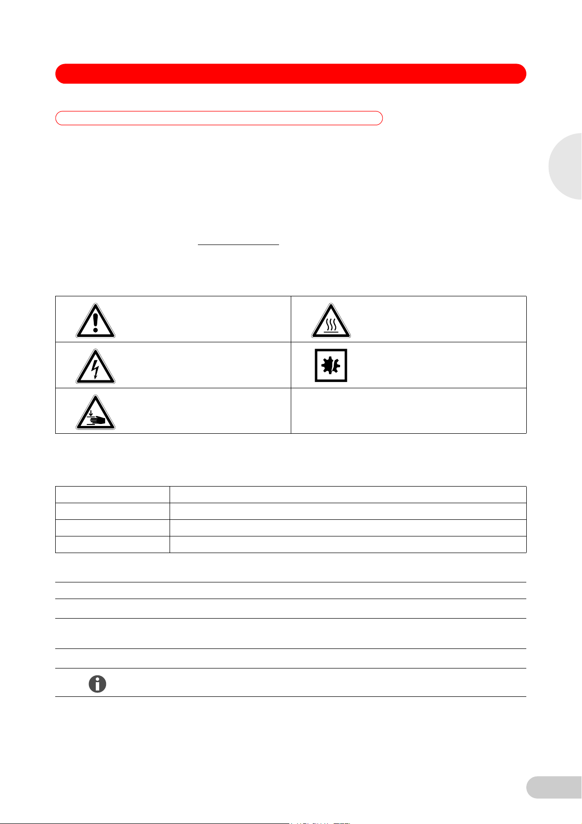
1.2 Danger symbols and danger levels
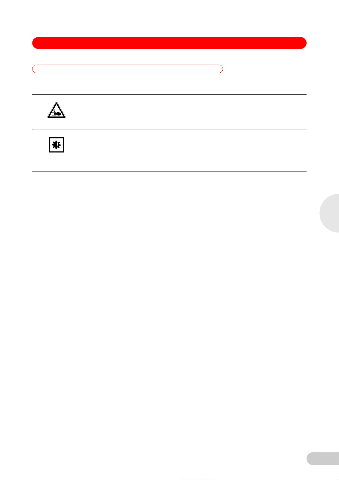
1.2.1 Hazard symbols
Hazard point Burns
Electric shock Material damage
.
1
Operating instructions
Crush
1.2.2 Degrees of danger
The following degree levels are used in safety messages throughout this manual. Acquaint
yourself with each item and the potential risk if you disregard the safety message.
DANGER Will lead to severe injuries or death.
WARNIN G May lead to severe injuries or death.
CAUTION May lead to light to moderate injuries.
NOTICE May lead to material damage.
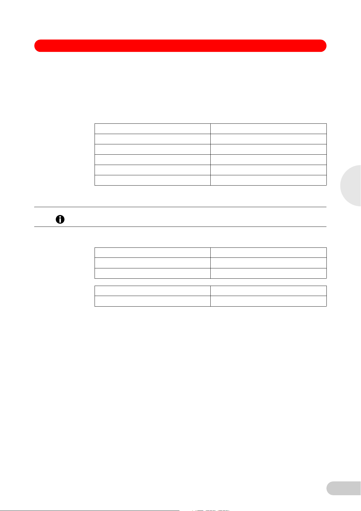
1.3 Symbols used
Example Meaning
You are requested to perform an action.
1.
2.
Perform these actions in the sequence described.
• List.
References useful information.
5
Page 6

1
Operating instructions
HEF® and G -86 °C Freezers — Operating manual
1.4 Abbreviations used
A Amp
CFC Chlorofluorocarbons
°C Degree Celsius
G Green
HEF High Efficiency
HCFC Hydrochlorofluorocarbon
Hz Hertz
kg Kilogram
lb Pound
m Meter
min Minute
mm Millimeter
N/A Not applicable
rpm Revolutions per Minute (min
ULT Ultra-Low Temperature
V Volt
-1
)
6
Page 7
HEF® and G -86 °C Freezers — Operating manual
2 Safety
2Safety
2.1 Intended use
New Brunswick HEF and G (Green) freezers are designed to provide precise, ultra-low
temperature environments for cold storage of scientific or medical materials. They are designed
to provide ultra-low temperature sample storage from -50 °C to -86 °C at 32 °C maximum
ambient operating temperature.
2.2 Warnings for intended use
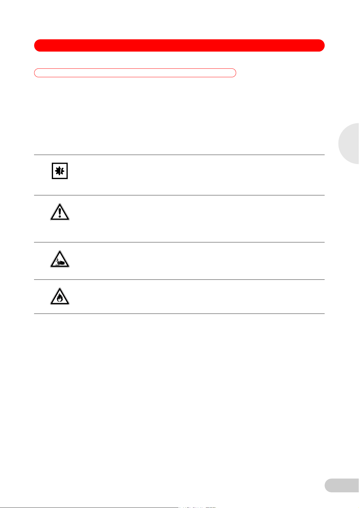
2.2.1 Manual conventions used
Risk of material damage
This equipment must be operated as described in this manual.
NOTICE!
Please read the entire operating manual before attempting to use this equipment. If
operational guidelines are not followed, equipment damage may occur.
Risk of personal injury
Do not use this equiment in a hazardous atmosphere or with hazardous materials for which
CAUTION!
the equipment was not designed.
Please read the entire operating manual before attempting to use this equipment. If
operational guidelines are not followed, personal injury may occur.
Risk of personal injury
Crush Warning messages alert you to specific procedures or practices regarding heavy
CAUTION!
objects which, if not followed correctly, could result in serious personal injury.
Risk of personal injury
Flammable warning messages alert you to possible risks of of personal injury and equipment
WARNING!
damage: protect the system from sparks and flames.
2
Safety
2.2.2 Health and safety at work act 1974
(FOR THE UNITED KINGDOM)
New Brunswick Scientific, as manufacturers and suppliers of laboratory equipment, are obliged
under the terms of the above Act to provide our users with instructions on the safe installation,
operation and maintenance of our equipment.
Our equipment is designed to acceptable standards and does not entail any hazard if used, as
advised in the attached instructions.
The following safety precautions should be observed by all personnel using this equipment:
1. Read and understand this manual. If in doubt, contact your local New Brunswick sales office.
2. Do not remove any covers. There are no operable controls other than those referred to in this
manual. There are voltages in excess of 41.5 volts AC behind the covers.
3. Use freezer gloves at all times when loading or unloading the equipment. The temperature of
operation is such that direct contact with the cold contents or inside the equipment can burn
unprotected skin.
4. Observe good housekeeping practices, at all times keeping the equipment and the adjacent
areas clean, dry and uncluttered.
5. Should any malfunctions occur or be suspected, immediately call a qualified service engineer
to investigate.
7
Page 8

2
HEF® and G -86 °C Freezers — Operating manual
6. The hydrocarbon (Group A3) refrigerants used in these freezers are flammable and therefore
appropriate attention must be paid to avoid leaks and to keep the freezer away from sparks
and flames.
Any person involved with working on or entering the refrigeration circuit should hold a current and
valid certificate from an industry-accredited assessment authority which authorizes his/her
competence to handle refrigerants (including hydrocarbons) safely in accordance with local
regulations and legislation.
Safety
8
Page 9
HEF® and G -86 °C Freezers — Operating manual
3 Product description
3 Product description
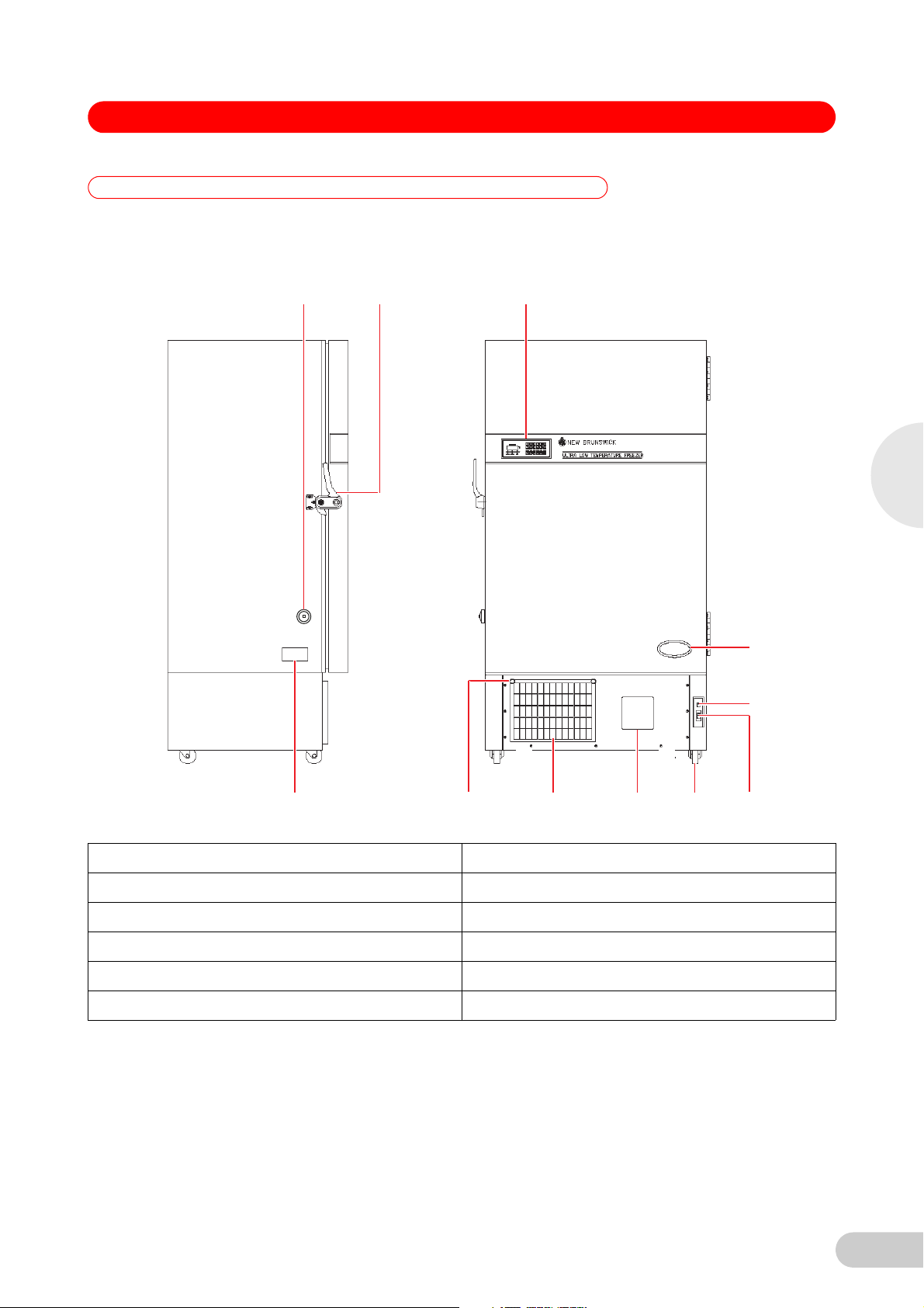
3.1 Main illustration
Abb. 1: Upright freezer - Side an d front views
12 3
3
Product description
4
5
76891011
Fig. 1: Upright freezer - Side and front views
1 Heated vent port 2 Door handle (lockable)
3 Control panel/display 4 Model label
5 Battery switch behind lockable panel 6 On/Off circuit breaker behind lockable panel
7 Transport castors 8 Chart recorder (optional)
9 Air filter grille 10 Quarter turn fastener
11 Specification plate
9
Page 10
HEF® and G -86 °C Freezers — Operating manual
3
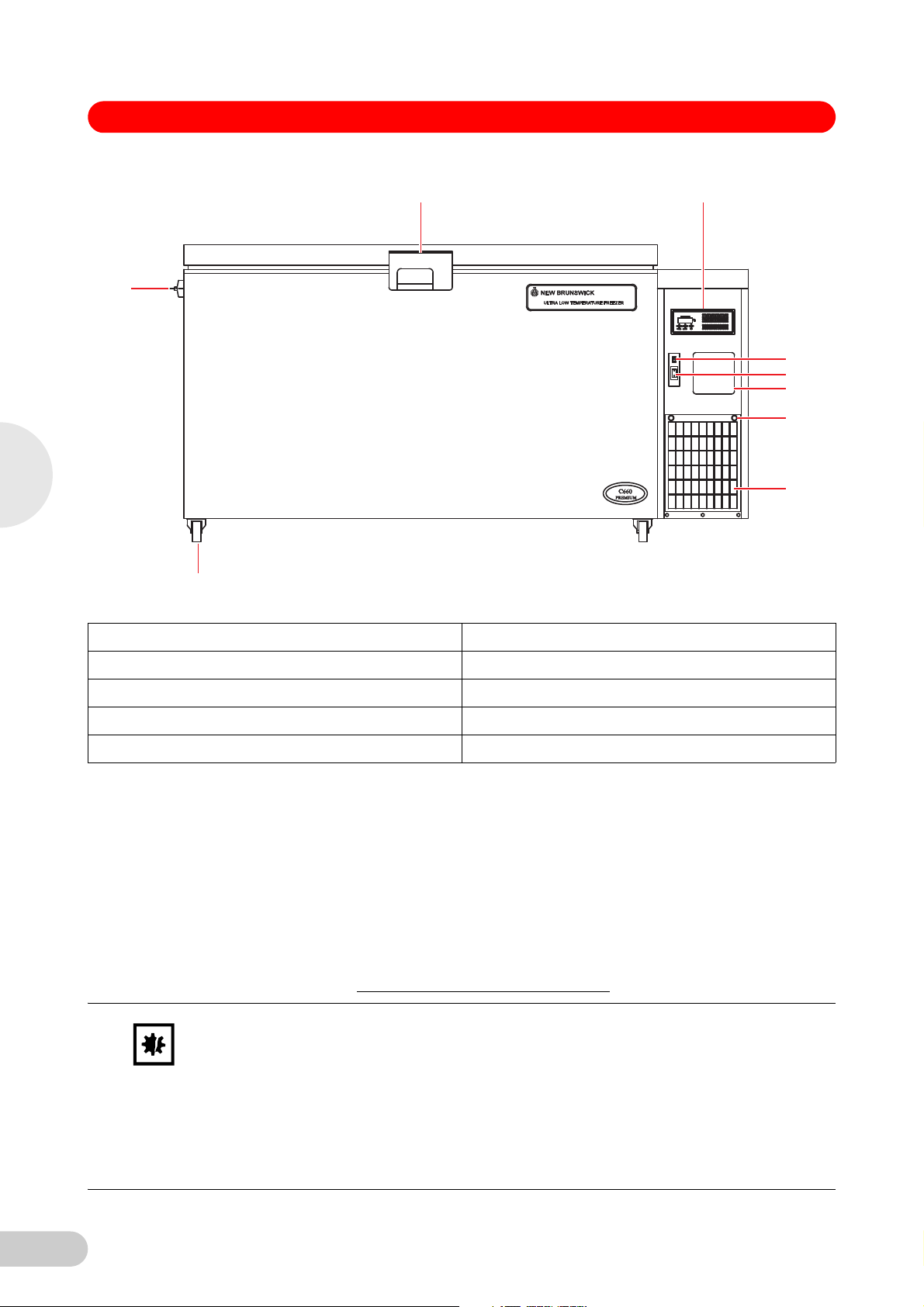
Abb. 2: Chest freezer - Front view
23
1
4
5
6
7
8
9
Fig. 2: Chest freezer - Front view
1 Heated vent port (inside compressor housing) 2 Lockable handle
3 Control panel/display 4 Battery switch (alarm) behind lockable panel
5 On/Off circuit breaker behind lockable panel 6 Chart recorder (optional)
Product description
7 Quarter turn fasteners 8 Air filter grille
9 Braked castors (front)
3.2 Delivery package
3.2.1 Inspection of boxes
Inspect the boxes carefully for any damage that may have occurred during shipping. Report any
damage to the carrier and to your local New Brunswick Sales Order Department immediately.
3.2.2 Packing list verification
Unpack your order, saving the packing materials for possible future use. Save the operating
manual for instruction and reference. Verify against your New Brunswick packing list that you
have received the correct materials, and that nothing is missing. If any part of your order was
damaged during shipping, is missing, or fails to operate, fill out the "Customer Feedback" form,
.
NOTICE!
available online at www.nbsc.com/CustomerFeedback.aspx
Risk of material damage
Vacuum insulation panels are used in the construction of Innova U725G and U410 HEF,
U570 HEF, and C660 HEF model freezers. Inspect the cabinet panels for punctures or other
damage that compromises the integrity of the product.
These panels are mounted in the cavity against the steel outer wall of the freezer. Any drilling
or puncture to the outer wall could release the vacuum from the panel, resulting in impaired
freezer performance.
Any unauthorized punctures or other damage deliberately made to the cabinet walls will
invalidate the warranty.
10
Page 11
HEF® and G -86 °C Freezers — Operating manual
3.3 Product versions
3.3.1 Introduction
This manual provides the user with the necessary information for installation and operation of
New Brunswick’s energy saving HEF and G range of Ultra-Low Temperature freezers: Innova
U725G, and the HEF models. It also provides some preliminary user maintenance information.
This manual covers the following freezer models:
Model (230 V, 50 Hz) Capacity
Innova U725-G Air-cooled 725 liters (25.6 cubic feet)
Innova U725-G Water-cooled 725 liters (25.6 cubic feet)
U410 HEF 410 liters (14.5 cubic feet)
U570 HEF 570 liters (20.1 cubic feet)
C660 HEF 660 liters (23.3 cubic feet)
®
3
All the above mentioned HEF and G freezers are totally free of CFCs (Chlorofluorocarbons) and
HCFCs (Hydrochlorofluorocarbons). They use HCs (Hydrocarbons) as refrigerants.
The use of Hydrocarbons as refrigerant is prohibited in the United States.
Hint!
The following HEF freezer models utilize HFCs (Hydrofluorocarbons) as refrigerants, and are
offered for the United States market.
Model (120 V, 60 Hz) Capacity
U410 HEF 410 liters (14.5 cubic feet)
U570 HEF 570 liters (20.1 cubic feet)
Product description
3.4 Features
Model (208 - 230 V, 60 Hz) Capacity
C660 HEF 660 liters (23.3 cubic feet)
The freezers are manufactured using high quality steel and electronics for long life. The HEF and
G-Series freezers have many features designed to provide ease of use and maintanence,
security and reliability to your ultra-low temperature storage needs. They are built to stringent
regulatory requirements for safety and environmental friendliness and disposability, and they are
CE and UL certified.
Features include:
• Designed to be exceptionally energy efficient and eco-friendly.
• A setpoint keypad and digital temperature readout are provided on a control panel, located on
the door of the upright freezers and on the console on the right side of chest freezers.
Controls for setting the freezer temperature and alarm warning setpoints are enabled by an
electronic lock. A unique code, which is selected by the user through the keypad, sets this
lock. The code can be changed at any time, provided the current setting of the lock is known.
On delivery, the lock code is "0000" (unlocked).
• Indicator lamps on the control panel provide warnings of power loss, system failure,
exceeding High/Low temperature setpoints, low battery voltage, and filter blockage. There is
also an LED to indicate when the freezer is under remote control via the RS-485 optional
computer interface.
• Heavy-duty commercially available compressors provide rapid temperature pull-down and
recovery after door opening.
11
Page 12

3
HEF® and G -86 °C Freezers — Operating manual
• A heated port with ice-clearing plunger prevents vacuum formation enabling the outer door to
be easily opened at anytime.
• All interior panels and shelves are made of high grade corrosion-resistant stainless steel,
making them durable and easy to keep clean and sterilize.
• Heavy duty castors enable easy installation and relocation.
• Two access ports allow easy addition of sensors, or of back-up systems that can provide
cooling protection for your samples in the case of a power outage or other system failure.
• An alarm contact is provided for connection to an external monitoring device or system.
• The freezers can be fitted with an optional 7-day circular chart recorder to provide
independent temperature recording.
• An automatic reset restarts freezers at random 15 second intervals to protect the
microprocessor controller from damage by electrical spikes caused by multiple freezers
turning on at once.
• Lockable freezer handles on outer door provide added security against unauthorized users.
• Multiple accessories are offered, including CO
systems, external voltage stabilizer, inventory racking, and more.
3.5 Warranty
New Brunswick Scientific equipment is protected by a comprehensive warranty. The warranty
covers faulty components and assembly, and our obligation under this warranty is limited to
repairing or replacing the instrument or part thereof, which shall prove to be defective after our
examination.
The warranty does not cover loss of time or materials, such as the loss of biological or
biochemical by-products caused by any work interruption resulting from equipment failure; it does
not extend to equipment that has been subject to misuse, neglect, accident or improper
installation or application; nor does it cover any machine that has been repaired or altered by
anyone other than an authorized factory-trained service representative, without prior written
Product description
approval from your local New Brunswick sales office or distributor.
Expendable items such as bearings and seals, lamps, probes, sensors, glass, filters, single-use
vessels, etc., are not covered.
The warranty begins on the date the equipment ships from New Brunswick Scientific or an
authorized distributor and extends through the period indicated in the chart below:
/LN2 back-up systems, remote monitoring
2
3.5.1 Warranty registration
3.5.2 Extended warranty option
12
Instrument Parts Warranty Labor Warranty
Freezers ULT Freezers 5 years; vacuum
insulation panels: 12
years
1
Accessories
1
Chart recorders, CO2/LN2 back-up systems, etc.
To register your warranty, complete the online form at www.nbsc.com
Help? tab.
A variety of service plans are offered to help minimize downtime from unexpected malfunctions in
equipment operation. Speak to your New Brunswick sales representative for more information.
1 year 1 year
2 years
under the How Can We
Page 13
HEF® and G -86 °C Freezers — Operating manual
4 Installation
4 Installation
4.1 Preparing installation
Risk of personal injury
DO NOT attempt to lift any freezer by hand. Preferred lifting for loading and unloading is by
WARNING!
NOTICE!
4.2 Selecting the location
mechanical lifting equipment.
Risk of material damage
Maintenance, adjustment and repair work should be carried out only by QUALIFIED,
EXPERIENCED personnel who have been AUTHORIZED to undertake such work by New
Brunswick Scientific or its authorized agents.
Failure to use authorized service agents will invalidate the warranty.
All freezers are mounted on castors for ease of movement. U725-G model freezers have feet that
provide both a leveling feature and a locking feature to stop the freezer from rolling once it is in
place. HEF upright freezers and chest freezers have locking front castors; locking front castors
do not provide leveling adjustment, so the site chosen for the freezer must have a flat, level floor.
Position the freezer to allow disconnection to be made in respect to removal of the plug or
appliance coupler, also the free air entry through the intake grille in the front and free air exit from
the back. Provide a clearance of at least 150 mm (6 in) on all sides.
For efficient temperature control, the freezer should be placed in a shaded area, away from
sources of excessive heat. For maximum cooling capability, the product should be located in an
air-conditioned room.
4
Installation
4.2.1 Occupancy rating (230 V, 50 Hz models only)
This equipment has a category A1 - B1 occupancy rating, with a refrigerant charge of less than
0.15 kg per sealed system.
Systems charged with less than 0.15 kg may be installed in any size room as long as adequate
ventilation is provided, in order to remove rejected heat from the freezer and to vent any sudden
loss of refrigerant in case of system failure.
4.2.2 Below ground installations (230 V, 50 Hz models only)
We recommend allowing at least 18 m
refrigerant concentration from exceeding 20 % of the Lower Flammability Limit (LFL) in the event
of a sudden loss of refrigerant into the room.
Basements and cellars must have adequate ventilation for the removal of heat rejected from the
freezer(s).
3
(23.5 yd3) room volume for each freezer, to keep the air/
13
Page 14

HEF® and G -86 °C Freezers — Operating manual
4.2.3 Installation categories (230 V, 50 Hz models only)
Category Examples Requirements
4
A1 (domestic/ public) Hospitals
B1 (commercial/ private) Business or professional
4.3 Requirements for water-cooled models
If your freezer has a water-cooled condenser, the following are water supply and drainage
requirements:
Minimum flow
requirements
Max Inlet pressure 10 bars
Min Inlet pressure 1 bar
Prisons
Theatres
Schools
Supermarkets
Hotels
Dwellings
offices
Shops
Restaurants
Laboratories
General manufacturing
3.8 liters/minute
< 0.15 kg refrigerant per
sealed system
< 0.15 kg refrigerant per
sealed system
Installation
Maximum supply
temperature
Minimum supply
temperature
Connection size Inlet : 15 mm x ½” BSPT
Water quality Water must be clean and free from particles that could cause
Drainage requirements
Typical Flow Rates At a setpoint of -85 °C, an ambient temperature of 25 °C, and a
1
Water consumption will increase as water temperature increases.
2
The condenser must never be allowed to freeze during operation. If, during normal cycling,
water temperature approaches 6.0 °C, this must be checked.
3
This installation requires checking the high stage discharge pressure and may require an
adjustment of the water regulating valve; both operations MUST be carried out by a qualified
engineer.
1
2
25 °C
7.0 °C
Outlet: 15 mm x ½” BSPT
blockage in the regulating valve or heat exchanger. A suitable
inline strainer must be placed in the inlet pipe if there is any doubt
about the cleanliness of the supply. (Minimum filter requirement is
60 mesh 0.25 mm aperture).
3
A recirculated cooler return line and a main supply line to the
waste drain are required.
water inlet temperature of 20 °C:
47 L/hr for the U725-G.
14
Page 15

HEF® and G -86 °C Freezers — Operating manual
4.4 Installing the shelves
Model U410 HEF and U570 HEF freezers are fitted with four adjustable shelves. Model U725
freezers are fitted with two adjustable shelves. These can be positioned in 12.7 mm (½ in) steps
anywhere throughout the freezer.
To effectively utilize racks within the freezer, be sure to position them so that each shelf is aligned
with the bottom of each inner door.
Perform the following steps to install the shelves:
1. Ensure that the freezer is turned off and unplugged.
2. Remove the protective plastic coating from the shelf.
3. Position the four shelf clips evenly within the freezer by squeezing the clip, then inserting it
into the shelf support within the freezer.
4. Place the shelf in the freezer, making sure all four shelf clips are supporting the weight of the
shelf.
To readjust the shelf or shelf clips, gently squeeze the shelf clip to release it from the side of the
freezer, then reposition it as needed.
4.5 Lockable freezer handle
Freezers are supplied with lockable handles.
The C660 HEF handle is fitted with a quarter turn key lock.
The upright freezer handle is fitted with barrel locks (push in and turn key to lock, turn key to
unlock; the barrel will only lock when a key is turned to the lock position). The barrel lock may be
removed from the upright freezer handle if the lock feature is not required.
An optional padlock adaptor can provide extra security by allowing the addition of a
customer-supplied padlock to secure the freezer handle.
Removing the upright freezer handle barrel lock
Perform the following steps to remove the barrel lock from the upright freezer handle, if the lock
feature is not required:
4
Installation
1. Open the freezer door and place the freezer handle in closed position.
15
Page 16

HEF® and G -86 °C Freezers — Operating manual
2. Remove the two screws from behind the lock barrel.
1
2
3
4
4
Installation
1 Freezer handle 2 Screw (1 of 2)
3 Lining plate 4 Freezer door wall
3. Remove the lining plate and lock barrel.
4. Insert the plastic blanking plug supplied.
5. Insert the lining plate and screw in the two screws.
It is important that the handle lock lining plate be installed at all times.
Hint!
Risk of material damage
DO NOT SLAM THE DOOR WITH THE HANDLE IN THE CLOSED POSITION.
NOTICE!
6. Place freezer handle in open position and close freezer door.
The door handle has a cam action to pull the door closed and a reverse cam action to break the
seal so the door can be opened. When closing the outer door, ensure that the cam is engaged for
correct operation. The initial vacuum inside the cabinet may cause the door to appear closed, but
when the vacuum releases, the door will open. Always ensure the handle is properly engaged. It
is important that the heated vent port is kept clear. This will avoid putting undue stress on the
handle mechanism.
16
Page 17

HEF® and G -86 °C Freezers — Operating manual
5 Operating controls and function
5 Operating controls and function
5
5.1 Controls and function
Operating controls are located on a control panel mounted in the door of the upright freezers, and
on the console on the right side of chest freezers.
Every New Brunswick freezer is equipped with S.M.A.R.T. Plus™ diagnostic software, to help
identify the cause of a fault or setpoint variance.
This section describes the controls and function of the control panel, (see Fig. 3 on p. 17).
Abb. 3: Display panel & keypad
TEMPERATURE
1
12
8
Fig. 3: Display panel & keypad
REMOTE-CONTROL
TEMP-ALARM
FILTER-CLEAN BATTERY-LOW
POWER-FAIL FAULT
C
1315
1
23456
78 90EC
ALARM
SET
TEMP
LOW
ALARM
HIGH
ALARM
LOCK
CODE
CHANGE
TEST/
MUTE
10927543 6
Operating controls and function
14
11
Temperature °C Display
Item Name Function
1 TEMPERATURE °CThe digital display normally shows the current internal
temperature of the freezer. Temperature is displayed in 1°C
increments.
High alarm/low alarm
Item Name Function
2 & 8 [HIGH/LOW]
TEMP-ALARM
The TEMP-ALARM illuminates and the audible alarm sounds if
the freezer’s internal temperature is above/below the
user-selected alarm setpoints. The LED illuminates as soon as
the setpoint is passed. The high temperature audible alarm has
a programmable delay (see Setting the alarm delay on p. 25).
After the temperature returns to the normal range, the
TEMP-ALARM switches off and the audible warning stops.
The audible alarm can be silenced by pressing the ALARM TEST/MUTE KEY. If the temperature
Hint!
has not returned to normal range after the programmed time period, the audible warning will
sound again. This pattern will continue to repeat until the temperature returns to normal.
17
Page 18

HEF® and G -86 °C Freezers — Operating manual
5
Operating controls and function
Temp-alarm light
Item Name Function
8 TEMP-ALARM Should a mains/power failure cause the temperature to surpass
the alarm setpoint, the TEMP-ALARM illuminates. (The audible
alarm will already be sounding due to the mains/power failure).
The TEMP-ALARM lamp will extinguish when the temperature
returns to normal set range. Cancel the TEMP-ALARM by
pressing the ALARM TEST/MUTE KEY.
Power fail light
Item Name Function
3 POWER-FAIL Illuminates if the mains/power supply fails, flashing at
approximately 10-second intervals, accompanied by an audible
alarm. When mains/power is restored, the indicator goes off
and the audible alarm stops. (The battery must be switched on
and charged for this indicator to operate.)
Fault light
Item Name Function
4 FAU LT Illuminates if there is a system failure within the freezer.
Interfacing with the S.M.A.R.T. Plus™ diagnostics via the
control panel, the fault can be determined (see Error messages
on p. 34). System failure is accompanied by an audible alarm.
Correction of the fault extinguishes the light and audible alarm.
Battery low light
Item Name Function
5 BATTERY-LOW With mains/power ON: illuminates if battery voltage is below 6
volts, flashes when voltage drops to 5 Volts. With mains/power
OFF: if battery voltage drop below 5.5 Volts, this fault indicator
will stop functioning.
Filter clean light
Item Name Function
6 FILTER-CLEAN Illuminates, accompanied by an audible alarm, to indicate a
blocked or dirty filter. Filter is located on the front at the bottom
of all freezers. Remove by turning the two thumbscrews on the
filter holder ¼ turn. Clean filter by washing in mildly soapy
water, then air dry. If filter warning light does not go out after
replacing the cleaned filter, contact your local New Brunswick
service representative.
18
Remote control light
Item Name Function
12 REMOTE
CONTROL
Indicates when freezer is operating under remote computer
control via the optional RS-485 interface port and New
Brunswick's BioCommand
data logging software.
®
SFI software, or other laboratory
Page 19

HEF® and G -86 °C Freezers — Operating manual
The keypad controls are locked when the freezer is under remote control.
Hint!
Set temp key
Operation in normal mode with LOCK lamp off.
Item Name Function
7 SET TEMP Displays current temperature setting. Used to change
temperature settings.
High alarm/low alarm keys
Operation in normal mode with LOCK lamp off.
Item Name Function
2 HIGH-ALARM Displays current high alarm temperature setting.
2 LOW-ALARM Displays current low alarm temperature setting.
Lock key
Operation in normal mode with LOCK lamp off.
5
Operating controls and function
Item Name Function
9 LOCK Locks and unlocks the control panel for programming
sequence.
Code change key
Operation in normal mode with LOCK lamp off.
Item Name Function
10 CODE CHANGE Used to change freezer lock codes. Inactive in normal mode.
Alarm test/mute key
Operation in normal mode with LOCK lamp off.
Item Name Function
11 ALARM TEST/
MUTE
Using the TEST/MUTE button does NOT cancel remote alarm monitor socket switching.
Hint!
Sounds the audible alarm. If the audible alarm is on due to a
fault condition, press this key to silence the alarm. The lamp
LED lights can also be tested by pressing this key. The lights
should all illuminate and the display should read “8888”.
"E" key
Operation in normal mode with LOCK lamp off.
Item Name Function
13 E Used to enter data when programming.
19
Page 20

HEF® and G -86 °C Freezers — Operating manual
5
Operating controls and function
"C" key
Operation in normal mode with LOCK lamp off.
Item Name Function
14 C Used to cancel data when programming.
Numerical keys
Operation in normal mode with LOCK lamp off.
Item Name Function
15 NUMERICAL
KEYS (1-0)
Used to input data when programming. Keys 8 and 9 are also
used to program alarm delays (see Setting the alarm delay on
p. 25).
20
Page 21

HEF® and G -86 °C Freezers — Operating manual
6 Operation
6 Operation
6.1 Getting started
Risk of personal injury
BEFORE connecting the freezer to the mains/electrical supply, make sure that the mains/
WARNING!
6.1.1 Plug in
power supply matches the requirements of the equipment. Check the specification plate
(located on the side of the freezer) for the electrical requirements. The equipment should be
connected to an earthed/grounded outlet socket.
Once you have verified that the mains/power supply matches the electrical requirements of the
freezer, connect the product to the mains/power supply using the mains/power cord provided.
Risk of personal injury
If the freezer’s voltage rating does not match your mains/electrical supply, or if the plug on the
WARNING!
mains/power cord does not fit the outlet, do not plug the freezer in.
Contact your laboratory supervisor, safety officer, or qualified service or electrical engineer.
Risk of material damage
Some freezers are supplied with more than one removable mains/power cord. Utilize the cord
NOTICE!
6.1.2 Turning the freezer On/Off
that matches your power receptacle. Check the voltage rating plate on the side of the freezer,
to confirm that the freezer is compatible with your laboratory mains/power supply.
6
Operation
WARNING!
Hint!
Risk of personal injury
The On/Off circuit breaker and battery switch are fitted with IP65 plastic covers, to prevent a
possible source of ignition. These covers must not be removed. If one of the covers needs to
be replaced, the replacement must be performed by a qualified and authorized person.
Failure to observe this safety warning will invalidate the warranty and could result in a
dangerous situation in the event of a failure.
The ON/OFF circuit breaker is located within the lockable panel at the bottom right-hand corner
of the upright freezer or to the left of the control panel on the chest model.
To remove the lockable panel and turn the circuit breaker and battery switch On/Off:
1. Insert and turn the key (provided) one quarter turn to the right.
The key can be removed to prevent access.
2. Remove the panel.
3. Set the ON/OFF circuit breaker and battery switch to the I (ON) position.
The temperature display illuminates immediately.
21
Page 22

1
2
6
Operation
HEF® and G -86 °C Freezers — Operating manual
Abb. 4: Upright freezers switch location
Fig. 4: Upright freezers switch location
1 Battery switch 2 On/Off circuit breaker switch
Abb. 5: Chest freezers switch location
1
2
Fig. 5: Chest freezers switch location
1 Battery switch 2 On/Off circuit breaker switch
The compressors will not operate for approximately three minutes after connection of the mains/
Hint!
power supply, because there is an automatic delay device in the circuit. Temperature and alarm
settings can be adjusted immediately.
6.1.3 Alarm/battery activation
The equipment is delivered with the battery deactivated. The Power Fail alarm is activated by the
battery rocker switch within the lockable panel, which is located at the bottom right-hand corner.
The switch is labelled I (ON) and O (OFF) (see Fig. 4 on p. 22) and (Fig. 5 on p. 22).
To activate the alarm, place the battery switch in the I position.
Failure to turn on the battery switch may lead to a discharged battery, low battery alarm
Hint!
indication, and/or a disabled alarm system.
After activating the alarm, test its operation by pressing the ALARM TEST/MUTE key on the
display.
The audible alarm should sound.
The ALARM TEST/MUTE key also tests the LED lamps. All of the LEDs should light up together
when the button is pressed.
22
Pull down time to -86 °C will be dependent on the freezer size and model (see Specifications on
Hint!
p. 36). The alarm will sound every 30 minutes until the temperature setpoint is reached. Use the
ALARM TEST/MUTE key to mute the alarm during this initial pull-down period.
Page 23

HEF® and G -86 °C Freezers — Operating manual
If the freezer is turned off during the initial pull-down period, the alarm will activate 30 minutes
after switching it back on.
The factory-set temperature is -80°C.
6.1.4 Testing the alarm monitoring socket
The freezer is fitted with a remote alarm socket for testing power-fail and low battery alarms, and
for connection to an external building monitoring system or optional auto-dialer, (see Alarm
monitoring socket on p. 26). To test the alarm monitoring socket.
Tur n o f f (O) the ON/OFF circuit breaker.
This will test the POWER FAIL and ALARM output at the same time.
The battery must be switched on to test the POWER FAIL. The remote alarm facility provides
voltage-free contacts rated at 1 amp, 24 volts maximum.
6.1.5 Vacuum effect
After closing the freezer door, a vacuum may be created. Before the door can be opened again, it
may be necessary to wait two or three minutes for the vacuum to be released by the vent port. Do
not try to force the door. During the release of the vacuum, a slight hissing may be heard. In
order to minimize vacuum formation, the vent heater assembly has a spring-loaded plunger to
clear ice from the inside of the vent.
Be careful not to place a rack directly against the vent, as this will inhibit the plunger’s ability to
Hint!
operate correctly (see Heated vent port on p. 29).
6
Operation
6.2 Programming the freezer
Set the freezer to any temperature within the range from -50 °C to -86 °C.
All temperature setpoints are automatically negative °C.
Hint!
6.2.1 Setting operating temperature
To set the operating temperature for the freezer:
1. Press the LOCK key.
The LOCK lamp will flash if a lock code (password protection) is required, (see Changing lock
Hint!
codes on p. 25).
The LOCK lamp will illuminate, indicating the system is unlocked and parameters can be
changed.
2. Press the SET TEMP key.
Its indicator will flash and the display will indicate 0.
3. Using the numerical keys, enter a new temperature (from -50 °C to -86 °C).
The temperature selected will appear in the TEMPERATURE display.
4. When the correct temperature is displayed, press the E key to enter the data. To set the high
alarm setpoint skip to (see Setting high alarm setpoint on p. 24), step 2.
The SET TEMP lamp will go off.
5. Press the LOCK key to exit programming.
The LOCK lamp will go off and the freezer will return to normal mode.
Press the C key to clear the display during programming.
Hint!
23
Page 24

6
Operation
HEF® and G -86 °C Freezers — Operating manual
6.2.2 Setting high alarm setpoint
The high alarm setpoint may not be warmer than -10 °C and may not be less than within +5° of
the operating temperature. The default setting is +5° from the temperature setpoint.
1. Press the LOCK key.
The LOCK lamp will flash if a lock code (password protection) is required, (see Changing lock
Hint!
codes on p. 25).
The LOCK lamp will illuminate, indicating the system is unlocked and parameters can be
changed.
2. Press the HIGH ALARM key.
Its indicator will flash and the display will indicate 0.
3. Using the numerical keys, enter a new alarm setpoint temperature.
The selected temperature will appear in the TEMPERATURE display.
4. When the correct temperature is displayed, press the E (Enter) key to enter the data. To set
the low alarm setpoint skip to (see Setting low alarm setpoint on p. 24), step 2.
The HIGH ALARM indicator will turn off.
5. Press the LOCK key to exit programming.
The LOCK lamp will go off and the freezer will return to normal mode.
Press the C key to clear the display during programming.
Hint!
6.2.3 Setting low alarm setpoint
The low alarm setpoint may not be colder than -91 °C and may not be more than within -5° of the
operating temperature. The default setting is -5 °C from the temperature setpoint.
1. Press the LOCK key.
The LOCK lamp will flash if a lock code (password protection) is required, (see Changing lock
Hint!
codes on p. 25).
The LOCK lamp will illuminate, indicating the system is unlocked and parameters can be
changed.
2. Press the LOW ALARM key.
Its indicator will flash and the display will indicate 0.
3. Using the numerical keys, enter a new alarm setpoint temperature.
The selected temperature will appear in the TEMPERATURE display.
4. When the correct temperature is displayed, press the E (Enter) key to enter the data.
The LOW ALARM indicator will turn off.
5. Press the LOCK key to exit programming.
The LOCK lamp will go off and the freezer will return to normal mode.
24
Press the C key to clear the display during programming.
Hint!
Page 25

HEF® and G -86 °C Freezers — Operating manual
6.2.4 Checking temperature and alarm setpoint settings
To view the currently set operating temperature, high alarm setpoint, or low alarm setpoint for the
freezer.
Press the SET TEMP key, HIGH ALARM key, or the LOW ALARM key and read the display.
If you press the SET TEMP, HIGH ALARM or LOW ALARM key while the LOCK key lamp is
Hint!
flashing, the display will read ---- , which indicates that the freezer is locked.
6
6.2.5 Setting the alarm delay
The HIGH ALARM audible alarm and the REMOTE ALARM monitoring socket can be
programmed to a time delay set between 0 and 40 minutes.
The default time delay is 30 minutes. If the time delay is set to 0 minutes, the system will program
it as 15 seconds.
Press KEY 8 to display the High Temperature audible alarm delay, and press KEY 9 to display
Hint!
the Remote Alarm Socket switching delay.
To set the audible HIGH ALARM delay (KEY 8):
1. Press the LOCK key.
The LOCK lamp illuminates, indicating the system is unlocked and parameters can be
changed.
2. Press keypad button 8.
pp flashes on the display.
3. Enter the desired value (e.g., press keypad buttons 1 and 0 to designate 10 minutes).
4. Press the E (Enter) key.
The LOCK lamp goes out.
To set the REMOTE ALARM socket time delay (KEY 9):
1. Press the LOCK key.
The LOCK lamp illuminate, indicating the system is unlocked and parameters can be
changed.
2. Press keypad button 9.
pp flashes on the display.
3. Enter the desired value (e.g., press keypad button 5 to designate 5 minutes).
4. Press the E (Enter) key.
The LOCK lamp goes out.
If the number entered is valid, --- flashes on the display, the value has been stored, and the
LOCK lamp goes out. (This is a one-shot operation.)
If the number entered is out of range, –EE– shows on the display and the operation will need to
be repeated using a valid number.
Operation
6.2.6 Changing lock codes
If you enter a lock code when there is none, or if you replace an existing lock code with a new
Hint!
one, take note of the new code before you enter it.
If the code is forgotten, you will need to contact Customer Service to regain access to the
programming mode of the freezer.
25
Page 26

6
Operation
HEF® and G -86 °C Freezers — Operating manual
The freezer is delivered unlocked. To change the code, the freezer must be unlocked. If a lock
code has already been set (indicated by the LOCK lamp flashing when the LOCK key is
pressed), that same code must be entered to unlock the freezer. When the freezer is unlocked,
the LOCK lamp is on (not flashing).
Once the freezer is unlocked, follow these steps to set a new lock code:
1. Press the CODE CHANGE key.
The lamp will flash and the display will go blank.
2. Using the numerical keys, enter the new four-digit number. Check it on the display.
3. Press the C key to cancel the entry if the display shows it to be incorrect, then enter the
correct number.
4. When the number is correct, record the new number somewhere secure. Then press the E
(Enter) key.
The CODE CHANGE indicator will turn off.
5. Press the LOCK key.
Its indicator lamp will turn off.
The freezer now has a new lock code. If at any time you wish to change this code, you will have
to enter this code to unlock the system before you can enter a new code.
Setting the lock code to 0000 disables the lock completely. With the 0000 code, you would need
only press the LOCK key to reprogram the freezer.
6.2.7 Setting the temperature offset
The temperature offset function enables to add a temperature offset to the factory defined
temperature settings.
1. Press the LOCK Key.
2. Press the C key to access the offset function.
3. Press 0, 1, 2, 3, or 4 key to set the offset in degrees.
4. Press the ENTER key to confirm selection.
Set temperature offset to "0" for no offset.
Hint!
6.3 Battery backup switch
This is a rocker switch labeled I/O behind the locked front panel. In the O position, the battery is
disconnected. This position should only be used while in transit, in storage, or to change the
battery.
At all other times the switch should be kept in the I position for the battery to be charged, and for
the alarm function to be available in the event of mains/power failure. (Failure to set the switch
may result in impaired battery life, and the alarm will not trigger if the mains/power fails.)
With the battery switch on, during a mains/power failure, the internal freezer temperature will be
displayed at ten-second intervals, and the audio alarm will also sound. The audible alarm may be
muted by pressing the ALARM TEST/MUTE key on the control panel, but will sound again after
30 minutes if the fault has not been corrected. Pressing the same button again will mute the
alarm for an additional 30 minutes; the pattern will continue to repeat until the initial problem is
corrected.
6.4 Alarm monitoring socket
The freezers are provided with an alarm monitoring socket at the rear of the freezer and a
matching plug for external monitoring. This plug can be connected either to a central monitoring
system such as a building management system, or to a remote alarm via an auto-dialer.
26
Page 27

HEF® and G -86 °C Freezers — Operating manual
1
2
3
123
Abb. 6: Upright freezers alarm monitoring socket
Fig. 6: Upright freezers alarm monitoring socket
1 RS-485 connector (optional) 2 Alarm monitoring socket
3 Mains/power socket
Abb. 7: Chest freezers alarm mo nitoring socket
6
Operation
Fig. 7: Chest freezers alarm monitoring socket
1 RS-485 connector (optional) 2 Alarm monitoring socket
3 Mains/power socket
NOTICE!
The configuration of the socket is shown in (Fig. 8 on p. 28) and (Fig. 9 on p. 28), as viewed from
the rear of the freezer. Within the freezer, the socket is connected to voltage-free contacts rated
at 24 volts, 1 amp. In normal operation, with the mains/power on, pin 1 is connected to pin 2 (N/
C), and in the alarm condition, with mains/power off, pin 1 is connected to pin 3.
The High Temperature Alarm output to the Remote Alarm Monitoring Socket can be programmed
to a set time delay (see Setting the alarm delay on p. 25).
Risk of material damage
Hazardous voltages must not be connected to the remote alarm socket. Max Rating 24 V 1 A.
27
Page 28

6
Operation
HEF® and G -86 °C Freezers — Operating manual
Abb. 8: Remote alarm socket - upright f reezer
Fig. 8: Remote alarm socket - upright freezer
Abb. 9: Remote alarm socket - chest free zer
Fig. 9: Remote alarm socket - chest freezer
28
Page 29

HEF® and G -86 °C Freezers — Operating manual
7 Maintenance
7 Maintenance
7.1 Cleaning
Risk of material damage
Maintenance, adjustment and repair work should be carried out only by QUALIFIED,
NOTICE!
7.1.1 Painted surfaces
7.1.2 Panels and shelves
7.1.3 Air intake grille and filter
EXPERIENCED personnel who have been AUTHORIZED to undertake such work by New
Brunswick Scientific or its authorized agents.
Failure to use authorized service agents will invalidate the warranty.
All exterior paint work and inner doors should be cleaned using a solution of mild detergent in
water. Do not use abrasive cleaners or solvents.
The interior panels and shelves are made of stainless steel. They may be cleaned and sterilized.
7
Maintenance
NOTICE!
7.1.4 Heated vent port
Hint!
Risk of material damage
Serious damage to the freezer may result if the air intake is blocked. Check that there is no
obstruction of the airflow to the freezer. The air intake filter must also be cleaned regularly.
Remove the filter from behind the grille by turning the thumbscrews ¼ turn and opening grille
downward. The filter should be washed in warm soapy water and left to air dry before
replacing.
The air intake grille must be cleaned regularly to keep it free from dust and debris. Under normal
conditions, clean the grille once every three months. If the area around the freezer is very dusty
or dirty, clean the grille more often.
Brush the grille with a soft brush and, if a vacuum cleaner is available, vacuum the dust from
the grille.
There is an electrically-heated vent port in the freezer which must not be allowed to become
blocked or sealed off.
Over a period of a few weeks, depending on how often the freezer is being used, a small
mushroom of ice will form around the end of the vent port. If the vent port is allowed to become
blocked, a vacuum will be created when the door is closed. It will not be possible to open the door
or lift the lid until the vacuum has leaked away through the seal, which can take up to two hours
due to the high quality of the seals.
The vent port is located on the left-hand side of the freezers.
If the door cannot be opened, clear the vent port by pressing the manual plunger on the
outside of the air vent.
29
Page 30

7
7.1.5 Door or lid seal
Maintenance
HEF® and G -86 °C Freezers — Operating manual
123
1Plunger 2Cover
3 Freezer outer wall
Be sure to treat the door or lid seal with care. Avoid damaging this seal in any way. The freezer
cannot operate properly with a defective seal.
It is advisable to wipe both the seal and the surface against which it seals with a soft dry cloth
once a month.
7.2 Routine maintenance
7.2.1 Lubrication
Every 12 months the outer door hinges and the handle mechanism should be lightly lubricated
using general-purpose oil or spray grease.
7.2.2 Defrosting
After an extended period of operation, defrosting may become necessary:
Risk of material damage
Do not attempt to chip or scrape the ice with a sharp instrument. Allow the ice to melt
NOTICE!
naturally.
1. De-activate the alarm by switching the battery (alarm) switch (located behind the lockable
panel on the front of the freezer) to off (O).
2. Unplug the freezer from the mains/electrical supply.
3. Leave the innner and outer doors or lids open.
4. Allow the accumulated ice to melt.
5. Mop up the resulting water.
6. Dry and decontaminate the interior of the freezer.
7. When defrosting is complete, reconnect the freezer to the mains/electrical supply.
8. Turn the mains/power switch on (I) and re-activate the battery (alarm) switch.
7.2.3 Removing the inner doors (upright freezers except U725-G)
The inner doors of the freezer can be removed for defrosting and cleaning. To remove the inner
doors of the upright freezers (except U725-G):
1. Fully open the outer door of the freezer.
2. Unscrew the door hinges.
30
Page 31

HEF® and G -86 °C Freezers — Operating manual
1
2
3. Remove the inner door and set aside.
Abb. 10: Screw hinge inner door
Fig. 10: Screw hinge inner door
1 Inner door 2 Door hinge screw x4
7
Maintenance
Repeat procedure for each door.
7.2.4 Replacing the inner door (upright freezers except U725-G)
To reinstall the inner doors of the upright freezers (except U725-G):
1. Fully open the outer door of the freezer.
2. Reposition inner door in closed position.
3. Screw on door hinges.
4. If required, adjust by loosening the screws.
5. Close outer door.
31
Page 32

7.2.5 Removing the inner doors (U725-G)
1
2
7
Maintenance
HEF® and G -86 °C Freezers — Operating manual
To remove the inner doors of the U725-G freezer:
1. Fully open the outer door of the Freezer.
2. Fully open the inner door.
3. Lift off inner door from hinges and set aside.
Abb. 11: Lift-off inner door
Fig. 11: Lift-off inner door
1 Inner door 2 Lift-off hinge
Repeat procedure for each door.
7.2.6 Replacing the inner door (U725-G)
To replace the inner door of the U725-G freezer:
1. Fully open the outer door of the freezer.
2. Fit door to hinge pins and close.
3. Check to ensure that inner door gasket is sealing against the freezer trim.
4. If required, adjust the latch retainer by loosening the screws and moving forward or
5. Close outer door.
backwards.
32
Page 33

HEF® and G -86 °C Freezers — Operating manual
7.2.7 Electrical components
Risk of personal injury
All electrical components that could cause possible ignition of refrigerant vapor during normal
WARNING!
operation have been enclosed in an IP65 enclosure.
During routine maintenance, care must be taken to avoid any damage to the gaskets and
sealing grommets of these enclosures; also check the gaskets and sealing grommets
routinely to ensure their integrity. Should any damage or deformity be detected, the gasket
and/or sealing grommet must be replaced immediately.
Failure to observe this safety warning will invalidate the warranty and could result in a
dangerous situation.
Lamps
Regularly check the indicator lamps:
Press the ALARM TEST/MUTE key.
All of the indicator lamps should illuminate, and the display should read 8888.
Alarms
Regularly check the alarm:
Press the ALARM TEST/MUTE key.
The TEMP indicator should illuminate and the audible alarm should sound.
7
Maintenance
NOTICE!
NOTICE!
Hint!
Battery replacement
Risk of material damage
There are no user controls behind any panels. The removal of any other part or panels from
the freezer by anyone other than a qualified, authorized Service Engineer may invalidate the
warranty.
Risk of material damage
Use only a replacement battery of the correct type and part number.
The battery must be fitted so the terminals correspond to the polarity labels on the electrical
panel.
The YUASA–NP6 V 2.8 Ah battery is mounted on the electrical panel. This is located behind the
right-hand base cover.
To replace the battery:
1. Switch off the mains/power switch and disconnect the mains/power supply.
2. Remove the side cover and the battery clamp securing the battery to the electrical panel.
3. Disconnect the battery terminals.
4. Install the new battery, fixing screws, and the side cover.
Be certain, when reconnecting the battery, to respect the correct polarity (red is + positive and
black is – negative).
5. Reconnect the freezer to the mains/power supply and turn the mains/power switch on (I).
Fuses
Fuses must be replaced by a New Brunswick Scientific approved service engineer. Contact New
Brunswick Service.
33
Page 34

HEF® and G -86 °C Freezers — Operating manual
8 Troubleshooting
8 Troubleshooting
8.1 General errors
If you are experiencing a problem with your freezer, check the following troubleshooting guides
before contacting your New Brunswick authorized Service technician.
8
8.2 Error messages
Troubleshooting
Symptom/
message
Door will not
open
Cause Remedy
1. The door handle is locked.
2. The heated vent port is
blocked.
1. Unlock the door handle.
2. Break up the ice in the vent port using
the plunger, (see Heated vent port on
p. 29).
If the door will not open:
Call New Brunswick Service.
FILTER-CLEAN
LED lights up
• Filter is contaminated. Clean the filter, (see Air intake grille
and filter on p. 29).
If the LED remains lit:
Call New Brunswick Service.
Your electronically-controlled New Brunswick freezer incorporates the unique Systems
Monitoring And Reporting Technology (S.M.A.R.T. Plus™) self-diagnostic software to diagnose
faults in its electronic systems, its probes and/or its refrigeration system.
This table interprets error codes that may appear in the control panel display:
Symptom/
message
E-01
E-02
E-03
E-04 Air-cooled condenser
Cause Remedy
• PT100 Probe 1 failure. This
probe, located inside the
freezer cabinet, indicates
cabinet temperature.
• Probe 2 failure. This probe
monitors the cascade
condenser.
• This probe monitors the
air-cooled condenser.
temperature too high:
1. Filter may be blocked.
2. Ambient temperature may be
too high.
If alarm continues to sound:
Call New Brunswick Service department.
Call New Brunswick Service department.
Call New Brunswick Service department.
1. Clean filter according to the instructions
(see Air intake grille and filter on p. 29).
2. Cool the room.
Call New Brunswick Service department.
• Fan may have failed.
• Water supply not turned on,
insufficient flow, regulating
valve not opening or
defective (water-cooled
version only).
34
A fan is required to cool the compressors on the water-cooled models.
Hint!
Page 35

HEF® and G -86 °C Freezers — Operating manual
8.3 After a mains/power failure
If mains/power is interrupted, the POWER-FAIL indicator lamp (see Fig. 3 on p. 17), Item 3, will
illuminate. In addition, the audible alarm will sound and the display will flash at approximately
10-second intervals.
When mains/power is restored, both alarm and light will automatically be cancelled.
If mains/power has been interrupted for only a short time, the internal temperature of the freezer
will not have risen above the temperature setpoint (the user-set alarm threshhold), so normal
operation will be resumed immediately.
If the interruption was long enough for the internal temperature to rise above the temperature
setpoint, the TEMP-ALARM indicator will illuminate. If the internal temperature does not fall
below the temperature setpoint within the programmed time after mains/power was restored, the
audible alarm will sound again. The TEMP-ALARM indicator will extinguish when the internal
temperature reaches the High Alarm temperature set point.
8.4 Interior warming
If the lid or door is left open long enough for the internal temperature to rise above the
temperature setpoint, the same effects will be observed as described above regarding power
failure.
To minimize the risk of this happening, the lid or door should only be opened when necessary, for
a short period of time.
The upright freezers are fitted with internal doors which latch shut, minimizing temperature rise
when the outer door is opened. Chest freezers are fitted with inner insulating lids to ensure
efficient running of the freezer. The lids should remain fitted at all times when the freezer is
running.
8
Troubleshooting
35
Page 36

HEF® and G -86 °C Freezers — Operating manual
9 Technical data
9 Technical data
9.0.1 Specifications
9.0.2 Specifications for U725-G Air-cooled and U725-G Water-cooled freezers
Part No. U9440-0005 U9440-0004
Internal Dimensions:
Height x Width x Depth
External Dimensions:
Height x Width x Depth
Capacity 725 Liters
Net Weight 315 kg
Lock Standard Standard
No. Compartments 33
9
Technical data
Interior Stainless steel grade 304L
Alarms High/Low temperature, power fail, battery low, filter clean, fault
Insulation Material Vacuum insulation panels and urethane foam
Remote alarm port Standard Standard
RS-485 interface Optional Optional
Refrigerants: High Stage Refrigerant: R290
‡Power Consumption:
• 230 V, 50 Hz electrical
Mains/Power Source and Current Rating:
230 V, 50 Hz 9.5 A 9.5 A
Pull Down Time: From +25 °C to -85 °C (freezer empty; 230 V, 50 Hz electrical supply)
Model No. U725-G Air-cooled U725-G Water-cooled
1365 x 865 x 615 mm
53.7 x 34.0 x 24.2 in
1950 x 1025 x 867 mm
76.8 x 40.4 x 34.1 in
25.6 cubic feet
693 lb
Low Stage Refrigerant: R170
635 Watts 596 Watts
supply
5.4 hours 4.6 hours
1365 x 865 x 615 mm
53.7 x 34.0 x 24.2 in
1950 x 1025 x 867 mm
76.8 x 40.4 x 34.1 in
725 Liters
25.6 cubic feet
317 kg
698 lb
Performance -50 °C to -86 °C at 32 °C maximum ambient operating temperature
Environmental Conditions All freezers use components tested to CE specifications listed below:
• Indoor use
• Altitude up to 2000 m
• Ambient temperature range 10 °C to 32 °C
• Maximum relative humidity 80 % for temperatures up to 31 °C, decreasing linearly to
50 % relative humidity at 40 °C
• Mains/power supply voltage fluctuations not to exceed ± 10 % of the nominal voltage
• Installation category II
• Pollution degree 2
‡ Freezer set to -80 °C, ambient 20 - 25 °C at rated mains/electrical supply
36
Page 37

HEF® and G -86 °C Freezers — Operating manual
9.0.3 Specifications for U410 HEF and U570 HEF freezers
Model No. U410 HEF U570 HEF
Part No. U9260-0008 U9260-0007 U9270-0008 U9270-0007
Internal Dimensions:
Height x Width x Depth
External Dimensions:
Height x Width x Depth
Capacity 410 Liters
Net Weight 262 kg
Lock Standard Standard
No. Compartments 55
Interior Stainless steel grade 304L
Alarms High/Low temperature, power fail, battery low, filter clean, fault
Insulation Material Vacuum Insulation Panels and urethane foam
Remote alarm port Standard Standard
RS-485 interface Optional Optional
Refrigerants:
1265 x 550 x 575 mm
49.8 x 21.6 x 22.6 in
1915 x 800 x 852 mm
75.3 x 31.5 x 33.5 in
14.5 cubic feet
576 lb
1265 x 765 x 575 mm
49.8 x 30.1 x 22.6 in
1925 x 1025 x 852 mm
75.8 x 40.3 x 33.5 in
570 Liters
20.0 cubic feet
296 kg
651 lb
9
• 230 V, 50 Hz High Stage Refrigerant: R290
Low Stage Refrigerant: R170
• 120 V, 60 Hz High Stage Refrigerant: R404A
Low Stage Refrigerant: R508B
‡Power Consumption:
• 230 V, 50 Hz electrical
supply
• 120 V, 60 Hz electrical
supply
Mains/Power Source and Current Rating:
230 V, 50 Hz 5 A 6 A
120 V, 60 Hz 16.5 A 16.5 A
Pull Down Time: From +25 °C to -85 °C (freezer empty; 230 V, 50 Hz electrical supply)
Performance -50 °C to -86 °C at 32 °C maximum ambient operating temperature
Environmental Conditions All freezers use components tested to CE specifications listed below:
350 Watts 364 Watts
360 Watts 387 Watts
5.6 hours 5.5 hours
• Indoor use
• Altitude up to 2000 m
• Ambient temperature range 10 °C to 32 °C
• Maximum relative humidity 80 % for temperatures up to 31 °C, decreasing linearly to
50 % relative humidity at 40 °C
• Mains/power supply voltage fluctuations not to exceed ± 10 % of the nominal voltage
• Installation category II
• Pollution degree 2
Technical data
‡ Freezer set to -80 °C, ambient 20 - 25 °C at rated mains/electrical supply
37
Page 38

9
HEF® and G -86 °C Freezers — Operating manual
9.0.4 Specifications for C660 HEF freezers
Model No. C660 HEF
Part No. U9250-0008 U9250-0009
Internal Dimensions:
Height x Width x Depth
External Dimensions:
Height x Width x Depth
Capacity 660 Liters
Net Weight 304 kg
Lock Standard
No. Compartments N/A
Interior Stainless steel grade 304L
Alarms High/Low temperature, power fail, battery low, filter clean, fault
Insulation Material Vacuum Insulation Panels and urethane foam
Remote alarm port Standard
RS-485 interface Optional
Refrigerants:
760 x 1470 x 590 mm
30 x 57.8 x 23.2 in
1075 x 2050 x 840 mm
42.3 x 80.7 x 33 in
23.3 cubic feet
669 lb
• 230 V, 50 Hz High Stage Refrigerant: R290
• 208 - 230 V, 60 Hz High Stage Refrigerant: R404A
‡Power Consumption:
• 230 V, 50 Hz electrical supply 475 Watts
Technical data
• 208 - 230 V, 60 Hz electrical supply 480 Watts
Mains/Power Source and Current Rating:
230 V, 50 Hz 6 A
208 - 230 V, 60 Hz 8 A
Pull Down Time: From +25 °C to -85 °C
(freezer empty; 230 V, 50 Hz electrical supply)
Performance -50 °C to -86 °C at 32 °C maximum ambient operating temperature
Environmental Conditions All freezers are designed for:
Low Stage Refrigerant: R170
Low Stage Refrigerant: R508B
5.0 hours
• Indoor use
• Altitude up to 2000 m
• Ambient temperature range 10 °C to 32 °C
• Maximum relative humidity 80 % for temperatures up to 31 °C,
decreasing linearly to 50 % relative humidity at 40 °C
• Mains/power supply voltage fluctuations not to exceed ± 10 % of
the nominal voltage
• Installation category II
• Pollution degree 2
38
‡ Freezer set to -80 °C, ambient 20 - 25 °C at rated mains/electrical supply
Page 39

HEF® and G -86 °C Freezers — Operating manual
10 Ordering Information
10 Ordering Information
10.1 Accessories
A number of accessories are available for New Brunswick's range of ultra-low temperature
freezers. Contact your local New Brunswick representative or distributor for details.
10.1.1 A2 independent temperature monitor
The A2 system is an independent temperature monitor with alarm, electronic chart recorder, and
auto-dialer that communicates via the internet for remote monitoring from anywhere in the world.
Ask your New Brunswick sales representative for availability.
10.1.2 Auto-dialers
Auto-dialers can call a set of preprogrammed telephone numbers in the event of an alarm
condition and connect right into the freezer's remote alarm port.
10.1.3 Temperature probes
Additional Temperature Probes (such as the New Brunswick A2 monitoring system) can be
installed upon request for an external alarm system or for validation.
10.1.4 Validation packages
Installation and operational qualifications are available.
10.1.5 Padlock adapter kits
Padlock adapter kits allow up to two user-supplied padlocks to be secured to outer door handle
for extra security.
10.1.6 CO
10.1.7 Inventory racking systems
10.1.8 Chart recorder
and LN2 back-up systems
2
These systems are available to temporarily protect the contents of the freezer against the
consequences of freezer failure or power failure. In an emergency, the system can inject either
liquid carbon dioxide or liquid nitrogen from a storage bottle. Carbon dioxide back-up systems will
maintain temperatures between -40 °C and -70 °C (subject to environmental conditions) for a
period of up to 48 hours, during which time the freezer can be repaired. Liquid nitrogen back-up
systems will maintain the freezer temperature at -86 °C.
and LN2 back up systems can be retrofitted by the user. Contact your local New Brunswick
CO
2
distributor for options available. Instructions are included in the kit.
A very comprehensive set of anodized aluminium racks is available. These are designed to
accommodate various sizes of boxes neatly, while giving maximum packing density in the
freezer. Stainless-steel shelves and water proof boxes as well as custom racking are also
available.
A chart recorder is available to provide a continuous record of the temperature inside the freezer
over a period of seven days. The record is presented on a circular chart.
The following items are available for all freezer models:
10
Ordering Information
Order No.
(International)
K0440-0355 Chart Recorder Kit 1
K0540-0025 Chart Recorder Paper 100
K0660-0051 Chart Recorder Pens 3
Description Quantity
39
Page 40

HEF® and G -86 °C Freezers — Operating manual
10
10.1.9 New Brunswick BioCommand SFI datalogging software (RS-485 interface)
Ordering Information
New Brunswick Scientific's BioCommand® SFI Track and Trend software is available to trend and
archive data from as many as 32 shakers, CO2 incubators, and/or freezers, simultaneously. This
PC-based software works with any OPC-compliant equipment with an RS-232 or RS-485 port.
40
Page 41

HEF® and G -86 °C Freezers — Operating manual
11 Transport, storage and disposal
11 Transport, storage and disposal
11
11.1 Shut down
11.2 Transport
WARNING!
CAUTION!
11.3 Disposal
Switch the battery switch off before transporting or storing the equipment, (see Battery
backup switch on p. 26).
Risk of personal injury
Lifting and transporting the freezer without suitable equipments can result in crushing and other
injuries.
Use a mechanical lifting equipment to load and unload the freezer.
Risk of material damage
Vibrations and impacts can cause the hermetically sealed compressors to slip out of their
suspension system.
Do not tilt the equipment.
Avoid vibrations and impacts.
Perform the following steps if relocation is necessary:
1. Remove all shelves, racks, and boxes.
2. Carefully move the freezer.
In case the product is to be disposed of, the relevant legal regulations are to be observed.
Information on the disposal of electrical and electronic devices in the European
Community:
Within the European Community, the disposal of electrical devices is regulated by national
regulations based on EU Directive 2002/96/EC pertaining to waste electrical and electronic
equipment (WEEE).
According to these regulations, any devices supplied after August 13, 2005, in the
business-to-business sphere, to which this product is assigned, may no longer be disposed of in
municipal or domestic waste. To document this, they have been marked with the following
identification:
Transport, storage and disposal
Because disposal regulations may differ from one country to another within the EU, please
contact your supplier if necessary.
In Germany, this is mandatory from March 23, 2006. From this date, the manufacturer has to offer
a suitable method of return for all devices supplied after August 13, 2005. For all devices supplied
before August 13, 2005, the last user is responsible for the correct disposal.
41
Page 42

12
HEF® and G -86 °C Freezers — Operating manual
12 Certificates
12 Certificates
DECLARATION OF CONFORMITY
New Brunswick Scientific declares that the Ultra Low Temperature Freezers products listed
conform to the European Union Directives and Standards identified in the declaration.
Certificates
Premium U410HEF
Premium U570HEF
Premium C660HEF
Innova U725G Air Cooled
Innova U725G Water Cooled
Marked Complies with EC directive 93/68/EEC
Electromagnetic Compatibility (EMC) EU Directive 2004/108/EC
Test Standard EMC EN61326-1 :2006
Low Voltage Directive (LVD) 2006/95/EC
Test Standard EN 61010-1 : First Edition
Test Standard EN 61010-1 : 2nd Edition (HEF Models)
UL 61010A-1 CSA C22.2 No. 1010.1 UL File E234047 (U.S. Voltage Models)
Conducted/Radiated Emissions FCC Part 15 Class B (U.S. Voltage Models)
Approved by _
M. King. Managing Director UK Operations
New Brunswick Scientific Co., Inc., 44 Talmadge Road, Edison, NJ 08818, USA
New Brunswick Scientific (UK) Ltd, 17 Alban Park, St. Albans, AL4 0JJ, UK
New Brunswick Scientific BV, Kerkenbos 1101, Nijmegen 6546 BC, NL
_________ on this 26th day of August, 2011
42
Page 43

HEF® and G -86 °C Freezers — Operating manual
Index
Index
A
Accessories .....................................................................39
Adjusting the shelf ...........................................................15
Air intake..........................................................................29
Alarm ...............................................................................26
Alarm activation ...............................................................22
Alarm test/mute key .........................................................26
Audible alarm.............................................................17, 26
Auto-dialers......................................................................39
Auto-reset ........................................................................12
Automatic reset................................................................12
B
Battery activation .............................................................22
Battery backup switch......................................................26
Battery replacement.........................................................33
C
C660 HEF Specifications.................................................38
Caution, explanation of ......................................................5
CFC ...................................................................................6
Chart recorder..................................................................39
Chest freezer, front view ....................................................9
Cleaning.....................................................................29, 30
Clearance ........................................................................13
CO2 back-up system........................................................39
Control panel ...................................................................17
Copyright ...........................................................................2
Custom-made racks.........................................................39
D
Danger, explanation of.......................................................5
Defrosting ........................................................................30
Disposal ...........................................................................41
Door seal .........................................................................30
Door/lid stuck ...................................................................23
E
Electrical connection........................................................21
Electrical requirements ....................................................21
Error codes ......................................................................34
Extended warrenty option ................................................12
External monitoring..........................................................26
F
Factory-set temperature...................................................23
Fail, mains/power.............................................................35
H
Hazard symbols .................................................................5
HCFC................................................................................. 6
I
Ice in vent .................................................................. 23, 29
Indicator lights ................................................................. 11
Inner door, installing ........................................................31
Inner door, removing........................................................ 30
Inspection of boxes.......................................................... 10
Installing inner door ......................................................... 31
Intended use......................................................................7
L
Lid/door stuck ..................................................................23
LN2 back-up system ........................................................39
Lock key ..........................................................................23
Lockable panel ................................................................ 22
M
Mains/power failure.......................................................... 35
Mains/power supply......................................................... 21
Manual conventions...........................................................5
min.....................................................................................6
Monitoring.................................................................. 26, 40
Moving freezer................................................................. 41
N
Notice, explanation of ........................................................ 5
P
Packing list verification ....................................................10
Panel, removing...............................................................21
Part numbers................................................................... 39
Plunger ...................................................................... 23, 29
Power cord....................................................................... 21
Power fail ......................................................................... 23
Power failure....................................................................26
Power supply/mains......................................................... 21
Programming................................................................... 23
R
Racks............................................................................... 39
Recorder pens................................................................. 39
Recorder, chart ................................................................39
Registration, warranty......................................................12
Remote control .................................................................. 9
Remote monitoring ....................................................26, 40
Removing inner doors ..................................................... 30
Removing lockable panel ................................................ 21
Removing upright freezer lock barrel...............................15
Requirements, water supply ............................................ 14
Rise in temperature .........................................................35
rpm .................................................................................... 6
Index
43
Page 44

Index
HEF® and G -86 °C Freezers — Operating manual
RS-485 computer interface..............................................40
S
S.M.A.R.T. Plus..........................................................17, 34
Safety.................................................................................7
Set temp key ....................................................................23
Setpoint, temperature ......................................................35
Setting the operating temperature ...................................23
Shelf, adjusting ................................................................15
Specifications, C660 HEF................................................38
Specifications, U410 HEF................................................37
Specifications, U570 HEF................................................37
Specifications,U725-G .....................................................36
Symbols used ....................................................................5
T
Temp alarm......................................................................35
Temperature alarms.........................................................17
Temperature probes.........................................................39
Temperature setpoint.................................................23, 35
Testing alarm ...................................................................33
Testing alarm monitoring socket ......................................23
Testing indicator lamps ....................................................33
Trademarks........................................................................2
Troubleshooting ...............................................................34
Turning on the equipment ................................................21
U
U410 HEF Specifications.................................................37
U570 HEF Specifications.................................................37
U725-G Specifications .....................................................36
Unpacking boxes .............................................................10
Upright freezer, front view..................................................9
Upright freezer, side view ..................................................9
Using this manual ..............................................................5
V
Vacuum effect ..................................................................23
Validation packages.........................................................39
Vent............................................................................23, 29
W
Warming...........................................................................35
Warning, explanation of .....................................................5
Warranty ..........................................................................12
Warranty, extended ..........................................................12
Water cooled models .......................................................14
44
Page 45

Page 46

New Brunswick Scientific • www.nbsc.com • bioinfo@nbsc.com • For your local sales office or distributor contact:
Eppendorf AG · 22331 Hamburg · Germany · Tel: +49 40 538 01-0 · Fax: +49 40 538 01-556 · E-mail: eppendorf@eppendorf.com
New Brunswick Scientific Europe B.V. · Nijmegen · The Netherlands · Tel: +31 (0) 24 3717 600 · Email: europe@nbsbv.nl
Eppendorf North America, Inc. · Hauppauge, N.Y. USA · Tel: +1 516 334 7500 · +1 800 645 3050 · E-mail: info@eppendorf.com
Application Support Europe, International: Tel: +49 1803 666 789 · E-mail: support@eppendorf.com
North America: Tel: +1 800 645 3050 menu option 2 · E-mail: techserv@eppendorf.com
Asia Pacific: Tel: +603 8023 6869 · E-mail: support_asiapacific@eppendorf.com
 Loading...