


S4K2U-5C Series Industrial On-Line UPS
230 V, 1000 VA–3000 VA User Manual
While every precaution has been taken to ensure accuracy and completeness in this manual, EGS Electrical Group, LLC. assumes no responsibility, and disclaims all liability for damages resulting from use of this information or for any errors or omissions.
The SolaHD and Emerson logos are registered in the U.S. Patent and Trademark O ce. All other product or service names are the property of their registered owners.
©2012 EGS Electrical Group, LLC. All rights reserved. Speci cations are subject to change without notice.
S4K2U 5C SERIES USER MANUAL | iii
Contents
Important Safety Precautions |
|
6 |
Save these Instructions . . . . . . . . . . . . . . . . . . . . . . . . . . . . . . . . . . . . . . . . . . . . |
|
6 |
Battery Safety Notes . . . . . . . . . . . . . . . . . . . . . . . . . . . . . . . . . . . . . . . . . . . . . . . . . |
. |
7 |
Electromagnetic Compatibility . . . . . . . . . . . . . . . . . . . . . . . . . . . . . . . . . . . . . . . . . . . . |
. |
7 |
Information for the Protection of the Environment . . . . . . . . . . . . . . . . . . . . . . . . . . . . . . . . . . . |
. |
7 |
Glossary of Symbols . . . . . . . . . . . . . . . . . . . . . . . . . . . . . . . . . . . . . . . . . . . . . . |
|
8 |
1.0 Product Description |
|
9 |
|
1.1 |
Features . . . . . . . . . . . . . . . . . . . . . . . . . . . . . . . . . . . . . . . . . . . . . . . . . |
. |
9 |
1.2 |
Available Models. . . . . . . . . . . . . . . . . . . . . . . . . . . . . . . . . . . . . . . . . . . . . |
. |
9 |
1.3 |
Appearance & Components . . . . . . . . . . . . . . . . . . . . . . . . . . . . . . . . . . . . . . . |
. 10 |
|
|
1.3.1 Front Panel & Controls . . . . . . . . . . . . . . . . . . . . . . . . . . . . . . . . . . . . . . . . . . . . . . |
|
10 |
|
1.3.2 Rear Panel Features . . . . . . . . . . . . . . . . . . . . . . . . . . . . . . . . . . . . . . . . . . . . . . . |
|
10 |
1.4 |
Major Components . . . . . . . . . . . . . . . . . . . . . . . . . . . . . . . . . . . . . . . . . . . |
. 12 |
|
|
1.4.1 Surge Protection Device (SPD) & EMI/RFI Filters . . . . . . . . . . . . . . . . . . . . . . . . . . . . . . . . . . |
|
12 |
|
1.4.2 Recti er/Power Factor Correction (PFC) Circuit . . . . . . . . . . . . . . . . . . . . . . . . . . . . . . . . . . |
|
12 |
|
1.4.3 Inverter . . . . . . . . . . . . . . . . . . . . . . . . . . . . . . . . . . . . . . . . . . . . . . . . . . . . . |
|
13 |
|
1.4.4 Battery Charger . . . . . . . . . . . . . . . . . . . . . . . . . . . . . . . . . . . . . . . . . . . . . . . . . |
|
13 |
|
1.4.5 Dc-to-Dc Converter . . . . . . . . . . . . . . . . . . . . . . . . . . . . . . . . . . . . . . . . . . . . . . . |
|
13 |
|
1.4.6 Battery . . . . . . . . . . . . . . . . . . . . . . . . . . . . . . . . . . . . . . . . . . . . . . . . . . . . . |
|
13 |
|
1.4.7 Dynamic Bypass . . . . . . . . . . . . . . . . . . . . . . . . . . . . . . . . . . . . . . . . . . . . . . . . . |
|
13 |
1.5 |
Operating Modes . . . . . . . . . . . . . . . . . . . . . . . . . . . . . . . . . . . . . . . . . . . . |
. 13 |
|
|
1.5.1 Mains (V ac) Mode . . . . . . . . . . . . . . . . . . . . . . . . . . . . . . . . . . . . . . . . . . . . . . . . |
|
13 |
|
1.5.2 Manual Bypass Mode . . . . . . . . . . . . . . . . . . . . . . . . . . . . . . . . . . . . . . . . . . . . . . |
|
13 |
|
1.5.3 Battery Mode . . . . . . . . . . . . . . . . . . . . . . . . . . . . . . . . . . . . . . . . . . . . . . . . . . |
|
14 |
|
1.5.4 Battery Recharge Mode . . . . . . . . . . . . . . . . . . . . . . . . . . . . . . . . . . . . . . . . . . . . . |
|
14 |
|
1.5.5 Frequency Converter Mode . . . . . . . . . . . . . . . . . . . . . . . . . . . . . . . . . . . . . . . . . . . |
|
14 |
iv | Contents
2.0 Installation |
15 |
|
2.1 |
Unpacking & Inspection . . . . . . . . . . . . . . . . . . . . . . . . . . . . . . . . . . . . . . . . . |
. 15 |
2.2 What’s Included . . . . . . . . . . . . . . . . . . . . . . . . . . . . . . . . . . . . . . . . . . . . . |
. 15 |
|
2.3 |
Preparation for Installation . . . . . . . . . . . . . . . . . . . . . . . . . . . . . . . . . . . . . . . . |
. 15 |
|
2.3.1 Installation Environment . . . . . . . . . . . . . . . . . . . . . . . . . . . . . . . . . . . . . . . . . . . . . |
15 |
|
2.3.2 Installation Clearances . . . . . . . . . . . . . . . . . . . . . . . . . . . . . . . . . . . . . . . . . . . . . . |
15 |
2.4 |
Mechanical Installation. . . . . . . . . . . . . . . . . . . . . . . . . . . . . . . . . . . . . . . . . . |
. 16 |
|
2.4.1 Tower Installation . . . . . . . . . . . . . . . . . . . . . . . . . . . . . . . . . . . . . . . . . . . . . . . . |
16 |
|
2.4.2 Rack Installation . . . . . . . . . . . . . . . . . . . . . . . . . . . . . . . . . . . . . . . . . . . . . . . . . |
18 |
2.5 |
Cable Connection . . . . . . . . . . . . . . . . . . . . . . . . . . . . . . . . . . . . . . . . . . . . |
. 21 |
|
2.5.1 Connecting Input Plug & Loads. . . . . . . . . . . . . . . . . . . . . . . . . . . . . . . . . . . . . . . . . . |
21 |
|
2.5.2 Ac Input/Output Hardwire Installation . . . . . . . . . . . . . . . . . . . . . . . . . . . . . . . . . . . . . . |
22 |
|
2.5.3 Connecting Battery Cables . . . . . . . . . . . . . . . . . . . . . . . . . . . . . . . . . . . . . . . . . . . . |
25 |
2.6 |
Connecting Communication Cables . . . . . . . . . . . . . . . . . . . . . . . . . . . . . . . . . . . |
. 25 |
|
2.6.1 Connecting USB Communication Cables . . . . . . . . . . . . . . . . . . . . . . . . . . . . . . . . . . . . . |
25 |
|
2.6.2 Installing the IntelliSlot Card & Communication Cables . . . . . . . . . . . . . . . . . . . . . . . . . . . . . . |
25 |
3.0 Control & Indicators |
26 |
|
3.1 |
Control Buttons . . . . . . . . . . . . . . . . . . . . . . . . . . . . . . . . . . . . . . . . . . . . . |
. 26 |
|
3.1.1 On/Alarm Silence/Manual Battery Test Button . . . . . . . . . . . . . . . . . . . . . . . . . . . . . . . . . . |
26 |
|
3.1.2 Standby/Manual Bypass Button . . . . . . . . . . . . . . . . . . . . . . . . . . . . . . . . . . . . . . . . . |
27 |
3.2 |
Indicators . . . . . . . . . . . . . . . . . . . . . . . . . . . . . . . . . . . . . . . . . . . . . . . . |
. 27 |
|
3.2.1 Battery Level Indicators . . . . . . . . . . . . . . . . . . . . . . . . . . . . . . . . . . . . . . . . . . . . . |
27 |
|
3.2.2 Load Level Indicators . . . . . . . . . . . . . . . . . . . . . . . . . . . . . . . . . . . . . . . . . . . . . . |
28 |
|
3.2.3 UPS Status Indicators . . . . . . . . . . . . . . . . . . . . . . . . . . . . . . . . . . . . . . . . . . . . . . |
28 |
4.0 Operation |
|
|
|
|
|
|
29 |
|
4.1 |
Startup Checklist for the S4K2U-5C . . . . . . . . . . . . . . |
. . . . |
. . . . |
. . . . |
. . . |
. |
. . . |
. . . . 29 |
4.2 |
Starting the UPS . . . . . . . . . . . . . . . . . . . . . . . |
. . . . |
. . . . |
. . . . |
. . . |
. |
. . . |
. . . . 29 |
4.3 |
Manual Battery Test . . . . . . . . . . . . . . . . . . . . . |
. . . . |
. . . . |
. . . . |
. . . |
. |
. . . |
. . . . 29 |
4.4 |
Manual Bypass. . . . . . . . . . . . . . . . . . . . . . . . |
. . . . |
. . . . |
. . . . |
. . . |
. |
. . . |
. . . . 30 |
4.5 |
Shut Down the S4K2U-5C . . . . . . . . . . . . . . . . . . |
. . . . |
. . . . |
. . . . |
. . . |
. |
. . . |
. . . . 30 |
4.6 |
Disconnecting Input Power from the S4K2U-5C . . . . . . . . |
. . . . |
. . . . |
. . . . |
. . . |
. |
. . . |
. . . . 30 |
S4K2U 5C SERIES USER MANUAL | v
5.0 Communication |
31 |
|
5.1 |
IntelliSlot Communication Cards . . . . . . . . . . . . . . . . . . . . . . . . . . . . . . . . . . . . . |
. 31 |
|
5.1.1 MultiLink . . . . . . . . . . . . . . . . . . . . . . . . . . . . . . . . . . . . . . . . . . . . . . . . . . . . |
31 |
5.2 |
USB Port Communication . . . . . . . . . . . . . . . . . . . . . . . . . . . . . . . . . . . . . . . . |
. 31 |
|
5.2.1 Con guration Program . . . . . . . . . . . . . . . . . . . . . . . . . . . . . . . . . . . . . . . . . . . . . |
32 |
5.3 |
Terminal Block Communication. . . . . . . . . . . . . . . . . . . . . . . . . . . . . . . . . . . . . . |
. 33 |
|
5.3.1 Any Mode Shutdown . . . . . . . . . . . . . . . . . . . . . . . . . . . . . . . . . . . . . . . . . . . . . . |
33 |
|
5.3.2 Battery Mode Shutdown . . . . . . . . . . . . . . . . . . . . . . . . . . . . . . . . . . . . . . . . . . . . . |
33 |
|
5.3.3 On Battery. . . . . . . . . . . . . . . . . . . . . . . . . . . . . . . . . . . . . . . . . . . . . . . . . . . . |
34 |
|
5.3.4 Low Battery . . . . . . . . . . . . . . . . . . . . . . . . . . . . . . . . . . . . . . . . . . . . . . . . . . . |
34 |
6.0 Battery Cabinet |
35 |
|
7.0 Maintenance |
36 |
|
7.1 |
Replacing the Internal Battery Pack . . . . . . . . . . . . . . . . . . . . . . . . . . . . . . . . . . . . |
. 36 |
|
7.1.1 Battery Replacement Procedures . . . . . . . . . . . . . . . . . . . . . . . . . . . . . . . . . . . . . . . . . |
36 |
7.3 |
Precautions . . . . . . . . . . . . . . . . . . . . . . . . . . . . . . . . . . . . . . . . . . . . . . . |
. 38 |
7.4 |
Checking UPS Status . . . . . . . . . . . . . . . . . . . . . . . . . . . . . . . . . . . . . . . . . . . |
. 38 |
7.5 |
Checking UPS Functions . . . . . . . . . . . . . . . . . . . . . . . . . . . . . . . . . . . . . . . . . |
. 38 |
8.0 Troubleshooting |
39 |
|
8.1 |
UPS Symptoms . . . . . . . . . . . . . . . . . . . . . . . . . . . . . . . . . . . . . . . . . . . . . |
. 39 |
|
8.1.1 Indicators . . . . . . . . . . . . . . . . . . . . . . . . . . . . . . . . . . . . . . . . . . . . . . . . . . . . |
39 |
|
8.1.2 Audible Alarm . . . . . . . . . . . . . . . . . . . . . . . . . . . . . . . . . . . . . . . . . . . . . . . . . . |
40 |
8.2 |
Troubleshooting . . . . . . . . . . . . . . . . . . . . . . . . . . . . . . . . . . . . . . . . . . . . . |
. 40 |
9.0 Speci cations |
42 |
|
10.0 Warranty & Support |
45 |
|
10.1 Warranty Information . . . . . . . . . . . . . . . . . . . . . . . . . . . . . . . . . . . . . |
. |
. |
. |
. |
. |
. 45 |
10.2 Technical Support . . . . . . . . . . . . . . . . . . . . . . . . . . . . . . . . . . . . . . |
. |
. |
. |
. |
. |
. 45 |

6 | Important Safety Instructions
IMPORTANT SAFETY PRECAUTIONS
! WARNING
Observe all cautions and warnings in this manual. Failure to do so may result in serious injury or death.
Refer all UPS and battery service to properly trained and quali ed service personnel. Do not attempt to service this product yourself and never work alone.
Opening or removing the cover may expose you to lethal voltages within this unit, even when it is apparently not operating and the input wiring is disconnected from the electrical source.
SAVE THESE INSTRUCTIONS
This manual contains important safety instructions that must be followed during the installation and maintenance of the UPS and batteries. Read this manual thoroughly before attempting to install or operate this UPS.
This UPS contains no user-serviceable parts except the internal battery pack. The O /Bypass push button does not electrically isolate internal parts. Under no circumstances should you attempt to gain internal access other than to replace the batteries due to risk of electric shock or burn. Do not continue to use the UPS if the front panel indicators are not in accordance with these operating instructions or if the UPS performance alters in use. Refer all faults to your local distributor, SolaHD representative or SolaHD Technical Support.
This UPS has an internal battery, and the output receptacles of the UPS may carry live voltage even if the UPS is not connected to mains input power.
Before moving or rewiring this UPS, disconnect mains input power and the battery and make sure that the UPS is completely shut down. Otherwise, the output terminal may carry live voltage, presenting an electric shock hazard.
To ensure human safety and normal UPS operation, the UPS must be properly grounded before use.
When the UPS is connected to an IT power distribution system, a short-circuit protection device must be installed on the neutral line.
Install and use the S4K2U-5C in the following environments:
•Temperature: 0°C – 40°C (32°F – 104°F); Relative humidity: 0% – 95%, non-condensing
•Out of direct sunlight
•Away from heat sources
•Stable surface, not subject to vibrations or shocks
•Away from dust and other particulates
•Away from corrosive substances, salts and ammable gases
Keep the air inlet and outlet of this UPS unobstructed. Poor ventilation will increase the internal temperature of the UPS and can adversely a ect the UPS and its batteries.
Keep liquid and foreign objects away from the UPS.
In case of re, use a dry chemical re extinguisher to put out the re. Using a uid re extinguisher may cause electric shock.
This UPS is not intended for use with life support and other designated critical devices. Maximum load must not exceed that shown on the UPS rating label. This UPS is designed for data processing equipment. If uncertain, consult your local dealer or SolaHD representative.
S4K2U 5C SERIES USER MANUAL | 7
Battery Safety Notes
! CAUTION
Do not dispose of batteries in a re; they may explode. Dispose of used batteries according to local regulations.
Do not open or mutilate the batteries. Released electrolyte is toxic and harmful to skin and eyes. If electrolyte comes into contact with the skin, wash the a ected area immediately and get medical attention.
! CAUTION
A battery can present a risk of electrical shock and high short-circuit current. The following precautions should be observed when working with batteries:
•Remove watches, rings, and other metal objects.
•Use tools with insulated handles.
•Wear rubber gloves, boots, and safety glasses.
•Do not lay tools or metal parts on top of batteries.
•If the battery pack is damaged in any way or shows signs of leakage, please contact your SolaHD representative immediately.
•Disconnect charging source prior to connecting or disconnecting battery terminals
•Determine if the battery is inadvertently grounded. If it is inadvertently grounded, remove the source of the ground. Contact with any part of a grounded battery can result in electrical shock. The likelihood of such shock will be reduced if grounds are removed during installation and maintenance (applicable to a UPS and a remote battery supply not having a grounded supply circuit).
Electromagnetic Compatibility
The S4K2U-5C complies with the limits for a CLASS A DIGITAL DEVICE, PURSUANT TO Part 15 of FCC rules. Operation is subject to the following two conditions: (1) This device may not cause harmful interference and (2) This device must accept any interference received, including interference that may cause undesired operation. Operating this device in a residential area is likely to cause harmful interference that users must correct at their own expense.
The S4K2U-5C Series complies with the requirements of EMC Directive 2004/108/EC and the published technical standards. Continued compliance requires installation in accordance with these instructions and use of accessories approved by SolaHD.
Information for the Protection of the Environment
UPS Servicing: The UPS makes use of components dangerous for the environment (e.g. batteries, electronic cards, and electronic components). The components removed must be taken to specialized collection and disposal centers.
Notice to European Union Customers—Disposal of Old Appliances: This product has been supplied from an environmentally aware manufacturer that complies with the Waste Electrical and Electronic Equipment (WEEE) Directive 2002/96/CE.
The crossed-out-wheelie-bin symbol (at right) is placed on this product to encourage you to recycle whenever possible. Please be environmentally responsible and recycle this product through your recycling facility after the product’s end of life. Do not dispose of this product as unsorted municipal waste. Follow local municipal waste ordinances for proper disposal provisions to reduce the environmental impact of Waste Electrical and Electronic Equipment (WEEE).

8 | Important Safety Instructions
Glossary of Symbols
Risk of electrical shock
!Indicates caution followed by important instructions
Ac input
Ac output
i |
Requests the user to consult the manual |
|
- |
+ |
Indicates the unit contains a valve-regulated lead acid battery |
PbH2SO4 |
|
|
RRecycle
Dc voltage
Equipment grounding conductor
Bonded to ground
Ac voltage
ON/Alarm Silence/Battery Test
OFF/Bypass
WEEE

S4K2U 5C SERIES USER MANUAL | 9
1.0 Product Description
The SolaHD S4K2U-5C Series is a compact, on-line uninterruptible power system (UPS) that continuously conditions and regulates its output voltage. It is designed to supply microcomputers and other sensitive equipment with clean sine wave input power.
Upon generation, ac power is clean and stable. However, during transmission and distribution it is subject to voltage sags, spikes and complete failure that may interrupt computer operations, cause data loss and damage equipment. The S4K2U5C protects equipment from these disturbances. The S4K2U-5C continuously charges its batteries from mains power, enabling it to supply power to connected loads even when mains power fails.
This sections describes the UPS, its features, models, appearance, components, operating principles, and operating mode.
1.1 Features
The UPS includes the following features:
•Intelligent battery management to extend the battery life
•Operation and display panel with LED for monitoring load percentage and battery capacity independently
•Flexible network management with MultiLink™ software
•Fan fault self-inspection and automated diagnostic function
•Intelligent fan operation, automatically changing rotation speed depending on system requirements to decrease power consumption and noise
•Input circuit breaker to ease recovery from overloads
•CE mark and safety approval from CE
•Communication options: USB port, IntelliSlot® port, and terminal block communication
•Dry contacts for remote monitoring
•Input power factor greater than 0.99 at 100% load
•Output voltage selection function using the con guration software
1.2 Available Models
Available models of the UPS are shown in Table 1:
Table 1: UPS Models & Power Ratings
Model |
Nominal Power Rating |
|
|
S4K2U1000-5C |
1000 VA/900 W |
|
|
S4K2U2000-5C |
2000 VA/1800 W |
|
|
S4K2U3000-5C |
3000 VA/2700 W |
|
|
10 | 1.0 Product Description
1.3 Appearance & Components
1.3.1 Front Panel & Controls
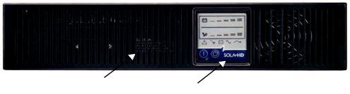
The SolaHD S4K2U-5C rack/tower models, in various power ratings, have the same general appearance, controls, and features (see Figure 1). The various rack/tower models di er largely in the receptacle type.
Ventilation Slots |
Operation and Display Panel |
|
Figure 1: S4K2U-5C rack/tower models—front view
1.3.2 Rear Panel Features
The rear panel of the S4K2U-5C has these features (see Figure 2):
•USB port
•Cooling fan
•Input receptacle
•Output receptacles
•Input circuit breaker
•IntelliSlot port
•Communication terminal block

S4K2U 5C SERIES USER MANUAL | 11
1000 VA models
IntelliSlot Port |
USB Port |
Input Circuit |
C14 Input Receptacle |
||
|
Breaker |
|
|
||
|
|
|
|
|
|
|
|
|
|
|
|
|
|
|
|
|
|
|
|
|
|
|
|
|
|
|
|
|
|
|
|
|
|
External |
|
Battery |
|
|
|||
|
|
|
|
|
|
|
|||||
|
|
|
|
|
|
|
|||||
|
|
|
|
|
|
|
|||||
|
|
|
|
|
|
|
|||||
Terminal Block |
|
|
|
|
|
||||||
|
|
Connector |
C13 Output Receptacles |
||||||||
Communication |
Cooling Fan |
||||||||||
|
|
|
|
|
|
|
|||||
2000 VA models
IntelliSlot Port USB Port |
Input Circuit |
C20 Input Receptacle |
|
Breaker |
|
||
|
|
|
|
|
|
|
|
|
|
|
|
|
|
|
|
|
|
|
|
|
|
|
|
|
|
|
|
|
|
|
|
|
|
|
|
|
|
|
|
|
|
|
|
|
|
|
|
|
|
|
|
|
|
|
|
|
|
|
|
|
|
|
|
|
|
|
|
|
|
|
|
|
|
|
|
|
|
|
|
|
|
|
External Battery |
|
|
||
Terminal Block |
Cooling Fan |
C13 Output Receptacles |
|||||||
Connector |
|||||||||
Communication |
|||||||||
|
|
|
|
|
|
||||
3000 VA models
IntelliSlot Port |
USB Port |
Input Circuit |
Output Circuit |
C20 Input Receptacle |
|||
|
Breaker |
|
|
Breakers |
|
|
|
|
|
|
|
||||
|
|
|
|||||
|
|
|
|
|
|
|
|
|
|
|
|
|
|
|
|
|
|
|
|
|
|
|
|
|
|
|
|
|
|
|
|
|
|
|
|
|
|
|
|
|
|
|
|
|
|
|
|
|
|
|
|
|
|
|
|
|
|
|
|
|
|
|
|
|
|
|
|
|
|
|
|
|
|
|
|
|
|
|
|
|
|
|
|
|
|
|
|
|
|
|
|
|
|
|
|
|
External Battery |
C13 Output |
|
|
|||
Terminal Block |
Cooling Fan |
C19 Output |
|||||||||
Connector |
|||||||||||
Communication |
Receptacles |
Receptacle |
|||||||||
|
|
|
|
||||||||
Figure 2: S4K2U-5C 230 V rack/tower models—rear panel components
12 | 1.0 Product Description
1.4 Major Components
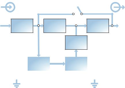
The operating principle of the UPS is illustrated in Figure 3.
Input |
Dynamic |
Output |
|
Bypass |
|
L1 |
SPD & EMI/ |
Rectifier / |
|
RFI Filters |
PFC |
||
|
Inverter |
L1 |
Dc-to-Dc
Converter
Battery |
|
Battery |
Charger |
|
|
|
|
|
|
|
|
L2/N L2/N
L2/N
G 
 G
G
Figure 3: Operating principle diagram
The UPS is composed of mains input, SPD and EMI/RFI lters, recti er/PFC, inverter, battery charger, dc-to-dc converter, battery, dynamic bypass, and UPS output.
1.4.1 Surge Protection Device (SPD) & EMI/RFI Filters
The S4K2U-5C has surge protection and lters that protect the connected load from power surges, electromagnetic interference (EMI), and radio frequency interference (RFI). These features can minimize any surges or interference present in the mains power. The lters also prevent surges or interference generated by the UPS from adversely a ecting devices connected on the same branch as the UPS.
1.4.2 Recti er/Power Factor Correction (PFC) Circuit
In normal operation, the S4K2U-5C’s recti er/power factor correction (PFC) circuit converts mains power to regulated dc power for use by the inverter, while ensuring that the wave shape of the input current used by the UPS is near ideal. Extracting this sine wave input current achieves two objectives:
•E cient power use by the UPS
•Reduced re ected harmonics
This results in cleaner power being available to other devices in the building not protected by the S4K2U-5C.

S4K2U 5C SERIES USER MANUAL | 13
1.4.3 Inverter
In normal operation, the S4K2U-5C’s inverter utilizes the dc output of the PFC recti er to produce precise, regulated sine wave ac power. When mains power fails, the inverter receives dc power from the dc-to-dc converter. In either operation mode, the UPS inverter is on-line, continuously generating clean, precise, regulated ac output power.
1.4.4 Battery Charger
The battery charger utilizes energy from the mains power and precisely regulates it to continuously oat charge the batteries. The batteries are being charged whenever the S4K2U-5C is plugged in, even when the UPS is not turned on.
1.4.5 Dc-to-Dc Converter
The dc-to-dc converter raises the dc voltage from the battery to the optimum operating voltage for the inverter. This allows the inverter to operate continuously at its optimum e ciency and voltage, thus increasing reliability.
1.4.6 Battery
The S4K2U-5C uses valve-regulated, non-spillable, lead acid batteries. To maintain battery design life, operate the UPS in an ambient temperature of 0°C to 25°C (32°F to 77°F).
NOTE: Optional external battery cabinets are available to extend battery run times.
1.4.7 Dynamic Bypass
The S4K2U-5C provides an alternate path for mains power to the connected loads in the unlikely event of a UPS malfunction. Should the S4K2U-5C have an overload, overtemperature, or UPS failure condition, the UPS automatically transfers the connected loads to bypass.
NOTE: The bypass power path does not protect the connected loads from disturbances on the mains.
1.5 Operating Modes
The UPS operating modes include: Mains (V ac) Mode, Bypass Mode, Battery Mode, Battery Recharge Mode, and Frequency Converter Mode. For descriptions of indicators and control buttons, refer to “3.0 Controls & Indicators”.
1.5.1 Mains (V ac) Mode
During Mains (V ac) Mode, mains power provides energy to the S4K2U-5C. The lters, PFC recti er, and the inverter process this power to provide computer-grade power to connected loads. Meanwhile, the UPS maintains the batteries in a fully charged state.
1.5.2 Manual Bypass Mode
Manual Bypass Mode occurs when the Standby/Manual Bypass button is pressed and held for about 2 seconds while the S4K2U-5C is in Mains (V ac) Mode. Bypass operation is indicated by an audible alarm and illuminated amber bypass indicator. (If other indicators are illuminated, refer to “8.0 Troubleshooting”). During Manual Bypass Mode, mains power bypasses the inverter and provides energy to the connected load.
! CAUTION
Turning o the UPS in Manual Bypass Mode will result in loss of output power and dropped loads.

14 | 1.0 Product Description
1.5.3 Battery Mode
The S4K2U-5C enters Battery Mode when mains power fails or is outside acceptable values. The battery system supplies power through the dc-to-dc converter to the inverter to generate clean ac power for the connected loads.
When the S4K2U-5C enters Battery Mode, the UPS sounds a half-second beep at 10-second intervals.
When approximately 2 minutes of run time remains, the beeps sound every 5 seconds to warn that the battery is getting low (this low battery warning is user-con gurable).
In Battery Mode, the Ac Input indicator goes o and the Battery Level indicators illuminate. Each Battery Level indicator represents a 20% capacity level. As capacity decreases, fewer indicators remain illuminated. Refer to “8.0 Troubleshooting”.
For approximate battery run times, refer to “9.0 Speci cations—Table 14”. The times in Table 14 are approximate. They are based on resistive loads and an ambient temperature of 25°C (77°F). To increase this time, turn o non-essential loads (such as idle computers and monitors) or add optional external battery cabinets.
! CAUTION
Turning o the S4K2U-5C while in Battery Mode will result in loss of output power. If the UPS is turned o manually, it must be manually restarted after mains power returns. If the UPS is turned o by a communication signal or because the batteries are depleted, it will operate as selected in the con guration program for Auto-Restart (refer to “5.2.1 Con guration Program”).
1.5.4 Battery Recharge Mode
Once mains power is applied to the S4K2U-5C, the battery charger begins charging the batteries.
1.5.5 Frequency Converter Mode
All models of the S4K2U-5C are capable of frequency conversion. Frequency Conversion Mode can be selected using the con guration program. Allowable frequency operating modes include:
•Auto Sensing — 50 Hz or 60 Hz — Bypass Enabled
•Auto Sensing — 50 Hz or 60 Hz — Bypass Disabled
•Frequency Converter — 50 Hz — Bypass Disabled
•Frequency Converter — 60 Hz — Bypass Disabled
NOTE: The default for all models of the S4K2U-5C is “Auto Sensing — 50 Hz or 60 Hz — Bypass Enabled.”
! CAUTION
Do not touch the ac input receptacle when the UPS is operating. Ac input voltages may still be present, even when the ac input indicator is o .
 Loading...