


 Loading...
UNIVERSAL MONITOR
Product Specification/Installation Sheet
Description
The Universal Monitor is a microprocessor with multisensing, remote monitoring and remote control capabilities. Its
advanced |
Universal Monitor |
technology |
Two sizes of enclosures |
provides high-
availability monitoring around the clock.
The Universal Monitor can operate as an independent, stand-alone controller or in conjunction with Liebert’s SiteScan Web Enterprise Monitoring System.
The enclosure of the Universal Monitor makes it suited for various applications in both new construction and retrofit jobs. The Universal Monitor can be mounted on a wall’s surface or recessed within a wall.
Features
•Custom configuration for specific applications
•Paging capability—up to four pager numbers
•Preconfigured on-board modem
•Alarm, Event and Trend logs with time and date stamp
•Battery backup to ensure alarm notification
•Backup and download configuration files
•User interface via RS232 or modem connection
•On-board audible alarm
•Configuration data and operating program permanently stored in nonvolatile Electrically Erasable Programmable Read Only Memory (EEPROM) for protection against power loss
•Real-time clock
•Status LEDs for verification and diagnostics
The keypad display on the face of the panel is a standard part of the Universal Monitor.
The display, the gateway to all configuration and monitoring, is password-protected.
The Universal Monitor has a standard, on-board modem for remote monitoring via a telephone line.
The modem is preconfigured to work with the panel, eliminating configuration and setup requirements.
Universal Monitor Components and Key Features
|
Power On/Off |
Battery |
Audible |
Common alarm |
Transformer |
switch |
pack |
horn |
connectors |
module*
24VAC |
|
|
|
|
TB5: |
|
|
|
|
|
|
(TERMINAL |
VIEW) |
|
|
power |
|
|
|
|
NO C NC |
C NC |
|
|
|
|
|
(TOP) |
(BOTTOM) |
|
|
connector |
|
|
|
|
+ |
OM |
|
|
24V INPUT |
|
|
|
AUDIBLE |
|
Manual |
LCD |
TB7: |
START |
|
|
ENABLE |
|
override |
|
|
|
|
Q11 |
|
||
contrast |
BATTERY |
BATTERY |
CODEARB |
LIEBERT |
|
|
switch |
adjustment |
LCD |
|
|
(outputs) |
|||
|
P23: |
|
|
|
|
|
|
|
|
CONTRAST |
|
|
|
|
|
|
|
|
|
|
|
TB3: |
Digital |
|
|
VBATT |
|
|
|
(BOTTOM) |
|
|
|
|
|
|
|
RELAY |
|
|
|
|
|
|
|
OUTPUTS |
output |
|
|
|
|
|
|
7 |
|
|
|
|
|
|
|
8 |
|
Modem |
|
|
|
|
|
6 |
connectors |
|
|
|
|
|
5 |
|
|
|
|
|
MODEM |
|
(BOTTOM) |
Digital |
|
|
|
|
|
|
|
7 |
|
|
|
|
|
4 |
|
8 |
|
24VAC |
|
|
|
|
|
5 |
input |
|
|
|
|
|
|
6 |
|
connector* |
|
|
|
|
|
|
connectors |
ASS |
TB2: |
CONTACT |
|
|
INPUTS |
|
|
|
|
1-2 TOP |
|
|
Analog |
|
|
|
|
3-4 BOTTOM |
|
|
|
Power |
ON |
|
|
|
|
|
input |
J11: PHONE |
MODEM |
|
|
|
|
||
On/Off |
PIN 4-RING |
(TOP) + — |
+ — + — |
AG |
TB9: ANALOG |
CLASS 2 |
connectors |
|
PIN 3-TIP |
422 |
|
ALL CIRCUITS: |
|||
switch* |
TB10: COMMS 485 |
|
|
|
|
||
|
(BOTTOM) + — |
+ — + — |
|
GROUND |
|
|
|
Power |
|
|
|
receptacle* Phone line |
Serial interface |
EIA485 |
SiteScan Web |
connector |
connector (RS232/EIA574) |
connector |
connector (EIA422) |
*Transformer module comes standard in large enclosure only
1
Hardware and Components
Two sizes of enclosures provide flexibility and expansion to meet evolving application needs. Both sizes of enclosures come standard with a liquid crystal display (LCD) and controller board. In addition, the large Universal Monitor has an internal Transformer Module.
The enclosure features a key lock for added security and is made of metal to accommodate secure conduit fittings and protect components against environmental debris. The enclosure is designed for easy wire routing and terminations, with top and bottom access slots for communication cables and network wires. The enclosure is 2-3/4" deep, allowing for recess mounting in a wall.
Keypad Display
The keypad display is a user interface mounted on the enclosure door of each Universal Monitor. The display provides for complete monitoring and
configuration of the panel and is Keypad password-protected.
The keypad display provides the ability for the Universal Monitor to operate as a complete standalone panel.
Controller Board
The controller board supports 22 points:
•Eight digital inputs
•Four analog inputs
•Eight digital outputs
•Two Common Alarm outputs
The digital inputs are dry contacts. The analog inputs are 4-20mA inputs. The digital outputs and Common Alarm outputs are Form C contact relays.
Transformer Module
The large Universal Monitor comes with either 115VAC or 230VAC Transformer Module.
• The 115VAC Transformer Module provides step-down power from 115VAC to 24VAC, two Class 2 24VAC 40VA power terminations and one 115VAC outlet to power accessory devices, such as a Portable Operator’s Terminal.
• The 230VAC Transformer
Module provides step-down power from 230VAC to 24VAC and two Class 2 24VAC 40VA power terminations. An outlet is not provided on this Transformer Module.
The Transformer Module may be ordered separately as an option for the small Universal Monitor—or any device requiring 24VAC—and mounted outside the enclosure.
The point terminations are made using removable terminal blocks. This allows for easier access to the terminators, streamlining the process of connecting external devices to the Universal Monitor.
The battery supplies power to the modem for a minimum of 10 minutes, providing the capability to send out a loss-of-power alarm to all configured pagers.
Flash ROM may be easily upgraded at the job site, simplifying the process of installing new firmware as it becomes available.
An RS232 operator terminal port is included with each controller board for easy interface to a laptop or desktop PC for setup and device monitoring.
An integrated on-board modem is included with each controller board for remote access to the Universal Monitor. An RJ11 phone modem jack is also included. The modem is factory-configured, eliminating field configuration and wiring requirements.
An IGM422 connection is included with each controller to connect the Universal Monitor to Liebert’s SiteScan Web Enterprise Monitoring System. This connection allows information and alarms to be monitored from a centrally located command center.
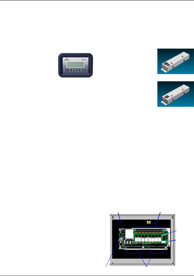
I/O Expansion Module
The Universal Monitor I/O Expansion Module, purchased separately, has connectors for 16 digital inputs and eight digital outputs, as shown below. The board has light emitting diodes (LEDs) to display the status of monitored output devices, communications ports for connection to the Universal Monitor, power connections and other features necessary to monitor and protect your operation.
I/O Expansion Module Components
& Key Features
24VAC power |
Digital output |
connector |
connectors (8) |
|
|
|
|
|
|
|
|
|
|
|
USE COPPER (CU) CONDUCTORS ONLY. |
Digital |
|
POWER INPUT |
|
|
|
|
|
RELAY OUTPUTS |
|
|
|||
|
|
|
|
|
|
|
|
|
|
|
|
output |
|
|
|
3065-810 |
168AOMultiflex |
|
|
|
|
|
|
|
fuses (8) |
|
|
|
|
|
|
|
|
|
|
|
||
|
|
|
|
V1 |
|
V3 |
V7 |
|
V9 |
V13 |
V15 |
|
EIA485 + (to UM-) |
|
|
|
|
|
|
|
|
|
|
|
Digital |
0V |
S4 |
S3 |
S2 |
S1 |
|
|
|
|
|
|
|
|
EIA485 - (to UM+) |
|
|
|
|
|
|
|
|
|
|
|
output |
|
|
|
|
K1 |
K2 |
K3 |
K4 |
K5 |
K6 |
K7 |
K8 |
|
|
|
|
|
|
|
OUT2 |
|
|
OUT6 |
OUT7 |
OUT8 |
|
|
|
|
|
|
|
|
|
|
|
|
|
DIP |
|
|
|
|
|
|
|
|
|
|
|
|
switch |
DEFAULT SETTINGS FOR USE WITH UNIVERSAL MONITOR |
|
|
|
|
|
|
|
|
|
|
||
EIA485 connector |
Digital input connectors (16) |
2
Loading...