


READ AND SAVE THESE INSTRUCTIONS
Ceiling Fan/Light
Receiver & Reverse Module
Owner's Manual
For Use With SR600 Remote Control, SR650 Remote Control and SW605 Wall Control
Receiver Model Numbers:
RCK55
6-Speed Receiver
RCK55 Receiver Supplied with Reverse Module for K55 Motor Fans
The RCK55 Receiver and Module for Use Only with Emerson Ceiling Fan Models: CF4800, CF4500, CF2400,CF2000,
CF3900, CF3600, & CF1.
Part No. F40BP74160000 |
Form No. BP7416 |
!WARNING
Safety Instructions
WARNING: To avoid fire, shock, and serious personal injury, follow all instructions carefully.
1.Read your Owner's Manual carefully before installing the Receiver. Retain Owner's Manual for future reference.
2.Before servicing or cleaning the ceiling fan, switch power off at service panel and lock service panel to prevent power from being switched on accidentally. When the service disconnecting means cannot be locked, securely fasten a warning device such as a tag, to the service panel.
ADDITIONAL SAFETY INSTRUCTIONS FOR INSTALLATION
1.To avoid possible electrical shock, be sure electricity is turned off at the main fuse or circuit breaker box before wiring.
2.Make certain no bare wires are exposed outside the wire connectors.
3.All wiring must conform to National and Local Electrical Codes.
4.Follow the recommended instructions for the proper method of wiring your new Receiver. If you feel you do not have enough electrical wiring knowledge or experience, have your Receiver installed by a licensed electrician. Any electrical work not described in this manual should be performed by a licensed electrician.
INSTRUCTION TO THE USER (if device contains a digital device)
This equipment has been tested and found to comply with the limits for a class B digital device, pursuant to part 15 of the FCC Rules. These limits are designed to provide reasonable protection against harmful interference in a residential installation. This equipment generates, uses and can radiate radio frequency energy and if not installed and used in accordance with the instructions, may cause harmful interference to radio communications. However, there is no guarantee that interference will not occur in a particular installation. If this equipment does cause harmful interference to radio or television reception, which can be determined by turning the equipment off and on, the user is encouraged to try to correct the interference by one or more of the following measures:
•Reorient or relocate the receiving antenna.
•Increase the separation between the equipment and receiver.
•Connect the equipment into an outlet on a circuit different from that to which the receiver is connected.
•Consult the dealer or an experienced radio/TV technician for help.
This equipment has been certified to comply with the limits for a class B computing device, pursuant to FCC Rules. In order to maintain compliance with FCC regulations, shielded cables must be used with this equipment. Operation with non-approved equipment or unshielded cables is likely to result in interference to radio and TV reception. The user is cautioned that changes and modifications made to the equipment without the approval of manufacturer could void the user’s authority to operate this equipment.
This Class B digital apparatus meets all requirements of the Canadian
Interference-Causing Equipment Regulations.
DATE CODE:
The date code of this fan may be found on the box, stamped in ink on a white label. You should record this data above and keep it in a safe place for future use.
2
General
Your Emerson Ceiling Fanl may be used with a SR600 or SR650 Remote Control, a SW605 Wall Control, and a RCK55 6- speed Receiver. The remote control or wall control is designed to control your ceiling fan speed, airflow direction, and light intensity.
NOTE: The RCK55 Receiver and Module for Use Only with Emerson Ceiling Fan Models: CF4800, CF4500, CF2400,CF2000, CF3900, CF3600, & CF1.
Unpackaging
The carton with the RCK55 Receiver also contains a reversing module, seven wire connectors, four pull chain switch plugs, and two rectangular switch plugs.
The carton with the SR650 Remote Control contains a storage bracket with two mounting screws.
The carton with the SW605 Wall Control contains three switch covers; ivory, white and almond color.
IMPORTANT
This Owner’s Manual is divided into three sections. The first section, SR600/SR650 REMOTE CONTROL PROCEDURES, describes how to install the two AAA alkaline batteries in the SR600 remote control transmitter and the two CR2032 Lithium batteries in the SR650 remote control transmitter, and how to set the operating frequency of the transmitter and receiver. The second section describes how to install the SW605 Wall Control. These instructions must be performed prior to installation of the ceiling fan as described in the third section, CEILING FAN PROCEDURES.
SECTION ONE:
SR600 REMOTE
CONTROL PROCEDURES
General
Your Emerson Ceiling Fan/Light SR600 Remote Control consists of hand-held transmitter and a receiver which is mounted under the fan ceiling cover. The remote control is designed to separately control your ceiling fan speed and light intensity.
The remote control transmitter is powered by two AAA alkaline batteries (not included). To prevent possible damage if the batteries should leak, be sure to remove the batteries when the control is not to be used for an extended period of time.
Code switches in the transmitter and receiver may be set in 32 different positions. If your fan and light go on and off without using your control, you may be getting interference from other remote units such as garage door openers, car alarms or security systems. To remedy this situations, simply change the combination code in your transmitter and receiver.
Preset Memory Feature
Your Emerson receiver is equipped with a preset memory feature. If the AC supply to the receiver is powered through a wall switch, when the switch is turned OFF, the control will remember the light intensity and fan speed. When the switch is turned back ON the light and fan will resume operation as they were prior to the switch being turned OFF.
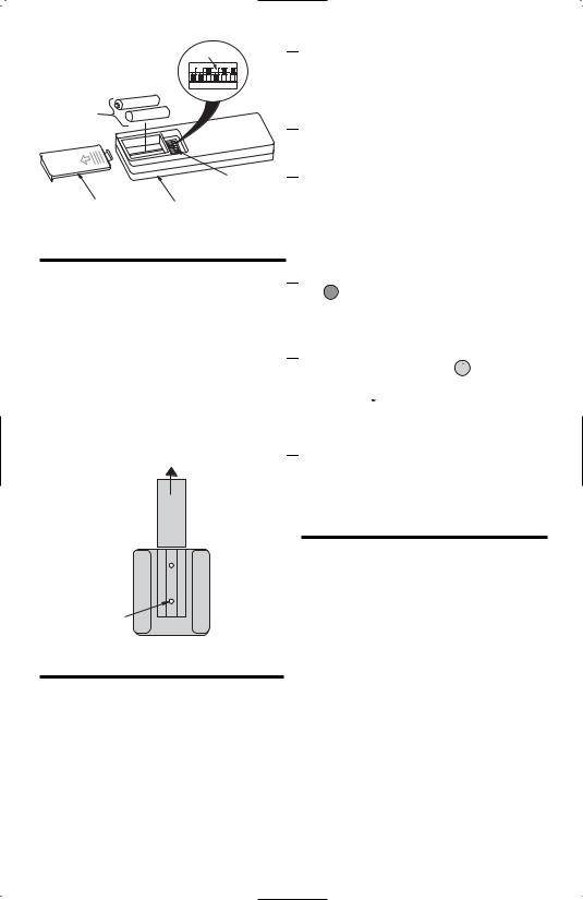
Installation of Battery
1.Remove the battery cover by pressing firmly below the arrow and sliding the cover off the control (Figure 1).
2.Install two AAA alkaline batteries and reinstall the battery cover.
3
REMOTE CONTROL
LEVERS
|
|
|
|
|
ON |
1 |
2 |
3 |
4 |
5 |
I |
TWO AAA
BATTERIES
CODE
SWITCHES
BATTERY |
SR600 REMOTE |
|
COMPARTMENT |
||
CONTROL |
||
COVER |
||
|
Figure 1

 1. Slide the five switch levers in the remote control to your choice of ON (up) or down positions. Use a ball-point pen or small screwdriver and slide the levers firmly up or down.

 2. When power is restored, push and hold the fan OFF button (
  ) for 3 to 5 seconds to set the code in the receiver.

 3. If airflow is desired in the opposite direction, press the (
 ) button on the wall control. The fan must be operating at any speed for the reverse button to function. The blades will turn in the opposite direction and reverse the airflow.
Installation of Storage Bracket for SR600 Remote Control
A storage bracket is provided for holding your remote control when not in use. If you desire to use the bracket, install it on a wall that is away from excess heat or humidity (Figure 2).
TO INSTALL BRACKET TO WALL:
SLIDE THE COVER UP TO EXPOSE THE SCREW HOLES FOR INSTALLATION
COVER 
WALL
BRACKET
SCREW
HOLES (2)
Figure 2
Setting Operating
Frequency of SR600
Remote Control
Your remote control has code switches which must be set in one of 32 possible code combinations. The five levers (numbered 1, 2, 3, 4, and 5) on the switches are factory-set in the ON (up) position. Change the switch settings as follows:

 4. To set the desired fan speed, press the (
  ) button to decrease the speed and the (
  ) to increase the speed. The LED display will light up to indicate the new speed selected.

 5. To set the light intensity, press and release the LIGHT (
  ) button to decrease the light intensity and the LIGHT (
 ) button to increase the light intensity. The light will turn on at the light intensity previously selected.

 6. The sixth switch marked ON and I is for dimming control of lights: Set switch to ON to allow for dimming of the lights. Set switch to I for no dimming of the lights such as for fluorescent bulbs.
SR650 REMOTE
CONTROL PROCEDURES
General
Your Emerson Ceiling Fan/Light SR650 Remote Control consists of hand-held transmitter with wall mount and a receiver which is mounted under the fan ceiling cover. The remote control is designed to separately control your ceiling fan speed and light intensity.
The remote control transmitter is powered by two CR2032 Lithium batteries (included). Be sure to remove the batteries when the control is not to be used for an extended period of time.
Code switches in the transmitter and receiver may be set in 32 different positions. If your fan and light go on and off without using your control, you may be
4
getting interference from other remote units such as garage door openers, car alarms or security systems. To remedy this situations, simply change the combination code in your transmitter and receiver.
Preset Memory Feature
Your Emerson receiver is equipped with a preset memory feature. If the AC supply to the receiver is powered through a wall switch, when the switch is turned OFF, the control will remember the light intensity and fan speed. When the switch is turned back ON the light and fan will resume operation as they were prior to the switch being turned OFF.
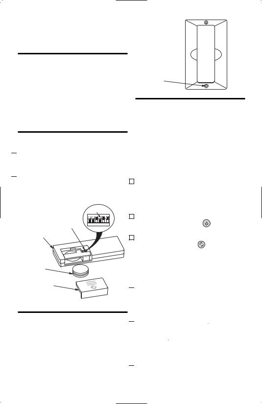
Installation of Battery

 1. Remove the battery cover by pressing firmly below the arrow and sliding the cover off the control (Figure 3).

 2. Install one CR2032 Lithium battery into
WALL
BRACKET
SCREW
HOLES (2)
Figure 4
Setting Operating
Frequency of SR650
Remote Control
Your remote control has code switches which must be set in one of 32 possible code combinations. The five levers (numbered 1, 2, 3, 4, and 5) on the switches are factory-set in the ON (up) position. Change the switch settings as follows:
the battery compartment then stack the |
1. Slide the five switch levers in the |
|
other CR2032 Lithium battery on top of |
remote control to your choice of ON |
|
the installed battery and reinstall the |
(up) or down positions. Use a ball-point |
|
battery cover. |
pen or small screwdriver and slide the |
|
levers firmly up or down. |
||
REMOTE CONTROL |
||
LEVERS |
|
|
|
|
|
|
|
ON |
2. When power is restored, push and hold |
|
CODE |
1 |
2 |
3 |
4 |
5 |
I |
the fan OFF button ( |
) for 3 to 5 |
SWITCHES |
|
|
|
|
|
|
seconds to set the code in the receiver. |
|
SR650 REMOTE |
|
|
3. If airflow is desired in the opposite |
||||
CONTROL |
|
|
|||||
|
|
|
direction, press the ( |
) button on the |
|||
|
|
|
wall control. The fan must be operating |
||||
TWO CR2032 |
|
|
at any speed for the reverse button to |
||||
|
|
function. The blades |
will |
turn in |
the |
||
LITHIUM |
CR2 |
032 |
|||||
BATTERIES |
|
0 |
opposite direction and |
reverse |
the |
||
CR2 |
32 |
||||||
|
|
|
|
|
|||
(stacked) |
airflow. |
|
BATTERY COMPARTMENT COVER
Figure 3

 4. To set the desired fan speed, press the (
 ) button to decrease the speed and the (
  ) to increase the speed. The LED display will light up to indicate the new speed selected.
Installation of Storage
Bracket for SR650
Remote Control
A storage bracket is provided for holding your remote control when not in use. If you desire to use the bracket, install remote control storatge bracket using the two screws provided. Install on a wall that is away from excess heat or humidity (Figure 4).

 5. To set the light intensity, press and release the LIGHT (
  ) button to decrease the light intensity and the LIGHT (
 ) button to increase the light intensity. The light will turn on at the light intensity previously selected.

 6. The sixth switch marked ON and I is for
|
dimming control of lights: Set switch to |
|
ON to allow for dimming of the lights. |
|
Set switch to I for no dimming of the |
5 |
lights such as for fluorescent bulbs. |
 Loading...