


Instruction Manual |
A81 Valve |
D103302X012 |
May 2011 |
|
|
Fisherr POSI SEAL™ A81 Rotary Valve
Contents |
Figure 1. Fisher A81 Valve with FieldQ™ Actuator |
Introduction . . . . . . . . . . . . . . . . . . . . . . . . . . . . . . . . . . |
. 1 |
Scope of Manual . . . . . . . . . . . . . . . . . . . . . . . . . . . |
. 1 |
Specifications . . . . . . . . . . . . . . . . . . . . . . . . . . . . . . . |
2 |
Description . . . . . . . . . . . . . . . . . . . . . . . . . . . . . . . . . |
2 |
Installation . . . . . . . . . . . . . . . . . . . . . . . . . . . . . . . . . . . . |
4 |
Maintenance . . . . . . . . . . . . . . . . . . . . . . . . . . . . . . . . . . |
8 |
Packing Maintenance . . . . . . . . . . . . . . . . . . . . . . . . |
9 |
Replacing the Seal Ring Assembly . . . . . . . . . . . . . . |
12 |
Replacing the Disk, Shafts, or Bearings . . . . . . . . . . |
13 |
Actuator Mounting . . . . . . . . . . . . . . . . . . . . . . . . . |
18 |
Parts Ordering . . . . . . . . . . . . . . . . . . . . . . . . . . . . . . . . |
18 |
Parts Kits . . . . . . . . . . . . . . . . . . . . . . . . . . . . . . . . . . . |
19 |
Parts List . . . . . . . . . . . . . . . . . . . . . . . . . . . . . . . . . . . |
20 |
W9479
Introduction
Scope of Manual
This instruction manual includes installation, maintenance, and parts information for the Fisher POSI SEAL A81 valve, DN50 through DN300 or NPS 2 through NPS 12 (figure 1). Refer to separate instruction manuals for information covering the power on off actuator and accessories.
Do not install, operate, or maintain an A81 valve without being fully trained and qualified in valve, actuator, and accessory installation, operation, and maintenance. To avoid personal injury or property damage, it is important to carefully read, understand, and follow all the contents of this manual, including all safety cautions and warnings. If you have any questions about these instructions, contact your Emerson Process Management sales office before proceeding.
www.Fisher.com
A81 Valve |
|
|
|
|
|
|
|
|
|
Instruction Manual |
|||||||
May 2011 |
|
|
|
|
|
|
|
|
|
|
D103302X012 |
||||||
|
|
|
|
|
|
|
|
|
|
|
|
|
|
|
|
||
Table 1. Fisher A81 Valve Specifications |
|
|
|
|
|
|
|
|
|
|
|||||||
|
|
|
|
|
|
|
|
|
|
|
|
|
|
|
|
|
|
|
Specifications |
|
|
|
EN |
|
|
|
|
|
ASME |
|
|||||
|
Valve Body Size |
|
|
DN 50, 80, 100, 150, 200, 250, and 300 |
|
|
NPS 2, 3, 4, 6, 8, 10, and 12 |
|
|||||||||
|
|
|
|
|
|
|
|
|
|
|
|
|
|
|
|
||
|
Pressure Rating |
|
|
PN 10 to 40 per EN 12516 1 |
|
|
CL150 and 300 per ASME B16.34 |
|
|||||||||
|
|
|
|
|
|
|
|
|
|
|
|
|
|
|
|
|
|
|
|
|
|
|
|
|
|
EN 1.0619 steel |
|
|
|
|
WCC steel |
|
|||
|
|
|
|
|
|
|
|
|
|
|
|
|
|
|
|
||
|
Valve Body Materials |
|
|
EN 1.4409 stainless steel |
|
|
CF3M (316L) stainless steel |
|
|||||||||
|
|
|
|
|
|
|
|
|
|
|
|
|
|
||||
|
|
|
|
CW2M(1) |
|
|
|
|
CW2M(1) |
|
|||||||
|
|
|
|
|
|
|
|
|
|
|
|
|
|||||
|
|
|
|
|
|
|
|
M35 2(4) |
|
|
|
|
M35 2 |
|
|||
|
|
|
|
|
|
|
EN 1.4409 stainless steel |
|
|
CF3M stainless steel |
|
||||||
|
|
|
PTFE or RPTFE |
|
|
|
|
|
|
|
|
|
|
|
|
||
|
|
|
|
|
CW2M |
|
|
|
|
CW2M |
|
||||||
|
|
|
Seal(3) |
|
|
|
|
|
|
|
|||||||
Disk Materials |
|
|
|
|
|
|
|
|
|
|
|
|
|||||
|
|
M35 2 |
|
|
|
|
M35 2 |
|
|||||||||
|
|
|
|
|
|
|
|
|
|
||||||||
|
|
|
|
|
|
|
|
|
|
|
|
|
|
|
|
|
|
|
|
|
Metal or |
|
Chrome plated EN 1.4409 Stainless Steel |
|
|
Chrome plated CF3M Stainless Steel |
|||||||||
|
|
|
UHMWPE(2) Seal |
|
|
|
|||||||||||
|
|
|
|
|
|
|
|
|
|
|
|
|
|
|
|||
|
End Connections |
|
|
Mates with raised face flanges |
|
|
Mates with raised face flanges |
|
|||||||||
|
|
|
|
per EN 1092 1 |
|
|
|
per ASME B16.5 |
|
||||||||
|
|
|
|
|
|
|
|
|
|
|
|
||||||
|
|
|
|
|
|
|
|
|
|
|
|
|
|
|
|
||
|
Valve Body Style |
|
|
|
Wafer (flangeless) and single flange with tapped or through holes |
|
|||||||||||
|
|
|
|
|
|
|
|
|
|
|
|
|
|||||
Face to Face Dimensions |
|
|
|
Meets MSS SP68, API 609, and EN 558 standards |
|
||||||||||||
|
|
|
|
|
|
|
|
|
|
|
|
|
|
|
|||
|
|
|
|
|
|
|
|
PTFE, RPTFE, or UHMWPE seal ring No visible leakage per MSS SP 61 |
|
||||||||
|
|
|
|
|
|
|
|
|
|
|
|
|
|
||||
|
|
Shutoff |
|
|
|
S31600 (316 SST) seal ring - 0.1 scfh per unit of NPS (NPS 6 valve = 0.6 scfh) |
|
||||||||||
|
|
|
|
|
|
|
|
|
|
|
per MSS SP-61 |
|
|
|
|
|
|
|
|
|
|
|
|
|
|
|
|
|
|
|
|
||||
|
Flow Direction |
|
Standard (forward flow) is with the seal retainer facing upstream; reverse flow is permissible within specified |
||||||||||||||
|
|
|
|
|
|
pressure drop limitations |
|
|
|
|
|||||||
|
|
|
|
|
|
|
|
|
|
|
|
|
|
||||
|
|
|
|
|
|
|
|
|
|
|
|
|
|
|
|
||
|
Flow Characteristic |
|
|
|
|
|
Approximately linear |
|
|
|
|
||||||
|
|
|
|
|
|
|
|
|
|
|
|
|
|
||||
|
Disk Rotation |
|
|
Counterclockwise to open (when viewed from actuator side of valve body) through 90 degrees of disk |
|||||||||||||
|
|
|
|
|
|
|
rotation |
|
|
|
|
|
|||||
|
|
|
|
|
|
|
|
|
|
|
|
|
|
|
|
||
|
|
|
|
|
|
|
|
|
|
|
|
|
|
|
|||
1. This material is not listed in EN 12516-1 or ASME B16.34. See table 4 for pressure/temperature ratings. |
|
|
|
|
|
|
|
||||||||||
2. UHMWPE stands for ultra high molecular weight polyethylene. |
|
|
|
|
|
|
|
|
|
|
|||||||
3. RPTFE is a reinforced PTFE seal. |
|
|
|
|
|
|
|
|
|
|
|
|
|
||||
4. This material is not listed in EN 12516-1. See table 4 for pressure/temperature ratings. |
|
|
|
|
|
|
|
|
|||||||||
|
|
|
|
|
|
|
|
|
|
|
|
|
|
|
|
||
Table 2. Valve Size, Shaft Diameter, and Approximate Weight |
|
|
|
|
|
|
|
|
|||||||||
|
|
|
|
|
|
|
|
|
|
|
|
|
|
|
|
|
|
|
VALVE SIZE |
|
PRESSURE RATING |
SHAFT DIAMETER |
|
|
APPROXIMATE WEIGHT |
|
|||||||||
|
|
|
Wafer Style |
|
Single Flange |
||||||||||||
|
|
|
|
|
|
|
|
|
|
|
|
|
|||||
DN |
|
NPS |
|
EN |
|
ASME |
mm |
|
Inches |
kg |
Pounds |
|
kg |
|
Pounds |
||
50 |
|
2 |
|
PN10 40 |
|
CL150/300 |
12.7 |
|
1/2 |
4.7 |
10 |
|
6.7 |
|
15 |
||
|
|
|
|
|
|
|
|
|
|
|
|
|
|
|
|
||
80 |
|
3 |
|
PN10 40 |
|
CL150/300 |
15.9 |
|
5/8 |
7.5 |
17 |
|
11.2 |
|
25 |
||
|
|
|
|
|
|
|
|
|
|
|
|
|
|
|
|
||
100 |
|
4 |
|
PN10 40 |
|
CL150/300 |
19.1 |
|
3/4 |
12.5 |
28 |
|
17.6 |
|
39 |
||
|
|
|
|
|
|
|
|
|
|
|
|
|
|
|
|
||
150 |
|
6 |
|
PN10 40 |
|
CL150/300 |
25.4 |
|
1 |
15.7 |
35 |
|
26.5 |
|
58 |
||
|
|
|
|
|
|
|
|
|
|
|
|
|
|
|
|
|
|
200 |
|
8 |
|
PN10 16 |
|
CL150 |
31.8 |
|
1 1/4 |
30.2 |
67 |
|
40.2 |
|
89 |
||
|
|
|
|
|
|
|
|
|
|
|
|
|
|
|
|||
|
|
PN25 40 |
|
CL300 |
31.8 |
|
1 1/4 |
33.9 |
75 |
|
46.0 |
|
102 |
||||
|
|
|
|
|
|
|
|
|
|||||||||
|
|
|
|
|
|
|
|
|
|
|
|
|
|
|
|
|
|
250 |
|
10 |
|
PN10 16 |
|
CL150 |
31.8 |
|
1 1/4 |
38.9 |
86 |
|
50.5 |
|
111 |
||
|
|
|
|
|
|
|
|
|
|
|
|
|
|
|
|||
|
|
PN25 40 |
|
CL300 |
31.8 |
|
1 1/4 |
51.8 |
114 |
|
79.2 |
|
175 |
||||
|
|
|
|
|
|
|
|
|
|||||||||
|
|
|
|
|
|
|
|
|
|
|
|
|
|
|
|
|
|
300 |
|
12 |
|
PN10 16 |
|
CL150 |
38.1 |
|
1 1/2 |
68.7 |
151 |
|
98.3 |
|
217 |
||
|
|
|
|
|
|
|
|
|
|
|
|
|
|
|
|||
|
|
PN25 40 |
|
CL300 |
38.1 |
|
1 1/2 |
76.6 |
169 |
|
104.6 |
|
231 |
||||
|
|
|
|
|
|
|
|
|
|||||||||
|
|
|
|
|
|
|
|
|
|
|
|
|
|
|
|
|
|
Description
The A81 rotary valve with FieldQ rack and pinion actuator offers automated on off, quarter turn performance. FieldQ is available in spring return and double acting piston designs.
The valve body meets PN 10 through PN 40, CL150, and CL300 ratings. Face to face dimensions meet EN 558, API 609, and MSS SP68 standards. Retainer clips provide for versatility to mount and align the same wafer style valve body in different piping configurations (ASME and EN ratings).
2

Instruction Manual |
A81 Valve |
D103302X012 |
May 2011 |
|
|
The A81 rotary valve features an eccentrically mounted disk with either soft or metal seal, providing capability for enhanced shutoff. The interchangeable sealing technology allows for the same valve body to accept both soft and metal seals.
Table 3. Material Temperature Capabilities
|
|
MATERIAL |
|
|
TEMPERATURE |
|
||
|
|
|
|
|
|
LIMITS(1) |
|
|
|
|
|
EN Materials |
|
|
|
|
|
Valve Body |
Shaft |
Bearing Lining and Jacket |
Seal |
Packing |
_C |
|
_F |
|
1.0619 Steel |
S17400 or |
PEEK / PTFE |
PTFE or RPTFE |
PTFE or Graphite |
–10 to 232 |
|
14 to 450 |
|
|
S20910 |
|
|
|
|
|
|
|
|
|
UHMWPE |
PTFE or Graphite |
–10 to 93 |
|
14 to 200 |
|
|
|
|
|
|
|
||||
|
|
|
|
|
|
|
|
|
|
|
|
Metal |
PTFE or Graphite |
–10 to 232 |
|
14 to 450 |
|
|
|
|
|
|
|
|
|
|
|
|
R30006 (Alloy 6) or S31600 |
Metal |
Graphite |
–10 to 400(2) |
|
14 to 752(2) |
|
|
|
Nitride |
|
|
|
|
|
|
|
|
|
|
|
|
|
|
|
1.4409 |
S20910 |
PEEK / PTFE |
PTFE or RPTFE |
PTFE or Graphite |
–10 to 232 |
|
14 to 450 |
|
Stainless |
|
|
|
|
|
|
|
|
|
|
UHMWPE |
PTFE or Graphite |
–10 to 93 |
|
14 to 200 |
|
|
Steel |
|
|
|
|
||||
|
|
|
|
|
|
|
|
|
|
|
Metal |
PTFE or Graphite |
–10 to 232 |
|
14 to 450 |
|
|
|
|
|
|
|
||||
|
|
|
|
|
|
|
|
|
|
|
R30006 (Alloy 6) or S31600 |
Metal |
Graphite |
–10 to 500(2) |
|
14 to 932(2) |
|
|
|
Nitride |
|
|
|
|
|
|
|
|
|
|
|
|
|
|
|
CW2M |
N10276 |
PEEK / PTFE |
PTFE or RPTFE |
PTFE |
–10 to 232 |
|
14 to 450 |
|
|
|
|
|
|
|
|
|
|
M35 2 |
N05500 |
PEEK / PTFE |
PTFE or RPTFE |
PTFE |
–10 to 232 |
|
14 to 450 |
|
|
|
|
|
|
|
|
|
|
|
|
|
ASME Materials |
|
|
|
|
|
Valve Body |
Shaft |
Bearing Lining and Jacket |
Seal |
Packing |
_C |
|
_F |
|
WCC steel |
S17400 or |
PEEK / PTFE |
PTFE or RPTFE |
PTFE or Graphite |
–29 to 232 |
|
-20 to 450 |
|
|
S20910 |
|
|
|
|
|
|
|
|
|
UHMWPE |
PTFE or Graphite |
–18 to 93 |
|
0 to 200 |
|
|
|
|
|
|
|
||||
|
|
|
|
|
|
|
|
|
|
|
|
Metal |
PTFE or Graphite |
–29 to 232 |
|
-20 to 450 |
|
|
|
|
|
|
|
|
|
|
|
|
R30006 (Alloy 6) or S31600 |
Metal |
Graphite |
–29 to 427(2) |
|
-20 to 800(2) |
|
|
|
Nitride |
|
|
|
|
|
|
|
|
|
|
|
|
|
|
|
CF3M |
S20910 |
PEEK / PTFE |
PTFE or RPTFE |
PTFE or Graphite |
–46 to 232 |
|
–50 to 450 |
|
Stainless |
|
|
|
|
|
|
|
|
|
|
UHMWPE |
PTFE or Graphite |
–18 to 93 |
|
0 to 200 |
|
|
Steel |
|
|
|
|
||||
|
|
|
|
|
|
|
|
|
|
|
Metal |
PTFE or Graphite |
–46 to 232 |
|
–50 to 450 |
|
|
|
|
|
|
|
||||
|
|
|
|
|
|
|
|
|
|
|
R30006 (Alloy 6) or S31600 |
Metal |
Graphite |
–46 to 454(2) |
|
–50 to 850(2) |
|
|
|
Nitride |
|
|
|
|
|
|
|
|
|
|
|
|
|
|
|
CW2M |
N10276 |
PEEK / PTFE |
PTFE or RPTFE |
PTFE |
–46 to 232 |
|
–50 to 450 |
|
|
|
|
|
|
|
|
|
|
M35 2 |
N05500 |
PEEK / PTFE |
PTFE or RPTFE |
PTFE |
–46 to 232 |
|
–50 to 450 |
|
|
|
|
|
|
|
|
|
|
1. Minimum allowable temperature for PN series flanges is -10_C (14_F). See requirements of EN 13445 2 Annex B for applications below -10_C (14_F) with PN series flanges. 2. For applications exceeding 316_C (600_F), consult your Emerson Process Management sales office for appropriate disk material selection.
Table 4. Maximum Allowable Inlet Pressure for CW2M and M35 2 Valves
TEMPERATURE |
|
|
CW2M(1) |
|
|
|
M35 2(3) |
|
|
||||
150(2) |
300(2) |
PN 10(2) |
|
PN 16(2) |
PN 25(2) |
PN 40(2) |
PN 10(2) |
PN 16(2) |
|
PN 25(2) |
PN 40(2) |
|
|
|
|
|
|
||||||||||
_C |
|
|
|
Bar |
|
|
|
|
Bar |
|
|
||
–46 to 38 |
20.0 |
51.7 |
10.0 |
|
16.0 |
25.0 |
40.0 |
9.3 |
15.2 |
|
23.8 |
37.9 |
|
50 |
19.5 |
51.7 |
9.9 |
|
15.9 |
24.8 |
39.6 |
9.3 |
15.2 |
|
23.8 |
37.9 |
|
100 |
17.7 |
51.5 |
9.4 |
|
15.1 |
23.6 |
37.8 |
9.3 |
15.1 |
|
23.7 |
37.8 |
|
150 |
15.8 |
50.3 |
9.4 |
|
15.1 |
23.6 |
37.8 |
9.3 |
14.8 |
|
23.4 |
37.2 |
|
200 |
13.8 |
48.3 |
9.1 |
|
14.6 |
22.9 |
36.6 |
9.0 |
14.5 |
|
22.5 |
36.3 |
|
232 |
12.7 |
47.0 |
9.1 |
|
14.6 |
22.9 |
36.6 |
9.0 |
14.5 |
|
22.4 |
36.2 |
|
|
|
|
|
|
|
|
|
|
|
|
|
|
|
_F |
|
|
|
Psig |
|
|
|
|
Psig |
|
|
||
–50 to 100 |
290 |
750 |
145 |
|
232 |
362 |
580 |
135 |
220 |
|
345 |
550 |
|
200 |
260 |
750 |
144 |
|
230 |
359 |
575 |
135 |
220 |
|
345 |
540 |
|
300 |
230 |
730 |
137 |
|
219 |
342 |
548 |
135 |
215 |
|
340 |
525 |
|
400 |
200 |
700 |
133 |
|
212 |
331 |
530 |
130 |
210 |
|
325 |
525 |
|
450 |
185 |
680 |
133 |
|
212 |
331 |
530 |
130 |
210 |
|
325 |
525 |
|
|
|
|
|
|
|
|
|
|
|
|
|
|
|
1. This material is not listed in EN 12516 1 or ASME B16.34. Also see the Installation section.
2. The designations PN or 150 and 300 are used only to indicate relative pressure retaining capabilities and are not EN or ASME pressure temperature rating class designations. 3. This material is not listed in EN 12516-1. Also see the Installation section.
3

A81 Valve |
Instruction Manual |
May 2011 |
D103302X012 |
|
|
Installation
Key numbers in this procedure are shown in figure 9 unless otherwise indicated.

 WARNING
Always wear protective gloves, clothing and eyewear when performing any installation operations to avoid personal injury.
To avoid personal injury or property damage resulting from the bursting of pressure retaining parts, be certain the service conditions do not exceed either the valve body rating or the flange joint rating, or other limits given in table 1 or on the nameplate. Use pressure relieving or pressure limiting devices to prevent the service conditions from exceeding these limits.
If installing into an existing application, also refer to the WARNING at the beginning of the Maintenance section on page 8 in this manual.
CAUTION
The valve configuration and construction materials were selected to meet particular pressure, temperature, pressure drop, and controlled fluid conditions specified in the customer's order. Because some valve body/trim material combinations are limited in their pressure drop and temperature range capabilities, do not apply any other conditions to the valve without first contacting your Emerson Process Management sales office.
The maximum allowable inlet pressures for steel and stainless steel valve bodies are consistent with the pressure temperature ratings shown in table 1, except where further limited by the trim and packing material temperature capabilities given in table 3. Valves are also available in CW2M and M35 2 valve body materials. The CW2M valve body material is not listed in EN 12516-1 or in ASME B16.34. The M35-2 valve body material is listed in ASME B16.34, but is not listed in EN 12516-1. Valve bodies constructed of these materials mate with EN and ASME flanges, but must not be installed in systems requiring conformance to EN or ASME standards if not included in EN or ASME pressure/temperature ratings. Maximum allowable inlet pressures for A81 valve bodies made of CW2M or M35 2 construction materials are shown in table 4.
1.Install a three valve bypass around the control valve assembly if continuous operation is necessary during inspection and maintenance of the valve body.
2.Inspect the valve body to be certain it is free of foreign material.
3.The valve is normally shipped as part of a control valve assembly, with an actuator mounted on the valve body.
If the valve body and actuator have been purchased separately or if the actuator has been removed for maintenance, mount the actuator, and adjust actuator travel before inserting the valve body into the line. This is necessary due to the measurements that must be made during the actuator adjustment process. Refer to the Actuator Mounting section on page 18 of this manual and to the separate actuator instruction manual for mounting and adjusting instructions before proceeding.
4.Inspect adjacent pipelines to be certain they are free of any foreign material, such as pipe scale or welding slag, that could damage the valve body seating surfaces.
CAUTION
Damage to the disk (key 3) will occur if any pipe flanges or piping connected to the valve body interfere with the disk rotation path. However, the disk can be rotated without interference when the valve body is installed between adjacent pipe flanges or piping that has an inside diameter equal to or greater than either schedule 80 pipe or compatible EN pipe
4

Instruction Manual |
A81 Valve |
D103302X012 |
May 2011 |
|
|
sizes. If piping with a smaller inner diameter than specified above is connected to the valve, measure carefully to be certain the disk rotates without interference before putting the valve into operation.
5.Flow is in the standard direction when the seal retainer (key 2) is facing upstream. Standard flow direction is also indicated by the flow direction arrow cast into the valve body. Flow in the reverse direction is permissible within allowable pressure drop limits.
CAUTION
A81 disk rotation is counterclockwise to open (when viewed from the actuator side of the valve body, see figure 7) through 90 degrees of disk rotation. Rotating the disk (key 3) past either the open or closed position could damage the seal and disk sealing surfaces and could cause the disk to jam in the seal retainer.
6.With the disk in the closed position, install line flange gaskets, and insert the valve between the pipeline flanges. Use either flat sheet gaskets or spiral wound gaskets with compression controlling centering rings. Spiral wound gaskets without compression controlling centering rings are not recommended for this purpose.
7.Depending on valve size and pressure rating, the wafer style valve is centered in the pipeline using either retainer clips or the flange bolt holes. (For valves that have four flange bolt holes in the valve body (key 1), each hole engages one corresponding line flange stud.) Insert the valve between the flanges and use either the retainer clips or install two or more line flange studs into the line flanges to help hold the valve in position while centering the valve. Carefully center the valve on the flanges to ensure disk clearance.
D Select and install two pipeline gaskets.
Note
Lubricate line flange studs before inserting them into flanges. If necessary, provide additional support for the control valve assembly because of its combined weight.

 WARNING
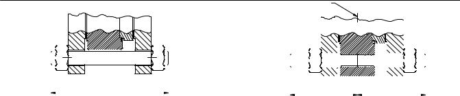
For single flange valve bodies with threaded line bolt holes, personal injury and property damage could result from sudden release of process pressure if line bolts are not properly installed. To ensure proper line bolt thread engagement, line studs must be centered in the threaded section of the valve body so that each stud has equal thread engagement in the body. See figure 2.
8.After centering the valve body, first lubricate and then install the remaining line flange bolting to secure the valve in the pipeline. Tighten the nuts to the line flange studs in a crisscross pattern to ensure proper alignment of valve, gaskets, and flanges.
5
A81 Valve |
Instruction Manual |
May 2011 |
D103302X012 |
|
|
Table 5. Stud Bolt Data
VALVE SIZE |
|
|
WAFER STYLE AND SINGLE FLANGE STYLE WITH THROUGH DRILLED HOLES |
|
|
||||||||
|
PN 10 |
|
|
PN 16 |
|
|
PN 25 |
|
|
PN 40 |
|
||
|
|
|
|
|
|
|
|
|
|||||
|
No. of |
Size Dia |
A |
No. of |
Size Dia |
A |
No. of |
Size Dia |
A |
No. of |
Size Dia |
A |
|
|
& |
Dimen |
& |
Dimen |
& |
Dimen |
& |
Dimen |
|||||
DN |
Stud |
Stud |
Stud |
Stud |
|||||||||
Thread, |
sion, |
Thread, |
sion, |
Thread, |
sion, |
Thread, |
sion, |
||||||
|
Bolts |
Bolts |
Bolts |
Bolts |
|||||||||
|
mm |
mm |
mm |
mm |
mm |
mm |
mm |
mm |
|||||
|
|
|
|
|
|||||||||
50 |
4 |
M16X2 |
125 |
4 |
M16X2 |
125 |
4 |
M16X2 |
130 |
4 |
M16X2 |
130 |
|
|
|
|
|
|
|
|
|
|
|
|
|
|
|
80 |
8 |
M16X2 |
140 |
8 |
M16X2 |
140 |
8 |
M16X2 |
150 |
8 |
M16X2 |
150 |
|
|
|
|
|
|
|
|
|
|
|
|
|
|
|
100 |
8 |
M16X2 |
150 |
8 |
M16X2 |
150 |
8 |
M20X2.5 |
160 |
8 |
M20X2.5 |
160 |
|
|
|
|
|
|
|
|
|
|
|
|
|
|
|
150 |
8 |
M20X2.5 |
160 |
8 |
M20X2.5 |
160 |
8 |
M24X3 |
180 |
8 |
M24X3 |
180 |
|
|
|
|
|
|
|
|
|
|
|
|
|
|
|
200 |
8 |
M20X2.5 |
170 |
12 |
M20X2.5 |
170 |
12 |
M24X3 |
190 |
12 |
M27X3 |
210 |
|
|
|
|
|
|
|
|
|
|
|
|
|
|
|
250 |
12 |
M20X2.5 |
180 |
12 |
M24X3 |
190 |
12 |
M27X3 |
210 |
12 |
M30X3.5 |
230 |
|
|
|
|
|
|
|
|
|
|
|
|
|
|
|
300 |
12 |
M20X2.5 |
190 |
12 |
M24X3 |
200 |
16 |
M27X3 |
230 |
16 |
M30X3.5 |
250 |
|
|
|
|
|
|
|
|
|
|
|
|
|
|
|
VALVE SIZE |
|
|
|
|
SINGLE FLANGE STYLE (THREADED HOLES) |
|
|
|
|
||||
|
PN 10 |
|
|
PN 16 |
|
|
PN 25 |
|
|
PN 40 |
|
||
|
|
|
|
|
|
|
|
|
|||||
|
No. of |
Size Dia |
B |
No. of |
Size Dia |
B |
No. of |
Size Dia |
B |
No. of |
Size Dia |
B |
|
|
& |
Dimen |
& |
Dimen |
& |
Dimen |
& |
Dimen |
|||||
DN |
Stud |
Stud |
Stud |
Stud |
|||||||||
Thread, |
sion, |
Thread, |
sion, |
Thread, |
sion, |
Thread, |
sion, |
||||||
|
Bolts |
Bolts |
Bolts |
Bolts |
|||||||||
|
mm |
mm |
mm |
mm |
mm |
mm |
mm |
mm |
|||||
|
|
|
|
|
|||||||||
50 |
- - - |
- - - |
- - - |
- - - |
- - - |
- - - |
- - - |
- - - |
- - - |
- - - |
- - - |
- - - |
|
|
|
|
|
|
|
|
|
|
|
|
|
|
|
80 |
16 |
M16X2 |
85 |
16 |
M16X2 |
85 |
16 |
M16X2 |
90 |
16 |
M16X2 |
90 |
|
|
|
|
|
|
|
|
|
|
|
|
|
|
|
100 |
16 |
M16X2 |
90 |
16 |
M16X2 |
90 |
16 |
M20X2.5 |
100 |
16 |
M20X2.5 |
100 |
|
|
|
|
|
|
|
|
|
|
|
|
|
|
|
150 |
16 |
M20X2.5 |
110 |
16 |
M20X2.5 |
110 |
- - - |
- - - |
- - - |
- - - |
- - - |
- - - |
|
|
|
|
|
|
|
|
|
|
|
|
|
|
|
200 |
16 |
M20X2.5 |
110 |
24 |
M20X2.5 |
110 |
24 |
M24X3 |
120 |
- - - |
- - - |
- - - |
|
|
|
|
|
|
|
|
|
|
|
|
|
|
|
250 |
24 |
M20X2.5 |
120 |
24 |
M24X3 |
120 |
24 |
M27X3 |
130 |
- - - |
- - - |
- - - |
|
|
|
|
|
|
|
|
|
|
|
|
|
|
|
300 |
24 |
M20X2.5 |
120 |
24 |
M24X3 |
130 |
24 |
M27X3 |
140 |
24 |
M30X3.5 |
150 |
|
|
WAFER STYLE AND SINGLE FLANGE STYLE WITH THROUGH |
|
SINGLE FLANGE STYLE (THREADED HOLES) |
|
|||||||||
VALVE SIZE |
|
|
DRILLED HOLES |
|
|
|
|
||||||
|
|
|
|
|
|
|
|
|
|
||||
|
|
CL150 |
|
|
CL300 |
|
|
CL150 |
|
|
CL300 |
|
|
|
No. of |
Size Dia |
A |
No. of |
Size Dia |
A |
No. of |
Size Dia |
B |
No. of |
Size Dia |
B |
|
|
& |
Dimen |
& |
Dimen |
& |
Dimen |
& |
Dimen |
|||||
NPS |
Stud |
Stud |
Stud |
Stud |
|||||||||
Thread, |
sion, |
Thread, |
sion, |
Thread, |
sion, |
Thread, |
sion, |
||||||
|
Bolts |
Bolts |
Bolts |
Bolts |
|||||||||
|
Inch |
Inch |
Inch |
Inch |
Inch |
Inch |
Inch |
Inch |
|||||
|
|
|
|
|
|||||||||
2 |
4 |
5/8 11 |
5 |
8 |
5/8 11 |
5.25 |
- - - |
- - - |
- - - |
- - - |
- - - |
- - - |
|
|
|
|
|
|
|
|
|
|
|
|
|
|
|
3 |
4 |
5/8 11 |
5.75 |
8 |
3/4 10 |
6.5 |
8 |
5/8 11 |
4.00 |
16 |
3/4 10 |
4.25 |
|
|
|
|
|
|
|
|
|
|
|
|
|
|
|
4 |
8 |
5/8 11 |
6 |
8 |
3/4 10 |
7 |
16 |
5/8 11 |
4.00 |
16 |
3/4 10 |
4.50 |
|
|
|
|
|
|
|
|
|
|
|
|
|
|
|
6 |
8 |
3/4 10 |
6.5 |
12 |
3/4 10 |
7.5 |
16 |
3/4 10 |
4.25 |
24 |
3/4 10 |
4.75 |
|
|
|
|
|
|
|
|
|
|
|
|
|
|
|
8 |
8 |
3/4 10 |
7 |
12 |
7/8 9 |
9 |
16 |
3/4 10 |
4.50 |
24 |
7/8 9 |
5.50 |
|
|
|
|
|
|
|
|
|
|
|
|
|
|
|
10 |
12 |
7/8 9 |
8 |
16 |
1 8 |
10 |
24 |
7/8 9 |
5.00 |
32 |
1 8 |
6.50 |
|
|
|
|
|
|
|
|
|
|
|
|
|
|
|
12 |
12 |
7/8 9 |
8.5 |
16 |
1 1/8 8 |
11 |
24 |
7/8 9 |
5.25 |
32 |
1 1/8 8 |
7.00 |
|
|
|
|
|
|
|
|
|
|
|
|
|
|
|
Figure 2. Stud Bolts for Installation (also see table 5)
CENTERLINE OF THREADED SECTION
|
|
|
|
|
|
|
|
|
|
|
|
|
|
|
|
|
|
|
|
|
|
|
|
|
|
|
|
|
|
|
|
|
|
|
|
|
|
|
|
|
|
|
|
|
|
|
|
|
|
|
|
|
|
|
|
|
|
|
|
|
|
|
|
|
|
|
|
|
|
|
|
|
|
|
|
|
|
|
|
|
|
|
|
|
|
|
|
|
|
|
|
|
|
|
|
|
|
|
|
|
|
|
|
|
|
|
|
|
|
|
|
|
|
|
|
|
|
|
|
|
|
|
|
|
|
|
|
|
|
|
|
|
|
|
|
|
|
|
|
|
|
|
|
|
|
|
|
|
|
|
|
|
|
|
|
|
|
|
|
|
|
|
|
|
|
|
|
|
|
|
|
|
|
|
|
|
|
|
|
|
|
|
|
|
|
|
|
|
|
|
|
|
|
|
|
|
|
|
|
|
|
|
|
|
|
|
|
|
|
|
|
|
|
|
|
|
|
|
|
|
|
|
|
|
|
|
|
|
|
|
|
|
|
|
|
|
|
|
|
|
|
|
|
|
|
|
|
|
|
|
|
|
|
|
|
|
|
|
|
|
|
|
|
|
|
|
|
|
|
|
|
|
|
|
|
|
|
|
|
|
|
|
|
|
|
|
|
|
|
|
|
|
|
|
|
|
|
|
|
|
|
|
|
|
|
|
|
|
|
|
|
|
|
|
|
|
|
|
|
|
|
|
|
|
|
|
|
|
|
|
|
|
|
|
|
|
|
|
|
|
|
|
|
|
|
|
|
|
|
|
|
|
|
|
|
|
|
|
|
|
|
|
|
|
|
|
|
|
|
|
|
|
|
|
|
|
|
|
|
|
|
|
|
|
|
|
|
|
|
|
|
|
|
|
|
|
|
|
|
|
|
|
|
|
|
|
|
|
|
|
|
|
|
|
|
|
|
|
|
|
|
|
|
|
|
|
|
|
|
|
|
|
|
|
|
|
|
|
|
|
|
|
|
|
|
|
|
|
|
|
|
A |
|
|
|
|
|
|
|
|
|
|
|
|
|
|
|
|
|
|
|
|
|
|
|
|
|
|
|
|
|
|
|
|
|
|
|
|
|
|
|
|
|
|
|
|
|
|
|
|
|
|
|
|
|
|
|
|
|
|
|
|
|
|
|
A3887-1 |
|
|
|
|
|
|
|
|
|
|
|
|
|
|
|
|
|
|
|
|
|
|
|
|
|
|
|
|
|
|
|
|
|
|
|
A3886-1 |
|
|
|
|
|
|
|
|
|
|
|
|
B |
|
|
|
|
|
|
|
|
|
|
|
|
|
|
|
|
|
B |
|
|
|
|
|
|
|
|
|
|
|
|
|
|||||
|
|
|
|
|
|
|
|
|
|
|
|
|
|
|
|
|
|
|
|
|
|
|
|
|
|
|
|
|
|
|
|
|
|
|
|
|
|
|
|
|
|
|
|
|
|
|
|
|
|
|
|
|
|
|
|
|
|
|
|
|
|
|
|
|
|
|
|
|
|
|
|
|
|
|
|
|
|||||||||
|
|
|
|
|
|
|
|
|
|
|
|
|
|
|
|
|
|
|
|
|
|
|
|
|
|
|
|
|
|
|
|
|
|
|
|
|
|
|
|
|
|
|
|
|
|
|
|
|
|
|
|
|
|
|
|
|
|
|
|
|
|
|
|
|
|
|
|
|
|
|
|
|
|||||||||||||
|
|
|
|
|
|
|
|
|
|
|
|
|
|
|
|
|
|
|
|
|
|
|
|
|
|
|
|
|
|
|
|
|
|
|
|
|
|
|
|
|
|
|
|
||||||||||||||||||||||||||||||||||||||||||
|
|
|
|
|
|
|
|
|
|
|
|
|
|
|
|
|
|
|
|
|
|
|
|
|
|
|
|
|
|
|
|
|
|
|
|
|
|
|
|
|
|
|
|
|
|
|
|
|
|
|
|
|
|
|
|
|
|
|
|
|
|
|
|
|
|
|
|
|
|
|
|
||||||||||||||
|
|
|
|
|
WAFER STYLE VALVE BODY |
|
SINGLE FLANGE STYLE VALVE BODY (THREADED HOLES) |
||||||||||||||||||||||||||||||||||||||||||||||||||||||||||||||||||||||||||||||
6

Instruction Manual |
A81 Valve |
D103302X012 |
May 2011 |
|
|

 WARNING
An A81 valve body is not necessarily grounded when installed in a pipeline. If the valve is used in a flammable or hazardous atmosphere or for oxygen service, an explosion could result due to a discharge of static electricity from the valve components. To avoid personal injury or property damage, always make sure the valve body is grounded to the pipeline before putting the control valve assembly into operation in a flammable or hazardous atmosphere.
Note
Standard packings for the A81 valve are composed of all conductive packing rings (graphite ribbon packing) or partially conductive packing rings (such as a carbon filled PTFE female adaptor with PTFE V ring packing) to electrically bond the shaft to the valve body for hazardous area service. For oxygen service applications, provide alternate shaft to valve body bonding according to the following step.
9.For oxygen service applications, attach the bonding strap assembly (key 131, figure 3) to the shaft with the clamp (key 130, figure 3), and connect the other end of the bonding strap assembly to the valve body with the cap screw (key 35). Secure each cap screw with a hex nut (key 36).

 WARNING
Personal injury could result from packing leakage. Valve packing was tightened prior to shipment; however, the packing might require some readjustment to meet specific service conditions.
Figure 3. Optional Shaft to Valve Body Bonding Strap Assembly
7

A81 Valve |
Instruction Manual |
May 2011 |
D103302X012 |
|
|
Figure 4. Packing Arrangement Details
GE39901 A |
PTFE V RING |
GE39986 A |
GRAPHITE RIBBON |
STANDARD PACKING
|
|
GE40113 A |
SINGLE PTFE PACKING |
GE40118 A |
GRAPHITE PACKING |
|
|
|
|
||
|
|
|
|
ENVIRO SEAL PACKING |
|
|
|
NOTES: |
|
|
|
|
1 |
WITH CONDUCTIVE PACKING, THE FEMALE ADAPTOR IN PTFE V RING PACKING IS CARBON FILLED PTFE. |
|
||
|
2 |
APPLY LUBRICANT. |
|
|
|
|
|
|
|||
3 |
THESE TWO SURFACES SHOULD REMAIN PARALLEL AS YOU ALTERNATELY AND EVENLY TIGHTEN THE PACKING NUTS (KEY 28). |
||||
|
|
|
|
|
|
Valves with ENVIRO SEALt packing systems will not require this initial re adjustment. See ENVIRO SEAL Packing System for Rotary Valves Instruction Manual (D101643X012) for packing instructions. If you wish to convert your present packing arrangement to ENVIRO SEAL packing, refer to the retrofit kits listed in the parts kit sub section on page 19 of this manual.
Maintenance
Valve body parts are subject to normal wear and must be inspected regularly and replaced as necessary. The frequency of inspection and replacement depends upon the severity of service conditions. Instructions are given in this section for: replacing trim components, changing disk rotation or valve action, and mounting and adjusting the actuator.
As used in these instructions, actuator refers to power actuators (such as pneumatic diaphragm, piston actuators, and rack and pinion actuators).
8
 Loading...