


Therm-O-Disc
Product Information
INNOVATIVE SOLUTIONS
Sensing Solutions
Putting systems in touch with their surroundings to enable new levels of understanding, awareness, and response.
Electro- |
Packaged |
Wireless |
Mechanical |
Sensors |
|
Bimetals |
Temperature |
WiHART |
Thermal |
Gasoline |
Power |
Fuses |
Vapors |
|
(TCO) |
|
|
Hermetic Solutions
Ensuring a robust electrical or signal connection across adverse environmental conditions.
|
Engineered |
|
Products |
|
AC/R |
|
|
|
Defense |
Industrial |
|
|||
Terminals |
Sensor/Power |
|
Packages |
|
SH Plates |
Feedthroughs |
|
Feedthroughs |
|
Power Bolts |
Battery Seals |
|
Initiator |
|
Sight Glass |
|
|
|
Assemblies |
|
|
|
|
Laser Lidding |
|
|
|
|
|
Enabling safe, reliable, and efficient system control.
Trustworthy, stable |
|
Broadest range of |
company with over 75 |
|
|
|
product options |
|
|
||
years of proven reliability |
|
|
|
|
|
Over 1/2 billion units |
|
Local, direct support, |
produced annually |
|
|
|
worldwide |
|
|
|
Leading product |
Rapid custom |
application experts |
prototypes |

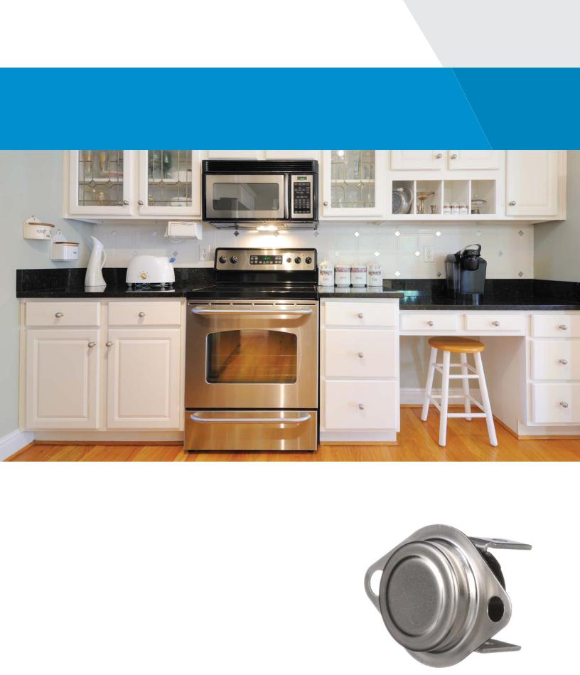
Bimetal Disc
Thermostat
Product Information and
Application Notes

|
Table of Contents |
Application Notes |
...........................................................................................................................................3 |
10H /10HMR ................................................................................................................................................ |
12 |
10RS............................................................................................................................................................. |
16 |
12S, 14S, 15S ............................................................................................................................................... |
19 |
14T............................................................................................................................................................... |
26 |
30M.............................................................................................................................................................. |
33 |
36T /36TMR/36F .......................................................................................................................................... |
38 |
37T............................................................................................................................................................... |
52 |
39T............................................................................................................................................................... |
61 |
44T, 48T ....................................................................................................................................................... |
65 |
49T, 49F ....................................................................................................................................................... |
70 |
58T............................................................................................................................................................... |
74 |
59T, 66T ....................................................................................................................................................... |
79 |
60T/60TMR .................................................................................................................................................. |
85 |
60F, 61F........................................................................................................................................................ |
95 |
64T,64F ........................................................................................................................................................ |
98 |
69T............................................................................................................................................................ |
102 |
74T............................................................................................................................................................ |
108 |
75TF.......................................................................................................................................................... |
112 |
HLX ........................................................................................................................................................... |
117 |
Bimetal Disc Thermostat
Application Notes
Operating Principles
Bimetal disc thermostats are thermally actuated switches.
When the bimetal disc is exposed to its predetermined calibration temperature, it snaps and either opens or closes a set of contacts. This breaks or completes the electrical circuit that has been applied to the thermostat.
Bimetal Disc Thermostat |
3 |
Therm-O-Disc |
There are three basic types of thermostat switch actions:
•Automatic Reset: This type of control can be built to either open or close its electrical contacts as the temperature increases. Once the temperature of the bimetal disc has returned to the specified reset temperature, the contacts will automatically return to their original state.
•Manual Reset: This type of control is available only with electrical contacts that open as the temperature increases. The contacts may be reset by manually pushing on the reset button after the control has cooled below the open temperature calibration.
•Single Operation: This type of control is available only with electrical contacts that open as the temperature increases. Once the electrical contacts have opened, they will not automatically reclose unless the ambient that the disc senses drops to a temperature well below room temperature (typically below -31°F).
Temperature Sensing & Response
Many factors can affect how a thermostat senses and responds to temperature changes in an application. Typical factors include, but are not limited to, the following:
•Mass of the thermostat
•Switch head ambient temperature. The “switch head” is the plastic or ceramic body and terminal area of the thermostat. It does not include the sensing area
•Air flow across the sensing surface or sensing area.
The “sensing surface” (or area) consists of the bimetal disc and metal disc housing
•Air flow across the switch head of the thermostat
•Internal heating from carrying the application electrical load
•Disc cup or housing type (i.e. enclosed, as on left in picture below, or exposed, as on right)
•Rate of temperature rise and fall in the application
•Intimacy of contact between the thermostat sensing surface and the surface it is mounted on
•Heat transfer by conduction, convection or radiation
Therm-O-Disc |
4 |
Bimetal Disc Thermostat |
It is important to understand that the temperature of the thermostat will typically change more slowly than or lag the temperature it is trying to sense. The impact of the factors mentioned previously will determine the magnitude of the thermal lag. Thermal lag will directly affect determination of thermostat calibration to regulate or limit temperature for a particular application. Reference the “Determining Calibration” section for how to use a thermocouple sample thermostat to establish thermostat calibration.
Control Location
The location of the thermostat should be carefully selected. Adequate time should be used to determine the temperatures in the various locations within the product to assure the location of the sensor can best measure and control the performance of the product. Various methods may be employed to measure these temperatures such as infrared thermography, multiple thermocouples, etc.
Determining Calibration
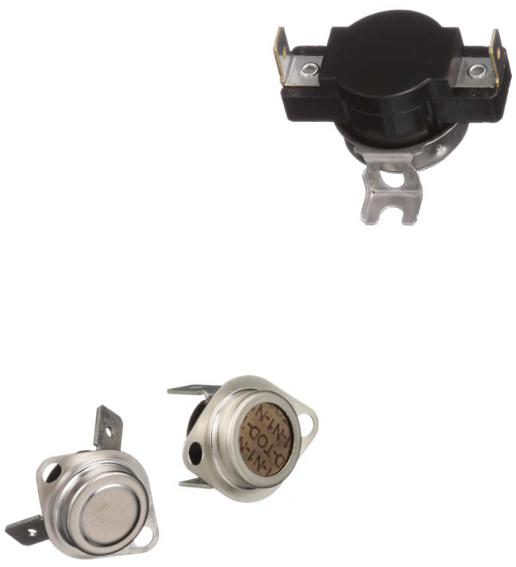
A thermocouple sample thermostat is typically used as a key indication of what the calibration temperature of a thermostat should be for a particular application (see Figure 3). The thermocouple is ideally attached internally to the control on the bimetal disc for optimum results since the bimetal disc is the component that senses the temperature in a bimetal thermostat. The sample control has the same thermal response as a functional thermostat but the
contacts will not open.
Once a preliminary calibration temperature has been determined with the thermocouple sample control, a functional control calibrated at the desired temperature must be tested in the application to verify that the calibration is appropriate. Therm-O-Disc provides thermocouple samples upon request. Type J, Type K, and Type T thermocouples are available.
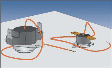
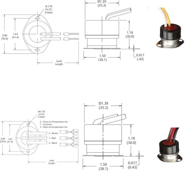
A thermocouple may be placed externally on a thermostat (see Figures 4 and 5). The preferable location would be on the metal disc “cup” / mounting bracket at a point closest to the sensing surface. The sensing surface is the flat area of the “cup” or bimetal housing for thermostats with enclosed bimetal discs. Those with
exposed bimetal discs should have the thermocouple positioned as close to the disc as is practical. Care should be taken to assure that the thermocouple wires do not contact one another except at the sensing junction.
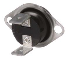
Figure 3
Thermocouple Sample Controls
Bimetal Disc Thermostat |
5 |
Therm-O-Disc |
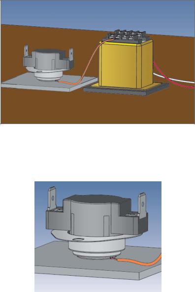
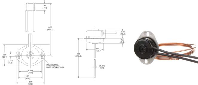
Figure 4
Thermocouple placed externally to thermostat
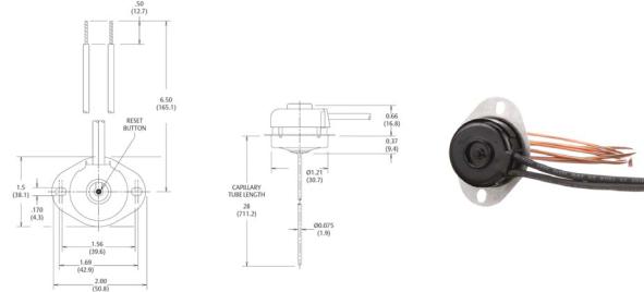
Figure 5
Thermocouple placed externally to thermostat
Therm-O-Disc |
6 |
Bimetal Disc Thermostat |

Thermostats are used to both regulate and to limit temperatures.
A thermostat that regulates temperature is exposed to temperatures of normal operating conditions of a particular application, plus an
overshoot temperature. A thermostat that limits temperature is exposed to temperatures of abnormal operating conditions, plus an overshoot temperature. It is important to determine both the normal and abnormal operating temperatures as well as the respective temperature overshoots in each application in order to specify the appropriate thermostat calibration. Since most applications include both regulating and limiting thermostats, it is essential to prevent nuisance tripping of the limit by fully understanding the temperature overshoots. It is important to know what the maximum exposure temperature is to assure that components and complete units do not exceed their respective rated temperatures.
The maximum exposure temperature is the combined result of the maximum ambient temperature added to the temperature increase due to the application plus the overshoot.
Test Guidelines
Install the thermocouple sample thermostat in the appropriate location (see earlier section named “Control Location”) using both the same mounting and electrical connections as will be used in the application. The thermocouple lead should be connected to a device that will monitor and record the output from the thermocouple. Only personnel properly trained in the safe use of electrical equipment should perform testing. Caution must be exercised to assure that line voltage, if present, must not injure personnel or damage equipment. Use of an isolation transformer is recommended if there is any chance that the thermocouple wires may see line voltage.
CAUTION To avoid a false reading of the unit under test, thermocouple wires must not make contact with each other except at the temperature sensing junction.
CAUTION Ensure that the thermocouple wire insulation will provide isolation against short circuiting and shock hazards.
CAUTION The terminal of the temperature measuring instrument, to which the thermocouple is attached, will be the same potential as the connecting circuit wire. This instrument must be
electrically isolated and considerable caution must be exercised in its use, since one of the thermocouple terminals is frequently grounded to the instrument chassis.
It will likely be necessary to conduct several trials with varying ambient temperature, air flow rate and/or volume, rate of temperature rise or fall, etc. to identify normal and abnormal operation. Normal manufacturing and assembly variation between units and any applicable approval agency requirements or industry standards must also be considered.
Bimetal Disc Thermostat |
7 |
Therm-O-Disc |
Monitor the temperatures under normal operating conditions using the thermocouple sample thermostat. Repeat using conditions for abnormal operating conditions. Conduct as many trials as are necessary to understand all the potential fault conditions and to assure that the rated temperature of components (including the thermostat) and the test units are not exceeded. The test may be set up to be able to manually open the electrical circuit when the thermocouple sample thermostat reaches a particular target temperature (as determined from testing described above). Continuing to monitor the temperature of the thermocouple sample after the circuit is manually opened, and determining the maximum temperature excursion beyond the “open” temperature can determine the temperature overshoot.
This can be conducted for both regulating and limiting thermostats. Once the preliminary calibration value for the thermostat has been determined, by taking into account normal and abnormal operating conditions, product and test variation and overshoots, it is necessary to repeat testing with functional thermostats. It may be necessary to try thermostats calibrated both higher and lower than the targeted temperature to better optimize the calibration temperature. This will also provide useful information for specifying the calibration tolerance.
Important Notice
Users must determine the suitability of the control for their application, including the level of reliability required, and are solely responsible for the function of the end-use product. These controls contain exposed electrical components and are not intended to withstand exposure to water or other environmental contaminants which can compromise insulating components. Such exposure may result in insulation breakdown and accompanying localized
electrical heating.
A control may remain permanently closed or open as a result of exposure to excessive mechanical, electrical, thermal or environmental conditions or at normal end-of-life. If failure of the control to operate could result in personal injury or property damage, the user should incorporate supplemental system control features to achieve the desired level of reliability and safety. For example, backup controls have been incorporated in a number of applications for
this reason.
Therm-O-Disc |
8 |
Bimetal Disc Thermostat |
Glossary
Ambient – The typical environmental temperature at which a product is exposed.
Approval Agencies – Agencies created to verify the safety and/or functionality of electrical and gas household products. Therm-O-Disc products are typically recognized at the major global agencies, including UL, CSA, VDE, CQC, and MITI.
Automatic Reset – A type of thermostat that will reset itself at a specific temperature (set point minus differential = reset temperature).
Bimetal – Metallic strip material made by bonding two different materials together with different thermal expansion rates.
Bumper – An actuating pin that transmits motion from the sensing mechanism to an actuating arm.
Contacts – Term for components used in all electrical-type products that physically make and break electrical circuits.
Comparative Tracking Index (CTI) – A measure of material surface electrical tracking (resistance).
Cycle Rating – The agency-recognized number of operations that a control will function, given a specific temperature range and electrical load.
Dielectric Strength – A product’s ability to withstand an application of a pre-determined over-voltage for a specified period of time.
Differential – The temperature difference between the opening and closing points of a control.
Disc Cup – A cup that holds a disc in place on a disc-type control.
Disc – A thin, circular bimetallic component.
DPDT (Double Pole, Double Throw) – An electrical term where “pole” is a leg of an electrical circuit and “throw” describes the switch action. Therefore, a DPDT will switch two legs and each leg will open a set of contacts, and close another set (4 contacts).
DPST (Double Pole, Single Throw) – An electrical term where “pole” means a leg of an electrical circuit and “throw” describes the switch action. Therefore, DPST will switch two legs and each leg is switched open or closed by one mechanism.
Fan-Type Control – A thermal control designed such that the contacts close on temperature rise. Also referred to as “close on rise,” or “normally open.”
Fuse-Type Control – A control built to cycle only once.
Limit-Type Control – A thermal control designed such that the contacts open on temperature rise. Also referred to as “open on rise,” or “normally closed.”
M1 – Refers to manual reset devices. If the reset button is held down, the control can cycle thermally.
M2 – Refers to manual reset devices. If the reset button is held down, the control must stay open and not reset automatically.
Bimetal Disc Thermostat |
9 |
Therm-O-Disc |
Manual Reset (M.R.) – A control that opens automatically, but must be reclosed manually by pressing a button or lever.
NTC (Negative Temperature Coefficient) – A resistor that reduces resistance (ohms) with a temperature increase.
Pole – The number of completely separate circuits contained in a control.
Prime Differential – The thermal differential between the nominal open temperature and the minimum close temperature.
PTC (Positive Temperature Coefficient) – A resistor that increases resistance (ohms) with temperature increase.
Reference Dimension – A dimension without tolerance used only for information purposes that does not govern production or inspection operations.
Reset Temperature – The temperature at which the contacts return to their normal position.
Set Point – Temperature at which normally closed contacts will open, or normally open contacts will close. Also referred to as operating temperature.
SPDT (Single Pole, Double Throw) – An electrical switch term where “pole” means a leg of an electrical circuit and “throw” describes the switch action. Therefore, a SPDT will switch one leg that will open a set of contacts, and close another set.
SPST (Single Pole, Single Throw) – An electrical term describing switch actions. A SPST will switch one leg and open one set of contacts.
Stenciling – The marking on a product identifying the product type, calibration temperature, part number and plant of manufacture.
Switchcase – The component that represents the thermostat “body,” made from insulating material that supports switch mechanisms.
Thermal Cutoff (TCO) – A product that functions as a thermal fuse (one time operation). Various operating temperatures are achieved by formulating a pellet that melts at very specific temperatures.
Thermistor – A device that exhibits a large change in electrical resistance with a change in temperature.
Tolerance – The allowable range above or below the set point or reset temperature.
Trip-Free – A term associated with manual reset type controls. When the reset button is depressed it cannot restrict the normal opening of the control.
Therm-O-Disc |
10 |
Bimetal Disc Thermostat |
Important Information
Many variables can affect the operational characteristics of a thermostat. It is for this reason that we recommend that you conduct thorough testing of our products in your specific application. Therm-O-Disc has both functional and thermocoupled samples readily available for determining the desired performance and the correct response in your application. To obtain samples please contact your local Therm-O-Disc sales representative directly. To ensure a quick turnaround, please have the following information ready:
•Application description
•Electrical load
•Operating temperature requirements
•Agency recognition(s) required
•Mounting and terminal configurations
•Estimated annual volume
Don’t know what product you need? Do you have a general question about our products? Visit thermodisc.com or contact your local Therm-O-Disc sales office. Our Applications Engineers are always available to assist you in answering your questions or in obtaining any samples you may need.
Bimetal Disc Thermostat |
11 |
Therm-O-Disc |

10H Linear Limit Series
Special Purpose Controls
Snap-Action Capillary Controls
The 10H series temperature control from Therm-O-Disc was originally developed to sense hot spots along the length of electric baseboard heaters. It is also used in other applications where it is necessary to sense temperatures along a continuous length.
The 10H capillary tube is vacuum-charged with selected fluids to give specific calibrations. When the calibration temperature is reached, a change in fluid vapor pressure allows the diaphragm to snap through and operate the contacts. The snap-action design provides high-speed contact separation and excellent reliability.
Typical applications for the 10H include electric baseboard heaters and other HVAC applications.
Therm-O-Disc |
12 |
Bimetal Disc Thermostat |
Features and Benefits
The 10H features include:
•The ability to sense temperature along a continuous length.
•Excellent sensitivity. Since the capillary tube is charged, the 10H responds to the hottest spot along the capillary tube.
•High-speed contact separation for long contact life.
•Design flexibility provided by a variety of switch actions, capillary tube lengths, mounting brackets and terminations.
Switch Actions
The 10H is available in two switch actions:
Automatic Reset (Type 10H11) – SPST contacts open on temperature rise and automatically reset on temperature fall (see figure 1).
Shown with terminal cover and “push on” mounting bracket.
Figure 1
Dimensions are shown in inches and (millimeters).
Manual Reset (Type 10H14) – SPST contacts open on temperature rise and can be reset when the control has cooled to a lower temperature and the reset button has been depressed. The 10H manual reset is agency recognized as an “M1 trip free” construction, which means that if the reset button is held down, the control can cycle thermally
(see figure 2).
Bimetal Disc Thermostat |
13 |
Therm-O-Disc |
Shown with required terminal cover and standard mounting bracket
Figure 2
Dimensions are shown in inches and (millimeters).
Terminal Characteristics
The 10H can be calibrated to open on temperature rise between 150°F (65.6°C) and 350°F (177°C), with a standard tolerance of ±15°F (±8.5°C). The 10H automatic reset will reclose the contacts at approximately 40°F (22°C) below its open temperature. Manual reset controls may automatically reset when exposed to temperatures below -31°F (-35°C).
Capillary Tube
The 10H is available with the copper capillary tube in preferred lengths from 24” to 144” as measured from the bottom of the mounting flange.
Mounting Brackets
The standard mounting bracket (see figure 2) has two slots, each .170” (4.318mm) wide. An alternate “push on” mounting bracket (see figure 1) is also available.
Terminations
Standard leads are two 6 1/2” (165.1mm), #14 AWG, 105°C, 1/32” (10.8mm) thick, black PVC insulation, stripped 1/2” (12.7mm). Also available (automatic reset only) are 1/4”(6.30mm), 90° angle, .032” (0.8mm) blade terminals. A snap-on terminal cover is available for controls supplied with lead wires.
Therm-O-Disc |
14 |
Bimetal Disc Thermostat |

General Electrical Ratings
The 10H series of controls has been rated UL and CSA. The agency ratings can be used as a guide when evaluating specific applications. However, the mechanical, electrical, thermal and environmental conditions to which a control may be exposed in an application may differ significantly from agency test conditions. Therefore, the user must not rely solely on agency ratings, but must perform adequate testing of the product to confirm that the control
selected will operate as intended in the user’s application.
Thermostat |
Maximum Open |
Maximum |
Volts |
Resistive |
Inductive Amps |
Pilot |
|
Agency |
||
Switchcase |
|
|
Cycles |
|||||||
Type |
Temperature |
AC |
Amperes |
FLA |
LRA |
Duty VA |
Recognition |
|||
Temperature |
|
|||||||||
|
|
|
|
|
|
|
|
|
||
10H11 |
350 °F (177 °C) |
221 °F (100 °C) |
277 |
25 |
4.8 |
28.8 |
480 |
100,000 |
|
|
(Auto Reset) |
600 |
- |
- |
- |
125 |
100,000 |
UL |
|||
|
|
|||||||||
10H14 |
|
|
|
|
|
|
|
|
Guide MBPR2, |
|
|
|
277 |
25 |
4.8 |
28.8 |
480 |
6,000 |
File MH-5304 |
||
(Manual |
350 °F (177 °C) |
221 °F (100 °C) |
||||||||
600 |
- |
- |
- |
125 |
6,000 |
|
||||
Reset) |
|
|
|
|||||||
|
|
|
|
|
|
|
|
|
||
10H11 |
350 °F (177 °C) |
221 °F (100 °C) |
277 |
25 |
- |
- |
125 |
100,000 |
|
|
|
||||||||||
(Auto Reset) |
600 |
10 |
- |
- |
- |
100,000 |
|
|||
|
|
CSA File |
||||||||
10H14 |
|
|
277 |
25 |
|
|
460 |
6,000 |
||
|
|
|
|
LR19988 |
||||||
(Manual |
350 °F (177 °C) |
221 °F (100 °C) |
350 |
15 |
|
|
350 |
6,000 |
|
|
Reset) |
|
|
600 |
10 |
|
|
400 |
6,000 |
|
|
Note: For complete and current ratings, please consult a Therm-O-Disc sales engineer. At thermostat end-of-life, the contacts may remain permanently open or closed.
Bimetal Disc Thermostat |
15 |
Therm-O-Disc |

10RS Radiant Energy Series
Special Purpose Control
Snap-Action Radiant Controls
The 10RS line of controls from Therm-O-Disc offers reliable sensing of radiant energy in hot surface ignition applications, such as gas clothes dryers.
The unique snap-action bimetal design not only provides high-speed contact separation and time-proven reliability, but also enables the 10RS to maintain radiant sensitivity while compensating for ambient temperature changes.
A glass ‘window’ is used to maximize the effect of radiant energy on the bimetal element without exposing the entire control to high ignitor temperatures.
These features have made the Therm-O-Disc 10RS an integral component of gas ignition systems.
Therm-O-Disc |
16 |
Bimetal Disc Thermostat |

Features and Benefits
The 10RS features include:
•Glass “window” design maximizes effect of radiant energy without sensor overheating.
•Unique “U”-shaped actuator compensates for ambient temperature conditions.
•High-speed contact switching for exceptional life characteristics.
Switch Actions and Typical Applications
The 10RS is an automatic reset, single pole, single throw (SPST) switch that opens its electrical contacts when exposed to heat generated by radiant energy. This is accomplished with a “U”-shaped bimetal actuator which has one leg exposed to radiant energy while the other leg is shielded.
As radiant energy passing through the glass “window” heats the exposed bimetal leg, a temperature differential is created which causes the bimetal element to snap and open the contacts. As radiant energy dissipates, both actuator legs return to approximately the same temperature, allowing the contacts to automatically reclose.
Typical Applications
The type 10RS control is utilized in gas-fired appliances in conjunction with a hot surface ignitor. As red hot ignitor temperatures are achieved, the 10RS opens the circuit which signals the gas valve to open. Upon ignition, radiant energy from the gas flame keeps the 10RS open until the operating cycle is completed. Once the gas valve closes and the flame dissipates, the contacts reclose and the ignition cycle is complete.
Calibration
The standard 10RS calibration calls for the contacts to open within 12 to 20 seconds after exposure to a radiant energy source. Contact reclose occurs within 26 to 40 seconds after the radiant source dissipates.
Note: Calibration timing of the 10RS in the actual application is dependent upon the type of ignition system and position of the sensor relative to the radiant energy source.
Dimensions are shown in inches and (millimeters).
Bimetal Disc Thermostat |
17 |
Therm-O-Disc |
Mounting Bracket
The 10RS is available in two standard tab mounts. The brackets are fabricated from .032” (.81mm) aluminum and can easily be mounted with a sheet metal screw.
Terminal Configurations
The 10RS is furnished with .032” x .250” (.81mm x 6.35mm) brass quick connects in the horizontal position.
General Electrical Ratings
The agency ratings can be used as a guide when evaluating specific applications. However, the mechanical, electrical, thermal and environmental conditions to which a control may be
exposed in an application may differ significantly from agency test conditions. Therefore, the user must not rely solely on agency ratings, but must perform adequate testing of the product to confirm that the control selected will operate as intended in the user’s application.
Maximum Bimetal |
Maximum Ambient |
Cycles |
Resistive Amperes |
Volts AC |
Agency Recognition |
|
Temperature (°F) |
Temperature (°F) |
|||||
|
|
|
|
|||
375 |
325 |
100,000 |
5.75 |
120 |
CSA |
|
File 112672-0-000 |
||||||
|
|
|
|
|
Note: At thermostat end-of-life the contacts may remain permanently closed or open. For complete and current ratings, please contact our Sales Engineering Department
Therm-O-Disc |
18 |
Bimetal Disc Thermostat |
12S, 14S, 15S Series
Time Delay Relays and Sequencers
Time Delay Relays and Sequencers
The Therm-O-Disc type 12S, 14S and 15S series time delay relays and sequencers are fieldproven devices for controlling the operation of heating elements and/or fans in electric furnaces and heat pumps. These controls combine a solid-state positive temperature coefficient (PTC) heater with bimetal actuated contacts to provide time-delayed electrical switching. A wide variety of bimetal disc and PTC combinations are available to provide a broad range of timings. The 12S is a single timing device while the 14S uses two bimetal discs to achieve two independent timings. The 15S consists of one, two or three 12S and/or 14S controls mounted on a common plate.
Bimetal Disc Thermostat |
19 |
Therm-O-Disc |
Features and Benefits
The 12S, 14S and 15S features include:
•Available with auto-reset SPST, DPST and SPDT switch configurations.
•PTC heater for stable operation over a wide range of temperatures and voltages.
•Snap-action bimetal disc for high-speed contact separation.
•Standard operating ambients between -40°F (-40°C) and 150°F (65.6°C).
•Available with a wide variety of terminals and mounting plates.
•Welded construction for integrity of current-carrying components.
•Quiet operation
Switch Actions and Typical Applications
Automatic Reset SPST – Can be built to either open or close a set of contacts within a specified time range.
Automatic Reset DPST – Utilizes one bimetal disc to simultaneously open or close two independent sets of contacts within a specified time range.
Automatic Reset SPDT – This 12S configuration is the same as the SPST except with the addition of an auxiliary contact that makes and breaks circuit in opposition to the main contacts.
CAUTION . . . When designing a SPDT circuit, an electrical load must be applied to terminal 2 and/or 3 to avoid a transient short circuit condition during switching.
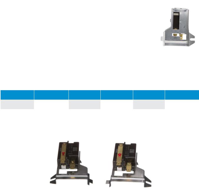
12S Series
The 12S series utilizes one bimetal disc to achieve single-timing operation. The 12S is available in SPST (see figure 1), SPDT (see figure 2), and DPST (see figure 3) switch actions. A variety of standard timings are available for general time delay applications.
SPST Switch Action |
SPDT Switch Action |
(12S20) |
(12S50) |
Figure 1 |
Figure 2 |
Therm-O-Disc |
20 |
Bimetal Disc Thermostat |
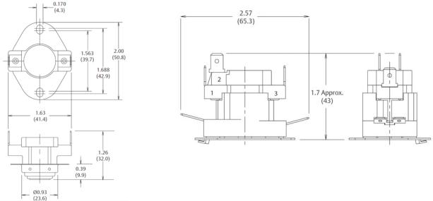
DPST Switch Action
(12S22) Figure 3
Dimensions are shown in inches and (millimeters).
12S Timings*
PTC |
ON |
OFF |
|
|
1-30 Sec. |
40-80 Sec. |
|
24VAC |
10-40 Sec. |
20-60 Sec. |
|
20-55 Sec. |
15-55 Sec. |
||
|
|||
|
25-110 Sec. |
5-45 Sec. |
*Please contact us to discuss specific timings needed.
14S Series
The 14S series is available in two possible configurations:
•2 stages, where each stage is SPST and operated by a disc for each stage. The two stages can have different on/off times. See figure 4.
•3 stages, where the two lower stages are DPST operated simulataneously by one disc. The top stage is SPST and operated by the other disc.
SPST Switch Action (Each Stage)
(14S22) Figure 4
Dimensions are shown in inches and (millimeters).
Bimetal Disc Thermostat |
21 |
Therm-O-Disc |
14S Timings*
PTC |
ON |
OFF |
|
|
|
24VAC |
1-110 Sec. |
1-110 Sec. |
|
|
|
*Please contact us to discuss specific timings needed.
15S Series
The 15S series consists of either two or three 12S and /or 14S controls mounted on a common baseplate. The timing of the package assures that a set of designated contacts will turn on first and turn off last.
The chart shows the timing range for the 15S package.
15S Timings*
PTC |
ON |
OFF |
24V |
1-110 Sec. |
1-110 Sec. |
*Please contact us to discuss specific timings needed. |
|
|
PTC Heater |
|
|
Solid state PTC (Positive Temperature Coefficient) heaters are used to bias the operation of the contacts. These heaters are self-current limiting for stable switch operation over a range of temperatures and over-voltages. The standard line of controls uses a 24VAC PTC rated for Class II circuits. The peak inrush current of the 24VAC PTC heater varies from .35 to 1.0 amps. The inrush current drops below 1/2 of the peak value within approximately 10 seconds and reaches a steady state current between 0.10 and 0.18 amps.
Operating Ambients
The standard sequencer line is designed to operate in ambients ranging from -40°F to 150°F (-40°C to 65.6°F). The actual sequencer ON and OFF times are 100% checked to the required timings at a 75°F (23.9°C) ambient. The OFF timings are determined after the PTC heater has been energized for a total of five minutes. Timings in an ambient above or below 75°F (23.9°C) will vary and should be evaluated in the end use application to determine suitability. A specfic high ambient construction is available at extra cost to allow operation up to 165°F (74°C). This construction requires an “H” in our type number (example 12SH22).
Standard Terminals and Markings
The standard heater terminals are .032” x .250” (6.3 x .8mm) double 15° brass male quick connects. The stage terminals are .032 x .250” (6.3 x .8 mm) tin plated brass. See figures 1, 2, 3, 4 for common stage terminals and terminal numbering
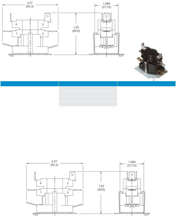
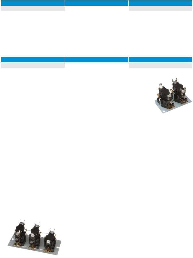
Mounting Plates
The standard mounting plate incorporates a tab and hole arrangement for mounting one (see figure 5) or two (see figure 6) controls. The standard mounting plate for three controls incorporates a slot and hole arrangement (see figure 7). Optional or custom mounting plates are available to meet specific application requirements.
Therm-O-Disc |
22 |
Bimetal Disc Thermostat |

Figure 5 |
Figure 6 |
Figure 7 |
Electrical Spacings
The 12S, 14S, 15S series have electrical spacings of 1/4” (6.35mm) through air and 3/8” (9.52mm) over surface to ground. With the suffix “X,” increased spacings of 3/8” (9.53mm) through air and 1/2” (12.7mm) over surface to ground are available.
General Electrical Ratings
The agency ratings can be used as a guide when evaluating specific applications. However, the mechanical, electrical, thermal and environmental conditions to which a control may be exposed in an application may differ significantly from agency test conditions. Therefore, the user must not rely solely on agency ratings, but must perform adequate testing of the product to confirm that the control selected will operate as intended in the user’s application.
Bimetal Disc Thermostat |
23 |
Therm-O-Disc |

UL Agency Rating
Type |
Switching Action |
Volts AC |
Resistive |
Inductive amps |
Pilot Duty |
Cycles |
Agency Recognition |
||
Amps |
|
|
VA |
||||||
|
|
|
FLA |
LRA |
|
|
|||
|
|
|
|
|
|
|
|||
|
|
240 |
25 |
8 |
48 |
- |
100,000 |
|
|
12S/15S |
SPST |
240 |
30* |
- |
- |
- |
100,000 |
|
|
277 |
25 |
- |
- |
- |
30,000 |
|
|||
|
|
|
|||||||
|
|
480 |
12.5 |
5 |
30 |
480 |
100,000 |
|
|
|
SPDT |
240 |
25 |
8 |
48 |
- |
100,000 |
|
|
12S |
277 |
25 |
- |
- |
- |
30,000 |
|
||
(Main Contacts 1-3) |
|
||||||||
|
480 |
12.5 |
5 |
30 |
480 |
100,000 |
|
||
|
|
|
|||||||
|
|
240 |
- |
4.1 |
8 |
125 |
30,000 |
|
|
12S |
SPDT |
277 |
25 |
- |
- |
- |
30,000 |
|
|
(Auxiliary Contacts 1-2) |
480 |
- |
- |
- |
125 |
30,000 |
UL E19279 |
||
|
|||||||||
|
|
480 |
- |
3 |
16 |
- |
100,000 |
|
|
|
|
120 |
- |
13.8 |
82.8 |
125 |
30,000 |
|
|
|
|
240 |
25 |
8 |
48 |
125 |
100,000 |
|
|
12S/15S |
DPST |
240 |
30* |
- |
- |
- |
30,000 |
|
|
|
|
277 |
25 |
- |
- |
- |
30,000 |
|
|
|
|
480 |
12.5 |
5 |
30 |
480 |
100,000 |
|
|
|
2 Pole and |
240 |
25 |
8 |
- |
- |
100,000 |
|
|
14S |
240 |
30* |
- |
- |
- |
100,000 |
|
||
3 Pole |
|
||||||||
|
480 |
12.5 |
5 |
- |
- |
100,000 |
|
||
|
|
|
|||||||
* Note: For complete ratings information, please contact our Sales Engineering Department. At thermostat end-of-life, the contacts may remain |
|||||||||
permanently closed or open. Maximum combination inductive/resistive, where maximum inductive load is 7FLA, 42LRA. Upper Stage Only.
CSA Agency Ratings
Type |
Switching Action |
Volts AC |
Resistive |
Inductive amps |
Pilot Duty |
Cycles |
Agency Recognition |
||
amps |
|
|
VA |
||||||
|
|
|
FLA |
LRA |
|
|
|||
|
|
|
|
|
|
|
|||
|
|
120 |
- |
1.0 |
6.0 |
- |
100,000 |
|
|
12S/15S |
SPST |
240 |
- |
5.0 |
30 |
- |
100,000 |
|
|
240 |
30* |
- |
- |
- |
100,000 |
|
|||
|
|
|
|||||||
|
|
480 |
- |
- |
- |
125 |
100,000 |
|
|
|
SPDT |
120 |
- |
10 |
60 |
- |
100,000 |
|
|
12S |
240 |
- |
5 |
30 |
- |
100,000 |
|
||
(Main Contacts 1-3) |
|
||||||||
|
480 |
- |
- |
- |
125 |
100,000 |
|
||
|
|
|
|||||||
|
SPDT |
120 |
10 |
- |
- |
125 |
100,000 |
|
|
12S |
240 |
5 |
5 |
30 |
- |
100,000 |
CSA 062037 |
||
(Auxiliary Contacts 1-2) |
|||||||||
|
480 |
- |
- |
- |
125 |
30,000 |
|
||
|
|
|
|||||||
|
|
120 |
- |
10 |
60 |
- |
100,000 |
|
|
12S/15S |
DPST |
240 |
25 |
5 |
30 |
- |
100,000 |
|
|
240 |
30* |
- |
- |
- |
100,000 |
|
|||
|
|
|
|||||||
|
|
480 |
- |
- |
- |
125 |
100,000 |
|
|
|
2 Pole+ |
240 |
25 |
5 |
30 |
- |
100,000 |
|
|
14S |
240 |
30* |
- |
- |
- |
100,000 |
|
||
3 Pole |
|
||||||||
|
480 |
- |
- |
- |
12.5 |
100,000 |
|
||
|
|
|
|||||||
* Note: For complete ratings information, please contact our Sales Engineering Department. At thermostat end-of-life, the contacts may remain permanently closed or open. Maximum combination inductive/resistive, where maximum inductive load is 7FLA, 42LRA. Upper Stage Only.
Therm-O-Disc 24 Bimetal Disc Thermostat

Part Numbering System
Common Sequencer Type Numbers for 12S and 145
Type |
Number of Stages |
Description |
12S20 |
1 |
Normally Open, SPST |
12S22 |
2 |
Normally Open, DPST |
12S50 |
1 |
Normally Open, SPDT |
14S22 |
2 |
Normally Open, Each Stage SPST |
14S222 |
3 |
Normally Open – |
|
|
Lower Two Stages DPST |
|
|
Upper Stage SPST |
15S Type Numbers
1st Suffix |
2nd Suffix |
3rd Suffix |
Base sequencer type |
1st sequencer |
2nd sequencer on |
3rd sequencer on |
|
on baseplate |
baseplate (if provided) |
baseplate (if provided) |
at each location |
1 |
1 |
1 |
12S20 |
2 |
2 |
2 |
12S22 |
4 |
4 |
4 |
14S22 |
You can combine any above configurations on a common base plate.
Example: 15S221 would contain 12S22-12S22-12S20
Bimetal Disc Thermostat |
25 |
Therm-O-Disc |
14T Series
Moisture Resistant Temperature Controls
Heavy-Duty Snap-Action Temperature Controls
The 14T line of heavy-duty sealed bimetal disc controls from Therm-O-Disc meets the higher electrical requirements of commercial applications. The design provides moisture resistance for moisture prone environments. The snap-action of the 1” temperature sensing bimetal disc provides high-speed contact separation resulting in exceptional life characteristics at electrical loads up to 25 amps at 120/240VAC. A variety of mounting configurations, lead wires and terminations
give maximum design flexibility. The heavy-duty construction and long life characteristics have made the 14T a popular choice for heating, ventilation and air conditioning systems.
Therm-O-Disc |
26 |
Bimetal Disc Thermostat |
Features and Benefits
The 14T features include:
•Sealed construction provides moisture resistance for moisture prone environments.
•High-speed contact separation ensures long contact life.
•A wide variety of mounting configurations, lead wires and terminations provide maximum design flexibility.
•Large 25 amp capacity allows direct control of compressors and fans, reducing the need for additional components.
Switch Actions and Typical Applications
The 14T is available in two switch actions:
Automatic Reset SPST – In this configuration, the switch can be built to either open or close its electrical contacts on temperature rise. Once the temperature in the application has returned to the specified reset temperature, the contacts will automatically return to their original state. Typical uses of this construction include limiting and regulating temperatures in air conditioners, heat pumps and fan coil units.
Automatic Reset SPDT – This design is the same as the SPST described above with the addition of an auxiliary contact which makes circuit upon opening of the main contacts and breaks circuit when the main contacts reset. Refer to
the “General Electrical Ratings” chart for rating limitations on the auxiliary contacts. Typical uses of this construction include fan speed changeover at a specified temperature and lighting of an indicator lamp when an abnormal temperature condition has been reached.
Bimetal Disc Thermostat |
27 |
Therm-O-Disc |
Mounting Configurations
The 14T is available in a variety of mounting configurations:
Surface Mounting – The surface mounting configuration positions the bimetal disc sensing element firmly against the mounting surface, thereby sensing the actual mounting surface temperature (see figures 1 and 2).
SPST Surface Mounting
Figure 1
Dimensions are shown in inches and (millimeters).
SPDT Surface Mounting
Figure 2
Dimensions are shown in inches and (millimeters).
Therm-O-Disc |
28 |
Bimetal Disc Thermostat |
 Loading...