


 Loading...
Quick Start Guide
00825-0100-4774, Rev FA June 2014
Rosemount® 3051 Pressure Transmitter Rosemount 3051CF Series Flowmeter Transmitter
with FOUNDATION™ fieldbus protocol
Note
Before installing the transmitter, confirm the correct device driver is loaded on the host systems. See “System readiness” on page 3.

Quick Start Guide |
June 2014 |
|
|
NOTICE
This installation guide provides basic guidelines for Rosemount 3051 transmitters. It does not provide instructions for configuration, diagnostics, maintenance, service, troubleshooting, Explosion-Proof, Flame-Proof, or intrinsically safe (I.S.) installations. Refer to the 3051 reference manual (document number 00809-0100-4774) for more instruction. This manual is also available electronically on www.emersonprocess.com/rosemount.
Explosions could result in death or serious injury.
Installation of this transmitter in an explosive environment must be in accordance with the appropriate local, national, and international standards, codes, and practices. Please review the approvals section of the 3051 reference manual for any restrictions associated with a safe installation.
In an Explosion-proof/Flameproof installation, do not remove the transmitter covers when power is applied to the unit.
Process leaks may cause harm or result in death.
To avoid process leaks, only use the o-ring designed to seal with the corresponding flange adapter.
Electrical shock can result in death or serious injury.
Avoid contact with the leads and the terminals. High voltage that may be present on leads can cause electrical shock.
Conduit/cable entries
Unless marked, the conduit/cable entries in the transmitter housing use a 1/2-14 NPT thread form. Only use plugs, adapters, glands, or conduit with a compatible thread form when closing these entries.
Contents
System readiness . . . . . . . . . . . . . . . page 3 Confirm correct device driver . . . . page 3 Transmitter installation . . . . . . . . . page 5 Tagging . . . . . . . . . . . . . . . . . . . . . . . page 9 Housing rotation . . . . . . . . . . . . . . page 10
Set the switches . . . . . . . . . . . . . . . page 11 Wire, ground, and power up . . . . . page 12 Configure . . . . . . . . . . . . . . . . . . . . . page 14 Zero trim the transmitter . . . . . . . page 20 Product Certifications . . . . . . . . . . page 21
2

June 2014 |
Quick Start Guide |
System readiness
Confirm correct device driver
Verify the correct device driver (DD/DTM™) is loaded on your systems to ensure proper communications.
Download the correct device driver at your host vendor download site, www.emersonprocess.com or www.fieldbus.org.
Rosemount 3051 device revisions and drivers
Table 1 provides the information necessary to ensure you have the correct device driver and documentation for your device.
Table 1. Rosemount 3051 FOUNDATION fieldbus Device Revisions and Files
Device |
|
Device driver (DD)(2) |
|
Device driver (DTM) |
|
revision |
Host |
Obtain at |
Manual document |
||
(1) |
|
|
|
|
number |
|
|
|
|
|
|
|
All |
DD4: DD Rev 1 |
www.fieldbus.org |
|
|
|
|
|
|
|
|
|
All |
DD5: DD Rev 1 |
www.fieldbus.org |
|
|
|
|
|
|
|
|
8 |
Emerson |
AMS V 10.5 or higher: |
www.emersonprocess.com |
|
00809-0100-4774 |
DD Rev 2 |
www.emersonprocess.com |
||||
|
|
|
|
|
Rev. CA or newer |
|
Emerson |
AMS V 8 to 10.5: |
www.emersonprocess.com |
|
|
|
DD Rev 1 |
|
|
||
|
|
|
|
|
|
|
|
|
|
|
|
|
Emerson |
375 / 475: DD Rev 2 |
Easy Upgrade Utility |
|
|
|
All |
DD4: DD Rev 3 |
www.fieldbus.org |
|
|
|
|
|
|
|
|
|
All |
DD5: NA |
N/A |
|
|
|
|
|
|
|
|
7 |
Emerson |
AMS V 10.5 or higher: |
www.emersonprocess.com |
|
00809-0100-4774 |
DD Rev 6 |
www.emersonprocess.com |
||||
|
|
|
|
|
Rev. BA |
|
Emerson |
AMS V 8 to 10.5: |
www.emersonprocess.com |
|
|
|
DD Rev 4 |
|
|
||
|
|
|
|
|
|
|
|
|
|
|
|
|
Emerson |
375 / 475: DD Rev 6 |
Easy Upgrade Utility |
|
|
|
|
|
|
|
|
1. FOUNDATION fieldbus device revision can be read using a FOUNDATION fieldbus capable configuration tool.
2.Device driver file names use device and DD revision. To access functionality, the correct device driver must be installed on your control and asset management hosts, and on your configuration tools.
3
Quick Start Guide June 2014
Figure 1. Installation Flowchart
|
Start |
|
|
|
Locate device |
|
|
||
|
|
|
|
|
|
|
|
|
|
|
|
|
|
|
|
|
|
|
|
|
1. Transmitter |
|
|
|
6. Configuration |
|
|||
|
installation |
|
|
|
|
||||
|
|
|
|
|
|||||
|
|
|
|
|
|
|
|
|
|
|
|
|
|
|
|
|
|
|
|
|
|
|
|
|
|
|
|
|
|
|
2. Commissioning |
|
|
|
7. Zero trim the |
|
|||
|
tag |
|
|
|
|
||||
|
|
|
|
transmitter |
|
||||
|
|
|
|
|
|
|
|||
|
|
|
|
|
|
|
|
|
|
|
|
|
|
|
|
|
|
|
|
|
3. Housing |
|
|
|
Done |
|
|||
|
rotation |
|
|
|
|
|
|
|
|
|
|
|
|
|
|
|
|
|
|
|
|
|
|
|
|
|
|
|
|
|
4. Set switches |
|
|
|
|
|
|
|
|
|
and software |
|
|
|
|
|
|
|
|
|
write lock |
|
|
|
|
|
|
|
|
|
|
|
|
|
|
|
|
|
|
|
|
|
|
|
|
|
|
|
|
|
5. Grounding, |
|
|
|
|
|
|
|
|
|
wiring and |
|
|
|
|
|
|
|
|
|
|
|
|
|
|
|
|
||
|
power up |
|
|
|
|
|
|
|
|
|
|
|
|
|
|
|
|
|
|
|
|
|
|
|
|
|
|
|
|
4
June 2014 |
Quick Start Guide |
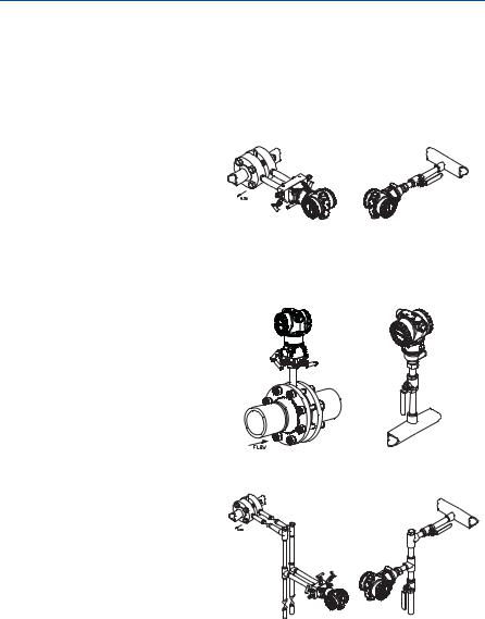
Transmitter installation
Step 1: Mount the transmitter
Liquid applications
1.Place taps to the side of the line.
2.Mount beside or below the taps.
3.Mount the transmitter so that the drain/vent valves are oriented upward.
Gas applications
1.Place taps in the top or side of the line.
2.Mount beside or above the taps.
Steam applications
1.Place taps to the side of the line.
2.Mount beside or below the taps.
3.Fill impulse lines with water.
Coplanar |
In-Line |
Coplanar |
In-Line |
Coplanar |
In-Line |
5

Quick Start Guide |
June 2014 |
|
|
Figure 2. Panel and Pipe Mounting
Panel mount(1) |
Pipe mount |
|
Coplanar flange |
|
Traditional flange |
|
Rosemount 3051T |
1. 5/16 x 1 1/2 Panel Bolts are customer supplied.
Bolting considerations
If the transmitter installation requires assembly of the process flanges, manifolds, or flange adapters, follow the assembly guidelines to ensure a tight seal for optimal performance characteristics of the transmitters. Use only bolts supplied with the transmitter or sold by Emerson® as spare parts. Figure 3 on page 7 illustrates common transmitter assemblies with the bolt length required for proper transmitter assembly.
6
June 2014 Quick Start Guide
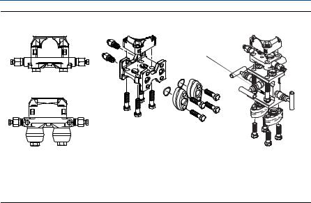
Figure 3. Common Transmitter Assemblies
A |
C |
D |
|
|
4 x 2.25-in. (57 mm) |
4 x 1.75-in. (44 mm) |
|
|
B |
|
|
|
4 x 1.75-in. (44 mm) |
4 x 1.50-in. (38 mm) |
4 x 2.88-in. (73 mm) |
|
4 x 1.75-in. (44 mm) |
A.Transmitter with Coplanar Flange
B.Transmitter with Coplanar Flange and Optional Flange Adapters
C.Transmitter with Traditional Flange and Optional Flange Adapters
D.Transmitter with Coplanar Flange and Optional Manifold and Flange Adapters
Bolts are typically carbon steel or stainless steel. Confirm the material by viewing the markings on the head of the bolt and referencing Table 2 on page 8. If bolt material is not shown in Table 2, contact a local Emerson Process Management representative for more information.
Carbon steel bolts do not require lubrication and the stainless steel bolts are coated with a lubricant to ease installation. However, no additional lubricant should be applied when installing either type of bolt.
Use the following bolt installation procedure:
1.Finger tighten the bolts.
2.Torque the bolts to the initial torque value using a crossing pattern. See Table 2 for initial torque value.
3.Torque the bolts to the final torque value using the same crossing pattern. See Table 2 for final torque value.
4.Verify the flange bolts are protruding through the sensor module bolt holes before applying pressure.
7
Quick Start Guide June 2014
Table 2. Torque Values for the Flange and Flange Adapter Bolts
Bolt material |
Head markings |
Initial torque |
Final torque |
Carbon Steel (CS) |
B7M |
300 in.-lbs. |
650 in.-lbs. |
|
|||
316 |
B8M |
|
|
|
|
316 |
|
Stainless Steel (SST) |
|
150 in.-lbs. |
300 in.-lbs. |
316 |
STM |
SW |
|
R |
316 |
316 |
|
|
|
|
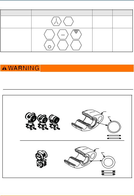
O-rings with flange adapters
Failure to install proper flange adapter O-rings may cause process leaks, which can result in death or serious injury. The two flange adapters are distinguished by unique O-ring grooves. Only use the O-ring that is designed for its specific flange adapter, as shown below.
Figure 4. O-ring Location
Rosemount 3051S / 3051 / 2051 / 3001 / 3095 |
A |
B |
C |
D |
Rosemount 1151 |
A |
B |
C |
D |
A.Flange Adapter
B.O-ring
C.PTFE Based
D.Elastomer
8
June 2014 |
Quick Start Guide |
Whenever the flanges or adapters are removed, visually inspect the o-rings. Replace them if there are any signs of damage, such as nicks or cuts. If you replace the o-rings, re-torque the flange bolts and alignment screws after installation to compensate for seating of the PTFE o-ring.
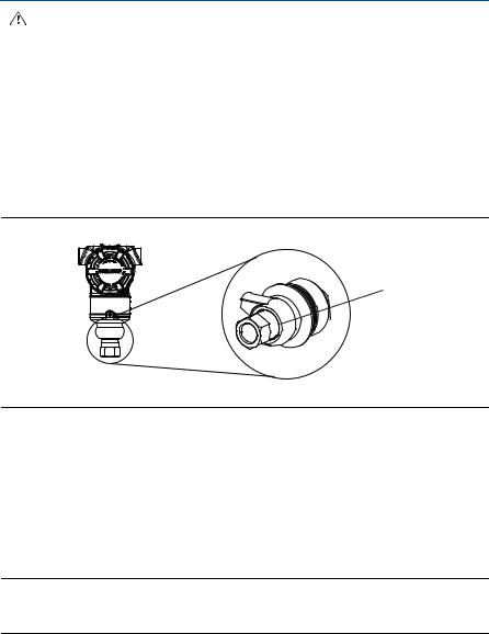
Inline gage transmitter orientation
The low side pressure port (atmospheric reference) on the inline gage transmitter is located in the neck of the transmitter, behind the housing. The vent path is 360° around the transmitter between the housing and sensor. (See Figure 5.)
Keep the vent path free of any obstruction, including but not limited to paint, dust, and lubrication by mounting the transmitter so that fluids can drain away.
Figure 5. Inline Gage Low Side Pressure Port
A
A. Pressure Port Location
Step 2: Tagging
Commissioning (paper) tag
To identify which device is at a particular location use the removable tag provided with the transmitter. Ensure the physical device tag (PD Tag field) is properly entered in both places on the removable commissioning tag and tear off the bottom portion for each transmitter.
Note
The device description loaded in the host system must be at the same revision as this device, see “System readiness” on page 3.
9
Quick Start Guide |
June 2014 |
|
|
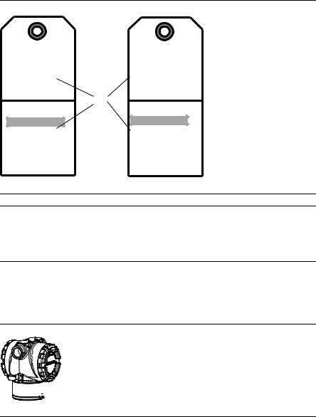
Figure 6. Commissioning Tag
Commissioning Tag |
Commissioning Tag |
DEVICE ID: |
DEVICE ID: |
0011513051010001440-121698091725 |
001151AC00010001440-121698091725 |
|
|
DEVICE REVISION: 7.2 |
DEVICE REVISION: 8.1 |
PHYSICAL DEVICE TAG |
PHYSICAL DEVICE TAG |
|
A |
DEVICE ID: |
DEVICE ID: |
0011513051010001440-121698091725 |
001151AC00010001440-121698091725 |
Device Barcode
DEVICE REVISION: 7.2
S / N :
PHYSICAL DEVICE TAG
Device Barcode
DEVICE REVISION: 8.1
S / N :
PHYSICAL DEVICE TAG
A. Device revision
Note
The device description loaded in the host system must be at the same revision as this device. The device description can be downloaded from the host system website or www.rosemount.com by selecting Download Device Drivers under Product Quick Links. You can also visit www.fieldbus.org and select End User Resources.
Step 3: Housing rotation
To improve field access to wiring or to better view the optional LCD display:
Figure 7. Housing Rotation

 A
A
A.Housing Rotation Set Screw (5/64-inch)
1.Loosen the housing rotation set screw using a 5/64 -in. hex wrench.
2.Rotate the housing clockwise to the desired location.
3.If the desired location cannot be achieved due to thread limit, rotate the housing counterclockwise to the desired location (up to 360° from thread limit).
4.Retighten the housing rotation set screw to no more than 7 in-lbs when desired location is reached.
10
June 2014 |
Quick Start Guide |
Step 4: Set the switches
Set Simulate and Security switch configuration before installation as shown in
Figure 8.
The simulate switch enables or disables simulated alerts and simulated AI Block status and values. The default simulate switch position is enabled.
The Security switch allows (unlocked symbol) or prevents (locked symbol) any configuration of the transmitter.
-Default security is off (unlocked symbol).
-The security switch can be enabled or disabled in software.
Use the following procedure to change the switch configuration:
1.If the transmitter is installed, secure the loop, and remove power.
2.Remove the housing cover opposite the field terminal side. Do not remove the instrument cover in explosive atmospheres when the circuit is live.
3.Slide the security and simulate switches into the preferred position.
4.Replace the housing cover.
Note
It is recommended the cover be tightened until there is no gap between the cover and the housing.
Figure 8. Simulate and Security Switches
C
B
A


 D
D
E
F
A.Simulate Disabled Position
B.Simulate Switch
C.Simulate Enabled Position (default)
D.Security Locked Position
E.Security Switch
F.Security Unlocked Position (default)
11
Loading...