


Instruction Manual
D103748X012
September 2020
T205 Series
T205 Series Tank Blanketing Regulators
Table of Contents |
|
Introduction.................................................................. |
1 |
Specifications............................................................... |
2 |
Principle of Operation................................................... |
4 |
Installation.................................................................... |
4 |
Overpressure Protection.............................................. |
6 |
Startup, Adjustment and Shutdown.............................. |
6 |
Maintenance................................................................. |
7 |
Parts Ordering............................................................ |
10 |
Parts List.................................................................... |
10 |
▲ WARNING
Failure to follow these instructions or to properly install and maintain this equipment could result in an explosion, fire and/or chemical contamination causing property damage and personal injury or death.
Fisher™ regulators must be installed, operated and maintained in accordance with federal, state and local codes, rules and regulations and Emerson Process Management Regulator Technologies Inc. (Emerson) instructions.
If the regulator discharges process fluid or a leak develops in the system, service to the unit may be required.
Failure to correct trouble could result in a hazardous condition.
Call a qualified service person to service the unit. Installation, operation and maintenance procedures performed by unqualified person may result
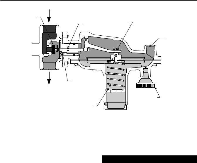
Figure 1. Type T205 Tank Blanketing Regulator
in improper adjustment and unsafe operation. Either condition may result in equipment damage or personal injury.
Only a qualified person must install or service the T205 Series regulator.
Introduction
Scope of the Manual
This Instruction Manual provides instruction for installation, startup, maintenance and parts ordering information for the T205 Series tank blanketing regulators.
Product Description
T205 Series tank blanketing regulator is a directoperated and spring-loaded regulator. The regulator prevents a stored liquid from vaporizing into the atmosphere, reduces liquid combustibility and prevents oxidation or contamination of the product by reducing its exposure to air. T205 Series maintains a slightly positive pressure and thereby reduces the possibility of tank wall collapse during pump out operation.

T205 Series
Specifications
The Specifications section on this page provides the ratings and other specifications for the T205 Series. Factory specification such as type, maximum inlet pressure, maximum temperature, maximum outlet pressure, spring range and orifice size are stamped on the nameplate fastened on the regulator at the factory.
Product Configurations
Type T205: Tank blanketing regulator with outlet pressure range of 1 in. w.c. to 7 psig / 2.5 mbar to 0.48 bar in seven different spring ranges and has internal pressure registration requiring no downstream control line.
Type T205M: Similar to Type T205 but has a blocked throat and a downstream control line connection for external pressure registration.
Type T205H: Similar to Type T205, except outlet (casing) pressure rating equals the inlet rating (both 150 psig / 10.3 bar) and low temperature to -20°F / -29°C.
Type T205HM: Similar to Type T205M, except outlet (casing) pressure rating equals the inlet rating (both 150 psig / 10.3 bar) and low temperature to -20°F / -29°C
Body Sizes and End Connection Styles
See Table 1
Maximum Allowable Inlet Pressure(1)
See Table 1
Maximum Operating Inlet Pressure(1)
See Table 2
Maximum Outlet (Casing) Pressure(1)
Types T205 and T205M
Gray cast iron: 35 psig / 2.4 bar
WCC Carbon steel, LCC Carbon steel or CF8M/CF3M Stainless steel: 75 psig / 5.2 bar
Types T205H and T205HM
WCC Carbon steel or CF8M/CF3M Stainless steel:
150 psig / 10.3 bar
Outlet (Control) Pressure Ranges(1)
See Table 3
Shutoff Classification per ANSI/FCI 70-3-2004
Class VI (Soft Seat)
Pressure Registration
Types T205 and T205H: Internal Types T205M and T205HM: External
Material Temperature Capabilities(1)(2)(4)
Elastomer Parts
Nitrile (NBR):
Types T205 and T205M: -40 to 180°F / -40 to 82°C Types T205H and T205HM: -20 to 180°F /
-29 to 82°C
Fluorinated Ethylene Propylene (FEP)(3):
-20 to 180°F / -29 to 82°C
Fluorocarbon (FKM)(3): 40 to 300°F / 4 to 149°C Ethylene Propylene Diene (EPDM)(3):
-20 to 225°F / -29 to 107°C
Perfluoroelastomer (FFKM)(3):
0 to 300°F / -18 to 149°C
Body Materials
Gray cast iron(3): -20 to 300°F / -29 to 149°C WCC Carbon steel: -20 to 300°F / -29 to 149°C LCC Carbon steel: -40 to 300°F / -40 to 149°C
CF8M/CF3M Stainless steel:
-40 to 300°F / -40 to 149°C
Spring Case Vent Connection
1/4 NPT
Diaphragm Case Control Line Connection (Types T205M and T205HM)
1/2 NPT
Approximate Weight
17.7 lbs / 8 kg
1.The pressure/temperature limits in this Instruction Manual and any applicable standard or code limitation should not be exceeded.
2.See Table 5 for operating temperature ranges for available trim combinations.
3.Not available for Types T205H and T205HM.
4.Special low temperature constructions for process temperatures between -76 to 180°F / -60 to 82°C are available by request. The low temperature construction passed Emerson laboratory testing for lockup and external leakage down to -76°F / -60°C.
Table 1. Body Sizes, End Connection Styles and Maximum Allowable Inlet Pressures
|
|
BODY SIZE |
|
BODY MATERIAL |
END CONNECTION STYLES(1) |
MAXIMUM ALLOWABLE INLET PRESSURE |
||
|
In. |
|
DN |
|
psig |
bar |
||
|
|
|
|
|
||||
|
|
|
|
|
Gray cast iron(2) |
NPT |
150 |
10.3 |
|
3/4 or 1 |
|
20 or 25 |
|
WCC Carbon steel |
NPT, CL150 RF, |
|
|
|
|
|
LCC Carbon steel |
200(3) |
13.8(3) |
|||
|
|
|
|
|
||||
|
|
|
|
|
|
CL300 RF or PN 16/25/40 RF |
|
|
|
|
|
|
|
CF8M/CF3M Stainless steel(4) |
|
|
|
|
|
|
|
|
|
|
|
|
1. All flanges are welded. Weld-on flange dimension is 14 in. / 356 mm face-to-face. |
|
|
|
|||||
2. |
Not available for Types T205H and T205HM. |
|
|
|
|
|||
3. |
Inlet pressure is limited to 150 psig / 10.3 bar for Types T205H and T205HM. |
|
|
|
||||
4. |
Pipe nipples and flanges are 316 Stainless steel for flanged body assemblies. |
|
|
|
||||
|
|
|
|
|
|
|
|
|
2

T205 Series
VALVE DISK
STEM
LEVER PUSHER POST
PIPE PLUG
DIAPHRAGM |
PITOT TUBE
CONTROLSPRING
ERSA02735 |
TYPEY602-1VENT |
|
INLET PRESSURE
OUTLET PRESSURE
ATMOSPHERICPRESSURE
Figure 2. Types T205 and T205H with Internal Registration Operational Schematics
Table 2. T205 Series Maximum Operating Inlet Pressure
|
|
|
|
|
|
|
MAXIMUM OPERATING INLET PRESSURE(1) |
|
|
|
|
|
|||||
ORIFICE SIZE |
1 to 2.5 In. w.c. / |
2.5 to 7 In. w.c. / |
7 to 16 In. w.c. / |
0.5 to 1.2 psig / |
1.2 to 2.5 psig / |
2.5 to 4.5 psig / |
4.5 to 7 psig / |
||||||||||
2.5 to 6.2 mbar |
6.2 to 17 mbar |
17 to 40 mbar |
34 to 83 mbar |
83 to 172 mbar |
0.17 to 0.31 bar |
0.31 to 0.48 bar |
|||||||||||
|
|
Outlet (Control) |
Outlet (Control) |
Outlet (Control) |
Outlet (Control) |
Outlet (Control) |
Outlet (Control) |
Outlet (Control) |
|||||||||
|
|
Pressure Setting |
Pressure Setting |
Pressure Setting |
Pressure Setting |
Pressure Setting |
Pressure Setting |
Pressure Setting |
|||||||||
In. |
mm |
psig |
bar |
psig |
bar |
psig |
bar |
psig |
|
bar |
psig |
|
bar |
psig |
bar |
psig |
bar |
|
|
|
|
|
|
|
3/4 In. / DN |
20 Body Size |
|
|
|
|
|
|
|
|
|
1/8 |
3.2 |
200(2) |
13.8(2) |
200(2) |
13.8(2) |
200(2) |
13.8(2) |
200(2) |
|
13.8(2) |
200(2) |
|
13.8(2) |
200(2) |
13.8(2) |
200(2) |
13.8(2) |
1/4 |
6.4 |
125 |
8.62 |
175(2) |
12.1(2) |
200(2) |
13.8(2) |
200(2) |
|
13.8(2) |
200(2) |
|
13.8(2) |
200(2) |
13.8(2) |
200(2) |
13.8(2) |
3/8 |
9.5 |
60 |
4.14 |
80 |
5.52 |
200(2) |
13.8(2) |
200(2) |
|
13.8(2) |
200(2) |
|
13.8(2) |
200(2) |
13.8(2) |
200(2) |
13.8(2) |
1/2 |
13 |
30 |
2.07 |
40 |
2.76 |
125 |
8.62 |
150 |
|
10.3 |
200(2) |
|
13.8(2) |
200(2) |
13.8(2) |
200(2) |
13.8(2) |
9/16 |
14 |
20 |
1.38 |
30 |
2.07 |
100 |
6.89 |
125 |
|
8.62 |
200(2) |
|
13.8(2) |
200(2) |
13.8(2) |
200(2) |
13.8(2) |
|
|
|
|
|
|
|
1 In. / DN |
25 Body Size |
|
|
|
|
|
|
|
|
|
1/8 |
3.2 |
200(2) |
13.8(2) |
200(2) |
13.8(2) |
200(2) |
13.8(2) |
200(2) |
|
13.8(2) |
200(2) |
|
13.8(2) |
200(2) |
13.8(2) |
200(2) |
13.8(2) |
1/4 |
6.4 |
100 |
6.89 |
150 |
10.3 |
150 |
10.3 |
150 |
|
10.3 |
200(2) |
|
13.8(2) |
200(2) |
13.8(2) |
200(2) |
13.8(2) |
3/8 |
9.5 |
40 |
2.76 |
80 |
5.52 |
150 |
10.3 |
150 |
|
10.3 |
200(2) |
|
13.8(2) |
200(2) |
13.8(2) |
200(2) |
13.8(2) |
1/2 |
13 |
30 |
2.07 |
40 |
2.76 |
125 |
8.62 |
150 |
|
10.3 |
200(2) |
|
13.8(2) |
200(2) |
13.8(2) |
200(2) |
13.8(2) |
9/16 |
14 |
20 |
1.38 |
15 |
1.03 |
100 |
6.89 |
125 |
|
8.62 |
200(2) |
|
13.8(2) |
200(2) |
13.8(2) |
200(2) |
13.8(2) |
1. At maximum inlet pressure, minimum achievable setpoints may vary based on process conditions.
2. Inlet pressure is limited to 150 psig / 10.3 bar for gray cast iron bodies and for Types T205H and T205HM.
Table 3. Outlet (Control) Pressure Ranges and Spring Information
OUTLET (CONTROL) PRESSURE RANGE |
SPRING PART NUMBER |
SPRING COLOR |
SPRING WIRE DIAMETER |
SPRING FREE LENGTH |
||||
In. w.c. |
mbar |
In. |
mm |
In. |
mm |
|||
|
|
|||||||
1 to 2.5(1)(2) |
2.5 to 6.2(1)(2) |
1B558527052 |
Orange |
0.072 |
1.8 |
3.25 |
82.6 |
|
2.5 to 7(1) |
6.2 to 17(1) |
1B653827052 |
Red |
0.085 |
2.2 |
3.63 |
92.2 |
|
7 to 16 |
17 to 40 |
1B653927022 |
Unpainted |
0.105 |
2.7 |
3.75 |
95.2 |
|
0.5 to 1.2 psig |
34 to 83 |
1B537027052 |
Yellow |
0.114 |
2.9 |
4.31 |
109 |
|
1.2 to 2.5 psig |
83 to 172 |
1B537127022 |
Green |
0.156 |
4.0 |
4.06 |
103 |
|
2.5 to 4.5 psig |
0.17 to 0.31 bar |
1B537227022 |
Light Blue |
0.187 |
4.8 |
3.94 |
100 |
|
4.5 to 7 psig |
0.31 to 0.48 bar |
1B537327052 |
Black |
0.218 |
5.5 |
3.98 |
101 |
|
1. To achieve the published outlet pressure range the spring case must be installed pointing down.
2. Do not use Fluorocarbon (FKM) diaphragm with this spring at diaphragm temperatures lower than 60°F / 16°C.
3
T205 Series
VALVE DISK
O-RINGSTEMSEAL PUSHER POST
CONTROL LINE |
CONNECTION |
THROAT SEAL
TYPEY602-1VENT
ERSA02736 |
|
|
|
|
INLET PRESSURE |
CONTROLSPRING |
|
|
|
||
|
|
||
|
OUTLET PRESSURE |
|
|
|
|
|
|
|
ATMOSPHERICPRESSURE |
|
|
|
|
|
|
Figure 3. Types T205M and T205HM with External Registration Operational Schematics
T205 Series is available in four configurations:
Types T205 and T205H for internal pressure registration requiring no downstream control line and Types T205M and T205HM which have a blocked throat and a downstream control line connection for external pressure registration.
Principle of Operation
T205 Series tank blanketing regulator controls the vapor space pressure over a stored liquid. When liquid is pumped out of the tank or vapors in the tank condense, the pressure in the tank decreases. Tank pressure is sensed by the actuator diaphragm. Spring force pushes the pusher post assembly upward, the valve disk moves away from the orifice, allowing the gas flow to increase to maintain tank pressure. See
Figures 2 and 3.
When pressure in the tank increases, the actuator diaphragm is pushed downward. Through the action of the pusher post assembly, lever and valve stem, the valve disk moves closer to the orifice reducing gas flow.
Installation
▲ WARNING
Personal injury, property damage, equipment damage or leakage due to escaping gas or bursting of pressurecontaining parts may result if this regulator is overpressured or installed where service conditions could exceed the limits given in the Specifications section or where conditions exceed any ratings of the adjacent piping or piping connections.
Refer to Overpressure Protection section for recommendations on how to prevent service conditions from exceeding those limits.
To avoid such injury or damage, provide pressure-relieving or pressure-limiting devices (as required by the appropriate code, regulation or standard) to prevent service conditions from exceeding limits.
4
T205 Series
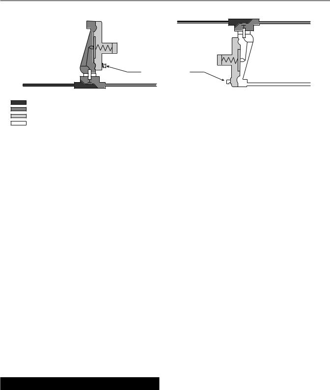
HORIZONTAL PIPELINE
|
VENT POINTED DOWN |
HORIZONTAL PIPELINE |
DOWNSTREAM CONTROL LINE |
TYPES T205 AND T205H |
TYPES T205M AND T205HM |
B2626
INLET PRESSURE
OUTLET PRESSURE
ATMOSPHERIC PRESSURE
LOADING PRESSURE
Figure 4. T205 Series Actuator Casing Drainage Schematics
Additionally, physical damage to the regulator could cause personal injury or property damage due to escaping gas. To avoid such injury or damage, install the regulator in a safe location.
Note
If the regulator is shipped mounted on another unit, install that unit according to the appropriate Instruction Manual.
1.Only personnel qualified through training and experience shall install, operate and maintain a regulator. For a regulator that is shipped separately, make sure there is no damage to or debris in the regulator. Also ensure that all tubing and piping are clean and unobstructed.
2.The regulator may be installed in any position as long as the flow through the body is in the direction indicated by the arrow on the body. When using
a T205 Series regulator, for proper operation to achieve the published capacities at low setpoint, the spring case barrel should be installed pointed down as shown in Figure 1. For complete actuator drainage, the regulator should be installed as shown in Figure 4. If continuous operation of the system is required during inspection or maintenance, install a three-valve bypass around the regulator.
▲ WARNING
Aregulator may vent some gas to the atmosphere. In hazardous or flammable gas service, vented gas may accumulate and cause personal injury, death or property damage due to fire or explosion.
Vent a regulator in hazardous gas service to a remote, safe location away from air intakes or any hazardous area. The vent line or stack opening must be protected against condensation or clogging.
3.To keep the spring case vent (key 26, Figures 7 to 10) from being plugged or the spring case from collecting moisture, corrosive chemicals or other foreign material, point the vent down or otherwise protect it. The diaphragm casing (key 4, Figures 7 to 10) may be rotated in order to obtain desired positioning.
4.To remotely vent the regulator, remove the vent (key 26, Figures 7 to 10) and install obstructionfree tubing or piping into the 1/4 NPT vent tapping. Provide protection on a remote vent by installing a screened vent cap into the remote end of the vent pipe.
5.Types T205M and T205HM require a downstream control line. Be sure to install the control line before putting the regulator into operation. Make the control line as short and straight as possible and do not install it in a location where flow may be turbulent.
Restrictions in the control line can prevent proper pressure registration. When using a hand valve, it should be a full flow valve, such as a full port ball valve. Install the control line sloping downward toward the tank to prevent condensation buildup and avoid low points (or traps) that could catch liquid. The sensing line must enter the tank above the liquid level at a point that senses the vapor space pressure and is free from turbulence associated with tank nozzles or vents. The control line pipe should be at least
1/2 in. / 13 mm in diameter and increase 1 pipe size for every 10 ft. / 3.05 m of control line, with setpoint less than 5 in. w.c. / 12 mbar.
5
 Loading...